vfd customer display - fec...
TRANSCRIPT

VFD CUSTOMER DISPLAY
USER’ S MANUAL

CONTENTS 1 VFD
Contents .................................................................................
1 Features ................................................................................. 2
Specifications - 9mm .............................................................. 3
Block Diagram ....................................................................... 6
Interface Connections ............................................................. 7
Usage Notes ........................................................................... 9
Switch Settings ....................................................................... 11
Firich Command Set Table ..................................................... 12
Firich Display Modes Description .......................................... 14
Firich Command Set Description ............................................ 16
Aedex Command Set Table ..................................................... 27
DSP800 Command Set Table .................................................. 28
Epson Command Set Table ..................................................... 29
Font Tables ............................................................................ 32
Rev. Date20100803

FEATURES
VFD 2
• High brightness vacuum fluorescent display for excellent visibility over a wide viewing angle.
• Available in 9.0mm or high characters.
• 40 characters in 20 columns by 2 lines format.
• Thirteen sets of international characters, plus one set of user defined characters allows total flexibility in display fonts.
• Standard RS-232C serial interface for data communication, with 9600 and 19200 baud rate selection.
• A pass-through output is provided for cascading display or printer without additional serial port.
• Easy programming using Escape sequence commands.
• Emulation of Aedex, Epson and DSP800 command sets.
• Display can swivel and tilt to a wide range of angles.
• Adjustable display height.
• Uses 9-24V DC unregulated supply.
• Power may be sourced from system, with the bracket and cable kit supplied in typical configuration.
• Optional AC adaptors in various configurations for all AC voltages.
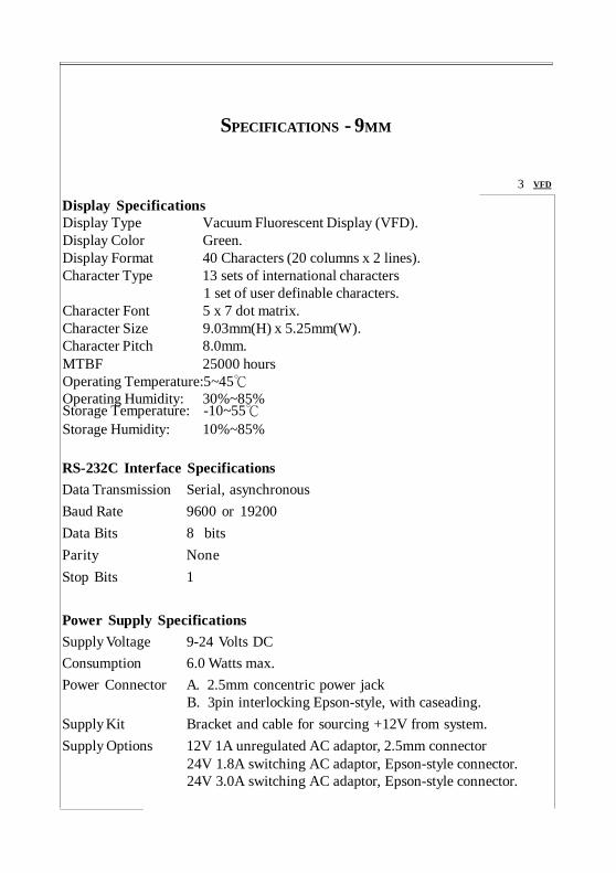
SPECIFICATIONS - 9MM
Display Specifications Display Type Vacuum Fluorescent Display (VFD). Display Color Green. Display Format 40 Characters (20 columns x 2 lines). Character Type 13 sets of international characters
1 set of user definable characters. Character Font 5 x 7 dot matrix. Character Size 9.03mm(H) x 5.25mm(W). Character Pitch 8.0mm. MTBF 25000 hours Operating Temperature:5~45℃ Operating Humidity: 30%~85% Storage Temperature: -10~55℃
Storage Humidity: 10%~85%
RS-232C Interface Specifications Data Transmission Serial, asynchronous Baud Rate 9600 or 19200 Data Bits 8 bits Parity None Stop Bits 1
3 VFD
Power Supply Specifications Supply Voltage 9-24 Volts DC Consumption 6.0 Watts max. Power Connector A. 2.5mm concentric power jack
B. 3pin interlocking Epson-style, with caseading. Supply Kit Bracket and cable for sourcing +12V from system. Supply Options 12V 1A unregulated AC adaptor, 2.5mm connector
24V 1.8A switching AC adaptor, Epson-style connector. 24V 3.0A switching AC adaptor, Epson-style connector.
VFD 4
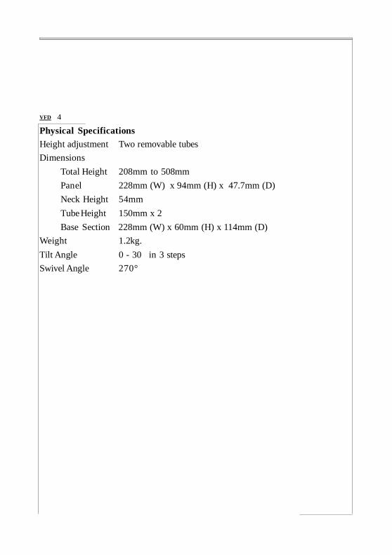
Physical Specifications Height adjustment Two removable tubes Dimensions
Total Height 208mm to 508mm Panel 228mm (W) x 94mm (H) x 47.7mm (D) Neck Height 54mm Tube Height 150mm x 2 Base Section 228mm (W) x 60mm (H) x 114mm (D)
Weight 1.2kg. Tilt Angle 0 - 30 in 3 steps Swivel Angle 270°
508
94.0
150
358
208
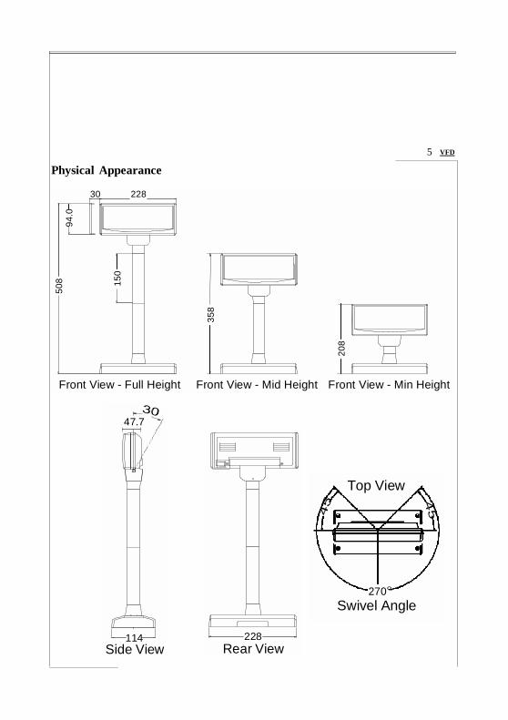
Physical Appearance
5 VFD
30 228
Front View - Full Height Front View - Mid Height Front View - Min Height
47.7
Top View
270° Swivel Angle
114
Side View 228
Rear View

BLOCK DIAGRAM
6 VFD
Head Unit
VFD Module
Filament Drive VFD Drive
V-Filament Generator
+5V Regulator
VFD
Driver Controller
Power Switch
RS-232C Interface
Mode Select
+12V
RJ-45
Base to Head Interconnect
+12V
RJ-45
JP1 DC In
DB9F RS-232C From
System
Base Unit
DB9M RS-232C To Next Device
VFD Customer Display Block Diagram

INTERFACE CONNECTIONS
VFD 7
Interface Pin Assignment - 2.5mm DC Jack To Next Device
To Host (DB9F) 1 DCD 2 RxD
3 TxD 4 DTR 5 Gnd
6 DSR
7 RTS 8 CTS 9 +V
DC In Jack Center +V Outer Gnd
To LCD (RJ45) 2 Device TxD 3 Host TxD 6 Gnd 7 Gnd 4 Host DSR 5 Device DSR 8 +V 9 +V
(DB9M) 1 DCD 2 RxD 3 TxD 4 DTR 5 Gnd 6 DSR 7 RTS 8 CTS 9 +V
Base Interface Plate - 2.5mm DC Jack
1 1
+V Gnd
DC Power To Host To Next Device To Display
8 VFD
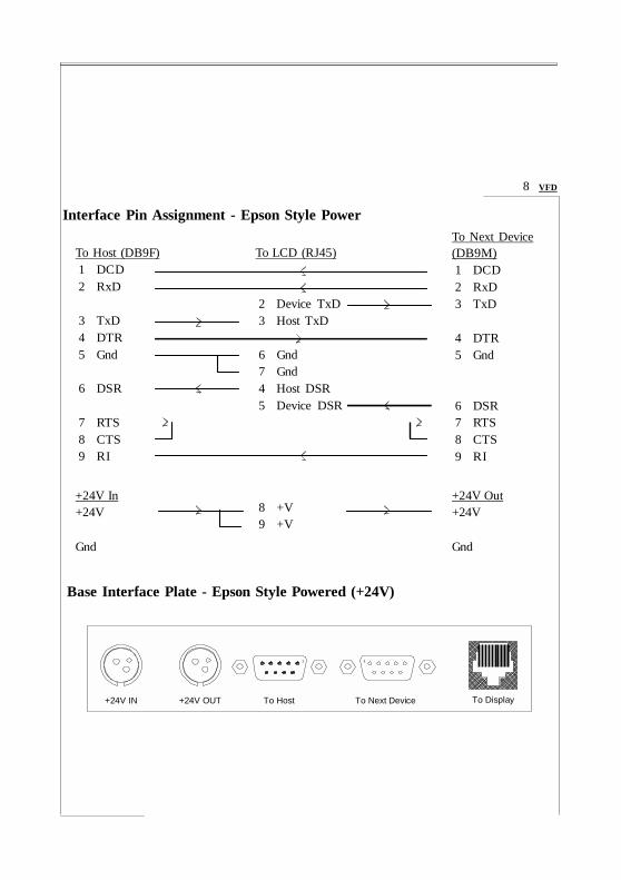
Interface Pin Assignment - Epson Style Power To Next Device
To Host (DB9F) 1 DCD 2 RxD
3 TxD 4 DTR 5 Gnd
6 DSR
7 RTS 8 CTS 9 RI
+24V In +24V
Gnd
To LCD (RJ45) 2 Device TxD 3 Host TxD 6 Gnd 7 Gnd 4 Host DSR 5 Device DSR 8 +V 9 +V
(DB9M) 1 DCD 2 RxD 3 TxD 4 DTR 5 Gnd 6 DSR 7 RTS 8 CTS 9 RI
+24V Out +24V Gnd
Base Interface Plate - Epson Style Powered (+24V)
1 1
+24V IN +24V OUT To Host To Next Device To Display

USAGE NOTES
VFD 9
Signal Naming Please note that the signal naming of the pin assignment for the DB9 RS-232 connectors on the Custmer Display follows the convention for DCE. The host is viewed as DTE. Thus, TxD would be an output for the host, the same name applies to an input of the DCE, such as the Customer Display, which would be wired to the host pin by the same name.
Handshaking and Pass-through The handshake signals are another source of confusion. There are essentially two sets of control lines, DTR/DSR and RTS/CTS. Disregarding the original designation for teletype purpose, they serve essentially identical function. DTR and RTS are from host to device, logical high on both signals the host is ready, either one low indicates a not-ready status. DSR and CTS are from device to host, logical high on both signals the device is ready. Printer some times use DCD as the ready signal to the host.
The Customer Display uses only TxD for receiving data from host, and DTR/ DSR for handshaking. All the other signals are routed to the following device in such a way as to ensure proper pass-through function. The use of a printer with Customer Display should always have the printer connected to the next device connector of the Customer Display and the Customer Display connected to the host. Paralleling the signal lines, as some times done to connect multiple devices to a RS-232 port, may lead to improper operation.
Power Supply and Pin 9 Pin 9 of DB9, originally designated as RI (ring indicator) input to host, is used as the power supply pin. Many systems has provision for supplying a +12V source on this pin to peripheral devices. The supply is then routed to the same pin on connector to the next device, a second Customer Display, for example. Printers usually has a separate power source, leaving pin 9 open. Precaution is necessary not to connect any device with the RI line active, such as a modem, to the Customer Display, failure to observe may lead to

10 VFD
permanent damage. To find out if it is safe to connect a device, use a voltmeter to measure the RI pin of the device while it is powered on. If the reading is within +/- 3V, it is likely to be safe.
Power Bracket Kit This kit is supplied in the typical configuration for Customer Display with 2.5mm DC jack. Using this feature eliminates the need for a AC adapter when power cannot be obtained from pin9 of RS-232 as described in previous note. A bracket with an RCA jack is included that fits the rear standard PC expansion slot location, with a connector to source +5V from system`s peripheral power connector. A cable with a RCA plug on one end and a DC plug on the other end routes power to the Customer Display.
Epson-Style Version This version is functionally identical to the standard version, except for power connectors which are compatible with Epson POS printers. Two power jacks are provided for cascading a single power source for use by both the Customer Display and printer. Two adaptors are available, 1.8A and 3.0A at 24V, the choice would depend on the combined consumption of the printer plus the Customer Display.
Power-on Moving Message At Firich Command Set mode, upon power-on a moving message is displayed after self-check. This message is stored in EEPROM and may be changed by following the steps below.
1. Send 0Ch to Customer Display to clear display.
2. Send desired message to Customer Display.
3. Send 1Bh 53h 31h to store the message in EEPROM.

SWITCH SETTINGS
VFD 11
Baud Rate Select
Sw8 Baud RateOn 9600 Off 19200
Firich COMMAND SET TABLE
12 VFD
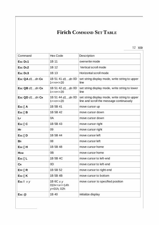
Command Hex Code Description ESC DC1 1B 11 overwrite mode ESC DC2 1B 12 Vertical scroll mode ESC DC3 1B 13 Horizontal scroll mode ESC QA d1...dn CR 1B 51 41 d1...dn 0D
1<=n<=20 set string display mode, write string to upper line
ESC QB d1...dn CR 1B 51 42 d1...dn 0D1<=n<=20
set string display mode, write string to lower line
ESC QD d1...dn CR 1B 51 44 d1...dn 0D1<=n<=20
set string display mode, write string to upper line and scroll the message continuously
ESC [ A 1B 5B 41 move cursor up ESC [ B 1B 5B 42 move cursor down LF 0A move cursor down ESC [ C 1B 5B 43 move cursor right HT 09 move cursor right ESC [ D 1B 5B 44 move cursor left BS 08 move cursor left ESC [ H 1B 5B 48 move cursor home HOM 0B move cursor home ESC [ L 1B 5B 4C move cursor to left-end CR 0D move cursor to left-end ESC [ R 1B 5B 52 move cursor to right-end ESC [ K 1B 5B 4B move cursor to bottom ESC l x y 1B 6C x y
01h<=x<=14h y=01h, 02h
move cursor to specified position
ESC @ 1B 40 initialize display
VFD 13
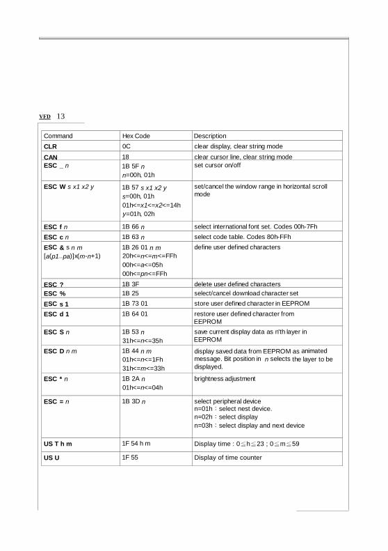
Command Hex Code Description CLR 0C clear display, clear string mode CAN 18 clear cursor line, clear string mode ESC _ n 1B 5F n
n=00h, 01h set cursor on/off
ESC W s x1 x2 y 1B 57 s x1 x2 y s=00h, 01h 01h<=x1<=x2<=14h y=01h, 02h
set/cancel the window range in horizontal scroll mode
ESC f n 1B 66 n select international font set. Codes 00h-7Fh ESC c n 1B 63 n select code table. Codes 80h-FFh ESC & s n m [a(p1..pa)]x(m-n+1)
1B 26 01 n m 20h<=n<=m<=FFh 00h<=a<=05h 00h<=pn<=FFh
define user defined characters
ESC ? 1B 3F delete user defined characters ESC % 1B 25 select/cancel download character set ESC s 1 1B 73 01 store user defined character in EEPROM ESC d 1 1B 64 01 restore user defined character from
EEPROM ESC S n 1B 53 n
31h<=n<=35h save current display data as n'th layer in EEPROM
ESC D n m 1B 44 n m 01h<=n<=1Fh 31h<=m<=33h
display saved data from EEPROM as animated message. Bit position in n selects the layer to be displayed.
ESC * n 1B 2A n 01h<=n<=04h
brightness adjustment
ESC = n 1B 3D n select peripheral device n=01h:select nest device. n=02h:select display n=03h:select display and next device
US T h m 1F 54 h m Display time : 0≦h≦23 ; 0≦m≦59 US U 1F 55 Display of time counter
Firich DISPLAY MODES DESCRIPTION
14 VFD
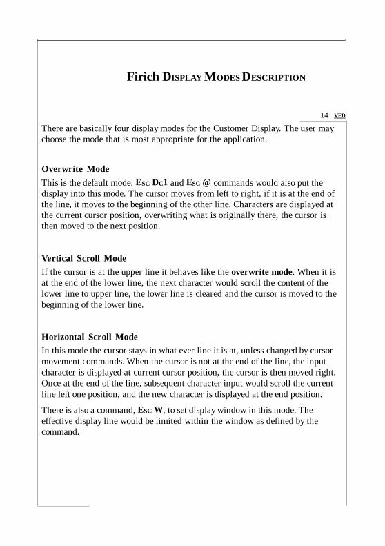
There are basically four display modes for the Customer Display. The user may choose the mode that is most appropriate for the application.
Overwrite Mode This is the default mode. ESC DC1 and ESC @ commands would also put the display into this mode. The cursor moves from left to right, if it is at the end of the line, it moves to the beginning of the other line. Characters are displayed at the current cursor position, overwriting what is originally there, the cursor is then moved to the next position.
Vertical Scroll Mode If the cursor is at the upper line it behaves like the overwrite mode. When it is at the end of the lower line, the next character would scroll the content of the lower line to upper line, the lower line is cleared and the cursor is moved to the beginning of the lower line.
Horizontal Scroll Mode In this mode the cursor stays in what ever line it is at, unless changed by cursor movement commands. When the cursor is not at the end of the line, the input character is displayed at current cursor position, the cursor is then moved right. Once at the end of the line, subsequent character input would scroll the current line left one position, and the new character is displayed at the end position.
There is also a command, ESC W, to set display window in this mode. The effective display line would be limited within the window as defined by the command.
VFD 15
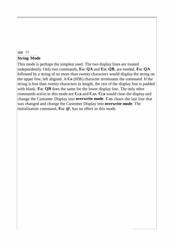
String Mode This mode is perhaps the simplest used. The two display lines are treated independently. Only two commands, ESC QA and ESC QB, are needed. ESC QA followed by a string of no more than twenty characters would display the string on the upper line, left aligned. A CR (0Dh) character terminates the command. If the string is less than twenty characters in length, the rest of the display line is padded with blank. ESC QB does the same for the lower display line. The only other commands active in this mode are CLR and CAN. CLR would clear the display and change the Customer Display into overwrite mode. CAN clears the last line that was changed and change the Customer Display into overwrite mode. The initialisation command, ESC @, has no effect in this mode.

Firich COMMAND SET DESCRIPTION
ESC DC1 /Set overwrite mode/ Dec. Format [027] [017] Hex. Format: [1Bh] [11h]
16 VFD
Description: Set the display to overwrite mode. This is the default power on display mode.
ESC DC2 /Set vertical scroll mode/ Dec. Format [027] [018] Hex. Format: [1Bh] [12h] Description: Set the display to vertical scroll mode.
ESC DC3 /Set horizontal scroll mode/ Dec. Format [027] [019] Hex. Format: [1Bh] [13h] Description: Set the display to horizontal scroll mode.
ESC QA d1d2d3 . . . dn CR /Set string display mode, write string to upper line/ Dec.Format [027] [081] [065] d1d2d3 . . . dn [013] Hex. Format: [1Bh] [51h] [41h] d1d2d3 . . . dn [0Dh]
{20h <= dn <= FFh, 1 <= n <=20} Description: Set string display mode, write to the upper line.
The string display mode can be cancelled with CLR or CAN.
ESC QB d1d2d3 . . . dn CR /Set string display mode, write string to lower line/ Dec.Format [027] [081] [066] d1d2d3 . . . dn [013] Hex. Format: [1Bh] [51h] [42h] d1d2d3 . . . dn [0Dh]
{20h <= dn <= FFh, 1 <= n <=20} Description: Set string display mode, write to the lower line.
The string display mode can be cancelled with CLR or CAN.
VFD 17
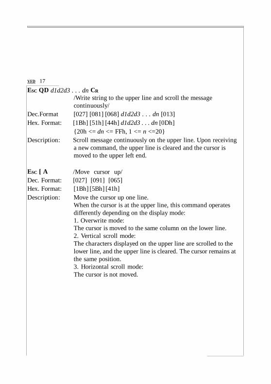
ESC QD d1d2d3 . . . dn CR /Write string to the upper line and scroll the message continuously/
Dec.Format [027] [081] [068] d1d2d3 . . . dn [013] Hex. Format: [1Bh] [51h] [44h] d1d2d3 . . . dn [0Dh]
{20h <= dn <= FFh, 1 <= n <=20} Description: Scroll message continuously on the upper line. Upon receiving
a new command, the upper line is cleared and the cursor is moved to the upper left end.
ESC [ A /Move cursor up/ Dec. Format: [027] [091] [065] Hex. Format: [1Bh] [5Bh] [41h] Description: Move the cursor up one line.
When the cursor is at the upper line, this command operates differently depending on the display mode: 1. Overwrite mode: The cursor is moved to the same column on the lower line. 2. Vertical scroll mode: The characters displayed on the upper line are scrolled to the lower line, and the upper line is cleared. The cursor remains at the same position. 3. Horizontal scroll mode: The cursor is not moved.

ESC [ B /Move cursor down/
LF
Dec. Format: [027] [091] [066] [010]
Hex. Format: [1Bh] [5Bh] [42h] [0Ah]
Description: Move the cursor down one line.
18 VFD
When the cursor is at the lower line, this command operates differently depending on the display mode: 1. Overwrite mode: The cursor is moved to the same column on the upper line. 2. Vertical scroll mode: The characters displayed on the lower line are scrolled to the upper line, and the lower line is cleared. The cursor remains at the same position. 3. Horizontal scroll mode: The cursor is not moved.

VFD 19
ESC [ C /Move cursor right/ HT
Dec. Format: [027] [091] [067] [009]
Hex. Format: [1Bh] [5Bh] [43h] [09h]
Description: Move the cursor one position to the right. When the cursor is at the right end, this command operates differently depending on the display mode: 1. Overwrite mode: The cursor moves to the left end of the other line. 2. Vertical scroll mode: When the cursor is at the upper right end, it is moved to the lower left end. When the cursor is at the lower right end, the lower line message is moved to the upper line. The lower line is cleared, and the cursor moves to the lower left end. 3. Horizontal scroll mode: All characters on the current line are scrolled one to the left in the window. The cursor is not moved but the character area at the right end of the window is cleared.

ESC [ D /Move cursor left/ B S
Dec. Format [027] [091] [068] [008]
Hex. Format: [1Bh] [5Bh] [44h] [08h]
Description: Move the cursor one position to the left. When the cursor is at the left end, this command operates differently depending on the display mode: 1. Overwrite mode: The cursor moves to the right end of the other line. 2. Vertical scroll mode:
20 VFD
When the cursor is at the lower left end, it is moved to the upper right end. When the cursor is at the upper left end, the upper line message is moved to the lower line. The upper line is cleared, and the cursor moves to the upper right end. 3. Horizontal scroll mode: All characters on the current line are scrolled one to the right in the window. The cursor is not moved but the character area at the left end of the window is cleared.
ESC [ H /Move cursor to home position/ HOM
Dec. Format: [027] [091] [072] [011]
Hex. Format: [1Bh] [5Bh] [48h] [0Bh]
Description: Move the cursor to the left-most position on the upper line.

VFD 21
ESC [ L /Move cursor to left-most position/ CR
Dec. Format: [027] [091] [076] [013]
Hex. Format: [1Bh] [5Bh] [4Ch] [0Dh]
Description: Move the cursor to the left-most position on the current line.
ESC [ R /Move cursor to the right-most position/ Dec. Format: [027] [091] [082] Hex. Format: [1Bh] [5Bh] [52h] Description: Move the cursor to the right-most position on the current line.
ESC [ K /Move cursor to the bottom position/ Dec. Format: [027] [091] [075] Hex. Format: [1Bh] [5Bh] [4Bh] Description: Move the cursor to the right-most position on the lower line.
ESC l x y /Move cursor to the specified position/ Dec. Format: [027] [108] x y {01h <= x <= 14h, 01h <= y <= 02h} Hex. Format: [1Bh] [6Ch] x y Description: Move the cursor to the x-th column on the y-th line.
ESC @ /Initialise display/ Dec. Format: [027] [064] Hex. Format: [1Bh] [40h] Description: Clear the data in the input buffer and reset settings to power on
defaults.

CLR /Clear display screen, and clear string mode/ Dec. Format: [012] Hex. Format: [0Ch] Description: Clear all the characters displayed, clear string mode.
CAN /Clear cursor line, and clear string mode/ Dec. Format: [024] Hex. Format: [18h] Description: Clear the line where the cursor is at, clear string mode.
ESC _ n /Set cursor ON or OFF / Dec. Format: [027] [095] n {00h <= n <= 01h} Hex. Format: [1Bh] [5Fh] n Description: Set cursor ON or OFF.
When n = 00h, cursor is set to OFF When n = 01h, cursor is set to ON
22 VFD
ESC W S X1 X2 Y /Set or cancel the window range at horizontal scroll mode/ Dec. Format: [027] [087] [000]
[027] [087] [001] x1 x2 y Hex. Format: [1Bh] [57h] [00h]
[1Bh] [57h] [01h] x1 x2 y {01h <= x1 <= x2 <= 14h, 01h <= y <= 02h}
Description: Set or cancel the window on the display screen. When s = 00h, window is cancelled. When s = 01h, window is set, where x1 and x2 set the position of the left-most and the right-most columns of the window. y sets the upper or lower line. The window is effective in the horizontal scroll mode.
VFD 23
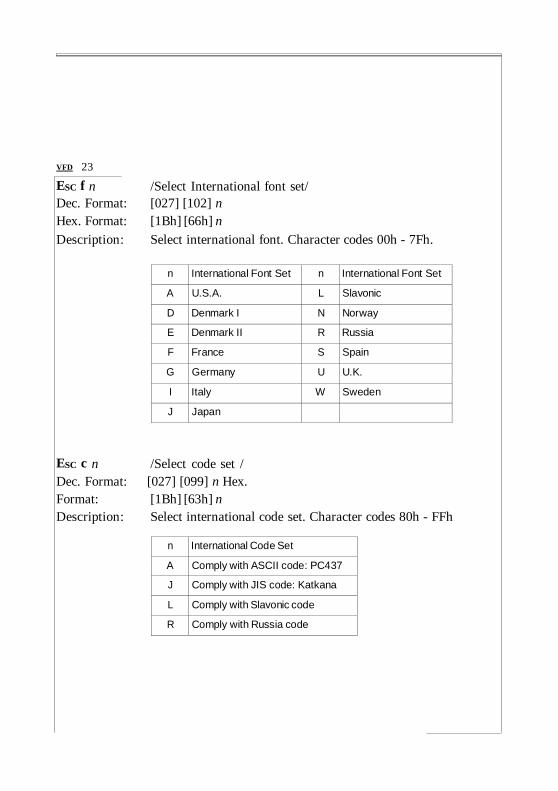
ESC f n /Select International font set/ Dec. Format: [027] [102] n Hex. Format: [1Bh] [66h] n Description: Select international font. Character codes 00h - 7Fh.
n International Font Set n International Font Set
A U.S.A. L Slavonic D Denmark I N Norway E Denmark II R Russia F France S Spain G Germany U U.K. I Italy W Sweden J Japan
ESC c n /Select code set / Dec. Format: [027] [099] n Hex. Format: [1Bh] [63h] n Description: Select international code set. Character codes 80h - FFh
n International Code Set A Comply with ASCII code: PC437 J Comply with JIS code: Katkana L Comply with Slavonic code R Comply with Russia code
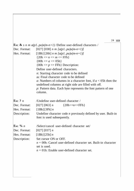
ESC & s n m a(p1..pa)x(m-n+1) /Define user-defined characters / Dec. Format: [027] [038] n m [a(p1..pa)x(m-n+1)] Hex. Format: [1Bh] [26h] n m [a(p1..pa)x(m-n+1)]
{20h <= n <= m <= FFh} {00h <= a <= 05h} {00h <= p <= FFh} Description: Define user-defined characters. n: Starting character code to be defined m: Final character code to be defined
24 VFD
a: Numbers of columns in a character font, if a < 05h then the undefined columns at right side are filled with off. p: Pattern data. Each byte represents the font pattern of one column.
ESC ? n /Undefine user-defined character / Dec. Format: [027] [063] n {20h<=n<=FFh} Hex. Format: [1Bh] [3Fh] n Description: Undefine character code n previously defined by user. Built-in
font is used subsequently.
ESC % n /Select/cancel user-defined character set/ Dec. Format: [027] [037] n Hex. Format: [1Bh] [25h] n Description: Set cursor ON or OFF.
n = 00h: Cancel user-defined character set. Built-in character set is used. n = 01h: Enable user-defined character set.

VFD 25
ESC s 1 /Store user-defined character in EEPROM/ Dec. Format: [027] [115] [001] Hex. Format: [1Bh] [7Fh] [01h] Description: This command is valid only if the display is in enable mode, as
set by Esc = command.
ESC d 1 /Restore user-defined character from EEPROM/ Dec. Format: [027] [100] [001] Hex. Format: [1Bh] [64h] [01h] Description: Restore user-defined character pattern that was previously
stored by Esc s 1 command.
ESC S n /Save current display data in EEPROM/ Dec. Format: [027] [083] n {31h<=n<=35h} Hex. Format: [1Bh] [53h] n Description: Store the current display image for future demo display.
n=31h: save image in layer 1. n=32h: save image in layer 2.
. . . n=35h: save image in layer 5.

ESC D n m /Display saved data from EEPROM/ Dec. Format: [027] [068] n m {01h <= n <= 1Fh} Hex. Format: [1Bh] [44h] n m {31h <= m <= 33h}
26 VFD
Description: The data saved by ESC S n can be displayed by this command. The layer to be displayed is selected by the bit position within the byte of n. For example, n=01h selects layer 1, n=02h selects layer 2, n=10h selects layer 5. More than one layer can be selected by specifying more than one bit to one in n, ie. n=05h selects layers one and three. When more than one layer is selected, they will be displayed in sequence. The parameter, M, sets the message animation method. There are two types, m=31h and m=32h. If m=33h, the two methods will be applied alternately.
ESC * n /Adjust brightness/ Dec. Format: Hex. Format:
[027] [042] n [1Bh] [2Ah] n
{01h <= n <= 04h}
Description: Adjust display brightness
ESC = n /Set output device mode/ Dec. Format: [027] [061] n {01h <= n <= 03h} Hex. Format: [1Bh] [3Dh] n Description: Set output device mode
n = 01h, display disable, next device enable n = 02h, display enable, next device disable n = 03h, display enable, next device enable
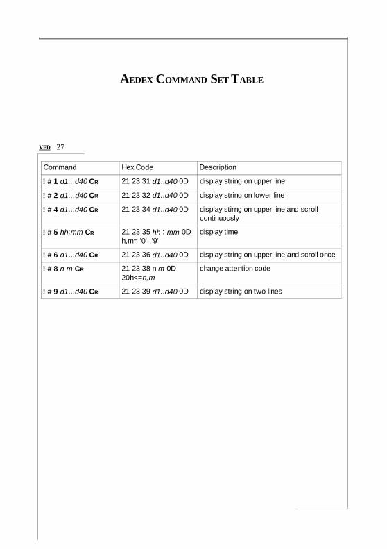
AEDEX COMMAND SET TABLE
VFD 27
Command Hex Code Description ! # 1 d1...d40 CR 21 23 31 d1..d40 0D display string on upper line ! # 2 d1...d40 CR 21 23 32 d1..d40 0D display string on lower line ! # 4 d1...d40 CR 21 23 34 d1..d40 0D display stirng on upper line and scroll
continuously ! # 5 hh:mm CR 21 23 35 hh : mm 0D
h,m= '0'..'9' display time
! # 6 d1...d40 CR 21 23 36 d1..d40 0D display string on upper line and scroll once
! # 8 n m CR 21 23 38 n m 0D 20h<=n,m
change attention code
! # 9 d1...d40 CR 21 23 39 d1..d40 0D display string on two lines

DSP800 COMMAND SET TABLE
28 VFD
Command Hex Code Description EOT SOH P n ETB 04 01 50 n 17
31h<=n<=58h move cursor to specified position
EOT SOH C n m ETB 04 01 43 n m 17 31h<=n<=m<=58h
clear display range from position n to position m and move cursor to position n
EOT SOH S n ETB 04 01 53 n 17 31h<=n<=35h
save current display data to n'th layer in EEPROM
EOT SOH D n m ETB 04 01 44 n m 17 01h<=n<=1Fh 31h<=m<=33h
display data saved in EEPROM. Bit position in n selects the layers to be displayed. Please see note below.
EOT SOH A n ETB 04 01 41 n 17 31h<=n<=34h
adjust brightness
EOT SOH F n ETB 04 01 46 n 17 00h<=n<=FFh
blink display
EOT SOH I n ETB 04 01 49 n 17 select international character set EOT SOH & n p1...p5 ETB
04 01 26 n p1..p5 17 20h<=n
define user-defined character
EOT SOH ? n ETB 04 01 3F n 17 20h<=n
delete user-defined character
EOT SOH = n ETB 04 01 3D n 17 n=1,2
select peripheral device. n=1: next device n=2: display
EOT SOH % ETB 04 01 25 17 initialize display EOT SOH @ ETB 04 01 40 17 self test
* When using display data saved in EEPROM command (EOT SOH D), the data layer is selected by the bit position within a byte in n. For example n=01h selects layer one, n=04h selects layer three, whereas n=05h selects bothe layer one and three. When more than one layer is selected, they will be
displayed in sequence.

EPSON COMMAND SET TABLE VFD 29
Command Hex Code Description HT 09 move cursor right BS 08 move cursor left US LF 1F 0A move cursor up LF 0A move cursor down US CR 1F 0D move cursor to right-end CR 0D move cursor to left-end HOM 0B move cursor to home position US B 1F 42 move cursor to bottom position US $ x y 1F 24 x y
01h<=x<=14h hy=01h, 02h
move cursor to position specified
CLR 0C clear display CAN 18 clear cursor line US C n 1F 43 n
n=00h, 01h set/cancel cursor display. n=0 hides cursor, n=1 displays cursor.
ESC t n 1B 74 n 01h<=n<=07h
select code table for character range 80h-FFh
ESC R n 1B 52 n 01h<=n<=0Fh
select international character set for character range 20h-7Fh
US r n 1F 72 n n=00h, 01h set/cancel reverse character US MD1 1F 01 set overwrite mode US MD2 1F 02 set vertical scroll mode US MD3 1F 03 set herizontal scroll mode ESC W n s x1 y1 x2 y2 1B 57 n s x1 y1 x2 y2
01h<=n<=04h s=00h, 01h 01h<=x1<=x2<=14h 01h<=y1<=y2<=14h
set/cancel window range

30 VFD
Command Hex Code Description ESC % n 1B 25 n n=00h, 01h select/cancel user-defined character set ESC & s n m [a(p1..pa)]x(m-n+1)
1B 26 01 n m ... [a(p1..p5)][m- n+1]
define user-defined character. 21h≦n≦m≦FFh ;a=5(p1..p5=pattern1..pattern5) ;00h<=p<=FFh
ESC ? 1B 3F delete user-defined character ESC s 1 1B 73 01 store user-defined characters in EEPROM ESC d 1 1B 64 01 load user-defined characters from EEPROM
US : 1F 3A set start/ending position of macro definition US ^ n m 1F 5E n m
00h<=n<=FFh 00h<=m<=FFh
execute then quit macro
US T h m 1F 54 h m 00h<=h<=23h 00h<=m<=59h
set and display time counter. The time is in hh:mm:ss format, displayed on the bottom right corner. Any command moving the cursor to the bottom line would disable the time display,
US U 1F 55 display the time counter at the bottom right corner. If the counter was not set previously with Us T command, its containt starts from the last time the display was initialized.
US E n 1F 45 n 01h<=n<=FFh
blink display in n x 50mS interval.
US X n 1F 58 n 01h<=n<=04h
adjust brightness
ESC @ 1B 40 initialize display US @ 1F 40 self test ESC = n 1B 3D n
n=01h, 02h, 03h select preipheral device n=01h: select next device n=02h: select display n=03h: select display and next device

VFD 31
International Font Set for Epson (20h-7Fh)
n International Font Set n International Font Set
0 U.S.A. 8 Japan 1 France 9 Norway 2 Germany A Denmark II 3 U.K. B Slavonic 4 Denmark I C Russia 5 Sweden D reserved 6 Italy E reserved 7 Spain F reserved
Code Table for Epson
n International Font Set (80h - FFh) 0 Page 0: PC437: U.S.A., standard Europe 1 Page 1: Katakana for Japan 2 Page 2: PC858: multilingual 3 Page 3: PC860: Portuguese 4 Page 4: PC863: Canadian-French 5 Page 5: PC865: Nordic 6 Page 6: Russia 7 Page 7: Slavonic 8 Page 8: PC866
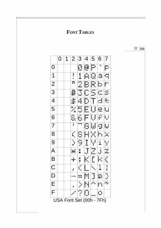
FONT TABLES
32 VFD
0 1 2
0 1 2
3 4 5 6 7
3 4 5 6 7 8 9 A B C D E F USA Font Set (00h - 7Fh)

VFD 33
n Country 23 24 40 5B 5C 5D 5E 60 7B 7C 7D 7E
0 USA
1 France
2 Germany
3 U.K.
4 Denmark I
5 Sweden
6 Italy
7 Spain
8 Japan
9 Norway
10 Denmark II
11 Slavonic
12 Russia
Font Variations (00h - 7Fh)

34 VFD
8 9 A B C D E F 8 9 A B C D E F
0 0 1 1 2 2 3 4 5 6 7 7 8 8 9 9 A A B B C D E F
PC-437 Font Set
C D E F
PC-858 Font Set

VFD 35
8 9 A B C D E F 8 9 A B C D E F 0 0 1 1 2 2 3 3 4 4 5 5 6 6 7 7 8 8 9 9 A A B B C C D D E F
PC-860 Font Set
E F
PC-863 Font Set
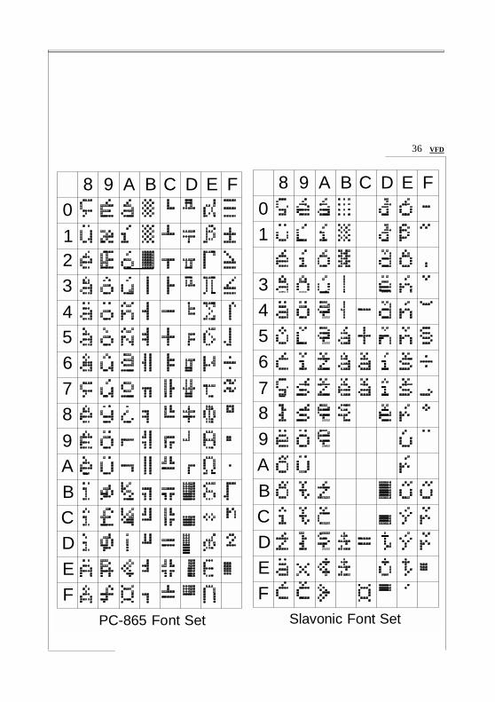
36 VFD
8 9 A B C D E F 8 9 A B C D E F
0 0 1 1 2 3 3 4 4 5 5 6 6 7 7 8 8 9 9 A A B B C D E F
PC-865 Font Set
C D E F
Slavonic Font Set

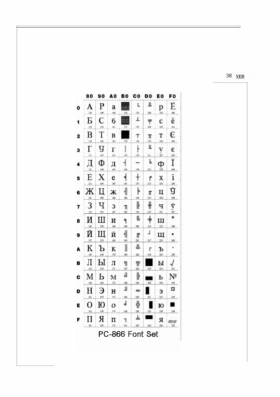
VFD 37
8 0 1 2 3
9 A B C D E F 8 9 A
0
1 2 3
B C D E F
4 4 5 5 6 6 7 7 8 9 A B C D E F
Russia Font Set
8 9 A
B C D E F
38 VFD