veto wall test hyupwoo lee minerva/jupiter group meeting feb, 13, 2008
Post on 19-Dec-2015
216 views
TRANSCRIPT

Veto Wall Test
Hyupwoo Lee
MINERvA/Jupiter Group MeetingFeb, 13, 2008

Noise problem in pedestal study

3
Pedestal
Use two different way for taking pedestal data - Pedestal Mode : without hit (Jesse’s note) - Discriminator Mode : with trigger hit (random
trigger) Pedestal - (board offset) + (board noise) + (PMT noise) Open channel : without PMT signal => only about
board PMT channel : with PMT signal (with 3-ch wire
divider) => board and PMT

4
Setup – 1 (TriP-t register setting)
Register # Trip Register Ped Discr1 IBP 100 1002 IBBNFoll 120 1203 IFF 0 04 IBPPIFF1REF 160 1605 IBPOPAMP 60 606 IBPFol2 24 247 IFFP2 0 428 IBCOMP 0 89 VREF 170 16010 VTH 0 17011 GAIN 8 811 PIPEDELAY 6 712 IRSEL 3 313 IWSEL 3 3
Pedestal Mode - Without hit - Without firing discri. - Same condition for real data?
Discriminator Mode - Need trigger hit - Use random trigger - Almost same condition for real
data - Need more time for all channel - I will choose this mode for futu
re pedestal data taking

5
Setup – 2

6
Open & PMT 1(same channel – discri. mode)
Gaussian fit with selected interval
Gaussian fit with whole interval
This tail makes problem

7
Where the noise comes from? - Lots of pain for me
Light leakage?- I tried with turning HV off : the same noise appears.
Noisy HV supply?- I tried to disconnect HV supply : the same noise appears.
Noisy PMT circuit?- I tried with the other PMTs (from the small panels and opposite side PMT) : the same noise appears.
Floating ground?- I checked all, found a floating ground from low voltage supply, and fixed it : the same noise appears.
I found something wrong with high-gain.

8
Double peak at high-gain No signal input for all 16 channel
s All high-gain channels have doub
le peak problem. Their correlation seems like phas
e related something. (Paul has not seen yet this correlation.)
Paul suspects that the noise comes from PC via signal cable
Paul suggests to connect FEB’s ground to the other ground-stuff with thick grounding cable.

Ratio of ADC counts to Q

10
Setup – 1 (TriP-t register setting)
Register # Trip Register Value1 IBP 1002 IBBNFoll 1203 IFF 04 IBPPIFF1REF 1605 IBPOPAMP 606 IBPFol2 247 IFFP2 428 IBCOMP 89 VREF 16010 VTH 22011 GAIN 811 PIPEDELAY 712 IRSEL 313 IWSEL 3

11
Setup – 2 Square pulse(+) for circuit
varied from 0.5V to 5V (with 50 Ohm load)
Signal input varied from 0.5pC to ~5pC
RC time for signal input ~5ns Signal size : ~30pC(average)
from the scope calculation of the last summer research
Over than 5pC ?
- >100pF : RC time ?
- new combination of resistors (I will try)
- >5V square pulse (possible to 10V, I will try)

12
Setup – 3 (Signal timing)
Purple : GATE Blue : Charge injection square pulse Yellow : TRIG Time interval between square pulse edge and TRIG : ~50ns

13
Result - 1
Low-gain seems no problem but high-gain has the same double-peak problem
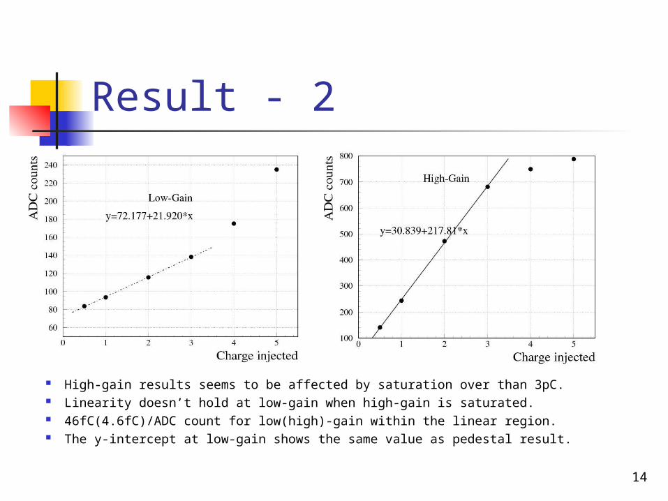
14
Result - 2
High-gain results seems to be affected by saturation over than 3pC. Linearity doesn’t hold at low-gain when high-gain is saturated. 46fC(4.6fC)/ADC count for low(high)-gain within the linear region. The y-intercept at low-gain shows the same value as pedestal result.