vespa would like to thank you well for a long time to come ... · vespa would like to thank you for...
TRANSCRIPT
Vespa would like to thank you
for choosing one of its products. We have prepared this manual to help you to get the very best from your vehicle. Please read it carefully before ridingthe vehicle for the first time. It contains information, tips and precautions for using your vehicle. It also describes features, details and devices to assureyou that you have made the right choice. We believe that if you follow our suggestions, you will soon get to know your new scooter and it will serve youwell for a long time to come. This booklet forms an integral part of the vehicle; should the vehicle be sold, it must be transferred to the new owner.
Vespa LX 125ie 150ie 3Valvole
Ed. 01_04/2012
The instructions given in this manual are intended to provide a clear, simple guide to using your vehicle; this booklet also details routine maintenanceprocedures and regular checks that should be carried out on the vehicle at an authorised Dealer or Service Centre. The booklet also containsinstructions for simple repairs. Any operations not specifically described in this booklet require the use of special tools and/or particular technicalknowledge: to carry out these operations, refer to any authorised Dealer or Service Centres.
2
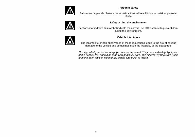
Personal safety
Failure to completely observe these instructions will result in serious risk of personalinjury.
Safeguarding the environment
Sections marked with this symbol indicate the correct use of the vehicle to prevent dam-aging the environment.
Vehicle intactness
The incomplete or non-observance of these regulations leads to the risk of seriousdamage to the vehicle and sometimes even the invalidity of the guarantee.
The signs that you see on this page are very important. They are used to highlight partsof the booklet that should be read with particular care. The different symbols are usedto make each topic in the manual simple and quick to locate.
3

4
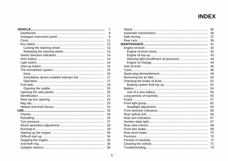
INDEX
VEHICLE...................................................................................... 7Dashboard................................................................................ 8Analogue instrument panel....................................................... 9Clock......................................................................................... 11Key switch................................................................................. 12
Locking the steering wheel.................................................... 13Releasing the steering wheel................................................ 13
Switch direction indicators........................................................ 14Horn button............................................................................... 14Light switch............................................................................... 14Start-up button.......................................................................... 15The immobilizer system............................................................ 15
Keys...................................................................................... 16Immobilizer device enabled indicator led.............................. 17Operation............................................................................... 17
Fuel tank................................................................................... 19Opening the saddle............................................................... 20
Opening the side panels........................................................... 20Identification.............................................................................. 21Rear top box opening................................................................ 23Bag clip..................................................................................... 23Helmet Anti-theft Device........................................................... 24
USE.............................................................................................. 25Checks...................................................................................... 26Refuelling.................................................................................. 26Tyre pressure............................................................................ 27Shock absorbers adjustment.................................................... 28Running in................................................................................. 29Starting up the engine............................................................... 30Difficult start up......................................................................... 34Stopping the engine.................................................................. 34Anti-theft ring............................................................................. 35Catalytic silencer....................................................................... 35
Stand......................................................................................... 36Automatic transmission............................................................. 36Safe driving............................................................................... 37Rear rack.................................................................................. 38
MAINTENANCE........................................................................... 41Engine oil level.......................................................................... 42
Engine oil level check............................................................ 42Engine oil top-up................................................................... 43Warning light (insufficient oil pressure)................................. 44Engine oil change.................................................................. 44
Hub oil level.............................................................................. 46Tyres......................................................................................... 48Spark plug dismantlement........................................................ 49Removing the air filter............................................................... 50Checking the brake oil level...................................................... 51
Braking system fluid top up................................................... 51Battery....................................................................................... 54
Use of a new battery............................................................. 55Long periods of inactivity.......................................................... 55Fuses........................................................................................ 57Front light group........................................................................ 62
Headlight adjustment............................................................. 64Front direction indicators........................................................... 65Rear optical unit........................................................................ 66Rear turn indicators................................................................... 67Number plate light..................................................................... 67Rear-view mirrors...................................................................... 68Front disc brake........................................................................ 69Rear drum brake....................................................................... 70Puncture.................................................................................... 70Periods of inactivity................................................................... 71Cleaning the vehicle.................................................................. 71Troubleshooting........................................................................ 73
5
TECHNICAL DATA...................................................................... 77Data.......................................................................................... 78Toolkit....................................................................................... 83
SPARE PARTS AND ACCESSORIES........................................ 85Warnings................................................................................... 86
SCHEDULED MAINTENANCE.................................................... 87Scheduled servicing table......................................................... 88
6
Vespa LX 125ie 150ie 3Valvole
Chap. 01Vehicle
7
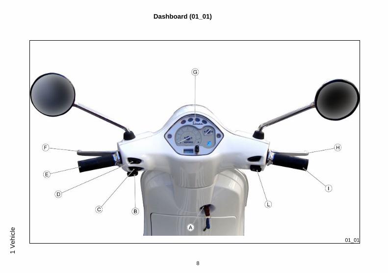
Dashboard (01_01)
01_01
8
1 Ve
hicl
e
A = Ignition key-switch
B = Horn button
C = Turn indicator switch
D = Light switches
E = Left hand grip
F = Rear brake control lever
G = Analogue instrument panel
H = Front brake control lever
I = Throttle grip
L = Start-up button
Analogue instrument panel (01_02)
9
1 Vehicle
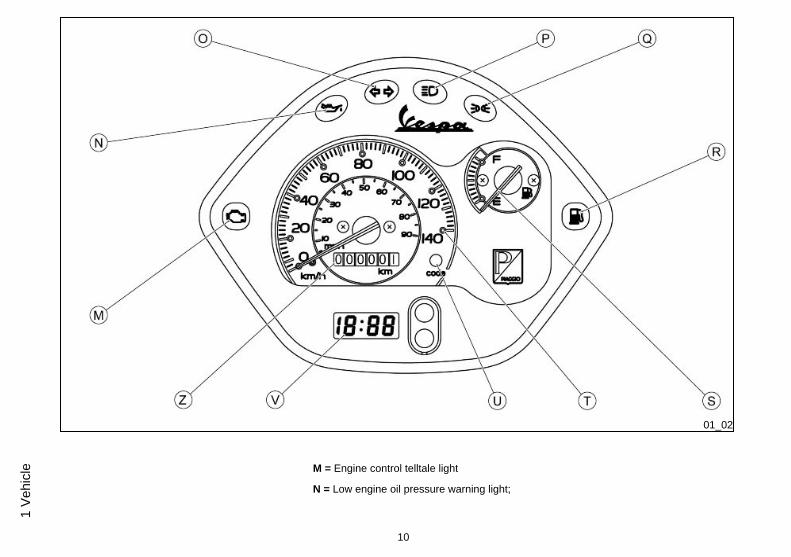
01_02
M = Engine control telltale light
N = Low engine oil pressure warning light;
10
1 Ve
hicl
e
O = Turn indicator warning light
P = High-beam warning light
Q = Daylight running light/low-beam light warning light
R =Low fuel warning light
S= = Fuel gauge
T = Speedometer
U = = Immobilizer LED warning light
V = Digital clock
Z = Odometer
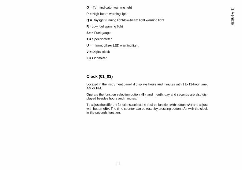
Clock (01_03)
Located in the instrument panel, it displays hours and minutes with 1 to 12-hour time,AM or PM.
Operate the function selection button «B» and month, day and seconds are also dis-played besides hours and minutes.
To adjust the different functions, select the desired function with button «A» and adjustwith button «B». The time counter can be reset by pressing button «A» with the clockin the seconds function.
11
1 Vehicle
01_03
The digital clock is powered by a battery (battery life is about 2 years); lift the wholeinstrument panel to replace the battery. It is advisable to take your vehicle to anAuthorised Service Centre for this operation.
WARNING
DEAD BATTERIES ARE HARMFUL TO THE ENVIRONMENT. THEY MUST DIS-POSED OF IN SUITABLE CONTAINERS AS PRESCRIBED BY THE REGULA-TIONS IN FORCE.
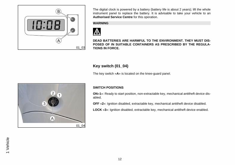
Key switch (01_04)
The key switch «A» is located on the knee-guard panel.
01_04
SWITCH POSITIONS
ON«1»: Ready to start position, non-extractable key, mechanical antitheft device dis-abled.
OFF «2»: Ignition disabled, extractable key, mechanical antitheft device disabled.
LOCK «3»: Ignition disabled, extractable key, mechanical antitheft device enabled.
12
1 Ve
hicl
e
01_05
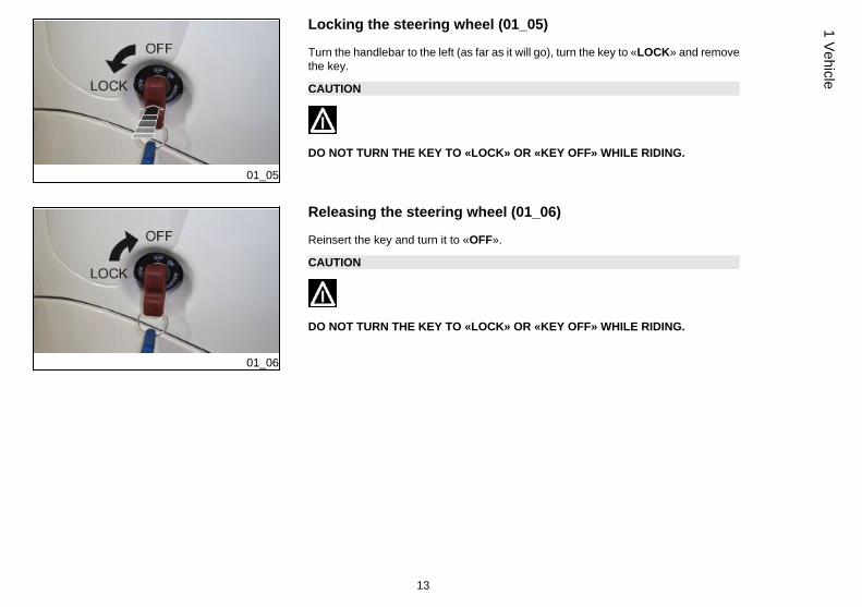
Locking the steering wheel (01_05)
Turn the handlebar to the left (as far as it will go), turn the key to «LOCK» and removethe key.
CAUTION
DO NOT TURN THE KEY TO «LOCK» OR «KEY OFF» WHILE RIDING.
01_06
Releasing the steering wheel (01_06)
Reinsert the key and turn it to «OFF».
CAUTION
DO NOT TURN THE KEY TO «LOCK» OR «KEY OFF» WHILE RIDING.
13
1 Vehicle
01_07
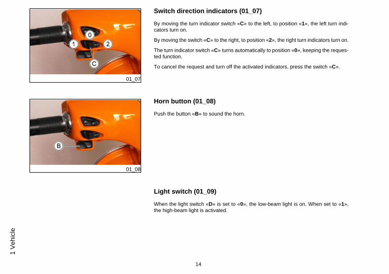
Switch direction indicators (01_07)
By moving the turn indicator switch «C» to the left, to position «1», the left turn indi-cators turn on.
By moving the switch «C» to the right, to position «2», the right turn indicators turn on.
The turn indicator switch «C» turns automatically to position «0», keeping the reques-ted function.
To cancel the request and turn off the activated indicators, press the switch «C».
01_08
Horn button (01_08)
Push the button «B» to sound the horn.
Light switch (01_09)
When the light switch «D» is set to «0», the low-beam light is on. When set to «1»,the high-beam light is activated.
14
1 Ve
hicl
e
01_09
CAUTION
DO NOT PLACE, TRANSPORT OBJECTS AND/OR CLOTHES OVER THE FRONTHEADLIGHT ASSEMBLY, WHEN THE HEADLIGHT IS TURNED ON OR OFF.FAILURE TO FOLLOW THIS PRECAUTION MAY CAUSE OVERHEATING ANDTHE SUBSEQUENT FUSION OF THE GLASS.
01_10
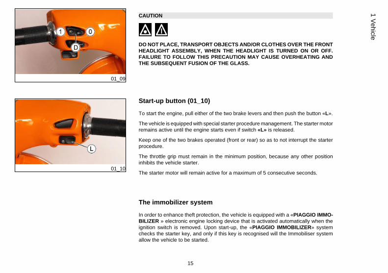
Start-up button (01_10)
To start the engine, pull either of the two brake levers and then push the button «L».
The vehicle is equipped with special starter procedure management. The starter motorremains active until the engine starts even if switch «L» is released.
Keep one of the two brakes operated (front or rear) so as to not interrupt the starterprocedure.
The throttle grip must remain in the minimum position, because any other positioninhibits the vehicle starter.
The starter motor will remain active for a maximum of 5 consecutive seconds.
The immobilizer system
In order to enhance theft protection, the vehicle is equipped with a «PIAGGIO IMMO-BILIZER » electronic engine locking device that is activated automatically when theignition switch is removed. Upon start-up, the «PIAGGIO IMMOBILIZER» systemchecks the starter key, and only if this key is recognised will the Immobiliser systemallow the vehicle to be started.
15
1 Vehicle
01_11
01_12
01_13
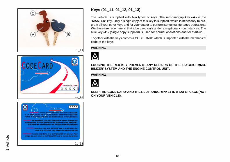
Keys (01_11, 01_12, 01_13)
The vehicle is supplied with two types of keys. The red-handgrip key «A» is the"MASTER" key. Only a single copy of this key is supplied, which is necessary to pro-gram all your other keys and for your dealer to perform some maintenance operations.We therefore recommend that it be used only under exceptional circumstances. Theblue key «B» (single copy supplied) is used for normal operations and for start-up.
Together with the keys comes a CODE CARD which is imprinted with the mechanicalcode of the keys.
WARNING
LOOSING THE RED KEY PREVENTS ANY REPAIRS OF THE 'PIAGGIO IMMO-BILIZER' SYSTEM AND THE ENGINE CONTROL UNIT.
WARNING
KEEP THE 'CODE CARD' AND THE RED HANDGRIP KEY IN A SAFE PLACE (NOTON YOUR VEHICLE).
16
1 Ve
hicl
e
01_14
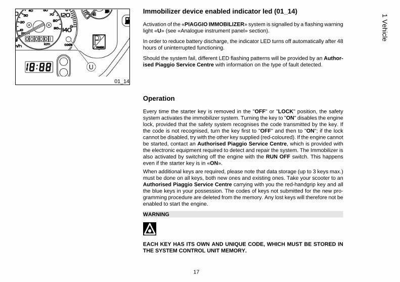
Immobilizer device enabled indicator led (01_14)
Activation of the «PIAGGIO IMMOBILIZER» system is signalled by a flashing warninglight «U» (see «Analogue instrument panel» section).
In order to reduce battery discharge, the indicator LED turns off automatically after 48hours of uninterrupted functioning.
Should the system fail, different LED flashing patterns will be provided by an Author-ised Piaggio Service Centre with information on the type of fault detected.
Operation
Every time the starter key is removed in the "OFF" or "LOCK" position, the safetysystem activates the immobilizer system. Turning the key to "ON" disables the enginelock, provided that the safety system recognises the code transmitted by the key. Ifthe code is not recognised, turn the key first to "OFF" and then to "ON"; if the lockcannot be disabled, try with the other key supplied (red-coloured). If the engine cannotbe started, contact an Authorised Piaggio Service Centre, which is provided withthe electronic equipment required to detect and repair the system. The Immobilizer isalso activated by switching off the engine with the RUN OFF switch. This happenseven if the starter key is in «ON».When additional keys are required, please note that data storage (up to 3 keys max.)must be done on all keys, both new ones and existing ones. Take your scooter to anAuthorised Piaggio Service Centre carrying with you the red-handgrip key and allthe blue keys in your possession. The codes of keys not submitted for the new pro-gramming procedure are deleted from the memory. Any lost keys will therefore not beenabled to start the engine.
WARNING
EACH KEY HAS ITS OWN AND UNIQUE CODE, WHICH MUST BE STORED INTHE SYSTEM CONTROL UNIT MEMORY.
17
1 Vehicle
VIOLENT SHOCKS MAY AFFECT THE ELECTRONIC COMPONENTS OF THEKEY.
IF OWNERSHIP OF THE VEHICLE IS TRANSFERRED TO ANOTHER PERSON,THE KEY WITH THE RED GRIP (AS WELL AS THE OTHER KEYS) AND THE"CODE CARD" MUST BE ALSO TRANSFERRED TO THE NEW OWNER.
Procedure start - red key
Insert the red ignition key in the switch key (in "OFF" position) and turn it to "ON". After1 - 3 seconds, turn the key to «OFF » again and pull it out.
Intermediate step - blu key
Within ten seconds after pulling out the red key, insert the black key and promptly turnit to «ON». After 1-3 seconds, turn the key to "OFF" again and pull it out.
In this way, a maximum of 3 blue keys can be programmed by repeating the aboveprocedure and keeping the indicated times.
Final step - red key
After extracting the last blue key, insert the brown key again and turn it to «ON» (carryout this operation within 10 seconds after extracting the previous key). Leave it in thisposition for 1 to 3 seconds and return it to «OFF».
18
1 Ve
hicl
e
Proper programming check
Insert the red key disabling the transponder (i.e., tilt the key cap by 90°) and turn thekey to "ON". Perform the engine start-up operation. Ensure that the engine does notstart. Insert the blue key and repeat the start-up operation. Check that engine starts.
WARNING
SHOULD THE ENGINE START WITH THE RED KEY (WITH TRANSPONDER OFF),OR IN THE EVENT OF WRONG OPERATION DURING PROGRAMMING, REPEATTHE PROCEDURE FROM THE BEGINNING.
01_15
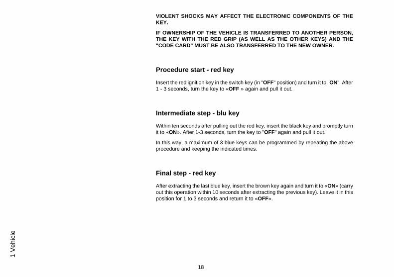
Fuel tank (01_15)
The fuel tank cap «A» is under the saddle. To reach it, tip the saddle forwards.
19
1 Vehicle
01_16
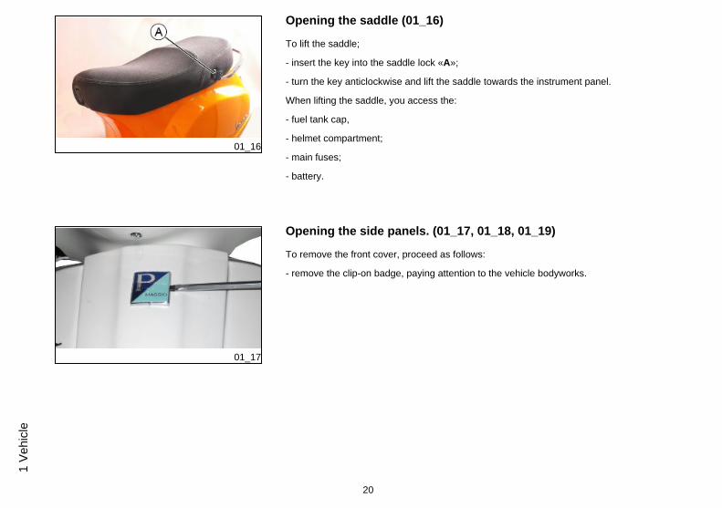
Opening the saddle (01_16)
To lift the saddle;
- insert the key into the saddle lock «A»;
- turn the key anticlockwise and lift the saddle towards the instrument panel.
When lifting the saddle, you access the:
- fuel tank cap,
- helmet compartment;
- main fuses;
- battery.
01_17
Opening the side panels. (01_17, 01_18, 01_19)
To remove the front cover, proceed as follows:
- remove the clip-on badge, paying attention to the vehicle bodyworks.
20
1 Ve
hicl
e
01_18
01_19
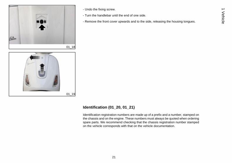
- Undo the fixing screw.
- Turn the handlebar until the end of one side.
- Remove the front cover upwards and to the side, releasing the housing tongues.
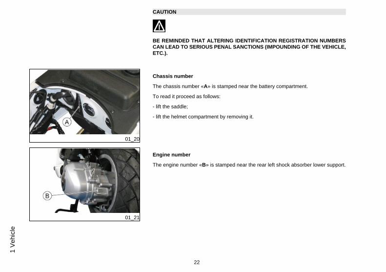
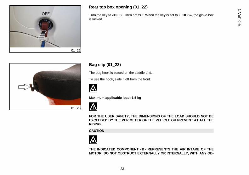
Identification (01_20, 01_21)
Identification registration numbers are made up of a prefix and a number, stamped onthe chassis and on the engine. These numbers must always be quoted when orderingspare parts. We recommend checking that the chassis registration number stampedon the vehicle corresponds with that on the vehicle documentation.
21
1 Vehicle
CAUTION
BE REMINDED THAT ALTERING IDENTIFICATION REGISTRATION NUMBERSCAN LEAD TO SERIOUS PENAL SANCTIONS (IMPOUNDING OF THE VEHICLE,ETC.).
01_20
Chassis number
The chassis number «A» is stamped near the battery compartment.
To read it proceed as follows:
- lift the saddle;
- lift the helmet compartment by removing it.
01_21
Engine number
The engine number «B» is stamped near the rear left shock absorber lower support.
22
1 Ve
hicl
e
01_22
Rear top box opening (01_22)
Turn the key to «OFF». Then press it. When the key is set to «LOCK», the glove-boxis locked.
01_23
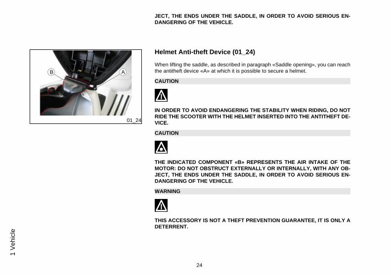
Bag clip (01_23)
The bag hook is placed on the saddle end.
To use the hook, slide it off from the front.
Maximum applicable load: 1.5 kg
FOR THE USER SAFETY, THE DIMENSIONS OF THE LOAD SHOULD NOT BEEXCEEDED BY THE PERIMETER OF THE VEHICLE OR PREVENT AT ALL THERIDING.
CAUTION
THE INDICATED COMPONENT «B» REPRESENTS THE AIR INTAKE OF THEMOTOR: DO NOT OBSTRUCT EXTERNALLY OR INTERNALLY, WITH ANY OB-
23
1 Vehicle
JECT, THE ENDS UNDER THE SADDLE, IN ORDER TO AVOID SERIOUS EN-DANGERING OF THE VEHICLE.
01_24
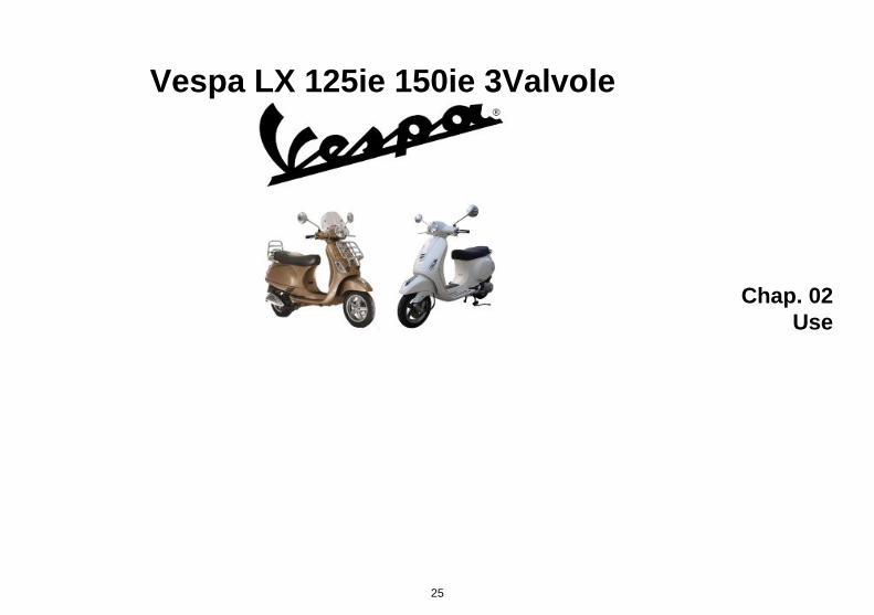
Helmet Anti-theft Device (01_24)
When lifting the saddle, as described in paragraph «Saddle opening», you can reachthe antitheft device «A» at which it is possible to secure a helmet.
CAUTION
IN ORDER TO AVOID ENDANGERING THE STABILITY WHEN RIDING, DO NOTRIDE THE SCOOTER WITH THE HELMET INSERTED INTO THE ANTITHEFT DE-VICE.
CAUTION
THE INDICATED COMPONENT «B» REPRESENTS THE AIR INTAKE OF THEMOTOR: DO NOT OBSTRUCT EXTERNALLY OR INTERNALLY, WITH ANY OB-JECT, THE ENDS UNDER THE SADDLE, IN ORDER TO AVOID SERIOUS EN-DANGERING OF THE VEHICLE.
WARNING
THIS ACCESSORY IS NOT A THEFT PREVENTION GUARANTEE, IT IS ONLY ADETERRENT.
24
1 Ve
hicl
e
Vespa LX 125ie 150ie 3Valvole
Chap. 02Use
25
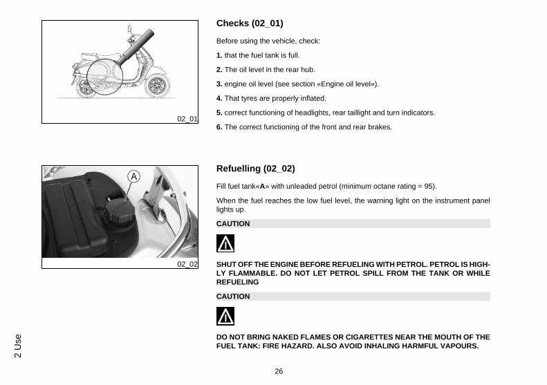
02_01
Checks (02_01)
Before using the vehicle, check:
1. that the fuel tank is full.
2. The oil level in the rear hub.
3. engine oil level (see section «Engine oil level»).
4. That tyres are properly inflated.
5. correct functioning of headlights, rear taillight and turn indicators.
6. The correct functioning of the front and rear brakes.
02_02
Refuelling (02_02)
Fill fuel tank«A» with unleaded petrol (minimum octane rating = 95).
When the fuel reaches the low fuel level, the warning light on the instrument panellights up.
CAUTION
SHUT OFF THE ENGINE BEFORE REFUELING WITH PETROL. PETROL IS HIGH-LY FLAMMABLE. DO NOT LET PETROL SPILL FROM THE TANK OR WHILEREFUELING
CAUTION
DO NOT BRING NAKED FLAMES OR CIGARETTES NEAR THE MOUTH OF THEFUEL TANK: FIRE HAZARD. ALSO AVOID INHALING HARMFUL VAPOURS.
26
2 U
se
CharacteristicFuel tank capacity
(8.2±0.5) l
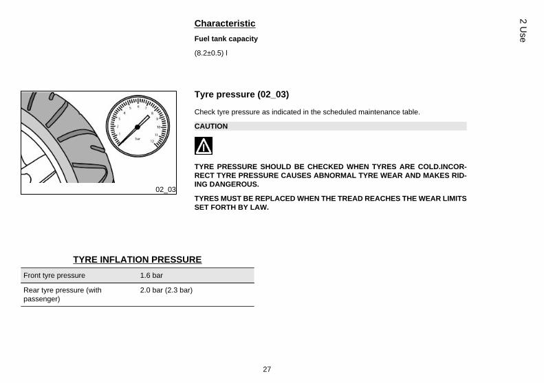
02_03
Tyre pressure (02_03)
Check tyre pressure as indicated in the scheduled maintenance table.
CAUTION
TYRE PRESSURE SHOULD BE CHECKED WHEN TYRES ARE COLD.INCOR-RECT TYRE PRESSURE CAUSES ABNORMAL TYRE WEAR AND MAKES RID-ING DANGEROUS.
TYRES MUST BE REPLACED WHEN THE TREAD REACHES THE WEAR LIMITSSET FORTH BY LAW.
TYRE INFLATION PRESSUREFront tyre pressure 1.6 bar
Rear tyre pressure (withpassenger)
2.0 bar (2.3 bar)
27
2 Use
TYRESFront tyre Tubeless, 110/70 - 11'' 45L
Rear tyre Tubeless, 120/70 - 10'' 54L
02_04
02_05
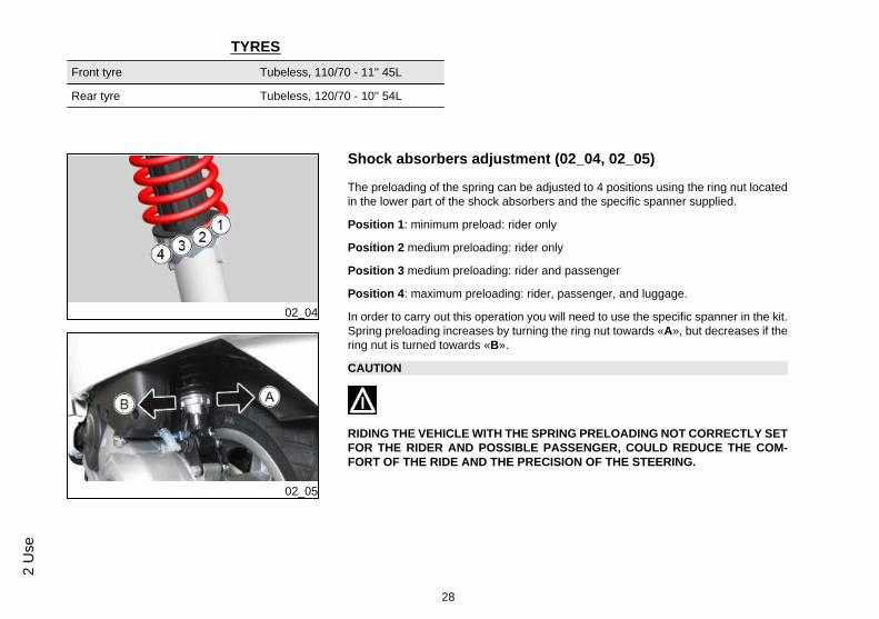
Shock absorbers adjustment (02_04, 02_05)
The preloading of the spring can be adjusted to 4 positions using the ring nut locatedin the lower part of the shock absorbers and the specific spanner supplied.
Position 1: minimum preload: rider only
Position 2 medium preloading: rider only
Position 3 medium preloading: rider and passenger
Position 4: maximum preloading: rider, passenger, and luggage.
In order to carry out this operation you will need to use the specific spanner in the kit.Spring preloading increases by turning the ring nut towards «A», but decreases if thering nut is turned towards «B».
CAUTION
RIDING THE VEHICLE WITH THE SPRING PRELOADING NOT CORRECTLY SETFOR THE RIDER AND POSSIBLE PASSENGER, COULD REDUCE THE COM-FORT OF THE RIDE AND THE PRECISION OF THE STEERING.
28
2 U
se
WARNING
WE RECOMMEND WEARING GLOVES WHILE CARRYING OUT THIS OPERA-TION IN ORDER TO AVOID INJURIES.
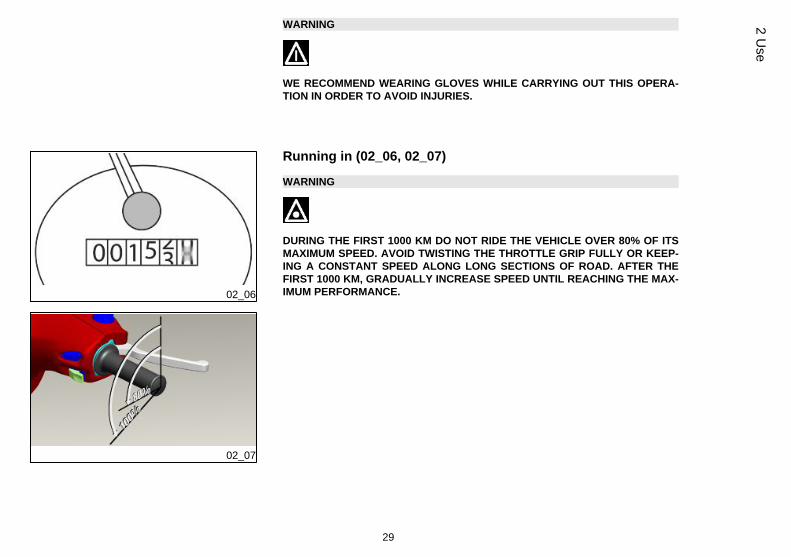
02_06
02_07
Running in (02_06, 02_07)
WARNING
DURING THE FIRST 1000 KM DO NOT RIDE THE VEHICLE OVER 80% OF ITSMAXIMUM SPEED. AVOID TWISTING THE THROTTLE GRIP FULLY OR KEEP-ING A CONSTANT SPEED ALONG LONG SECTIONS OF ROAD. AFTER THEFIRST 1000 KM, GRADUALLY INCREASE SPEED UNTIL REACHING THE MAX-IMUM PERFORMANCE.
29
2 Use
02_08
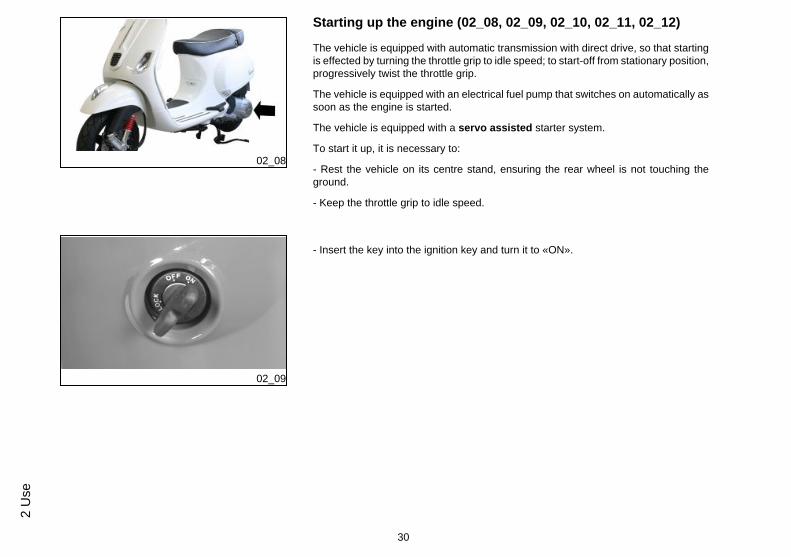
Starting up the engine (02_08, 02_09, 02_10, 02_11, 02_12)
The vehicle is equipped with automatic transmission with direct drive, so that startingis effected by turning the throttle grip to idle speed; to start-off from stationary position,progressively twist the throttle grip.
The vehicle is equipped with an electrical fuel pump that switches on automatically assoon as the engine is started.
The vehicle is equipped with a servo assisted starter system.
To start it up, it is necessary to:
- Rest the vehicle on its centre stand, ensuring the rear wheel is not touching theground.
- Keep the throttle grip to idle speed.
02_09
- Insert the key into the ignition key and turn it to «ON».
30
2 U
se
02_10
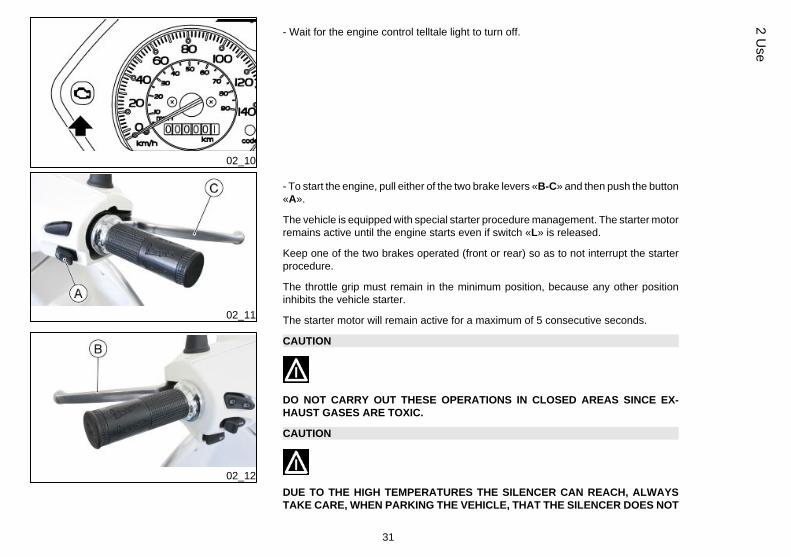
- Wait for the engine control telltale light to turn off.
02_11
02_12
- To start the engine, pull either of the two brake levers «B-C» and then push the button«A».
The vehicle is equipped with special starter procedure management. The starter motorremains active until the engine starts even if switch «L» is released.
Keep one of the two brakes operated (front or rear) so as to not interrupt the starterprocedure.
The throttle grip must remain in the minimum position, because any other positioninhibits the vehicle starter.
The starter motor will remain active for a maximum of 5 consecutive seconds.
CAUTION
DO NOT CARRY OUT THESE OPERATIONS IN CLOSED AREAS SINCE EX-HAUST GASES ARE TOXIC.
CAUTION
DUE TO THE HIGH TEMPERATURES THE SILENCER CAN REACH, ALWAYSTAKE CARE, WHEN PARKING THE VEHICLE, THAT THE SILENCER DOES NOT
31
2 Use
COME INTO CONTACT WITH FLAMMABLE MATERIALS, TO AVOID SERIOUSBURNS.
02_13
Starting up the engine (02_12, 02_13, 02_14, 02_15, 02_16,02_17)
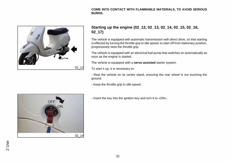
The vehicle is equipped with automatic transmission with direct drive, so that startingis effected by turning the throttle grip to idle speed; to start-off from stationary position,progressively twist the throttle grip.
The vehicle is equipped with an electrical fuel pump that switches on automatically assoon as the engine is started.
The vehicle is equipped with a servo assisted starter system.
To start it up, it is necessary to:
- Rest the vehicle on its centre stand, ensuring the rear wheel is not touching theground.
- Keep the throttle grip to idle speed.
02_14
- Insert the key into the ignition key and turn it to «ON».
32
2 U
se
02_15
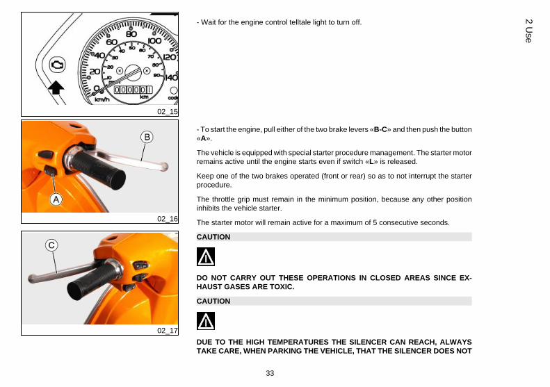
- Wait for the engine control telltale light to turn off.
02_16
02_17
- To start the engine, pull either of the two brake levers «B-C» and then push the button«A».
The vehicle is equipped with special starter procedure management. The starter motorremains active until the engine starts even if switch «L» is released.
Keep one of the two brakes operated (front or rear) so as to not interrupt the starterprocedure.
The throttle grip must remain in the minimum position, because any other positioninhibits the vehicle starter.
The starter motor will remain active for a maximum of 5 consecutive seconds.
CAUTION
DO NOT CARRY OUT THESE OPERATIONS IN CLOSED AREAS SINCE EX-HAUST GASES ARE TOXIC.
CAUTION
DUE TO THE HIGH TEMPERATURES THE SILENCER CAN REACH, ALWAYSTAKE CARE, WHEN PARKING THE VEHICLE, THAT THE SILENCER DOES NOT
33
2 Use
COME INTO CONTACT WITH FLAMMABLE MATERIALS, TO AVOID SERIOUSBURNS.
02_18
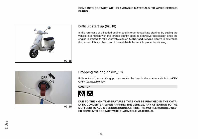
Difficult start up (02_18)
In the rare case of a flooded engine, and in order to facilitate starting, try putting thevehicle into motion with the throttle slightly open. It is however necessary, once theengine is started, to take your vehicle to an Authorised Service Centre to determinethe cause of this problem and to re-establish the vehicle proper functioning.
02_19
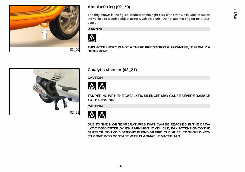
Stopping the engine (02_19)
Fully untwist the throttle grip, then rotate the key in the starter switch to «KEYOFF» (extractable key).
CAUTION
DUE TO THE HIGH TEMPERATURES THAT CAN BE REACHED IN THE CATA-LYTIC CONVERTER, WHEN PARKING THE VEHICLE, PAY ATTENTION TO THEMUFFLER: TO AVOID SERIOUS BURNS OR FIRE, THE MUFFLER SHOULD NEV-ER COME INTO CONTACT WITH FLAMMABLE MATERIALS.
34
2 U
se
02_20
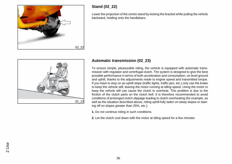
Anti-theft ring (02_20)
The ring shown in the figure, located on the right side of the vehicle is used to fastenthe vehicle to a stable object using a vehicle chain. Do not use the ring for other pur-poses.
WARNING
THIS ACCESSORY IS NOT A THEFT PREVENTION GUARANTEE, IT IS ONLY ADETERRENT.
02_21
Catalytic silencer (02_21)
CAUTION
TAMPERING WITH THE CATALYTIC SILENCER MAY CAUSE SEVERE DAMAGETO THE ENGINE.
CAUTION
DUE TO THE HIGH TEMPERATURES THAT CAN BE REACHED IN THE CATA-LYTIC CONVERTER, WHEN PARKING THE VEHICLE, PAY ATTENTION TO THEMUFFLER: TO AVOID SERIOUS BURNS OR FIRE, THE MUFFLER SHOULD NEV-ER COME INTO CONTACT WITH FLAMMABLE MATERIALS.
35
2 Use
02_22
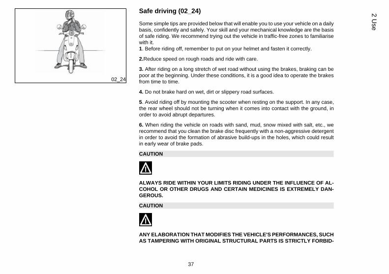
Stand (02_22)
Lower the projection of the centre stand by kicking the bracket while pulling the vehiclebackward, holding onto the handlebars.
02_23
Automatic transmission (02_23)
To ensure simple, pleasurable riding, the vehicle is equipped with automatic trans-mission with regulator and centrifugal clutch. The system is designed to give the bestpossible performance in terms of both acceleration and consumption, on level groundand uphill, thanks to the adjustments made to engine speed and transmitted torque.If you have to stop on an uphill slope (traffic lights, traffic jam, etc.) only use the braketo keep the vehicle still, leaving the motor running at idling speed. Using the motor tokeep the vehicle still can cause the clutch to overheat. This problem is due to thefriction of the clutch parts on the clutch bell. It is therefore recommended to avoidconditions of prolonged clutch slippage leading to clutch overheating (for example, aswell as the situation described above, riding uphill fully laden on steep slopes or start-ing off on slopes greater than 25%, etc.):
1. Do not continue riding in such conditions.
2. Let the clutch cool down with the motor at idling speed for a few minutes
36
2 U
se
02_24
Safe driving (02_24)
Some simple tips are provided below that will enable you to use your vehicle on a dailybasis, confidently and safely. Your skill and your mechanical knowledge are the basisof safe riding. We recommend trying out the vehicle in traffic-free zones to familiarisewith it.1. Before riding off, remember to put on your helmet and fasten it correctly.
2.Reduce speed on rough roads and ride with care.
3. After riding on a long stretch of wet road without using the brakes, braking can bepoor at the beginning. Under these conditions, it is a good idea to operate the brakesfrom time to time.
4. Do not brake hard on wet, dirt or slippery road surfaces.
5. Avoid riding off by mounting the scooter when resting on the support. In any case,the rear wheel should not be turning when it comes into contact with the ground, inorder to avoid abrupt departures.
6. When riding the vehicle on roads with sand, mud, snow mixed with salt, etc., werecommend that you clean the brake disc frequently with a non-aggressive detergentin order to avoid the formation of abrasive build-ups in the holes, which could resultin early wear of brake pads.
CAUTION
ALWAYS RIDE WITHIN YOUR LIMITS RIDING UNDER THE INFLUENCE OF AL-COHOL OR OTHER DRUGS AND CERTAIN MEDICINES IS EXTREMELY DAN-GEROUS.
CAUTION
ANY ELABORATION THAT MODIFIES THE VEHICLE'S PERFORMANCES, SUCHAS TAMPERING WITH ORIGINAL STRUCTURAL PARTS IS STRICTLY FORBID-
37
2 Use
DEN BY LAW, AND RENDERS THE VEHICLE NO LONGER CONFORMING TOTHE APPROVED TYPE AND DANGEROUS FOR RIDING.
CAUTION
DO NOT ADJUST THE MIRRORS WHILE RIDING. THIS COULD CAUSE YOU TOLOOSE CONTROL OF THE VEHICLE.
WARNING
IN ORDER TO PREVENT ANY ACCIDENTS RIDE VERY CAREFULLY AFTERADDING ACCESSORIES AND WHILE CARRYING LUGGAGE. THE ADDITION OFACCESSORIES AND LUGGAGE CAN REDUCE YOUR SCOOTER STABILITYAND PERFORMANCE, AS WELL AS THE LEVEL OF SAFETY DURING USE. (SEETHE «SPARE PARTS AND ACCESSORIES» SECTION)
02_25
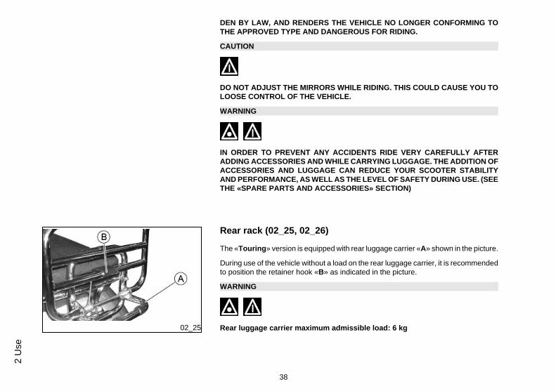
Rear rack (02_25, 02_26)
The «Touring» version is equipped with rear luggage carrier «A» shown in the picture.
During use of the vehicle without a load on the rear luggage carrier, it is recommendedto position the retainer hook «B» as indicated in the picture.
WARNING
Rear luggage carrier maximum admissible load: 6 kg
38
2 U
se
02_26
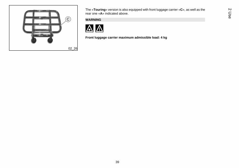
The «Touring» version is also equipped with front luggage carrier «C», as well as therear one «A» indicated above.
WARNING
Front luggage carrier maximum admissible load: 4 kg
39
2 Use

40
2 U
se

Vespa LX 125ie 150ie 3Valvole
Chap. 03Maintenance
41
Engine oil level
In four stroke engines, the engine oil is used to lubricate the timing elements, the benchbearings and the thermal group. An insufficient quantity of oil can cause seriousdamage to the engine. In all four-stroke engines, a loss of efficiency in oil perform-ance and consumption should be considered normal.
Consumption can particularly reflect the conditions of use (i.e when driving e.g.: usingthe vehicle most of the time with the throttle grip mainly open, means a higher oilconsumption).
In order to avoid problems, it is advisable to control oil level every time thevehicle is used.
03_01
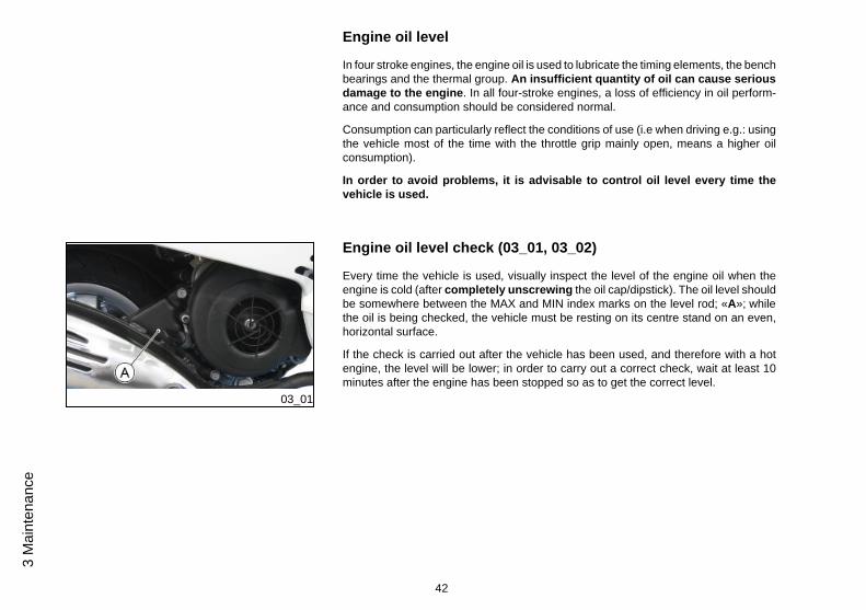
Engine oil level check (03_01, 03_02)
Every time the vehicle is used, visually inspect the level of the engine oil when theengine is cold (after completely unscrewing the oil cap/dipstick). The oil level shouldbe somewhere between the MAX and MIN index marks on the level rod; «A»; whilethe oil is being checked, the vehicle must be resting on its centre stand on an even,horizontal surface.
If the check is carried out after the vehicle has been used, and therefore with a hotengine, the level will be lower; in order to carry out a correct check, wait at least 10minutes after the engine has been stopped so as to get the correct level.
42
3 M
aint
enan
ce
03_02
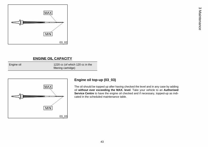
ENGINE OIL CAPACITYEngine oil 1220 cc (of which 120 cc in the
filtering cartridge)
03_03
Engine oil top-up (03_03)
The oil should be topped up after having checked the level and in any case by addingoil without ever exceeding the MAX. level. Take your vehicle to an AuthorisedService Centre to have the engine oil checked and if necessary, topped-up as indi-cated in the scheduled maintenance table.
43
3 Maintenance
03_04
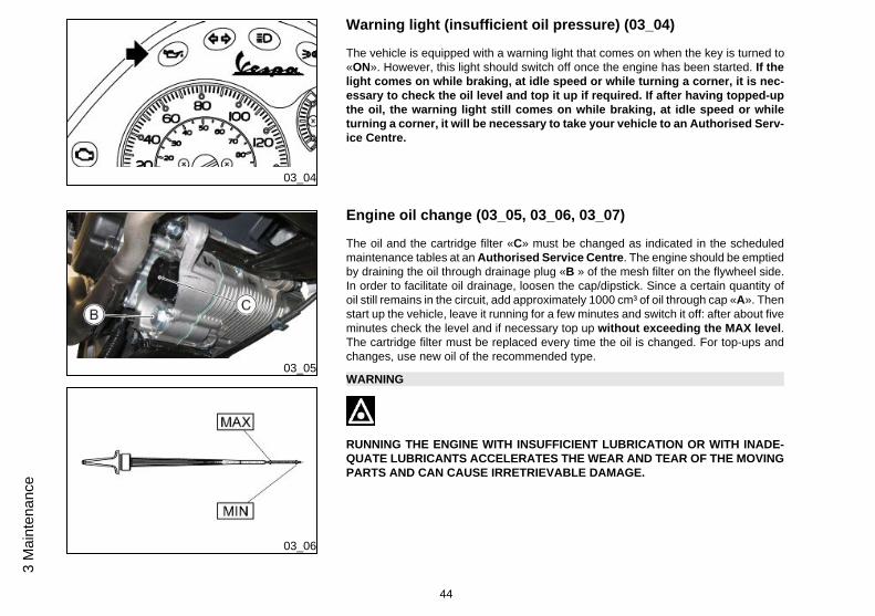
Warning light (insufficient oil pressure) (03_04)
The vehicle is equipped with a warning light that comes on when the key is turned to«ON». However, this light should switch off once the engine has been started. If thelight comes on while braking, at idle speed or while turning a corner, it is nec-essary to check the oil level and top it up if required. If after having topped-upthe oil, the warning light still comes on while braking, at idle speed or whileturning a corner, it will be necessary to take your vehicle to an Authorised Serv-ice Centre.
03_05
03_06
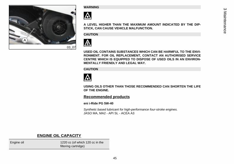
Engine oil change (03_05, 03_06, 03_07)
The oil and the cartridge filter «C» must be changed as indicated in the scheduledmaintenance tables at an Authorised Service Centre. The engine should be emptiedby draining the oil through drainage plug «B » of the mesh filter on the flywheel side.In order to facilitate oil drainage, loosen the cap/dipstick. Since a certain quantity ofoil still remains in the circuit, add approximately 1000 cm³ of oil through cap «A». Thenstart up the vehicle, leave it running for a few minutes and switch it off: after about fiveminutes check the level and if necessary top up without exceeding the MAX level.The cartridge filter must be replaced every time the oil is changed. For top-ups andchanges, use new oil of the recommended type.
WARNING
RUNNING THE ENGINE WITH INSUFFICIENT LUBRICATION OR WITH INADE-QUATE LUBRICANTS ACCELERATES THE WEAR AND TEAR OF THE MOVINGPARTS AND CAN CAUSE IRRETRIEVABLE DAMAGE.
44
3 M
aint
enan
ce
03_07
WARNING
A LEVEL HIGHER THAN THE MAXIMUM AMOUNT INDICATED BY THE DIP-STICK, CAN CAUSE VEHICLE MALFUNCTION.
CAUTION
USED OIL CONTAINS SUBSTANCES WHICH CAN BE HARMFUL TO THE ENVI-RONMENT. FOR OIL REPLACEMENT, CONTACT AN AUTHORISED SERVICECENTRE WHICH IS EQUIPPED TO DISPOSE OF USED OILS IN AN ENVIRON-MENTALLY FRIENDLY AND LEGAL WAY.
CAUTION
USING OILS OTHER THAN THOSE RECOMMENDED CAN SHORTEN THE LIFEOF THE ENGINE.
Recommended productseni i-Ride PG 5W-40
Synthetic based lubricant for high-performance four-stroke engines.JASO MA, MA2 - API SL - ACEA A3
ENGINE OIL CAPACITYEngine oil 1220 cc (of which 120 cc in the
filtering cartridge)
45
3 Maintenance
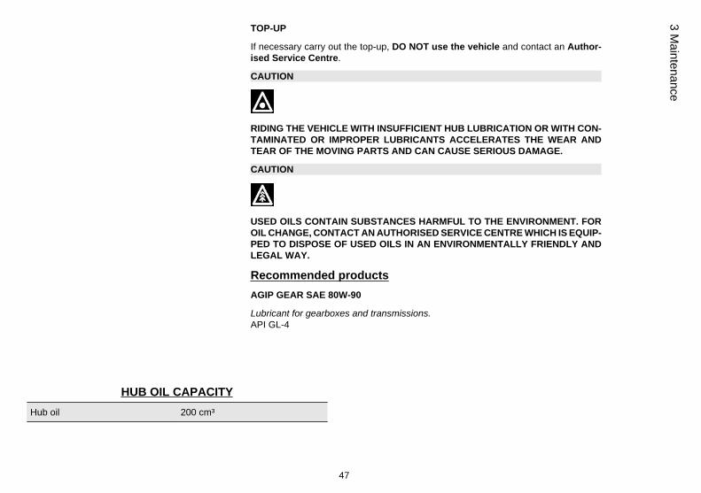
Hub oil level (03_08)
Check the presence of oil in the hub, according to the regular controls shown in thetable of the scheduled maintenance.
WARNING
FOR THE REGULAR CHECK OF THE HUB OIL LEVEL SHOWN IN THE SCHED-ULED MAINTENANCE TABLE, CONTACT AN AUTHORISED SERVICE CENTRE.
FOR THE CONTROLS OF THE HUB OIL LEVEL THAT ARE NOT PREDETER-MINED BY THE SCHEDULED MAINTENANCE TABLE, OPERATE AS DESCRI-BED.
03_08
CHECK LEVEL
- Park the vehicle on level ground and centre stand.
- Undo screw «A»:
• oil comes out of the screw hole «A»: the oil quantity in the hub is adequate;place it and tighten the screw.
• NO oil comes out of the screw hole «A»: the oil quantity in the hub, ISNOT adequate and it is necessary to carry out the top-up.
- With a cloth carefully clean the transmission crankcase.
WARNING
THE FUNCTION OF THE HUB WITH INSUFFICIENT HUB LUBRICATION OR WITHCONTAMINATED OR IMPROPER LUBRICANTS ACCELERATES THE WEARAND TEAR OF THE MOVING PARTS AND CAN CAUSE SERIOUS DAMAGE.
46
3 M
aint
enan
ce
TOP-UP
If necessary carry out the top-up, DO NOT use the vehicle and contact an Author-ised Service Centre.
CAUTION
RIDING THE VEHICLE WITH INSUFFICIENT HUB LUBRICATION OR WITH CON-TAMINATED OR IMPROPER LUBRICANTS ACCELERATES THE WEAR ANDTEAR OF THE MOVING PARTS AND CAN CAUSE SERIOUS DAMAGE.
CAUTION
USED OILS CONTAIN SUBSTANCES HARMFUL TO THE ENVIRONMENT. FOROIL CHANGE, CONTACT AN AUTHORISED SERVICE CENTRE WHICH IS EQUIP-PED TO DISPOSE OF USED OILS IN AN ENVIRONMENTALLY FRIENDLY ANDLEGAL WAY.
Recommended productsAGIP GEAR SAE 80W-90
Lubricant for gearboxes and transmissions.API GL-4
HUB OIL CAPACITYHub oil 200 cm³
47
3 Maintenance
03_09
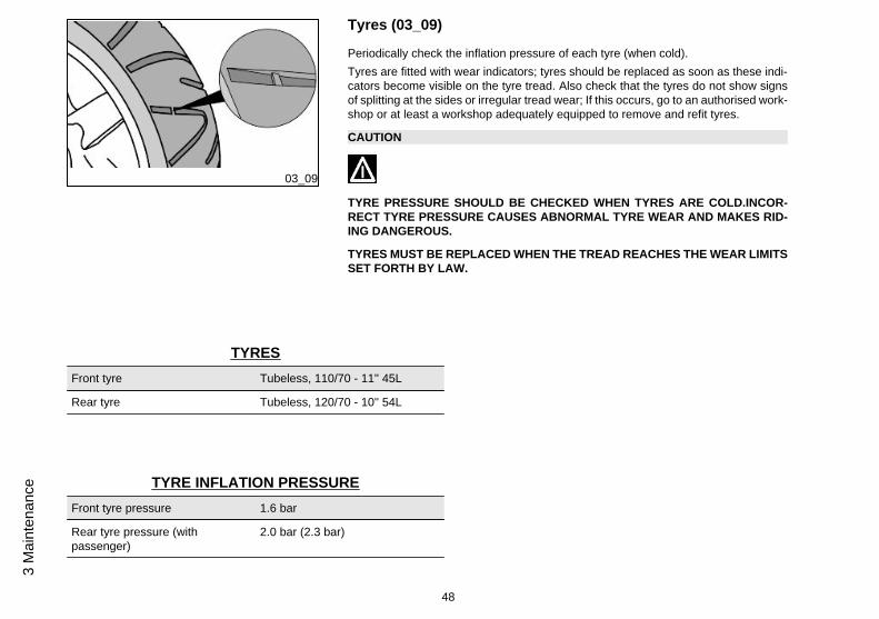
Tyres (03_09)
Periodically check the inflation pressure of each tyre (when cold).Tyres are fitted with wear indicators; tyres should be replaced as soon as these indi-cators become visible on the tyre tread. Also check that the tyres do not show signsof splitting at the sides or irregular tread wear; If this occurs, go to an authorised work-shop or at least a workshop adequately equipped to remove and refit tyres.
CAUTION
TYRE PRESSURE SHOULD BE CHECKED WHEN TYRES ARE COLD.INCOR-RECT TYRE PRESSURE CAUSES ABNORMAL TYRE WEAR AND MAKES RID-ING DANGEROUS.
TYRES MUST BE REPLACED WHEN THE TREAD REACHES THE WEAR LIMITSSET FORTH BY LAW.
TYRESFront tyre Tubeless, 110/70 - 11'' 45L
Rear tyre Tubeless, 120/70 - 10'' 54L
TYRE INFLATION PRESSUREFront tyre pressure 1.6 bar
Rear tyre pressure (withpassenger)
2.0 bar (2.3 bar)
48
3 M
aint
enan
ce
03_10
03_11
03_12
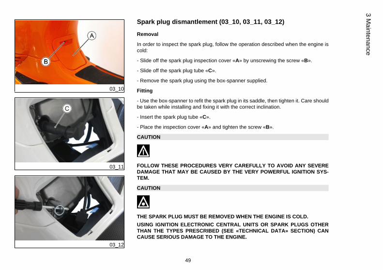
Spark plug dismantlement (03_10, 03_11, 03_12)
Removal
In order to inspect the spark plug, follow the operation described when the engine iscold:
- Slide off the spark plug inspection cover «A» by unscrewing the screw «B».
- Slide off the spark plug tube «C».
- Remove the spark plug using the box-spanner supplied.
Fitting
- Use the box-spanner to refit the spark plug in its saddle, then tighten it. Care shouldbe taken while installing and fixing it with the correct inclination.
- Insert the spark plug tube «C».
- Place the inspection cover «A» and tighten the screw «B».
CAUTION
FOLLOW THESE PROCEDURES VERY CAREFULLY TO AVOID ANY SEVEREDAMAGE THAT MAY BE CAUSED BY THE VERY POWERFUL IGNITION SYS-TEM.
CAUTION
THE SPARK PLUG MUST BE REMOVED WHEN THE ENGINE IS COLD.USING IGNITION ELECTRONIC CENTRAL UNITS OR SPARK PLUGS OTHERTHAN THE TYPES PRESCRIBED (SEE «TECHNICAL DATA» SECTION) CANCAUSE SERIOUS DAMAGE TO THE ENGINE.
49
3 Maintenance
CAUTION
PERFORM THE OPERATIONS CAREFULLY.DO NOT DAMAGE THE TONGUES OR THEIR SEATS. HANDLE THE PAINTEDAND PLASTIC COMPONENTS CAREFULLY. DO NOT SCRATCH OR DAMAGETHEM.
RECOMMENDED SPARK PLUGSpark plug (125cm³) NGK CR8EB
Spark plug (150cm³) NGK CR8EB
Electrode gap 0.7 to 0.8 mm
Removing the air filter
To remove and clean the air filter, follow the indications in the scheduled maintenancetable, contact an Authorised Service Centre.
50
3 M
aint
enan
ce
03_13
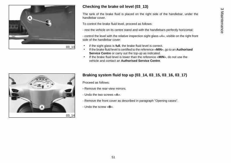
Checking the brake oil level (03_13)
The tank of the brake fluid is placed on the right side of the handlebar, under thehandlebar cover.
To control the brake fluid level, proceed as follows:
- rest the vehicle on its centre stand and with the handlebars perfectly horizontal;
- control the level with the relative inspection sight glass «A», visible on the right frontside of the handlebar cover:
• if the sight glass is full, the brake fluid level is correct.• If the brake fluid level is certified to the reference «MIN», go to an Authorised
Service Centre or carry out the top-up as indicated.• If the brake fluid level is lower than the reference «MIN», do not use the
vehicle and contact an Authorised Service Centre.
03_14
Braking system fluid top up (03_14, 03_15, 03_16, 03_17)
Proceed as follows:
- Remove the rear-view mirrors.
- Undo the two screws «A».
- Remove the front cover as described in paragraph "Opening cases".
- Undo the screw «B».
51
3 Maintenance
03_15
03_16
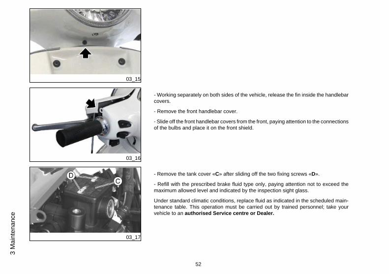
- Working separately on both sides of the vehicle, release the fin inside the handlebarcovers.
- Remove the front handlebar cover.
- Slide off the front handlebar covers from the front, paying attention to the connectionsof the bulbs and place it on the front shield.
03_17
- Remove the tank cover «C» after sliding off the two fixing screws «D».
- Refill with the prescribed brake fluid type only, paying attention not to exceed themaximum allowed level and indicated by the inspection sight glass.
Under standard climatic conditions, replace fluid as indicated in the scheduled main-tenance table. This operation must be carried out by trained personnel; take yourvehicle to an authorised Service centre or Dealer.
52
3 M
aint
enan
ce
WARNING
ONLY USE DOT 4-CLASSIFIED BRAKE FLUID. BRAKE CIRCUIT FLUID IS VERYCORROSIVE; MAKE SURE THAT IT DOES NOT COME INTO CONTACT WITHTHE PAINTWORK.
CAUTION
AVOID CONTACT OF BRAKE FLUID WITH EYES, SKIN, AND CLOTHING. INCASE OF CONTACT, RINSE WITH WATER. THE BRAKING CIRCUIT FLUID ISHYGROSCOPIC, THAT IS, IT ABSORBS HUMIDITY FROM THE SURROUNDINGAIR. IF THE HUMIDITY IN THE BRAKING FLUID EXCEEDS A CERTAIN VALUE,IT WILL LEAD TO INEFFICIENT BRAKING. NEVER USE BRAKING FLUID KEPTIN CONTAINERS THAT HAVE ALREADY BEEN OPENED, OR PARTIALLY USED.
Recommended productsAGIP BRAKE 4
Brake fluid.Synthetic fluid SAE J 1703 -FMVSS 116 - DOT 3/4 - ISO 4925 - CUNA NC 956 DOT4
FITTING
To fit the removed components to access the brake fluid tank, work in reverse orderwhat is described in the instructions of this paragraph.
53
3 Maintenance
03_18
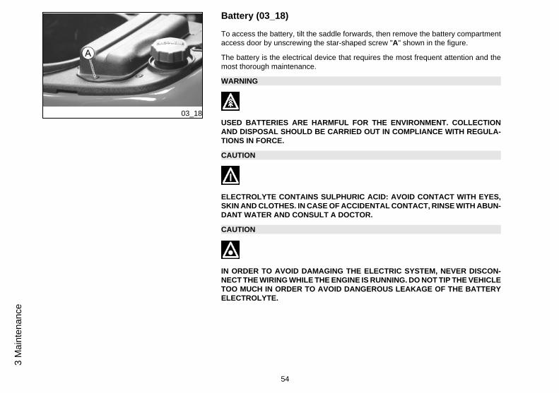
Battery (03_18)
To access the battery, tilt the saddle forwards, then remove the battery compartmentaccess door by unscrewing the star-shaped screw "A" shown in the figure.
The battery is the electrical device that requires the most frequent attention and themost thorough maintenance.
WARNING
USED BATTERIES ARE HARMFUL FOR THE ENVIRONMENT. COLLECTIONAND DISPOSAL SHOULD BE CARRIED OUT IN COMPLIANCE WITH REGULA-TIONS IN FORCE.
CAUTION
ELECTROLYTE CONTAINS SULPHURIC ACID: AVOID CONTACT WITH EYES,SKIN AND CLOTHES. IN CASE OF ACCIDENTAL CONTACT, RINSE WITH ABUN-DANT WATER AND CONSULT A DOCTOR.
CAUTION
IN ORDER TO AVOID DAMAGING THE ELECTRIC SYSTEM, NEVER DISCON-NECT THE WIRING WHILE THE ENGINE IS RUNNING. DO NOT TIP THE VEHICLETOO MUCH IN ORDER TO AVOID DANGEROUS LEAKAGE OF THE BATTERYELECTROLYTE.
54
3 M
aint
enan
ce
03_19
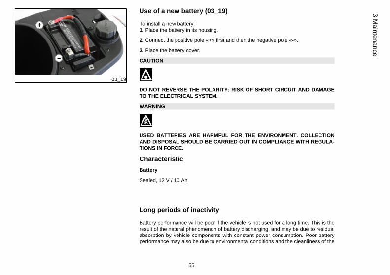
Use of a new battery (03_19)
To install a new battery:1. Place the battery in its housing.
2. Connect the positive pole «+» first and then the negative pole «-».
3. Place the battery cover.
CAUTION
DO NOT REVERSE THE POLARITY: RISK OF SHORT CIRCUIT AND DAMAGETO THE ELECTRICAL SYSTEM.
WARNING
USED BATTERIES ARE HARMFUL FOR THE ENVIRONMENT. COLLECTIONAND DISPOSAL SHOULD BE CARRIED OUT IN COMPLIANCE WITH REGULA-TIONS IN FORCE.
CharacteristicBattery
Sealed, 12 V / 10 Ah
Long periods of inactivity
Battery performance will be poor if the vehicle is not used for a long time. This is theresult of the natural phenomenon of battery discharging, and may be due to residualabsorption by vehicle components with constant power consumption. Poor batteryperformance may also be due to environmental conditions and the cleanliness of the
55
3 Maintenance
poles. In order to avoid difficult starts and/or irreversible damage to the battery, followany of these steps:
- At least once a month start the engine and run it slightly above idle speed for 10-15minutes. This keeps all the engine components, as well as the battery, in good workingorder.
- Take your vehicle to a garage (as indicated in the «Vehicle not used for extendedperiods» section) to have the battery removed. Have the battery cleaned, chargedfully and stored in a dry, ventilated place. Recharge at least once every twomonths.
N.B.
THE BATTERY MUST BE CHARGED WITH A CURRENT EQUAL TO 1/10 OF THERATED CAPACITY OF THE BATTERY AND FOR NOT LONGER THAN 10 HOURS.CONTACT AN AUTHORISED SERVICE CENTRE TO CARRY OUT THIS OPERA-TION SAFELY. WHEN REFITTING THE BATTERY MAKE SURE THE LEADS ARECORRECTLY CONNECTED TO THE TERMINALS.
WARNING
DO NOT DISCONNECT THE BATTERY CABLES WITH THE ENGINE RUNNING,THIS CAN CAUSE IRREPARABLE DAMAGE TO THE VEHICLE'S ELECTRONICCONTROL UNIT.
WARNING
USED BATTERIES ARE HARMFUL FOR THE ENVIRONMENT. COLLECTIONAND DISPOSAL SHOULD BE CARRIED OUT IN COMPLIANCE WITH REGULA-TIONS IN FORCE.
56
3 M
aint
enan
ce
03_20
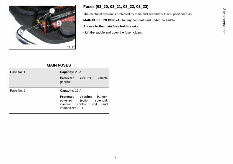
Fuses (03_20, 03_21, 03_22, 03_23)
The electrical system is protected by main and secondary fuses, positioned as:
MAIN FUSE HOLDER «A» battery compartment under the saddle
Access to the main fuse holders «A»:
- Lift the saddle and open the fuse holders.
MAIN FUSESFuse No. 1 Capacity: 20 A
Protected circuits: vehiclegeneral
Fuse No. 2 Capacity: 15 A
Protected circuits: battery-powered injection solenoid,injection control unit andimmobilizer LED.
57
3 Maintenance
03_21
03_22
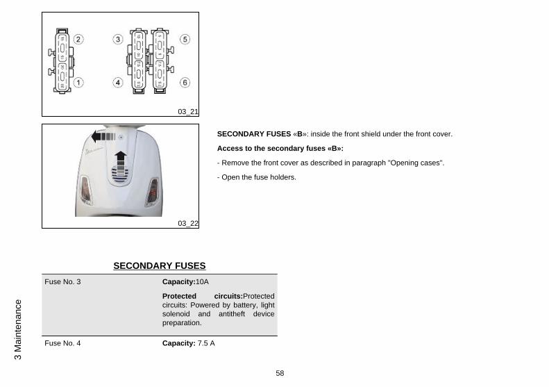
SECONDARY FUSES «B»: inside the front shield under the front cover.
Access to the secondary fuses «B»:
- Remove the front cover as described in paragraph "Opening cases".
- Open the fuse holders.
SECONDARY FUSESFuse No. 3 Capacity:10A
Protected circuits:Protectedcircuits: Powered by battery, lightsolenoid and antitheft devicepreparation.
Fuse No. 4 Capacity: 7.5 A
58
3 M
aint
enan
ce
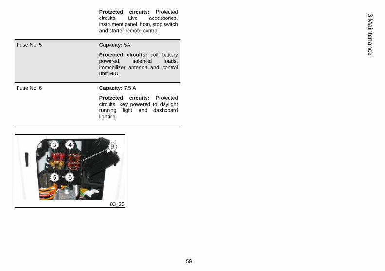
Protected circuits: Protectedcircuits: Live accessories,instrument panel, horn, stop switchand starter remote control.
Fuse No. 5 Capacity: 5A
Protected circuits: coil batterypowered, solenoid loads,immobilizer antenna and controlunit MIU.
Fuse No. 6 Capacity: 7.5 A
Protected circuits: Protectedcircuits: key powered to daylightrunning light and dashboardlighting.
03_23
59
3 Maintenance
CAUTION
BEFORE REPLACING THE FUSE IT IS NECESSARY TO FIND AND SOLVE THEFAILURE THAT CAUSED IT TO BLOW.
DO NOT REPLACE THE FUSE WITH ANY ALTERNATIVE FORM OF CONDUC-TOR.
CAUTION
IN ORDER TO AVOID DAMAGING THE ELECTRIC SYSTEM, NEVER DISCON-NECT THE WIRING WHILE THE ENGINE IS RUNNING. DO NOT TIP THE VEHICLETOO MUCH IN ORDER TO AVOID DANGEROUS LEAKAGE OF THE BATTERYELECTROLYTE.
CAUTION
MODIFICATIONS OR REPAIRS TO THE ELECTRICAL SYSTEM, PERFORMEDINCORRECTLY OR WITHOUT STRICT ATTENTION TO THE TECHNICAL SPEC-IFICATIONS OF THE SYSTEM CAN CAUSE MALFUNCTIONING AND RISK OFFIRE.
CAUTION
PERFORM THE OPERATIONS CAREFULLY.DO NOT DAMAGE THE TONGUES OR THEIR SEATS. HANDLE THE PAINTEDAND PLASTIC COMPONENTS CAREFULLY. DO NOT SCRATCH OR DAMAGETHEM.
60
3 M
aint
enan
ce

BULBSHigh/low beam light bulb Type: Halogen (H4)
Power: 12V - 55/60W
Quantity: 1
Front daylight running light bulbs Type: Incandescent
Power:12V - 5W
Quantity: 1
Stop light/rear daylight runninglight bulb
Type: Incandescent
Power:12V-5W/16W
Quantity: 1
License plate bulb Type: Incandescent
Power: 12V - 5W
Quantity: 1
Front turn indicator light bulb Type: Incandescent, BAU 15S,Amber
Power: 12V - 10W
Quantity: 1 RHS + 1 LHS
Rear turn indicator light bulb Type: Incandescent, BAU 15S,Amber
61
3 Maintenance
Power: 12V - 10W
Quantity: 1 RHS + 1 LHS
Instrument panel bulb Type: Incandescent
Power: 12V - 2W
Quantity: 3
03_24
03_25
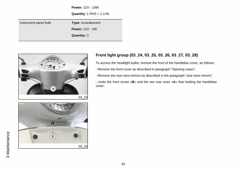
Front light group (03_24, 03_25, 03_26, 03_27, 03_28)
To access the headlight bulbs, remove the front of the handlebar cover, as follows:
- Remove the front cover as described in paragraph "Opening cases".
- Remove the rear-view mirrors as described in the paragraph "rear-view mirrors".
- Undo the front screw «B» and the two rear ones «A» that holding the handlebarcover.
62
3 M
aint
enan
ce
03_26
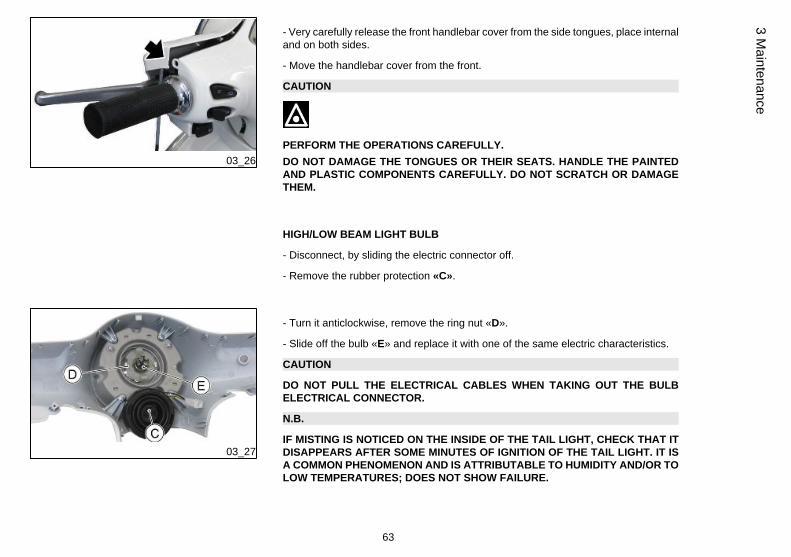
- Very carefully release the front handlebar cover from the side tongues, place internaland on both sides.
- Move the handlebar cover from the front.
CAUTION
PERFORM THE OPERATIONS CAREFULLY.DO NOT DAMAGE THE TONGUES OR THEIR SEATS. HANDLE THE PAINTEDAND PLASTIC COMPONENTS CAREFULLY. DO NOT SCRATCH OR DAMAGETHEM.
HIGH/LOW BEAM LIGHT BULB
- Disconnect, by sliding the electric connector off.
- Remove the rubber protection «C».
03_27
- Turn it anticlockwise, remove the ring nut «D».
- Slide off the bulb «E» and replace it with one of the same electric characteristics.
CAUTION
DO NOT PULL THE ELECTRICAL CABLES WHEN TAKING OUT THE BULBELECTRICAL CONNECTOR.
N.B.
IF MISTING IS NOTICED ON THE INSIDE OF THE TAIL LIGHT, CHECK THAT ITDISAPPEARS AFTER SOME MINUTES OF IGNITION OF THE TAIL LIGHT. IT ISA COMMON PHENOMENON AND IS ATTRIBUTABLE TO HUMIDITY AND/OR TOLOW TEMPERATURES; DOES NOT SHOW FAILURE.
63
3 Maintenance
THE PRESENCE OF DROPS OF WATER, ON THE OTHER HAND, COULD INDI-CATE THAT WATER IS INFILTRATING. CONTACT AN AUTHORISED SERVICECENTRE.
03_28
DAYLIGHT RUNNING LIGHT BULB
- Slide off the bulb «F»from the seat, paying attention to the electrical connections.
- Slide off the bulb from the bulb holder and replace it.
CAUTION
DO NOT PULL THE ELECTRICAL CABLES WHEN TAKING OUT THE BULBHOLDER.
03_29
Headlight adjustment (03_29, 03_30)
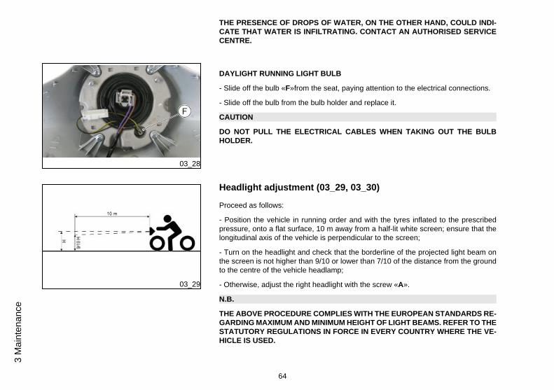
Proceed as follows:
- Position the vehicle in running order and with the tyres inflated to the prescribedpressure, onto a flat surface, 10 m away from a half-lit white screen; ensure that thelongitudinal axis of the vehicle is perpendicular to the screen;
- Turn on the headlight and check that the borderline of the projected light beam onthe screen is not higher than 9/10 or lower than 7/10 of the distance from the groundto the centre of the vehicle headlamp;
- Otherwise, adjust the right headlight with the screw «A».
N.B.
THE ABOVE PROCEDURE COMPLIES WITH THE EUROPEAN STANDARDS RE-GARDING MAXIMUM AND MINIMUM HEIGHT OF LIGHT BEAMS. REFER TO THESTATUTORY REGULATIONS IN FORCE IN EVERY COUNTRY WHERE THE VE-HICLE IS USED.
64
3 M
aint
enan
ce
03_30
03_31
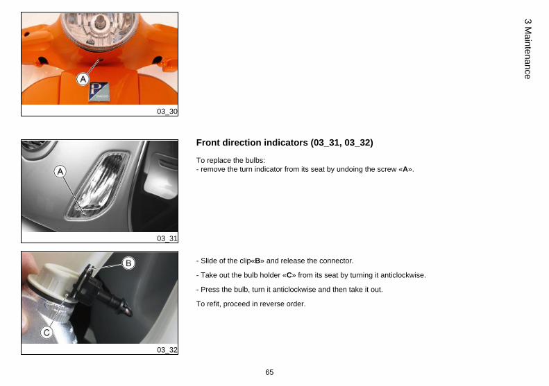
Front direction indicators (03_31, 03_32)
To replace the bulbs:- remove the turn indicator from its seat by undoing the screw «A».
03_32
- Slide of the clip«B» and release the connector.
- Take out the bulb holder «C» from its seat by turning it anticlockwise.
- Press the bulb, turn it anticlockwise and then take it out.
To refit, proceed in reverse order.
65
3 Maintenance
03_33
03_34
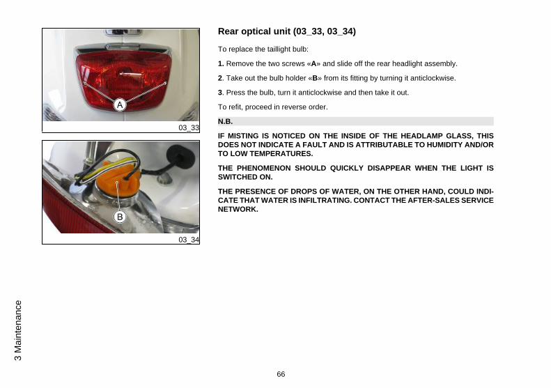
Rear optical unit (03_33, 03_34)
To replace the taillight bulb:
1. Remove the two screws «A» and slide off the rear headlight assembly.
2. Take out the bulb holder «B» from its fitting by turning it anticlockwise.
3. Press the bulb, turn it anticlockwise and then take it out.
To refit, proceed in reverse order.
N.B.
IF MISTING IS NOTICED ON THE INSIDE OF THE HEADLAMP GLASS, THISDOES NOT INDICATE A FAULT AND IS ATTRIBUTABLE TO HUMIDITY AND/ORTO LOW TEMPERATURES.
THE PHENOMENON SHOULD QUICKLY DISAPPEAR WHEN THE LIGHT ISSWITCHED ON.
THE PRESENCE OF DROPS OF WATER, ON THE OTHER HAND, COULD INDI-CATE THAT WATER IS INFILTRATING. CONTACT THE AFTER-SALES SERVICENETWORK.
66
3 M
aint
enan
ce
03_35
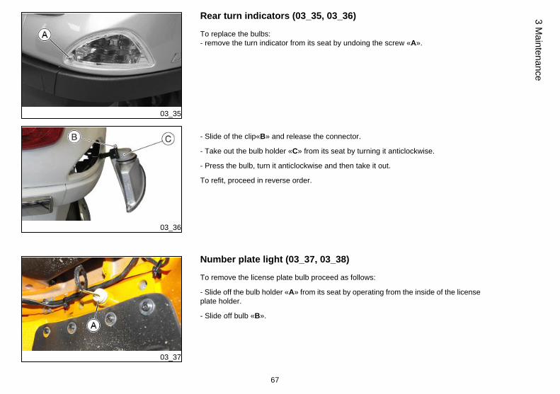
Rear turn indicators (03_35, 03_36)
To replace the bulbs:- remove the turn indicator from its seat by undoing the screw «A».
03_36
- Slide of the clip«B» and release the connector.
- Take out the bulb holder «C» from its seat by turning it anticlockwise.
- Press the bulb, turn it anticlockwise and then take it out.
To refit, proceed in reverse order.
03_37
Number plate light (03_37, 03_38)
To remove the license plate bulb proceed as follows:
- Slide off the bulb holder «A» from its seat by operating from the inside of the licenseplate holder.
- Slide off bulb «B».
67
3 Maintenance
03_38
CAUTION
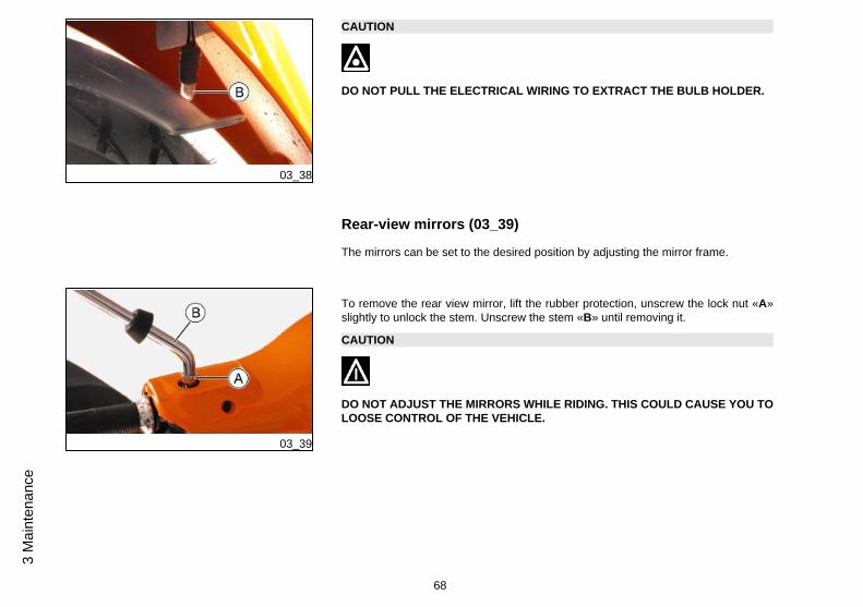
DO NOT PULL THE ELECTRICAL WIRING TO EXTRACT THE BULB HOLDER.
Rear-view mirrors (03_39)
The mirrors can be set to the desired position by adjusting the mirror frame.
03_39
To remove the rear view mirror, lift the rubber protection, unscrew the lock nut «A»slightly to unlock the stem. Unscrew the stem «B» until removing it.
CAUTION
DO NOT ADJUST THE MIRRORS WHILE RIDING. THIS COULD CAUSE YOU TOLOOSE CONTROL OF THE VEHICLE.
68
3 M
aint
enan
ce
03_40
Front disc brake (03_40)
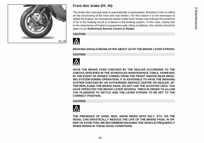
The brake disc and pad wear is automatically compensated, therefore it has no effecton the functioning of the front and rear brakes. For this reason it is not necessary toadjust the brakes. An excessively elastic brake lever stroke may indicate the presenceof air in the braking circuit or a failure in the braking system. In this case, mainly dueto the importance of brakes to guarantee safe riding conditions, the vehicle should betaken to an Authorised Service Centre or Dealer.
CAUTION
BRAKING SHOULD BEGIN AFTER ABOUT 1/3 OF THE BRAKE LEVER STROKE.
CAUTION
HAVE THE BRAKE PADS CHECKED BY THE DEALER ACCORDING TO THECHECKS SPECIFIED IN THE SCHEDULED MAINTENANCE TABLE. HOWEVER,IN THE EVENT OF NOISES COMING FROM THE FRONT AND/OR REAR BRAK-ING SYSTEM DURING OPERATION, IT IS ADVISABLE TO HAVE THE BRAKINGSYSTEM CHECKED BY AN AUTHORISED SERVICE CENTRE OR DEALER. AF-TER REPLACING THE BRAKE PADS, DO NOT USE THE SCOOTER UNTIL YOUHAVE OPERATED THE BRAKE LEVER SEVERAL TIMES IN ORDER TO ALLOWTHE PLUNGERS TO SETTLE AND THE LEVER STROKE TO BE SET TO THECORRECT POSITION.
CAUTION
THE PRESENCE OF SAND, MUD, SNOW MIXED WITH SALT, ETC. ON THEROAD, CAN DRASTICALLY REDUCE THE LIFE OF THE BRAKE PADS. IN OR-DER TO AVOID THIS, WE RECOMMEND WASHING THE VEHICLE FREQUENTLYWHEN RIDING IN THESE ROAD CONDITIONS.
69
3 Maintenance
03_41
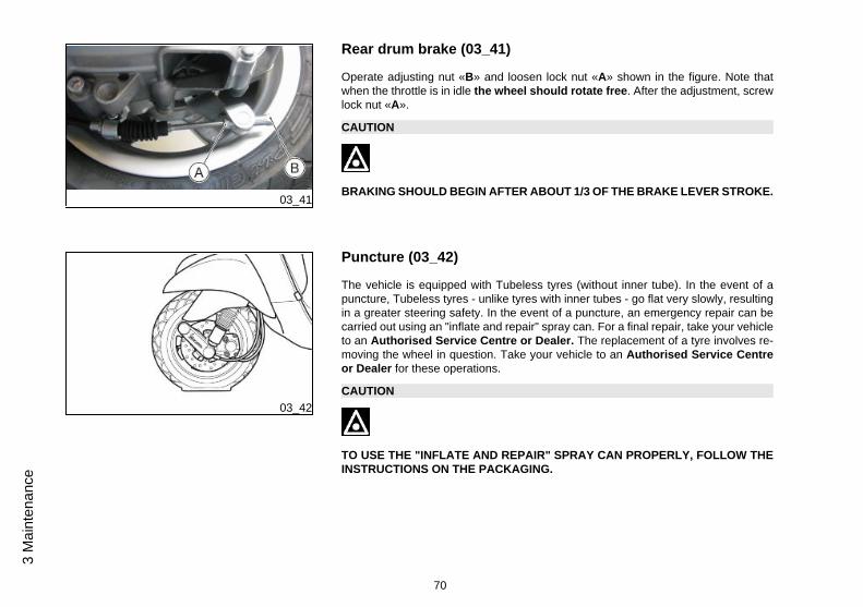
Rear drum brake (03_41)
Operate adjusting nut «B» and loosen lock nut «A» shown in the figure. Note thatwhen the throttle is in idle the wheel should rotate free. After the adjustment, screwlock nut «A».
CAUTION
BRAKING SHOULD BEGIN AFTER ABOUT 1/3 OF THE BRAKE LEVER STROKE.
03_42
Puncture (03_42)
The vehicle is equipped with Tubeless tyres (without inner tube). In the event of apuncture, Tubeless tyres - unlike tyres with inner tubes - go flat very slowly, resultingin a greater steering safety. In the event of a puncture, an emergency repair can becarried out using an "inflate and repair" spray can. For a final repair, take your vehicleto an Authorised Service Centre or Dealer. The replacement of a tyre involves re-moving the wheel in question. Take your vehicle to an Authorised Service Centreor Dealer for these operations.
CAUTION
TO USE THE "INFLATE AND REPAIR" SPRAY CAN PROPERLY, FOLLOW THEINSTRUCTIONS ON THE PACKAGING.
70
3 M
aint
enan
ce
03_43
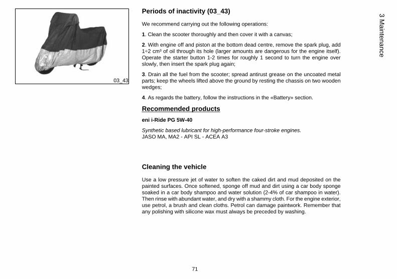
Periods of inactivity (03_43)
We recommend carrying out the following operations:
1. Clean the scooter thoroughly and then cover it with a canvas;
2. With engine off and piston at the bottom dead centre, remove the spark plug, add1÷2 cm³ of oil through its hole (larger amounts are dangerous for the engine itself).Operate the starter button 1-2 times for roughly 1 second to turn the engine overslowly, then insert the spark plug again;
3. Drain all the fuel from the scooter; spread antirust grease on the uncoated metalparts; keep the wheels lifted above the ground by resting the chassis on two woodenwedges;
4. As regards the battery, follow the instructions in the «Battery» section.
Recommended productseni i-Ride PG 5W-40
Synthetic based lubricant for high-performance four-stroke engines.JASO MA, MA2 - API SL - ACEA A3
Cleaning the vehicle
Use a low pressure jet of water to soften the caked dirt and mud deposited on thepainted surfaces. Once softened, sponge off mud and dirt using a car body spongesoaked in a car body shampoo and water solution (2-4% of car shampoo in water).Then rinse with abundant water, and dry with a shammy cloth. For the engine exterior,use petrol, a brush and clean cloths. Petrol can damage paintwork. Remember thatany polishing with silicone wax must always be preceded by washing.
71
3 Maintenance
CAUTION
DETERGENTS CAN POLLUTE WATER. THE VEHICLE MUST BE WASHED AT AWASH STATION EQUIPPED WITH A SPECIAL WATER PURIFICATION SYSTEM.
CAUTION
DO NOT USE A HIGH-PRESSURE WATER JET MACHINE TO CLEAN THE EN-GINE AND/OR VEHICLE; HOWEVER, IF NO OTHER MEANS ARE AVAILABLE, ITIS THEN NECESSARY TO:• ONLY USE A FANLIKE SPRAY JET.
• DO NOT PLACE THE NOZZLE CLOSER THAN 60 CM.
• DO NOT USE WATER AT TEMPERATURES OVER 40ºC.
• DO NOT USE HIGH-PRESSURE WATER JETS.
• DO NOT STEAM WASH.
• DO NOT AIM THE JET AT: THE ENGINE, THE WIRING, THE COOLING SLITSON THE TRANSMISSION OR SCROLL COVERS.
CAUTION
NEVER WASH THE SCOOTER IN DIRECT SUNLIGHT, ESPECIALLY IN SUMMERWHEN THE BODYWORK IS STILL HOT AS THE SHAMPOO COULD DAMAGETHE PAINTWORK IF IT DRIES BEFORE BEING RINSED OFF. NEVER USECLOTHS SOAKED IN ALCOHOL, PETROL, DIESEL OIL OR KEROSENE FORCLEANING THE PAINTED OR PLASTIC SURFACES, IN ORDER NOT TO DAM-AGE THE LUSTRE FINISH OR ALTER THEIR MECHANICAL PROPERTIES. US-ING SILICONE-BASED WAX CAN DAMAGE THE PAINTED SURFACES, DE-PENDING ON THE VEHICLE COLOUR (SATIN COLOURS). FOR FURTHER
72
3 M
aint
enan
ce
INFORMATION ON THIS MATTER, CONTACT AN AUTHORISED SERVICE CEN-TRE.
WARNING
CLEAN YOUR SCOOTER FREQUENTLY SO AS TO AVOID POSSIBLE DIRT ORMUD DEPOSITS THAT COULD CAUSE MALFUNCTIONING IN THE THROTTLEGRIP TRANSMISSION AND/OR OTHER COMPONENTS.
Troubleshooting
STARTING FAILUREFuse blown Replace the blown fuse and have
the vehicle checked by anAuthorised Service Centre.
STARTING DIFFICULTIES (SEE «STARTERPROBLEMS» SECTION)
Lack of fuel in tank. Refuelling
Injection system fault Contact an Authorised ServiceCentre
73
3 Maintenance
Fuel pump fault Contact an Authorised ServiceCentre
Flat battery Recharge the battery.
* IMPORTANT: DO NOT USE THE SCOOTER TO THE COMPLETEEXHAUSTION OF FUEL; SHOULD THIS OCCUR, DO NOTATTEMPT TO START THE ENGINE. TURN THE IGNITION KEY TO«OFF» AND TOP-UP THE FUEL TANK AS SOON AS POSSIBLE.FAILURE TO FOLLOW THESE GUIDELINES COULD DAMAGE THEFUEL PUMP AND/OR THE CATALYTIC CONVERTER.
IGNITION PROBLEMSFaulty spark plug Contact an Authorised Service
Centre.
Faulty ignition / injection controlunit. Due to the presence of highvoltage, this check should only becarried out by an expert.
Contact an Authorised ServiceCentre
LACK OF COMPRESSIONLoose spark plug. Screw in the spark plug tightly
Cylinder head loose, piston gasrings worn.
Contact an Authorised ServiceCentre.
Valve stuck Contact an Authorised ServiceCentre.
74
3 M
aint
enan
ce
HIGH CONSUMPTION AND LOW PERFORMANCEClogged or dirty air filter Try to blow out with compressed
air, otherwise replace the filter
INSUFFICIENT BRAKINGGreasy disc. Worn pads. Faultybraking system. Presence of air inthe front and rear brake circuit.
Contact an Authorised ServiceCentre.
INEFFICIENT SUSPENSIONShock absorber fault, oil leak, endbuffers damaged; shock absorberpreloading incorrectly set
Contact an Authorised ServiceCentre.
AUTOMATIC TRANSMISSION PROBLEMSCVT rollers and/or drive beltdamaged
Contact an Authorised ServiceCentre.
75
3 Maintenance

76
3 M
aint
enan
ce
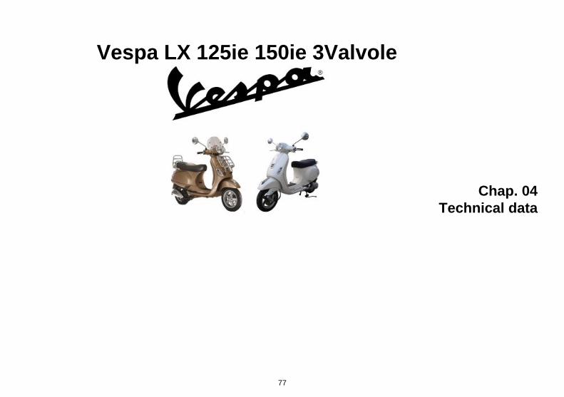
Vespa LX 125ie 150ie 3Valvole
Chap. 04Technical data
77
Data (04_01)
04_01
78
4 Te
chni
cal d
ata
VEHICLE TECHNICAL DATAFrame Stamped plate body with welded
structural reinforcements.
Front suspension Single arm with helical spring andsingle double-acting hydraulicshock absorber.
rear suspension Double-acting shock absorber,adjustable to four positions atpreloading.
Front brake Ø 200-mm disc brake withhydraulic control activated byhandlebar right-side lever.
Rear brake Ø 110-mm drum brake withmechanical control activated byhandlebar left-side lever.
Wheel rim type Light alloy wheel rims.
Front wheel rim 11'' x 2.50
Rear wheel rim 10'' x 3.00
Front tyre Tubeless, 110/70 - 11'' 45L
Rear tyre Tubeless, 120/70 - 10'' 54L
Front tyre pressure 1.6 bar
Rear tyre pressure (withpassenger)
2.0 bar (2.3 bar)
Kerb weight 114 kg
Maximum weight allowed 300 kg
Battery Sealed, 12 V / 10 Ah
79
4 Technical data
125 CM³ ENGINE SPECIFICATIONSType Single-cylinder, 4-stroke
Engine capacity 124 cm³
Bore x stroke 52.0 x 58.6 mm
Max. power 8.5 kW at 8,250 rpm
MAX. torque 10.7 Nm at 6,500 rpm
Compression ratio (10.5±0.5):1
Idle speed (1,750±100) rpm
Valve clearance intake: 0.08 mmexhaust: 0.08 mm
Timing system 3 valves (2 intake, 1 drainage).single overhead camshaft chain-driven.
Transmission CVT expandable pulley variatorwith torque server, V-belt, self-ventilating dry automaticcentrifugal clutch and transmissionhousing with forced-circulation aircooling.
Final reduction gear Gear reduction unit in oil bath.
Lubrication Engine lubrication with lobe pump(inside crankcase), chain-driven,with double filter: mesh and paper.
Cooling Forced-air circulation cooling.
Starter Electric starter
80
4 Te
chni
cal d
ata
Ignition Electronic inductive dischargeignition, with variable advance andseparate HV coil.
Ignition advance Three-dimensional map managedby control unit
Spark plug (125cm³) NGK CR8EB
Electrode gap 0.7 to 0.8 mm
Fuel system Electronic injection with Ø 28 mmthrottle body, single injector
Fuel Unleaded petrol (95 RON)
Exhaust silencer Absorption-type exhaust mufflerwith catalytic converter.
Emissions compliance EURO 3
150 CM³ ENGINE SPECIFICATIONSType Single-cylinder, 4-stroke
Cubic capacity 155 cm³
Bore x stroke 58.0 x 58.6 mm
Max. power 8.5 kW at 8,250 rpm
MAX. torque 12.8 Nm at 6,250 rpm
Compression ratio (10.5±0.5):1
Idle speed (1,750±100) rpm
Valve clearance intake: 0.08 mm
81
4 Technical data
exhaust: 0.08 mm
Timing system 3 valves (2 intake, 1 drainage).single overhead camshaft chain-driven.
Transmission CVT expandable pulley variatorwith torque server, V-belt, self-ventilating dry automaticcentrifugal clutch and transmissionhousing with forced-circulation aircooling.
Final reduction gear Gear reduction unit in oil bath.
Lubrication Engine lubrication with lobe pump(inside crankcase), chain-driven,with double filter: mesh and paper.
Cooling Forced-air circulation cooling.
Starter Electric starter
Ignition Electronic inductive dischargeignition, with variable advance andseparate HV coil.
Ignition advance Three-dimensional map managedby control unit
Spark plug (150cm³) NGK CR8EB
Electrode gap 0.7 to 0.8 mm
Fuel system Electronic injection with Ø 28 mmthrottle body, single injector
Fuel Unleaded petrol (95 RON)
Exhaust silencer Absorption-type exhaust mufflerwith catalytic converter.
82
4 Te
chni
cal d
ata
Emissions compliance EURO 3
CAPACITYEngine oil 1220 cc (of which 120 cc in the
filtering cartridge)
Hub oil 200 cm³
Fuel tank capacity (8.2±0.5) l
04_02
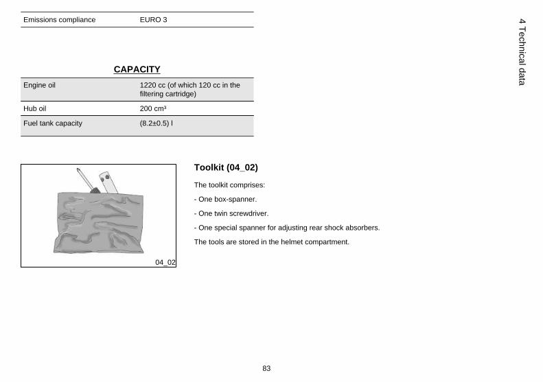
Toolkit (04_02)
The toolkit comprises:
- One box-spanner.
- One twin screwdriver.
- One special spanner for adjusting rear shock absorbers.
The tools are stored in the helmet compartment.
83
4 Technical data

84
4 Te
chni
cal d
ata

Vespa LX 125ie 150ie 3Valvole
Chap. 05Spare parts and
accessories
85
05_01
Warnings (05_01)
WARNING
IT IS RECOMMENDED THAT "ORIGINAL PIAGGIO SPARE PARTS" BE USED,AS THESE ARE THE ONLY ONES OFFERING YOU THE SAME QUALITY AS-SURANCE AS THOSE INITIALLY FITTED ON THE VEHICLE.
IT SHOULD BE REMEMBERED THAT USING NON-ORIGINAL SPARE PARTSCAUSES YOUR WARRANTY RIGHTS TO EXPIRE.
WARNING
PIAGGIO MARKETS ITS OWN LINE OF ACCESSORIES THAT ARE RECOG-NISED AND GUARANTEED FOR USE. IT IS THEREFORE ESSENTIAL TO CON-TACT AN AUTHORISED DEALER OR SERVICE CENTRE IN ORDER TO CHOOSEAND FIT ACCESSORIES CORRECTLY. THE USE OF NON-ORIGINAL ACCES-SORIES MAY AFFECT THE STABILITY AND OPERATION OF YOUR VEHICLEAND REDUCE SAFETY LEVELS WITH POTENTIAL RISKS FOR THE RIDER.
86
5 Sp
are
parts
and
acc
esso
ries

Vespa LX 125ie 150ie 3Valvole
Chap. 06Scheduled
maintenance
87
06_01
Scheduled servicing table (06_01)
Adequate maintenance is fundamental to ensuring long-lasting, optimum operationand performance of your vehicle.
To this end, a series of checks and maintenance operations (at the owner's expense)have been suggested, which are included in the summary table on the following page.Any minor faults should be reported without delay to an Authorised Service Centreor Dealer without waiting until the next scheduled service to solve it.
It is indispensable to have your vehicle serviced to the prescribed intervals of time,even if you have not reached the predicted mileage. Punctual vehicle servicing isnecessary for the correct use of the guarantee. For any further information concerningWarranty procedures and 'Scheduled Maintenance', please refer to the 'WarrantyBooklet'.
SCHEDULED MAINTENANCE TABLEkm x 1,000 1 5 10 15 20 25 30
Safety fasteners I I I I
Spark plug I R I R I R
Cartridge air filter C C R
Centre stand bracket L L L L L L
Driving belt (125cc) I R I
Driving belt (150cc) R R R
Throttle control A A A A
Roller housing I I I
Air filter I I I
Engine oil filter R R R R
88
6 Sc
hedu
led
mai
nten
ance
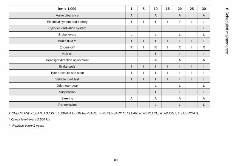
km x 1,000 1 5 10 15 20 25 30
Valve clearance A A A A
Electrical system and battery I I I I I I I
Cylinder ventilation system I
Brake levers L L L L
Brake fluid ** I I I I I I I
Engine oil* R I R I R I R
Hub oil I I I
Headlight direction adjustment A A A
Brake pads I I I I I I I
Tyre pressure and wear I I I I I I I
Vehicle road test I I I I I I I
Odometer gear L L L
Suspension I I I
Steering A A A A
Transmission L L L
I: CHECK AND CLEAN, ADJUST, LUBRICATE OR REPLACE, IF NECESSARY C: CLEAN; R: REPLACE; A: ADJUST; L: LUBRICATE
* Check level every 2,500 km
** Replace every 2 years
89
6 Scheduled maintenance
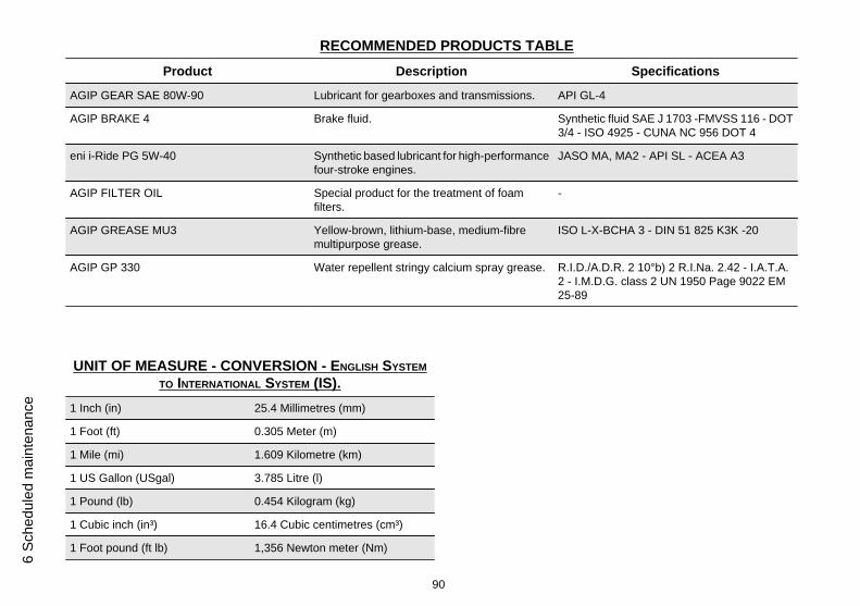
RECOMMENDED PRODUCTS TABLEProduct Description Specifications
AGIP GEAR SAE 80W-90 Lubricant for gearboxes and transmissions. API GL-4
AGIP BRAKE 4 Brake fluid. Synthetic fluid SAE J 1703 -FMVSS 116 - DOT3/4 - ISO 4925 - CUNA NC 956 DOT 4
eni i-Ride PG 5W-40 Synthetic based lubricant for high-performancefour-stroke engines.
JASO MA, MA2 - API SL - ACEA A3
AGIP FILTER OIL Special product for the treatment of foamfilters.
-
AGIP GREASE MU3 Yellow-brown, lithium-base, medium-fibremultipurpose grease.
ISO L-X-BCHA 3 - DIN 51 825 K3K -20
AGIP GP 330 Water repellent stringy calcium spray grease. R.I.D./A.D.R. 2 10°b) 2 R.I.Na. 2.42 - I.A.T.A.2 - I.M.D.G. class 2 UN 1950 Page 9022 EM25-89
UNIT OF MEASURE - CONVERSION - ENGLISH SYSTEMTO INTERNATIONAL SYSTEM (IS).
1 Inch (in) 25.4 Millimetres (mm)
1 Foot (ft) 0.305 Meter (m)
1 Mile (mi) 1.609 Kilometre (km)
1 US Gallon (USgal) 3.785 Litre (l)
1 Pound (lb) 0.454 Kilogram (kg)
1 Cubic inch (in³) 16.4 Cubic centimetres (cm³)
1 Foot pound (ft lb) 1,356 Newton meter (Nm)
90
6 Sc
hedu
led
mai
nten
ance
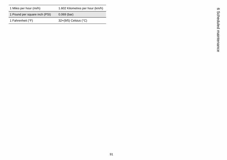
1 Miles per hour (mi/h) 1.602 Kilometres per hour (km/h)
1 Pound per square inch (PSI) 0.069 (bar)
1 Fahrenheit (°F) 32+(9/5) Celsius (°C)
91
6 Scheduled maintenance

92
6 Sc
hedu
led
mai
nten
ance
TABLE OF CONTENTS
AAir filter: 50
BBattery: 54, 55Brake: 51, 69, 70
CChecks: 26Clock: 11
DDisc brake: 69
EEngine oil: 42–44
FFuel: 19Fuses: 57
HHeadlight: 64Horn: 14Hub oil: 46
IIdentification: 21Immobilizer: 15, 17Instrument panel: 9
KKey switch: 12Keys: 16
LLight switch: 14
MMaintenance: 41, 87Mirrors: 68
PPuncture: 70
RRefuelling: 26
SSaddle: 20Scheduled maintenance: 87Shock absorbers: 28Spark plug: 49Stand: 36
Start-up: 15Switch: 12, 14
TTank: 19Technical Data: 77Toolkit: 83Top box: 23Transmission: 36Turn indicators: 67Tyre pressure: 27Tyres: 48
VVehicle: 7, 71
93

The descriptions and images in this publication are given for illustrative purposes only and are not binding. While the basic characteristics as described and illustrated in this booklet remain unchanged,Piaggio & C. S.p.A. reserves the right, at any time and without being required to update this publication beforehand, to make any changes to components, parts or accessories, which it considers
necessary to improve the product or which are required for manufacturing or construction reasons.
Not all versions/models shown in this publication are available in all countries. The availability of each model should be checked at the official PIAGGIO sales network.
© Copyright 2012 - Piaggio & C. S.p.A. All rights reserved. Reproduction of this publication in whole or in part is prohibited.
Piaggio & C. S.p.A. Viale Rinaldo Piaggio, 25 - 56025 PONTEDERA (PI), Italy
www.piaggio.com