very small duty cycles for pulsed time domain transistor
TRANSCRIPT

EUROPEAN MICROWAVE ASSOCIATION
Very small duty cycles for pulsed time domain transistorcharacterization
Fabien De Groote1, Olivier Jardel2, Tibault Reveyrand2,Jean-Pierre Teyssier1, 2 and Raymond Quere2
Abstract – This paper deals with an innovative approach forpulsed measurements, particularly suited for RF time domaintransistor characterization. This approach avoids the loss of dy-namic range induced by classical methods when the duty cy-cle decreases. The application of this principle with a LSNA isshown; an additional board has been added into the LSNA tomanage all the necessary triggers and clocks. Results are shownwith a HEMT AlGaN/GaN, duty cycles up to 0.0001 are demon-strated with 1 μs pulse durations.Index Terms – Duty cycle, Dynamic range, LSNA, Pulsed mea-surements, RF transistor, Time domain measurements.
I. IntroductionRF designers need to have complete information about op-erating conditions of their transistors, particularly whenthey are used in the saturation region. They can today sim-ulate time domain slopes in their RF software, and partic-ularly load lines, to preview the behavior of the transistors.So, there is an interest in comparing simulations againstmeasurements. It means to be able to measure directly ab-solute amplitudes and phases relations for a wide num-ber of the harmonic frequencies at both accesses of a mi-crowave transistor [1]. For high harmonic range, the poweris very small compared to the power at the fundamentalfrequency, so keeping the dynamic range of the measure-ment system is a challenge. Measurement setups which arebased on a MTA or a LSNA [2,3] can acquire this type ofinformation, but today the dynamic range of these systemsis lower than up-to-date VNAs.Moreover, working on pulsed conditions is really interest-ing for RF transistor characterization [4,5]. This excitationmode can be used to identify thermal and traps effects, orto explore the transistor limits [6,7]. So it is a key point tobe able to perform time domain measurements in variouspulsed modes, e.g. for a wide choice of duty cycles andpulse widths.This paper presents results of the time domain approachfor measuring RF slopes in pulsed mode. A wide domainof duty cycles is explored, up to 0.0001, while keepingall the measurement system dynamic range, even for shortpulse widths. This principle has been applied with a LSNAmeasuring an AlGaN/GaN HEMT.
II. Different measurement methods underpulsed conditionsThere are two main different approaches for pulsed modemeasurements: the “frequency domain” approach (FDA)and the “time domain” one (TDA).
A) Frequency domain approach
The FDA is very classical and used in a lot of microwaveslabs. Two methods are used: measurement of one filteredfrequency and wideband measurements [8,9].Measuring data at only one center frequency implies aninherent dynamic range loss linked to duty cycle. It givesthe well known equation (1), where α is the duty cycle,and �dyn the dynamic range loss.
(1) �dyn = 20 log(α)
Consequently, the noise floor of the measurement systemis strongly degraded with the FDA when α decreases. Up-to-date VNAs have very good noise floors, so they canhandle pulsed measurements at relatively small duty cy-cles.But for time domain measurements, with a LSNA, the fol-lowing example gives the dynamic loss in this configura-tion:
Example: output power (f0) = 20 dBm;Dynamic range (CW) = 60 dB;α = 1 %.
Conclusion: Noise floor (α = 1 %) = 0 dBm
If the power at a harmonic frequency is lower than 0 dBm,it can not be measured by the system in this pulse config-uration, even if in it was possible in CW mode.The second frequency method consists in a wideband mea-surement. The dynamic losses still exist because all thefrequency lines can not be acquired by the receiver. Theselosses are lower than the first frequency method; howeveran important disadvantage is that a minimum pulse widthis required, often several microseconds.But in the context of RF transistor time domain character-ization, pulsed measurements have to be performed withenough dynamic range to acquire amplitude and phase ofa maximum of harmonic frequencies, for a wide range ofduty cycles, and with short pulse widths, typically loweror equal than 1 μs.
Received September 28th, 2007. Revised December 21th, 2007.1Are with Verspecht-Teyssier-DeGroote SAS, IUT GEII 7 rueJules Valles, 19100 Brive, France;E-mail: degroote@brive,unilim.fr;2Are with XLIM, Limoges University, 123 Av. Albert Thomas,87060 Limoges, France.
Proceedings of the European Microwave Association Vol. 4; June 2008; 112–117

F. DE GROOTE, O. JARDEL, T. REVEYRAND, J.-P. TEYSSIER AND R. QUERE
(a) (b) (c)
Fig. 1. (a) ADC sampling result with the TDA. 1 period between two acquisitions. (b) ADC sampling result with the TDS. 100 periodsbetween two acquisitions. (c) ADC sampling result with the TDA. 100 periods between two acquisitions and something wrong.
B) Time domain approach
The principle of the TDA was described in [10,11]. It isbased on a progressive acquisition of all the points of thesignal. Inside every pulse, a defined number of samplesis stored, and put together with the precedent ones. Thisprinciple is like the stroboscope approach, because theADC trigger is lightly shifted compared to the observedfrequency. The computation of all the related frequenciesof the system – ADC sampling, ADC trigger, intermediatefrequency from the LSNA – is a key point, to be sure ofthe phase coherence between the sample groups.This method implies the acquisition time directly dependson the duty cycle but it has in theory no consequence onthe dynamic of the considered system. Another importantpoint is that the TDA needs a common reference for thetrigger of the ADCs and for the RF receiver.
III. Time domain approach integration intoLSNAA) Verification of the time domain approach with theADCs
A preliminary test to evaluate the time domain approach inthe LSNA is to check the dynamic range of the ADCs. Ifall the frequencies computation is well done, no dynamicloss should appear even for very low duty cycles in pulsedmode.An appropriate test is to sample a CW 100 kHz signal withthe ADCs at a sampling frequency at 10 MHz. The ADCsare in pulsed mode, with the TDA, so a trigger at a precisefrequency has to be furnished.Three main points in this kind of integration are to be con-sidered: first the trigger frequency has to be locked to areference frequency, typically a 10 MHz signal; secondthe trigger frequency is obtained by a division of the ADC
sampling frequency; third, the delay between two samplegroups is an integer of the IF period.The quality of TDA can be checked by a long acquisi-tion of the IF signal: the needed acquisition time dependson duty cycle. So a problem in ADCs settings or trig-gers could be found by looking at the measured DiscreteFourier Transform spectrum lines. If the TDA is available,time and frequency measurement results have to be thesame for a wide choice of duty cycles.Three different configurations will be showed:
– 5 samples in each period, delay of one period betweentwo sampling triggers;
– 5 samples in each period, delay of one hundred peri-ods between two sampling triggers.
– 5 samples in each period, 100 periods delay andsomething wrong was introduced in the trigger set-tings: the ADC sampling frequency was divided by10106 instead of 10105 to give the trigger frequency.
The Fig. 1 shows the result in the time and frequency do-mains for each configuration described above.
– Fig. 1a: one period delay;– Fig. 1b: 100 periods delay;– Fig. 1c: something wrong
No phase problem in time slopes appears when the dutycycle decreases; it is confirmed with frequency spectra,where no unexpected line appears.These results are very well suited for microwaves. TheADCs dynamic range becomes independent of the dutycycle choice. It means that a receiver like a LSNA, whichhas a smaller dynamic range than up-to-date VNAs, can beused with the capabilities of the CW mode. Moreover, it iseasy to check the trigger settings computation by lookingat the spectrum lines.
Proceedings of the European Microwave Association 113

VERY SMALL DUTY CYCLES FOR PULSED TIME DOMAIN TRANSISTOR CHARACTERIZATION
B) The “Pulse Controller Board” associated to theLSNA
The measurement setup is based on a LSNA. A dedicateddigital board has been created to generate all the triggerswe need to work in pulsed mode [12]. The principle is touse a very precise frequency synthesizer (called FracN)to drive the acquisition triggers and all the others deviceswhich need a trigger: oscilloscope, RF source, pulse gener-ators. The Fig. 2 shows the main links between the devicesto work in pulsed mode.
Fig. 2. Clocks and triggers management.
IV. Application to RF transistormeasurement
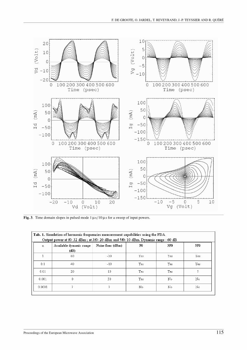
Pulsed LSNA measurements with the TDA approach arenow measuring the time domain slopes acquisition at bothports of a microwave power transistor. In fact, when thetransistor is in the saturation region, the power levelsat harmonic frequencies are increasing, and their precisemeasurements are required for accessing complete timedomain waveforms. The goal is to take benefit of all thepulsed LSNA dynamic range for a wide choice of duty cy-cles [13].Measurements are performed on an AlGaN/GaN HEMTprocessed by Alcatel-Thales III-V Labs (4 × 100 ×0.25 μm2). The fundamental frequency is 3 GHz and fourother harmonics have been taken into account. The RF wasin pulsed or CW mode. To only look at the measurementapproach, the bias is in continuous mode (V gs = −4.5 V,V ds = 20 V, class AB). The load impedances presentedhere are not the optimal ones either for output power orPAE. The Fig. 3 shows results obtained with the RF inputpower in pulsed mode; the load impedance is (200−j.5)�.This sweep of input power at this load impedance on theFig. 3 shows that the saturation region is reached, slopesare really non linear.The measurement of amplitude and phase at harmonic fre-quencies can be compared for different pulsed configura-tions.The different pulse configurations for the RF excitation aregiven below:
– 1 μs − 12 μs;
– 1 μs − 100 μs;– 1 μs − 1000 μs;– 1 μs − 10000 μs.
The duty cycle is decreasing up to 0.0001 (0.01 %). Thefirst mean to check up the TDA is to measure amplitudesat fundamental and harmonic frequenciesfor each duty cycle. The Fig. 4 gives the measured powerat several frequencies – f0 (4a), 3f0 (4b), and 5f0 (4c) – forthe same sweep of input power.The conclusion of this figure is that the dynamic rangeof the LSNA is unchanged even if the duty cycle reaches0.0001 (0.01%). For the 5f0 case, for an input power lowerthan 12 dBm, the LSNA is measuring the noise floor, ac-cording to its dynamic range of around 60 dB. For upperinput powers, duty cycle has no influence on measurementcapabilities.To compare with FDA measurements capabilities of aLSNA, with a dynamic range of 60 dB, a good example isthe RF HEMT measured just before, with an output powerof around:
– 32 dBm at f0;– 20 dBm at 3f0;– 10 dBm at 5f0.
The Tab. 1 gives the capability – yes or no – of measuringinformation at these frequencies with the FDA – and eq.(1) – and with this dynamic range, for the given four dutycycles.The conclusion of this table is that amplitude at 5f0 can notbe measured in this example with a FDA system; howeverthe TDA approach keeps this capability.The second mean to verify the TDA is to look at theload lines. In fact, to build a load line, the system needsof course amplitudes, but the phase information too. TheFig. 5 shows different load lines, with one line correspond-ing to one duty cycle, at the same load impedance and at agiven power gain compression.This figure proves that the TDA can provide correct am-plitude and phase information for a high number of har-monic frequencies. The unchanged dynamic range is vali-dated both from these two kinds of measurements.
V. Conclusion
This paper has presented a powerful approach for pulsedmeasurements in the context of time domain characteriza-tion of microwave transistors. This method is based on aprogressive acquisition of samples, in way. The so-calledTDA allows for keeping all the dynamic range of the mea-surement system, even for very small duty cycles, provedhere up to 0.0001 and a pulse width of 1 μs.This principle has been applied with a LSNA. The keypoint to perform pulsed time domain measurements is tomanage many coherent triggers and clocks, in order to syn-chronize RF power, ADCs acquisition, oscilloscope andpulse bias generators. A dedicated electronic board hasbeen created and added to the LSNA.
114 Proceedings of the European Microwave Association
F. DE GROOTE, O. JARDEL, T. REVEYRAND, J.-P. TEYSSIER AND R. QUERE
Fig. 3. Time domain slopes in pulsed mode 1 μs/10 μs for a sweep of input powers.
Proceedings of the European Microwave Association 115

VERY SMALL DUTY CYCLES FOR PULSED TIME DOMAIN TRANSISTOR CHARACTERIZATION
(a)
(b)
(c)
Fig. 4.(a) Output power at f0 for different duty cycles. (b) Out-put power at f0 and 3f0 for different duty cycles. (c) Outputpower at f0 and 5f0 for different duty cycles.
Fig. 5.Five load lines corresponding to the five chosen duty cy-cles at a given power gain compression.
The new kind of measurements now available with oursystem provides extremely valuable data for RF engineers,many investigations are now possible: dynamical study ofthermal behavior, of traps; reliability and dynamical break-down measurements.
AcknowledgmentThe authors wish to thank Alcatel-Thales III-V Labs forthe transistors, and NMDG for LSNA software update.
References
[1] Teyssier, J-P. et al.: A transistor measurement setup for mi-crowave high power amplifiers design. APMC: December,2005.
[2] Verspecht, J.: Large-signal network analysis. IEEE Mi-crowave Magazine 6 (2005), 82-92.
[3] Van Moer, W.; Rolain, Y.: A large-signal network analyzer:why is it needed ? IEEE Microwave Magazine 6 (2006),46-62.
[4] Doo, S.J. et al.: Pulsed IV pulsed RF measurements usinga large signal network analyzer. 65th ARFTG, Long BeachCA, USA: June, 2005.
[5] Doo, S.J. et al.: Effective suppressin of IV knee walk-outin AlGaN/GaN HEMTs for pulsed IV pulsed RF with alarge signal network analyzer. IEEE Microwave and wire-less components letters, Vol. 16, n ˚ 12, December 2006,681-683.
[6] Green, B. et al.: Microwave power limits of AlGaN/GaNHEMTs under pulsed-bias conditions. IEEE Transactionson microwave theory and techniques, 51 (2003).
[7] Zhang, A.P. et al.: Microwave power SiC MESFETs andGaN HEMTs. Solid-state electronics 47 (2003), 821-826.
[8] Agilent: Pulsed RF S-parameter measurements using wide-band and narrowband detection. Application Note, 1408-12.
[9] Marchetti, M. et al.: A pulsed network analyzer for high
116 Proceedings of the European Microwave Association

F. DE GROOTE, O. JARDEL, T. REVEYRAND, J.-P. TEYSSIER AND R. QUERE
dynamic range isothermal measurements. 68th ARFTG,Broomfield CO, USA: December, 2006.
[10] Charbonniaud, C.; Teyssier, J-P.; Quere, R.: Time do-main pulsed large signal non linear characterization of mi-crowave transistors. 33th EuMC, 2003.
[11] Teyssier, J-P. et al.: Large signal time domain characteriza-tion of microwave transistors under RF pulsed conditions.57th ARFTG: May, 2001.
[12] Teyssier, J-P.; De Groote, F.: An embedded controller forthe LSNA with pulsed measurement capabilities. VarsawPoland: IMTC 2007.
[13] De Groote, F. et al.: Technique de mesure en impulsionspour de tres faibles rapports cycliques applique aux transis-tors. 15eme JNM, Toulouse France: May, 2007.
Fabien De Groote was born in France in1981. He received the master research de-gree and the engineer degree in 2004, fromthe Limoges University, France and thePh.D. degree in 2007 at the XLIM laboratoryin the High Frequency Components CircuitsSignals and Systems department, LimogesUniversity. He is a co-founder of Verspecht-Teyssier-DeGroote company and is workingthere on time domain measurements dedi-cated to pulsed power characterizations of
microwave active devices.
Olivier Jardel was born in Poitiers, France,in November 1981. He received the engi-neer degree in 2004 from the Aix-MarseilleI University, France, and is currently Ph.D.student in electrical engineering at the com-mon laboratory between the XLIM Labora-tory of the Limoges University and Alcatel-Thales III-V lab, France. His main researchinterests include the characterization andthe modeling of semiconductor microwavepower devices and their related electrical de-
fects.
Tibault Reveyrand was born in 1974 inParis. He received a Ph.D. from the LimogesUniversity, France, in 2002. From 2002 to2004, he was post-doctoral scientist with theCentre National d’Etudes Spatiales (CNES)(French Space Agency). In 2005, he becamea contractual engineer at the Centre Na-tional de la Recherche Scientifique (CNRS)with XLIM (formerly IRCOM), Limoges,France. His main research interests includethe characterization and the modelling of RF
and microwave non-linear components.
Jean-Pierre Teyssier was born in Brive,France, in 1963. Ing: 1990, PhD: 1994.Since 1995, he is researcher at the XLIMlaboratory and teacher at Limoges Univer-sity (topics: computer science, programming(C++), database (SQL), embedded systems,real time systems, data networks). His mainresearch interests include RF nonlinear mea-surements, designs of new time domainand pulsed systems, embedded software forbench equipments, bench control and mod-
eling software.
Raymond Quere (senior member IEEE)received the electrical engineering degreefrom ENSEEIHT Toulouse, France in 1976,the French aggregation in applied physics in1978 and a Ph.D. degree from Limoges Uni-versity in 1989. In 1992 he was appointedfull professor at the Limoges Universitywhere he leads the nonlinear high frequencydevices, circuits and systems research groupat XLIM-CNRS laboratory. His main fieldof interest is in the area of nonlinear device
and circuit modeling with a particular emphasis on nonlinear phenomenasuch as stability in power amplifiers. He is involved in a number of tech-nical program committees and serves as a reviewer for several journals.In 2005 he was appointed as the general Chairman of the European Mi-crowave Week in Paris.
Proceedings of the European Microwave Association 117