very small asteroids detection and rendezvous strategy ... · asteroid rendezvous mission is close...
TRANSCRIPT

1
VERY SMALL ASTEROIDS DETECTION AND RENDEZVOUS STRATEGY
Juan L. Cano, Juan C. Bastante
Elecnor Deimos, Ronda de Poniente 19, Tres Cantos, Spain +34 91 806 3450,
Abstract: Mission studies to very small asteroids of a few meters in size are currently of high
interest. Small asteroids are discovered in their close approaches to Earth and then lost for long
periods of time. This fact makes that the associated orbit uncertainties are large and might
remain large for a long time. Missions to such objects will need to cope with such situation
requiring dedicated strategies to find the asteroid in their state covariance ellipsoid. This paper
proposes a spacecraft rendezvous strategy to search for the asteroid in the uncertainty region by
means of a low-thrust search profile and an optical device. Requirements for the definition of
such strategy and the dimensioning of the detection instrument are discussed.
Keywords: NEA missions, NEA detection, NEA rendezvous, low-thrust missions.
1. Introduction
Interest in flying to Near Earth Asteroids (NEA) has surged in recent years. Some examples are
the Hayabusa mission to Itokawa from JAXA, NASA’s NEAR mission or the planned OSIRIS-
REx mission to be launched in 2016. Particular interest is now focusing on missions to very
small NEAs derived from both scientific and applications perspectives. NASA’s Asteroid
Redirect Mission is a clear example of such trend, with the purpose of robotically capturing a
very small NEA and redirecting it safely to a stable orbit in the Earth-moon system where
astronauts can visit and explore it.
Also ESA has put some efforts in place to study missions to very small NEAs. The SysNova
R&D Studies Competition for Innovation initiative launched in 2012 called in one of its four
technology reference studies for the assessment of a contactless asteroid orbit modification
system over a very small NEA of 2-4 m in size. The work presented in this paper was performed
within such study.
When dealing with very small NEA (absolute magnitudes between 28 and 30) the analysis and
design of an effective terminal guidance and navigation strategy becomes paramount. The
asteroid will need to be found by the S/C by imaging it against a star background (with an optical
navigation camera or a more sophisticated imaging device). This paper presents an analysis to
determine the navigation camera requirements, scanning strategy, terminal guidance and control
activities, constraints and the required strategies.
Typically, the uncertainty region in the orbital position of very small asteroids (few meters in
size) is very elongated in the alongtrack direction because of the errors in the observations taken
from ground. This is due to the fact that they are typically observed in short periods of time
(typically a few days) when they have a very close pass by Earth and then lost for many years
until they can be observed again. Unfortunately, the objects which are most reachable by a
spacecraft have orbits very similar to Earth in size and period which make that the synodic
2
period is very large, which yields few chances of re-observation in the following years to
decades. This makes that the uncertainty of such asteroids remain large for a long period of time
and might keep large by the time a mission is required to fly to any of such objects.
Given the size of the position uncertainty a proper scanning strategy to detect the target asteroid
signature against the star background has to be developed. Since the arrival direction of an
asteroid rendezvous mission is close to the direction of largest uncertainty a reasonable arrival
asteroid search procedure is to sweep the uncertainty region along its longest axis. The faint
asteroid detection challenge shall be solved by dimensioning an optical system and search
strategy of appropriate performances, which shall allow finding the small asteroid when arriving
to the asteroid orbital region.
2. The Asteroid Detection Polar Curve
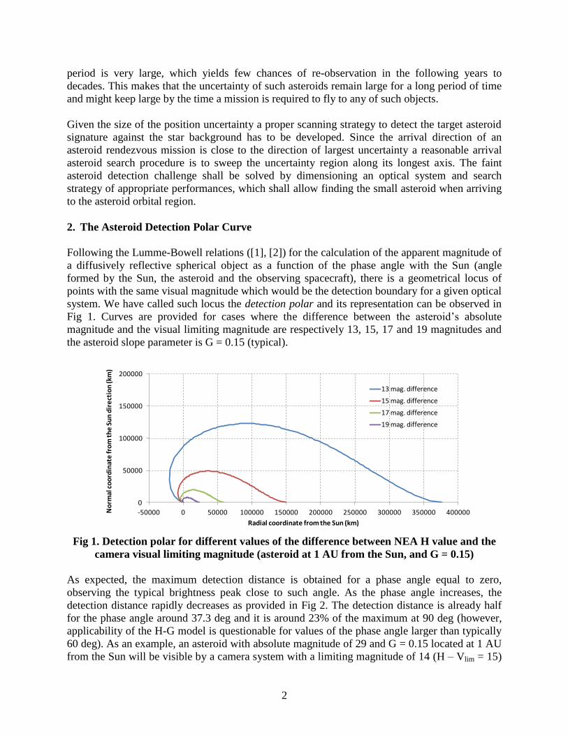
Following the Lumme-Bowell relations ([1], [2]) for the calculation of the apparent magnitude of
a diffusively reflective spherical object as a function of the phase angle with the Sun (angle
formed by the Sun, the asteroid and the observing spacecraft), there is a geometrical locus of
points with the same visual magnitude which would be the detection boundary for a given optical
system. We have called such locus the detection polar and its representation can be observed in
Fig 1. Curves are provided for cases where the difference between the asteroid’s absolute
magnitude and the visual limiting magnitude are respectively 13, 15, 17 and 19 magnitudes and
the asteroid slope parameter is G = 0.15 (typical).
Fig 1. Detection polar for different values of the difference between NEA H value and the
camera visual limiting magnitude (asteroid at 1 AU from the Sun, and G = 0.15)
As expected, the maximum detection distance is obtained for a phase angle equal to zero,
observing the typical brightness peak close to such angle. As the phase angle increases, the
detection distance rapidly decreases as provided in Fig 2. The detection distance is already half
for the phase angle around 37.3 deg and it is around 23% of the maximum at 90 deg (however,
applicability of the H-G model is questionable for values of the phase angle larger than typically
60 deg). As an example, an asteroid with absolute magnitude of 29 and G = 0.15 located at 1 AU
from the Sun will be visible by a camera system with a limiting magnitude of 14 (H – Vlim = 15)
0
50000
100000
150000
200000
-50000 0 50000 100000 150000 200000 250000 300000 350000 400000No
rmal
co
ord
inat
e fr
om
th
e S
un
dir
ect
ion
(km
)
Radial coordinate from the Sun (km)
13 mag. difference
15 mag. difference
17 mag. difference
19 mag. difference

3
at a maximum distance of 150,000 km for zero aspect angle. If the aspect angle is 45 deg, the
camera will be able to detect the asteroid at 68,000 km.
Fig 2. Detection distance for a H – Vlim = 15 (asteroid at 1 AU from the Sun, and G = 0.15)
All the above suggests that a detection campaign for such small asteroids shall be composed of
two processes, which are explained in the next sections:
A search procedure in position, by which the spacecraft sweeps the area occupied by the
asteroid covariance ellipsoid
A scan procedure in orientation for a given position, by which the camera subsystem
searches for the asteroid within the detection polar
3. Proposed Search Procedure in Position
The asteroid uncertainty region in position can be characterised approximately as an elongated
ellipsoid in space. If the detection region is small compared to the uncertainty region, it is clear
that a search procedure in position is required to try finding the asteroid in the uncertainty
ellipsoid. The search procedure will then be characterised by a sweeping strategy of the
uncertainty region which, for operational simplicity, will be approximated by a large rectangular
parallelepiped or cuboid which shall contain the whole uncertainty region. By performing such
approximation, the uncertainty region can be swept in a systematic manner by also assuming that
the detection region (the one that can be covered by the spacecraft located at a given position) is
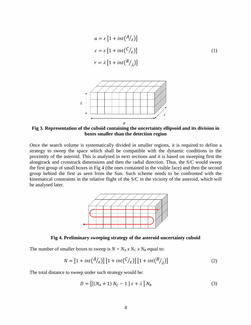
modelled by a smaller box. Thus, the large uncertainty ellipsoid can be divided in smaller boxes,
as represented in Fig 3.
Let us assume that the small box contained within the detection region is defined by a long
dimension and by a square of side length equal to . If the asteroid uncertainty ellipsoid has
dimensions A, C and R respectively in the alongtrack, crosstrack and radial directions as seen
from the Sun, the dimensions of the cuboid enclosing the ellipsoid will be:
0
25000
50000
75000
100000
125000
150000
175000
0 30 60 90 120 150 180
De
tect
ion
dis
tan
ce (
km)
Phase angle (deg)
4
(1)
Fig 3. Representation of the cuboid containing the uncertainty ellipsoid and its division in
boxes smaller than the detection region
Once the search volume is systematically divided in smaller regions, it is required to define a
strategy to sweep the space which shall be compatible with the dynamic conditions in the
proximity of the asteroid. This is analysed in next sections and it is based on sweeping first the
alongtrack and crosstrack dimensions and then the radial direction. Thus, the S/C would sweep
the first group of small boxes in Fig 4 (the ones contained in the visible face) and then the second
group behind the first as seen from the Sun. Such scheme needs to be confronted with the
kinematical constraints in the relative flight of the S/C in the vicinity of the asteroid, which will
be analysed later.
Fig 4. Preliminary sweeping strategy of the asteroid uncertainty cuboid
The number of smaller boxes to sweep is N = NA x NC x NR equal to:
(2)
The total distance to sweep under such strategy would be:
(3)

5
If we assume a constant sweep velocity w, the required time to sweep the whole volume, and
thus the maximum time required to find the asteroid in the search phase, is:
(4)
In the above derivation it is assumed that the asteroid keeps the same distance about the Sun for
the period in which the search takes place, which can be approximately true for short periods of
time. For a more general assessment it shall be considered that the asteroid translates about the
Sun in its orbital motion and thus:
the distance to the Sun changes, changing the size of the detection region
the size of the dispersion ellipse has a periodic behaviour along the orbit plus a temporal
increase due mainly to the uncertainty in orbital period
The above makes that a more generic search strategy shall not generally assume a constant size
of the uncertainty area if the search period is longer than a few weeks. However, we shall assume
in this assessment that the size of the uncertainty region and the size of the detection region are
constant in time.
4. Proposed Scan Procedure in Orientation
Having proposed an asteroid search strategy by sweeping the whole uncertainty region, we need
to now know how to dimension the small search box. Let us assume that the S/C is located
facing one of the small search boxes and oriented to observe the space in the radial direction
away from the Sun. It is desired to try finding the asteroid within the detection region. Let us
take an example form the ones above exposed, which is the one with a difference of 15
magnitudes between the asteroid absolute magnitude and the limiting visual magnitude of the
optical sensor used. The resulting detection region is provided in Fig 5.
Fig 5. Detection region for H – Vlim = 15 (asteroid at 1 AU from the Sun, and G = 0.15)
-80000
-60000
-40000
-20000
0
20000
40000
60000
80000
-40000 -20000 0 20000 40000 60000 80000 100000 120000 140000 160000 180000 200000
No
rmal
co
ord
inat
e fr
om
th
e S
un
dir
ect
ion
(km
)
Radial coordinate from the Sun (km)

6
We shall try defining a boxed region such that the previous search procedure can be applied. The
most precise approach would be to use the shape of the detection polar, however, its complex
shape advices approximating its volume by a box to facilitate the overall search and scan
process. Assuming that for each search box we shall cover a maximum viewing angle , the
geometry proposed in Fig 6 can be used to determine the maximum cubic volume where
visibility can be ensured. Such volume is the one contained by the detection polar within the
angle. Such box provides the required values of and needed in the previous section. Being the
actual polar a three-dimensional shape, the enclosure of a box within the 3D polar would require
taking a dimension instead of just if the box is equal in the alongtrack and crosstrack
directions, which is actually assumed in this analysis.
Fig 6. Proposed geometry for the scanning in search for the asteroid in the detection region
For each given angle there is a free parameter (either or ) for the definition of the scan box,
which can be used to maximise the scanned volume 2. Such maximum volume can be then
mapped as a function of the angle to observe the dependence the optimum values of and
with . Such optimum values are provided in Fig 7 as function of the beta angle after having
performed a rough optimisation process (that is the reason for the irregularities in the shape of
the curves) in the example case taken.
In a more general case the value of can be different in the alongtrack a and the crosstrack c
directions. In such case:
(5)
Once a value of the angle is selected for the mission, the scan process has to ensure that the
selected solid angle is scanned by the S/C and the camera subsystem in search for the asteroid.
-80000
-60000
-40000
-20000
0
20000
40000
60000
80000
-40000 -20000 0 20000 40000 60000 80000 100000 120000 140000 160000 180000 200000
No
rmal
co
ord
inat
e fr
om
th
e S
un
dir
ect
ion
(km
)
Radial coordinate from the Sun (km)

7
Fig 7. Optimal values of the detection box dimensions (rough optimisation) vs. beta angle
for H – Vlim = 15 (asteroid at 1 AU from the Sun, and G = 0.15)
Given a field of view (FOV) f for the optical system and a percentage p of linear overlap between
images to ensure certain margin in the image processing, the required number of images to cover
the region to scan shall be:
(6)
As an example, for a angle of 45 deg, a FOV of 5 deg and a 10% overlap between images up to
100 images would need to be taken to cover the full region within the selected detection box.
Then, this would need to be repeated in the following boxes.
In the design process of the sensor system and the detection strategy, given a limiting magnitude
of the camera system V, the FOV has to be determined and then has to be selected such that
the scanning process can be carried out in a limited amount of time and with the processing
capabilities provided to the spacecraft. This shall impose that the angle is not too large in order
to make feasible the process. Fig 8 provides the number of images required to cover the solid
angle for FOV of 5 deg, 10 deg and 15 deg.
Given a constant sweep velocity w, the magnitude (which is the distance between collateral
boxes) is covered in the following time:
(7)
which is the maximum time available to take and process the required number of images.
Assuming a time margin m used for other purposes and that the taking and processing of an
image requires a time interval tp, the following is a constraint affecting the related parameters:
(8)
0
10000
20000
30000
40000
50000
60000
70000
80000
90000
100000
0 30 60 90 120 150 180
Lon
gitu
de
(km
)
Beta angle (deg)
Epsilon
Lambda

8
The above shall ensure that the processing can be performed with the available resources and
system constraints.
Fig 8. Number of required images to cover the detection box versus beta angle for different
camera field of views for H – Vlim = 15 (asteroid at 1 AU from the Sun, and G = 0.15)
5. Dynamical Environment for the Search Phase
The proposed sweep strategy to search for the asteroid implies that the relative motion of the S/C
around the average asteroid orbit will need to be such that the S/C is forced to follow the
specified path. This implies a limitation on the sweep speed which is the one that can be ensured
with the S/C propulsion system and will also imply a certain fuel consumption and search time.
Those parameters shall be also evaluated in order to determine the solution space of application
for the design of a given mission. For example, requirements on the following elements will help
in constraining the definition of the system parameters:
Maximum search time (e.g. 3 months)
Maximum fuel consumption for search purposes (a given percentage of the boarded fuel)
Minimum sweep velocity (related to the maximum search time but also depending on the
maximum size of the uncertainty region and the available thrust modulus)
Several parameters defining the mission scenario and timeline during the search phase must be
traded off in order to analyse in detail the feasibility of searching and successfully finding the
intended NEA.
NEA orbit uncertainty: the knowledge about the asteroid orbit determines the volume
that must be swept and scanned with the S/C and the optical sensor in search of the
asteroid. Obviously, the less uncertain the asteroid orbit, the shorter the search phase.
Optical sensor features: the ability to detect the asteroid is largely determined by the
features of the optical sensor. An important feature of the optical sensor is its FOV: the
larger the FOV, the wider the sky sector that can be imaged without requiring additional
0
50
100
150
200
250
300
350
400
450
0 15 30 45 60 75 90
Nu
mb
er
of
imag
es
Beta angle (deg)
FOV = 5 deg
FOV = 10 deg
FOV = 15 deg

9
manoeuvres; however, detection of faint objects call necessarily for narrow FOV, hence
imposing the need of a certain manoeuvring profile to guarantee the systematic search of
an asteroid. Another important parameter to take into account is the exposure time to
achieve a given visual magnitude.
Search phase duration: the search phase duration must be generally limited in time.
This means that an active search must be implemented in this phase and a large enough
control authority must be allowed for the mission. The trade off, hence, in what regards
the duration of this phase, is related to the determination of the minimum thrusting
capabilities the S/C should be given in order to keep a reasonable time interval during
which finding the asteroid is guaranteed.
In order to sweep the uncertainty region in a reasonable amount of time, it is required to allow a
forced motion of the spacecraft in the vicinity of the asteroid orbit. Such forced motion can be
efficiently implemented by means of low-thrust, which could be already in place in order to
perform the transfer from the Earth to the asteroid. The idea is to continuously push the S/C in
order to make it follow a prescribed evolution in relative motion. In this way phase duration
could be reduced, at the expense of increasing cost in terms of delta-V, and hence, propellant
mass.
A forced drift in alongtrack direction can be obtained by pushing in radial direction, as shown in
Fig 9 (left) and once certain initial relative velocity wrt the asteroid is achieved. It shall be
assumed that the satellite possesses the intended relative drift velocity at the beginning of this
phase, which can be obtained by proper targeting to this dynamics state at the end of the former
transfer phase.
Fig 9. Forced, low thrust motion alongtrack (left) and in radial direction (right)
The obtained drift in alongtrack velocity DV for a given low-thrust acceleration in the radial
direction can be approximated for circular orbits by the following formula:
(9)
Where R is the radius of the orbit about the Sun and S the gravity constant of the Sun.

10
The parameters entering the analysis are then:
Drift velocity (i.e., km/day);
Maximum thrust to mass ratio needed to keep the intended drift velocity
Cost of low thrust profile (i.e, m/s per 100,000 km)
Figure 10 below shows the maximum thrust needed to keep several different initial drift
velocities at 1 AU, expressed in drift distance per day for a 400 kg S/C. For instance, this plot
shows that a maximum low-thrust capability of 30 mN allows keeping a drift velocity of 16,000
km/day, which results in 6.25 days for a 100,000 km total drift. It also follows that a low-thrust
level of 30 mN would suffice to cope with uncertainty ellipsoids of 500,000 km in just 1 month.
Furthermore, 10 mN would be enough to sweep 500,000 km if 3 months are allowed for this
search operation.
Fig 10. Maximum thrust required to keep a certain drift velocity alongtrack with a low-
trust profile
In what regards the cost of this manoeuvre, around 40 m/s per 100,000 km would be needed for a
400 kg S/C. The reason why this cost is independent of the drift velocity is that while keeping a
faster velocity might be more expensive, it also allows a faster scanning of a certain distance, so
both effects counteract for a given distance to cover.
On the other hand and if the uncertainty ellipsoid is sufficiently large in the radial direction, it
will be necessary to move in that direction and thus command a dedicated manoeuvre following
a prescribed path with the help of a low thrust profile (forced motion represented in Fig 9 right).
Results for such motion provided in Fig 11 show that, for instance, in the case of a 30 mN of
maximum thrust, it is possible to move by 5,000 km in radial direction in less than 6 days.
Assuming a size of the uncertainty ellipsoid in radial direction of 50,000 km and a scan box of
maximum 25,000 km, the same magnitude needs to be covered to move to the second half of the
uncertainty region, which for a maximum 30 mN low thrust corresponds to a transfer time of
about 1 month.
0 0.2 0.4 0.6 0.8 1 1.2 1.4 1.6 1.8 2
x 104
0
5
10
15
20
25
30
35
40
Maximum thrust required to keep a certain drift along track
drift velocity, km/day
Ma
xim
um
th
rus
t n
ee
de
d f
or
40
0k
g S
C, m
N

11
Fig 11. Maximum thrust required to move in radial direction a given distance in a given
time (left) and cost of such low thrust manoeuvre (right)
Regarding the trade-off to be solved about the scanning strategy two possibilities arise:
Scan first alongtrack at a certain radial distance, in order to iterate this scanning for
different radial distances, Fig 12 left; or:
Scan first in radial direction, advancing sequentially to different alongtrack locations to
scan again in the radial direction, Fig 12 right.
Fig 12. Scanning trade-off: first alongtrack, after radial (left), or first radial, after
alongtrack (right)
Typically the first strategy is more efficient and it is selected as baseline. Something similar
applies when the size of the uncertainty region in the crosstrack direction is larger than the scan
capability in that direction. Sweeping at different positions in cross-track direction would be
required. Such case is not further analysed here.
Optimally, one would desire not to have to perform sweep manoeuvres in the radial and the
crosstrack directions, thus only in the alongtrack direction. This would allow optimising the time
allocated to the search phase and the required thrust for this phase. Such a solution is pursued in
the following section.
2 4 6 8 10 12 14 16 18 200
20
40
60
80
100
120
Maximum thrust required for forced radial profile
manoeuvre duration, days
Ma
xim
um
th
rus
t n
ee
de
d f
or
40
0k
g S
C, m
N
500km
1000km
1500km
2000km
2500km
3000km
3500km
4000km
4500km
5000km
2 4 6 8 10 12 14 16 18 200
10
20
30
40
50
60
70
80
Cost of a forced radial profile
manoeuvre duration, days
Co
st
in m
/s f
or
a 4
00
kg
SC
500km
1000km
1500km
2000km
2500km
3000km
3500km
4000km
4500km
5000km

12
6. Example Application Case
6.1. The Sweeping Solution
In the following, the case of asteroid 2008 JL24 is analysed. It has an absolute magnitude of 29.6
a period of 386.4 days and an aphelion of 1.15 AU (assumed as applicable distance). A slope
parameter of G = 0.15 is assumed. The mapped uncertainty in the alongtrack direction by year
2030 is about 80,000 km (1-sigma), which implies an uncertainly region (two sides of the 3-
sigma uncertainty) of about 500,000 km. The 6-sigma uncertainty in crosstrack direction is about
1,000 km and in radial direction of about 50,000 km.
As discussed in section 2, it is possible to graphically represent the detection region for an
asteroid of a certain absolute magnitude, given the limiting magnitude of the optical sensing
device mounted on the S/C. Assuming the case of asteroid 2008 JL24, it is possible to draw the
mentioned detection polars for different visual magnitudes of the camera, as given in Fig 13 for
visual limit magnitudes between 12 and 15 magnitudes.
Fig 13. Detection polar for different values of the camera limit visual magnitude (asteroid
2008 JL24 at 1.15 AU from the Sun, and G = 0.15)
Regarding the search strategy proposed in 4 and 5, we assume that the preferred search process
will be based on the following aspects:
It is preferred not to have to sweep the uncertainty region in the crosstrack direction, but
just cover the uncertainty in such direction by an attitude scanning with the S/C to take
the required images of the out-of-plane regions. This shall prevent from performing
costly out-of-plane manoeuvres to sweep the ellipsoid. This preference is not considered
as very constraining due to the small out-of-plane uncertainties presented by this asteroid.
It is preferred not to have to sweep the uncertainty region in the radial direction, but just
have enough camera visual limit magnitude to cover the full uncertainty region in the
radial direction. This is certainly a constraining condition in the specification of the
camera performances, as the detection polar shall then cover the whole uncertainty region
within the radial direction, thus dimensioning the limit visual magnitude of the camera.
0
20000
40000
60000
80000
-20000 0 20000 40000 60000 80000 100000 120000 140000 160000 180000No
rmal
co
ord
inat
e fr
om
th
e S
un
dir
ect
ion
(km
)
Radial coordinate from the Sun (km)
V = 15 mag
V = 14 mag
V = 13 mag
V = 12 mag

13
Accepting the above assumptions for the example mission, it shall be possible to cover the full
uncertainty region by just one pass in the alongtrack direction covering the 500,000 km
uncertainty region in such direction as represented in Fig 14. Each of the smaller elongated
parallelepipeds is the one contained in the detection polar presented in Fig 15. Within each of
them, a scan in attitude will be performed to find the asteroid. Assuming, that the 50,000 km of
radial distance are to be covered ( parameter), plus the separation between the S/C and the
search region (δ parameter of around 20,000 km) it is observed in Fig 13 that the limit detection
magnitude has to be between 13 and 14 magnitudes.
Fig 14. Proposed sweeping strategy in position of the asteroid uncertainty parallelepiped
Fig 15. Relative geometry of S/C and detection box with the magnitudes given in Fig 6
6.2. The Scanning Solution
Once the desired detection polar and sweeping strategy have been sized, it is required to define
the scanning solution and to check what are the available cameras that can meet the required
detection performance. Clearly, the OSIRIS cameras in Rosetta would be oversized for a small
mission both in performances and in mass requirements. However, if we stay with European
developed cameras (ONR is from US and AMICA Japanese) the Dawn Framing Camera (FC)
appears as a very promising solution. FC has been declared as able of detecting magnitude 16
objects in exposure time of 10 min [3].
Table 1 provides a summary of information found on some currently available cameras.
Clearly, the OSIRIS cameras in Rosetta would be oversized for a small mission both in
performances and in mass requirements. However, if we stay with European developed cameras
(ONR is from US and AMICA Japanese) the Dawn Framing Camera (FC) appears as a very
A
C R
Spacecraft
A
C R
c
a
Detection box

14
promising solution. FC has been declared as able of detecting magnitude 16 objects in exposure
time of 10 min [3].
Table 1. Relevant properties of some space qualified cameras
Camera OSIRIS NAC OSIRIS
WAC AMIE
Framing
camera ONR AMICA
Mission Rosetta Rosetta SMART-1 Dawn MRO Hayabusa
Pixel matrix 2048 x 2048 2048 x 2048 1024 x 1024 1024 x 1024 1024 x 1024 1024 x 1000
FOV (deg) 2.35 x 2.35 12.1 x 12.1 5.3 x 5.3 5.5 x 5.5 1.4 x 1.4 5.83 x 5.69
Focal length (mm) 717 140 155 150 - 120.8
Aperture (mm) 89.6 25.0 15.5 20.0 - -
f 8 5.6 10 7.5 - -
iFOV (microrad) 20.0 103.1 90.3 93.7 23.9 98.0
Limiting
magnitude 16 - -
16 in 10 min
exposure 12 -
Mass (kg) 13.2 9.5 2.1 2.5 2.7 -
Power (W) - - 9 6 5 -
NB: empty cells mean that no information could be found on such parameter
Making use of the relation that permits obtaining the exposure times for different visual
magnitudes, it is possible to derive the exposure times represented in Fig 16. For a visual
magnitude of 13 the exposure time is 38 s, while for V = 14 the exposure time is 95 s.
Fig 16. Exposure time vs. visual magnitude for the Framing Camera
If we take the FC, we can evaluate performances in terms of the parameters dimensioning the
sweep strategy. In particular and assuming that while the S/C is scanning a given detection box
there is no thrust, and when the required images are taken the S/C moves to the following box,
we can evaluate the following parameters as function of the detection magnitude and the viewing
angle in the alongtrack direction (the beta angle in Fig 6):
The required number of camera shots within each detection box (Fig 17).
The ratio of time devoted to image taking versus total available time for search (Fig 18).

15
The required thrust for the search phase (Fig 19).
The resulting linear magnitudes defined in Fig 6 dimensioning the size of the detection
box (lambda, which is equal to 50,000 km and epsilon given in Fig 20) and the distance
from the S/C to the detection box (delta, given in Fig 22).
Additional assumptions taken for this particular assessment were the following:
Maximum available thrust for sweep manoeuvre at 1 AU: 18 mN (corresponding to the
maximum of the RIT-10 engine)
Spacecraft mass to dimension required force: 450 kg
Maximum time available to sweep: 90 day
Varying viewing angle (beta) in crosstrack direction: 10 deg, 30 deg, 60 deg, 90 deg and
120 deg
Scan overlap between images: 10%
S/C attitude reconfiguration time between images: 60 s
The H-G approximation to asteroid radiance used in these computations is typically valid up to
values of the solar aspect angle of 60 deg, which translates into a maximum viewing angle in the
alongtrack direction of 120 deg. That is the reason for selecting viewing angles between 10 deg
and 120 deg in this assessment. As expected, Fig 17 allows noticing that the larger the viewing
angle, the larger the number of shots to cover the detection box. The dependence observed with
the limit magnitude comes from the fact that for smaller V values it is required to come closer to
the asteroid expected orbit and this makes that the number of shots in the crosstrack direction are
increased to cover the 5,000 km band, and opposite for increasing V values.
Fig 17. Total number of required shots vs. limit visual magnitude and viewing angle (beta)
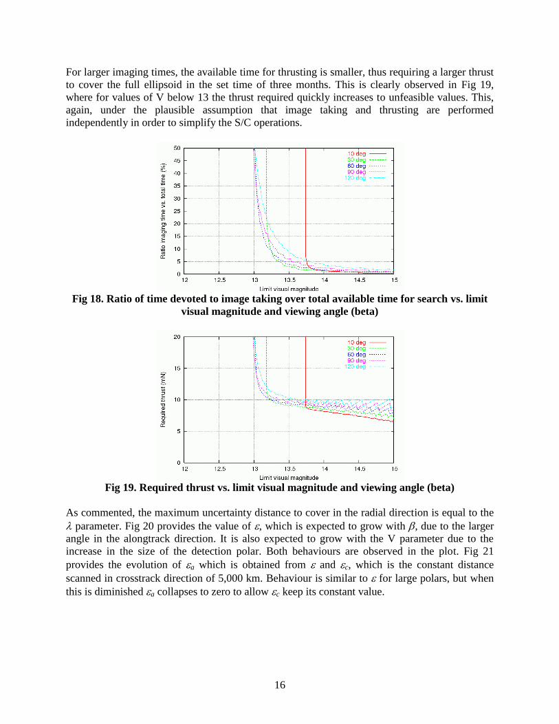
Fig 18 shows that for large V values the need of less images requires of less total time compared
to the maximum available time for search, even if requiring larger exposure times. Thus the
increase in the number of required images (with smaller exposure time) is more relevant than the
increase in exposure time (for smaller number of images required). The increase in imaging time
shoots up for smaller V values, setting a limit in minimum visual magnitude at around V = 13.
16
For larger imaging times, the available time for thrusting is smaller, thus requiring a larger thrust
to cover the full ellipsoid in the set time of three months. This is clearly observed in Fig 19,
where for values of V below 13 the thrust required quickly increases to unfeasible values. This,
again, under the plausible assumption that image taking and thrusting are performed
independently in order to simplify the S/C operations.
Fig 18. Ratio of time devoted to image taking over total available time for search vs. limit
visual magnitude and viewing angle (beta)
Fig 19. Required thrust vs. limit visual magnitude and viewing angle (beta)
As commented, the maximum uncertainty distance to cover in the radial direction is equal to the
parameter. Fig 20 provides the value of , which is expected to grow with , due to the larger
angle in the alongtrack direction. It is also expected to grow with the V parameter due to the
increase in the size of the detection polar. Both behaviours are observed in the plot. Fig 21
provides the evolution of a which is obtained from and c, which is the constant distance
scanned in crosstrack direction of 5,000 km. Behaviour is similar to for large polars, but when
this is diminished a collapses to zero to allow c keep its constant value.

17
Fig 20. Resulting epsilon distance vs. limit visual magnitude and viewing angle (beta)
Fig 21. Resulting epsilon-alongtrack distance vs. limit visual magnitude and viewing angle
(beta)
Regarding the δ distance defined in Fig 6 as the distance between the S/C and the detection box,
this is provided in Fig 22, showing an expected growth with the size of the detection polar (i.e.
the V parameter) and also a growth when the viewing angle is reduced, which can be explained
by the effect that keeping constant has on the distance S/C-box which increases as the
detection polar elongates in the radial direction.
Given the 18 mN available for thrusting, limit visual magnitudes above 13.5 are feasible as given
in Fig 19 for all viewing angles except 10 deg. However the number of required images per
detection box would be rather high and, consequently, the ratio of imaging time. If we would like
to have, for operational reasons, a maximum of 10% of the time during the search phase for
imaging purposes and 90% for thrusting, we could ensure such values for all the considered beta
angles above 30 deg by setting the minimum value of V at 13.5 magnitudes as derived from Fig
18. The exposure time for each image at that value of V is 60 s. It is clear that certain degree of
spacecraft stability in attitude would need to be ensured to achieve such performances.
The resulting detection distance for H = 29.6 and V = 13.5 can be observed in Fig 23. Fig 24
provides the resulting polar.

18
Fig 22. Resulting delta distance vs. limit visual magnitude and viewing angle (beta)
Fig 23. Detection distance as function of the phase angle for H=29.6 and V=13.5
Fig 24. Detection polar for H=29.6 and V=13.5 and detection box for =60 deg
0
25000
50000
75000
100000
0 30 60 90 120 150 180
De
tect
ion
dis
tan
ce (
km)
Phase angle (deg)
-45000
-30000
-15000
0
15000
30000
45000
-15000 0 15000 30000 45000 60000 75000 90000 105000
No
rmal
co
ord
inat
e fr
om
th
e S
un
dir
ect
ion
(km
)
Radial coordinate from the Sun (km)

19
In addition, the detection box is derived for a viewing angle of 60 deg. In this case the values are
the following:
= 50,000 km, δ = 12,117 km, = 13,992 km and a = 13,068 km
Number of boxes alongtrack: 39
Number of shots in crosstrack and alongtrack directions within detection box: 5 and 13
Imaging time ratio: 3.9%, well below 10% in this case
Effective thrust: 9.47 mN
7. Conclusions
An efficient strategy has been proposed to the task of finding a very small asteroid (absolute
magnitudes between 28 and 30) within its uncertainty region in a limited amount of time by
combining a low-thrust sweeping strategy and an attitude scanning process. Requirements on the
determination of the required low-thrust acceleration and the camera performances have been
derived as a function of the asteroid properties and the size of the uncertainty region.
A camera solution and a detection strategy have been derived to find asteroid 2008 JL24 in three
months and sweeping an uncertainty region with a maximum dimension alongtrack of 500,000
km, crosstrack of 5,000 km and radial of 50,000 km. It has been assessed that under such
conditions a camera and operating concept with a limiting magnitude of 13.5 should be enough
to solve the detection of such small asteroid provided the uncertainty region is scanned in the
alongtrack direction in the available amount of time. The Dawn Framing Camera has been found
to be an appropriate solution for this strategy.
8. Acknowledgements
The work presented in this paper was performed within following ESA contract: SysNova,
Sustainable near-Earth Access and Life Support System (SEALS): Contactless Asteroid Orbit
Modification System (AO/1-7197/12/F/MOS). The related study performed within that contract
was the following: Modification of the Orbit of a Small Asteroid with Ionic Collisions (MOSAIC)
which was led by Universidad Politécnica de Madrid with Elecnor Deimos as subcontractor.
9. References
[1] Lumme, K. and Bowell, E. “Radiative Transfer in the Surfaces of Atmosphereless Bodies. I.
Theory”, The Astronomical Journal, Vol. 86, No. 11, pp. 1694-1704 November 1981
[2] Lumme, K. and Bowell, E. “Radiative Transfer in the Surfaces of Atmosphereless Bodies. II.
Interpretation of Phase Curves”, The Astronomical Journal, Vol. 86, No. 11, pp. 1705-1721
November 1981
[3] Sierks, H. et al. “Dawn Framing Camera: A Telescope En Route to the Asteroid Belt”, MPS /
DLR / IDA