vertical vibrations of composite bridge/track structure ...yadda.icm.edu.pl/.../c/podworna.pdf ·...
TRANSCRIPT

BULLETIN OF THE POLISH ACADEMY OF SCIENCES
TECHNICAL SCIENCES, Vol. 62, No. 1, 2014
DOI: 10.2478/bpasts-2014-0018
Vertical vibrations of composite bridge/track structure/high-speed
train systems. Part 1: Series-of-types of steel-concrete bridges
M. PODWORNA1 and M. KLASZTORNY2∗
1 Institute of Civil Engineering, Wroclaw University of Technology, 27 Wyspianskiego St., 50-370 Wroclaw, Poland2 Department of Mechanics and Applied Computer Science, Military University of Technology, 2 Kaliskiego St., 00-908 Warsaw, Poland
Abstract. A new series-of-types of single-span simply-supported railway composite (steel-concrete) bridges, with a symmetric platform, has
been designed according to the Polish bridge standards. The designed bridges/viaducts are located on the main railways of the classification
coefficient k = +2. A ballasted track structure adapted to high operating speeds has also been designed. The ultimate limit states and
the limit states corresponding to the bridges undertaken are collected and discussed. The bridges have been designed in accordance with
contemporary art engineering, with geometric and material optimization, avoiding overdesign. A new methodology of numerical modelling
and simulation of dynamic processes in composite bridge/ballasted track structure/high speed train systems, developed in Part 2 and Part 3,
has been applied and implemented in a problem-oriented computer programme. A new approach to predicting forced resonances in those
systems is formulated and tested numerically. It has been proved that in the case of typical structural solutions of bridges and ballasted track
structures, it is necessary to introduce certain limitations for operating speeds of trains.
Key words: composite steel-concrete bridge, ballasted track structure, high-speed train, design, FE modelling, simulation, forced resonances,
numerical analysis.
1. Introduction
Composite (steel-concrete) bridges loaded by high-speed
trains need to be designed or modernized to ensure the traf-
fic safety condition (TSC) and the passenger comfort con-
dition (PCC), among the others (EN 1990 Eurocode: Ba-
sis of structural design. Annex A2: Application for bridges,
2004). Too large vertical accelerations of the bridge platform
may cause ballast destabilization in the track structure. This
problem was investigated at ERRI to establish the safe limits
(ERRI. D214/RP9, Part B, Rail bridges for speeds >200 km/h,
Utrecht, The Netherlands, European Rail Research Institute,
1999), later incorporated in EN 1990 Eurocode: Basis of
structural design. Annex A2: Application for bridges, 2004,
EN 1991-2, Eurocode 1: Actions on structures. Part 2: Gener-
al actions – traffic loads on bridges, 2003, in which dynamics
of railway bridges under high-speed trains is standardized. To
date, each railway bridge has been designed singly.
The study presents a series-of-types of single-span simply-
supported railway composite (steel-concrete) bridges, with
a symmetric platform, as well as a ballasted track struc-
ture adapted for high-speed trains, both designed according
to Polish standards PN-85/S-10030. Bridge objects. Loads,
PN-82/S-10052. Bridge objects. Steel structures. Design, PN-
91/S-10042. Bridge objects. Concrete, reinforced concrete
and pre-stressed concrete structures. Design. A new method-
ology of numerical modelling and simulation of dynamic
processes in a composite bridge/ballasted track structure/high
speed train (BTT) system, developed by Podworna and Klasz-
torny [1], has been applied. Computer algorithms of FE
modelling and simulation have been programmed in Del-
phi [2]. Both, static and dynamic numerical investigations
of the bridges forming the series-of-types have been carried
out. It has been proved that in the case of typical structural
solutions of bridges and ballasted track structures, it is nec-
essary to introduce certain limitations for service speeds of
trains. Extended literature review results in dynamics of rail-
way bridges loaded by high-speed trains is presented in [1].
2. Series-of-types of railway bridges
The study develops design of a series-of-types of composite
(steel-concrete) railway beam bridges. There is developed a
series-of-types composed of five objects of codes and basic
geometric parameters compared in Table 1. Theoretical span
lengths 15, 18, 21, 24, and 27 m are commonly used in design
of the bridges undertaken.
Table 1
Codes and basic geometric parameters of objects forming SCB
series-of-types
Bridge code SCB-15 SCB-18 SCB-21 SCB-24 SCB-27
Theoretical span length L [m] 15.00 18.00 21.00 24.00 27.00
Total span length [m] 15.80 18.80 21.80 24.80 27.80
Structural height [m] 1.82 1.97 2.12 2.27 2.42
The SCB series-of-types of railway bridges was designed
according to standards PN-85/S-10030, PN-82/S-10052, PN-
91/S-10042, under the following assumptions:
• bridges/viaducts are located on the main railways of clas-
sification coefficient k=+2,
• axis of an unloaded railway track is rectilinear horizontal,
∗e-mail: [email protected]
165
Brought to you by | Biblioteka Glowna UniwersytetuAuthenticated | 212.122.198.172
Download Date | 5/13/14 10:31 AM

M. Podworna and M. Klasztorny
• track gauge is adapted for high-speed trains and is equal to
5.10 m,
• bridges are composite (steel-concrete) and have separate
spans for each track,
• bridges are single-track and simply supported,
• a number of railway tracks is optional.
A reference object is a modernized composite viaduct
described in the technical documentation “Modernization of
composite viaduct KNI 140070 situated in km. 200.794 of
railway No. 4 – E 65 Grodzisk Mazowiecki – Zawiercie, Con-
struction project, Polish Railways Office, Warsaw, 2008”.
Construction of the bridges and the track is illustrated with a
case of SCB-15 bridge in Figs. 1–4. There are significant dif-
ferences between the objects of SCB series-of-types and the
reference object. The technical data of SCB series-of-types
objects are as follows:
• the superstructure is composed of four steel I-beams and a
RC plate platform,
• main steel beams are 770–1370 mm high, they are pro-
duced of S235W steel, their lower chords are reinforced
with one overlay 0.6 L long,
• the main beams are reinforced vertically and horizontally
in pairs with L100×100×10 angles using welding,
• in the supporting areas of the main beams, there are 50 mm
thick bearing plates welded to the lower chords of the main
beams and three vertical ribs welded to the I-beams,
• 10 mm thick vertical ribs, welded to the I-beam webs, are
positioned at intervals of 1500 mm,
• discrete connection of the main steel beams with the RC
platform plate is executed with the use of steel anchors
of dimensions ϕ12 mm, l = 170 mm, welded to the upper
chords of the beams and anchored in the RC platform plate;
the anchors are spaced properly in both the longitudinal and
transverse direction to protect practically non-deformable
connection,
• an RC platform plate is 250 mm thick, produced of B35
concrete and reinforced with AII/18G2-B steel,
• levelling concrete layer of 0–40 mm thickness is character-
ized by a 2% two-sided transverse slope,
• concrete kerbs of the platform plate are 250 mm high, they
are produced of B17 concrete and reinforced structurally;
there are applied a technological stop at the level of the up-
per surface of the RC platform plate and 1 cm wide vertical
dilatations at intervals of 1.50 m,
• RC bridgehead foundations are used,
• approach slabs are supported with elastomeric bearings
and produced of B35 concrete, reinforced with AII/18G2-B
steel; their dimensions are 5.00 m – total length, 4.00 m –
width, 20 cm – thickness, 2% two-sided transverse slope,
• in the transient zones, there is applied 150 kg/m3 cement-
stabilized soil,
• the track structure is composed of: continuously welded
S60 main rails, S60 side rails of length covering the bridge
span and the approach slabs, B320 U60, B320 U60-U PC
sleepers, first class crushed stone ballast to the depth of 35
cm under sleepers in the track axis, Vossloh 300-1fasteners
of the main rails, SB3 fasteners of the side rails,
• there is applied Elastomatic TF isolation which is resistant
to direct action of the ballast that eliminates application of
a protective concrete layer,
• there is applied a one-side service sidewalk (from the outer
side),
• there are applied movable bearings of RESTON type, from
the train entrance side, with a possibility of longitudinal
displacement under each main beam; bearings under the
outer beams have also transverse displacement available,
• there are applied unmovable bearings of RESTON type,
from the side opposite to the train entrance side; bearings
under the outer beams have also transverse displacement
available.
Approach slabs are designed to minimize the threshold effect,
eliminate a jump in subsidence of the ground in the area of the
bridgehead, increase durability of the track in the bridgehead
area.
Fig. 1. Cross-section of SCB-15 bridge at midspan
166 Bull. Pol. Ac.: Tech. 62(1) 2014
Brought to you by | Biblioteka Glowna UniwersytetuAuthenticated | 212.122.198.172
Download Date | 5/13/14 10:31 AM

Vertical vibrations of composite bridge/track structure/high-speed train systems. Part 1
Fig. 2. Cross-section of symmetric superstructure of SCB-15 bridge (main and structural reinforcement)
Fig. 3. Longitudinal section of symmetric bridge SCB-15 and of transient zone part
New structural properties of bridges forming the SCB
series-of-types are as follows:
• full symmetric RC platform (minimization of flexural –
torsional vibrations, elimination of vibration coupling of
parallel neighbouring spans through the ballast),
• structurally reinforced low concrete kerbs of the platform
plate, with application of technological stop and dilatations
(elimination of a one-side RC wall inducing asymmetric vi-
brations of the span and increase in lateral and flexural –
torsional vibrations),
• shell CFRP composite shields (resistant to vibrations) fixed
to the kerbstones with steel anchors, with vertical dilata-
tions 1 cm width and 1.49 m long, sustaining the ballast
between the kerbstones and decreasing the platform mass,
• four main steel I-beams joined in pairs, with the use of
vertical and horizontal brackets, with no brackets between
the beam pairs,
• bearings unmovable transversally under each inner beam
(better transfer of the horizontal loads on the main beams),
• back walls of the bridgeheads with increased thickness in
order to support the approach slabs with elastomeric bear-
ings.
Figure 1 shows a cross-section in the span centre of bridge
SCB-15. Cross-sections of bridges SCB-18, SCB-21, SCB-
24, SCB-27 are analogous; only the web and lower chords of
the main beams as well as the vertical brackets are subjected
Bull. Pol. Ac.: Tech. 62(1) 2014 167
Brought to you by | Biblioteka Glowna UniwersytetuAuthenticated | 212.122.198.172
Download Date | 5/13/14 10:31 AM

M. Podworna and M. Klasztorny
Fig. 4. Longitudinal section of transient zone and cross-sections of track outside this zone (A-A) and in approach slab zone (B-B)
to respective changes. Figure 2 presents a cross-section of a
half of the SCB-15 bridge superstructure, including transverse
main reinforcement and longitudinal structural reinforcement
of the platform plate, longitudinal and transverse structural
reinforcement of the kerbstones. The detailed geometry of the
solution is provided.
Figure 3 demonstrates a longitudinal section of bridge
SCB-15 and the initial part of the transient zone. One can see
ribs stiffening webs of steel beams at 1500 mm intervals, sup-
port ribs located every 200 mm, a bearing plate 600 mm long,
an overlay of a lower chord of the length of 0.6L = 9000 mm,
kerbstones with 1 cm dilatations every 1500 mm, CFRP com-
posite protective walls with 1 cm dilatations every 1500 mm,
an approach slab of the total length of 5000 mm. Figure 4 de-
picts the transient zone. One can see the S1 cement-stabilized
soil zone, the S2 nonwovens reinforced embankment ground,
the S3 sand–gravel mix layer under the ballast, the approach
slab. There are shown a cross-section of the track outside the
transient zone and in the approach slab zone.
Engineering calculations of bridges forming the SCB
bridge series-of-types were conducted according to PN-85/S-
10030, PN-82/S-10052, PN-91/S-10042 and [3]. The fol-
lowing construction technology of composite girders was
adopted:
• assembly on the stiff scaffolding (composite superstructure
operates only in phase II),
• no initial stresses incorporated in steel beams before their
connection to a RC platform plate,
• concrete of the platform plate produced of a mixture of
plastic consistency,
• concreting the platform plate section by section; a break
between concreting the subsequent sections ≥ 8 hours,
• concrete curing in normal conditions during 28 days.
This technology is the best one from a point of view of static
effort (under dead load) and dynamic effort (under live load)
of the composite superstructure.
In the engineering calculations the following assumptions
are adopted:
• the composite cross-section operates in a linear – elastic
range,
• steel beams – concrete platform connection is non-
deformable (linear distribution of longitudinal normal
strains at bending),
• a composite cross-section is reduced to the equivalent steel
cross-section,
• dimensioning for elastic ultimate limit states (stresses re-
sulting from design loads not exceeding design strength),
• dimensioning for limit states (displacements/vibrations in-
duced by characteristic loads not exceeding displacement
limits),
• a transverse distribution of the loads corresponds to the
rigid cross-member assumption,
• torsional stiffness of the composite superstructure is not
considered (bracings connect main beams in pairs),
• ribs of the main I-beams meet the requirements set for stiff
ribs.
168 Bull. Pol. Ac.: Tech. 62(1) 2014
Brought to you by | Biblioteka Glowna UniwersytetuAuthenticated | 212.122.198.172
Download Date | 5/13/14 10:31 AM

Vertical vibrations of composite bridge/track structure/high-speed train systems. Part 1
Complete engineering calculations include [3]:
1. stresses induced by dead loads (with assembly technology
taken into consideration),
2. stresses induced by vertical live loads (vertical moving
load),
3. stresses induced by rheological effects (concrete creep and
shrinkage with creep taken into consideration),
4. stresses induced by horizontal live loads (wind load, lateral
impacts of moving trains),
5. stresses induced by thermal effects.
In the case of the basic system of loads (P), stresses of the
1, 2, 3 types are taken into account. In the case of the basic
and additional systems of loads (PD), stresses of the 1, 2, 3, 4,
5 types are taken into account. In the case of the basic and ex-
ceptional systems of loads (PW), exceptional loads, e.g., train
derail, are also taken into account. The least advantageous
system (P, PD or PW) is accepted for the dimensioning.
Complete check-up of elastic ultimate limit states includes
[3]:
1. check the composite girder load capacity (longitudinal nor-
mal strains, shear),
2. check the RC platform plate load capacity,
3. check the steel beams for fatigue,
4. check the steel beams – RC platform plate connection load
capacity,
5. check the welded joints and other joints of bridge span
elements,
6. check the compressed chords of the steel beams for lateral-
torsional buckling (absent in the applied solution),
7. check the load capacity for local stability of I-beam webs,
8. check the position stability of bridge spans (overturning or
sliding).
In the case of check-up 1, 2, 4, 5, 6, 7, there are the de-
sign stresses, dynamic coefficient and design strengths taken
into account. In the case of check-up 3, there are the charac-
teristic stresses, dynamic coefficient, fatigue coefficient mzm
(PN-82/S-10052), design strengths taken into account. In the
case of check-up 8, the characteristic loads (without dynamic
coefficient) are taken into consideration.
Check-up of connection of the steel part with the concrete
part includes (PN-82/S-10052):
• load capacity of connectors,
• load capacity of fixing to steel girders,
• load capacity of concrete around a connector.
Complete check-up of limit states includes [3]:
1. check the deflection of a composite girder under moving
load,
2. check the horizontal stiffness of a bridge,
3. design of the negative structural deflection,
4. check the concrete crack limit state (initiation and opening
of transverse cracks; absent in case of applied solution and
construction technology),
5. check the fatigue limit state (durability protection of com-
posite bridge),
6. check the limit state of comfort,
7. check limit states of rail traffic safety:
• vertical vibrations of a bridge,
• torsion of a platform,
• rotations at the ends of a platform,
• horizontal deformations of a platform.
The present work considers the following stresses in di-
mensioning of a composite cross-section of SCB series-of-
types bridge objects:
• stresses induced by dead loads (with assembly technology
taken into consideration),
• stresses induced by vertical live loads (vertical moving
load),
• stresses induced by rheological effects (concrete creep and
shrinkage with creep taken into consideration).
This is the basic load system (P). The ultimate limit state
results in check-up of the composite girder load capacity (lon-
gitudinal normal stresses). The limit states include:
• check the deflection of a composite girder under moving
load,
• check the fatigue limit state (durability protection of com-
posite bridge),
• check the limit state of comfort,
• check the limit state of rail traffic safety in the scope of
vertical vibrations of a bridge.
Material constants for the main materials (concrete, steel)
are collected in Tables 2–4 [3].
Table 2
Material constants for B35 (C30/37) concrete of platform plate [3]
characteristic compressive strength fck 26.2 MPa
average value of compressive strength
with 50% probability of exceeding
fck 0.5 = fcm 34.2 MPa
average value of tensile strength with
5% probability of exceeding
fctk 0.05 1.9 MPa
average value of tensile strength with
50% probability of exceeding
fctk 0.5 = fctm 2.7 MPa
elastic modulus (0 < σ ≤ 0.5fck) Ecm 34.6 GPa
Poisson’s ratio ν 0.167
coefficient of thermal expansion α 1 × 10⁻⁵/K
Table 3
Material constants for 18G2-B reinforcing steel (weldable) [3]
nominal diameter of rods d 6–32 mm
characteristic yield stress fyk 355 MPa
characteristic strength ftk 480 MPa
elastic modulus Es 200 GPa
coefficient of thermal expansion α 1 × 10⁻⁵/K
Bull. Pol. Ac.: Tech. 62(1) 2014 169
Brought to you by | Biblioteka Glowna UniwersytetuAuthenticated | 212.122.198.172
Download Date | 5/13/14 10:31 AM
M. Podworna and M. Klasztorny
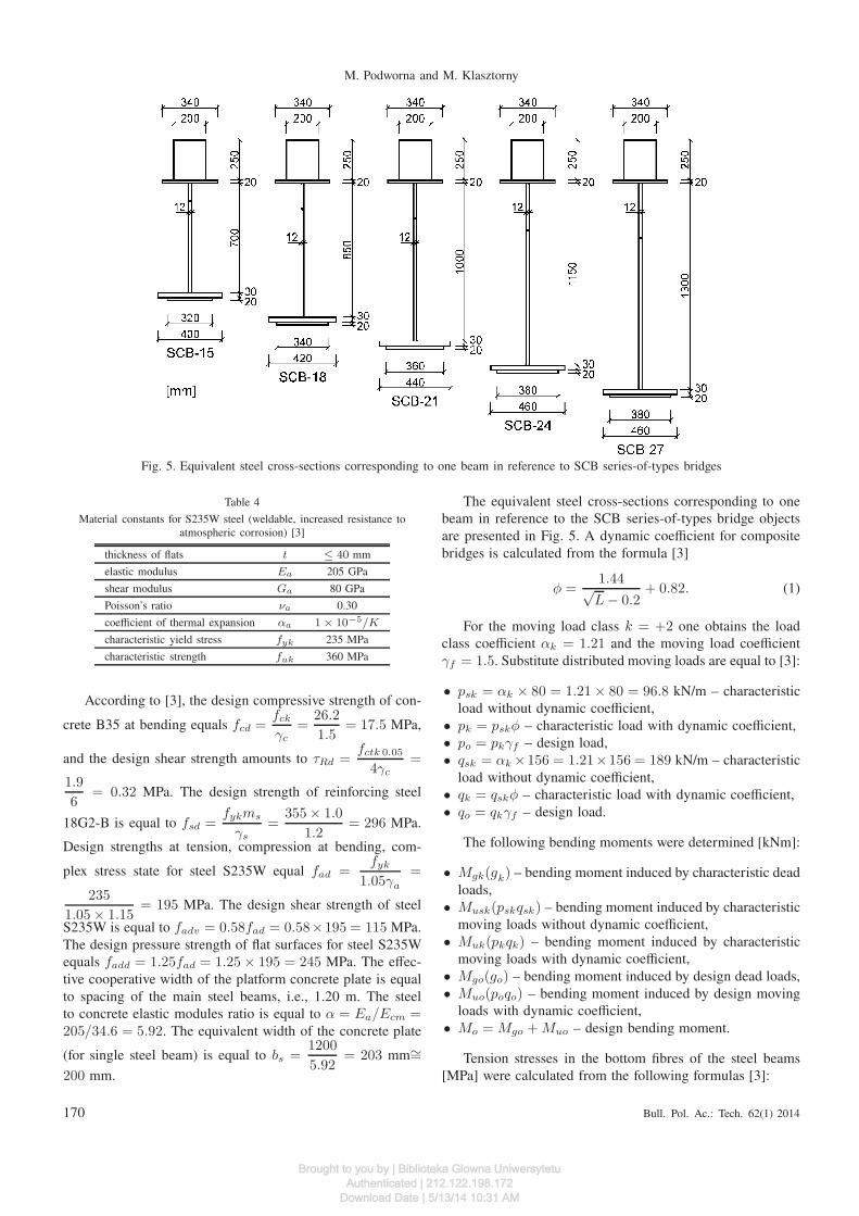
Fig. 5. Equivalent steel cross-sections corresponding to one beam in reference to SCB series-of-types bridges
Table 4
Material constants for S235W steel (weldable, increased resistance to
atmospheric corrosion) [3]
thickness of flats t ≤ 40 mm
elastic modulus Ea 205 GPa
shear modulus Ga 80 GPa
Poisson’s ratio νa 0.30
coefficient of thermal expansion αa 1 × 10⁻⁵/K
characteristic yield stress fyk 235 MPa
characteristic strength fuk 360 MPa
According to [3], the design compressive strength of con-
crete B35 at bending equals fcd =fck
γc
=26.2
1.5= 17.5 MPa,
and the design shear strength amounts to τRd =fctk 0.05
4γc
=
1.9
6= 0.32 MPa. The design strength of reinforcing steel
18G2-B is equal to fsd =fykms
γs
=355 × 1.0
1.2= 296 MPa.
Design strengths at tension, compression at bending, com-
plex stress state for steel S235W equal fad =fyk
1.05γa
=
235
1.05 × 1.15= 195 MPa. The design shear strength of steel
S235W is equal to fadv = 0.58fad = 0.58×195 = 115 MPa.
The design pressure strength of flat surfaces for steel S235W
equals fadd = 1.25fad = 1.25 × 195 = 245 MPa. The effec-
tive cooperative width of the platform concrete plate is equal
to spacing of the main steel beams, i.e., 1.20 m. The steel
to concrete elastic modules ratio is equal to α = Ea/Ecm =205/34.6 = 5.92. The equivalent width of the concrete plate
(for single steel beam) is equal to bs =1200
5.92= 203 mm∼=
200 mm.
The equivalent steel cross-sections corresponding to one
beam in reference to the SCB series-of-types bridge objects
are presented in Fig. 5. A dynamic coefficient for composite
bridges is calculated from the formula [3]
φ =1.44√L − 0.2
+ 0.82. (1)
For the moving load class k = +2 one obtains the load
class coefficient αk = 1.21 and the moving load coefficient
γf = 1.5. Substitute distributed moving loads are equal to [3]:
• psk = αk × 80 = 1.21 × 80 = 96.8 kN/m – characteristic
load without dynamic coefficient,
• pk = pskφ – characteristic load with dynamic coefficient,
• po = pkγf – design load,
• qsk = αk ×156 = 1.21×156 = 189 kN/m – characteristic
load without dynamic coefficient,
• qk = qskφ – characteristic load with dynamic coefficient,
• qo = qkγf – design load.
The following bending moments were determined [kNm]:
• Mgk(gk) – bending moment induced by characteristic dead
loads,
• Musk(pskqsk) – bending moment induced by characteristic
moving loads without dynamic coefficient,
• Muk(pkqk) – bending moment induced by characteristic
moving loads with dynamic coefficient,
• Mgo(go) – bending moment induced by design dead loads,
• Muo(poqo) – bending moment induced by design moving
loads with dynamic coefficient,
• Mo = Mgo + Muo – design bending moment.
Tension stresses in the bottom fibres of the steel beams
[MPa] were calculated from the following formulas [3]:
170 Bull. Pol. Ac.: Tech. 62(1) 2014
Brought to you by | Biblioteka Glowna UniwersytetuAuthenticated | 212.122.198.172
Download Date | 5/13/14 10:31 AM

Vertical vibrations of composite bridge/track structure/high-speed train systems. Part 1
• σak = 0.001(Muk + Mgk)/Wd – normal stresses induced
by characteristic moving load with dynamic coefficient and
characteristic dead load [MPa],
• σao =0.001Mo
Wd
+ σao,r – normal stresses induced by
design load [MPa] with rheological effects taken into con-
sideration (Wd [m3] is bending rate for bottom fibres)
Compression stresses in the top fibres of the RC platform
plate [MPa] were calculated according to the formulas [4]:
• σbk = 0.001(Muk+Mgk)/αWg – normal stresses induced
by characteristic moving load with dynamic coefficient and
by characteristic dead load [MPa],
• σbo =0.001Mo
αW g
+ σbo,r – normal stresses induced by de-
sign load [MPa] with rheological effects taken into consid-
eration (Wg [m3] is bending rate for top fibres).
Values of stresses induced by rheological effects σbo,r (con-
crete creep and shrinkage with creep taken into consideration)
were calculated based on the algorithms presented in [4].
According to design rules [3] the ultimate limit state con-
ditions in respect to longitudinal normal stresses take the form
σao(Mo) ≤ fad,
σbo(Mo) ≤ fcd.(2)
The limit state condition in respect to deflections has the form
w(Musk) ≤ wd, (3)
where wd = L/800 for v ≤ 160 km/h. The fatigue limit state
conditions are in the form
σak(MukMgk) ≤ 0.75fad,
σbk(MukMgk) ≤ 0.60fck.(4)
The limit state condition in respect to comfort (imposed on
deflections) is in the form
w(Muk) ≤ wpd(L), (5)
where wpd(L) = L/750 for v ≤ 200 km/h. The limit state
condition in respect to rail traffic safety (limitation of deflec-
tions under dead load) takes the form
wmin(L) ≤ w(Mgk) ≤ wmax(L) (6)
and values wmin(L), wmax(L) are given in [3].
Table 5 collects values of geometric, mass and stiffness pa-
rameters of SCB series-of-types bridges, approach slabs and
ballasted track, used in numerical modelling of the BTT sys-
tem. A composite cross-section of a bridge superstructure
was reduced to an equivalent steel cross-section. The para-
meters correspond to Figs. 1–5. Material data given in [1, 2]
have been applied. Table 5 includes the following quantities:
• F (0.5L) – area of equivalent cross-section of bridge su-
perstructure, at midspan,
• hb (0.5L), ht (0.5L) – vertical distances to bottom and
top fibres measured from mass centre of equivalent cross-
section of bridge superstructure, at midspan,
• I(0.5L) – geometrical moment of inertia in respect to hor-
izontal central axis of equivalent cross-section of bridge
superstructure, at midspan,
• Wb (0.5L), Wt (0.5L) – bending rates for bottom and top
fibres of equivalent cross-section of bridge superstructure,
at midspan,
• E = 205 GPa – Young’s modulus of S235W steel (material
of main beams),
• EI(0.5L) – flexural stiffness of equivalent cross-section of
bridge superstructure, at midspan,
• m(0.5L) – mass per unit length of equivalent cross-section
of bridge superstructure, at midspan (with isolation lay-
er, levelling concrete, kerbs, covers, sidewalk, joints, ribs,
brackets taken into account),
• F (0), hb (0), ht (0), I (0), Wb (0), Wt (0), EI (0), m(0)– geometric, stiffness and mass parameters of equiva-
lent cross-section of bridge superstructure, at support area
(without overlay of lower chord of main beams),
• γ – Rayleigh damping ratio of bridge superstructure,
• fl = 1 Hz, fu = 500 Hz – vibration frequency range in
which damping is approximately constant.
Table 5
Parameters of bridges forming SCB series-of-types
Parameter Unit SCB-15 SCB-18 SCB-21 SCB-24 SCB-27
L m 15.00 18.00 21.00 24.00 27.00
hb (0.5L) mm 735 858 1009 1156 1342
ht (0.5L) mm 441 518 617 720 834
I(0.5L) m4 0.067789 0.101580 0.154680 0.221439 0.311789
Wb (0.5L) m3 0.092242 0.118366 0.153232 0.191603 0.232258
Wt (0.5L) m3 0.153681 0.196170 0.250882 0.307435 0.374040
EI(0.5L) Nm2 13.897 × 10⁹ 20.824 × 10⁹ 31.710 × 10⁹ 45.395 × 10⁹ 63.917 × 10⁹
I (0) m4 0.050188 0.075905 0.116859 0.168889 0.240933
EI(0) Nm2 10.289 × 10⁹ 15.561 × 10⁹ 23.956 × 10⁹ 34.622 × 10⁹ 49.391 × 10⁹
m(0.5L) kg/m 5300 5470 5660 5850 6020
m(0) kg/m 5050 5210 5380 5550 5710
γ – 0.01125 0.0075 0.005 0.005 0.005
Bull. Pol. Ac.: Tech. 62(1) 2014 171
Brought to you by | Biblioteka Glowna UniwersytetuAuthenticated | 212.122.198.172
Download Date | 5/13/14 10:31 AM

M. Podworna and M. Klasztorny
Table 6
Values of bending moments in engineering calculations of bridges forming SCB series-of types
Parameter Unit SCB-15 SCB-18 SCB-21 SCB-24 SCB-27
Mgk kNm 3086.7 4353.8 6104.6 8184.1 10439.0
Musk kNm 4509.7 5981.5 7889.6 10030.0 12243.7
Muk kNm 5466.0 7035.4 9061.8 11298.3 13568.7
Mgo kNm 4240.3 5969.7 8352.9 11175.6 14228.8
Muo kNm 8199.0 10553.1 13592.7 16947.5 20353.0
Mo kNm 12439.3 16522.8 21945.5 28123.1 34581.9
Table 7
Values of stresses in engineering calculations of bridges forming SCB series-of types
Parameter Unit SCB-15 SCB-18 SCB-21 SCB-24 SCB-27
σao(Mo) MPa 134.86 139.59 143.22 146.78 148.89
σao,r MPa 5.36 5.19 5.10 5.04 5.20
σao MPa 140.22 144.78 148.32 151.82 154.09
fad MPa 195 195 195 195 195
σbo(Mo) MPa 13.66 14.22 14.76 15.44 15.60
σbo,r MPa −0.59 −0.74 −0.88 −1.00 −1.12
σbo MPa 13.07 13.48 13.88 14.44 14.48
fcd MPa 17.5 17.5 17.5 17.5 17.5
σak(Muk, Mgk) MPa 92.72 96.22 98.98 101.68 103.37
0.75fad MPa 146.3 146.3 146.3 146.3 146.3
σbk(Muk, Mgk) MPa 9.39 9.80 10.20 10.70 10.83
0.60fck MPa 15.7 15.7 15.7 15.7 15.7
σgk MPa 33.47 36.78 39.84 42.71 44.95
Table 8
Values of deflections in engineering calculations of bridges forming SCB series-of types
Parameter Unit SCB-15 SCB-18 SCB-21 SCB-24 SCB-27
w(Musk) mm 7.9 10.1 11.9 13.8 15.1
wd mm 18.8 22.5 26.3 30.0 33.8
w(Muk) mm 9.6 11.9 13.6 15.5 16.7
wpd mm 20.0 24.0 28.0 32.0 36.0
w(Mgk) mm 5.4 7.3 9.2 11.2 12.8
wmin mm 2.2 3.0 3.5 4.0 5.0
wmax mm 10.5 17.0 20.0 22.0 25.0
Subsequent physical parameters occurring in numerical
modelling of BTT systems have the following values [1, 2]:
ρb = 2000 kg/m3 – ballast density, mr, msr = 120 kg/m,
Mr, Msr = 72 kg/m, Ms = 366 kg, ms = 610 kg/m,
Mb = 2900 kg, mb = 4833 kg/m, ma = 2000 kg/m,
La = 4.80 m, 2D = 204 m where: mr, Mr – mass of main
rails per unit length and mass of main rails per one sleeper,
msr, Msr – mass of side rails per unit length and mass of
side rails per one sleeper, Ms, ms – mass of one sleeper and
two fasteners and mass of one sleeper and two fasteners per
unit length, Mb, mb – mass of ballast per one sleeper and
mass of ballast per unit length, ma – mass of approach slab
per unit length, La – length of approach slab, 2D – length of
out-of-approach zone.
The main results of engineering calculations of bridges
forming the SCB series-of-types, with parameters set up in Ta-
ble 5, are given in Tables 6, 7, 8, where σgk = 0.001Mgk/Wd
– normal stresses in bottom fibres of main steel beams induced
by characteristic dead load [MPa]. Design conditions (2-6) are
satisfied.
3. Shortened description of mathematical
modelling, numerical modelling
and simulation of BTT systems
The BTT system has the following inertial subsystems
(Figs. 6, 7) [1]: BS – bridge superstructure, LAS – left ap-
proach slab, RAS – right approach slab, LB – left ballast-bed,
RB – right ballast-bed, SL –sleepers, OR – operating rails, SR
–side rails, RVi, i = 1, 2, . . . , Nv – railway vehicles. These
subsystems are subject to the relevant subsets of vertical in-
teraction forces, carried by elastic/viscoelastic physically lin-
172 Bull. Pol. Ac.: Tech. 62(1) 2014
Brought to you by | Biblioteka Glowna UniwersytetuAuthenticated | 212.122.198.172
Download Date | 5/13/14 10:31 AM

Vertical vibrations of composite bridge/track structure/high-speed train systems. Part 1
ear/nonlinear constraints. Using Lagrange’s equations and the
internal assembling, linear matrix equations of motion of in-
dividual subsystems with the generalized load vectors stored
in an implicit form are obtained. Linear/non-linear interaction
forces are transformed into the generalized load vectors. This
formulation leads to equations of motion of the subsystems
with constant coefficients. Coupling and non-linearity of the
subsystems is hidden in the generalized load vectors expressed
in terms of the interaction forces. Detailed formulation in ref-
erence to mathematical modelling, numerical modelling and
simulation of BTT systems is presented in [1, 2]. Symbols
marked in Figs. 6–8 are defined in [1]
A 1D physical model of the track structure/bridge sub-
system is presented in Fig. 7. A constant sleeper spacing dis used to discretize the subsystem. The main rails are fixed
at the ends of the finite-long section of track 4D + Lo. The
side rails are of length of Lo and are rested viscoelastically
on the sleepers. Viscoelastic elements modelling the fasteners
and the ballast incorporate physically nonlinear elastic con-
straints. Discretization of beams modelling operating rails,
side rails, approach slabs and the bridge superstructure uses
finite elements deformed in flexure, with 4DOF and length d.
Nodes of the finite elements coincide with the positions of
the sleepers [1].
Fig. 6. Schematic diagram of BTT system at time t = 0 and t = T
Fig. 7. 1D physical model of track structure/bridge subsystem
Fig. 8. 1D physical model of bridge loaded with interaction forces carried by ballast
Bull. Pol. Ac.: Tech. 62(1) 2014 173
Brought to you by | Biblioteka Glowna UniwersytetuAuthenticated | 212.122.198.172
Download Date | 5/13/14 10:31 AM

M. Podworna and M. Klasztorny
Ballast mass on the approach slabs and on the bridge is
considered in the distributed form. Step-wise changes in the
parameters of the bridge superstructure occur in respective
nodes of the finite element mesh (Figs. 7, 8) [1]. The phys-
ical model of the track/bridge subsystem is symmetrical in
reference to the midspan.
Transient and quasi-steady-state vibrations of the BTT sys-
tem are governed by 8 + Nv matrix equations of motion in
the following implicit form [1]:
Bq̈ + Cq̇ + Kq = F
Blaq̈la+Claq̇la + Klaqla = Fla
Braq̈ra+Craq̇ra + Kraqra = Fra
{Mb} q̈lb = Flb
{Mb} q̈rb = Frb
{Ms} q̈s = Rf − Rb
Brq̈r + Crq̇r + Krqr = Fr
Bsrq̈sr + Csr q̇sr + Ksrqsr = Fsr
Biq̈i = Fi, i = 1, 2, . . . , Nv
(7)
where q (t), qla (t), qra (t), qlb (t), qrb (t), qs (t), qr (t),qsr (t) – vectors of generalised coordinates for BS, LAS,
RAS, LB, RB, SL, OR, SR subsystems, respectively, qi (t),i = 1, 2, . . . , Nv – vectors of generalised coordinates for sub-
sequent rail-vehicles, B, C, K – mass, damping and stiffness
matrices for BS subsystem, respectively, Bla, Cla, Kla, Bra,
Cra, Kra – mass, damping and stiffness matrices for LAS
and RAS subsystems, respectively, {Mb} – mass matrix for
LB and RB subsystems, {Ms} – mass matrix for SL sub-
system, Br, Cr, Kr, Bsr, Csr, Ksr – mass, damping and
stiffness matrices for OR and SR subsystems, respectively,
Bi – mass matrix for ith rail-vehicle, Rf , Rsf – vectors
of interaction forces transmitted by fasteners in OR and SR
subsystems, respectively, Rb – vector of interaction forces
transmitted by ballast-bed, Rg – vector of interaction forces
transmitted by track-bed, Rwi – vector of moving pressure
forces of ith vehicle wheel sets acting on rails, F (Rb) – gen-
eralised load vector in implicit form, related to BS subsystem,
Fla (Rb,Rg), Fra (Rb,Rg) – generalised load vectors in im-
plicit form, related to LAS and RAS subsystems, respectively,
Flb (Rb,Rg), Frb (Rb,Rg) – generalised load vectors in im-
plicit form, related to LB and RB subsystems, respectively,
Fr (Rf ,Rwi) , i= 1, 2, . . . ,Nv, Fsr (Rsf ) – generalised load
vectors in implicit form, related to OR and SR subsystems,
respectively, Ri= col (R1iR2i. . .R10,i) – vector of vertical
interactions transmitted by 1st and 2nd stage suspensions of
ith vehicle, G – generalised load vector reflecting static pres-
sures of wheel sets onto rails, Fi (Ri,G), i = 1, 2, . . . , Nv
– generalised load vector in implicit form, related to RVi,
i = 1, 2, . . . , Nv subsystem, ˙( ) = d/dt – differentiation with
respect to time variable t. Detailed formulae defining matrices
and vectors in Eq. (7) are given in [1].
Numerical investigations have been carried out for a Ger-
man passenger train ICE-3.The enhanced Matsuura model of
a rail-vehicle equipped with two two-axle bogies is applied.
Wheel sets of the vehicle are modelled as point masses vibrat-
ing vertically, each with 1DOF. Bogie frames are modelled as
rigid disks, each with 2DOF (vertical translation and rotation).
The car body is also modelled as a disk with 2DOF. Suspen-
sions of the first and second stage are linear viscoelastic. The
masses modelling the wheel sets are fitted with one-sided ver-
tical springs of nonlinear Hertzian contact stiffness reflecting
wheel set – rails contact. The detailed description of the rail-
vehicle modelling the reader can find in [1].
Based on Eq. (7) and remaining formulae presented in [1],
the authors developed a computer programme in Delphi for
simulation of dynamic processes in BTT systems.
4. Traffic safety and passenger comfort
conditions
A dynamic response of a bridge due to a high-speed train
is usually described by means of dynamic amplification fac-
tors, bridge deck accelerations and vehicle body accelerations.
Dynamic amplification factors concern the main output quan-
tities for the bridge superstructure, i.e. the vertical deflection
and the longitudinal normal stress in the bottom fibres of the
main beams, at the midspan.
Railway bridges loaded by high-speed trains need to be
designed or modernized to ensure the traffic safety condi-
tion (TSC) and the passenger comfort condition (PCC). UIC
(Draft) Code 776-2, “Design requirements for rail bridges
based on interaction phenomena between train, track, bridge
and in particular speed”, Paris, France, Union Int. des
Chemins de Fer, 2003 specifies the following conditions [5]:
• the TSC expressed by the limit vertical acceleration of the
bridge deck:
ap,lim = 0.35g = 3.43 m/s2,
• the PCC expressed by the limit vertical deflection of the
bridge span:
wlim = L/1700, where L is the bridge span length.
The limits of deformation and vibration to be taken into
account for the design of new railway bridges are specified in
EN 1990 Eurocode: “Basis of structural design, Annex A2:
Application for bridges”. Excessive bridge deformations can
endanger railway traffic by creating unacceptable changes in
vertical and horizontal track geometry and excessive stresses
in rails. Excessive vibrations can lead to ballast instability and
unacceptable reduction in wheel – rail contact forces. Exces-
sive deformations can also affect the loads imposed on the
track/bridge system and create conditions which cause pas-
senger discomfort.
The basic verifications on bridge deformations, performed
for TSC condition, are as follows (EN 1990 Eurocode: “Basis
of structural design, Annex A2: Application for bridges, EN
1991-2 Eurocode 1: Actions on structures, Part 2: General
actions – traffic loads on bridges”):
174 Bull. Pol. Ac.: Tech. 62(1) 2014
Brought to you by | Biblioteka Glowna UniwersytetuAuthenticated | 212.122.198.172
Download Date | 5/13/14 10:31 AM

Vertical vibrations of composite bridge/track structure/high-speed train systems. Part 1
• maximum peak vertical acceleration of the deck due to rail
traffic actions (to avoid ballast instability and unacceptable
reduction in wheel/rail contact forces),
• vertical deflection of the deck throughout each span (to
ensure acceptable vertical track radii and generally robust
structures).
The limit value of bridge deck acceleration calculated
along the line of a track shall not exceed the design value
ap,lim = 3.50 m/s2 for ballasted track. The maximum to-
tal vertical deflection of the bridge structure loaded with the
classified characteristic vertical loading (not for Real Trains),
measured along any track, should not exceed L/600.
Verification on bridge deformations, performed for PCC
condition, can be related to vertical deflection of the deck
or directly to the carbody vertical acceleration. The indica-
tive levels of comfort, expressed by the vertical acceleration
ab,max inside the carriage during the travel are specified in
Table 9 (EN 1990 Eurocode).
Table 9
The indicative levels of passenger comfort
Level of comfort ab,lim [m/s2]
very good 1.0
good 1.3
acceptable 2.0
5. Prediction of forced resonances
The BTT system under consideration is weakly nonlinear
physically (ballast, rail fastenings) and maps geometrically
infinite track approximately via out-of-approach zones of the
track. Based on preliminary simulations, it is concluded that
the BT (bridge/track structure) subsystem exhibits modal char-
acteristics similar to those for a linear system. Fundamental
modal characteristics of the BT subsystem, called quasi-free
damped vibrations, quasinatural frequency can be identified
after passage of the high-speed train over the bridge (when
the train is in the right out-of-approach zone of the track).
Preliminary calculations identifying the fundamental nat-
ural quasi-frequency of the physically nonlinear bridge/track
structure subsystem are performed for a selected operating
speed, e.g., v = 250 km/h. Six last nodes on the chart of
quasi-free damped vibrations induced by the passage of the
train are identified. Approximate values of the fundamental
natural quasi-period and quasi-frequency of the bridge/track
subsystem are calculated from the formulae
T1 =s
v, f1 =
1
T1
, (8)
where s – distance of the load head over one cycle of free
damped vibrations (average value corresponding to above not-
ed six last nodes). Periods of subsequent harmonics of the
quasi-static excitation of the bridge/track subsystem are
T̄i =l
iv, i = 1, 2, . . . . (9)
A prediction of the resonant operating speeds, corresponding
to equality of the fundamental natural quasi-period and sub-
sequent harmonics of the quasi-static excitation, is as follows
T1 = T i ⇒ T1 =l
iv⇒ vi1 =
l
iT1
, i = 1, 2, . . . , (10)
where the total length of the vehicle equals l = 24.78 m.
Due to parametric effects resulting from quasi unsprung
moving masses (wheel sets), the more exact resonant oper-
ating speeds are lower by ∼1.5% compared to the values
calculated from Eq. (10). This phenomenon was detected
based on preliminary simulations of dynamic processes in
BTT systems. Predicted resonant operating speeds decreased
by ∼1.5% are collected in Table 10.
Table 10
Predicted resonant operating speeds
Bridge codeT1 f1 Resonant operating speed [km/h]
[s] [1/s] v11 v21 v31 v41 v51
SCB-15 0.163 6.14 540 270 180 135 108
SCB-18 0.195 5.14 450 225 149 112 90
SCB-21 0.216 4.62 407 203 135 101 82
SCB-24 0.238 4.20 370 185 123 93 74
SCB-27 0.256 3.90 343 171 114 86 69
6. Representative results of numerical tests
for bridges forming SCB series-of-types
The following output quantities are defined (see Fig. 6):
• w(0.5Lt) – deflection of bridge superstructure at midspan
[mm],
• σ(0.5Lt) – longitudinal normal stress in bottom fibres of
main beams, at midspan [MPa],
• ap(0.5Lt) – vertical acceleration of RC platform, at
midspan [m/s2],
• R1,7(t) – selected dynamic pressure force of wheel set onto
rails (1st wheel set of 7th vehicle) [kN],
• ab7f(t) – selected vertical acceleration of carbody (pivot
over front bogie of 7th vehicle) [m/s2].
The following design quantities are defined:
wmax = maxt
w (0.5L, t) [mm],
σmax = maxt
σ (0.5L, t) [MPa],
ap,max = maxt
|ap (0.5L, t) | [m/s2],
Rmin=mint{Rki(t), k = 1, 2, 3, 4, i = 1, 2, . . . , Nv} [kN],
ab,max=maxt
{|abiα(t)|, i = 1, 2, . . . , Nv, α = fr [m/s2],
(11)
where Rki (t), k = 1, 2, 3, 4, i = 1, 2, . . . , Nv – dynamic
pressure forces of wheel sets onto rails [kN], abiα (t) i =1, 2, . . . , Nv, α = f, r – vertical accelerations of carbodies
over front (f) and rear (r) bogie [m/s2].
In reference to the SCB-15 bridge, the simulations were
conducted for the ICE-3 train moving at the most dangerous
resonant operating velocities , i.e. v31 = 180 km/h (resonance
Bull. Pol. Ac.: Tech. 62(1) 2014 175
Brought to you by | Biblioteka Glowna UniwersytetuAuthenticated | 212.122.198.172
Download Date | 5/13/14 10:31 AM

M. Podworna and M. Klasztorny
of first quasi-modal system with third harmonic component of
static periodic moving load), v21 = 270 km/h (resonance of
first quasi-modal system with second harmonic component of
the static periodic moving load) and at the maximum operat-
ing velocity vmax = 300 km/h. Analogous simulations were
conducted for the remaining bridges forming the SCB type-
of-series. Values of the design quantities for bridges SCB-15,
SCB-18, SCB-21, SCB-24, SCB-27 are given in Table 11.
The values are compared with those ones for the quasi-static
motion of the train (v = 30 km/h). Figures 9–13 present
time-histories of selected output quantities for the resonant
service velocities v31 for SCB-15, SCB-18, SCB-21, SCB-
24, SCB-27, respectively. Time-histories of dynamic process-
es are reflected with thin lines (v = v31) and are presented
against a background of time-histories of quasi-static process-
es (v = 30 km/h) with thick lines.
Table 11
Values of design quantities for bridges forming SCB series-of-types
Bridge Operating velocity v [km/h] wmax [mm] σmax [MPa] ap,max [m/s2] Rmin [kN] ab,max [m/s2]
SCB-15
v = 30 km/h 2.20 13.00 0.02 156.4 0.03
v21 = 270 km/h 5.82 38.25 6.12 136.5 0.22
v31 = 180 km/h 6.74 43.29 7.44 141.4 0.24
vmax = 300 km/h 4.37 27.18 3.75 138.7 0.12
SCB-18
v = 30 km/h 2.88 14.13 0.01 156.3 0.03
v21 = 225 km/h 2.89 15.24 0.92 145.7 0.13
v31 = 149 km/h 5.80 29.42 2.99 150.6 0.19
vmax = 300 km/h 5.28 26.61 2.60 140.6 0.18
SCB-21
v = 30 km/h 3.22 14.01 0.01 156.3 0.02
v21 = 203 km/h 5.38 24.32 1.94 150.4 0.21
v31 = 135 km/h 3.79 17.17 0.78 154.6 0.11
vmax = 300 km/h 5.87 26.00 2.59 141.4 0.19
SCB-24
v = 30 km/h 3.51 13.67 0.01 156.3 0.02
v21 = 185 km/h 6.41 25.61 2.10 151.9 0.27
v31 = 123 km/h 6.47 25.92 2.20 149.9 0.30
vmax = 300 km/h 7.09 27.88 2.62 143.7 0.28
SCB-27
v = 30 km/h 3.66 13.31 0.02 156.4 0.02
v21 = 171 km/h 5.65 20.78 1.25 153.2 0.25
v31 = 114 km/h 5.13 19.05 1.02 153.0 0.22
vmax = 300 km/h 7.74 28.16 2.65 145.5 0.30
Fig. 9. SCB-15 bridge. Normal stress σ (0.5L, t) [MPa] for resonant service velocity v31 = 180 km/h (thin line) against a background of
quasi-static process (thick line)
176 Bull. Pol. Ac.: Tech. 62(1) 2014
Brought to you by | Biblioteka Glowna UniwersytetuAuthenticated | 212.122.198.172
Download Date | 5/13/14 10:31 AM

Vertical vibrations of composite bridge/track structure/high-speed train systems. Part 1
Fig. 10. SCB-18 bridge. Normal stress σ (0.5L, t) [MPa] for resonant service velocity v31 = 149 km/h (thin line) against background of
quasi-static process (thick line)
Fig. 11. SCB-21 bridge. Normal stress σ (0.5L, t) [MPa] for resonant service velocity v31 = 203 km/h (thin line) against background of
quasi-static process (thick line)
Based on Table 11 and Figs. 9–13, the following detailed
conclusions are formulated.
1. Values of the dynamic amplification factor in displacement
for subsequent bridges, corresponding to an ICE-3 train
moving on an even track, differ from each other. At res-
onant operating velocities, this factor takes the maximum
value 3.06 for the shortest bridge SCB-15. At the maximum
operating speed, this factor takes the maximum value 2.11
for the longest bridge SCB-27. Some resonant velocities,
for SCB-18 and SCB-21 bridges, did not induce resonance
amplification effect. The limit state in deflection, expressed
by the condition wmax ≤ wlim = L/1700, is satisfied for
all objects forming the SCB series-of-types, loaded by an
ICE-3 high-speed train moving at operating speeds 100–
300 km/h.
2. Values of the dynamic amplification factor in stress for sub-
sequent bridges, corresponding to an ICE-3 train moving
on an even track, also differ from each other. At resonant
operating velocities, this factor takes the maximum value
3.33 for the shortest bridge SCB-15. At the maximum op-
erating speed, this factor takes the maximum value 2.12 for
the longest bridge SCB-27. Some resonant velocities, for
SCB-18 and SCB-21 bridges, did not induce resonance am-
plification effect. The fatigue limit state formulated accord-
ing to [6] is satisfied with safety margin ∼1.50 for all ob-
jects forming the SCB series-of-types, loaded by an ICE-3
high-speed train moving at operating speeds 100–300 km/h.
3. The limit state of rail traffic safety is satisfied for bridges
SCB-18, SCB-21, SCB-24 and SCB-27. For bridge SCB-
15 the condition ap,max ≤ ap,lim = 3.50 m/s2 is exceeded
about two times at resonant operating speeds and weakly
Bull. Pol. Ac.: Tech. 62(1) 2014 177
Brought to you by | Biblioteka Glowna UniwersytetuAuthenticated | 212.122.198.172
Download Date | 5/13/14 10:31 AM

M. Podworna and M. Klasztorny
Fig. 12. SCB-24 bridge. Normal stress σ (0.5L, t) [MPa] for resonant service velocity v31 = 185 km/h (thin line) against background of
quasi-static process (thick line)
Fig. 13. SCB-27 bridge. Normal stress σ (0.5L, t) [MPa] for resonant service velocity v31 = 171 km/h (thin line) against background of
quasi-static process (thick line)
satisfied for the maximum operating speed. Thus, these
speeds should be omitted for the shortest bridge span
L = 15 m.
4. The extreme drop in dynamic pressures of ICE-3 train
wheel sets is observed for SCB-15 bridge at the resonant
operating speed v21 = 270 km/h and is equal to 87% of the
static pressure force. This drop does not exceed the limit
value 75% [6]. Reduction in wheel/rail contact forces is
acceptable for all objects forming the SCB series-of-types,
loaded by an ICE-3 high-speed train moving at operating
speeds 100–300 km/h.
5. The limit state of comfort expressed by the condition
ab,max ≤ ab,lim is satisfied on a very good level (see
Table 9) for all objects forming the SCB series-of-types,
loaded by an ICE-3 train moving at operating speeds 100–
300 km/h.
7. Conclusions
1. The limit state in deflection, expressed by the condition
wmax ≤ wlim = L/1700, is satisfied for all objects form-
ing the SCB series-of-types, loaded by an ICE-3 high-speed
train moving at operating speeds 100–300 km/h.
2. The fatigue limit state is satisfied with safety margin ∼1.50
for all objects forming the SCB series-of-types, loaded by
an ICE-3 high-speed train moving at operating speeds 100–
300 km/h.
3. The limit state of rail traffic safety is satisfied for bridges
SCB-18, SCB-21, SCB-24 and SCB-27. For bridge SCB-
15 the condition ap,max ≤ ap,lim = 3.50 m/s2 is exceeded
about two times at resonant operating speeds and weakly
satisfied for the maximum operating speed. These speeds
should be omitted for the shortest bridge span L = 15 m.
178 Bull. Pol. Ac.: Tech. 62(1) 2014
Brought to you by | Biblioteka Glowna UniwersytetuAuthenticated | 212.122.198.172
Download Date | 5/13/14 10:31 AM

Vertical vibrations of composite bridge/track structure/high-speed train systems. Part 1
4. The extreme drop in dynamic pressures of ICE-3 train
wheel sets is observed for SCB-15 bridge at the resonant
operating speed v21 = 270 km/h and is equal to 87% of
the static pressure force. This drop does not exceed the
limit value 75%. Reduction in wheel/rail contact forces is
acceptable for all objects forming the SCB series-of-types,
loaded by an ICE-3 high-speed train moving at operating
speeds 100–300 km/h.
5. The limit state of comfort expressed by the condition
ab,max ≤ ab,lim is satisfied on a very good level (ab,lim =1 m/s2) for all objects forming the SCB series-of-types,
loaded by an ICE-3 high-speed train moving at operating
speeds 100–300 km/h.
6. Dynamic phenomena in composite bridge/ballasted
track structure/high-speed train systems require ex-
perimental investigations focussed on their identifica-
tion/validation/verification. Such investigations are diffi-
cult, time-consuming and expensive; they may be per-
formed by an international research team.
Acknowledgements. The study is supported by the Nation-
al Centre for Science, Poland, as a part of the project No.
N N506 0992 40, realized in the period 2011–2013. This
support is gratefully acknowledged. The authors express many
thanks to Prof. Cz. Machelski for his support to calculations
of rheological stresses.
REFERENCES
[1] M. Podworna and M. Klasztorny, “Vertical vibrations of com-
posite bridge / track structure / high-speed train system. Part 2:
Physical and mathematical modelling”, Bull. Pol. Ac.: Tech. 62
(1), 181–196 (2014).
[2] M. Podworna, M. Klasztorny, “Vertical vibrations of composite
bridge / track structure / high-speed train system. Part 3: De-
terministic and random vibrations of exemplary system”, Bull.
Pol. Ac.: Tech. 62 (2), (2014), (to be published).
[3] J. Karlikowski, A. Madaj, and W. Wołowicki, Composite steel
– Concrete Bridge Structures, WKL Press, Warsaw, 2007, (in
Polish).
[4] C. Machelski, Modelling of Bridge Compression, DWE Press,
Wroclaw, 2010, (in Polish).
[5] M.-K. Song, H.-C. Noh, and C.-K. Choi, “A new three dimen-
sional finite element analysis model of high-speed train – bridge
interactions”, Engineering Structures 25, 1611–1626 (2003).
[6] M. Klasztorny, Dynamics of Beam Bridges under High-speed
Trains, WNT Press, Warsaw, 2005, (in Polish).
Bull. Pol. Ac.: Tech. 62(1) 2014 179
Brought to you by | Biblioteka Glowna UniwersytetuAuthenticated | 212.122.198.172
Download Date | 5/13/14 10:31 AM