vertical low-pressure pumpetanorm v - ksb
TRANSCRIPT
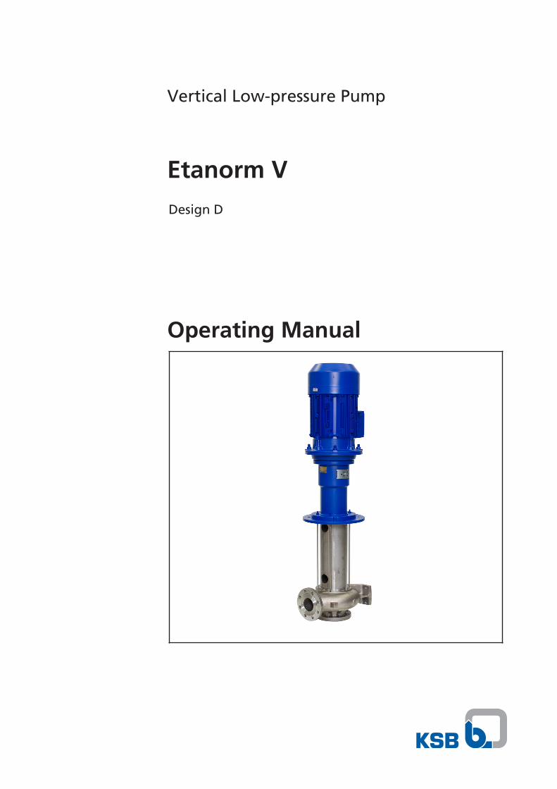
Vertical Low-pressure Pump
Etanorm VDesign D
Operating Manual

Legal information/Copyright
Operating Manual Etanorm V
Original operating manual
All rights reserved. The contents provided herein must neither be distributed, copied, reproduced,edited or processed for any other purpose, nor otherwise transmitted, published or made available to athird party without the manufacturer's express written consent.
Subject to technical modification without prior notice.
© KSB SE & Co. KGaA, Frankenthal 18/10/2019

Contents
3 of 52Etanorm V
Contents
Glossary .................................................................................................................................................. 5
1 General.................................................................................................................................................... 61.1 Principles ........................................................................................................................................................... 61.2 Installation of partly completed machinery.................................................................................................... 61.3 Target group..................................................................................................................................................... 61.4 Other applicable documents............................................................................................................................ 61.5 Symbols ............................................................................................................................................................. 6
2 Safety...................................................................................................................................................... 82.1 Key to safety symbols/markings....................................................................................................................... 82.2 General.............................................................................................................................................................. 82.3 Intended use ..................................................................................................................................................... 82.4 Personnel qualification and training............................................................................................................... 92.5 Consequences and risks caused by non-compliance with this manual ......................................................... 92.6 Safety awareness .............................................................................................................................................. 92.7 Safety information for the operator/user ....................................................................................................... 92.8 Safety information for maintenance, inspection and installation .............................................................. 102.9 Unauthorised modes of operation................................................................................................................ 10
3 Transport/Temporary Storage/Disposal............................................................................................. 113.1 Checking the condition upon delivery .......................................................................................................... 113.2 Transport......................................................................................................................................................... 113.3 Storage/preservation...................................................................................................................................... 123.4 Return to supplier........................................................................................................................................... 123.5 Disposal ........................................................................................................................................................... 13
4 Description of the Pump (Set) ............................................................................................................. 144.1 General description ........................................................................................................................................ 144.2 Designation..................................................................................................................................................... 144.3 Name plate...................................................................................................................................................... 154.4 Design details.................................................................................................................................................. 164.5 Configuration and function........................................................................................................................... 174.6 Noise characteristics ....................................................................................................................................... 184.7 Scope of supply............................................................................................................................................... 184.8 Pump size / shaft unit combinations ............................................................................................................. 194.9 Dimensions and weights ................................................................................................................................ 20
5 Installation at Site ................................................................................................................................ 215.1 Safety regulations........................................................................................................................................... 215.2 Checks to be carried out prior to installation............................................................................................... 215.3 Installing the pump set .................................................................................................................................. 215.4 Piping .............................................................................................................................................................. 24
5.4.1 Connecting the piping....................................................................................................................... 245.4.2 Permissible forces and moments at the pump nozzles.................................................................... 25
5.5 Electrical connection ...................................................................................................................................... 265.5.1 Setting the time relay ........................................................................................................................ 265.5.2 Connecting the motor ....................................................................................................................... 27
5.6 Checking the direction of rotation................................................................................................................ 27
6 Commissioning/Start-up/Shutdown................................................................................................... 286.1 Commissioning/Start-up................................................................................................................................. 28
6.1.1 Prerequisites for commissioning/start-up ......................................................................................... 286.1.2 Shaft seal ............................................................................................................................................ 286.1.3 Priming and venting the pump......................................................................................................... 286.1.4 Start-up............................................................................................................................................... 296.1.5 Shutdown ........................................................................................................................................... 29

Contents
4 of 52 Etanorm V
6.2 Operating limits.............................................................................................................................................. 296.2.1 Ambient temperature........................................................................................................................ 306.2.2 Frequency of starts............................................................................................................................. 306.2.3 Fluid handled ..................................................................................................................................... 30
6.3 Shutdown/storage/preservation .................................................................................................................... 316.3.1 Measures to be taken for shutdown ................................................................................................ 31
6.4 Returning to service ....................................................................................................................................... 316.5 Cleaning the pump set ................................................................................................................................... 32
7 Servicing/Maintenance........................................................................................................................ 337.1 Safety regulations........................................................................................................................................... 337.2 Servicing/Inspection........................................................................................................................................ 33
7.2.1 Supervision of operation ................................................................................................................... 337.2.2 Inspection work.................................................................................................................................. 34
7.3 Lubrication and lubricant change of rolling element bearings .................................................................. 357.3.1 Grease lubrication.............................................................................................................................. 35
7.4 Drainage/cleaning .......................................................................................................................................... 367.5 Dismantling the pump set.............................................................................................................................. 36
7.5.1 General information/Safety regulations........................................................................................... 367.5.2 Preparing the pump set..................................................................................................................... 377.5.3 Removing the complete pump set from the piping ........................................................................ 377.5.4 Removing the motor.......................................................................................................................... 387.5.5 Removing the riser............................................................................................................................. 387.5.6 Removing the volute casing and support column ........................................................................... 387.5.7 Removing the bearing lantern with shaft........................................................................................ 39
7.6 Reassembling the pump set ........................................................................................................................... 397.6.1 General information/Safety regulations........................................................................................... 397.6.2 Fitting the bearing lantern with shaft.............................................................................................. 407.6.3 Installing the volute casing and support column............................................................................. 417.6.4 Installing the riser .............................................................................................................................. 417.6.5 Mounting the motor.......................................................................................................................... 42
7.7 Tightening torques......................................................................................................................................... 427.7.1 Tightening torques for the pump..................................................................................................... 42
7.8 Spare parts stock............................................................................................................................................. 437.8.1 Ordering spare parts.......................................................................................................................... 437.8.2 Recommended spare parts stock for 2 years' operation to DIN 24296 .......................................... 437.8.3 Sets of spare parts.............................................................................................................................. 43
8 Trouble-shooting.................................................................................................................................. 45
9 Related Documents .............................................................................................................................. 469.1 General assembly drawings with list of components................................................................................... 46
9.1.1 General assembly drawing with list of components for D design .................................................. 46
10 EU Declaration of Conformity ............................................................................................................. 49
11 Certificate of Decontamination........................................................................................................... 50
Index ..................................................................................................................................................... 51
Glossary
5 of 52Etanorm V
1228
.81/
04-E
N
Glossary
Certificate of decontaminationA certificate of decontamination is enclosed by thecustomer when returning the product to themanufacturer to certify that the product has beenproperly drained to eliminate any environmentaland health hazards arising from components incontact with the fluid handled.
Discharge lineThe pipeline which is connected to the dischargenozzle
Hydraulic systemThe part of the pump in which the kinetic energyis converted into pressure energy
PumpMachine without drive, additional components oraccessories
Pump setComplete pump set consisting of pump, drive,additional components and accessories
Suction lift line/suction head lineThe pipeline which is connected to the suctionnozzle
1 General
6 of 52 Etanorm V
1228
.81/
04-E
N
1 General
1.1 PrinciplesThis operating manual is valid for the type series and variants indicated on the frontcover.
The operating manual describes the proper and safe use of this equipment in allphases of operation.
The name plate indicates the type series and size, the main operating data, the ordernumber and the order item number. The order number and order item numberclearly identify the pump set and serve as identification for all further businessprocesses.
In the event of damage, immediately contact your nearest KSB service facility tomaintain the right to claim under warranty.
1.2 Installation of partly completed machineryTo install partly completed machinery supplied by KSB refer to the sub-sections underServicing/Maintenance.
1.3 Target groupThis operating manual is aimed at the target group of trained and qualified specialisttechnical personnel. (ð Section 2.4, Page 9)
1.4 Other applicable documents
Table 1: Overview of other applicable documents
Document Contents
Data sheet Description of the technical data of the pump (set)
Installation plan/dimensionaldrawing
Description of mating and installation dimensionsfor the pump (set), weights
Drawing of auxiliary connections Description of auxiliary connections
Hydraulic characteristic curve Characteristic curves showing head, NPSHrequired, efficiency and power input
General drawing1) Sectional drawing of the pump
Sub-supplier product literature1) Operating manuals and other product literaturedescribing accessories and integrated machinerycomponents
Spare parts lists1) Description of spare parts
Piping layout1) Description of auxiliary piping
List of components1) Description of all pump components
Drawing for assembly1) Sectional drawing of the installed shaft seal
For accessories and/or integrated machinery components observe the relevantmanufacturer's product literature.
1.5 Symbols
Table 2: Symbols used in this manual
Symbol Description
✓ Conditions which need to be fulfilled before proceeding with thestep-by-step instructions
⊳ Safety instructions
⇨ Result of an action
⇨ Cross-references
1) If agreed upon in scope of supply
1 General
7 of 52Etanorm V
1228
.81/
04-E
N
Symbol Description
1.
2.
Step-by-step instructions
NoteRecommendations and important information on how to handlethe product

2 Safety
8 of 52 Etanorm V
1228
.81/
04-E
N
2 Safety
! DANGER All the information contained in this section refers to hazardous situations.
In addition to the present general safety information the action-related safetyinformation given in the other sections must be observed.
2.1 Key to safety symbols/markings
Table 3: Definition of safety symbols/markings
Symbol Description
! DANGER DANGER This signal word indicates a high-risk hazard which, if not avoided,will result in death or serious injury.
! WARNING WARNING This signal word indicates a medium-risk hazard which, if notavoided, could result in death or serious injury.
CAUTION CAUTION This signal word indicates a hazard which, if not avoided, couldresult in damage to the machine and its functions.
General hazard In conjunction with one of the signal words this symbol indicates ahazard which will or could result in death or serious injury.
Electrical hazard In conjunction with one of the signal words this symbol indicates ahazard involving electrical voltage and identifies information aboutprotection against electrical voltage.
Machine damage In conjunction with the signal word CAUTION this symbol indicatesa hazard for the machine and its functions.
2.2 General▪ This operating manual contains general installation, operating and maintenance
instructions that must be observed to ensure safe operation of the system andprevent personal injury and damage to property.
▪ Comply with all the safety instructions given in the individual sections of thisoperating manual.
▪ The operating manual must be read and understood by the responsible specialistpersonnel/operators prior to installation and commissioning.
▪ The contents of this operating manual must be available to the specialistpersonnel at the site at all times.
▪ Information and markings attached directly to the product must always becomplied with and kept in a perfectly legible condition at all times. This appliesto, for example:
– Arrow indicating the direction of rotation
– Markings for connections
– Name plate
▪ The operator is responsible for ensuring compliance with all local regulations nottaken into account.
2.3 Intended use▪ The product must not be used in potentially explosive atmospheres.
▪ The pump (set) must only be operated in the fields of application and within theuse limits specified in the other applicable documents. (ð Section 1.4, Page 6)
▪ Only operate pumps/pump sets which are in perfect technical condition.
▪ Do not operate the pump (set) in partially assembled condition.
2 Safety
9 of 52Etanorm V
1228
.81/
04-E
N
▪ Only use the pump to handle the fluids described in the data sheet or productliterature of the pump model or variant.
▪ Never operate the pump without the fluid to be handled.
▪ Observe the minimum flow rates indicated in the data sheet or product literature(to prevent overheating, bearing damage, etc).
▪ Observe the minimum flow rate and maximum flow rate indicated in the datasheet or product literature (to prevent overheating, mechanical seal damage,cavitation damage, bearing damage, etc.).
▪ Do not throttle the flow rate on the suction side of the pump (to preventcavitation damage).
▪ Consult the manufacturer about any use or mode of operation not described inthe data sheet or product literature.
2.4 Personnel qualification and trainingAll personnel involved must be fully qualified to transport, install, operate, maintainand inspect the machinery this manual refers to.
The responsibilities, competence and supervision of all personnel involved intransport, installation, operation, maintenance and inspection must be clearlydefined by the operator.
Deficits in knowledge must be rectified by means of training and instructionprovided by sufficiently trained specialist personnel. If required, the operator cancommission the manufacturer/supplier to train the personnel.
Training on the pump (set) must always be supervised by technical specialistpersonnel.
2.5 Consequences and risks caused by non-compliance with this manual▪ Non-compliance with these operating instructions will lead to forfeiture of
warranty cover and of any and all rights to claims for damages.
▪ Non-compliance can, for example, have the following consequences:
– Hazards to persons due to electrical, thermal, mechanical and chemicaleffects and explosions
– Failure of important product functions
– Failure of prescribed maintenance and servicing practices
– Hazard to the environment due to leakage of hazardous substances
2.6 Safety awarenessIn addition to the safety information contained in this operating manual and theintended use, the following safety regulations shall be complied with:
▪ Accident prevention, health regulations and safety regulations
▪ Explosion protection regulations
▪ Safety regulations for handling hazardous substances
▪ Applicable standards, directives and laws
2.7 Safety information for the operator/user▪ Fit protective equipment (e.g. contact guards) supplied by the operator for hot,
cold or moving parts, and check that the equipment functions properly.
▪ Do not remove any protective equipment (e.g. contact guards) during operation.
▪ Provide the personnel with protective equipment and make sure it is used.

2 Safety
10 of 52 Etanorm V
1228
.81/
04-E
N
▪ Contain leakages (e.g. at the shaft seal) of hazardous fluids handled (e.g.explosive, toxic, hot) so as to avoid any danger to persons and the environment.Adhere to all relevant laws.
▪ Eliminate all electrical hazards. (In this respect refer to the applicable nationalsafety regulations and/or regulations issued by the local energy supplycompanies.)
▪ If shutting down the pump does not increase potential risk, fit an emergency-stop control device in the immediate vicinity of the pump (set) during pump setinstallation.
2.8 Safety information for maintenance, inspection and installation▪ Modifications or alterations of the pump (set) are only permitted with the
manufacturer's prior consent.
▪ Use only original spare parts or parts/components authorised by themanufacturer. The use of other parts/components can invalidate any liability ofthe manufacturer for resulting damage.
▪ The operator ensures that maintenance, inspection and installation areperformed by authorised, qualified specialist personnel who are thoroughlyfamiliar with the manual.
▪ Only carry out work on the pump (set) during standstill of the pump.
▪ Only perform work on the pump set when it has been disconnected from thepower supply (de-energised).
▪ The pump (set) must have cooled down to ambient temperature.
▪ Pump pressure must have been released and the pump must have been drained.
▪ When taking the pump set out of service always adhere to the proceduredescribed in the manual. (ð Section 6.3, Page 31)
▪ Decontaminate pumps which handle fluids posing a health hazard.(ð Section 7.4, Page 36)
▪ As soon as the work has been completed, re-install and re-activate any safety-relevant devices and protective devices. Before returning the product to service,observe all instructions on commissioning. (ð Section 6.1, Page 28)
2.9 Unauthorised modes of operationNever operate the pump (set) outside the limits stated in the data sheet and in thismanual.
The warranty relating to the operating reliability and safety of the supplied pump(set) is only valid if the equipment is used in accordance with its intended use. (ð Section 2.3, Page 8)
3 Transport/Temporary Storage/Disposal
11 of 52Etanorm V
1228
.81/
04-E
N
3 Transport/Temporary Storage/Disposal
3.1 Checking the condition upon delivery1. On transfer of goods, check each packaging unit for damage.
2. In the event of in-transit damage, assess the exact damage, document it andnotify KSB or the supplying dealer and the insurer about the damage in writingimmediately.
3.2 Transport
DANGER
The pump (set) could slip out of the suspension arrangement
Danger to life from falling parts!
▷ Always transport the pump (set) in the specified position.
▷ Never attach the suspension arrangement to the free shaft end or the motoreyebolt.
▷ Observe the information about weights, centre of gravity and fastening points.
▷ Observe the applicable local accident prevention regulations.
▷ Use suitable, permitted lifting accessories, e.g. self-tightening lifting tongs.
CAUTION
Incorrect transport of the pump set
Damage to the tie bolts.
▷ Do not attach any ropes in the area of the tie bolts 905.
▷ Do not place or support the pump set on tie bolts 905.
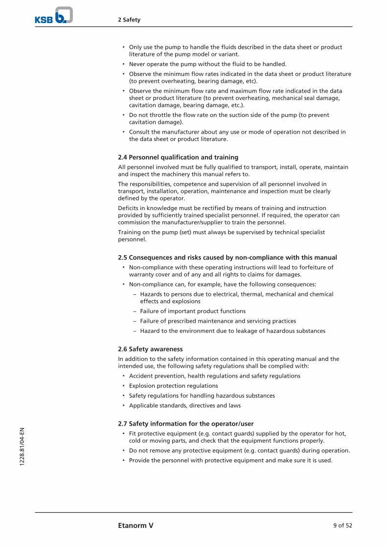
To transport the pump/pump set suspend it from the lifting tackle as shown.
Fig. 1: Transporting the pump set without/with cover plate up to motor size 160
NOTE
For pump sets with motors of size 180 or larger the pump and motor are suppliedseparately as the motor weighs more than the pump. The motor is mounted on site. If required, screw eyebolts for attaching the lifting gear into the threaded holes ofthe lantern.
3 Transport/Temporary Storage/Disposal
12 of 52 Etanorm V
1228
.81/
04-E
N
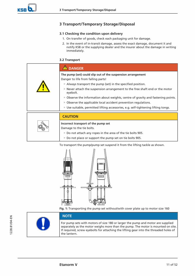
Fig. 2: Transporting the pump and motor from motor size 180 upwards
3.3 Storage/preservationIf commissioning is to take place some time after delivery, we recommend that thefollowing measures be taken for pump (set) storage.
CAUTION
Damage during storage due to humidity, dirt or vermin
Corrosion/contamination of the pump (set)!
▷ For outdoor storage cover the pump (set) or the packaged pump (set) andaccessories with waterproof material.
CAUTION
Wet, contaminated or damaged openings and connections
Leakage or damage to the pump!
▷ Clean and cover pump openings and connections as required prior to puttingthe pump into storage.
Store the pump (set) in a dry, protected room where the atmospheric humidity is asconstant as possible.
Rotate the shaft by hand once a month, e.g. via the motor fan.
If properly stored indoors, the pump set is protected for a maximum of 12 months.New pumps/pump sets are supplied by our factory duly prepared for storage.
For storing a pump (set) which has already been operated, the shutdown measuresmust be adhered to. (ð Section 6.3.1, Page 31)
3.4 Return to supplier1. Drain the pump as per operating instructions. (ð Section 7.4, Page 36)
2. Flush and clean the pump, particularly if it has been used for handling noxious,explosive, hot or other hazardous fluids. (ð Section 6.5, Page 32)
3. If the pump has handled fluids whose residues could lead to corrosion damagein the presence of atmospheric humidity or could ignite upon contact withoxygen also neutralise the pump and blow through with anhydrous inert gas toensure drying.
4. Always complete and enclose a certificate of decontamination when returningthe pump.Indicate any safety measures and decontamination measures taken.(ð Section 11, Page 50)
3 Transport/Temporary Storage/Disposal
13 of 52Etanorm V
1228
.81/
04-E
N
NOTE
If required, a blank certificate of decontamination can be downloaded from thefollowing web site: www.ksb.com/certificate_of_decontamination
3.5 Disposal
WARNING
Fluids handled, consumables and supplies which are hot and/or pose a healthhazard
Hazard to persons and the environment!
▷ Collect and properly dispose of flushing fluid and any fluid residues.
▷ Wear safety clothing and a protective mask if required.
▷ Observe all legal regulations on the disposal of fluids posing a health hazard.
1. Dismantle the pump (set).Collect greases and other lubricants during dismantling.
2. Separate and sort the pump materials, e.g. by:- Metals- Plastics- Electronic waste- Greases and other lubricants
3. Dispose of materials in accordance with local regulations or in anothercontrolled manner.
4 Description of the Pump (Set)
14 of 52 Etanorm V
1228
.81/
04-E
N
4 Description of the Pump (Set)
4.1 General description▪ Vertical low-pressure centrifugal pump
Pump for handling neutral degreasing and phosphating agents, wash water withdegreasing agents and electrodeposition paints.
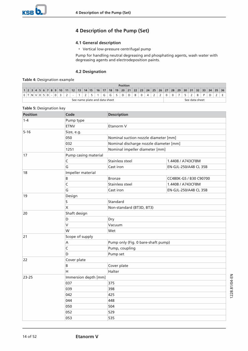
4.2 Designation
Table 4: Designation examplePosition
1 2 3 4 5 6 7 8 9 10 11 12 13 14 15 16 17 18 19 20 21 22 23 24 25 26 27 28 29 30 31 32 33 34 35 36
E T N V 0 5 0 - 0 3 2 - 1 2 5 1 G G S D D B 0 4 2 2 0 0 7 5 2 B P D 2 E
See name plate and data sheet See data sheet
Table 5: Designation key
Position Code Description
1-4 Pump type
ETNV Etanorm V
5-16 Size, e.g.
050 Nominal suction nozzle diameter [mm]
032 Nominal discharge nozzle diameter [mm]
1251 Nominal impeller diameter [mm]
17 Pump casing material
C Stainless steel 1.4408 / A743CF8M
G Cast iron EN-GJL-250/A48 CL 35B
18 Impeller material
B Bronze CC480K-GS / B30 C90700
C Stainless steel 1.4408 / A743CF8M
G Cast iron EN-GJL-250/A48 CL 35B
19 Design
S Standard
X Non-standard (BT3D, BT3)
20 Shaft design
D Dry
V Vacuum
W Wet
21 Scope of supply
A Pump only (Fig. 0 bare-shaft pump)
C Pump, coupling
D Pump set
22 Cover plate
B Cover plate
H Halter
23-25 Immersion depth [mm]
037 375
039 398
042 425
044 448
050 504
052 529
053 535

4 Description of the Pump (Set)
15 of 52Etanorm V
1228
.81/
04-E
N
Position Code Description
23-25 075 750
100 1000
125 1250
150 1500
170 1750
200 2000
26 Shaft unit
2 Shaft unit 25
3 Shaft unit 35
5 Shaft unit 55
27-30 Motor rating PN [kW]
0007 0,75
... ...
1320 132,00
---- Without motor
31 Number of motor poles
- Without motor
32 Product generation
B Etanorm V 2013
33-36 Variant
- Fixed speed version (without PumpDrive)
PD2 Variable speed version, with PumpDrive 2
PD2E Variable speed version, with PumpDrive 2 Eco
4.3 Name plate
KSB SE & Co. KGaAJohann-Klein-Straße 967227 Frankenthal
ZN 3823 - 217Mat. No. 01216137
ENTV 050-032-125.1 GG X DDB0422Etanorm V 47132456 Ø 174 mm
9971234567 000100 / 01Q 30,00 m³/h H 34,00 mv 1,0 mm²/s n 2900 1/min 2018
η --,-%
12345
67891011
Fig. 3: Name plate (example)
1 Type series code, size and version 2 Type series
3 KSB order No., order item No. andconsecutive No.
4 Flow rate
5 Kinematic viscosity of the fluidhandled
6 Material number (if applicable)
7 Impeller diameter 8 Head
9 Speed 10 Year of construction
11 Efficiency (see data sheet)
4 Description of the Pump (Set)
16 of 52 Etanorm V
1228
.81/
04-E
N
4.4 Design details
Design
▪ Volute casing pump
▪ For vertical installation in closed tanks under atmospheric pressure
▪ Single-stage
▪ Ratings to EN 733
▪ Rigid connection between pump and motor
Pump casing
▪ Radially split volute casing
Stainless steel variant / grey cast iron variant for design with shaft unit WS 55:
▪ Volute casing with integrally cast pump feet
▪ Replaceable casing wear rings
Drive
▪ KSB surface-cooled IEC three-phase current squirrel-cage motor
▪ Type of construction IM V1
▪ Rated voltage (50 Hz) 220-240 V / 380-420 V ≤ 2.20 kW
▪ Rated voltage (50 Hz) 380-420 V / 660 - 725 V ≥ 3.00 kW
▪ Rated voltage (60 Hz) 440-480 V ≤ 2.60 kW
▪ Rated voltage (60 Hz) 440-480 V ≥ 3.60 kW
▪ Enclosure IP55
▪ Thermal class F with temperature sensor, 3 PTC thermistors
▪ Duty cycle: continuous duty S1
Contact guard
Design D:
▪ Cover plates at bearing lantern to EN 294
Design W:
▪ Cover plates at drive lantern to EN 294
Shaft seal
▪ Controlled gap
Impeller type
▪ Closed radial impeller with multiply curved vanes
Bearings
Design D:
▪ Deep groove ball bearings greased for life in a bearing lantern above the coverplate, pump shaft cantilevered below the cover plate
Design W:
▪ Product-lubricated SiC/SiC plain bearing (pump end), rigid coupling betweenpump shaft and motor shaft
Automation
Automation options:
▪ PumpDrive
▪ KSB SuPremE
▪ Efficiency class IE4/IE5 to IEC TS 60034-30-2:2016
4 Description of the Pump (Set)
17 of 52Etanorm V
1228
.81/
04-E
N
For operating an Etanorm V on a frequency inverter which has not been configuredvia the KSB selection tool consultation with KSB is required.
For operating pump sets at immersion depths > 1000 mm with variable-speed systemconsultation with KSB is required for the selection.
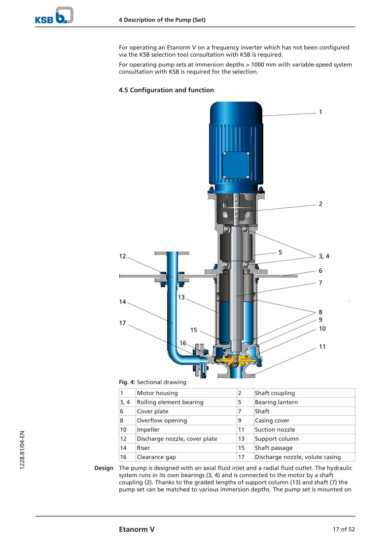
4.5 Configuration and function
1
2
53, 4
6
7
8910
11
12
1314
15
16
17
Fig. 4: Sectional drawing
1 Motor housing 2 Shaft coupling
3, 4 Rolling element bearing 5 Bearing lantern
6 Cover plate 7 Shaft
8 Overflow opening 9 Casing cover
10 Impeller 11 Suction nozzle
12 Discharge nozzle, cover plate 13 Support column
14 Riser 15 Shaft passage
16 Clearance gap 17 Discharge nozzle, volute casing
Design The pump is designed with an axial fluid inlet and a radial fluid outlet. The hydraulicsystem runs in its own bearings (3, 4) and is connected to the motor by a shaftcoupling (2). Thanks to the graded lengths of support column (13) and shaft (7) thepump set can be matched to various immersion depths. The pump set is mounted on
4 Description of the Pump (Set)
18 of 52 Etanorm V
1228
.81/
04-E
N
a cover plate (6). The discharge nozzle of the volute casing (17) is connected with thedischarge nozzle (12) of the cover plate via a riser (14). If on request the pump set issupplied without cover plate and riser, it is supplied with a bracket.
Function The fluid enters the pump via the suction nozzle (11) and is accelerated outward bythe rotating impeller (10). In the flow passage of the pump casing the kinetic energyof the fluid is converted into pressure energy. The fluid is pumped to the dischargenozzle (17), where it leaves the pump. The controlled gap seal (16) prevents any fluidfrom flowing back from the casing to the suction nozzle. At the rear side of theimpeller, the shaft (7) enters the hydraulic system through the casing cover (9). Theshaft runs in rolling element bearings (3 and 4), which are supported by a bearinglantern (5) linked with the pump casing and/or casing cover (9) via the supportcolumn (13).
Sealing The pump is seal-less with little leakage flowing into the support column (8) at theshaft passage (9) and then through the overflow opening (7) back to the tank.
4.6 Noise characteristics
Table 6: Surface sound pressure level LpA2)
Rated power inputPN [kW]
Pump set
1450 rpm [dB]
2900 rpm[dB]
2,2 64 69
3,0 64 71
4,0 62 73
5,5 68 72
7,5 68 72
11,0 69 75
15,0 69 75
18,5 70 75
22,0 72 78
30,0 71 79
37,0 71 79
45,0 73 79
55,0 74 79
75,0 75 82
90,0 76 82
In wet installation, the pump itself does not contribute to sound emission levels.
4.7 Scope of supplyDepending on the model, the following items are included in the scope of supply:
▪ Pump
▪ Drive
▪ Cover plate
▪ Discharge line
2) Surface sound pressure level as per ISO 3744; valid for pump operation in the Q/QBEP = 0.80 - 1.1 range and for non-cavitating operation. If noise levels are to be guaranteed: Add +3 dB for measuring and constructional tolerance.
4 Description of the Pump (Set)
19 of 52Etanorm V
1228
.81/
04-E
N
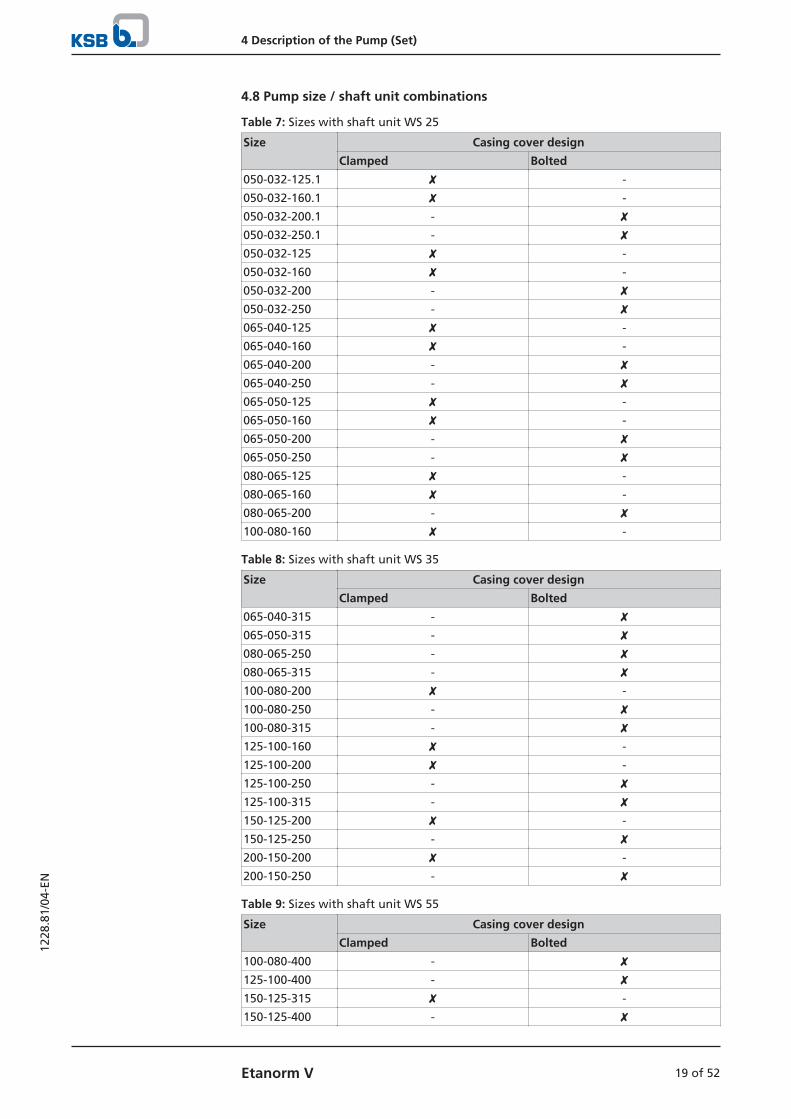
4.8 Pump size / shaft unit combinations
Table 7: Sizes with shaft unit WS 25
Size Casing cover design
Clamped Bolted
050-032-125.1 ✘ -
050-032-160.1 ✘ -
050-032-200.1 - ✘050-032-250.1 - ✘050-032-125 ✘ -
050-032-160 ✘ -
050-032-200 - ✘050-032-250 - ✘065-040-125 ✘ -
065-040-160 ✘ -
065-040-200 - ✘065-040-250 - ✘065-050-125 ✘ -
065-050-160 ✘ -
065-050-200 - ✘065-050-250 - ✘080-065-125 ✘ -
080-065-160 ✘ -
080-065-200 - ✘100-080-160 ✘ -
Table 8: Sizes with shaft unit WS 35
Size Casing cover design
Clamped Bolted
065-040-315 - ✘065-050-315 - ✘080-065-250 - ✘080-065-315 - ✘100-080-200 ✘ -
100-080-250 - ✘100-080-315 - ✘125-100-160 ✘ -
125-100-200 ✘ -
125-100-250 - ✘125-100-315 - ✘150-125-200 ✘ -
150-125-250 - ✘200-150-200 ✘ -
200-150-250 - ✘
Table 9: Sizes with shaft unit WS 55
Size Casing cover design
Clamped Bolted
100-080-400 - ✘125-100-400 - ✘150-125-315 ✘ -
150-125-400 - ✘

4 Description of the Pump (Set)
20 of 52 Etanorm V
1228
.81/
04-E
N
Size Casing cover design
Clamped Bolted
200-150-315 ✘ -
200-150-400 - ✘
4.9 Dimensions and weightsFor dimensions and weights please refer to the general arrangement drawing/outlinedrawing of the pump/pump set.

5 Installation at Site
21 of 52Etanorm V
1228
.81/
04-E
N
5 Installation at Site
5.1 Safety regulations
DANGER
Installing electric equipment (motors) in potentially explosive atmospheres
Risk of explosion!
▷ Comply with the applicable local explosion protection regulations.
▷ Verify the test certificate of the motor.
▷ Keep the test certificate close to the location of operation (e.g. in the foreman'soffice).
5.2 Checks to be carried out prior to installationCheck the structural requirements.The structural work required must have been prepared in accordance with thedimensions stated in the outline drawing and/or general arrangement drawing.
5.3 Installing the pump setFoundation The sturdy cover plate 68-3.01 serves as a foundation on which the pump set is
fastened. This cover plate covers the tank opening completely. If the pump set issupplied with cover plate and riser, the cover plate is supported by a sectional steelframe provided on the tank.
If ordered without cover plate and riser, the pump set is supplied with a bolted-onbracket 732. This bracket serves to mount the pump set on the tank.
Installing the pump
1. Carefully align the support for the cover plate or the base of the bracket.
2. Align the upper flange of the bearing/intermediate lantern with a spirit level.
3. Make adjustments between cover plate and tank edge, if required.If the pump is installed without a suction strainer, observe a minimum distanceB to the tank floor.

5 Installation at Site
22 of 52 Etanorm V
1228
.81/
04-E
N
BDN1
Fig. 5: Distance from the floor
Table 10: Distance from the floor in [mm]
DN1 B
50 ≥80
65 ≥80
80 ≥100
100 ≥100
125 ≥100
150 ≥150
200 ≥150
5 Installation at Site
23 of 52Etanorm V
1228
.81/
04-E
N
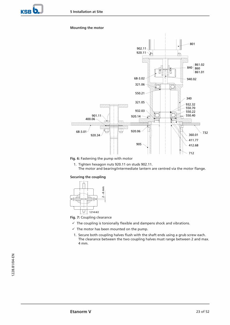
Mounting the motor
801
940.02
340
550.21
932.32550.70
321.06
550.40550.22
411.77
902.11920.11
68-3.02
920.14
840
732
905
360.01920.06
412.68
712
901.11400.06
68-3.01920.34
321.05
932.03
861.02 860 861.01
Fig. 6: Fastening the pump with motor
1. Tighten hexagon nuts 920.11 on studs 902.11.The motor and bearing/intermediate lantern are centred via the motor flange.
Securing the coupling
2 -
4 m
m
1214:4/2
Fig. 7: Coupling clearance
ü The coupling is torsionally flexible and dampens shock and vibrations.
ü The motor has been mounted on the pump.
1. Secure both coupling halves flush with the shaft ends using a grub screw each.The clearance between the two coupling halves must range between 2 and max.4 mm.
5 Installation at Site
24 of 52 Etanorm V
1228
.81/
04-E
N
5.4 Piping
5.4.1 Connecting the piping
DANGER
Impermissible loads acting on the pump nozzles
Danger to life from leakage of hot, toxic, corrosive or flammable fluids!
▷ Do not use the pump as an anchorage point for the piping.
▷ Anchor the pipes in close proximity to the pump and connect them properlywithout transmitting any stresses or strains.
▷ Take appropriate measures to compensate for thermal expansion of the piping.
CAUTION
Incorrect earthing during welding work at the piping
Destruction of rolling element bearings (pitting effect)!
▷ Never earth the electric welding equipment on the pump or baseplate.
▷ Prevent current flowing through the rolling element bearings.
NOTE
Installing check and shut-off elements in the system is recommended, depending onthe type of plant and pump. However, such elements must not obstruct properdrainage or hinder disassembly of the pump.
ü The nominal diameters of the pipelines are at least equal to the nominaldiameters of the pump nozzles.
ü To prevent excessive pressure losses, adapters to larger diameters have a diffuserangle of approx. 8°.
ü The pipeline is anchored in close proximity to the discharge flange andconnected without transmitting any stresses or strains. Its weight must not becarried by the pump discharge flange.
1. Thoroughly clean, flush and blow through all vessels, pipelines and connections(especially of new installations).
2. Check that the coupling and shaft can easily be rotated by hand.
5 Installation at Site
25 of 52Etanorm V
1228
.81/
04-E
N
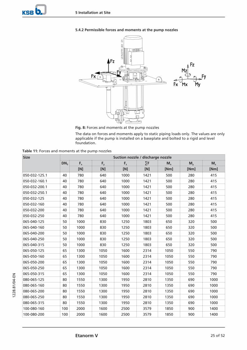
5.4.2 Permissible forces and moments at the pump nozzles
Fig. 8: Forces and moments at the pump nozzles
The data on forces and moments apply to static piping loads only. The values are onlyapplicable if the pump is installed on a baseplate and bolted to a rigid and levelfoundation.
Table 11: Forces and moments at the pump nozzles
Size Suction nozzle / discharge nozzle
DN3 Fx Fy Fz ∑F Mx My Mz
[N] [N] [N] [N] [Nm] [Nm] [Nm]
050-032-125.1 40 780 640 1000 1421 500 280 415
050-032-160.1 40 780 640 1000 1421 500 280 415
050-032-200.1 40 780 640 1000 1421 500 280 415
050-032-250.1 40 780 640 1000 1421 500 280 415
050-032-125 40 780 640 1000 1421 500 280 415
050-032-160 40 780 640 1000 1421 500 280 415
050-032-200 40 780 640 1000 1421 500 280 415
050-032-250 40 780 640 1000 1421 500 280 415
065-040-125 50 1000 830 1250 1803 650 320 500
065-040-160 50 1000 830 1250 1803 650 320 500
065-040-200 50 1000 830 1250 1803 650 320 500
065-040-250 50 1000 830 1250 1803 650 320 500
065-040-315 50 1000 830 1250 1803 650 320 500
065-050-125 65 1300 1050 1600 2314 1050 550 790
065-050-160 65 1300 1050 1600 2314 1050 550 790
065-050-200 65 1300 1050 1600 2314 1050 550 790
065-050-250 65 1300 1050 1600 2314 1050 550 790
065-050-315 65 1300 1050 1600 2314 1050 550 790
080-065-125 80 1550 1300 1950 2810 1350 690 1000
080-065-160 80 1550 1300 1950 2810 1350 690 1000
080-065-200 80 1550 1300 1950 2810 1350 690 1000
080-065-250 80 1550 1300 1950 2810 1350 690 1000
080-065-315 80 1550 1300 1950 2810 1350 690 1000
100-080-160 100 2000 1600 2500 3579 1850 900 1400
100-080-200 100 2000 1600 2500 3579 1850 900 1400
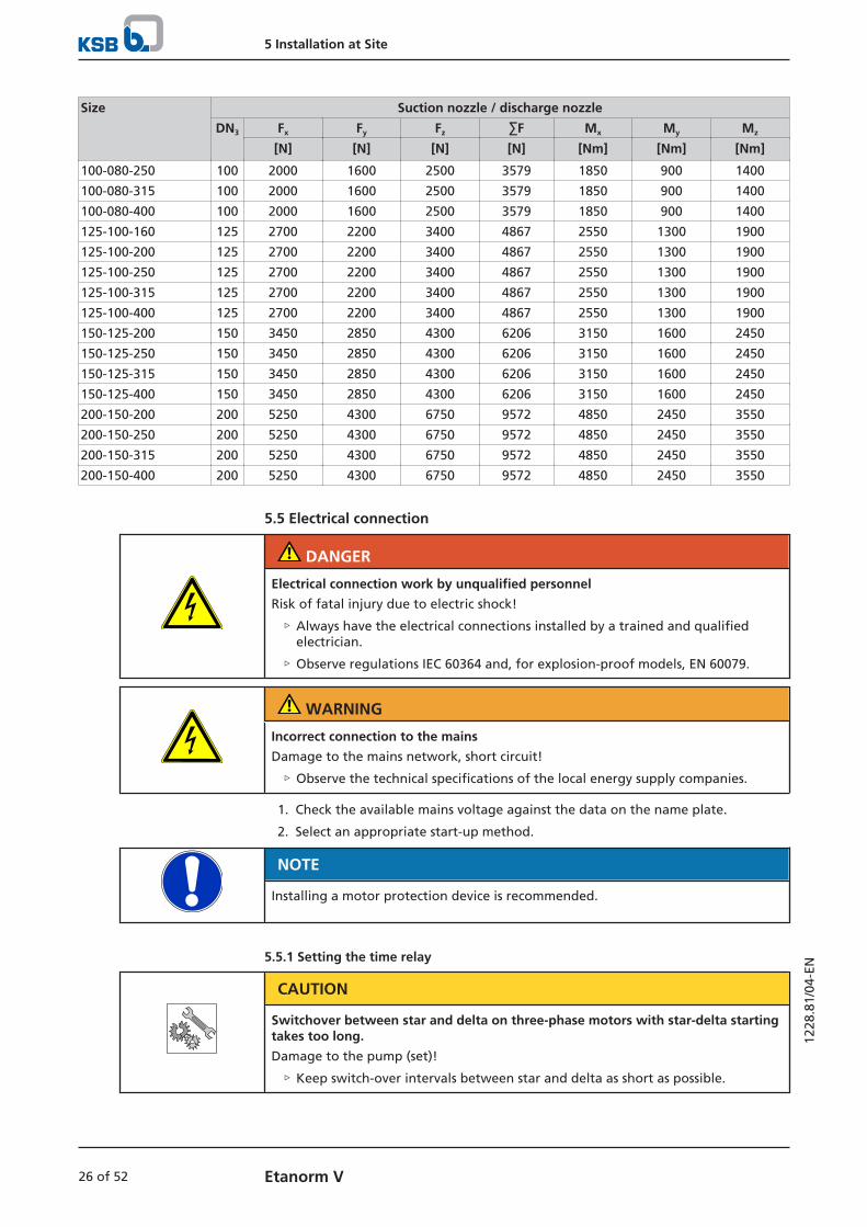
5 Installation at Site
26 of 52 Etanorm V
1228
.81/
04-E
N
Size Suction nozzle / discharge nozzle
DN3 Fx Fy Fz ∑F Mx My Mz
[N] [N] [N] [N] [Nm] [Nm] [Nm]
100-080-250 100 2000 1600 2500 3579 1850 900 1400
100-080-315 100 2000 1600 2500 3579 1850 900 1400
100-080-400 100 2000 1600 2500 3579 1850 900 1400
125-100-160 125 2700 2200 3400 4867 2550 1300 1900
125-100-200 125 2700 2200 3400 4867 2550 1300 1900
125-100-250 125 2700 2200 3400 4867 2550 1300 1900
125-100-315 125 2700 2200 3400 4867 2550 1300 1900
125-100-400 125 2700 2200 3400 4867 2550 1300 1900
150-125-200 150 3450 2850 4300 6206 3150 1600 2450
150-125-250 150 3450 2850 4300 6206 3150 1600 2450
150-125-315 150 3450 2850 4300 6206 3150 1600 2450
150-125-400 150 3450 2850 4300 6206 3150 1600 2450
200-150-200 200 5250 4300 6750 9572 4850 2450 3550
200-150-250 200 5250 4300 6750 9572 4850 2450 3550
200-150-315 200 5250 4300 6750 9572 4850 2450 3550
200-150-400 200 5250 4300 6750 9572 4850 2450 3550
5.5 Electrical connection
DANGER
Electrical connection work by unqualified personnel
Risk of fatal injury due to electric shock!
▷ Always have the electrical connections installed by a trained and qualifiedelectrician.
▷ Observe regulations IEC 60364 and, for explosion-proof models, EN 60079.
WARNING
Incorrect connection to the mains
Damage to the mains network, short circuit!
▷ Observe the technical specifications of the local energy supply companies.
1. Check the available mains voltage against the data on the name plate.
2. Select an appropriate start-up method.
NOTE
Installing a motor protection device is recommended.
5.5.1 Setting the time relay
CAUTION
Switchover between star and delta on three-phase motors with star-delta startingtakes too long.
Damage to the pump (set)!
▷ Keep switch-over intervals between star and delta as short as possible.
5 Installation at Site
27 of 52Etanorm V
1228
.81/
04-E
N
Table 12: Time relay settings for star-delta starting:
Motor rating Y time to be set
[kW] [s]
≤ 30 < 3
> 30 < 5
5.5.2 Connecting the motor
NOTE
In compliance with IEC 60034-8, three-phase motors are always wired for clockwiserotation (looking at the motor shaft stub).
The pump's direction of rotation is indicated by an arrow on the pump.
1. Match the motor's direction of rotation to that of the pump.
2. Observe the manufacturer's product literature supplied with the motor.
5.6 Checking the direction of rotation
WARNING
Hands inside the pump casing
Risk of injuries, damage to the pump!
▷ Always disconnect the pump set from the power supply and secure it againstunintentional start-up before inserting your hands or other objects into thepump.
WARNING
Reaching into the bearing lantern opening
Risk of injury!
▷ When the cover plate is removed, never reach into the uncovered opening.
CAUTION
Drive and pump running in the wrong direction of rotation
Damage to the pump!
▷ Refer to the arrow indicating the direction of rotation on the pump.
▷ Check the direction of rotation. If required, check the electrical connection andcorrect the direction of rotation.
The correct direction of rotation of the motor and pump is clockwise (seen from themotor end).
1. Start the motor and stop it again immediately to determine the motor'sdirection of rotation.
2. Check the direction of rotation. The motor's direction of rotation must match the arrow indicating the directionof rotation on the drive lantern / bearing lantern.
3. If the motor is running in the wrong direction of rotation, check the electricalconnection of the motor and the control system, if applicable.
6 Commissioning/Start-up/Shutdown
28 of 52 Etanorm V
1228
.81/
04-E
N
6 Commissioning/Start-up/Shutdown
6.1 Commissioning/Start-up
6.1.1 Prerequisites for commissioning/start-up
Before commissioning/starting up the pump set, make sure that the followingconditions are met:
▪ The pump set has been properly connected to the power supply and is equippedwith all protection devices.
▪ The pump has been primed with the fluid to be handled. The pump has beenvented. (ð Section 6.1.3, Page 28)
▪ The direction of rotation has been checked. (ð Section 5.6, Page 27)
▪ All auxiliary connections required are connected and operational.
▪ The lubricants have been checked.
▪ After prolonged shutdown of the pump (set), the activities required for returningthe equipment to service have been carried out. (ð Section 6.4, Page 31)
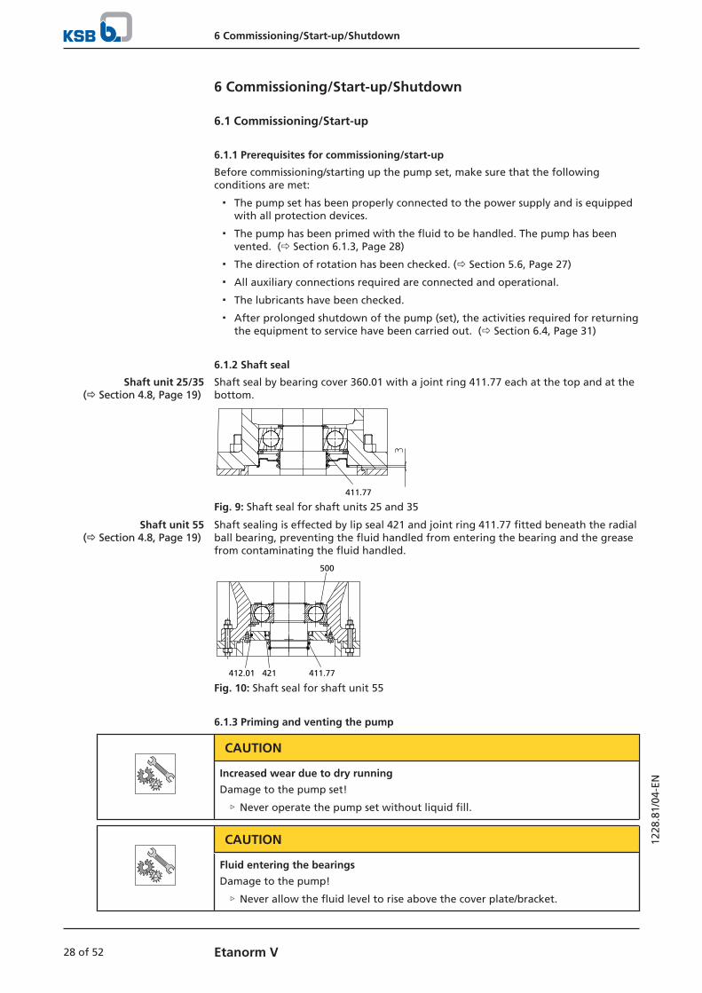
6.1.2 Shaft seal
Shaft unit 25/35(ð Section 4.8, Page 19)
Shaft seal by bearing cover 360.01 with a joint ring 411.77 each at the top and at thebottom.
411.77
Fig. 9: Shaft seal for shaft units 25 and 35
Shaft unit 55(ð Section 4.8, Page 19)
Shaft sealing is effected by lip seal 421 and joint ring 411.77 fitted beneath the radialball bearing, preventing the fluid handled from entering the bearing and the greasefrom contaminating the fluid handled.
500
411.77421412.01
Fig. 10: Shaft seal for shaft unit 55
6.1.3 Priming and venting the pump
CAUTION
Increased wear due to dry running
Damage to the pump set!
▷ Never operate the pump set without liquid fill.
CAUTION
Fluid entering the bearings
Damage to the pump!
▷ Never allow the fluid level to rise above the cover plate/bracket.
6 Commissioning/Start-up/Shutdown
29 of 52Etanorm V
1228
.81/
04-E
N
During pump start-up and operation, the fluid level must be within 130 mm abovethe volute casing centreline and 50 mm below the cover plate/bracket.
6.1.4 Start-up
CAUTION
Abnormal noises, vibrations, temperatures or leakage
Damage to the pump!
▷ Switch off the pump (set) immediately.
▷ Eliminate the causes before returning the pump set to service.
ü The system piping has been cleaned.
ü Pump, suction line and inlet tank, if any, have been vented and primed with thefluid to be handled.
ü The fluid level has been checked.
1. Close or slightly open the shut-off element in the discharge line.
2. Start up the motor.
3. Immediately after the pump has reached full rotational speed, slowly open theshut-off element in the discharge line and adjust it to comply with the dutypoint.
6.1.5 Shutdown
1. Close the shut-off element in the discharge line.
2. Switch off the motor and make sure the pump set runs down smoothly to astandstill.
NOTE
If the discharge line is equipped with a non-return or check valve, the shut-offelement may remain open provided that the system conditions and systemregulations are considered and observed.
CAUTION
Risk of freezing during prolonged pump shutdown periods
Damage to the pump!
▷ Drain the pump and the cooling/heating chambers (if any) or otherwise protectthem against freezing.
6.2 Operating limits
DANGER
Non-compliance with operating limits for pressure, temperature and speed
Explosion hazard!
Leakage of hot or toxic fluid handled!
▷ Comply with the operating data indicated in the data sheet.
▷ Never use the pump to handle fluids it is not designed for.
▷ Avoid prolonged operation against a closed shut-off element.
▷ Never operate the pump at temperatures exceeding those specified in the datasheet or on the name plate unless the written consent of the manufacturer hasbeen obtained.
6 Commissioning/Start-up/Shutdown
30 of 52 Etanorm V
1228
.81/
04-E
N
6.2.1 Ambient temperature
CAUTION
Operation outside the permissible ambient temperature
Damage to the pump (set)!
▷ Observe the specified limits for permissible ambient temperatures.
Observe the following parameters and values during operation:
Table 13: Permissible ambient temperatures
Permissible ambient temperature Value
Maximum 40 °C
Minimum See data sheet.
6.2.2 Frequency of starts
The frequency of starts is usually determined by the maximum temperature increaseof the motor. This largely depends on the power reserves of the motor in steady-state operation and on the starting conditions (DOL, star-delta, moments of inertia,etc). If the starts are evenly spaced over the period indicated, the following limitsserve as orientation for start-up with the discharge-side gate valve slightly open:
To prevent high temperature increases in the motor and excessive loads on thepump, coupling, motor, seals and bearings, do not exceed 10 start-ups per hour [h].
CAUTION
Re-starting while motor is still running down
Damage to the pump (set)!
▷ Do not re-start the pump set before the pump rotor has come to a standstill.
6.2.3 Fluid handled
6.2.3.1 Flow rate
Table 14: Flow rate
Minimum flow rate Maximum flow rate
For a short period(approximately 2 minutes)
15 % of QBEP.3) See hydraulic characteristic
curves
Continuous operation Qlow flow ≥ 50 % of QBEP3)
6.2.3.2 Density of the fluid handled
The power input of the pump set will change in proportion to the density of the fluidhandled.
CAUTION
Impermissibly high density of the fluid handled
Motor overload!
▷ Observe the information about fluid density in the data sheet.
▷ Make sure the motor has sufficient power reserves.
3) Best efficiency point

6 Commissioning/Start-up/Shutdown
31 of 52Etanorm V
1228
.81/
04-E
N
6.2.3.3 Temperature of the fluid handled
CAUTION
Evaporated fluid washes lubricant out of the bearing
Damage to the bearings!
▷ Never exceed the fluid temperature of 70 ℃.
▷ The fluid temperature must remain at least 5 °C below the boiling point.
6.2.3.4 Abrasive fluids
When the pump handles fluids containing abrasive substances, increased wear of thehydraulic system and the shaft seal are to be expected. In this case, reduce thecommonly recommended inspection intervals.
The fluid handled may contain non-abrasive particles up to a maximum content of5 g/m³ and a maximum particle size of 0.5 mm.
6.3 Shutdown/storage/preservation
6.3.1 Measures to be taken for shutdown
The pump (set) remains installed
ü Sufficient fluid is supplied for the functional check run of the pump.
1. For prolonged shutdown periods, start up the pump (set) regularly betweenonce a month and once every three months for approximately five minutes.
ð This will prevent the formation of deposits within the pump and the pumpintake area.
The pump (set) is removed from the pipe and stored
ü The pump has been properly drained. (ð Section 7.4, Page 36)
ü The safety instructions for dismantling the pump have been observed.(ð Section 7.5.1, Page 36)
1. Spray-coat the inside wall of the pump casing and, in particular, the impellerclearance areas with a preservative.
2. Spray the preservative through the suction nozzle and discharge nozzle.It is advisable to then close the pump nozzles (e.g. with plastic caps).
3. Oil or grease all exposed machined parts and surfaces of the pump (withsilicone-free oil or grease, food-approved if required) to protect them againstcorrosion.Observe the additional instructions on preservation. (ð Section 3.3, Page 12)
If the pump set is to be stored temporarily, only preserve the wetted componentsmade of low-alloy materials. Commercially available preservatives can be used forthis purpose. Observe the manufacturer's instructions for application/removal.
6.4 Returning to serviceFor returning the equipment to service observe the sections on commissioning/start-up and the operating limits. (ð Section 6.1, Page 28)
In addition, carry out all servicing/maintenance operations before returning thepump (set) to service. (ð Section 7, Page 33)
WARNING
Failure to re-install or re-activate protective devices
Risk of injury from moving parts or escaping fluid!
▷ As soon as the work is completed, properly re-install and re-activate any safety-relevant devices and protective devices.
6 Commissioning/Start-up/Shutdown
32 of 52 Etanorm V
1228
.81/
04-E
N
NOTE
If the equipment has been out of service for more than one year, replace allelastomer seals.
6.5 Cleaning the pump set
CAUTION
Cleaning the pump set
Damage to the coupling and bearing!
▷ Never allow spray water to enter the coupling and bearing area through thebearing lantern's cover plate.
NOTE
For the electric motor observe the manufacturer´s product literature.
7 Servicing/Maintenance
33 of 52Etanorm V
1228
.81/
04-E
N
7 Servicing/Maintenance
7.1 Safety regulationsThe operator ensures that maintenance, inspection and installation are performed byauthorised, qualified specialist personnel who are thoroughly familiar with themanual.
WARNING
Unintentional starting of the pump set
Risk of injury by moving components and shock currents!
▷ Ensure that the pump set cannot be started unintentionally.
▷ Always make sure the electrical connections are disconnected before carryingout work on the pump set.
WARNING
Fluids handled, consumables and supplies which are hot and/or pose a healthhazard
Risk of injury!
▷ Observe all relevant laws.
▷ When draining the fluid take appropriate measures to protect persons and theenvironment.
▷ Decontaminate pumps which handle fluids posing a health hazard.
WARNING
Insufficient stability
Risk of crushing hands and feet!
▷ During assembly/dismantling, secure the pump (set)/pump parts to preventtilting or tipping over.
A regular maintenance schedule will help avoid expensive repairs and contribute totrouble-free, reliable operation of the pump, pump set and pump parts with aminimum of servicing/maintenance expenditure and work.
NOTE
All maintenance work, service work and installation work can be carried out by KSBService or authorised workshops. For contact details please refer to the enclosed"Addresses" booklet or visit "www.ksb.com/contact" on the Internet.
Never use force when dismantling and reassembling the pump set.
7.2 Servicing/Inspection
7.2.1 Supervision of operation
CAUTION
Increased wear due to dry running
Damage to the pump set!
▷ Never operate the pump set without liquid fill.
▷ Never close the shut-off element in the suction line and/or supply line duringpump operation.

7 Servicing/Maintenance
34 of 52 Etanorm V
1228
.81/
04-E
N
CAUTION
Impermissibly high temperature of fluid handled
Damage to the pump!
▷ Prolonged operation against a closed shut-off element is not permitted(heating up of the fluid).
▷ Observe the temperature limits in the data sheet and in the section onoperating limits.
While the pump is in operation, observe and check the following:
▪ The pump must run quietly and free from vibrations at all times.
▪ Check the shaft seal.
▪ Check the static seals for leakages.
▪ Check the rolling element bearings for running noises.Vibrations, noise and an increase in current input occurring during unchangedoperating conditions indicate wear.
▪ Monitor the stand-by pump.To make sure that the stand-by pumps are ready for operation, start them uponce a week.
▪ Monitor the bearing temperature.The bearing temperature must not exceed 90 °C (measured on the outside of themotor housing).
CAUTION
Operation outside the permissible bearing temperature
Damage to the pump!
▷ The bearing temperature of the pump (set) must never exceed 90 °C (measuredon the outside of the motor housing).
NOTE
After commissioning, increased temperatures may occur at grease-lubricated rollingelement bearings due to the running-in process. The final bearing temperature isonly reached after a certain period of operation (up to 48 hours depending on theconditions).
7.2.2 Inspection work
7.2.2.1 Checking the coupling
Check the flexible elements of the coupling. Replace the relevant parts in due time ifthere is any sign of wear and check the alignment.
7.2.2.2 Checking the clearances
If the clearances need to be checked, remove the impeller. If the clearance gap islarger or smaller than permitted (see the following table), replace casing wear rings502.01 and/or 502.02.The clearances given refer to the diameter.
7 Servicing/Maintenance
35 of 52Etanorm V
1228
.81/
04-E
N
Table 15: Clearances between impeller and casing / between impeller and casingcover depending on the material variant
Clearances Material variant
GG CC
As-new 0,3 mm 0,5 mm
Maximum permissibleenlargement
0,9 mm 1,5 mm
7.3 Lubrication and lubricant change of rolling element bearings
7.3.1 Grease lubrication
The bearings are supplied packed with high-quality lithium-soap grease.
7.3.1.1 Intervals
Under normal conditions the grease-lubricated bearings will run for 15,000 operatinghours or 2 years. Under unfavourable operating conditions (e.g. high roomtemperature, high atmospheric humidity, dust-laden air, aggressive industrialatmosphere etc.), check the bearings earlier and clean and relubricate them ifrequired.
7.3.1.2 Grease quality
Optimum grease properties for rolling element bearings
Table 16: Grease quality to DIN 51825
Soap basis NLGI grade Worked penetration at25° C in mm/10
Drop point
Lithium 2 to 3 220-295 ≥ 175 °C
▪ Free of resin and acid
▪ Not liable to crumble
▪ Rust-preventive characteristics
If required, the bearings may be lubricated with greases of other soap bases.Make sure to remove any old grease and rinse the bearings thoroughly.
7.3.1.3 Grease quantity
Shaft unit4) Pump end Motor end
Code Grease perbearing
(approx. qty. ingrams)
Code Grease perbearing
(approx. qty. ingrams)
25 63112ZC3 22 63102ZC3 22
35 63112ZC3 22 63102ZC3 22
55 6413C35) 65 63112ZC3 65
4) Shaft unit see data sheet.5) Axial sealing ring (Nilos ring)
7 Servicing/Maintenance
36 of 52 Etanorm V
1228
.81/
04-E
N
7.3.1.4 Changing the grease
CAUTION
Mixing greases of differing soap bases
Changed lubricating qualities!
▷ Thoroughly clean the bearings.
▷ Adjust the re-lubrication intervals to the grease used.
ü The pump has been dismantled for changing the grease.
1. Only half-fill the bearing cavities with grease.
7.4 Drainage/cleaning
WARNING
Fluids handled, consumables and supplies which are hot and/or pose a healthhazard
Hazard to persons and the environment!
▷ Collect and properly dispose of flushing fluid and any fluid residues.
▷ Wear safety clothing and a protective mask if required.
▷ Observe all legal regulations on the disposal of fluids posing a health hazard.
1. Use connection 6B to drain the fluid handled (see drawing of auxiliaryconnections).
2. Always flush the system if it has been used for handling noxious, explosive, hotor other hazardous fluids.Always flush and clean the pump before transporting it to the workshop.Provide a certificate of decontamination for the pump. (ð Section 11, Page 50)
7.5 Dismantling the pump set
7.5.1 General information/Safety regulations
DANGER
Insufficient preparation of work on the pump (set)
Risk of injury!
▷ Properly shut down the pump set.
▷ Close the shut-off elements in the suction line and discharge line.
▷ Drain the pump and release the pump pressure. (ð Section 7.4, Page 36)
▷ Shut off any auxiliary feed lines.
▷ Allow the pump set to cool down to ambient temperature.
WARNING
Unqualified personnel performing work on the pump (set)
Risk of injury!
▷ Always have repair work and maintenance work performed by specially trained,qualified personnel.

7 Servicing/Maintenance
37 of 52Etanorm V
1228
.81/
04-E
N
WARNING
Hot surface
Risk of injury!
▷ Allow the pump set to cool down to ambient temperature.
WARNING
Improper lifting/moving of heavy assemblies or components
Personal injury and damage to property!
▷ Use suitable transport devices, lifting equipment and lifting tackle to moveheavy assemblies or components.
Always observe the safety instructions and information. (ð Section 7.1, Page 33)
For any work on the motor, observe the instructions of the relevant motormanufacturer.
For dismantling and reassembly observe the exploded views and the generalassembly drawing.
In the event of damage you can always contact our service departments.
NOTE
All maintenance work, service work and installation work can be carried out by KSBService or authorised workshops. For contact details please refer to the enclosed"Addresses" booklet or visit "www.ksb.com/contact" on the Internet.
NOTE
After a prolonged period of operation the individual components may be hard topull off the shaft. If this is the case, use a brand name penetrating agent and/or - ifpossible - an appropriate puller.
7.5.2 Preparing the pump set
1. De-energise the pump set and secure it against unintentional start-up.
2. Reduce pressure in the piping by opening a consumer installation.
3. Disconnect and remove all auxiliary pipework.
7.5.3 Removing the complete pump set from the piping
ü The notes and steps stated in (ð Section 7.5.1, Page 36) to (ð Section 7.5.2, Page 37) have been observed/carried out.
1. Unbolt the discharge nozzle from the pipeline.
2. Undo the bolts fastening the cover plate.
3. Remove the complete pump set with the cover plate from the tank opening.

7 Servicing/Maintenance
38 of 52 Etanorm V
1228
.81/
04-E
N
7.5.4 Removing the motor
WARNING
Motor tipping over
Risk of crushing hands and feet!
▷ Suspend or support the motor to prevent it from tipping over.
ü The notes and steps stated in (ð Section 7.5.1, Page 36) to(ð Section 7.5.3, Page 37) have been observed/carried out.
ü The removed pump with cover plate 68-3.01 is placed horizontally on a suitablebase in a clean and level assembly area.
ü A drip pan collecting any fluid escaping has been placed under the pump alongthe latter's entire length.
1. Remove cover plates 68-3.02 from bearing lantern 340.
2. Undo hexagon nuts 920.11.
3. Pull motor 801 off bearing lantern 340.
7.5.5 Removing the riser
ü The notes and steps stated in (ð Section 7.5.1, Page 36) to(ð Section 7.5.4, Page 38) have been observed/carried out.
1. Remove nuts 920.34/920.19 and bolts 901.11/901.39.
2. Remove riser 711.
3. Remove gaskets 400.06/400.16.
7.5.6 Removing the volute casing and support column
Clamped casing cover 161 - combination see (ð Section 4.8, Page 19)
ü The notes and steps stated in (ð Section 7.5.1, Page 36) to(ð Section 7.5.5, Page 38) have been observed/carried out.
1. Undo and remove nuts 920.14/920.06.
2. Remove volute casing 102 with tie bolts 905.
3. Dispose of gasket 400.10.
4. Remove impeller nut 920.95 with disc 550.95 (shaft unit 25 only), safety device930.95 and impeller 230.
5. Separate casing cover 161, support column 712 and cover plate 68-3.01 orbracket 732.
Bolted casing cover 161 - combination see (ð Section 4.8, Page 19)
ü The notes and steps stated in (ð Section 7.5.1, Page 36) to (ð Section 7.5.5, Page 38) have been observed/carried out.
1. Undo and remove nuts 920.01.
2. Remove volute casing 102.
3. Dispose of gasket 400.10.
4. Remove impeller nut 920.95 with disc 550.95 (shaft unit 25 only), safety device930.95 and impeller 230.
5. Undo and remove nuts 920.14/920.06.
6. Remove casing cover 161 and tie bolts 905.
7. Separate support column 712, cover plate 68-3.01 and/or bracket 732.
7 Servicing/Maintenance
39 of 52Etanorm V
1228
.81/
04-E
N
7.5.7 Removing the bearing lantern with shaft
Shaft unit 25/35(ð Section 4.8, Page 19)
ü The notes and steps stated in (ð Section 7.5.1, Page 36) to(ð Section 7.5.6, Page 38) have been observed/carried out.
ü O-ring 412.68 and joint ring 411.77 have been removed from the shaft.
1. Pull bearing cover 360.01 off with a suitable tool.
2. Remove joint ring 411.77.
Shaft unit 55(ð Section 4.8, Page 19)
ü The notes and steps stated in (ð Section 7.5.1, Page 36) to(ð Section 7.5.6, Page 38) have been observed/carried out.
ü O-ring 412.68 and joint ring 411.77 have been removed from the shaft.
1. Remove bolts 901.36.
2. Remove bearing cover 360.01 with lip seal 421 and O-ring 412.01.
3. Undo the grub screw on coupling half 861.01.
4. Pull off coupling half 861.01 using a puller.
5. Remove key 940.02 from the keyway in shaft 210.
6. Remove circlip 932.03 and spacer disc 550.40 from the bearing lantern.
7. Carefully press the shaft with ball bearing out of the bearing lantern.
8. Pull deep groove ball bearing 321.06 off shaft 210.
9. Remove disc 550.21.
10. Remove circlip 932.32 with disc 550.70.
11. Pull deep groove ball bearing 321.05 off shaft 210.
12. Remove disc 550.22 from the shaft.
7.6 Reassembling the pump set
7.6.1 General information/Safety regulations
WARNING
Improper lifting/moving of heavy assemblies or components
Personal injury and damage to property!
▷ Use suitable transport devices, lifting equipment and lifting tackle to moveheavy assemblies or components.
CAUTION
Improper reassembly
Damage to the pump!
▷ Reassemble the pump (set) in accordance with the general rules of soundengineering practice.
▷ Use original spare parts only.
Sequence Always reassemble the pump in accordance with the corresponding general assemblydrawing or exploded view.
Sealing elements Check O-rings for any damage and replace by new O-rings if required.
Always use new gaskets, making sure that they have the same thickness as the oldones.
Always fit gaskets of asbestos-free materials or graphite without using lubricants(e.g. copper grease, graphite paste).
Assembly adhesives Avoid the use of assembly adhesives if possible.
Should an assembly adhesive be required after all, use a commercially availablecontact adhesive (e.g. Pattex) or sealant (e.g. HYLOMAR or Epple 33).
Only apply adhesive at selected points and in thin layers.
7 Servicing/Maintenance
40 of 52 Etanorm V
1228
.81/
04-E
N
Never use quick-setting adhesives (cyanoacrylate adhesives).
Coat the locating surfaces of the individual components with graphite or similarbefore reassembly.
Prior to reassembly, screw back any forcing screws and adjusting screws.
Tightening torques For reassembly, tighten all screws and bolts as specified in this manual. (ð Section 7.7, Page 42)
7.6.2 Fitting the bearing lantern with shaft
Shaft unit 25/35(ð Section 4.8, Page 19)
ü The individual parts are kept in a clean and level assembly area.
ü All dismantled parts have been cleaned and checked for wear.
ü Any damaged or worn parts have been replaced by original spare parts.
ü The sealing surfaces have been cleaned.
1. Slide disc 550.22 onto the shaft.
2. Slide radial ball bearing 321.05 onto shaft 210.
3. Fit disc 550.70 with circlip 932.32.
4. Slide disc 550.21 upwards.
5. Slide radial ball bearing 321.06 onto shaft 210.
6. Carefully press the shaft with ball bearing into bearing lantern 340.
7. Fasten spacer disc 550.40 and circlip 932.03 in the bearing lantern.
8. Press key 940.02 into the keyway of shaft 210.
9. Fit coupling half 861.01.
10. Tighten the grub screw on coupling half 861.01.
11. Fit joint ring 411.77.
12. Press in bearing cover 360.01 with a suitable tool. Distance 3 mm (ð Section 6.1.2, Page 28)
13. Slide joint ring 411.77 and O-ring 412.68 onto shaft 210.
Shaft unit 55(ð Section 4.8, Page 19)
ü The individual parts are kept in a clean and level assembly area.
ü All dismantled parts have been cleaned and checked for wear.
ü Any damaged or worn parts have been replaced by original spare parts.
ü The sealing surfaces have been cleaned.
1. Slide radial ball bearing 321.05 onto shaft 210.
2. Fit axial sealing ring 500 (Nilos ring) and disc 550.70 with circlip 932.32.
3. Slide disc 550.21 upwards.
4. Slide radial ball bearing 321.06 onto shaft 210.
5. Carefully press the shaft with ball bearing into bearing lantern 340.
6. Fasten spacer disc 550.40 and circlip 932.03 in the bearing lantern.
7. Press key 940.02 into the keyway of shaft 210.
8. Fit coupling half 861.01.
9. Tighten the grub screw on coupling half 861.01.
10. Fit bearing cover 360.01 with lip seal 421.01.
11. Tighten bolts 901.36.
12. Slide joint ring 411.77 and O-ring 412.68 onto the shaft.
7 Servicing/Maintenance
41 of 52Etanorm V
1228
.81/
04-E
N
7.6.3 Installing the volute casing and support column
Clamped casing cover 161 - combination see (ð Section 4.8, Page 19)
ü The notes and steps stated in (ð Section 7.6.1, Page 39) to(ð Section 7.6.2, Page 40) have been observed / carried out.
ü Bearing lantern 340 has been placed in a clean and level assembly area and isprotected against tipping over.
1. Place cover plate 68-3.01 or bracket 732 on bearing lantern 340 and support itto make sure it lies flush.
2. Fit support column 712 on bearing lantern 340.
3. Place casing cover 161 on the support column.
4. Fit gasket 400.10 on casing cover 161. (ð Section 7.6.1, Page 39)
5. Fit key 940.01 in shaft 210.
6. Fit impeller 230 on shaft 210 with disc 550.95 (shaft unit 25 only), safety device930.95 and impeller nut 920.95.
7. When screwing on tie bolts 905 use the shorter thread end to screw them tovolute casing 102. Screw nuts 920.06 to tie bolts 905, then guide the tie boltsthrough support column 712 into the drilled holes of cover plate 68-3.01 andbearing lantern 340.
8. Tighten nuts 920.14. Nuts 920.06 must remain accessible. (ð Section 7.7, Page 42)
9. Use nuts 920.06 to clamp cover plate 68-3.01 to bearing lantern 340.
Bolted casing cover 161 - combination see (ð Section 4.8, Page 19)
ü The notes and steps stated in (ð Section 7.6.1, Page 39) to(ð Section 7.6.2, Page 40) have been observed / carried out.
ü Bearing lantern 340 has been placed in a clean and level assembly area and isprotected against tipping over.
1. Place cover plate 68-3.01 or bracket 732 on bearing lantern 340 and support itto make sure it lies flush.
2. Fit support column 712 on bearing lantern 340.
3. Fit key 940.01 in shaft 210.
4. When screwing on tie bolts 905 use the shorter thread end to screw them intocasing cover 161. Screw nuts 920.06 to tie bolts 905, then guide the tie boltsthrough support column 712 into the drilled holes of cover plate 68-3.01 andbearing lantern 340.
5. Tighten nuts 920.14. Nuts 920.06 must remain accessible. (ð Section 7.7, Page 42)
6. Use nuts 920.06 to clamp cover plate 68-3.01 to bearing lantern 340.
7. Fit gasket 400.10 on casing cover 161. (ð Section 7.6.1, Page 39)
8. Fit impeller 230 on the shaft with disc 550.95 (shaft unit 25 only), safety device930.95 and impeller nut 920.95.
9. Place volute casing 102 on discharge cover 161.
10. Bolt volute casing to casing cover 161 with nuts 920.01. (ð Section 7.7, Page 42)
7.6.4 Installing the riser
ü The notes and steps stated in (ð Section 7.6.1, Page 39) to(ð Section 7.6.3, Page 41) have been observed/carried out.
1. Fit new gaskets 400.06/400.16 at the flanges connecting it to the pump and tothe cover plate. (ð Section 7.6.1, Page 39)
2. Fasten riser 711 with nuts 920.19/920.34 and bolts 901.11/901.39.(ð Section 7.7, Page 42)
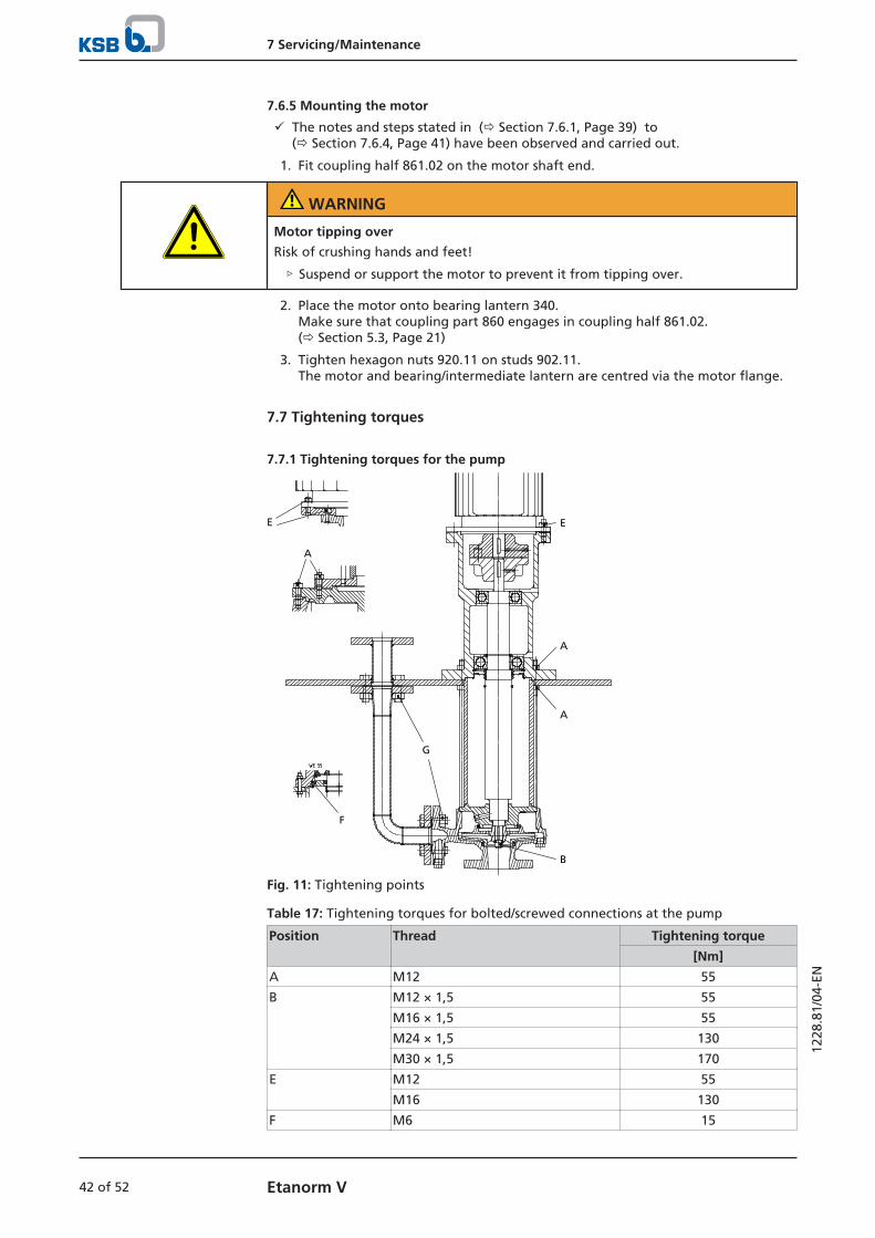
7 Servicing/Maintenance
42 of 52 Etanorm V
1228
.81/
04-E
N
7.6.5 Mounting the motor
ü The notes and steps stated in (ð Section 7.6.1, Page 39) to (ð Section 7.6.4, Page 41) have been observed and carried out.
1. Fit coupling half 861.02 on the motor shaft end.
WARNING
Motor tipping over
Risk of crushing hands and feet!
▷ Suspend or support the motor to prevent it from tipping over.
2. Place the motor onto bearing lantern 340. Make sure that coupling part 860 engages in coupling half 861.02.(ð Section 5.3, Page 21)
3. Tighten hexagon nuts 920.11 on studs 902.11.The motor and bearing/intermediate lantern are centred via the motor flange.
7.7 Tightening torques
7.7.1 Tightening torques for the pump
EE
A
A
A
B
F
G
Fig. 11: Tightening points
Table 17: Tightening torques for bolted/screwed connections at the pump
Position Thread Tightening torque
[Nm]
A M12 55
B M12 × 1,5 55
M16 × 1,5 55
M24 × 1,5 130
M30 × 1,5 170
E M12 55
M16 130
F M6 15
7 Servicing/Maintenance
43 of 52Etanorm V
1228
.81/
04-E
N
Position Thread Tightening torque
[Nm]
G M12 40
M16 100
M20 180
7.8 Spare parts stock
7.8.1 Ordering spare parts
Always quote the following data when ordering replacement or spare parts:
▪ Order number
▪ Order item number
▪ Consecutive number
▪ Type series
▪ Size
▪ Material variant
▪ Seal code
▪ Year of construction
Refer to the name plate for all data. (ð Section 4.3, Page 15)
Also specify the following data:
▪ Part number and description (ð Section 9.1, Page 46)
▪ Quantity of spare parts
▪ Shipping address
▪ Mode of dispatch (freight, mail, express freight, air freight)
7.8.2 Recommended spare parts stock for 2 years' operation to DIN 24296
Table 18: Quantity of spare parts for recommended spare parts stock
Part No. Description Number of pumps (including stand-by pumps)
2 3 4 5 6 - 7 8 - 9 10 andmore
Quantity of spare parts
210 Shaft, complete 1 1 2 2 2 3 30 %
230 Impeller 1 1 2 2 2 3 30 %
321.05/321.06 Radial ball bearing per size 1 1 2 2 2 3 30 %
400.10 Gasket 4 6 8 8 9 12 150 %
411.77 Joint ring 4 6 8 10 12 16 100 %
412.01 O-ring (shaft unit 55) 2 3 4 5 6 7 90 %
421 Lip seal (shaft unit 55) 2 3 4 5 6 8 100 %
502.01/502.02 Casing wear ring 2 2 2 3 3 4 50 %
7.8.3 Sets of spare parts
Table 19: Overview of spare parts sets
Spare parts set Part No. Description
210 - shaft 210 Shaft
550.956) Disc
920.95 Nut
6) For shaft unit 25 only

7 Servicing/Maintenance
44 of 52 Etanorm V
1228
.81/
04-E
N
Spare parts set Part No. Description
210 - shaft 930.95 Safety device
940.01 Key
940.02 Key
102 - volute casing 102 Volute casing
502.01 Casing wear ring
902.017) Stud
903.01 Screw plug
903.03 Screw plug
920.017) Nut
7) For bolted casing cover only
8 Trouble-shooting
45 of 52Etanorm V
1228
.81/
04-E
N
8 Trouble-shooting
WARNING
Improper work to remedy faults
Risk of injury!
▷ For any work performed to remedy faults, observe the relevant informationgiven in this instruction manual and/or in the product literature provided by theaccessories manufacturer.
If problems occur that are not described in the following table, consultation with theKSB service is required.
A Pump delivers insufficient flow rate
B Motor is overloaded
C Increased bearing temperature
D Vibrations during pump operation
Table 20: Trouble-shooting
A B C D Possible cause Remedy8)
✘ - - - Pump delivers against an excessively highpressure.
Re-adjust to duty point.Fit a larger impeller.
✘ - - - Supply line or impeller clogged Remove deposits in the pump and/or piping.
✘ - - ✘ Suction lift is too high/NPSHavailable (positivesuction head) is too low.
Check/alter liquid level.Check any strainers installed/suction opening.
✘ - - - Wrong direction of rotation Interchange two of the phases of the power cable.
✘ - - - Speed is too low.9) Increase speed.
✘ - - ✘ Wear of internal components Replace worn components by new ones.
- ✘ - ✘ Pump back pressure is lower than specified inthe purchase order.
Re-adjust to duty point.In the case of persistent overloading, turn downimpeller.9)
- ✘ - - Density or viscosity of fluid handled higherthan stated in purchase order
Contact KSB.
- - ✘ - Increased axial thrust9) Clean balancing holes in the impeller.Replace the casing wear rings.
- - ✘ ✘ Defective motor deep groove ball bearing Replace.
✘ ✘ - - Motor is running on two phases only. Replace the defective fuse.Check the electric cable connections.
- - - ✘ Rotor out of balance Clean the impeller.Re-balance the impeller.
- - - ✘ Defective plain bearing Replace.
- - - ✘ Flow rate is too low. Increase the minimum flow rate.
8) Pump pressure must be released before attempting to remedy faults on parts which are subjected to pressure.9) Contact KSB.
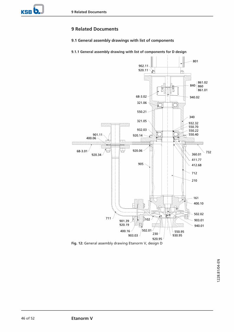
9 Related Documents
46 of 52 Etanorm V
1228
.81/
04-E
N
9 Related Documents
9.1 General assembly drawings with list of components
9.1.1 General assembly drawing with list of components for D design
801
940.02
340
550.21
932.32
210
550.70
321.06
550.40550.22
161
400.10
411.77
502.02
903.01
940.01
902.11920.11
68-3.02
920.14
840
732
905
360.01920.06
412.68
712
711901.39 920.19
400.16903.03
102
502.01230
550.95930.95
920.95
901.11400.06
68-3.01920.34
321.05
932.03
861.02 860 861.01
Fig. 12: General assembly drawing Etanorm V, design D

9 Related Documents
47 of 52Etanorm V
1228
.81/
04-E
N
Table 21: Detail drawings Etanorm V, design D
230
930.95
920.95
Impeller, unbalanced50-32-125.150-32-160.150-32-12565-40-125
Impeller fasteningMaterial variants GG / CC; shaft units WS 35 / 55
902.01
920.01
161
102
Drawing without casing wear ringMaterial variant CC
Bolted casing coverMaterial variants GG / CC; shaft units WS 25 / 35 / 55
500
360.01**
412.01
421
901.36 411.77
902.11
920.11
801
146
914.83
340
Ball bearingMaterial variants GG / CC; ** Only for shaft unit WS 55
Intermediate lantern, for the following shaft units:WS_25: motor 132 / 160 / 180WS_35: motor 132 / 160 / 180 / 200 / 225WS_55: motor 225 (4 poles) / 250 (4 poles) / 280 (4 poles)
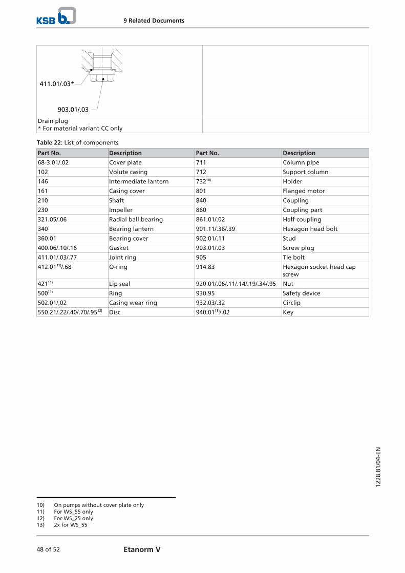
9 Related Documents
48 of 52 Etanorm V
1228
.81/
04-E
N
411.01/.03*
903.01/.03
Drain plug* For material variant CC only
Table 22: List of components
Part No. Description Part No. Description
68-3.01/.02 Cover plate 711 Column pipe
102 Volute casing 712 Support column
146 Intermediate lantern 73210) Holder
161 Casing cover 801 Flanged motor
210 Shaft 840 Coupling
230 Impeller 860 Coupling part
321.05/.06 Radial ball bearing 861.01/.02 Half coupling
340 Bearing lantern 901.11/.36/.39 Hexagon head bolt
360.01 Bearing cover 902.01/.11 Stud
400.06/.10/.16 Gasket 903.01/.03 Screw plug
411.01/.03/.77 Joint ring 905 Tie bolt
412.0111)/.68 O-ring 914.83 Hexagon socket head capscrew
42111) Lip seal 920.01/.06/.11/.14/.19/.34/.95 Nut
50011) Ring 930.95 Safety device
502.01/.02 Casing wear ring 932.03/.32 Circlip
550.21/.22/.40/.70/.9512) Disc 940.0113)/.02 Key
10) On pumps without cover plate only11) For WS_55 only12) For WS_25 only13) 2x for WS_55

10 EU Declaration of Conformity
49 of 52Etanorm V
1228
.81/
04-E
N
10 EU Declaration of Conformity
Manufacturer: KSB SE & Co. KGaAJohann-Klein-Straße 9
67227 Frankenthal (Germany)
The manufacturer herewith declares that the product:
Etabloc, Etabloc SYT, Etaline, Etaline SYT, Etaline Z, Etachrom B,Etachrom L, Etanorm, Etanorm SYT, Etanorm V, Etaprime L,
Etaprime B, Vitachrom
KSB order number: ...................................................................................................
▪ is in conformity with the provisions of the following Directives as amended from time to time:
– Pump (set): Machinery Directive 2006/42/EC
The manufacturer also declares that
▪ the following harmonised international standards have been applied:
– ISO 12100
– EN 809
Person authorised to compile the technical file:
NameFunction Address (company)Address (street, No.)Address (post or ZIP code, city) (country)
The EU Declaration of Conformity was issued in/on:
Place, date
..............................14).............................
Name
Function
CompanyAddress
14) A signed, legally binding EU Declaration of Conformity is supplied with the product.
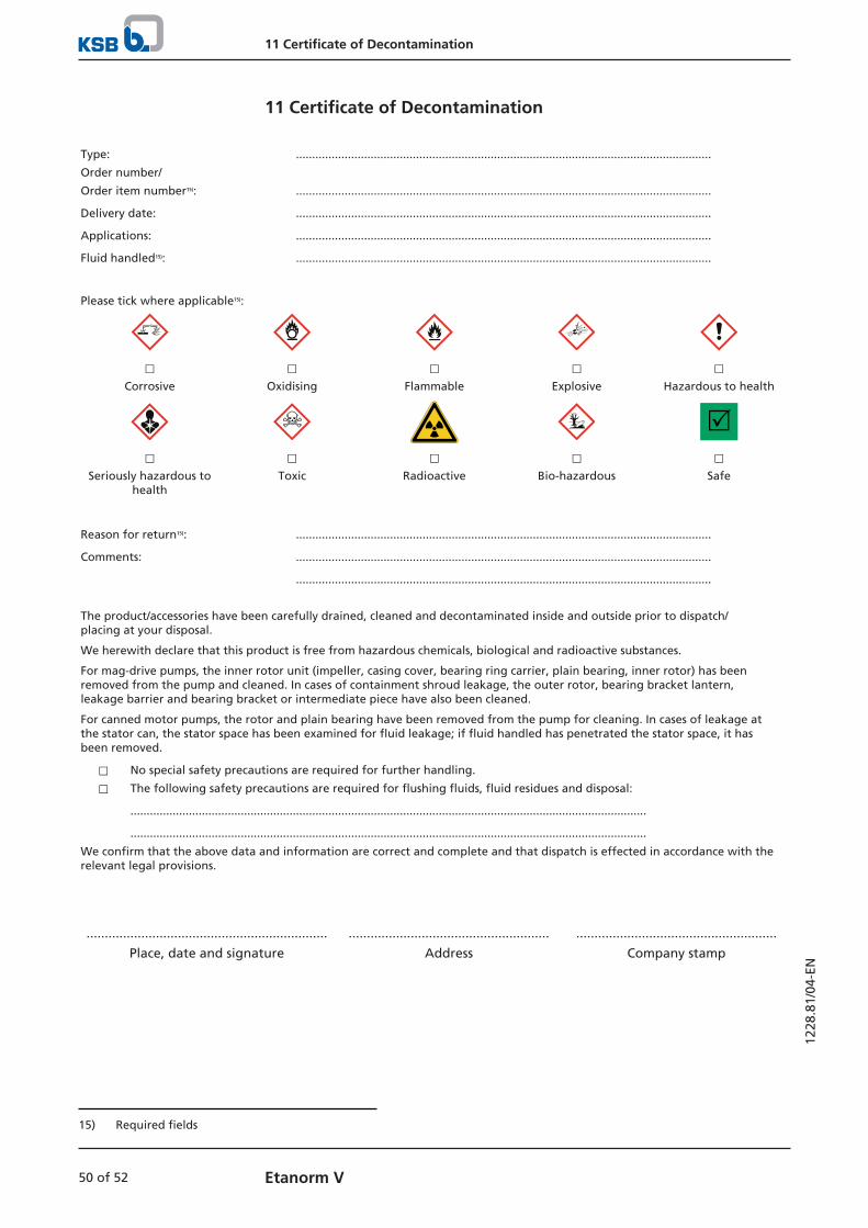
11 Certificate of Decontamination
50 of 52 Etanorm V
1228
.81/
04-E
N
11 Certificate of Decontamination
Type: ................................................................................................................................
Order number/
Order item number15): ................................................................................................................................
Delivery date: ................................................................................................................................
Applications: ................................................................................................................................
Fluid handled15): ................................................................................................................................
Please tick where applicable15):
⃞ ⃞ ⃞ ⃞ ⃞Corrosive Oxidising Flammable Explosive Hazardous to health
R⃞ ⃞ ⃞ ⃞ ⃞
Seriously hazardous tohealth
Toxic Radioactive Bio-hazardous Safe
Reason for return15): ................................................................................................................................
Comments: ................................................................................................................................
................................................................................................................................
The product/accessories have been carefully drained, cleaned and decontaminated inside and outside prior to dispatch/placing at your disposal.
We herewith declare that this product is free from hazardous chemicals, biological and radioactive substances.
For mag-drive pumps, the inner rotor unit (impeller, casing cover, bearing ring carrier, plain bearing, inner rotor) has beenremoved from the pump and cleaned. In cases of containment shroud leakage, the outer rotor, bearing bracket lantern,leakage barrier and bearing bracket or intermediate piece have also been cleaned.
For canned motor pumps, the rotor and plain bearing have been removed from the pump for cleaning. In cases of leakage atthe stator can, the stator space has been examined for fluid leakage; if fluid handled has penetrated the stator space, it hasbeen removed.
⃞ No special safety precautions are required for further handling.
⃞ The following safety precautions are required for flushing fluids, fluid residues and disposal:
...............................................................................................................................................................
...............................................................................................................................................................
We confirm that the above data and information are correct and complete and that dispatch is effected in accordance with therelevant legal provisions.
.................................................................. ....................................................... .......................................................
Place, date and signature Address Company stamp
15) Required fields
Index
51 of 52Etanorm V
1228
.81/
04-E
N
Index
AAutomation 16
BBearing temperature 34
Bearings 16
CCertificate of Decontamination 50
Clearances 34
Commissioning 28
Contact guard 16
Coupling 34
DDesign 16, 17
Direction of rotation 27
Dismantling 37
Disposal 13
Drive 16
EEvent of damage 6
Ordering spare parts 43
Explosion protection 29
FFaults
Causes and remedies 45
Fields of application 8Fluid handled
Density 30
Frequency of starts 30
Function 17
GGrease lubrication
Grease quality 35Intervals 35
IImpeller type 16
Installation 21
Installation at site 21
Intended use 8
KKey to safety symbols/markings 8
NName plate 15
Noise characteristics 18
OOperating limits 29
Order number 6
Other applicable documents 6
PPartly completed machinery 6
Permissible forces at the pump nozzles 25
Piping 24
Preservation 12, 31
Priming and venting 29
Product code 14
Product description 14
Pump casing 16
RReassembly 37, 39
Return to supplier 12
Returning to service 31
SSafety 8
Safety awareness 9
Scope of supply 18
Servicing/Maintenance 33
Shaft seal 16, 28
Shutdown 31Spare part
Ordering spare parts 43
Spare parts stock 43
Start-up 29
Storage 12, 31
TTightening torques 42
Transport 11
WWarnings 8
Warranty claims 6

KSB SE & Co. KGaA
Johann-Klein-Straße 9 • 67227 Frankenthal (Germany)
Tel. +49 6233 86-0
www.ksb.com
1228
.81/
04-E
N(0
1647
931)