vertical high thrust motors · vertical high thrust motors installation, operation, and maintenance...
TRANSCRIPT
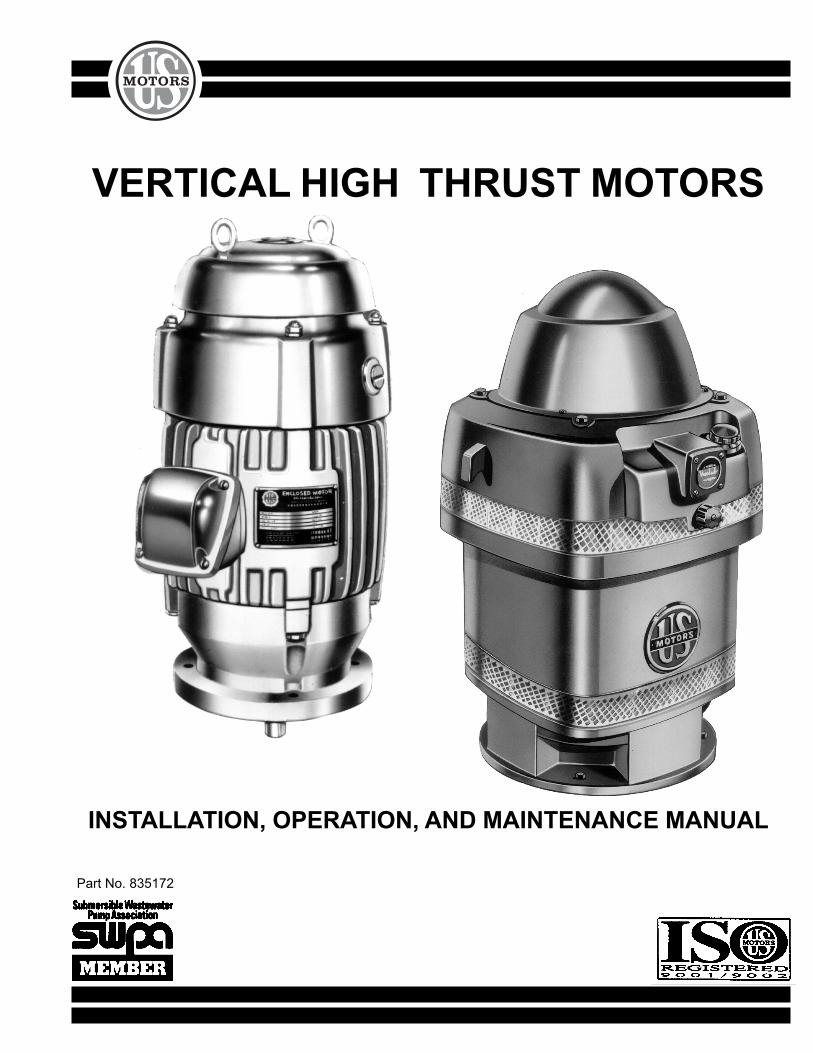
VERTICAL HIGH THRUST MOTORS
INSTALLATION, OPERATION, AND MAINTENANCE MANUAL
Part No. 835172

U.S. ELECTRICAL MOTORSDIVISION OF EMERSON ELECTRIC CO.
U.S. ELECTRICAL MOTORSINSTALLATION AND MAINTENANCE Safety
SAFETY FIRST!
High voltage and rotating parts can cause serious injury or loss of life. Installation, operation, and maintenancemust be performed by qualified personnel. Familiarization with and adherence to NEMA MG2, the NationalElectrical Code, and local codes is recommended. It is important to observe safety precautions to protectpersonnel from possible injury. Personnel should be instructed to:
1. Disconnect all power to motor and accessories prior to initiating any installation, maintenance, or repairs.Also ensure that driven equipment connected to the motor shaft will not cause the motor to rotate (windmillingof fans, water flowing back through pump, etc.).
2. Avoid contact with rotating parts.
3. Act with care in accordance with this manual's prescribed procedures in handling and installing thisequipment.
4. Be sure unit and accessories are electrically grounded and proper electrical installation wiring andcontrols are used in accordance with local and national electrical codes. Refer to "National ElectricalCode Handbook" - NFPA No. 70. Employ qualified electricians.
5. Be sure equipment is properly enclosed to prevent access by children or other unauthorized personnel inorder to prevent possible accidents.
6. Be sure shaft key is fully captive before unit is energized.
7. Provide proper safeguards for personnel against rotating parts and applications involving high inertia loadswhich can cause overspeed.
8. Avoid extended exposure to equipment with high noise levels.
9. Observe good safety habits at all times and use care to avoid injury to yourself or damage to equipment.
10. Be familiar with the equipment and read all instructions thoroughly before installing or working onequipment.
11. Observe all special instructions attached to the equipment. Remove shipping fixtures if so equippedbefore energizing unit.
12. Check motor and driven equipment for proper rotation and phase sequence prior to coupling. Also checkif a unidirectional motor is supplied and note proper rotation.
13. Electric motors can retain a lethal charge even after being shut off. Certain accessories (space heaters,etc.) are normally energized when the motor is turned off. Other accessories such as power factorcorrection capacitors, surge capacitors, etc. can retain an electrical charge after being shut off anddisconnected.
14. Do not apply power correction capacitors to motors rated for operation with variable frequency drives.Serious damage to the drive will result if capacitors are placed between the motor and drive. Consult drivesupplier for further information.

U.S. ELECTRICAL MOTORSDIVISION OF EMERSON ELECTRIC CO.
U.S. ELECTRICAL MOTORSINSTALLATION AND MAINTENANCE Table of Contents
I. SHIPMENT ............................................................................................................................. 1
II. HANDLING ............................................................................................................................. 1
III. STORAGE .............................................................................................................................. 1
IV. INSTALLATION LOCATION.................................................................................................... 5
V. INITIAL INSTALLATION ......................................................................................................... 6
VI. NORMAL OPERATION ......................................................................................................... 10
VII. NON-REVERSE RATCHET ................................................................................................... 11
VIII. END PLAY ADJUSTMENT .................................................................................................... 11
IX. LUBRICATION ....................................................................................................................... 14
X. TROUBLESHOOTING .......................................................................................................... 18
XI. SPARE PARTS ...................................................................................................................... 20
XII. NAMEPLATE & INSTALLATION RECORD ............................................................................ 33
APPENDICESAPPENDIX A "EFFECTS OF UNBALANCED LINE VOLTAGE" ............................................. 35APPENDIX B "MOTORS APPLIED TO VARIABLE FREQUENCY DRIVES" ......................... 36APPENDIX C "ELECTRIC MOTOR LOAD TEST USING THE WATT-HOUR METER" .......... 37

U.S. ELECTRICAL MOTORSDIVISION OF EMERSON ELECTRIC CO.
U.S. ELECTRICAL MOTORSINSTALLATION AND MAINTENANCE
Shipment,Handling &
Storage
1
I. SHIPMENT
Prior to shipment, all motors undergo extensive mechanical and electrical testing, and are thoroughly inspected.Upon receipt of the motor, carefully inspect the unit for any signs of damage that may have occurred duringshipment. Should such damage be evident, unpack the motor at once in the presence of a claims adjuster andimmediately report all damage and breakage to the transportation company.
When contacting U.S. Electrical Motors concerning the motor, be sure to include the complete motor identificationnumber, frame, and type which appear on the nameplate.
II. HANDLING
The equipment needed to handle the motor includes a hoist and spreader bar arrangement (see Figure 1) ofsufficient strength to lift the motor safely. The spreader bar should have the lifting rings or hooks positioned toequal the span of the lifting lugs or eyebolts. The lifting lugs or eyebolts are intended to lift the motor weight only.
WARNINGLifting the motor by other means may result In damage to the motor or injury to personnel.
FIGURE 1
III. STORAGE
1. When To Put A Motor In Storage.
If a motor is not put into immediate service (one month or less), or if it is taken out of service for aprolonged period, special storage precautions should be taken to prevent damage. The following scheduleis recommended as a guide to determine storage needs.
!
U.S. ELECTRICAL MOTORSDIVISION OF EMERSON ELECTRIC CO.
U.S. ELECTRICAL MOTORSINSTALLATION AND MAINTENANCE
Storage
2
A. Out of service or in storage less than one month - no special precautions except that space heaters, ifsupplied, must be energized at any time the motor is not running.
B. Out of service or in storage for more than one month but less than six months - store per items 2A, B,C, D, E, F2, and G, items 3A, B, and C, and item 4.
C. Out of service or in storage for six months or more - all recommendations.
2. Storage Preparation.
A. Where possible, motors should be stored indoors in a clean, dry area.
B. When indoor storage is not possible, the motors must be covered with a tarpaulin. This cover shouldextend to the ground; however, it should not tightly wrap the motor. This will allow the captive air spaceto breathe, minimizing formation of condensation. Care must also be taken to protect the motor fromflooding or from harmful chemical vapors.
CAUTIONImmediately remove any shrink wrap used during shipping. Never wrapany motor in plastic for storage. This can turn the motor into a moisturetrap causing severe, non-warranty damage.
C. Whether indoors or out, the area of storage should be free from excessive ambient vibration which cancause bearing damage.
D. Precautions should be taken to prevent rodents, snakes, birds, or other small animals from nestinginside the motors. In areas where they are prevalent, precautions must be taken to prevent insects,such as dauber wasps, from gaining access to the interior of the motor.
E. Inspect the rust preventative coating on all external machined surfaces, including shaft extensions. Ifnecessary, re-coat the surfaces with a rust preventative material, such as Rust Veto No. 342 (manufac-tured by E.F. Houghton Co.) or an equivalent. The condition of the coating should be checked periodi-cally and surfaces re-coated as needed.
F. Bearings:
(1) When storage time is 6 months or more, grease lubricated cavities must be completely filled withlubricant. Remove the drain plug and fill cavity with grease until grease begins to purge from drainopening. Refer to section IX. "LUBRICATION" and/or review motor’s lubrication nameplate for correctlubricant.
CAUTIONDo not re-grease bearings with drain closed or with unit running.
(2) Oil lubricated motors are shipped without oil. When storage time exceeds one (1) month, the oilsumps must be filled to the maximum capacity as indicated on the oil chamber sight gauge window.Refer to motor lubrication nameplate or Section IX "Lubrication" for proper oil.
!
!

U.S. ELECTRICAL MOTORSDIVISION OF EMERSON ELECTRIC CO.
U.S. ELECTRICAL MOTORSINSTALLATION AND MAINTENANCE
NOTE: Motor must not be moved with oil in reservoir. Drain oil before moving to prevent sloshing and possibledamage. With a clean cloth, wipe any excess oil from the threads of the drain plug and the inside of thedrain hole. Apply Gasoila P/N SS08 or equivalent thread sealant to the threads of the drain plug andreplace the plug in the oil drain hole. Refill oil when motor has been moved to the new location.
G. To prevent moisture accumulation, some form of heating must be utilized. This heating should maintain thewinding temperature at a minimum of 5° above ambient. If space heaters are supplied, they should beenergized. If none are available, single phase or "trickle" heating may be utilized by energizing one phaseof the motor’s winding with a low voltage. Request the required voltage and transformercapacity from U.S. Electrical Motors. A third option is to use an auxiliary heat source and keep the windingwarm by either convection or blowing warm air into the motor.
3. Periodic Maintenance.
A. Oil should be inspected monthly for evidence of moisture or oxidation. The oil must be replacedwhenever contamination is noted or every twelve months; which ever occurs first. It is important to wipeexcess oil from the threads of the drain plug and the drain hole and to coat the plug threads with GasoilaP/N SS08 or equivalent thread sealant before replacing the drain plug.
B. Grease lubricated bearings must be inspected once a month for moisture and oxidation by purging asmall quantity of grease through the drain. If any contamination is present, the grease must becompletely removed and replaced.
C. All motors must have the shaft rotated once a month to maintain a lubricant film on the bearing racesand journals.
D. Insulation History:
The only accurate way to evaluate the condition of the winding insulation is to maintain a history of theinsulation readings. Over a period of months or years these readings will tend to indicate a trend. If adownward trend develops, or if the resistance drops too low, thoroughly clean and dry the windings,retreating if necessary, by an authorized electrical apparatus service shop.
The recommended insulation resistance test is as follows:
(1) Using a megohm meter, with winding at ambient temperature, apply DC voltage (noted below) forsixty seconds and take reading.
Rated Motor Voltage Recommended DC Test VoltageUp to 600 (inclusive) 500 VDC601 to 1000 (inclusive) 500 to 1000 VDC
1001 and up 500 to 2500 VDC(2500 VDC optimum)
Storage
3

U.S. ELECTRICAL MOTORSDIVISION OF EMERSON ELECTRIC CO.
U.S. ELECTRICAL MOTORSINSTALLATION AND MAINTENANCE
(2) For comparison, the reading should be corrected to a 40°C base temperature. This may be done byutilizing the following formula:
R40C = Kt x RtWhere:R40C = insulation resistance (in megohms) corrected to 40°CRt = measured insulation resistance (in megohms)Kt = temperature coefficient (from Graph 1)
INSULATION RESISTANCE TEMPERATURE COEFFICIENT (Kt)
(3) Insulation resistance readings must not drop below the value indicated by the following formula:
Rm = Kv + 1Where:Rm = minimum insulation (in megohms) at 40°CKv = rated motor voltage in kilovolts
(4) Dielectric absorption ratio:
In addition to the individual test reading, a dielectric absorption ratio may be required. The dielectricabsorption ratio is obtained by taking megohm meter readings at a one minute and ten minute interval, orwhen hand powered megohm meters are used, at a thirty second and sixty second interval. The voltageshould be the same as outlined in part 1 of this procedure.
The ratio is obtained by dividing the second reading by the first reading and is based on a goodinsulation system increasing its resistance when subjected to a test voltage for a period of time.
Storage
GRAPH 1
WINDINGTEMPERATURE
(°C)
(Adapted from IEEE 43)
4

U.S. ELECTRICAL MOTORSDIVISION OF EMERSON ELECTRIC CO.
U.S. ELECTRICAL MOTORSINSTALLATION AND MAINTENANCE
10 Minute: 1 Minute 60 Second: 30 SecondDangerous = Less than 1.0 Poor = Less than 1.1
Poor = 1.0 to 1.4 Questionable = 1.1 to 1.24Questionable = 1.5 to 1.9 Fair = 1.25 to 1.3
Fair = 2.0 to 2.9 Good = 1.4 to 1.6Good = 3.0 to 4.0 Excellent = Over 1.6
Excellent = Over 4.0
If a low insulation resistance reading is obtained in either the individual test or dielectric absorp-tion ratio test, thoroughly clean and dry the windings. Recheck insulation resistance and dielec-tric absorption ratio.
NOTE: Slightly lower dielectric absorption ratios may be acceptable when high initial insulation resis-tance readings are obtained (1000 + megohms). Refer any questions to USEM Product ServiceDepartment.
For additional information on insulation testing, refer to IEEE Transaction No. 43.
4. Start-up Preparations After Storage.
A. Motor should be thoroughly inspected and cleaned to restore to an “As Shipped" condition.
B. Motors which have been subjected to vibration must be disassembled and each bearing inspectedfor damage.
C. When storage time has been six (6) months or more, oil and/or grease must be completely changedusing lubricants and methods recommended on the motor’s lubrication plate, or in Section IX -"LUBRICATION."
D. The winding must be tested to obtain insulation resistance and dielectric absorption ratio as de-scribed in Section III., item 3.
E. Contact USEM Product Service Department prior to start-up if storage time has exceeded one year.
IV. INSTALLATION LOCATION
When selecting a location for the motor and driven unit, keep the following items in mind:
1. The location should be clean, dry, well ventilated, properly drained, and provide accessibility for inspec-tion, lubrication, and maintenance. Outdoor installations on open dripproof motors require protectionfrom the elements.
2. The location should provide adequate space for motor removal without shifting the driven unit.
3. Temperature rise of a standard motor is based upon operation at an altitude not exceeding 3300 feet (1000meters) above sea level unless specified otherwise on nameplate.
Storage &InstallationLocation
5
U.S. ELECTRICAL MOTORSDIVISION OF EMERSON ELECTRIC CO.
U.S. ELECTRICAL MOTORSINSTALLATION AND MAINTENANCE
4. To avoid condensation inside the motor, it should not be stored or operated in areas subject to rapidtemperature changes unless it is energized or protected by space heaters.
5. The motor should not be installed in close proximity to any combustible material or where flammablegases may be present, unless it is specifically built for that environment and is U.L. labeled accordingly.
6. Oil lubricated motors must be mounted within one degree of true vertical. Failure to do so will result in oilleakage and possibly bearing failure.
V. INITIAL INSTALLATION
1. General
Reliable, trouble free operation of a motor and driven unit depends on a properly designed foundation andbase plus good alignment. If the motor and driven unit are not installed properly, the following may result:
* Noisy operation * Excessive vibration* Bearing damage or failure * Motor failure
2. Shaft Alignment
On Holloshaft motors, the pump shaft and motor coupling must be aligned within .003" TIR. On Solidshaftmotors, the motor and pump shafts must be aligned within .002" TIR.
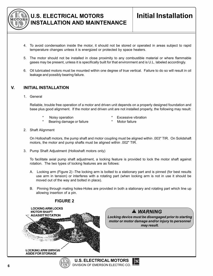
3. Pump Shaft Adjustment (Holloshaft motors only)
To facilitate axial pump shaft adjustment, a locking feature is provided to lock the motor shaft againstrotation. The two types of locking features are as follows:
A. Locking arm (Figure 2) -The locking arm is bolted to a stationary part and is pinned (for best resultsuse arm in tension) or interferes with a rotating part (when locking arm is not in use it should bemoved out of the way and bolted in place).
B. Pinning through mating holes-Holes are provided in both a stationary and rotating part which line upallowing insertion of a pin.
Initial Installation
FIGURE 2
6
LOCKING ARM LOCKS
ASIDE FOR STORAGE
WARNINGLocking device must be disengaged prior to startingmotor or motor damage and/or injury to personnel
may result.
!

U.S. ELECTRICAL MOTORSDIVISION OF EMERSON ELECTRIC CO.
U.S. ELECTRICAL MOTORSINSTALLATION AND MAINTENANCE
CAUTIONCare should be exercised when lowering the motor over the pump shaft so that the oil retainingtube in the lower bracket is not damaged (applies only to motors with oil lubricated lower bearing).
4. Drive Coupling (Holloshaft units only).
The drive coupling may be utilized in one of two ways:
A. Bolted type (Figure 3) - Hold down bolts are installed (some motors require removal of driving pins toallow installation of hold down bolts) in the drive coupling to prevent upward movement of the pumpshaft. This will allow momentary upthrust from the pump to be taken by the motor's guide bearing.
WARNINGFailure to tighten coupling and non-reverse ratchet bolts to required torque values may cause boltsto break, resulting in equipment damage or injury to personnel.
B. Self-release type (Figure 4) - Driving pins are used to engage the drive coupling with the rotor. Apower reversal may unscrew the joints of the pump shafting, causing the shafting to lengthen andbuckle or break if the shafting is restrained. The self-release coupling will lift out of engagement withpartial unscrewing of the shafting, thus stopping further rotation of the pump. The following items mustbe followed for proper functioning of the self-release coupling:
• The pump shaft adjusting nut must be properly secured to the drive coupling with a locking screw.• The drive coupling should not bind on the driving pins.• The drive coupling must not be bolted down.• The pump shaft must be concentric to the motor shaft to prevent rubbing of the pump shaft inside
the motor shaft.• There must be no potential for upthrust in the application.• Do not use the self-release feature in conjunction with a lower steady bushing, as friction between
the parts can damage the line shafting and/or bushing.• Due to the possibility of sparking as the parts separate, the self-release feature must not be used
in an environment where explosive gases may be present.
Initial Installation
7
DRIVECOUPLING
BOLTED COUPLINGFIGURE 3
SELF RELEASE COUPLINGFIGURE 4
ADJUSTING NUT LOCKING SCREW
ENGAGED DISENGAGED
!
!

U.S. ELECTRICAL MOTORSDIVISION OF EMERSON ELECTRIC CO.
U.S. ELECTRICAL MOTORSINSTALLATION AND MAINTENANCE
WARNINGShould a motor supplied with a self-release coupling become uncoupled, the motor andpump must be stationary and all power locked out before manually re-coupling.
5. Water Cooling For Bearing Oil Reservoir.
If the motor is equipped with cooling coils in the oil reservoir, a minimum water supply of 4 GPM must bemaintained at a maximum of 125 PSI with a 32°C (90°F) maximum inlet temperature. External waterconnections must be self draining to prevent cooling coil rupture at freezing temperatures. Use clean,noncorrosive water only. If corrosive conditions exist and are specified at time of motor order, specialcorrosion resistant fittings can be supplied.
6. Electrical Connection.
Refer to the motor nameplate for power supply requirements and to the connection diagram on the motor.Be sure connections are tight. Check carefully and assure that they agree with the connection diagram,then carefully tape all connections with electrical tape to be sure that they will not short against each otheror to ground. Be sure the motor is grounded to guard against possible electrical shock. Refer to theNational Electrical Code Handbook (NFPA No. 70) and to local electrical codes for proper wiring, protection,and wire sizing. Be sure proper starting equipment and protective devices are used for every motor. Forassistance contact the local sales office of the motor starter manufacturer for the particular brand ofequipment you are using.
Part Winding Starters: Part winding starters used with part winding start motors should have the timer setat a minimum time consistent with the power company requirements. The recommended maximum time onpart winding is two seconds. Setting the timer for longer periods can cause permanent damage to the motorand may void the warranty. Note that motor may or may not start on part winding start connection.
7. Direction Of Rotation.
As a standard, motors that are equipped with a non-reverse ratchet are designed to operate in a counter-clockwise direction as viewed from the top of the motor. Also, some high speed motors have unidirectionalventilating fans. When the motor has a unidirectional ventilating fan, the direction of rotation is indicated byan arrow mounted on the motor and by a warning plate mounted near the main nameplate.
CAUTIONApply power momentarily to observe the direction of rotation for which the leads areconnected. Motor damage may occur if power is applied for more than ten seconds whilerotation is locked against the non-reverse ratchet. The motor should be uncoupled fromthe driven equipment during this procedure to assure driven equipment is not damagedby reverse rotation. Couplings (if installed) should be properly secured.
To reverse direction of rotation (if motor is not operating in the correct direction) inter-change any two of the three power leads on the motor. Be sure the power is off and stepsare taken to prevent accidental starting of the motor before attempting to change electri-cal connection.
Initial Installation
8
!
!

U.S. ELECTRICAL MOTORSDIVISION OF EMERSON ELECTRIC CO.
U.S. ELECTRICAL MOTORSINSTALLATION AND MAINTENANCE
8. Spring-Preloaded Thrust Bearings.
Motors built with spherical roller thrust bearings (bearing number 29xxx) at any speed or tandem angularcontact thrust bearings (bearing number 7xxx) on large 3600 or 3000 RPM (2-pole) motors have preloadsprings which maintain a minimum thrust load at all times to prevent bearing skidding. These motorsrequire a minimum external thrust load sufficient to compress the springs to properly seat the thrustbearing and to relieve the lower guide bearing of axial spring thrust. Refer to motor’s minimum thrustnameplate for required thrust.
CAUTIONDo not run a motor which has bearing preload springs without thrust load formore than fifteen (15) minutes as bearing damage may result.
9. Initial Start.
After installation is completed, but before motor is put into regular service, make an initial start as follows:
A. Ensure that motor and control device connections agree with wiring diagrams.
B. Ensure that voltage, phase, and frequency of line circuit (power supply) agree with motor nameplate.
C. Check insulation resistance according to Section III "STORAGE" item 3.
D. Check all foundation, base, non-reverse ratchet (if applicable), and coupling bolts (if applicable) toensure they are tight.
E. If motor has been in storage, either before or after installation, refer to Section III "STORAGE" item 4 forpreparations.
F. Check oil lubricated units to be certain that bearing housings have been filled to between the "MAX"and "MIN" levels on the sight gauge windows with the correct lubricant. Refer to Section IX"LUBRICATION" for proper oils.
G. Check for proper or desired rotation. See item 7 of this section for details.
H. Ensure that all protective devices are connected and operating properly, and that all outlet accessory,and access covers have been returned to their original intended position.
I. Start motor at lowest possible load and monitor to be sure that no unusual condition develops.
WARNINGAll loosened or removed parts must be reassembled and tightened to originalspecifications. Keep all tools, chains, equipment, etc. clear of unit before ener-gizing motor.
J. When checks are satisfactory to this point, increase load slowly up to rated load and monitor unit forsatisfactory operation.
Initial Installation
9
!
!

U.S. ELECTRICAL MOTORSDIVISION OF EMERSON ELECTRIC CO.
U.S. ELECTRICAL MOTORSINSTALLATION AND MAINTENANCE
VI. NORMAL OPERATION
Start the motor in accordance with standard instructions for the starting equipment used.
1. General Maintenance.
Regular, routine maintenance is the best assurance of trouble-free, long-life motor operation. It preventscostly shutdown and repairs. Major elements of a controlled maintenance program are:
A. Trained personnel who have a working knowledge of rotational equipment and have read this manual.
B. Systematic records which contain at least the following:
1. Complete nameplate data.2. Prints (wiring diagrams, certified outline dimensions).3. Alignment data.4. Results of regular inspection, including vibration and bearing temperature data, as applicable.5. Documentation of any repairs.6. Lubrication data:
- Method of application- Types of lubricants for wet, dry, hot, or adverse locations- Maintenance cycle by location (some require more frequent lubrication)
2. Inspection and Cleaning
Stop the motor before cleaning. CAUTION: Assure against accidental starting of the motor. Clean themotor inside and out regularly. The frequency of cleaning depends upon actual conditions existing aroundthe motor. Use the following procedures as they apply:
A. Wipe off dirt, dust, oil, water, or other liquids from external surfaces of motor. These materials canwork into or be carried into the motor windings and may cause overheating or insulation breakdown.
B. Remove dirt, dust, or debris from ventilating air inlets. Never allow dirt to accumulate near air inlets.Never operate motor with air passages blocked.
C. Clean motors internally by blowing with clean, dry, compressed air at 40 to 60 PSI. If conditionswarrant, use a vacuum cleaner.
CAUTIONWhen using compressed air, always use proper eye protection to prevent accidental eye injury.
D. When dirt and dust are solidly packed, or windings are coated with oil or greasy grime, disassemblethe motor and clean with solvent. Use only high-flash naphtha, mineral spirits, or Stoddard solvent.Wipe with solvent dampened cloth, or use suitable soft bristled brush. DO NOT SOAK. Oven dry(150 – 175°F) solvent cleaned windings thoroughly before reassembly.
E. After cleaning and drying the windings, check the insulation resistance per Section III, Item 3.
Normal Operation
10
!

U.S. ELECTRICAL MOTORSDIVISION OF EMERSON ELECTRIC CO.
U.S. ELECTRICAL MOTORSINSTALLATION AND MAINTENANCE
VII. NON-REVERSE RATCHET
Units featuring non-reverse ratchets are refine-balanced by attaching weights to the rotating ratchet. If theratchet is removed it should be marked and reassembled in the same position to retain proper balance.
VIII. ENDPLAY ADJUSTMENT
The term endplay is defined as the total axial float of the rotor. Should the motor be disassembled for anyreason, the rotor endplay must be adjusted. Care must be taken to ensure that end play is within the properrange. Use one of the following procedures, depending upon the type of thrust bearing to set end play:
CAUTIONExcessive endplay can allow the thrust bearing to separate when units are run withzero thrust or momentary up thrust, resulting in thrust bearing failure. Insufficientendplay may cause the bearings to load against each other, resulting in extreme heatand rapid failure of both the guide and thrust bearings.
1. Spherical Roller Thrust Bearings and Angular Contact Bearings (With Springs).
Setting the correct end play on units with spring-preloaded spherical roller or angular contact thrustbearings requires a controlled assembly method, due to various deflections internal to the motor andfriction of locknut threads from spring force. An end play setting of .005 to .008 inches is required to allowthe lower guide bearing to return to an unloaded position when external thrust is applied to the motor (seeFigure 5). End play can be properly adjusted by the following recommended procedure:
A. Place spring retainer (without springs) and lower thrust washer of bearing into upper bearing bore.
B. Using a depth micrometer, measure the distance between the top of the lower thrust washer and thefaced surface on top of the bearing housing (see Figure 5). Record dimension to three decimals.
C. Add .005 to .008 inches to the recorded dimension to obtain the correct endplay range for the unit.
D. Reassemble bearing with springs. Motor is now ready to set end play. Several acceptable methodsfor setting endplay are following.
NOTE: Certain motor builds require removal of the fabricated steel or cast aluminum oil baffle toprovide access for depth micrometer measurements.
FIGURE 5SPHERICAL ROLLER THRUST BEARING ANGULAR CONTACT BEARING
Spring Spring
End PlayAdjustment
Depth micrometer shows theincreased height from theprevious solid height reading.
Bearing raised .005" to .008"in final position.
Depth micrometer shows theincreased height from theprevious solid height reading.
Bearing raised .005" to.008" in final position.
11
!

U.S. ELECTRICAL MOTORSDIVISION OF EMERSON ELECTRIC CO.
U.S. ELECTRICAL MOTORSINSTALLATION AND MAINTENANCE
2. Angular Contact Ball Bearings (Without Springs)
A. No preliminary measurements are required to set end play. End play may be set by any of thefollowing methods described in this section.
B. To correctly adjust the endplay setting, a dial indicator should be positioned to read the shaft axialmovement. (See figure 7 for location of dial indicator). The rotor adjusting lock nut should be turneduntil no further upward movement of the shaft is indicated. The locknut is then loosened until .005 to.008" endplay is obtained. Lock the locknut with lock washer.
CAUTIONCare should be taken to ensure that the locknut is not over-tightened, as this can lead to anerroneous end play setting (due to deflection of parts) and bearing damage may result.
C. Motors that have two opposed angular contact bearings that are locked for up and downthrust do notrequire endplay adjustment. The shaft, however, must be set to the original ‘AH’ (shaft extensionlength) to prevent the guide bearing from taking thrust.
ENDPLAY ADJUSTMENT METHODS
1. Method 1 (refer to Figures 6 & 7)
This method requires the user to install a bolted chain from the bearing mount back to a lifting lug. Rotatethe locknut with a spanner wrench (and bar extension) until dial indicator shows no movement on end ofshaft. The locknut should then be loosened until proper endplay is obtained, lock the locknut with lockwasher. (See figure 7 for location of dial indicator.)
NOTE: This is the lowest cost of the three methods and requires the least amount of equipment. Thismethod, however, may be less desirable than Method 2 as considerable locknut torque may be encoun-tered on units with bearing preload springs.
Special equipment required: • Locking bolts • Dial indicator• 3/4" chain • Depth micrometer• Spanner wrench with extension
FIGURE 6 (METHOD 1) FIGURE 7 (METHOD 1 & 3)
MUST REST ONEND OF SHAFT
MOUNTING SPRINGS ARE COMPRESSED ANDROTOR IS LIFTED BY LOCKNUT
DIAL INDICATORBASE MUST RESTON A STATIONARY PARTAS CLOSE AS POSSIBLE TO SHAFT.
DIAL INDICATOR SHOWSMOVEMENT OF SHAFT
End PlayAdjustment
12
!

U.S. ELECTRICAL MOTORSDIVISION OF EMERSON ELECTRIC CO.
U.S. ELECTRICAL MOTORSINSTALLATION AND MAINTENANCE
2. Method 2 (refer to Figure 8 - Utilized on Spring Loaded Bearings Only)
This method utilizes a spreader bar and chains to wrap around lifting lugs, a hydraulic jack (five ton), andcrane to lift the spreader bar. The hydraulic jack is supported by two steel blocks of equal thickness on topof the bearing mounting with the jack pushing against the spreader bar. On large motors, the rotor can belifted by placing a second jack below the motor shaft to allow the locknut to be turned easily.
NOTE: This method utilizes typical shop equipment and tools. Endplay settings can be checked quicklyon larger vertical motor products. The locknut lifts rotor weight only.
Equipment required: • Large spreader bar with chains and locking bolts• Overhead crane • Depth micrometer • Spanner wrench• Metal blocks • 5-ton hydraulic jack • Dial indicator
FIGURE 8 (METHOD 2)
3. Method 3 (refer to Figure 9)
This method uses a one inch thick steel disc with a center hole for the shaft end bolt and two threadedhydraulic jacks connected to a single pump. Apply load to hydraulic jacks until dial indicator shows nomovement on end of shaft. (See figure 7 for location of dial indicator). The shaft locknut should bepositioned and the pressure from hydraulic jack relieved until proper endplay is obtained.
CAUTIONUse of excessive hydraulic pressure can damage bearings.
NOTE: This method is directly usable on solid shaft motors and can be used on most HOLLOSHAFTmotors with the use of a long threaded rod and plate. It is easy to apply and settings can be checkedquickly, especially in field service. The locknut does not see any force and can be turned easily.
Equipment required: • Fixture with hydraulic jacks • Dial indicator • Spanner wrench
CAUTIONAfter setting endplay, run unit for three to five minutes, then stop and verify the endplay setting. Readjustas necessary. All loosened or removed parts must be reassembled and tightened to original specifica-tions. Keep all tools, chains, equipment, etc. clear of unit before energizing motor.
MOUNTING SPRINGS ARECOMPRESSED – ONLY THEROTOR IS LIFTED BY THELOCKNUT.
SPREADER BAR
HYDRAULIC JACK
End PlayAdjustment
FIGURE 9 (METHOD 3) HYDRAULIC PUMP
PLATE BOLTED TO SHAFT
JACKS
MOUNTING SPRINGS ARE COM-PRESSED AND ROTOR IS LIFTEDBY THE FIXTURE. THE LOCKNUT ISTURNED FOR ADJUSTMENT.
13
!
!

U.S. ELECTRICAL MOTORSDIVISION OF EMERSON ELECTRIC CO.
U.S. ELECTRICAL MOTORSINSTALLATION AND MAINTENANCE
!
!
!
Lubrication
14
IX. LUBRICATION
Motor must be at rest and electrical controls should be locked open to prevent energizing while beingserviced. If motor is being taken out of storage refer to Section III “STORAGE”, item 4 for instructions.
1. Oil Lubricated Bearings.
Change oil once per year with normal service conditions. Frequent starting and stopping, damp or dustyenvironment, extreme temperature, or any other severe service conditions will warrant more frequent oilchanges. If there is any question, consult U.S. Electrical Motors Product Service Department for recom-mended oil change intervals regarding your particular situation.
Determine required oil ISO Viscosity Grade (VG) and base oil type from Table 3, then see Table 4 for approvedoils. Add oil into oil fill hole at each bearing housing until the oil level reaches between minimum and maxi-mum marks located on the sight gauge window. It is important to wipe excess oil from the threads of the drainhole and to coat the plug threads with Gasoila P/N SS08, manufactured by Federal Process Corporation orequivalent thread sealant before replacing the drain plug. Plug should be tightened to a minimum of 20 lb.-ft.using a torque wrench. See the motor nameplate or Table 5 for the approximate quantity of oil required.
2. Grease Lubricated Bearings.
A. Relubrication of Units in Service
Grease lubricated bearings are pre-lubricated at the factory and normally do not require initial lubri-cation. Relubricating interval depends upon speed, type of bearing and service. Refer to Table 1 forsuggested regreasing intervals and quantities. Note that operating environment and application maydictate more frequent lubrication.
To relubricate bearings, remove the drain plug. Inspect grease drain and remove any blockage(caked grease or foreign particles) with a mechanical probe, taking care not to damage bearing.
WARNINGUnder NO circumstances should a mechanical probe be used while the motor is in operation.
Add new grease at the grease inlet. New grease must be compatible with the grease already in the motor(refer to table 2 for compatible greases).
CAUTIONGreases of different bases (lithium, polyurea, clay, etc.) may not be compatible when mixed. Mixingsuch greases can result in reduced lubricant life and premature bearing failure. Prevent such inter-mixing by disassembling motor, removing all old grease and repacking with new grease per item B ofthis section. Refer to Table 2 for recommended greases.
Run the motor for 15 to 30 minutes with the drain plug removed to allow purging of any excessgrease. Shut off unit and replace the drain plug. Return motor to service.
CAUTIONOvergreasing can cause excessive bearing temperatures, premature lubricant breakdown and bearingfailure. Care should be exercised against overgreasing.

U.S. ELECTRICAL MOTORSDIVISION OF EMERSON ELECTRIC CO.
U.S. ELECTRICAL MOTORSINSTALLATION AND MAINTENANCE
B. Change of Lubricant
Motor must be disassembled as necessary to gain full access to bearing housing(s).
Remove all old grease from bearings and housings (including all grease fill and drain holes). Inspect andreplace damaged bearings. Fill bearing housings both inboard and outboard of bearing approximately 30percent full of new grease. Grease fill ports must be completely charged with new grease. Inject newgrease into bearing between rolling elements to fill bearing. Remove excess grease extending beyond theedges of the bearing races and retainers.
Table 1Recommended Grease Replenishment Quantities & Lubrication Intervals
Refer to motor nameplate for bearings provided on a specific motor.
For bearings not listed in Table 1, the amount of grease required may be calculated by the formula:
G = 0.11 x D x B
Where: G = Quantity of grease in fluid ounces.D = Outside diameter of bearing in inches.B = Width of bearing in inches.
Table 2Recommended Greases
The above greases are interchangeable with the grease provided in units supplied from the factory (unlessstated otherwise on motor lubrication nameplate).
15
Lubrication
rebmuNgniraeB esaerG esaerG esaerG esaerG esaerGtnemhsinelpeR
ytitnauQ).zO.lF(
lavretnInoitacirbuL lavretnInoitacirbuL lavretnInoitacirbuL lavretnInoitacirbuL lavretnInoitacirbuL
xx27,xx26 xx27,xx26 xx27,xx26 xx27,xx26 xx27,xx26 xx37,xx36 xx37,xx36 xx37,xx36 xx37,xx36 xx37,xx36 0063urht1081 0063urht1081 0063urht1081 0063urht1081 0063urht1081MPR
0081urht1021 0081urht1021 0081urht1021 0081urht1021 0081urht1021MPR
dnaMPR0021 dnaMPR0021 dnaMPR0021 dnaMPR0021 dnaMPR0021rewols
70urht30 60urht30 2.0 raeY1 sraeY2 sraeY2
21urht80 90urht70 4.0 shtnoM6 raeY1 raeY1
51urht31 11urht01 6.0 shtnoM6 raeY1 raeY1
02urht61 51urht21 0.1 shtnoM3 shtnoM6 shtnoM6
82urht12 02urht61 8.1 shtnoM3 shtnoM6 shtnoM6
eziSemarFrotoM eziSemarFrotoM eziSemarFrotoM eziSemarFrotoM eziSemarFrotoM erusolcnErotoM erusolcnErotoM erusolcnErotoM erusolcnErotoM erusolcnErotoM esaerG esaerG esaerG esaerG esaerGrerutcafunaM
esaerG esaerG esaerG esaerG esaerG)2edarGIGLN(
744urhTllA llA srotoMlacirtcelESU.cnI,ASUnorvehC
ASU.oCnoxxE
34338.oNesaerG2.oNIRSME-xeryloPpUdna944 foorppirDnepO
pUdna944 dnaCFETfoorpnoisolpxE
srotoMlacirtcelESU.oCliOliboM
024479.oNesaerG001-CHShtiliboM

U.S. ELECTRICAL MOTORSDIVISION OF EMERSON ELECTRIC CO.
U.S. ELECTRICAL MOTORSINSTALLATION AND MAINTENANCE
Table 3US Motors Recommended Oil Viscosities
Lubrication
16
Notes:1.If lower guide bearing is oil lubricated, it should use the same oil as the thrust bearing.2.If lower guide bearing is grease-lubricated, refer to TABLE 2 for recommended greases.3.Refer to US Electrical Motors for ambient temperatures other than those listed.
)seireSXX37roXX27(gniraeBtsurhTtcatnoCralugnA )seireSXX37roXX27(gniraeBtsurhTtcatnoCralugnA )seireSXX37roXX27(gniraeBtsurhTtcatnoCralugnA )seireSXX37roXX27(gniraeBtsurhTtcatnoCralugnA )seireSXX37roXX27(gniraeBtsurhTtcatnoCralugnA
erusolcnErotoM erusolcnErotoM erusolcnErotoM erusolcnErotoM erusolcnErotoM eziSemarF eziSemarF eziSemarF eziSemarF eziSemarF )MPR(deepS )MPR(deepS )MPR(deepS )MPR(deepS )MPR(deepS erutarepmeTtneibmA erutarepmeTtneibmA erutarepmeTtneibmA erutarepmeTtneibmA erutarepmeTtneibmA GVOSI GVOSI GVOSI GVOSI GVOSI epyTliOesaB epyTliOesaB epyTliOesaB epyTliOesaB epyTliOesaB
rofoorppirDnepOdetcetorPrehtaeW regraLdna423
llA
)F401(C04urhtpU 23 citehtnySrolareniM
)F221-501(C05urhtC14 86 ylnOcitehtnyS
desolcnEyllatoTfoorpnoisolpxEro
744urht404)F401(C04urhtpU 23 citehtnySrolareniM
)F221-501(C05urhtC14 86 ylnOcitehtnyS
1185urht944
0063-1081)F401(C04urhtpU
23 ylnOcitehtnyS
woleB&0081 86 ylnOcitehtnyS
llA )F221-501(C05urhtC14 eciffOotrefeR
)seireSXXX92(gniraeBtsurhTrelloRlacirehpS )seireSXXX92(gniraeBtsurhTrelloRlacirehpS )seireSXXX92(gniraeBtsurhTrelloRlacirehpS )seireSXXX92(gniraeBtsurhTrelloRlacirehpS )seireSXXX92(gniraeBtsurhTrelloRlacirehpS
erusolcnErotoM erusolcnErotoM erusolcnErotoM erusolcnErotoM erusolcnErotoM eziSemarF eziSemarF eziSemarF eziSemarF eziSemarF )MPR(deepS )MPR(deepS )MPR(deepS )MPR(deepS )MPR(deepS erutarepmeTtneibmA erutarepmeTtneibmA erutarepmeTtneibmA erutarepmeTtneibmA erutarepmeTtneibmA GVOSI GVOSI GVOSI GVOSI GVOSI epyTliOesaB epyTliOesaB epyTliOesaB epyTliOesaB epyTliOesaB
rofoorppirDnepOdetcetorPrehtaeW regraLdna444
dna0081woleB
)F14-5(C5urhtC51- 86citehtnySrolareniM
)F401-24(C04urhtC6051
)F221-501(C05urhtC14 ylnOcitehtnyS
desolcnEyllatoTfoorpnoisolpxEro regraLdna944
)F14-5(C5urhtC51- 86 citehtnySrolareniM
)F401-24(C04urhtC6 051 ylnOcitehtnyS
)F221-501(C05urhtC14 eciffOotrefeR
rerutcafunaMliO rerutcafunaMliO rerutcafunaMliO rerutcafunaMliO rerutcafunaMliO
23GVOSI 23GVOSI 23GVOSI 23GVOSI 23GVOSI 86GVOSI 86GVOSI 86GVOSI 86GVOSI 86GVOSI 051GVOSI 051GVOSI 051GVOSI 051GVOSI 051GVOSI
F001@USS561-031:ytisocsiV F001@USS561-031:ytisocsiV F001@USS561-031:ytisocsiV F001@USS561-031:ytisocsiV F001@USS561-031:ytisocsiV F001@USS743-482:ytisocsiV F001@USS743-482:ytisocsiV F001@USS743-482:ytisocsiV F001@USS743-482:ytisocsiV F001@USS743-482:ytisocsiV F001@USS567-026:ytisocsiV F001@USS567-026:ytisocsiV F001@USS567-026:ytisocsiV F001@USS567-026:ytisocsiV F001@USS567-026:ytisocsiV
liOesaBlareniM liOesaBlareniM liOesaBlareniM liOesaBlareniM liOesaBlareniM liOesaBcitehtnyS liOesaBcitehtnyS liOesaBcitehtnyS liOesaBcitehtnyS liOesaBcitehtnyS liOesaBlareniM liOesaBlareniM liOesaBlareniM liOesaBlareniM liOesaBlareniM liOesaBcitehtnyS liOesaBcitehtnyS liOesaBcitehtnyS liOesaBcitehtnyS liOesaBcitehtnyS liOesaBlareniM liOesaBlareniM liOesaBlareniM liOesaBlareniM liOesaBlareniM liOesaBcitehtnyS liOesaBcitehtnyS liOesaBcitehtnyS liOesaBcitehtnyS liOesaBcitehtnyS
cnI,ASUnorvehC 23liOenibruTTSG 23argeT 86liOenibruTTSG 86argeT liOenihcaMO&R051 051argeT
.oCliOoconoC raelcordyH23liOenibruT 23nocnyS raelcordyH
86liOenibruT 86nocnyS .dyHWAraelcordyH051diulF A/N
ASU,.oCnoxxE 23citssereT 23citsennyS 86citssereT 86citsennyS 051citssereT 051citsennyS
.oCliOliboM thgiLliOETD 426CHS yvaeHliOETDmuideM 626CHS artxEliOETD
yvaeH 926CHS
cnI,.oClioznneP 23OTllebznneP 23DHSllebznneP 86OTllebznneP 86DHSllebznneP 051OTllebznneP 051DHSllebznneP
.oCmuelortePspillihP 23sungaM 23"E"lairtsudnyS 86sungaM 86"E"lairtsudnyS 051sungaM A/N
.oCliOllehS 23sulleT liODHsulleT23FHSWA 86sulleT liODHsulleT
86FHSWA 051sulleT A/N
.oCstnacirbuLocaxeT 23lageR 23OAPsuteC 86lageR 86OAPsuteC 051lageR A/N
Table 4US Motors Approved Oil Specifications For Use With Anti-Friction Bearings

U.S. ELECTRICAL MOTORSDIVISION OF EMERSON ELECTRIC CO.
U.S. ELECTRICAL MOTORSINSTALLATION AND MAINTENANCE
Lower Bearing
Grease
5343
Grease6
Grease13
Grease
Upper Bearing
Grease
351764
Grease
6522
GreaseGrease
122022243770
Grease70
Grease64
Grease
Table 5Approximate Oil Sump Capacities
Frame Size
180 - 280180 - 280320 - 440320 - 360
400440
180 - 440180 -360
400440449
5000
5800
6800
8000
9600
Oil Capacity (Quarts)Motor Type Designation(See Motor Nameplate)
AU, AV-4AVRVRV-4, RURV-4, RURV-4 (2 pole)RV-4, RU (4 pole & slower, w/ ang contact thrust brg.)
(4 pole & slower, w/ spherical thrust brg.)TV-9, TV, LV-9, LVTV-4, TU, LV-4, LUTV-4, TU, LV-4, LUTV-4, TU, LV-4, LUJU, JV-4, HU, HV-4JV-3, JV, HVHV, EV, JVHU, HV-4 (4 pole & slower)HV-4 (2 pole only)EU, JU, EV-4, JV-4HU, HV-4EU, JU, EV-4, JV-4HU, HV-4HVRU, RV-4RVRU, RV-4RV
Lubrication
17

U.S. ELECTRICAL MOTORSDIVISION OF EMERSON ELECTRIC CO.
U.S. ELECTRICAL MOTORSINSTALLATION AND MAINTENANCE
Troubleshooting
18
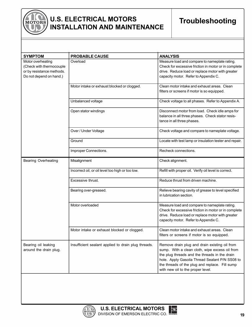
X. FUNDAMENTAL TROUBLESHOOTING - PROBLEM ANALYSIS
This chart can reduce work and time spent on motor analysis. Always check the chart first before startingmotor disassembly, as what appears to be a motor problem may often be located elsewhere. For additionalinformation, consult our website at www.usmotors.com.
SYMPTOMMotor fails to start
Motor fails to comeup to speed
Motor Vibrates
Motor noisy
PROBABLE CAUSEDefective power supplyBlown or defective primary fusesBlown or defective secondary fuses
Open control circuitOverload trips are openDefective holding coil in magnetic switch
Loose or poor connections in control circuits.
Magnetic switch closesPoor switch contactOpen circuit in control panelOpen circuit in leads to motorLeads improperly connectedLow or incorrect voltage
Incorrect connection at motor
Overload - mechanical
Overload - hydraulic
Headshaft misaligned
Worn line shaft bearings or bent line shaft
Hydraulic disturbance in discharge piping
Ambient Vibration
System Natural Frequency (Resonance)
Worn thrust bearing
Electrical noise
ANALYSISCheck voltage across all phases abovedisconnect switch.Check voltage below fuses (all phases)with disconnect closed.Push reset button.
Push start button and allow sufficient time foroperation of time delay, if used, then check voltageacross magnetic holding coil. If correct voltage ismeasured, coil is defective. If no voltage is mea-sured, control circuit is open.Make visual inspection of all connections in controlswitch.Open manual disconnect switch, close magnetic byhand, and examine contractors and springs.Check voltage at Tl, T2, & T3Check voltage at leads in outlet boxCheck lead numbers and connections.Check voltage at Tl, T2, & T3 in control panel and atmotor leads in outlet box.Check for proper lead connections at motorand compare with connection diagram on motor.Check impeller setting. Check for a tight orlocked shaft.Check impeller setting. Check GPM againstpump capacity and head.Remove top drive coupling and check alignment ofmotor to pump.Disconnect motor from pump and run motoronly to determine source of vibration.Check isolation joint in discharge piping near pumphead.Check base vibration level with motor stopped.
Revise rigidity of support structure.
Remove dust cover, rotate rotor by hand, and makevisual examination of balls and races. Bearingnoise is commonly accompanied by a highfrequency vibration and/or increased temp.Most motors are electrically noisy during thestarting period. This noise should diminish asmotor reaches full speed.
U.S. ELECTRICAL MOTORSDIVISION OF EMERSON ELECTRIC CO.
U.S. ELECTRICAL MOTORSINSTALLATION AND MAINTENANCE
ANALYSISMeasure load and compare to nameplate rating.Check for excessive friction in motor or in completedrive. Reduce load or replace motor with greatercapacity motor. Refer to Appendix C.
Clean motor intake and exhaust areas. Cleanfilters or screens if motor is so equipped.
Check voltage to all phases. Refer to Appendix A.
Disconnect motor from load. Check idle amps forbalance in all three phases. Check stator resis-tance in all three phases.
Check voltage and compare to nameplate voltage.
Locate with test lamp or insulation tester and repair.
Recheck connections.
Check alignment.
Refill with proper oil. Verify oil level is correct.
Reduce thrust from driven machine.
Relieve bearing cavity of grease to level specifiedin lubrication section.
Measure load and compare to nameplate rating.Check for excessive friction in motor or in completedrive. Reduce load or replace motor with greatercapacity motor. Refer to Appendix C.
Clean motor intake and exhaust areas. Cleanfilters or screens if motor is so equipped.
Remove drain plug and drain existing oil fromsump. With a clean cloth, wipe excess oil fromthe plug threads and the threads in the drainhole. Apply Gasoila Thread Sealant P/N SS08 tothe threads of the plug and replace. Fill sumpwith new oil to the proper level.
PROBABLE CAUSEOverload
Motor intake or exhaust blocked or clogged.
Unbalanced voltage
Open stator windings
Over / Under Voltage
Ground
Improper Connections.
Misalignment
Incorrect oil, or oil level too high or too low.
Excessive thrust.
Bearing over-greased.
Motor overloaded
Motor intake or exhaust blocked or clogged.
Insufficient sealant applied to drain plug threads.
Troubleshooting
SYMPTOMMotor overheating(Check with thermocoupleor by resistance methods.Do not depend on hand.)
Bearing Overheating
Bearing oil leakingaround the drain plug.
19
U.S. ELECTRICAL MOTORSDIVISION OF EMERSON ELECTRIC CO.
U.S. ELECTRICAL MOTORSINSTALLATION AND MAINTENANCE Spare Parts
XI. SPARE PARTS
A parts list is available for your unit and will be furnished upon request. Parts may be obtained from local U.S.Electrical Motors distributors and authorized service shops, or through U.S. Electrical Motors distribution center.
U.S. ELECTRICAL MOTORS3363 Miac Cove
Memphis, Tennessee 38118(901) 366-4225
Drawings for many standard designs are supplied on the following pages. Most of the parts should be easy toidentify. If however, there is some deviation from your machine, consult the factory for assistance.
20

U.S. ELECTRICAL MOTORSDIVISION OF EMERSON ELECTRIC CO.
U.S. ELECTRICAL MOTORSINSTALLATION AND MAINTENANCE
Spare Parts 250 and 280 Frames
Type AU HIGH THRUST
21
LOCKNUT & LOCKWASHER
BOLTED COUPLING
BALL RETAINING PLATE
PUMP HEADSHAFT(SUPPLIED WITH PUMP)
GUIDE BEARING
CANOPY CAP
RATCHET BALL (OPT)
ROTATING RATCHET (OPT)
STATIONARY RATCHET(OPT)
AIR DEFLECTORS
STATOR
THRUST BEARING
RODENT SCREEN
ROTOR
GREASE FILL
HOLLOW SHAFT
GIB KEY
GREASE DRAIN
LOWER BRACKET
BEARING CAP
UPPER BRACKET

U.S. ELECTRICAL MOTORSDIVISION OF EMERSON ELECTRIC CO.
U.S. ELECTRICAL MOTORSINSTALLATION AND MAINTENANCE
Spare Parts320 Thru 440 Frame
Type RU - High Thrust
22
PUMP HEADSHAFT(SUPPLIED WITH PUMP)
GIB KEY
LOCKNUT & WASHER
STATIONARY RATCHETTANDEM BEARINGS(EXTRA HIGH THRUST)
OIL VIEWING WINDOW
OIL DRAIN PLUG
ROTOR FAN BLADE
HOLLOW SHAFT
BEARING CAP
SNAP RINGSLINGERGUIDE BEARINGGREASE FILL
STATOR
AIR DEFLECTOR
RODENT SCREEN
SINGLE BEARING(STANDARD HIGH THRUST)
BEARING MOUNT
PUMP SHAFT ADJUSTING NUT AND LOCKING SCREWSARE FURNISHED BY CUSTOMER
COUPLINGCANOPY CAP
OIL TUBEOIL FILL PLUG
RODENT SCREEN
ROTATING RATCHET
UPPER BRACKET
LOWER BRACKET
BALL RETAINING RINGRATCHET BALL

U.S. ELECTRICAL MOTORSDIVISION OF EMERSON ELECTRIC CO.
U.S. ELECTRICAL MOTORSINSTALLATION AND MAINTENANCE
Spare Parts440 Frame, Type RV-4
(2 Pole)
23
BEARING SPACER SET
UPTHRUST BEARING
SOLID SHAFT
BEARING CAP
DUST COVER(HEAT EXCHANGER)
FAN CANOPY CAPLOCKNUT & SHAFT ADJUSTING PLATE
FAN COVER
BEARING CAP
DOWN THRUST BEARING
LOCKNUT
RODENT SCREEN
GUIDE BEARING
GREASE FILL
SLINGER
RODENT SCREEN
AIR DEFLECTOR
RODENT SCREEN
STATOR
ROTOR
AIR DEFLECTOR
PRESSUREEQUALIZER TUBE
OIL FILL PLUG
OIL VIEWINGWINDOW
OIL DRAIN PLUG
GREASE DRAIN
"O" RING
BEARING MOUNT
OIL METERING PLUG

U.S. ELECTRICAL MOTORSDIVISION OF EMERSON ELECTRIC CO.
U.S. ELECTRICAL MOTORSINSTALLATION AND MAINTENANCE
Spare Parts280, 320, 360 FRAMES, TYPE LU
320, 360 FRAMES TYPE TU
24
CANOPY CAP
GIB KEYBOLTED COUPLING
LOCKNUT & LOCKWASHER
FANKEY
COUPLING ADAPTOR
BEARING CAP
UPTHRUST &GUIDE BEARING
GREASE FILL
ROTOR
STATOR
BEARING CAP
TANDEM THRUSTBEARINGS(175% EHT)
GREASE DRAIN
OPTIONAL STABILIZER BUSHING
SINGLE BEARING(STANDARD HIGH THRUST)
GREASE FILL
GREASE DRAIN
STATIONARY RATCHET &BEARING CAP
ROTATING RATCHET
RATCHET BALL
PUMP HEADSHAFT & NUT(SUPPLIED WITH PUMP)
BALL RETAINING RING
BEARING CAP
UPPER BRACKET
FAN COVER GUARD
LOWER BRACKET

U.S. ELECTRICAL MOTORSDIVISION OF EMERSON ELECTRIC CO.
U.S. ELECTRICAL MOTORSINSTALLATION AND MAINTENANCE
Spare Parts400 Thru 440 Frame
Types TU, LU, TV-4 and LV-4High Thrust
25
CANOPY CAP
COUPLING
FAN
FAN COVER
THRUST BEARINGS(EXTRA HIGH THRUST)
BEARING CAP
OIL TUBE
BEARING MOUNT
UPPER BRACKET
LOCK NUT &LOCK WASHER
KEY
THRUST BEARING(STD HIGH THRUST)
OIL FILL PLUG
OIL DRAIN PLUG
OIL VIEWINGWINDOW
OIL BAFFLE PLATE
STATOR
ROTOR
LOWER BRACKET
INNER BEARING CAP
OUTER BEARING CAP(440 FRAME ONLY)
SOLID SHAFT
HOLLO SHAFT
GREASE FILL
SLINGER
GUIDE BEARING
BEARING SPACER

U.S. ELECTRICAL MOTORSDIVISION OF EMERSON ELECTRIC CO.
U.S. ELECTRICAL MOTORSINSTALLATION AND MAINTENANCE
Spare Parts449 Frame
Types JV & JV-3
26
FAN COVER
FAN
GREASE FILL
THRUST BEARING
STATOR
CONDUIT BOX
GREASE DRAIN
ROTOR
ROTOR FAN BLADES
BEARING CAP
GUIDE BEARING
BEARING CAP
UPPER BRACKET
LOCKNUT &LOCKWASHER
GREASE FILLGREASE DRAIN
LOWER BRACKET

U.S. ELECTRICAL MOTORSDIVISION OF EMERSON ELECTRIC CO.
U.S. ELECTRICAL MOTORSINSTALLATION AND MAINTENANCE
Spare Parts449 Frame
Type JV-4 (2 Pole)
27
FAN COVER
OIL DRIP PAN
OIL DRAIN
DUST COVER / HEAT EXCHANGER
OIL VIEWINGWINDOW
SHAFT ADJUSTMENTPLATE
LOCKNUT &LOCKWASHER
OIL FILL PLUG
UPPER BRACKET
FAN
BEARING CAP
COOLING COILS
OIL METERINGPLUG
EXTRA HIGH THRUSTTANDEM SPRING-LOADED BEARING ARRANGEMENT
TANDEM THRUSTBEARINGS
BEARING SPACERWITH SPRINGS
OIL TUBE
LOWER GUIDE BEARINGFOR TANDEM UPPER BEARING ARRANGEMENT
LOCATINGBEARING CAP
LOWER BRACKET
NON-LOCATINGBEARING CAP
GREASE FILLGUIDE BEARING
SLINGER
GREASE DRAIN
SOLID SHAFT
ROTOR
STATOR
BEARING LOCKNUTAND LOCK WASHER
BACK-TO-BACKTHRUST BEARINGS

U.S. ELECTRICAL MOTORSDIVISION OF EMERSON ELECTRIC CO.
U.S. ELECTRICAL MOTORSINSTALLATION AND MAINTENANCE
FAN COVER
SQUARE KEY
FAN
BEARING MOUNT
TANDEM THRUST BEARINGS(EXTRA HIGH THRUST)
OIL FILL
STEADY BUSHING(OPTIONAL)
HOLLO SHAFT
SOLID SHAFT
BEARING CAP
STATOR
ROTOR
OIL DRAIN
OIL VIEWING WINDOW
OIL FILL PLUG
LOCKNUT ANDLOCK WASHER
LOWER P-BASE BRACKET
OIL DRAIN
GUIDE BEARING
UPPER BRACKET
HOLLOSHAFT COUPLING
DUST COVER
THRUST BEARING(STD HIGH THRUST)
OIL METERING HOLE
OIL TUBE
SPHERICAL ROLLERTHRUST BEARING(EXTRA HIGH THRUST)
OIL BAFFLE
BEARING SPACERWITH SPRINGS
COOLING COIL(OPTIONAL)
BEARING SPACER
Spare Parts5800 Frame
Types JU, JV-4, EU, EV-4(4 Pole & Slower)
ACCESSORYCONDUIT BOX
MAIN CONDUIT BOX
28

U.S. ELECTRICAL MOTORSDIVISION OF EMERSON ELECTRIC CO.
U.S. ELECTRICAL MOTORSINSTALLATION AND MAINTENANCE
Spare Parts449 Frame
Types JU and JV-4(4 Pole & Slower)
29
FAN COVER
SQUARE KEY
FAN
BEARING MOUNT
TANDEM THRUST BEAR-INGS(EXTRA HIGH THRUST)
GREASE FILL
SLINGERHOLLO SHAFTSOLID SHAFT
BEARING CAP
STATOR
ROTOR
OIL DRAIN
OIL VIEWING WINDOW
OIL FILL PLUG
LOCKNUT ANDLOCK WASHER
LOWER P-BASE BRACKET
GREASE DRAIN
GUIDE BEARING
UPPER BRACKET
HOLLOSHAFT COUPLING
DUST COVER
THRUST BEARING(STD HIGH THRUST)
OIL METERING HOLE
OIL TUBE
SPHERICAL ROLLERTHRUST BEARING(EXTRA HIGH THRUST)
OIL BAFFLE
BEARING SPACERWITH SPRINGS
COOLING COIL(OPTIONAL)
BEARING SPACER

U.S. ELECTRICAL MOTORSDIVISION OF EMERSON ELECTRIC CO.
U.S. ELECTRICAL MOTORSINSTALLATION AND MAINTENANCE
FAN COVER
OIL DRIP PAN
OIL DRAIN
DUST COVER / HEAT EXCHANGER
OIL VIEWINGWINDOW
SHAFT ADJUSTMENTPLATE
LOCKNUT &LOCKWASHER
OIL FILL PLUG
UPPER BRACKET
FAN
BEARING CAP
COOLING COILS
OIL METERINGPLUG
EXTRA HIGH THRUSTTANDEM SPRING-LOADED BEARING ARRANGEMENT
TANDEM THRUSTBEARINGS
BEARING SPACERWITH SPRINGS
OIL TUBE
LOWER GUIDE BEARINGFOR TANDEM UPPER BEARING ARRANGEMENT
LOCATINGBEARING CAP
LOWER BRACKET
NON-LOCATINGBEARING CAP
OIL FILL
GUIDE BEARINGOIL VIEWINGWINDOW
OIL DRAIN
SOLID SHAFT
ROTOR
STATOR
BEARING LOCKNUTAND LOCK WASHER
Spare Parts5800 Frame
Type JV-4 & EV-4 (2 Pole)
MAIN CONDUIT BOX
ACCESSORYCONDUIT BOX
BALANCING DISK
BACK-TO-BACKTHRUST BEARINGS
30

U.S. ELECTRICAL MOTORSDIVISION OF EMERSON ELECTRIC CO.
U.S. ELECTRICAL MOTORSINSTALLATION AND MAINTENANCE
Spare Parts5000-6800 Frame, Types HU&HV4
8000 Frame, Types RU&RV4(4-Pole and Slower)
31
PUMP SHAFT, ADJUSTING NUT, AND LOCKING SCREWSARE FURNISHED BY CUSTOMER
CANOPY CAP
GIBKEY
SPHERICAL ROLLERTHRUST BEARING
BEARING PRELOADSPRINGS & SPACER
DRIVECOUPLING
DUST COVER
LOCKNUT &LOCKWASHER
BEARING MOUNTING
TANDEM THRUST BEARINGS
AIR INTAKE
LIFTING LUG
AIR EXHAUST
AIR INTAKE
SOLID SHAFT
OIL TUBE(STAND PIPE)
OIL VIEWING WINDOW
OIL DRAIN
OIL METERING HOLE
ROTOR FAN BLADE
ROTOR
STATOR
OIL VIEWING WINDOW(SOME UNITS HAVE GREASE
LUBRICATED LOWER BEARiNG)
BEARING CAP
LOWER P-BASE BRACKET HOLLOSHAFT
GUIDE BEARING
OIL FILL
OIL DRAIN
SINGLE THRUST BEARING
STEADY BUSHING (OPTIONAL)
AIR DEFLECTOR
AIR DEFLECTOR
OIL BAFFLE
WATER COOLINGCOIL (OPTIONAL)
SHROUDING IS ONLY PROVIDED ONWEATHER PROTECTED TYPE II MOTORS
EXTRA HIGH THRUST DESIGN WITH SPRING-LOADEDSPHERICAL ROLLER THRUST BEARING
SQUARE KEY

U.S. ELECTRICAL MOTORSDIVISION OF EMERSON ELECTRIC CO.
U.S. ELECTRICAL MOTORSINSTALLATION AND MAINTENANCE
CANOPY CAPGIBKEY
SPHERICAL ROLLERTHRUST BEARING
BEARING SPACERWITH SPRINGS
DRIVECOUPLING
STATIONARY RATCHET(OPTIONAL)
LOCKNUT &LOCKWASHER
BEARING MOUNTING
SINGLE THRUST BEARING(FOR STD HIGH THRUST)
AIR INTAKE
LIFTING LUG (WITHSHIPPING TIE-DOWN)
AIR EXHAUST
AIR INTAKE
SOLID SHAFT
OIL TUBE(STAND PIPE)
OIL VIEWING WINDOW
OIL DRAIN
OIL METERING PLATE
ROTOR
STATOR
OIL VIEWING WINDOW
BEARING CAP
LOWER P-BASE BRACKET
HOLLOSHAFT
GUIDE BEARING
OIL FILL
OIL DRAIN
OIL FILL
STEADY BUSHING (OPTIONAL)
AIR DEFLECTORS
OIL BAFFLE
RATCHET PRESSUREPLATE (OPTIONAL)
SHROUDING ONLY PROVIDEDON WEATHER-PROT. TYPE II
EXTRA HIGH THRUST DESIGN WITH SPRING-LOADEDSPHERICAL ROLLER THRUST BEARING
SQUARE KEY
ROTATING RATCHET(PIN TYPE)
END OF C-SHAPEDCONNECTION SPRING(OPTIONAL)
DUST COVER /RATCHET ADAPTOR
Spare Parts9600 Frame
Types RU and RV-4
32
U.S. ELECTRICAL MOTORSDIVISION OF EMERSON ELECTRIC CO.
U.S. ELECTRICAL MOTORSINSTALLATION AND MAINTENANCE
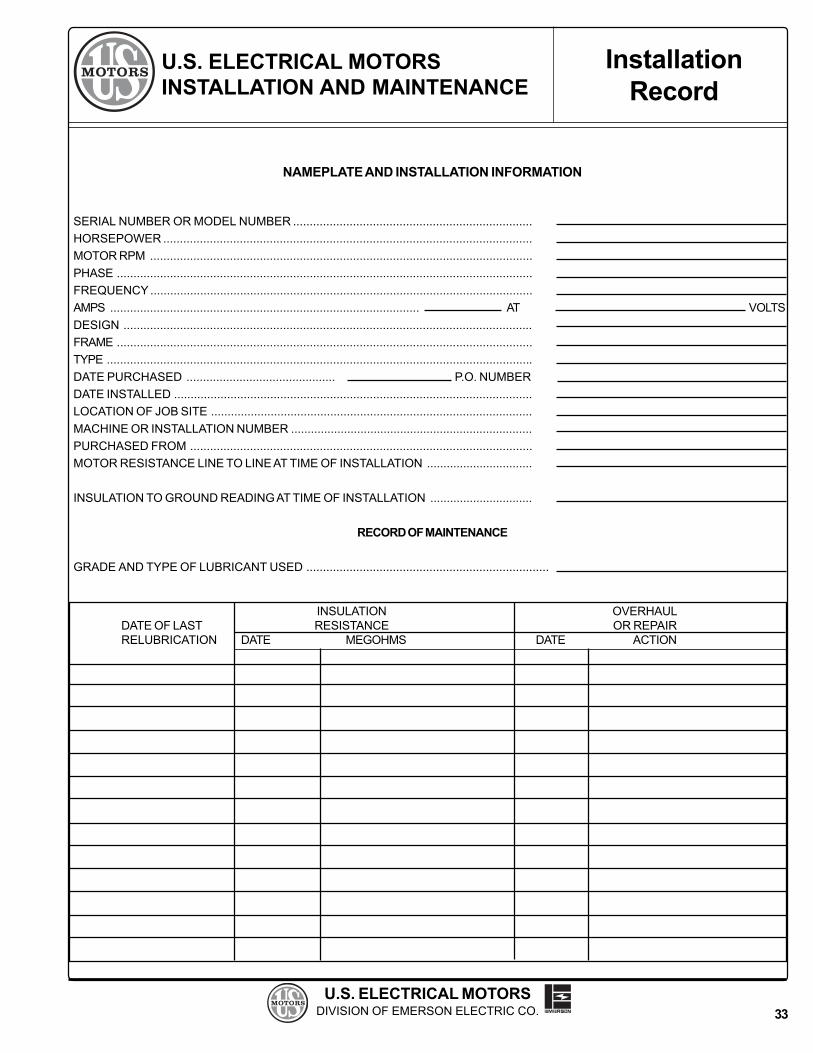
NAMEPLATE AND INSTALLATION INFORMATION
SERIAL NUMBER OR MODEL NUMBER ........................................................................HORSEPOWER ...............................................................................................................MOTOR RPM ...................................................................................................................PHASE .............................................................................................................................FREQUENCY...................................................................................................................AMPS .............................................................................................DESIGN ...........................................................................................................................FRAME .............................................................................................................................TYPE ................................................................................................................................DATE PURCHASED ............................................. P.O. NUMBERDATE INSTALLED ............................................................................................................LOCATION OF JOB SITE .................................................................................................MACHINE OR INSTALLATION NUMBER .........................................................................PURCHASED FROM .......................................................................................................MOTOR RESISTANCE LINE TO LINE AT TIME OF INSTALLATION ................................
INSULATION TO GROUND READING AT TIME OF INSTALLATION ...............................
RECORD OF MAINTENANCE
GRADE AND TYPE OF LUBRICANT USED .........................................................................
INSULATION OVERHAULDATE OF LAST RESISTANCE OR REPAIRRELUBRICATION DATE MEGOHMS DATE ACTION
InstallationRecord
AT VOLTS
33

U.S. ELECTRICAL MOTORSDIVISION OF EMERSON ELECTRIC CO.
U.S. ELECTRICAL MOTORSINSTALLATION AND MAINTENANCE
Table 6Threaded Fastener Torque Requirements
All threaded fasteners used for rigid joints (cast iron and low carbon steel) in products of U.S. Electrical Motors, areto be tightened to the torque values listed in the following tabulation. Values are based upon dry assembly.
Diameter of Number of Threads Grade5 Grade 2Fastener Per Inch Fasteners Fasteners
#6 32 16 lb.-in. 10 lb.-in40 18 12
#8 32 30 1936 31 20
#10 24 43 2732 49 31
#12 24 66 3728 72 40
1/4" 20 96 6628 120 76
5/16" 18 16 lb.-ft. 11 lb.-ft.24 18 12
3/8" 16 29 2024 34 23
7/16" 14 46 3020 52 35
1/2" 13 70 5020 71 55
9/16" 12 10218 117
5/8" 11 14018 165
3/4" 10 24916 284
7/8" 9 40114 446
1" 8 60114 666
1-1/8" 7 74212 860
1-1/4" 7 104612 1196
1-3/8" 6 137112 1611
1-1/2 6 182012 2110
The above torque limits are not to be used when a drawing or specification lists a specific torque.
34
InstallationRecord

U.S. ELECTRICAL MOTORSDIVISION OF EMERSON ELECTRIC CO.
U.S. ELECTRICAL MOTORSINSTALLATION AND MAINTENANCE
Effects of Unbalanced Line Voltage.
A potential cause of premature motor failure is unbalanced line (supply) voltage. Three phase motors produce usefulwork when they efficiently convert electrical energy into mechanical energy. This is accomplished when each phase ofthe supply voltage is of equal strength and works in harmony to produce a rotating magnetic field within the motor.
When the value of supply voltage leg to leg is not equal (e.g. 460-460-460), the risk of unbalanced line voltage is present.If this voltage unbalance exceeds about 1%, excessive temperature rise will result. Unless the motor HP capacity isderated to compensate, the motor will run hot resulting in degradation of the insulation system and bearing lubricant.
From NEMA MG-1, 14.35: Derating factors due to unbalanced line voltage
Example: Field ratings of Phase A - 480 v, Phase B = 460 v, Phase C = 450 v
As a rule of thumb, the percentage increase in temperature rise will be about two times the square of the percentagevoltage unbalance. In this case the average voltage (480 + 460 + 450) is equal to 463 volts. The maximum deviationbetween legs is 17 volts (480 - 463 volts).
The Percentage voltage unbalance is determined as follows: 17 / 463 x 100 = 3.7%. The temperature rise will thenincrease (3.7)2 x 2 = 27%. This condition will reduce the typical life of your motor to less than 25% of its design life.Should this condition be present, call your electric utility and resolve your unbalanced supply condition.
Other areas of motor performance will also be effected - e.g., loss of torque capacity, change in full load RPM, greatlyunbalanced current draw at normal operating speed. Refer to NEMA MG-1 section 14.35 for details.
Appendix A
35

U.S. ELECTRICAL MOTORSDIVISION OF EMERSON ELECTRIC CO.
U.S. ELECTRICAL MOTORSINSTALLATION AND MAINTENANCE
Motors Applied to Variable Frequency Drives (VFD's).
Electric motors can be detrimentally affected when applied with variable frequency drives (VFD's). The non-sinusoidalwaveforms of VFD's have harmonic content which causes additional motor heating; and high voltage peaks and shortrise times, which result in increased insulation stress, especially when long power cable lengths are used. Otheraffects of VFD's on motor performance include reduced efficiency, increased load current, vibration and noise. Stan-dard motors utilized with VFD's must be limited to those application considerations defined in NEMA MG-1 Part 30.
NEMA MG-1 Part 31 defines performance and application considerations for Definite-Purpose Inverter Fed motors. Toinsure satisfactory performance and reliability, U.S. Motors offers and recommends nameplated inverter duty motorproducts which meet the requirements of NEMA MG-1 Part 31. The use of non-inverter duty motors may result inunsatisfactory performance or premature failure, which may not be warrantable under the Terms and Conditions ofSale. Contact your U.S. Motors Field Sales Engineer for technical assistance in motor selection, application andwarranty details.
Appendix B
36

U.S. ELECTRICAL MOTORSDIVISION OF EMERSON ELECTRIC CO.
U.S. ELECTRICAL MOTORSINSTALLATION AND MAINTENANCE
ELECTRIC MOTOR LOAD TEST USING THE WATT HOUR METER
In the analysis of electric motors it is sometimes desirable to conduct an accurate load check on a particular installa-tion to determine whether the motor is operating within the rating and horsepower for which it was designed. Sincemost pump installations have their own watt hour power meters, accurate readings will permit a load check via thefollowing formula:
K = Disc constant (watts per revolution of disc per hour). This is typically found on the meter face.
R = Revolutions of disc in watt meter within the time of the test.
T = Time of test, in seconds.
Transformer ratio = Stated on meter face. Must be included where current transformers are used with wattmeters.
To obtain input kilowatts:
To obtain input horsepower:
The watt hour meter measures power consumed over a period of time. It is necessary to establish the rate at whichpower is being consumed by the work being done. We establish this rate by counting the revolutions of the disc in agiven time. Here is a typical example of a load check:
GIVEN� Pump motor to be load checked is rated 100 HP, 1800 RPM, 3-phase, 60 Hz, 1.15 service factor, 91.0
Percent Efficiency.
� Disc constant (K) found on face of meter = 40.
� Transformer ratio found on face of meter = 3.
DATA FOUND FROM TESTSWith stop watch, disc was observed to revolve 10 times in exactly 49 seconds. Therefore, R = 10; T = 49.
THUS Input HP= 40 x 10 x 4.83 x 3 = 118.2949
Output HP = Input HP x Motor EfficiencyOutput HP = 118.29 x 91% = 107.54
CONCLUSIONThe output HP (107.54) is greater than output HP shown on nameplate (100 HP), but is well within the 1.15service factor which applies to this motor.
Input KW = K x R x 3.6 T
Input HP = K x R x 4.83 x Transformer RatioT
Appendix C
37

REGIONAL OFFICES PHONE FAXDOMESTIC U.S. SALES (888) 637-7333 (314) 553-1101INTERNATIONAL SALES (314) 553-3185 (314) 553-2135MONTREAL, QUEBEC/CANADA (800) 361-5509 (514) 332-5912TORONTO, ONTARIO/CANADA (905) 475-4670 (905) 475-4672
©2000 U.S. Electrical Motors - Prices, specifications and ratings subject to change without notice.Printed in the U.S.A
U.S. Electrical Motors Division, Emerson Electric Co.8100 West Florissant Avenue, St. Louis, MO 63136
WWW Home Page: http://www.usmotors.com
IN509-1D 11/00
MONTERREY, MEXICO (52) 8-389-1312 (52) 8-389-1310CARACAS, VENEZUELA (58) 02-2377522 (58) 02-2329727BOGOTA, COLOMBIA (57)1- 439-5420 (57)1- 439-5417