vertical drop testing and analysis of the wasp helicopter ... · vertical drop testing and analysis...
TRANSCRIPT
Vertical Drop Testing and Analysis of the WASP Helicopter Skid Gear
Yvonne T. Fuchs and Karen E. Jackson
[email protected] and [email protected]
NASA Langley Research Center
Hampton, VA 23681-2199
Abstract
Human occupant modeling and injury risk assessment have been identified as areas of research for improved
prediction of rotorcraft crashworthiness within the NASA Aeronautics Program’s Subsonic Rotary Wing Project.
As part of this effort, an experimental program was conducted to assess the impact performance of a skid gear for
use on the WASP kit-built helicopter, which is marketed by HeloWerks, Inc. of Hampton, Virginia. Test data from
a drop test at an impact velocity of 8.4 feet-per-second were used to assess a finite element model of the skid gear
test article. This assessment included human occupant analytic models developed for execution in LS-DYNA. The
test article consisted of an aluminum skid gear mounted beneath a steel plate. A seating platform was attached to the
upper surface of the steel plate, and two 95th percentile Hybrid III male Aerospace Anthropomorphic Test Devices
(ATDs) were seated on the platform and secured using a four-point restraint system. The goal of the test-analysis
correlation is to further the understanding of LS-DYNA ATD occupant models and responses in the vertical (or
spinal) direction. By correlating human occupant experimental test data for a purely vertical impact with the LS-
DYNA occupant responses, improved confidence in the use of these tools and better understanding of the limitations
of the automotive-based occupant models for aerospace application can begin to be developed.
Introduction
Since its inception in 2006, the Rotorcraft
Crashworthiness task under the NASA Aeronautics
Program’s Subsonic Rotary Wing (SRW) Project has
focused attention on two main areas of research:
development of an externally deployable energy
absorbing concept and improved prediction of rotorcraft
crashworthiness [1]. The energy absorber being
developed is a composite honeycomb structure that can
be externally deployed to provide energy attenuation,
much like an external airbag system [2]. The second
main research area relates to crash modeling and
simulation. Several research topics have been identified
to achieve improved prediction of rotorcraft
crashworthiness, including: fundamental materials
characterization, human occupant modeling and injury
prediction, multi-terrain impact simulation,
development of fully integrated simulation models, and
validation studies that focus on probabilistic analysis
and uncertainty quantification. In order to pursue the
research to improve analytical prediction of rotorcraft
crashworthiness, NASA requires relevant experimental
data.
In 2007, HeloWerks, Inc. of Hampton, VA approached
NASA to conduct a test evaluation program on a
Presented at the American Helicopter Society 64th
Annual Forum, Montreal, Canada, April 29 – May 1,
2008. This paper is a work of the US Government and
is, therefore, in the public domain.
skid gear design for their HX-2 WASP, a 1,000-lb.
gross weight kit-built two-seat helicopter fabricated
using monocoque composite sandwich construction.
The helicopter is 19-ft. long, 9-ft. high, and 7-ft. wide at
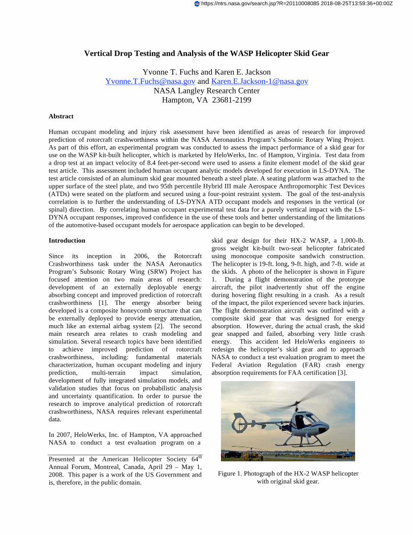
the skids. A photo of the helicopter is shown in Figure
1. During a flight demonstration of the prototype
aircraft, the pilot inadvertently shut off the engine
during hovering flight resulting in a crash. As a result
of the impact, the pilot experienced severe back injuries.
The flight demonstration aircraft was outfitted with a
composite skid gear that was designed for energy
absorption. However, during the actual crash, the skid
gear snapped and failed, absorbing very little crash
energy. This accident led HeloWerks engineers to
redesign the helicopter’s skid gear and to approach
NASA to conduct a test evaluation program to meet the
Federal Aviation Regulation (FAR) crash energy
absorption requirements for FAA certification [3].
Figure 1. Photograph of the HX-2 WASP helicopter
with original skid gear.
https://ntrs.nasa.gov/search.jsp?R=20110008085 2018-08-25T13:59:36+00:00Z

Simulation of the HeloWerks redesigned skid gear
provided an opportunity for NASA to evaluate current
occupant modeling capabilities within LS-DYNA [4]
using vertical impact test data from a fairly simple test
article. Helicopter crashworthiness is unique in the crash
industry due to the large vertical component of
acceleration that is transmitted to the occupants. In
contrast, frontal and side accelerations are much more
predominant in the automotive crash environment. The
automotive industry has made a tremendous investment
into developing finite element models of
Anthropomorphic Test Devices (ATDs) commonly used
in automotive crash testing.
Note that although the LS-DYNA models are referred to
as human occupant models, they are truly modeled after
the standards set forth for ATDs, which themselves are
physical models meant to mimic human responses.
There are also differences between the physical ATDs
available for automotive use and aviation use.
Automotive ATDs have a curved spine; Aerospace
ATDs have a vertical spine to allow for load cells to
measure lumbar loads. The development of Aerospace
ATDs was driven by ejection seat testing, thus
necessitating the ability to modify a standard
automotive ATD to measure for vertical accelerations
and loading [5]. However, very little research has been
done to determine what, if any, refinements are needed
to commercially available analysis models of
automotive ATDs for aerospace applications.
To pursue this mutually beneficial program, a
cooperative agreement was developed between
HeloWerks, Inc. and NASA Langley Research Center
[6]. As part of this program, HeloWerks designed and
fabricated the test articles. NASA instrumented the test
articles, performed the vertical drop tests, and shared all
test information with HeloWerks.
Experimental Program
The complete details of the test program evaluating
HeloWerks skid gear designs are documented in
Reference 7. Out of all of these tests, the 8.4-fps impact
test of the final skid gear design was selected to evaluate
the human occupant response models in LS-DYNA. A
short overview of the experimental program focusing on
results from this particular test is included in this paper
for reference in the test-analysis correlation discussion
to follow.
As mentioned previously, the original skid gear used on
the WASP helicopter was a composite design that did
not function as intended in an actual crash. The gear
was redesigned based on the work reported in Reference
8. The redesigned gear was fabricated using aluminum
circular cross-section tubes; the tubes were reinforced at
the crossbeam attachments using 4130 steel sleeves and
at the intersection with the skid beams using saddles to
prevent premature collapse and local buckling of the
gear. The fully instrumented test article, shown in
Figure 2, weighed 1,064 lb, including 320 lbs of ballast
and 450 lbs for the two 95th percentile Hybrid III male
Aerospace ATDs. The test article consisted of the
redesigned skid gear mounted beneath a steel plate, a
seating platform attached to the upper surface of the
steel plate, and two 95th percentile Hybrid III male
Aerospace ATDs seated on the platform and secured
using a four-point restraint system. Ballast weights were
mounted to the test article to ensure the correct position
of the Center-of-Gravity (CG). These parts are shown in
Figure 3.
Figure 2. Front view of test article with ATD naming
convention.
An opening was cut into the seat platform to allow
space for seat foam filler, as shown in Figure 3(b). The
foam filler space under ATD-1 was filled with several
layers of Styrofoam, as shown in Figure 4(a) and 4(b).
Under ATD-2, three blocks of polyisocyanurate foam
were used, as shown in Figure 4(c) and 4(d), with two
blocks facing forward and one intersecting block
positioned laterally.
ATD-1 Styrofoam
ATD-2 Polyisocyanurate

(a) Front view.
(b) Side view.
Figure 3. Schematic of the test article.
The test article and two 95th
percentile Aerospace ATDs
were instrumented with a total of 26 accelerometers and
2 lumbar load cells. Test data were collected at 50,000
samples per second using a digital data acquisition
system. The vertical drop test was performed by
attaching lifting cables to the test article, raising the test
article through its CG, and then releasing the test article
to impact a smooth concrete surface.
Test Results: 8.4-fps Vertical Drop Test
The test article was lifted to a height of 13 inches and
released to impact a smooth concrete surface at 8.4-fps.
Post-test measurements of permanent deformation show
that the measured spread of the skid gear was 4.4
inches. No permanent deformation of either the
Styrofoam stack or the polyisocyanurate foam blocks
was visible post-test.
Comparisons of the two Aerospace ATD occupants’
filtered vertical acceleration responses of the head,
chest, and pelvis are shown in Figure 5. Data were
post-processed using an SAEJ211 equivalent low-pass
filter with a cut-off frequency of 33.5 Hz [9]. The peak
magnitudes of the acceleration responses range from 6
to 9g. The acceleration responses of the head have the
lowest magnitude (6g) and the pelvic acceleration
responses have the highest magnitude (9g). Some
minor differences are seen between the ATD-1 and
ATD-2 acceleration responses for the head and chest;
however, both curves have similar magnitudes. ATD-2
exhibits a higher peak acceleration of 9-g in the pelvis,
than seen for ATD-1 (8-g).
(a) Styrofoam layers (ATD-1) side view.
(b) Styrofoam layers (ATD-1) top view.
(c) Polyisocyanurate blocks (ATD-2) side view.
(d) Polyisocyanurate blocks (ATD-2) top view.
Figure 4. Styrofoam and polyisocyanurate foam fillers.

(a) Head.
(a) Chest.
(c) Pelvis.
Figure 5. Occupant acceleration responses during the
vertical drop test.
Injury Assessment
The dynamic acceleration responses obtained from the
instrumented Aerospace ATDs were used to perform an
injury risk assessment. Several methods are typically
used to evaluate human injury potential, including the
Dynamic Response Index (DRI) [10-12], the Brinkley
Index [13, 14], Lumbar Load limits [12], Head Injury
Criteria [15, 16], and Eiband whole body acceleration
tolerance limits [17, 18]. In this study, occupant injury
was evaluated based on the DRI due to the fact that the
ATDs only experienced significant load in the spinal
direction.
The Dynamic Response Index (DRI) [10-12] is derived
from a simple one-dimensional lumped-mass spring
damper system, as depicted in Figure 6. This model
was developed by the Air Force's Wright Laboratory to
estimate the probability of compression fractures in the
lower spine due to acceleration in a pelvis-to-head
direction, as might be experienced by aircrew during
seat ejections. Operational data from actual ejection
seat incidents indicate that the spinal injury rate for
maximum DRI values between 20 and 23 range from 16
to 50 percent [11, 12]. A plot showing spinal injury rate
versus maximum DRI is shown in Figure 7. This plot
contains operational data, as well as data calculated
from cadaver tests.
Figure 6. Schematic of the DRI injury model.
Figure 7. Plot of spinal injury rate versus maximum
DRI.

The chest and pelvis acceleration responses are plotted
versus the computed continuous DRI responses for
ATD-1 and ATD-2 in Figures 8 and 9, respectively.
The maximum DRI recorded for either of these two
dummies is 7.5. This value is well below the lowest
level indicative of injury, as indicated in Figure 7.
Operational data from actual ejection seat incidents
indicate that the spinal injury rate for a maximum DRI
value of 7.5 is less than 0.2% percent (see Figure 7).
Based on cadaver data, the spinal injury rate for a
maximum DRI of 7.5 is also less than 0.2%.
(a) Chest responses.
(b) Pelvis responses.
Figure 8. ATD-1 acceleration and continuous DRI
responses.
(a) Chest responses.
(b) Pelvis responses.
Figure 9. ATD-2 acceleration and continuous DRI
responses.
Analytical Modeling
A finite element model of the final skid gear test article
including ATD occupants was developed using the
commercial non-linear, explicit transient dynamic code,
LS-DYNA [4]. There are four ATD occupant models
available for use within LS-DYNA. Two of the models
use built-in keyword formats:
*COMPONENT_GEBOD, shown in Figure 10, and
*COMPONENT_HYBRIDIII, shown in Figure 11. The
GEBOD model is a rigid body model only, and the
HYBRIDIII model is rigid with 3 deformable parts that
may be activated. A user may choose to enable the
three deformable parts, choosing from the head skin,

chest, and/or pelvis, which were developed for
interaction with seatbelts and head strike events.
Figure 10. LS-DYNA *COMPONENT_GEBOD model.
Figure 11. LS-DYNA *COMPONENT_HYBRIDIII
model.
There also exists Hybrid III finite element or “stand-
alone” models. There are two versions of this model. A
rigid version, shown in Figure 12, is similar to the built-
in *COMPONENT_HYBRIDIII model in that it has the
same set of three deformable parts that may be
activated. The deformable stand-alone version, shown
in Figure 13, has many more deformable features.
The trade-offs between use of the various models
include CPU and pre-processing time. Due to the fact
that the built-in models are not compiled until a
simulation execution, positioning the occupants
correctly in a model can be a tedious, trial-and-error
effort. The stand-alone models are easier to position,
but are more CPU costly. For the purposes of this
analytic simulation of the skid gear, the built-in
*COMPONENT_HYBRIDIII model was selected for
integration and evaluation.
Figure 12. LS-DYNA stand-alone rigid model.
Figure 13. LS-DYNA stand-alone deformable model.
The complete LS-DYNA finite element model of the
modified skid gear is shown in Figure 14. The
structural model consists of: 52 parts; 12,564 nodes; and
15,511 elements including 11,908 Belytschko-Tsay
quadrilateral shell elements, 2,275 hexagonal solid
elements, 925 beam elements, 371 seatbelt elements,
and 32 lumped mass elements. Material properties were
defined for the various parts including
*MAT_PLASTIC_KINEMATIC for 4130-steel, 6061-
T6 and 2024-T6 aluminum shell elements used to
represent the skid gear test platform and
*MAT_ELASTIC for the plywood and beam elements.
The seat foam fillers were represented using solid
elements that were assigned a material model in LS-
DYNA called *MAT_CRUSHABLE_FOAM. Material
characterization testing was performed to evaluate the
behavior of the two seat foams, Styrofoam and
polyisocyanurate. The test data were used as input for
the material model. The seat foam material
characterization test results are presented in Figure 15.

Figure 14. LS-DYNA model of the skid gear with
occupants.
(a) Polyisocyanurate (ATD-2).
(b) Styrofoam (ATD-1).
Figure 15. Seat foam material characterization results.
The skid gear was modeled using circular cross-section
beam elements of varying thickness. Concentrated
masses were used in the model to represent the ballast
weights. Two Hybrid III 95th
percentile male occupants
were inserted into the structural model using the
*COMPONENT_HYBRIDIII command. These models
represent the human body using rigid links, surrounded
by ellipsoids, with kinematic joints that mimic the
motion of the human body. Once added, the two
occupants were positioned using LS-PrePost [19], a pre-
and post-processing software for LS-DYNA. Beam
seatbelt elements were modeled after the seatbelts used
in the test article to constrain the motion of the occupant
models.
Contact surfaces were defined to represent contact
between the skid gear and the impact surface, between
the occupants and the seatbelts, and between the
occupants and the seating platform. The impact surface
was modeled as a non-rigid surface and given properties
of 4130-steel. The contact friction between the skid
gear and impact surface was defined as 0.1. The model
was executed in LS-DYNA version 971 on a Linux
workstation computer with a single processor. A
simulation time of 0.2 seconds required 8 hours and 50
minutes of CPU time.
Original Model
Comparisons of the filtered vertical acceleration
responses of the pelvis and chest of the two ATD
occupants with LS-DYNA analytical predictions are
shown in Figures 16 and 17, respectively. Both the
experimental and analytical results were filtered with a
SAEJ211 equivalent low-pass filter with a cut-off
frequency of 60 Hz [9]. As a reminder, ATD-1 is seated
on Styrofoam and ATD-2 is seated on polyisocyanurate
foam blocks.
When performing test-analysis correlation with dynamic
acceleration data, three assessments are typically made:
comparisons of peak acceleration, pulse duration, and
pulse shape. In dynamic model test-analysis correlation,
qualitative correlation with up to 15% difference is
considered good correlation. For the original model, the
peak accelerations correlate within an average of 7.4%
for both ATD-1 and ATD-2 pelvis and chest
comparisons. The time duration of the pulse matches
well, but is slightly too short in the analysis data for
both pelvis responses. The general behavior of the
curve matches better for ATD-1 than for ATD-2. There
is a strong secondary pulse shown in the analysis data
for both ATD-1 and ATD-2 with an average over
prediction of 92.5%. Also of note in both ATD-1 and
ATD-2 chest correlation is that the analysis shows a
slight onset rate delay as compared to the test response.

(a) Pelvis response.
(b) Chest response.
Figure 16. ATD-1 (Styrofoam) test data versus updated
LS-DYNA results.
(a) Pelvis response.
(b) Chest response.
Figure 17. ATD-2 (Polyisocyanurate) test data versus
updated LS-DYNA results.
Examining the model further, the energy results, shown
in Figure 18, indicate that there is a sharp increase in the
internal energy at the same time that the strong
secondary pulse is seen in the ATD-2 chest response.
Looking closely, there is also an associated increase in
the hourglass energy at that time that can be traced
down to the hourglass energy associated with the
polyisocyanurate material on which ATD-2 is seated, as
seen in Figure 19. Also seen in Figure 19 is a secondary
hourglass energy spike in the polyisocyanurate foam.
Hourglass energy counteracts the forces to prevent non-
physical element deformations, and a
*HOURGLASS_CONTROL type 6 was defined for the

polyisocyanurate foam. In general, hourglass energy of
10% or less of the total energy is desirable in a model,
and sharp increases in hourglass energy can signify
additional non-physical energy additions and unwanted
deformation shapes of elements.
Figure 18. Original LS-DYNA model energy results.
Figure 19. Original LS-DYNA model polyisocyanurate
foam hourglass energy.
Hourglass energy for foam materials is often related to
the material representation and mesh size. In standard
compression testing, it is typical not to capture the
strong increase in bulk modulus of the foam once the
cells have tightly compacted. This is due to several
factors, one of which is the need to obtain material
characterization data at a strain rate representative to
that which is expected in the test/analysis. Testing the
same material in quasi-static method would not provide
the correlation with the dynamic data or capture the
dynamic hardening effects. As seen in the material test
data that is presented in Figure 15(a), the data ends at
just over 70% strain. Using this material curve alone
will produce non-physical results in LS-DYNA. To
allow the compaction of the elements to propagate from
the top element of the foam down through the foam
without producing negative volume elements in the
finite element model, it is necessary to include the “tail”
in the material represent the large bulk modulus
stiffening of the foam. The original load curve used in
LS-DYNA is shown in Figure 20. When the original
results showed that the hourglass energy from the foam
was observed to impart large, non-physical
accelerations into ATD-2, the tail of the curve was
modified to have a smoother response, as also shown in
Figure 20.
Figure 20. LS-DYNA polyisocyanurate material model
load curves.
Modified Model
Utilizing the modified polyisocyanurate material load
curve as shown in Figure 20, the simulation was
repeated. No other changes to the model were made.
The results of the simple change of the material load
curve on ATD-1 and ATD-2 responses can be seen in
Figures 21 and 22, respectively. The energy results for
the modified model show a much improved internal
energy curve, as shown in Figure 23. Also, the
hourglass energy for the polyisocyanurate foam was
significantly reduced, as shown in Figure 24.
All qualitative correlations are improved for both ATD-
1 and ATD-2, except that the peak acceleration for
ATD-2 is now under predicted by the analysis. The
initial peak magnitudes correlate within an average of
15%, and the secondary peak acceleration magnitudes
correlate within an average of 38.4%. The large
secondary response previously seen in the ATD-2 chest

has been reduced, and in general the ATD-2 analysis
curves now more closely match the shape of the test
acceleration curves. In addition, ATD-1 also saw
benefits in the reduction of energy by modifying the
polyisocyanurate foam response, thus the reduction in
difference in secondary peak magnitude correlation.
(a) Pelvis response.
(b) Chest response.
Figure 21. ATD-1 test data versus updated LS-DYNA
results for the 8.4-fps test.
(a) Pelvis response.
(b) Chest response.
Figure 22. ATD-2 test data versus updated LS-DYNA
results for the 8.4-fps test.
Figure 23.Modified LS-DYNA model internal energy
results.

Figure 24. Modified LS-DYNA model polyisocyanurate
foam hourglass energy.
Comparisons were made between the accelerometer
data from the skid gear itself with nodal accelerations
from matching locations in the analysis model, thus
improving confidence in the overall model.
Representative test-analysis correlations between skid
gear platform accelerometers are presented in Figure 25.
These results are presented for the modified finite
element model; however, changes in the
polyisocyanurate material response had little influence
on the structural responses shown in Figure 25.
The initial peak acceleration is over predicted by an
average of 39%, suggesting that the use of beam
elements, and subsequently elastic material properties,
for the skid gear is leading to too much energy being
transferred into the test platform upon which the LS-
DYNA occupants are seated.
Discussion of Results
The occupant data collected from the two 95th
percentile
Hybrid III male Aerospace ATDs proved useful in
performing an analysis and injury assessment. The DRI
human injury prediction models were applied using the
test data from the 8.4-fps drop test performed in
December 2006. The results of the injury assessment
indicate a maximum DRI value of 7.5, which is
associated with a spinal injury risk of less than 0.2 %,
based on operational data during ejection seat incidents.
The DRI assessment is based solely on the vertical
acceleration responses of the Aerospace ATDs.
(a) Bottom center.
(b) Left rear.
(c) Right rear.
Figure 25. Skid gear platform accelerometer test-
analysis correlation.

Foam filler was used in the seat platform to provide
additional protection to the ATDs. However, no
discernable crushing of the Styrofoam or the
polyisocyanurate foam was measured during any of the
vertical drop tests. The crush response of each material
is shown in Figure 15. Polyisocyanurate foam exhibits
an average crush stress of approximately 57 psi. One
recommendation for improving the crashworthiness
performance of the system would be to incorporate a
lower crush stress foam material. Crushing of the foam
would provide a secondary means of energy absorption.
The LS-DYNA models representing the 95th
percentile
male Hybrid III occupants performed well during the
simulations and generally good agreement with the
experiment was obtained. LS-DYNA occupant peak
acceleration magnitudes correlated within an average of
15%. However, some differences were seen in the
acceleration onset rates. It should be noted that the LS-
DYNA occupant models were developed and validated
for use in automotive crash simulations in which
impulsive loading is primarily in the frontal plane.
Rarely would an occupant experience vertical impulsive
loading in an automotive crash. Therefore, the
difference in acceleration onset rate between test and
analysis correlation is attributed to the development
history of the analysis occupant models.
While the ability to correctly model the seat foam
material proved to be critical in predicting the response
of the ATDs, it is also important to capture the correct
response of the skid gear test platform itself to ensure
that the correct energy is being transmitted into the
ATDs. The test-analysis correlation for the skid gear
platform accelerometers shows an average over
prediction of the initial peak acceleration of 39%. This
large difference is attributed to the modeling of the skid
gear as beam elements with elastic material properties.
The over prediction of the skid gear platform
accelerometers indicates that the skid gear in the
analytical model does not dissipate as much energy as
the test article. This also means that the human
occupants in the analytical model are receiving too
much load. Therefore, suggested changes to improve
correlation include: 1) further refinement of the skid
gear to be represented as shell elements, 2)
representative plastic kinematic material models for the
skid gear, 3) the establishment of a testing program with
a simplified the test platform.
Conclusions
An 8.4-fps vertical drop test was performed on the final
skid gear design provided by HeloWerks, Inc. This skid
gear is intended as a replacement for an existing
composite design that did not perform well during an
actual crash event of the WASP prototype helicopter.
Two 95th percentile Hybrid III male Aerospace
Anthropomorphic Test Devices (ATDs) were seated on
the test platform and secured using a four-point restraint
system. Test data were collected from accelerometers
located on the test fixture, steel plate, the seating
platform, and the Aerospace ATDs. The test article
was used as a means to obtain ATD test data for
correlation with the built-in LS-DYNA
*COMPONENT_HYBRIDIII occupant model.
Conclusions from this research project were:
• An occupant injury assessment was performed for
an 8.4-fps vertical drop test that was conducted on
the final skid gear design, using the Dynamic
Response Index (DRI). The risk of human injury,
based on this model, is less than 0.2%.
• A finite element model of the skid gear test article
was developed using LS-DYNA built-in
*COMPONENT_HYBRIDIII occupant models.
This model predicted the ATD initial impact peak
responses obtained during the 8.4-fps vertical drop
test of the final skid gear design within 15%. Based
on these preliminary findings, the LS-DYNA
occupant models may be used in aerospace
simulation applications to determine occupant body
motion response. Also, the fact that occupant
models were found to predict peak accelerations in
an un-optimized model to within 15% implies that
with careful analytic modeling techniques, the LS-
DYNA occupant model responses will be able to
provide valuable data.
• Further model refinement of the skid gear to shell
elements and representative plastic kinematic
material models or the establishment of a testing
program simplifying the test platform would be
desirable to draw the best test-analysis correlation
conclusions between automotive derived LS-
DYNA model predictions and Aerospace ATD test
results.
References
1. Jackson, K.E., Fuchs, Y.T., and Kellas, S.,
“Overview of the NASA Subsonic Rotary Wing
Aeronautics Research Program in Rotorcraft
Crashworthiness,” Proceedings of the 11th
ASCD Earth
and Space Conference, Special Symposium on Basllistic
Impact and Crashworthiness of Aerospace Structures,
Long Beach, CA, March 3-5, 2008.
2. Kellas, S. and Jackson, K.E., “Deployable System for
Crash-Load Attenuation,” Proceedings of the 63rd
American Helicopter Society (AHS) Forum, Virginia
Beach, May 1-3, 2007.

3. Code of Federal Regulations, Federal Aviation
Regulations for Aviation Maintenance Technicians FAR
AMT, Part 27 Airworthiness Standard: Normal
Category Rotorcraft, 27.723 Landing Gear Shock
Absorption.
4. Anon, “LS-DYNA Keyword User’s Manual,”
Version 971, Livermore Software Technology
Company, Livermore, CA, August 2006.
5. First Technology: The Aerospace Dummy,
http://www.ftss.com/pcat/products.cfm?obr=NS&bm=4
&pcat=aero
6. Annex 1 Space Act Agreement (SAA) for Crash
Safety Evaluation Between NASA Langley Research
Center and HeloWerks, Inc., SAA1-807, October 24,
2006.
7. Jackson, K.E., and Fuchs, Y.T., “Vertical Drop
Testing and Analysis of the WASP Helicopter Skid
Gear,” NASA Technical Memorandum, NASA-TM-
2007-214907, September 2007.
8. Tho, Cheng-Ho, Sparks, Chad E., Sareen, Ashish K.,
Smith, Michael R., and Johnson, Courtney, “Efficient
Helicopter Skid Landing Gear Dynamic Drop
Simulation,” Proceedings of the American Helicopter
Society 59th
Annual Forum, Phoenix, AZ, May 6-8,
2003.
9. Society of Automotive Engineers (SAE),
Recommended Practice: Instrumentation for Impact
Test – Part 1, Electronic Instrumentation, SAE J211/1,
March 1995.
10. Stech, E. L. and Payne, P. R., "Dynamic Models of
the Human Body," AAMRL-TR-66-157, Aerospace
Medical Research Laboratory, Wright-Patterson Air
Force Base, Ohio, 1969.
11. Brinkley, J. W. and Shaffer, J. T., "Dynamic
Simulation Techniques for the Design of Escape
Systems: Current Applications and Future Air Force
Requirements," Aerospace Medical Research
Laboratory; AMRL Technical Report 71-292, Wright-
Patterson Air Force Base, Ohio, December 1971, AD
740439.
12. Coltman, J. W., Van Ingen, C., Johnson, N. B., and
Zimmerman, R. E., "Crash Survival Design Guide,
Volume II - Aircraft Design Crash Impact Conditions
and Human Tolerance," USAAVSCOM TR 89-D-22B,
December 1989.
13. Brinkley, J. W. and Mosher, S. E., "Development of
Acceleration Exposure Limits to Advanced Escape
Systems," Implications of Advanced Technologies for
Air and Spacecraft Escape, AGARD-CP-472, April 24-
28, 1989.
14. Mosher, S. E., "DYNRESP Six Degree-of-Freedom
Model for Injury-Risk Evaluation User's Manual,"
NASA Johnson Space Center, April 29, 1993.
15. Anon., "Human Tolerance to Impact Conditions As
Related to Motor Vehicle Design - SAEJ885," APR 80,
SAEJ885, Society of Automotive Engineers, Inc.,
Warrendale, PA, April 1980.
16. Gadd, C. W., "Use of a Weighted-Impulse Criterion
for Estimating Injury Hazard," Proceedings of the Tenth
Stapp Car Crash Conference, Society of Automotive
Engineers, New York, 1966.
17. Eiband, A. M., "Human Tolerance to Rapidly
Applied Accelerations: A Summary of the Literature,"
NASA Memorandum 5-19-59E, National Aeronautics
and Space Administration, Washington D.C., June
1959.
18. Desjardins, S. P., Zimmerman, R. E., Bolukbasi, A.
O., and Merritt, N. A., “Crash Survival Design Guide,
Volume IV-Aircraft Seats, Restraints, Litters, and
Cockpit/Cabin Delethalization,” USAAVSCOM TR 89-
D-22B, December 1989.
19. Anon., “LS-PRE/POST Version 1.0 Manual,”
Livermore Software Technology Company, Livermore,
CA, August 27, 2002.