vertical beam size control in tls and tps - brookhaven national
TRANSCRIPT
BNL-75466-2006-CP
Vertical Beam Size Control in TLS and TPS
C.C. Kuo, J.R. Chen, P.J. Chou, H.P. Chang, K.T. Hsu, G.H. Luo, H.J. Tsai, D.J. Wang, M.H. Wang, NSRRC, Taiwan
A. Chao, SLAC, USA, W.T. Weng, BNL, USA
Presented at the 1 dh European Particle Accelerator Conference (EPACO6) Edinburgh, UK
June 26-30,2006
July, 2006
Collider-Accelerator Department
Brookhaven National Laboratory P.O. Box 5000
Upton, NY 1 1973-5000 www. bnl.gov
Notice: This manuscript has been authored by employees of Brookhaven Science Associates, LLC under Contract No. DE-ACOZ 98CH10886 with the U.S. Department of Energy. The publisher by accepting the manuscript for publication acknowledges that the United States Government retains a non-exclusive, paid-up, irrevocable, world-wide license to publish or reproduce the published form of this manuscript, or allow others to do so, for United States Government purposes.
This preprint is intended for publication in a journal or proceedings. Since changes may be made before publication, it may not be cited or reproduced without the author's permission.
DISCLAIMER
This report was prepared as an account of work sponsored by an agency of the United States Government. Neither the United States Government nor any agency thereof, nor any of their employees, nor any of their contractors, subcontractors, or their employees, makes any warranty, express or implied, or assumes any legal liability or responsibility for the accuracy, completeness, or any third party’s use or the results of such use of any information, apparatus, product, or process disclosed, or represents that its use would not infringe privately owned rights. Reference herein to any specific commercial product, process, or service by trade name, trademark, manufacturer, or otherwise, does not necessarily constitute or imply its endorsement, recommendation, or favoring by the United States Government or any agency thereof or its contractors or subcontractors. The views and opinions of authors expressed herein do not necessarily state or reflect those of the United States Government or any agency thereof

VERTICAL BEAM SIZE CONTROL IN TLS AND TPS C.C. Kuo, J.R. Chen, P.J. Chou, H.P. Chang, K.T. Hsu,
G.H. Luo, H. J. Tsai, D.J. Wang, M.H. Wang National Synchrotron Radiation Research Center, Hsinchu, Taiwan
A. Chao,SLAC W.T. Weng, BNL
Abstract Vertical beam size control is an important issue in the
light source operations. The horizontal-vertical betatron coupling and vertical dispersion were measured and corrected to small values in the TLS 1.5 GeV storage ring. Estimated beam sizes are compared with the measured values. By employing an effective transverse damping system, the vertical beam blow-up due to transverse coherent instabilities, such as the fast-ion beam instability, was suppressed. As a result, the light source is very stable. In NSRRC we are designing an ultra low emittance 3-GeV storage ring and its designed vertical beam size could be as small as a few microns. The ground and mechanic vibration effects, and coherent instabilities could spoil the expected photon brightness due to blow- up of the vertical beam size if not well taken care of. The contributions of these effects to vertical beam size increase will be evaluated and the counter measures to minimize them will be proposed and reported in this paper.
INTRODUCTION Over past years, we have conducted several upgrade
programs at the 1.3 GeV Taiwan Light Source (TLS) storage ring such as replacing the normal conducting cavities with a superconduting cavity, employing the digital transverse and longitudinal feedback systems to alleviate the coupled-bunch beam instabilities, and implementing the beam current top-up operation mode. Along with the real time orbit feedback system and emittance coupling correction scheme, the vertical beam size can be well controlled. Stable photon beam is thus delivered to the users routinely [ 1-51.
Recently, we are designing a 3 GeV low emittance light source, Taiwan Photon Source (TPS). This 3 GeV machine can provide brighter x-ray photon beam. Its vertical beam size can be as low as several microns. The beam motion induced by ground-vibration is a concern and the study on this effect is necessary [6].
In this report, some damping systems are introduced and the emittance coupling ratio is measured and compared with the calculated beam size. The ground motion effects are simulated in both TLS and TPS.
BETATRON COUPLING AND VERTICAL DISPERSION CORRECTION
Vertical emittance due to vertical dispersion can be calculated as:
where the quantum constant C , = 3.84 x 10 -I3 m , the relativistic factor y = 5871 at 3 GeV, p=bending radius. Hence,
+ C P y i k i v : i L W : + zP,kt.v:iL:AYi,i , , 1 where AY co ,I is the orbit offset with respect to the magnet center.
For betatron coupling, the skew quadrupole compoments k, can be generated from: (1) skew quadrupoles from quadrupole rotation errors: k , = 2 k , A 9 , (2) vertical closed orbit distortions in
In the single linear coupling resonance v , - v y = 1
and assuming only the skew quadrupole components k , , the coupling driving strength is
SeXtupOleS: k , = k,Ay , ,
and emittance ratio is defined as
In the TLS, we measured vertical dispersion and coupling driving strength from the coupling width with turn-by-turn beam position monitors (BPMs). The vertical dispersion and betaron coupling strength were corrected using a set of skew quadrupoles with the cross orbit response method [4]. The measured emittance ratio and vertical dispersion can be used for the estimation of the beam sizes which can be compared with the measured values from synchotron radiation monitors. Beam profiles at two locations, one using standard imaging fitting method and the other using an interferometer system, are employed [7]. Figure 1 shows the coupling width from the turn-by-turn BPM data. Table 1 lists the results of these measurements and estimated values. The measured betatron coupling ratio is 1.56e-4 and dispersion contributed emittance ratio is 5.0e-4. The operating horizontal natural emittance is 18.6 nm-rad.
For the TPS, the contributions to the vertical. dispersion of each driving term can be analyzed and expressed as
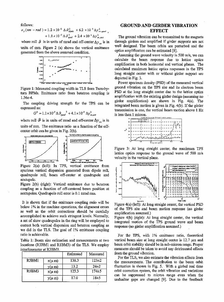
follows: ~ ~ ( n m - rad)=1 .2x lO" A$&,,e +6.2
where roll 9 is in units of mrad and off-centerAyco is in + l . l x 1 0 ~ 2 A L ~ d +2.4 x l O - ' A y ~ o ~ s ,
R3BMl x(pm) y(p m)
RlBM3 x(pm)
Y(P m)
units of mm. Figure 2 (a) shows the vertical emittance generated from the above assumed condition.
~~~
*.a - - . / B a t w
e.,.
0J.D
Q%, n a r a n u Z l O U l l P J a,.= ZIOl *ma w*Ba rwLL
Figure 1 : Measured coupling width in TLS from Turn-by- turn BPMs. Emittance ratio from betatron coupling is 1.56e-4.
The coupling driving strength for the TPS can be expressed as:
where roll 8 is in units of mrad and off-center Ayco is in units of mm. The emittance ratio as a function of the off- center orbit can be given in Fig. 2(b).
G~ = i . i X 1 0 - ~ ~ ~ ~ , , , 2 +4.iX10-~ ~ y ; ~ , +
YUI1PlniRbc.duD-CoUPlh. -,-*&s.*--
I " ' I I I
Estimated Measured 138.3 123*2 13.2 24h2 123.3 174*5 17.0 18*5
Figure 2(a) (left): In TPS, vertical emittance fiom spurious vertical dispersion generated fi-om dipole roll, quadrupole roll, beam off-center at quadrupole and sextupole. Figure 2@) (right): Vertical emittance due to betatron coupling as a function of off-centered beam position at sextupoles. Quadrupole roll error is 0.1 mrad rms.
It is shown that if the emittance coupling ratio will be below 1% in the machine operations, the alignment errors as well as the orbit corrections should be carefully accomplished to achieve such stringent levels. Normally, a set of skew quadrupoles in the ring will be employed to correct both vertical dispersion and betatron coupling as we did in the TLS. The goal of 1% emittance coupling ratio is achievable.
GROUND AND GIRDER VIBRATION EFFECT
The ground vibration can be transmitted to the magnets through girders and amplified if girder supports are not well designed. The beam orbits are perturbed and the optics amplification can be estimated [SI.
Assuming the ground wave velocity is 500 d s , we can calculate the beam response due to lattice optics amplification in both horizontal and vertical planes. The calculated maximum lattice optics responses in the TPS long straight center with or without girder support are depicted in Fig. 3.
Power spectrum density (PSD) of the measured vertical ground vibration on the TPS site and its electron beam PSD at the long straight center due to the lattice optics amplification with the existing girder design (assuming no girder amplification) are shown in Fig. 4(a). The integrated beam motion is given in Fig. 4@). If the girder transnzission is one, the vertical beam motion above 1 Hz is less than 1 micron.
P l . ~ Y . n a " , H z I
Figure 3: At long straight center, the maximum TPS lattice optics response to the ground wave of 500 d s velocity in the vertical plane.
Figure 4(a) (1eft):'At long straight center, the vertical PSD of the TPS site and beam motion response (no girder amplification assumed.) Figure 4@) (right): At long straight center, the vertical integrated motion of the TPS ground wave and beam response (no girder amplification assumed.)
For the TPS, with 1% emittance ratio, theoretical vertical beam size at long straight center is 12.7 pm and beam orbit stability should be in sub-micron range. Proper measures should be taken to avoid any detrimental effects from the ground vibration.
For the TLS, we.also estimate the vibration effects from the measurements. The contribution to the beam orbit fluctuation is shown in Fig. 5. With a global real time orbit correction system, the orbit vibration and variations can be suppressed to micron range even when the undualtor gaps are changed [9]. Due to the feedback

capability limitation, the gap change speed is restricted to ensure micron range beam orbit stability.
INSTABILITIES To suppress longitudinal coupled bunch instabilities
due to room temperature cavities in the TLS, we replaced the damping antenna with an adjustable plunger to control the strengths of the higher order modes, implementing a precision control of the cavity body temperature, and applied rf modulation. Acceptable stable beam is in the routine operations. However, if we want to increase stored beam current to 400 mA, we need to either add another rf system or replace it with a superconducting cavity. In 2004, we installed a CESR-type superconducting cavity module [l].
We have observed fast ion instabilities, especially in the vertical plane, since the operation of the storage ring in 1993 and the way to suppress it is to employ an active transverse damping system andor to leave a longer empty bucket train to allow the drift of ions away fiom the beam centre.
For the TPS, we plan to use superconducting RF cavities and coupled-bunch threshold is higher than nominal beam current at 400 mA. However, the onset of transverse instabilities induced by resistive wall might be at much lower current. In addition, the ion-beam instabilities are simulated and careful vacuum treatment as well as empty gap handling need to be taken care of [6]. The longitudinal coupled-bunch instabilities induced by cavity-like structures, as observed in the TLS, should be considered and the impedance budget control of the beam ducts is necessary.
90. ___- - - *__-- ~ - _ _ _ - - - -..U..,.-“.. --..--”..- -*“e
--.~.‘rrMu..ranu E-.F *e* .._______________________________________ *:----”- .,- ;------- Y e
Cr.ulrrn*.I
Figure 5: PSD and estimated vertical beam motion due to ground wave at TLS.
TANSVERSE AND LONGITUDINAL FEEDBACKS
New FPGA-based transverse and longitudinal bunch- by-bunch feedback systems have been commissioned recently [2]. After the replacement of the normal conducting cavities with a superconduting RF, the longitudinal instabilities are much reduced, but still some beam modes exit at high beam current, which might be due to the impedance of cavity-like beam ducts. The systems can effectively suppress the longitudinal and transverse beam instabilities and result in much stable bright beam. Figure 6 shows the transverse beam spectrum with and without transverse feedback and Fig. 7 depicts those for longitudinal spectrum. The contributions
to the enlargement of beam size due to energy oscillations are drastically reduced.
Figure 6: The transverse beam spectrum with and without transverse feedback
Figure 7: The longitudinal beam spectrum with and without longitudinal feedback. Some peaks are due to the bunch filling pattern, not the instabilities, in feedback case. Comparison with normal conducting cavity is given too.
CONCLUSION From the TLS operating experience, we learned that
control of vertical beam size need ‘vibration and ground motion damping, orbit and coupling correction, transverse and vertical feedback systems and global orbit feedback systems. The goal for the TPS is more stringent but it is doable. Thanks to S.Y. Lee for his suggestions in this study.
REFERENCES Ch. Wang, et al., “Successful Operation of the 500 MHz SRF Modules at TLSy,PAC 2005, pp. 3706- 3708. K.H. Hu, et al., “Commissioning of FPGA-Based Transverse and Longitudinal Bunch-by-Bunch Feedback System for the TLS’, BIW06, FNAL, May
G.H. Luo, et al., “The Implementation and Status of Quasi-constant Current Operation at the Taiwan Light Source”, this proceedings. C.C. Kuo, et al., ‘‘Coupling Correction Study at
C.H. Kuo, et al., “Upgrading the Orbit Feedback System in the Taiwan Light Source”, PAC 2003, pp.
C.C. Kuo, et al., ‘‘Design of Taiwan Future Synchrotron Light Source”, this proceedings. T.C. Tseng, et al, “The SRI Beam Size Monitor Developed at NSRRC“, PAC 2005, pp. 3465-3467, J. Rossbach, “Closed-Orbit Distortion of Periodic FODO Lattice due to Plane Ground Waves”, Part. Accel. 1988, Vol. 23, pp. 121-132. H.P. Chang, et al., “Operational Experience of the Insertion Devices and Expectation of the Future Superconducting Wigglers at NSRRC” PAC 2003, pp.
1-4,2006.
NSRRC‘’, PAC 2003, pp. 890-892.
3392-3394.
1044-1056.