vertical agitator - inoxpa de... · agitator operates with hot fluids (temperatures above 50ºc),...
TRANSCRIPT

INSTALLATION, SERVICE AND MAINTENANCE INSTRUCTIONS
VERTICAL AGITATOR
BMI
Original Manual
20.003.30.02EN
(0) 2019/02
20
.00
3.3
2.0
01
0
20.003.30.03EN
(0) 2019/02
(1) The serial number may be preceded by a slash and by one or two alphanumeric characters
20.003.30.03EN (0) 2019/02
EC Declaration of Conformity
We,
INOXPA, S.A.U.
Telers, 60
17820 – Banyoles (Girona)
Hereby declare under our sole responsibility that the machine
BMI VERTICAL AGITATOR
From serial number IXXXXXX to IXXXXXX (1)
/ XXXXXXXXXIIN to XXXXXXXXXIIN (1)
Fulfills all the relevant provisions of the following directive:
Machinery Directive 2006/42/EC
Low Voltage Directive 2014/35/UE
Electromagnetic Compatibility Directive 2014/30/UE
Applicable harmonized standards:
UNE-EN ISO 12100:2012
UNE-EN 14120:2016
The technical file has been prepared by the signer of this document in INOXPA.
David Reyero Brunet
Responsable Oficina Técnica
Banyoles, 7th February, 2019

INOXPA S.A.U. 20.003.30.02EN · (0) 2019/02 3
1. Table of Contents
1. Table of Contents
2. Generalities
2.1. Instructions manual ....................................................................................................................................... 4
2.2. Compliance with the instructions .................................................................................................................. 4
2.3. Warranty ........................................................................................................................................................ 4
3. Safety
3.1. Warning symbols .......................................................................................................................................... 5
3.2. General safety instructions ........................................................................................................................... 5
4. General Information
4.1. Description .................................................................................................................................................... 7
4.2. Operating principle ........................................................................................................................................ 7
4.3. Application ..................................................................................................................................................... 7
5. Installation
5.1. Reception of the agitator ............................................................................................................................... 8
5.2. Identification of the agitator ........................................................................................................................... 8
5.3. Transport and storage ................................................................................................................................... 9
5.4. Location ....................................................................................................................................................... 10
5.5. Electrical installation ................................................................................................................................... 10
5.6. Assembly ..................................................................................................................................................... 11
6. Start-up
7. Troubleshooting
8. Maintenance
8.1. General considerations ............................................................................................................................... 15
8.2. Maintenance................................................................................................................................................ 15
8.3. Lubrication ................................................................................................................................................... 15
8.4. Spare parts.................................................................................................................................................. 15
8.5. Conservation ............................................................................................................................................... 15
8.6. Disassembly and assembly of the agitator ................................................................................................. 16
9. Technical Specifications
9.1. Materials ...................................................................................................................................................... 18
9.2. Other features ............................................................................................................................................. 18
9.3. Weights ....................................................................................................................................................... 18
9.4. Dimesnions ................................................................................................................................................. 19
9.5. BMI Agitator with one bearing exploded drawing and parts list .................................................................. 20
9.6. BMI Agitator with two bearings exploded drawing and parts list ................................................................ 21

Generalities
4 INOXPA S.A.U. 20.003.30.02EN · (0) 2019/02
2. Generalities
2.1. INSTRUCTIONS MANUAL
This manual contains information about the reception, installation, operation, assembly, disassembly and maintenance of the BCI vertical agitator.
Carefully read the instruction prior to starting the agitator, familiarize yourself with the installation, operation and correct use of the agitator and strictly follow the instructions. These instructions should be kept in a safe location near the installation area.
The information published in the instruction manual is based on updated data.
INOXPA reserves the right to modify this instruction manual without prior notice.
2.2. COMPLIANCE WITH THE INSTRUCTIONS
Not following the instructions may impose a risk for the operators, the environment and the machine, and may result in the loss of the right to claim damages.
This non-compliance may result in the following risks:
Failure of important machine/plant functions.
Failure of specific maintenance and repair procedures.
Possible electrical, mechanical and chemical hazards.
Risk to the environment due to the type of substances released.
2.3. WARRANTY
Any warranty will be void immediately and lawfully and, additionally, INOXPA will be compensated for any civil liability claims submitted by third parties, in the following cases:
The service and maintenance work have not been carried out in accordance with the service instructions, the repairs have not been carried out by our personnel or have been carried out without our written authorisation.
Modifications have been carried out on our material or equipment without written authorisation.
The parts or lubricants used are not original INOXPA parts and products.
The material or equipment has been improperly used, has been used negligently, or has not been used according to the instructions and their intended.
The General Conditions of Delivery already in your possession are also applicable.
The machine may not undergo any modification without prior approval from the manufacturer. For your safety, only use original spare parts and accessories.
The usage of other parts will relieve the manufacturer of any liability.
Changing the service conditions can only be carried out with prior written authorization from INOXPA.
Please do not hesitate to contact us in case of doubts or if further explanations are required regarding specific data (adjustments, assembly, disassembly, etc.).
Safety
INOXPA S.A.U. 20.003.30.02EN · (0) 2019/02 5
3. Safety
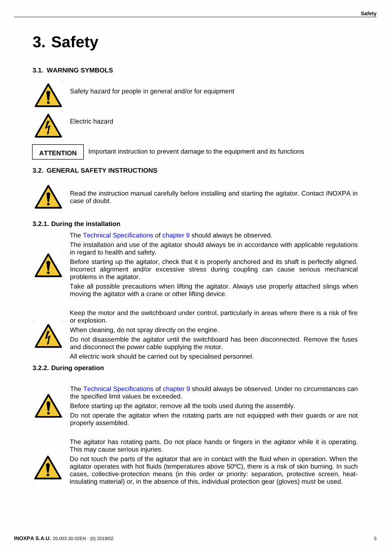
3.1. WARNING SYMBOLS
Safety hazard for people in general and/or for equipment Electric hazard
Important instruction to prevent damage to the equipment and its functions
3.2. GENERAL SAFETY INSTRUCTIONS
Read the instruction manual carefully before installing and starting the agitator. Contact INOXPA in case of doubt.
3.2.1. During the installation
The Technical Specifications of chapter 9 should always be observed.
The installation and use of the agitator should always be in accordance with applicable regulations in regard to health and safety.
Before starting up the agitator, check that it is properly anchored and its shaft is perfectly aligned. Incorrect alignment and/or excessive stress during coupling can cause serious mechanical problems in the agitator.
Take all possible precautions when lifting the agitator. Always use properly attached slings when moving the agitator with a crane or other lifting device.
Keep the motor and the switchboard under control, particularly in areas where there is a risk of fire or explosion.
When cleaning, do not spray directly on the engine.
Do not disassemble the agitator until the switchboard has been disconnected. Remove the fuses and disconnect the power cable supplying the motor.
All electric work should be carried out by specialised personnel.
3.2.2. During operation
The Technical Specifications of chapter 9 should always be observed. Under no circumstances can the specified limit values be exceeded.
Before starting up the agitator, remove all the tools used during the assembly.
Do not operate the agitator when the rotating parts are not equipped with their guards or are not properly assembled.
The agitator has rotating parts. Do not place hands or fingers in the agitator while it is operating. This may cause serious injuries.
Do not touch the parts of the agitator that are in contact with the fluid when in operation. When the agitator operates with hot fluids (temperatures above 50ºC), there is a risk of skin burning. In such cases, collective-protection means (in this order or priority: separation, protective screen, heat-insulating material) or, in the absence of this, individual protection gear (gloves) must be used.
ATTENTION
Safety
6 INOXPA S.A.U. 20.003.30.02EN · (0) 2019/02
The agitator and its installation can generate sound levels above 85 dB(A) under unfavourable operating conditions. In such cases, the operators must use devices for protection against noise.
3.2.3. During maintenance
The Technical Specifications of chapter 9 shall always be observed.
The agitator cannot operate without fluid. Standard agitators are not designed to work during the filling or emptying of tanks.
The maximum operating conditions of the agitator should not be exceeded. Nor should the operating parameters for which the agitator was initially designed be modified without written authorisations from INOXPA.
Do not leave loose parts on the floor.
Do not disassemble the agitator until the switchboard has been disconnected. Remove the fuses and disconnect the power cable supplying the motor.
All the electric work should be carried out by specialised personnel.
General Information
INOXPA S.A.U. 20.003.30.02EN · (0) 2019/02 7
4. General Information
4.1. DESCRIPTION
The BMI series range is vertical agitators with a stainless steel base and a lip seal as a sealing system. Although these agitators are very compact, they have a bearing bracket which is totally independent of the motor. The half shaft is guided by one or two bearings which withstand the axial and radial forces transmitted by the agitation element. The agitator shaft is directly attached to half shaft with two allen studs.
4.2. OPERATING PRINCIPLE
The agitators are usually installed off-centre to prevent product rotation but can also be installed centred in conjunction with deflector baffles in the tank.
The rotating propeller pushes the product towards the bottom of the tank, where it is diverted generating an upward flow along the tank walls so that the product reaches the surface of liquid. This effect is enhanced if the tank has a rounded base.
4.3. APPLICATION
The BMI vertical agitators can be used in mixing, dissolution, dispersion and maintenance processes requiring strong agitation at high speeds, as well as in the food processing, cosmetics and chemical industries selecting the appropriate finish in each case.
Applicable to tanks with capacities of up to 10.000 litres usually with low viscosity products.
Each agitator has performance limits. The agitator was selected for a given set of mixing conditions when the order was placed. INOXPA shall not be held responsible for any damage that might be suffered or malfunctioning of the equipment of the information provided by the buyer is incomplete or incorrect. (e.g. nature of the fluids or installation details).

Installation
8 INOXPA S.A.U. 20.003.30.02EN · (0) 2019/02
5. Installation
5.1. RECEPTION OF THE AGITATOR
INOXPA is not liable for any deterioration of the material caused by its transport or unpacking. Visually check that the packaging has not been damaged.
If the agitator is supplied without a drive or other element, the purchaser shall be responsible for its assembly, installation, start-up and operation.
When receiving the agitator, check the packaging and its content to ensure that it matches the delivery note. INOXPA packs the agitators in their fully assembled form or disassembled on a case-by-case basis. Ensure that the agitator has not been damaged in any way. If it is not in good condition and/or any parts are missing, the carrier must submit a report as soon as possible.
The following documentation is included with the agitator:
shipping documents,
instructions and Servicing manual for the agitator,
instructions and Servicing manual for the gear-motor when the agitator is supplied with a motor by INOXPA.
5.2. IDENTIFICATION OF THE AGITATOR
The agitator is identified using a rating plate fixed onto the motor. The type of agitator and the serial number appear on the nameplate.
Serial number
20
.00
3.3
2.0
00
9

Installation
INOXPA S.A.U. 20.003.30.02EN · (0) 2019/02 9
BMI 1. 10 - 4 011 - 1 - 150
Diameter of the agitation element
150 150 mm
160 160 mm
175 175 mm
200 200 mm
225 225 mm
Motor
1 IP-55
2 IP-65
3 Flameproof
4 Explosion-proof
5 Single phase
Motor power
007 0,75 kW
011 1,1 kW
015 1,5 kW
022 2,2 kW
030 3 kW
040 4 kW
055 5,5 kW
Motor speed
4 poles 1.500 rpm
6 poles 1.000 rpm
Type of agitation elements
10 Marine type
4 Sawtooth type
Number of agitation elements
1 One agitation element
2 Two agitation elements
Name of the agitator
BMI Vertical agitator with motor
5.3. TRANSPORT AND STORAGE
According to the model, the agitators are too heavy to be stored or installed manually. Use an appropriate mode of transport. Do not handle the agitator by the shaft as this may become deformed.
ATTENTIONNN
Installation
10 INOXPA S.A.U. 20.003.30.02EN · (0) 2019/02
Take all possible precautions when lifting the agitator. Always use properly attached slings when moving the agitator with a crane or other lifting device.
If the agitator is not to be installed immediately, it must be stored in an appropriate place. The shaft must be stored in a horizontal position and placed on wooden supports or for a similar material. In this position, the shaft will not become deformed but it must not be subject to any type of load.
5.4. LOCATION
Place the agitator in such a way as to facilitate inspections and checks. Leave enough room around the agitator for service, disassembly and maintenance operations. It is very important to be able to access the electric connection device of the agitator, even when in operation.
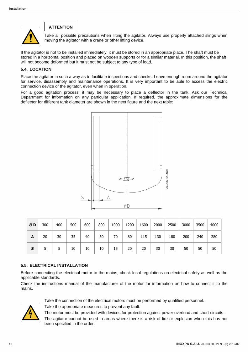
For a good agitation process, it may be necessary to place a deflector in the tank. Ask our Technical Department for information on any particular application. If required, the approximate dimensions for the deflector for different tank diameter are shown in the next figure and the next table:
5.5. ELECTRICAL INSTALLATION
Before connecting the electrical motor to the mains, check local regulations on electrical safety as well as the applicable standards.
Check the instructions manual of the manufacturer of the motor for information on how to connect it to the mains.
Take the connection of the electrical motors must be performed by qualified personnel.
Take the appropriate measures to prevent any fault.
The motor must be provided with devices for protection against power overload and short-circuits.
The agitator cannot be used in areas where there is a risk of fire or explosion when this has not been specified in the order.
D 300 400 500 600 800 1000 1200 1600 2000 2500 3000 3500 4000
A 20 30 35 40 50 70 80 115 130 180 200 240 280
S 5 5 10 10 10 15 20 20 30 30 50 50 50
ATTENTION
20
.00
5.3
2.0
00
3
Installation
INOXPA S.A.U. 20.003.30.02EN · (0) 2019/02 11
5.6. ASSEMBLY
To locate and fix the agitator in the support flange of the tank, the propeller must be removed from the shaft. Once the base of the agitator is placed on the supporting flange, the fixing nuts and screws will be assembled in their corresponding holes, without being tightened. When this operation has been carried out, the agitator must be levelled using the following method:
1. Place a spirit level against the shaft. 2. Check 4 points at 90º to each other around the circumference of the shaft and at the same height. 3. Once the shaft is level, firmly tighten the fixing nuts and screws. Finally the propeller is mounted on the
end of the shaft. Be careful when assembling the shaft not to hit or strain it so as to avoid it being bent.
Force should never be applied to the end of the agitator shaft, as it can easily suffer permanent damage.
Check the alignment of the agitator shaft with the half shaft once its assembly is completed.
ATTENTION
ATTENTION
Start-up
12 INOXPA S.A.U. 20.003.30.02EN · (0) 2019/02
6. Start-up
The start-up of the agitator can be carried out provided the instructions indicated in the chapter 5. Installation have been followed.
Check that the power supply matches the rating indicated on the motor plate.
Check the alignment of the agitator shaft.
Check the level of fluid in the tank. When not specified in the order, the agitator cannot be operated during the filling or emptying of the tank.
The agitator can NEVER operate without fluid. The agitation elements may only be submerged to a height equal to 1,5 times its diameter.
All the guards must be in place.
Start up the agitator.
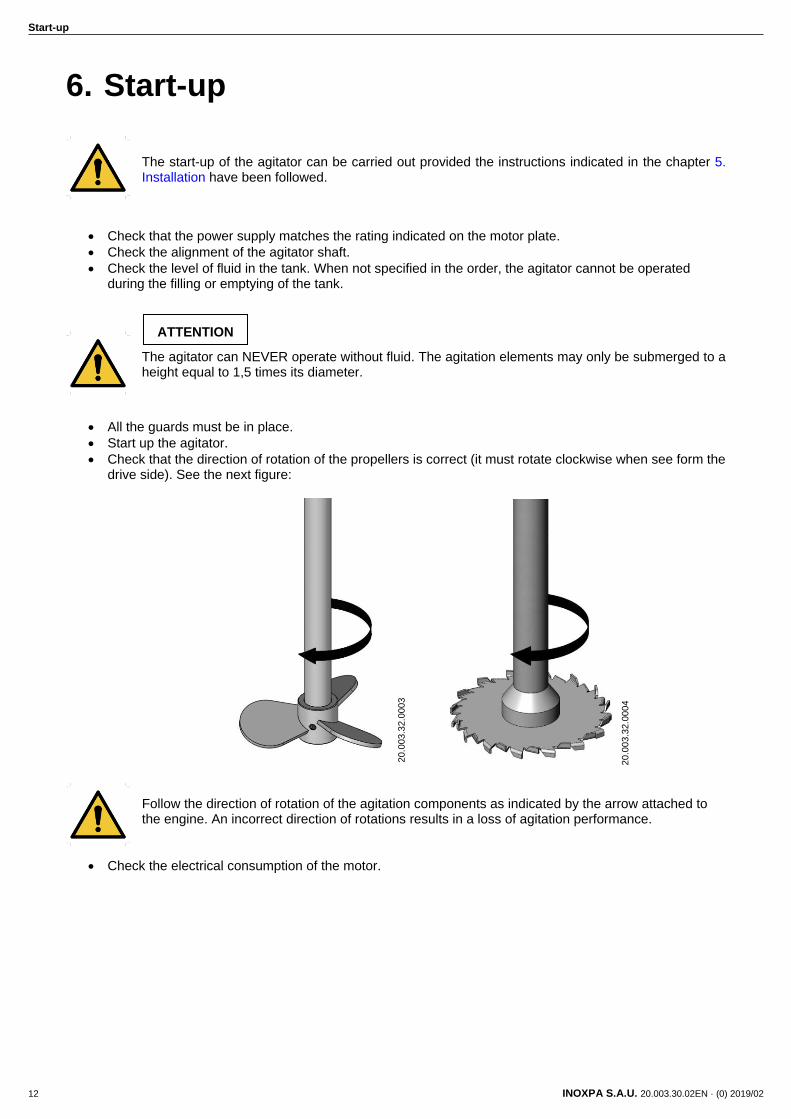
Check that the direction of rotation of the propellers is correct (it must rotate clockwise when see form the drive side). See the next figure:
Follow the direction of rotation of the agitation components as indicated by the arrow attached to the engine. An incorrect direction of rotations results in a loss of agitation performance.
Check the electrical consumption of the motor.
ATTENTION
20
.00
3.3
2.0
00
3
20
.00
3.3
2.0
00
4
Start-up
INOXPA S.A.U. 20.003.30.02EN · (0) 2019/02 13
Do not modify the operating parameters for which the agitator was initially designed without written authorisation from INOXPA (risk of damage and user hazard).
Follow the instructions for use and the safety requirements described in the instructions manual for the tank in which the agitator is mounted.
Mechanical risks (e.g. drag, shear, cutting, impact, flattening and pinching). If the agitation element is accessible from the top or the tank inspections hatch, then the user will be exposed to the above-mentioned risks.
The tank must be fitted with protective devices and safety equipment. Consult the manufacturer’s instructions manual.
Introducing an object or solid raw material may cause the agitation component and other mechanical parts to break and compromise its safety or guarantee.
ATTENTION
ATTENTION

Troubleshooting
14 INOXPA S.A.U. 20.003.30.02EN · (0) 2019/02
7. Troubleshooting
The attached table lists solutions to problems that may arise while operating the agitator. It is assumed that the agitator has been properly installed and that is has been selected correctly for the specific application.
Contact INOXPA if technical assistance is required.
Motor overload
Insufficient agitation
Vibrations and noise
Leaks
PROBABLE CAUSES SOLUTIONS
Viscosity of the liquid too high Reduce the viscosity, e.g. by heating the liquid
High density Increase motor power
Tank too big for the chosen agitator Check with the technical department
Wrong direction of rotation Change direction of rotation
Agitator speed too low Increase the speed
Liquid level insufficient or none Check liquid level in the tank
Shaft bended Replace the shaft
Critical speed Check with the technical department
Worn bearings Replace the bearings agitator
Lip seal worn or damaged
If the lip seal is worn, replace it.
If the lip seal is damaged, consult the technical department.
If the problems persist stop using the agitator immediately. Contact the agitator manufacturer or the representative.
Maintenance
INOXPA S.A.U. 20.003.30.02EN · (0) 2019/02 15
8. Maintenance
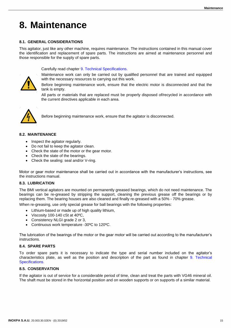
8.1. GENERAL CONSIDERATIONS
This agitator, just like any other machine, requires maintenance. The instructions contained in this manual cover the identification and replacement of spare parts. The instructions are aimed at maintenance personnel and those responsible for the supply of spare parts.
Carefully read chapter 9. Technical Specifications.
Maintenance work can only be carried out by qualified personnel that are trained and equipped with the necessary resources to carrying out this work.
Before beginning maintenance work, ensure that the electric motor is disconnected and that the tank is empty.
All parts or materials that are replaced must be properly disposed of/recycled in accordance with the current directives applicable in each area.
Before beginning maintenance work, ensure that the agitator is disconnected.
8.2. MAINTENANCE
Inspect the agitator regularly.
Do not fail to keep the agitator clean.
Check the state of the motor or the gear motor.
Check the state of the bearings.
Check the sealing: seal and/or V-ring.
Motor or gear motor maintenance shall be carried out in accordance with the manufacturer’s instructions, see the instructions manual.
8.3. LUBRICATION
The BMI vertical agitators are mounted on permanently greased bearings, which do not need maintenance. The bearings can be re-greased by stripping the support, cleaning the previous grease off the bearings or by replacing them. The bearing houses are also cleaned and finally re-greased with a 50% - 70% grease.
When re-greasing, use only special grease for ball bearings with the following properties:
Lithium-based or made up of high quality lithium,
Viscosity 100-140 cSt at 40ºC,
Consistency NLGI grade 2 or 3,
Continuous work temperature -30ºC to 120ºC.
The lubrication of the bearings of the motor or the gear motor will be carried out according to the manufacturer’s instructions.
8.4. SPARE PARTS
To order spare parts it is necessary to indicate the type and serial number included on the agitator’s characteristics plate, as well as the position and description of the part as found in chapter 9. Technical Specifications.
8.5. CONSERVATION
If the agitator is out of service for a considerable period of time, clean and treat the parts with VG46 mineral oil. The shaft must be stored in the horizontal position and on wooden supports or on supports of a similar material.

Maintenance
16 INOXPA S.A.U. 20.003.30.02EN · (0) 2019/02
8.6. DISASSEMBLY AND ASSEMBLY OF THE AGITATOR
The disassembly and assembly of the agitators should only be carried out by qualified personnel using only appropriate tools. Ensure that staff read these instructions manual attentively, particularly the instructions that relate to their work.
Stop the motor from starting up when carrying out assembly and disassembly work on the agitator.
Place the agitator switch in the “off” position.
Lock out the electrical switchboard or place a warning sign.
Remove the fuses and take them to the workplace.
8.6.1. Disassembly of the agitator
Once the motor has been disconnected, disassembly work of the agitator may begin: - Agitator with bearing support with one ball bearing:
Take the agitator out of the tank
Remove the marine propeller (02) from the agitator shaft (05), unscrewing the allen studs (55).
Remove the agitator shaft (05) from the half-shaft (26) through the allen studs (55A).
Remove the hexagonal screws (52) and flat washers (53) and take out the motor (93).
Remove the countersunk screws (50). Hit the upper part of the half-shaft (26) with a nylon hammer and take out the unit formed by the half-shaft (26), ball bearing (70), base plate (42), lip seal (88) and bearing stop ring (31).
Once in the outside of the bearings support, remove the base plate (42) from the half-shaft (26) and with the aid of a nylon hammer remove the lip seal (88).
Take off the elastic ring (66) with a suitable pliers and remove the ball bearing (70) with a press. See figure 8.1
- Agitator with bearing support with two ball bearing:
On the sawtooth propeller (02), remove the hexagonal screw (52A). Once extracted it, leave the propeller bucket (02A) with the dragging pivots (02C), the sawtooth propeller (02) and the washer (02B).
Remove the hexagonal screws (52) and flat washers (53), and take out the motor (93).
Remove the countersunk screws (50). Hit the upper part of the agitator shaft (05) with nylon hammer and take out the unit formed by the agitator shaft (05), ball bearings (70, 70A), base plate (42), lip seal (88) and bearing stop ring (31).
Once in the outside of the bearings support, remove the base plate (42) from the agitator shaft (05) and with the aid of a nylon hammer remove the lip seal (88).
Take off the elastic ring (66) of the upper ball bearing with suitable pliers and remove the upper ball bearing (70A) with a press. Then, remove the other elastic rings (66) and proceed to disassembly the bottom ball bearing (70) with a press. See figure 8.1.
20
.00
3.3
2.0
00
5
Figure 8.1

Maintenance
INOXPA S.A.U. 20.003.30.02EN · (0) 2019/02 17
8.6.2. Assembly of the agitator
Put the bearing stop ring (31) and the lip seal (88) in the base plate (42).
Next proceed to disassembly of bearings according to the case.
- Agitator with bearing support with one ball bearing:
Fit the ball bearing (70) and the elastic ring (66) on the half-shaft (26).
After the half shaft/ball bearing unit has been assembled, put it in the bearings support by the base plate side until it is positioned. Fit the unit of base plate (42), bearing stop ring (31) and lip seal (88) on the half shaft. Fit all through the countersunk screws (50).
Mount the motor (93) on the bearing support (06) and fix it with the hexagonal screws (52) and flat washers (53).
Joint the agitator shaft (05) with the half shaft using the allen studs (55A).
Place the marine propeller (02) in the agitator shaft and tighten the allen studs (55).
Fit the agitator over the tank.
- Agitator with bearing support with two ball bearing:
Fit the lower elastic ring (66) of bottom ball bearing (70) with suitable pliers. Enter the bottom ball bearing (70) through the top part of the agitator shaft (05), and fix it through the elastic ring (66). Then repeat the same way for the upper ball bearing (70A).
After the shaft and ball bearings unit has been assembled, put it in the bearings support by the base plate side until it is positioned. Fit the unit of base plate (42), bearing stop ring (31) and lip seal (88) on the agitator shaft (05). Fit all through the countersunk screws (50).
Mount the motor (93) on the bearing support (06) and fix it with the hexagonal screws (52) and flat washers (53).
Place the sawtooth propeller (02). Firstly, put the propeller bucket (02A) with dragging pivots (02C) at the end of the shaft. Locate the holes of the sawtooth propeller (02) with dragging pivots (02C). The direction of rotation must consider. Next, locate the holes of the washer (02B) with the dragging pivots (02C) and, finally, tightening the hexagonal screw (52A).
Fit the agitator over the tank.

Technical Specifications
18 INOXPA S.A.U. 20.003.30.02EN · (0) 2019/02
9. Technical Specifications
9.1. MATERIALS
Parts in contact with the product AISI 316L
Other steel parts AISI 304
Retainer NBR
Bearing support AISI 316L
Surface finish Ra ≤ 0,8 μm (except sawtooth propeller)
9.2. OTHER FEATURES
Motor IEC B5, IP 55, F class insulation
Speed (rpm) 1.000 – 1.500
Motor power (kW) 4
Shaft length (mm) 1.400 – 1.500
Shaft diameter (mm) 20 - 45
Propeller diameter (mm) 150 – 225
Propeller Marine propeller (type 10) – Sawtooth propeller (type 4)
9.3. WEIGHTS
Type agitator Weigh (kg)
BMI 1.10-4011-1-160 30
BMI 1.10-4015-1-175 33
BMI 1.10-4030-1-200 41
BMI 1.10-4055-1-225 57
BMI 1.10-6007-1-175 30
BMI 1.10-6011-1-200 33
BMI 1.10-6015-1-225 42
BMI 1.4-4022-1-150 38
BMI 1.4-4040-1-200 44

Technical Specifications
INOXPA S.A.U. 20.003.30.02EN · (0) 2019/02 19
9.4. DIMENSIONS
Type agitator
Dimensions (mm)
A B C
BMI 1.10-4011-1-160 160 1.915 270
BMI 1.10-4015-1-175 175 1.915 295
BMI 1.10-4030-1-200 200 1.943 325
BMI 1.10-4055-1-225 225 1.946 350
BMI 1.10-6007-1-175 175 1.915 270
BMI 1.10-6011-1-200 200 1.915 295
BMI 1.10-6015-1-225 225 1.943 325
BMI 1.4-4022-1-150 150 2.043 325
BMI 1.4-4040-1-200 200 2.046 350
20
.00
3.3
2.0
00
6
Technical Specifications
20 INOXPA S.A.U. 20.003.30.02EN · (0) 2019/02
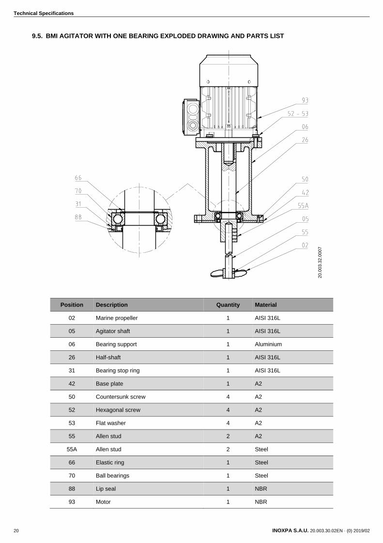
9.5. BMI AGITATOR WITH ONE BEARING EXPLODED DRAWING AND PARTS LIST
Position Description Quantity Material
02 Marine propeller 1 AISI 316L
05 Agitator shaft 1 AISI 316L
06 Bearing support 1 Aluminium
26 Half-shaft 1 AISI 316L
31 Bearing stop ring 1 AISI 316L
42 Base plate 1 A2
50 Countersunk screw 4 A2
52 Hexagonal screw 4 A2
53 Flat washer 4 A2
55 Allen stud 2 A2
55A Allen stud 2 Steel
66 Elastic ring 1 Steel
70 Ball bearings 1 Steel
88 Lip seal 1 NBR
93 Motor 1 NBR
20
.00
3.3
2.0
00
7
Technical Specifications
INOXPA S.A.U. 20.003.30.02EN · (0) 2019/02 21
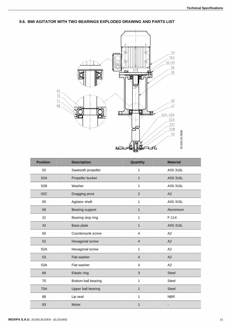
9.6. BMI AGITATOR WITH TWO BEARINGS EXPLODED DRAWING AND PARTS LIST
Position Description Quantity Material
02 Sawtooth propeller 1 AISI 316L
02A Propeller bucket 1 AISI 316L
02B Washer 1 AISI 316L
02C Dragging pivot 2 A2
05 Agitator shaft 1 AISI 316L
06 Bearing support 1 Aluminium
31 Bearing stop ring 1 F-114
42 Base plate 1 AISI 316L
50 Countersunk screw 4 A2
52 Hexagonal screw 4 A2
52A Hexagonal screw 1 A2
53 Flat washer 4 A2
53A Flat washer 4 A2
66 Elastic ring 3 Steel
70 Bottom ball bearing 1 Steel
70A Upper ball bearing 1 Steel
88 Lip seal 1 NBR
93 Motor 1 -
20
.00
3.3
2.0
00
8

NOTES
________________________________________________________________________________
________________________________________________________________________________
________________________________________________________________________________
________________________________________________________________________________
________________________________________________________________________________
________________________________________________________________________________
________________________________________________________________________________
________________________________________________________________________________
________________________________________________________________________________
________________________________________________________________________________
________________________________________________________________________________
________________________________________________________________________________
________________________________________________________________________________
________________________________________________________________________________
________________________________________________________________________________
________________________________________________________________________________
________________________________________________________________________________
________________________________________________________________________________
________________________________________________________________________________
________________________________________________________________________________
________________________________________________________________________________
________________________________________________________________________________
________________________________________________________________________________
________________________________________________________________________________
________________________________________________________________________________
________________________________________________________________________________
________________________________________________________________________________
________________________________________________________________________________
________________________________________________________________________________

INOXPA S.A.U.
Telers, 60 – 17820 – Banyoles – Spain
Tel.: +34 972 575 200 – Fax: +34 972 575 502
How to contact INOXPA S.A.U.:
Contact details for all countries are
continually updated on our website.
Please visit www.inoxpa.com to access the information.
20.0
03.3
0.0
2E
N ·
(0)
20
19/0
2