version 3.3 | 2017-12-11 english - home: lightpower€¦ · 000 3. introduction ma lighting´s...
TRANSCRIPT

Version 3.3 | 2017-12-11 English
1

© 2017 MA Lighting Technology GmbH | Dachdeckerstr. 16 | D-97297 Waldbüttelbrunn | GermanyPhone +49 5251 688865-30 | tech.support (at)malighting.com | www.malighting.com
Version 3.3
1
1. 4
2. 5
3. 6
4. 7
4.1. 7
4.2. 8
4.3. 8
5. 9
5.1. 9
5.2. 10
5.3. 11
6. 12
6.1. 12
6.2. 13
7. 14
7.1. 14
7.2. 22
7.3. 24
7.4. 29
7.5. 32
7.6. 33
7.7. 34
7.8. 34
7.9. 35
7.10. 37
7.11. 37
7.12. 38
8. 41
9. 45
9.1. 46
9.2. 49
9.3. 49
Table of contentsHelp From MA Technical Support
Symbols Used
Introduction
Install and Uninstall
System Requirements
Installation
Uninstall MA 3D
First Steps
Hardware connection
Start MA 3D
Create a Session
Data Management
Master/Slave
Coordinate system
Program Surface
Menu Bar
Tool Bar
Main Windows
Assets (Information Window)
Properties
Media Database
Materials
Video Player
Moving Paths
Sessions
Status Bar
Windows Layout
Fixture Types
3D Modeling and Import
Workflow
3D Models Principles
Creation of a 3D Model
2

© 2017 MA Lighting Technology GmbH | Dachdeckerstr. 16 | D-97297 Waldbüttelbrunn | GermanyPhone +49 5251 688865-30 | tech.support (at)malighting.com | www.malighting.com
Version 3.3
1
9.4. 53
9.5. 60
9.6. 63
9.7. 64
9.8. 64
9.9. 67
10. 73
11. 74
12. 75
Creation of a 3D Fixture Model
Import 3D Model to MA3D
Assigning of Models to Fixture Types
Checklist for 3D Modeling
Automated Import
Parameters
Keyboard Shortcuts
MA 3D FAQ
Index
3

© 2017 MA Lighting Technology GmbH | Dachdeckerstr. 16 | D-97297 Waldbüttelbrunn | GermanyPhone +49 5251 688865-30 | tech.support (at)malighting.com | www.malighting.com
Version 3.3
1
1. Help From MA Technical Support
If the MA 3D is not working as described in the manual, you can take the following steps:
Error message: You cannot proceed with the next step of the description and you receive an error message:Refer to Error Messages and repeat the procedure.If the problem is still there, contact the technical support.
System is not working: If you cannot proceed with the next step of the description and you do not receive anerror message:Contact the technical support and describe the last steps you took.
Technical Service and Support
MA Lighting and its extensive distributor network offer an unparalleled technical service.Call on our expertise for help with any problem, no matter if it is regarding operation, software features, softwareinstallations or trouble shooting.
Please send an email (in English or German) to the tech support with your contact details and the technicalquestion. See the email address of the technical support in the footer of this website.This email service is monitored during MA Lighting's regular business hours in Germany from 8.30 a.m. until 5 p.m.,Monday through Friday.
For emergency services please contact your local MA distributor or the MA Lighting Service Hotline.Call: +49 5251 688865-99. Please note that this is a 24/7 hotline which is used for emergency cases only. Usethis hotline only if troubles occur shortly before an upcoming event.
4

© 2017 MA Lighting Technology GmbH | Dachdeckerstr. 16 | D-97297 Waldbüttelbrunn | GermanyPhone +49 5251 688865-30 | tech.support (at)malighting.com | www.malighting.com
Version 3.3
1
2. Symbols Used
The following symbols display possible danger, useful hints and information when using the device.
Warning:The warning sign displays possible injury and hazard.
Restriction:The restriction sign displays known limitations of functions.
Information:The information sign displays possible damage of device.
Hint:The hint sign displays additional hints when using the console.
5

© 2017 MA Lighting Technology GmbH | Dachdeckerstr. 16 | D-97297 Waldbüttelbrunn | GermanyPhone +49 5251 688865-30 | tech.support (at)malighting.com | www.malighting.com
Version 3.3
1
3. Introduction
MA Lighting´s visualizer and preprograming studio – the PC software MA 3D – is an extremely powerful tool createdfor the visualization and design of three-dimensional stage layouts. Conventional and moving light fixtures can bedisplayed together with any grandMA2 console or the grandMA2 onPC program.
MA 3D allows a straight forward design and setup of any custom stage or scenery layout with its 2D drawing facilitiesand a library of basic graphical elements. Multiple windows – both in 2D or 3D view with any camera angle – canbe opened simultaneously and are updated in real time. All stage elements can be positioned in x, y, z directionsand can also be rotated about their axes. This equipment can be moved freely in the 3D space via the grandMA2console.
One of the many advantages of MA 3D is that it is stored in the same show file in the grandMA2 system. No matterwhere you are or what type of grandMA2 console or MA equipment you use you always have the complete show filewith you!
The MA 3D application runs on powerful Windows® PCs and communicates with the grandMA2 console vianetwork.
6

© 2017 MA Lighting Technology GmbH | Dachdeckerstr. 16 | D-97297 Waldbüttelbrunn | GermanyPhone +49 5251 688865-30 | tech.support (at)malighting.com | www.malighting.com
Version 3.3
1
4. Install and UninstallSystem Requirements
Installation
Uninstall
4.1. System Requirements
If you want to run MA 3D on your PC, here's what it takes.
Minimum Recommended Operating system Windows® 7
Windows® 8 Windows® 8.1 Windows® 10 all with admin rights Processor Dual Core 2.4 gigahertz (GHz) Intel i7
CPU or faster with support SSE2 RAM 2 gigabyte (GB) 8 GB
Hard disk 32 GB available space type SSD
Graphic card 3D with hardware acceleration 3GB graphic RAM
and 1024 MB Vertex Shader Version 3.0 or greater Pixel Shader Version 3.0 or greater Resolution 1024 x 768 or higher 1920 x 1080
Network card 100/1000 TX/T Gigabit-Ethernet
IBM® compatible PC or notebook is necessary.
Additional requirements for the use of certain features:
To use the online help and to download the latest version of MA 3D, you need internet access.
To save to a USB stick, you need a USB 2.0 or 3.0 port.
We recommend that you visit your PC manufacturer´s website for information about updated drivers and hardwarecompatibility.
4.2. Installation
7

© 2017 MA Lighting Technology GmbH | Dachdeckerstr. 16 | D-97297 Waldbüttelbrunn | GermanyPhone +49 5251 688865-30 | tech.support (at)malighting.com | www.malighting.com
Version 3.3
1
4.2. Installation
Download the latest version from http://www.malighting.com.
The installation is possible in every root directory or in the standard directory "MA Lighting Technologies\MA 3D" inthe folder "program".
The different versions of the MA 3D are independent programs. There is no need to install or uninstall older versions.
It is possible to open shows from an older version in the newer version.
Shows saved in a newer version cannot opened in an older version.
Information:You should have administration rights to install the program.
Installation on your PC:
If you downloaded only the MA 3D, start the installation file MA3D_vx.x.x.x.exe with a double click.
If you downloaded the MA software release package, extract the file into a temporary folder and start the installationfile MA3D_vx.x.x.x.exe with a double click.
On the screen appears the installation program. You get detailed hints and information regarding the installation.
Watch out for the suggested directory and change it if you want to. The installation directory is not changeable inthe program.
4.3. Uninstall MA 3D
The following topic describes how to uninstall MA 3D.
With the uninstall.exe you remove the MA 3D from your computer.
All created directories and program data in the start menu will be removed.
All files stored by you and which are not part of the installation file, especially the show files, will be kept in the
folder program data. This folder is hidden by default from Windows®.
1. Click the Start button, click All Programs, click MA Lighting, click MA 3D v.x.x.x.x, and click Uninstall MA3D v.x.x.x.x.If you are prompted for an administrator password or confirmation, type the password or provide confirmation.A pop-up asks, if you really want to uninstall MA 3D.
2. Click Yes.A pop-up confirms that MA 3D v.x.x.x.x is uninstalled.
3. Click OK.
8

© 2017 MA Lighting Technology GmbH | Dachdeckerstr. 16 | D-97297 Waldbüttelbrunn | GermanyPhone +49 5251 688865-30 | tech.support (at)malighting.com | www.malighting.com
Version 3.3
1
5. First Steps
This chapter describes how you prepare the MA 3D for the usage.
The installation process creates a desktop link called MA 3D v.x.x.x.x
To start the MA 3D, double click on the desktop link.
Additional it creates a folder in the start menu (Start - Programs - MA Lighting).
To start the MA 3D from the start menu, click on MA 3D v.x.x.x.x .
5.1. Hardware connection
This topic describes how to connect a computer and a grandMA2 console. If you want to create a session betweenthe MA 3D and the grandMA2 console, you need a hardware connection.
Requirement: Network cable or switch.
Connect the console and the computer with a network cable or switch, refer to Console Backpanel.
grandMA2 Console:
Network Cable or Switch:
Computer:
The grandMA2 console and the computer are connected.
5.2. Start MA 3D
9

© 2017 MA Lighting Technology GmbH | Dachdeckerstr. 16 | D-97297 Waldbüttelbrunn | GermanyPhone +49 5251 688865-30 | tech.support (at)malighting.com | www.malighting.com
Version 3.3
1
5.2. Start MA 3D
After installation start the MA 3D.
The installation process creates a desktop link called MA 3D v.x.x.x.x .
To start the MA 3D, double click on the desktop link.
Additional it creates a folder in the start menu (Start - Programs - MA Lighting).
To start the MA 3D from the start menu, click on MA 3D v.x.x.x.x .
Open an existing showfile in MA 3D
Hint:If you are in a session with a grandMA2 console/onPC there is no need to open showfiles via the MA 3D.Open the showfile directly in the Backup Menu of the grandMA2 console/onPC.
1. Open the Load Show Window "File - Load Show".
Information:Showfiles saved in an older version of MA 3D can always be opened in a newer version.Showfiles saved in a newer version of MA 3D cannot opened in an older version.
2. Select a showfile and click OK.You opened an existing showfile.
It is not possible to start a session from MA 3D and transfer the showfile to the desk.This is only possible if a session with the desk or onPC is already running.
5.3. Create a Session
10

© 2017 MA Lighting Technology GmbH | Dachdeckerstr. 16 | D-97297 Waldbüttelbrunn | GermanyPhone +49 5251 688865-30 | tech.support (at)malighting.com | www.malighting.com
Version 3.3
1
5.3. Create a Session
Creating, joining a MA session, or inviting session members is an exclusive grandMA2 console or grandMA2 onPCfeature.
Requirement: Hardware connection between a grandMA2 console and a computer, or a grandMA2 onPC and a MA
3D.
Sessions can be created from grandMA2 console/onPC only, refer to MA Network Configuration - 3D.
Information:The software version of the MA 3D and the console/onPC needs to be the same.MA 3D v.3.0.0.5 fits to grandMA2 console or onPC version 3.0.0.Important are the first 3 numbers. If you have different version numbers, there is no connection possible.Download the latest software version at www.malighting.com.
Information:The IP addresses of the MA 3D and of the grandMA2 console/onPC have to fit. The first three sets ofnumbers have to be the same. The last number is different.The default IP address of the MA 3D is 127.0.0.1. The default IP address from the MA 3D fits with thedefault address of the grandMA onPC.If the IP address of the MA 3D and of the grandMA2 console/onPC is not the same, there is no networkconnection.To double check the IP address of the grandMA2 console/onPC, refer to Seting the IP address in theconsole.
11

© 2017 MA Lighting Technology GmbH | Dachdeckerstr. 16 | D-97297 Waldbüttelbrunn | GermanyPhone +49 5251 688865-30 | tech.support (at)malighting.com | www.malighting.com
Version 3.3
1
6. Data Management
This section describes how data is managed by the grandMA2 console and the MA 3D visualizer. Both can workindependently. If they are connected in a MA network session the grandMA2 console will be the master and send thecurrent showfile to the connected MA 3D. Data changed within MA 3D is transferred to the grandMA2 console andvice versa. MA 3D and the grandMA2 console use the same show files (.show.gz).
6.1. Master/Slave
Creating an MA session, or inviting session members is an exclusive grandMA2 console or onPC feature. If thegrandMA2 console is connected and a session is started within the console, the show file will be transferred to the3D. So the synchronization of the grandMA2 console and the MA 3D data is guaranteed. The 2 possible states of theconnection are indicated by the heart in the status bar. The blinking of the heart indicates the communicationbetween the grandMA2 console and the MA 3D.
Heart is broken and red: MA 3D has not joined a session. The connection state is 'Standalone'.
Heart is blinking green: MA 3D has joined a session. The connection state is 'Slave'.
Information:With the start of a new session (Create) the session founder (grandMA2 console or onPC) overwrites alldata of the other members. Inviting can be disabled by changing the state of the button "Invite Enabled"to "Invite Disabled" in the sessions window.
6.2. Coordinate system
12

© 2017 MA Lighting Technology GmbH | Dachdeckerstr. 16 | D-97297 Waldbüttelbrunn | GermanyPhone +49 5251 688865-30 | tech.support (at)malighting.com | www.malighting.com
Version 3.3
1
6.2. Coordinate system
MA 3D geometric system lets you define and manipulate objects in 3D space. It features a geometric systemarchitecture that defines the X-Y plane as the ground area with the height as Z -axis. All objects can be moved orrotated along the world- or their own object axis (if the object has been rotated) as described in chapter StageView. You can switch between the world or object axis via a toolbar button or the keyboard as shown in thefollowing list:
Operating Elements Symbols in 3D View Description
World axis
or Ctrl + W
Objects can be moved
along the world axis.
Objects can be rotated
along the world axis.
Object axis
or Ctrl +O
Objects can be moved
along the object axis.
Objects can be rotated
along the object axis.
13

© 2017 MA Lighting Technology GmbH | Dachdeckerstr. 16 | D-97297 Waldbüttelbrunn | GermanyPhone +49 5251 688865-30 | tech.support (at)malighting.com | www.malighting.com
Version 3.3
1
7. Program Surface
The program surface is structured in five areas.
Menu Bar with different submenus for the most functions of the program.
Tool Bar below the menu bar.
View Area displays additional views.
Status Bar with the status regarding your network.
Main View visualize your show and displays the 3D Objects Window.
MA 3D - Program surface
7.1. Menu Bar
With the menu bar, you get access to the most features of the program.
Many features you can also reach with the toolbar, shortcuts or the context menu.
If you press Alt, some letters in the menu bar will be underlined. If you press Alt + the underlined letter, the menuopens.
7.1.1. Menu Bar - File Menu
14

© 2017 MA Lighting Technology GmbH | Dachdeckerstr. 16 | D-97297 Waldbüttelbrunn | GermanyPhone +49 5251 688865-30 | tech.support (at)malighting.com | www.malighting.com
Version 3.3
1
7.1.1. Menu Bar - File Menu
The file menu in detail.
File menu
New Show Creates a new show.LoadShow...
Opens the Load Show window.
RecentFiles
Displays the recent opened show files.
Save ShowSaves the current show with the given filename. The show will also be saved on all connecteddesks or onPCs.
SaveShow As…
Opens the windows explorer to save the current show with a new filename. The show will also besaved on all connected desks or onPCs.
Import The following options are available: - Import Environment. Opens the window explorer to import an environment from a show file. - Import 3D Model. Opens the MA 3D - Import Window. Refer to, 3D Modeling and Import.Export Opens the windows explorer to export an environment to a show file.Settings… Opens the MA 3D Settings. Refer to: Menu Bar - SettingsFolders The following options are available: - Open show folder in explorer - Open gobo folder in explorerExit Quits MA 3D.
7.1.2. Menu Bar - Settings
In the menu File Settings you adjust the basic settings for the look and the behavior of the MA 3D.
15

© 2017 MA Lighting Technology GmbH | Dachdeckerstr. 16 | D-97297 Waldbüttelbrunn | GermanyPhone +49 5251 688865-30 | tech.support (at)malighting.com | www.malighting.com
Version 3.3
1
MA 3D settings
The settings are independent from the show file and they will stay after leaving the program.
After the first installation you should deal with the settings, to get an overview about it.
Category Settings Program functionRendering Slow down rendering if application has no focus
Vary Logo Position (prevent burn-in effect)Full Screen Screen Alignment Screen layout is part of a bigger screen layout
Identify screensFolder Select Media folder
Power Settings Windows Mode Disable Screensaver for windows
Disable Standby for windows Fullscreen Mode Disable Screensaver only in fullscreen mode Disable Standby only in fullscreen mode All Modes Shutdown all machines via "shutdown" command3D Navigation Mouse Select Reverse Orbit
Select Reverse Zoom Choose Mouse Speed 3D Input Devices Choose Move Speed Choose Rotate SpeedNetwork Select IP Address for a MA Network
Plugins Enable Plugins
16

© 2017 MA Lighting Technology GmbH | Dachdeckerstr. 16 | D-97297 Waldbüttelbrunn | GermanyPhone +49 5251 688865-30 | tech.support (at)malighting.com | www.malighting.com
Version 3.3
1
7.1.3. Menu Bar - Edit
The edit menu in detail.
Oops: last action Undo the last actions.Cut Cuts text in the Properties View.Copy Copies the selected 3D object in the clipboard. Only 3D Objects view.Paste Pastes a 3D object from the clipboard. Only 3D Objects view.Delete: selectedelements
Deletes the selected 3D object.
Reset selected Objects Sets the selected elements to the origin, 0,0,0.Select All Selects all objects.Select Parent Selects the parent object of a selected object.
17

© 2017 MA Lighting Technology GmbH | Dachdeckerstr. 16 | D-97297 Waldbüttelbrunn | GermanyPhone +49 5251 688865-30 | tech.support (at)malighting.com | www.malighting.com
Version 3.3
1
Select Children Selects the children object of a selected object.Select Next Object Selects the next object.Select Previous Object Selects the previous object.
Simple Duplicate Creates a simple duplicate of the selected object. Only for 3D objects withoutoutput.
Add Group Object Creates a group folder.Group Selected Objects Creates a group folder for selected objects.Rename Rename a 3D object or a camera in the Assets window.Move Turns on the move function.Rotate Turns on the rotation function.Follow Turns on the follow function.Object Axis Move or rotate along the axis of the object.World Axis Move or rotate along the world axis.Previous Selects the previous selected object.Next Selects the next object, if previous was clicked before.
7.1.4. Menu Bar - Functions
The functions menu in detail.
Functions menu
Arrangement Opens the Arrangement window. Refer to: Arrangement of Objects.Duplicate Opens the Duplicate window. Refer to: Duplicate 3D Objects.Change Model… Opens the Media Database. Refer to: Media Database.
7.1.5. Menu Bar - Tools
18

© 2017 MA Lighting Technology GmbH | Dachdeckerstr. 16 | D-97297 Waldbüttelbrunn | GermanyPhone +49 5251 688865-30 | tech.support (at)malighting.com | www.malighting.com
Version 3.3
1
7.1.5. Menu Bar - Tools
The tools menu in detail.
Tools menu
Change User... Opens the login pop-up.ChangeWorld...
Opens the select world pop-up.
Invite EnabledToggle between enabled and disabled. If invite is disabled, the MA 3D could not be invitedfrom another grandMA2 console / onPC.
Sync SelectionSynchronize the selected fixtures in MA 3D with the same user profile in grandMA2 console /onPC. You have always the same fixtures selected.
Follow IntoBlind
MA 3D follows the grandMA2 console / onPC into the edit blind function from the same userprofile.
Follow IntoPreview
MA 3D follows the grandMA2 console / onPC into preview function from the same user profile.
FlipFlip will pan your fixtures 180 degrees and invert the tilt-angle. Effectively your fixtures arepointing in the same direction, but via another pan / tilt combination.
Take SimpleScreenshot…
Takes a simple screenshot and opens the windows explorer to save it.
7.1.6. Menu Bar - View
The view menu in detail.
19

© 2017 MA Lighting Technology GmbH | Dachdeckerstr. 16 | D-97297 Waldbüttelbrunn | GermanyPhone +49 5251 688865-30 | tech.support (at)malighting.com | www.malighting.com
Version 3.3
1
View menu
Fullscreen Opens the stage view in full screen.Open New StageView
Opens a new Stage view. Refer to: Stage View.
Assets Window Opens the Assets window. Refer to: Assets Window.3D Objects Window Opens the 3D Objects view. Refer to: 3D Objects View.Materials Window Opens the Materials window. Refer to: Materials Window.
Video PlayerOpens the Video Player view. The video player is used for video textures and CITP videostreams.
Media DatabaseWindow
Opens the Media Database window. Refer to: Media Database Window.
Cameras The following options are available.
The cameras / views are added in the stage view and the view is switched to the newcamera / view position.
20

© 2017 MA Lighting Technology GmbH | Dachdeckerstr. 16 | D-97297 Waldbüttelbrunn | GermanyPhone +49 5251 688865-30 | tech.support (at)malighting.com | www.malighting.com
Version 3.3
1
- Add Front Camera - Add Front / Left Camera - Add Left Camera - Add Back / Left Camera - Add Back Camera - Add Back / Right Camera - Add Right Camera - Add Front / Right Camera - Add Top Camera - Add Front View (2D) - Add Side View (2D) - Add Top View (2D)
- Add at Current Position. Adds a further camera at the current positon. Double checkin the Assets Window.
- Use Selected. Uses the selected camera from the Assets Window / from the camerapool in the console / onPC.
- Cameras Visible. Displays the cameras in the stage view as direction arrows.
- Camera Spanning. Spans the cameras in stage view. This makes sense if you usemore than one screen in the fullscreen mode.
- Cameras Window. Opens the Cameras Window.Properties Window Opens the Properties windows. Refer to: Properties Window.Sessions Window Opens the Sessions window. Refer to: Session Window or to: Create a Session.Diagnostics Window Opens the Diagnostics window.Screenshots Opens the Screenshots window.grandMA2CommandlineWindow
Opens the grandMA2 Commandline Window.
Debug Window Opens the GMA2 Debug 3D Window (grandMA2 system monitor).Render Info Turns the render information at the upper left corner of the stage view on or off.Help Elements Visible Turns the X,Y,Z axis in the stage view on or off.Window Layout The following options are available: Refer to: Window Layout Arrangement. - Load Window Layout. Opens the windows explorer to load a saved window layout. - Save Window Layout. Opens the windows explorer to save the current window layout. - Reset Window Layout. Resets the window layout to default.Optimize Columns Sets the columns in the 3D Objects grid to optimal size.Units The following options are available: This affects the Properties Window. - Size as Dimension. Sizes are displayed in physical units, e.g. meter and inch. - Size as Scaling Factor. Sizes are scaled in % of the original size.Lock Locks the Properties Window.Go To The following options are available: - Previous Selection. Selects the previous selection. - Next Selection. Selects the next selection.
7.1.7. Help
21

© 2017 MA Lighting Technology GmbH | Dachdeckerstr. 16 | D-97297 Waldbüttelbrunn | GermanyPhone +49 5251 688865-30 | tech.support (at)malighting.com | www.malighting.com
Version 3.3
1
7.1.7. Help
The help menu in detail.
Documentation Opens the pdf help file. A pdf reader is required.Release Notes Opens the release notes window.Info Opens the information window.
7.2. Tool Bar
The tool bar is located below the menu bar.
Icon Name Function Shortcut
Previous SelectionSelects previous selection.(Focus must be in the assert window)
Alt + Left
Next SelectionSelects next selection.(Focus must be in the assert window)
Alt +Right
Load Show Opens the load show window. None
Save Show Saves the show with the given filename. Ctrl + S
Oops Undo the previous action. Ctrl + Z
Move Turns on the move function. Ctrl + M
Rotate Turns on the rotate function. Ctrl + R
Follow Turns on the follow function. Ctrl + F
22

© 2017 MA Lighting Technology GmbH | Dachdeckerstr. 16 | D-97297 Waldbüttelbrunn | GermanyPhone +49 5251 688865-30 | tech.support (at)malighting.com | www.malighting.com
Version 3.3
1
Object-Axis Turns on the object axis function. Ctrl + O
World-Axis Turns on the world axis function. Ctrl + W
Fullscreen Opens the stage view on full screen.Alt +Enter
New Stage View Opens a new stage view. None
Select defaultCamera
Selects the defined default camera Ctrl + M
Cameras Visible Displays the camera in the stage view as direction arrows. F7
Camera Spanning
Spans the cameras in several stage views, in the full screenmode.
Example with two monitors:
F8
Rendering Opens the Rendering drop down. None
7.3. Main Windows
23
© 2017 MA Lighting Technology GmbH | Dachdeckerstr. 16 | D-97297 Waldbüttelbrunn | GermanyPhone +49 5251 688865-30 | tech.support (at)malighting.com | www.malighting.com
Version 3.3
1
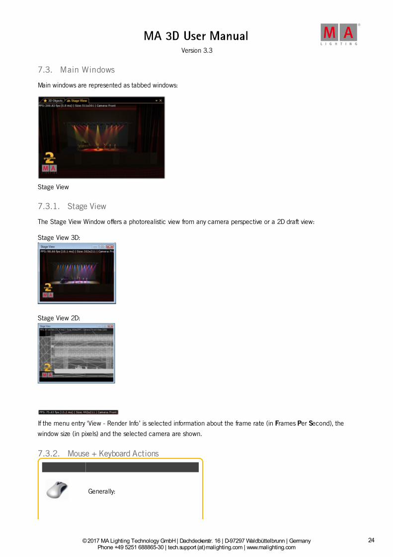
7.3. Main Windows
Main windows are represented as tabbed windows:
Stage View
7.3.1. Stage View
The Stage View Window offers a photorealistic view from any camera perspective or a 2D draft view:
Stage View 3D:
Stage View 2D:
If the menu entry 'View - Render Info’ is selected information about the frame rate (in Frames Per Second), the
window size (in pixels) and the selected camera are shown.
7.3.2. Mouse + Keyboard Actions
Generally:
24

© 2017 MA Lighting Technology GmbH | Dachdeckerstr. 16 | D-97297 Waldbüttelbrunn | GermanyPhone +49 5251 688865-30 | tech.support (at)malighting.com | www.malighting.com
Version 3.3
1
+ left mouse button actions for objects,
right mouse button actions for camera
Left Mouse Button: Moving and Rotating of Objects
WorldaxisCtrl +W
ObjectAxisCtrl +O
Objects can be moved or rotatedalong the world-or their own axis.Hold the left mouse button down
to change between Move and
Rotate and vice versa.
- Select the object
- Move or rotate it along theselected axis
LeftmousebuttondowntomoveobjectalongworldorobjectaxisLeftmousebuttondowntorotateobjectaroundworldorobjectaxis
Right Mouse Button:Context Menu +Camera Actions
25

© 2017 MA Lighting Technology GmbH | Dachdeckerstr. 16 | D-97297 Waldbüttelbrunn | GermanyPhone +49 5251 688865-30 | tech.support (at)malighting.com | www.malighting.com
Version 3.3
1
Short right mouse click Menu for
selecting, renaming deleting duplicatingor grouping selected object
Right mouse button down Select action
with scroll wheel or 'Shift + Ctrl’
Middle Mouse Button: Select Camera or Zoom
Mouse wheel click after that Set camera for this view via the mouse wheel turn or keyboard
space or 1…9..0 button
Mouse wheel turn Zoom in or out
7.3.3. Arrangement of Objects (Align Objects)
26

© 2017 MA Lighting Technology GmbH | Dachdeckerstr. 16 | D-97297 Waldbüttelbrunn | GermanyPhone +49 5251 688865-30 | tech.support (at)malighting.com | www.malighting.com
Version 3.3
1
7.3.3. Arrangement of Objects (Align Objects)
MA 3D allows automatic arrangement of 3D objects. Therefore select the objects to arrange via 'Ctrl + mouse click’or multiple selections in the assets tree. Via the menu entry 'Functions - Arrangement’ the Arrangement Windowopens:
Objects can be arranged in several ways like:- Moved along the X,Y,Z axis-Moved along a circle line in X,Y,Z space- Arrange in a 2D matrix Correspondingto the grandMA2 console alignment function objects can be arranged inrelation to the origin object like:- <, >, ><, and <>If the 'Relative’ flag is setevery push of the 'Apply’ button increments the arrangement by the givenvalue. Note: The origin is 0,0,0 if the 'Relative’ flag is off. Otherwise it is the ownposition.
Example: Several objects inserted into the Stage View at the origin (0,0,0).
Objects aligned via 'Move’ and 'Align <’ function along the X-axis.
Objects aligned as a matrix via 'Matrix (2D)’ function.
7.3.4. Duplicate (copy 3D Objects)
27

© 2017 MA Lighting Technology GmbH | Dachdeckerstr. 16 | D-97297 Waldbüttelbrunn | GermanyPhone +49 5251 688865-30 | tech.support (at)malighting.com | www.malighting.com
Version 3.3
1
7.3.4. Duplicate (copy 3D Objects)
You can duplicate objects via a mechanism in a comfortably way. Therefore do a multi selection in any view via leftmouse button + 'Ctrl or Shift’ and select the menu entry 'Functions - Duplicate’. The Duplicate window appears:
You can set the number of desired copies. If the objects contain sub-objects select if these are copied too.
Information:It is not possible to create new fixtures within MA 3D!
If fixtures are selected to duplicate it is possible to select 'Use other Fixtures’. Select the 'First Destination Fixture’inside the list box. After pressing the 'Duplicate’ button the 'First Destination Fixture’ will be moved to the X,Y,Zposition of the source fixture and so on. This mechanism is useful to create symmetrical stage sets. For example youhave to setup the number of all used fixtures inside the set. Do the setup for the left side of trusses and lanterns.After that you can duplicate the left side and mirror it to the right side.
7.3.5. 3D Objects
28

© 2017 MA Lighting Technology GmbH | Dachdeckerstr. 16 | D-97297 Waldbüttelbrunn | GermanyPhone +49 5251 688865-30 | tech.support (at)malighting.com | www.malighting.com
Version 3.3
1
7.3.5. 3D Objects
This view offers information about all used objects in a grid view. All used 3D objects and fixtures are listed in thisgrid. Single or multiple objects can be selected for manipulation or duplicating. The objects can be sorted by a leftmouse click into the headline of a column.
The symbols inside the grid have the following meanings:
Name Meaning
3D object
Fixture object
Grouping object
Property Meaning
Object is visible or hidden in Stage View
Sunshade is on or off
Followspot is active or inactive on object surface
7.4. Assets (Information Window)
29

© 2017 MA Lighting Technology GmbH | Dachdeckerstr. 16 | D-97297 Waldbüttelbrunn | GermanyPhone +49 5251 688865-30 | tech.support (at)malighting.com | www.malighting.com
Version 3.3
1
The default window layout gives you the assets window and the properties window at the right screen border.
It is useful to have them both visible together.
If you click on an element in the assets window, the properties window gives you the properties to the selectedelement.
The assets window is a tree structure view including
Cameras
3D Objects
Videos
grandMA2
Media Database
In the assets window you can
select objects
add groups
group objects
select children
delete objects
30

© 2017 MA Lighting Technology GmbH | Dachdeckerstr. 16 | D-97297 Waldbüttelbrunn | GermanyPhone +49 5251 688865-30 | tech.support (at)malighting.com | www.malighting.com
Version 3.3
1
Titlebar Icon Description
Adds a new group folder in the tree structure of the 3D Objects.
Creates a new group of the selected 3D Objects.
Selects the children of a group.
Deletes selected objects in the tree
The icons next to the cameras or the 3D objects displays the status. Click on the icon to change the status.
CameraIcon
Description
You can step viakeyboard (space button)to the next camera. Notselected cameras areignored.
3DObjectIcon
Description
Followfunction ofthe 3Dobjectsurface ison / off.
3D objectisselectableor not inthe stageview.
3D objectis visible /invisible inthe stageview.
Consolepropertieslike MA Netsettings,Followspot fromconsole,Units(changeunits frommeter toinch etc.)
Hint:If you want to change the unit e.g. from meters to feet open the grandMA2 tree in the assets window,select 'Units' and switch the unit to 'feet'.
31

© 2017 MA Lighting Technology GmbH | Dachdeckerstr. 16 | D-97297 Waldbüttelbrunn | GermanyPhone +49 5251 688865-30 | tech.support (at)malighting.com | www.malighting.com
Version 3.3
1
7.5. Properties
The Property window informs about the properties of the actual selectedobject like fixtures or 3D objects. If several objects are selected e.g. via 'Ctrl+ mouse’ only the fields with equal information are filled, other fields arecross striped. You can change the settings of one or all selected objectshere.
Numerical values can be in- or decremented via the mouse wheel (+Ctrl or+Shift) if the field is selected. Units can be changed in the Assets tree at'Ma Net’ see above. Also the sizes can be changed absolute or as scalingfactor. This can be done via the menu entry 'View - Units’
Hint:If you want to change the unit e.g. from meters to feet open the grandMA2 tree in the assets window,select 'Units' and switch the unit to 'feet'
7.6. Media Database
32

© 2017 MA Lighting Technology GmbH | Dachdeckerstr. 16 | D-97297 Waldbüttelbrunn | GermanyPhone +49 5251 688865-30 | tech.support (at)malighting.com | www.malighting.com
Version 3.3
1
7.6. Media Database
To open the media database, click on View in the menu bar and then Media Database. Import 3D objects from the
media database into the stage view.
The media database provides 3D objects for the stage. There are 12 different folders available.
On the top is a filter field. Type the search word in the filter to search a specific object in the media database.
There are two views available. The icon view and the grid view.
The icon view displays an icon of the 3D object along with the name.
To import a 3D object from icons view into the stage view, select the object and move it via drag and drop into thestage view or double click on the icon.
The grid view displays additional in columns the
category
device class
author of the 3D object
model key
size of the object in metric (length, width, height)
vertices
size of the 3D object in bytes
To import a 3D object from the grid view into the stage view, double click on the object row.
7.7. Materials
33

© 2017 MA Lighting Technology GmbH | Dachdeckerstr. 16 | D-97297 Waldbüttelbrunn | GermanyPhone +49 5251 688865-30 | tech.support (at)malighting.com | www.malighting.com
Version 3.3
1
7.7. Materials
If an object is selected the Materials window shows all used materials (texture images) of the object. Select thematerial in the Material window and you can change its properties (diffuse color, emissive color, specular power,texture) in the property window. The results can be viewed directly in the Stage View window.
7.8. Video Player
You can cover surfaces of 3D Objects not only with textures but also with videos. These video files can be controlledby the Video Player
The local video can be looped or run once. The video file is handled by the Material Data base. If the video type isCITP the Frame Rate can be selected via the shown slider. If you want to load a new video file open the Materialswindow and select the texture field...
Here you can browse to the video file location.
34

© 2017 MA Lighting Technology GmbH | Dachdeckerstr. 16 | D-97297 Waldbüttelbrunn | GermanyPhone +49 5251 688865-30 | tech.support (at)malighting.com | www.malighting.com
Version 3.3
1
Information:The following file formats for videos located local disc are supported: Video(*.drc, *.mkv, *.ogg, *.ogv,*.webm, *.wmv)
If CITP is enabled in the Network Configuration of the grandMA2 or onPC you can select the video source in the CITPstream. Select the Mediaserver and the source:
7.9. Moving Paths
35

© 2017 MA Lighting Technology GmbH | Dachdeckerstr. 16 | D-97297 Waldbüttelbrunn | GermanyPhone +49 5251 688865-30 | tech.support (at)malighting.com | www.malighting.com
Version 3.3
1
7.9. Moving Paths
Moving Paths allow the movement of objects like trusses with their attached sub objects like fixtures, trusses etc..
Moving Paths are managed like fixture types in the desk. To setup a Moving Path, create a new fixture in the deskfrom the library. Choose the Manufacturer 'MA Lighting’ and the type 'Moving Path…’. There are several types ofMoving Paths. The type (Rotate, Scale…) specifies the parameters controlled by the desk:
The object rotates once around the axes of the Moving Path.
The object is scaled in X,Y and Z dimensions.
The object rotates continuously around the axes of the Moving Path. The rotation speed can be setin rotations per minute at the desk.
The object can be moved in X, Y and Z direction.
Combined Moving Path of Translation, Rotation and Scale. This type is more easy to use instead ofconcatenating the single types.
Controlling of the position is always done relative to the origin coordinates. I.e. if an object with moving paths is
moved manually, the tracks of the Moving Paths are always moved parallel to the new object coordinates.
You can attach an object to a Moving Path viadragging the object in the tree.Drop it onto the desired Moving Path.The pictured example shows a truss with 4 movinghead fixtures (1000A 1…4) mounted on a truss (FS34-400 1…2).
The example shows a 'Translation’ Moving Pathcontrolled in Z-direction.The truss moves up and down controlled by the desk.
36

© 2017 MA Lighting Technology GmbH | Dachdeckerstr. 16 | D-97297 Waldbüttelbrunn | GermanyPhone +49 5251 688865-30 | tech.support (at)malighting.com | www.malighting.com
Version 3.3
1
7.10. Sessions
The Session window gives an overview about all running sessions in MA net. Name, ID and the state of the sessionsare displayed. The streaming version is important for the compatibility.
Sessions can be created from grandMA2 console/onPC only, refer to MA Network Configuration - 3D.
To suppress the automatic inviting to a session press the 'Invite Enabled' button. Then the inviting will be disabled.
7.11. Status Bar
The status bar is at the bottom border of the program window.
The status bar includes the following elements:
Network Type: Displays the network type.
Connection State: The connection state displays, which connection the MA 3D has, along with the name of thesession. To open the Sessions Window, click on the connection state.
MA 3D has no connection to a session.
MA 3D has joined a session as a slave.
Show: Displays the name of the show file.
User: Displays which user is logged in. Click on user, to change the user. The login pop-up opens.
World: Displays the world. Click on the world, to open the select world window.
CITP State: Displays the CITP state. Enable or disable the CITP from in the CITP Network Configuration of thegrandMA2 or onPC.
CITP is disabled.
CITP is enabled.
Item Selected: Displays how many items are currently selected.
37

© 2017 MA Lighting Technology GmbH | Dachdeckerstr. 16 | D-97297 Waldbüttelbrunn | GermanyPhone +49 5251 688865-30 | tech.support (at)malighting.com | www.malighting.com
Version 3.3
1
7.12. Windows Layout
For a better overview, you can arrange your window layout.
If you have a small screen, it could be better to fade out additional views.
To fade out views, click on the little x. If you want to have the view later, got it in the menu bar.
Another option is to pin views on the screen border. Pined views creates view tabs on the right or bottom screenborder. If you move the mouse over the tabs, the view appears.
To pin views, click on the pin needle. To deactivate the pin function, click on the pin needle again.
38

© 2017 MA Lighting Technology GmbH | Dachdeckerstr. 16 | D-97297 Waldbüttelbrunn | GermanyPhone +49 5251 688865-30 | tech.support (at)malighting.com | www.malighting.com
Version 3.3
1
Another option is to move views on a different area. You can move and dock views on the left-, right-, upper-, andlower screen border.
To move a view, click and hold the title bar of a view, move it to an arrow and release the mouse button.
Another option is to undock views and open them in an own window.
To undock views, click and hold the title bar of a view, and move them out of the main screen. The view opens inan own window.
Save/Load/Reset/Delete Window Layout
You can save the arranged window layout and load it.
Window Layouts will be saved in "C:\Users\xxx\AppData\Roaming\MA LightingTechnologies\ma3d\3.0.0\WindowLayouts".
You will find all actions and commands regarding the window layout in the menu bar "View - Window Layout".
Save Window Layout
Save a window layout via "View - Window Layout - Save Window Layout".
Load Window Layout
To load a previous saved window layout, open "View - Window Layout - Load Window Layout".
Choose the window layout. If there is no window layout available, you did not saved one.
If you cannot find your window layout, use the search function from the windows explorer and search for the end of
the file name ".gma3dwindow".
Reset Window Layout
Reset the window layout via "View - Window Layout - Reset Window Layout".
You get the default window layout back.
39

© 2017 MA Lighting Technology GmbH | Dachdeckerstr. 16 | D-97297 Waldbüttelbrunn | GermanyPhone +49 5251 688865-30 | tech.support (at)malighting.com | www.malighting.com
Version 3.3
1
Delete Window Layout
To delete a window layout there is no function in the menu bar. Use the windows explorer or go to "View - Window
Layout - Load Window Layout", click on the window layout, right mouse button and delete.
40

© 2017 MA Lighting Technology GmbH | Dachdeckerstr. 16 | D-97297 Waldbüttelbrunn | GermanyPhone +49 5251 688865-30 | tech.support (at)malighting.com | www.malighting.com
Version 3.3
1
8. Fixture Types
The following table gives an overview about the visualization effects in MA 3D.
Information:Unlike other effects all of these axes must be included in the basing 3d-model. This is a prerequisite forfixtures and moving paths. If the model has no axis nothing will move.
Effect in MA3D
DescriptionPresetType
Feature Attribute SubattributeUnit ofMeasurement
Axis (axis offixtures ormovingpaths)
PanPan-axis offixtures
POSITION POSITION PAN PANAngle indegrees
TiltTilt-axis offixtures
POSITION POSITION TILT TILTAngle indegrees
RollRoll-axis offixtures
POSITION POSITION ROLL ROLLAngle indegrees
Translation X,Translation Y,Translation Z,
Translation inx-, y- or z-direction, e.g.for movingpaths
POSITIONMP_TR (MPTrans)
MP_TR_X (X),MP_TR_Y (Y),MP_TR_Z (Z)
MP_TR_X (X), MP_TR_Y (Y),MP_TR_Z (Z)
Translationrange inmeter
Scaling X,Scaling Y,Scaling Z
Scaling ofobjects in x-, y-or z-direction,e.g. for movingpaths
POSITIONMP_SC (MPScale)
MP_SC_X (X),MP_SC_Y (Y),MP_SC_Z (Z)
MP_SC_X (X), MP_SC_Y (Y),MP_SC_Z (Z)
Scaling factor(must be >0!)
Rotation X,Rotation Y,Rotation Z
Rotationaround x-, y- orz-axis, e.g. formoving paths
POSITIONMP_ROT (MPRot)
MP_ROT_X (X),MP_ROT_Y (Y),MP_ROT_Z (Z)
MP_ROT_X (X), MP_ROT_Y (Y),MP_ROT_Z (Z)
Angle indegrees
Spin X, SpinY, Spin Z
Continuousrotation aroundx-, y- or z-axis
POSITIONMP_SPIN(MP Spin)
MP_SPIN_X (X),MP_SPIN_Y (Y),MP_SPIN_Z (Z)
MP_SPIN_X (X), MP_SPIN_Y_ (Y),MP_SPIN (Z)
Rotationspeed inrotations perminute (rpm)
ClampPitch of theclamp
POSITIONMP_ROT (MPRot)
CLAMP CLAMPAngle indegrees
41

© 2017 MA Lighting Technology GmbH | Dachdeckerstr. 16 | D-97297 Waldbüttelbrunn | GermanyPhone +49 5251 688865-30 | tech.support (at)malighting.com | www.malighting.com
Version 3.3
1
Barndoor 1,Barndoor 2,Barndoor 3,Barndoor 4
Pitch ofbarndoors infront of the lens
SHAPERS BARNDOORS
BARNDOORS 1(Bd1),BARNDOORS 2(Bd2),BARNDOORS 3(Bd3),BARNDOORS 4(Bd4)
BARNDOORS 1 (Bd1),BARNDOORS 2 (Bd2),BARNDOORS 3 (Bd3),BARNDOORS 4 (Bd4)
Angle rangein degrees; 0°= barndoor isin sameposition like inmodel> 0° =closebarndoor
Effect in MA3D
DescriptionPresetType
Feature Attribute SubattributeUnit ofMeasurement
Light Output
Shutter BEAM SHUTTER SHUTTER SHUTTER0 = shutterclosed, 1 =shutter open
Strobe/StrobeFrequency
Strobe effectswith randomand softopening/closingoption
BEAM SHUTTER SHUTTER
STROBE, STROBE_PULSE (Pulse),STROBE_PULSE_CLOSE (PulseClose), STROBE_PULSE_OPEN(Pulse open), STROBE_RANDOM(Rnd), STROBE_RANDOM_PULSE(Rnd Pulse),STROBE_RANDOM_PULSE_CLOSE(Rnd Pulse Close),STROBE_RANDOM_PULSE_OPEN(Rnd Pulse Open)
Strobefrequency inHz (biggerthan 0)
Strobe Ratio BEAM SHUTTER STROBE_RATIO STROBE_RATIO (Duty Cycle)
Slice of 1.0.5means thatthe shutter isopen half thestrobeinterval.
DimmerIntensity of lightsource
DIMMER DIMMER DIM DIM, DIM 2, DIM 3
Factor on thefixture typeintensity 0.0 =off 1.0 =maximum
Effect in MA3D
DescriptionPresetType
Feature Attribute SubattributeUnit ofMeasurement
Light Effects
ColorColor of beamor led surfaces
COLOR
COLOR 1,COLOR 2,COLOR 3,COLOR 4
COLOR 1,COLOR 2,COLOR 3,COLOR 4
COLOR 1 (Select), COLOR 2(Select 2), COLOR 3 (Select 3),COLOR 4 (Select 4)
Color
ScrollerColor of abeam
COLORCOLORALL(Color)
SCROLLER SCROLLERSELECT (Scroller) Color
42

© 2017 MA Lighting Technology GmbH | Dachdeckerstr. 16 | D-97297 Waldbüttelbrunn | GermanyPhone +49 5251 688865-30 | tech.support (at)malighting.com | www.malighting.com
Version 3.3
1
Zoom FOCUS FOCUS ZOOM ZOOMAngle indegrees
Iris BEAM BEAM1 IRIS IRIS
Factor 0.0 =iris completelyclosed, 1.0 =iris open
Prism BEAM BEAM1PRISMA1(Prism1)
PRISMA1 (Prism1)
Prism angle indegrees(anglebetweencenter ofbeam withoutprism andwith prism).Additionalphysicalamount ofbeams.
PrismPosition
Rotation of theprism
BEAM BEAM1PRISMA1_POS(Pos1)
PRISMA1_POS (Pos)Angle indegrees
PrismRotation
Continuousrotation of theprism
BEAM BEAM1PRISMA1_POS(Pos1)
PRISMA1_ROT (Rot)Rotationspeed in rpm
Frost BEAM BEAM1 FROST FROST0.0 = no frost,1.0 =maximum
Effect in MA3D
DescriptionPresetType
Feature Attribute SubattributeUnit ofMeasurement
Gobo (3wheelsmaximum)
Gobo X(WheelPosition)
Selects gobofrom valuesinsidefunctionalblock
GOBOGOBO 1,GOBO 2,GOBO 3
GOBO1 (G1),GOBO2 (G2),GOBO3 (G3)
GOBO 1 (Select), GOBO 2(Select2), GOBO 3 (Select3),GOBO1_SPIN (Spin), GOBO2_SPIN(Spin2), GOBO3_SPIN (Spin)
-
Gobo X -Position
Rotation ofcurrent gobo
GOBOGOBO 1,GOBO 2,GOBO 3
GOBO1_POS (G1<>), GOBO2_POS(G2 <>),GOBO3_POS (G3<>)
GOBO1_POS (Index), GOBO2_POS(Index2), GOBO3_POS (Index3)
Angle indegrees
43

© 2017 MA Lighting Technology GmbH | Dachdeckerstr. 16 | D-97297 Waldbüttelbrunn | GermanyPhone +49 5251 688865-30 | tech.support (at)malighting.com | www.malighting.com
Version 3.3
1
Gobo X -Rotation
Continuousrotation of thecurrent gobo
GOBOGOBO 1,GOBO 2,GOBO 3
GOBO1_POS (G1<>), GOBO2_POS(G2 <>),GOBO3_POS (G3<>)
GOBO1_ROT (Rotate),GOBO2_ROT (Rotate2),GOBO3_ROT (Rotate3)
Rotation inrpm
Effect in MA3D
DescriptionPresetType
Feature Attribute SubattributeUnit ofMeasurement
Blades (4bladesmaximum)
Blade X -Insertion (A)
Insertion of theblade into thebeam. Thisattribute has tobe present tovisualize anyblade.
SHAPERSSHAPER(Frames)
BLADE1A (1A),BLADE2A (2A),BLADE3A (3A),BLADE4A (4A)
BLADE1A (1A), BLADE2A (2A),BLADE3A (3A), BLADE4A (4A)
0.0 = noinsertion, 1.0= full covering
Blade X -Insertion (B)
Secondinsertion rangefor every bladefor rotation. Ifthis option isused, you mustno use the"Blade X -Rotation" -option.
SHAPERSSHAPER(Frames)
BLADE1B (1B),BLADE2B (2B),BLADE3B (3B),BLADE4B (4B)
BLADE1B (1B), BLADE2B (2B),BLADE3B (3B), BLADE4B (4B)
0.0 = noinsertion, 1.0= full covering
Blade X -Rotation
Rotation of theblade. If thisoption is used,you must notuse the "BladeX - Insertion(B)" option.
SHAPERSSHAPER(Frames)
BLADE1ROT(1Rot),BLADE2ROT(2Rot),BLADE3ROT(3Rot),BLADE4ROT(4Rot)
BLADE1ROT (1Rot), BLADE2ROT(2Rot), BLADE3ROT (3Rot),BLADE4ROT (4Rot)
Angle indegrees
Rotation ofall blades
SHAPERSSHAPER(Frames)
SHAPER ROT(FrameAssembly)
SHAPER ROT (Index)Angle indegrees
44
© 2017 MA Lighting Technology GmbH | Dachdeckerstr. 16 | D-97297 Waldbüttelbrunn | GermanyPhone +49 5251 688865-30 | tech.support (at)malighting.com | www.malighting.com
Version 3.3
1
9. 3D Modeling and Import
MA 3D is created for the visualization of three-dimensional stage layouts to be utilized together with lighting controldesks of MA. It comes with a library of common types of light fixtures e.g., par cans, moving mirror, moving headsand LED fixtures.
With this large number of different fixtures, it is not possible to cover all models. MA 3D offers the opportunity toimport 3D models created via a 3D CAD program. Most of the 3D CAD programs offer the export into the .3ds format.
Hint:This tutorial requires the knowledge of handling a 3D construction program.
3D models are created with 3D design programs such as ‘Cinema 4D’, 3Ds Max, etc. After creation, the model isimported in .3ds format via the MA 3D import function. The import tool can be found using the menu entry: ‘File –Import – Import 3D Model…’. Single files as well as complete directories can be imported.
It is possible to apply parameters to objects inside a 3D model. These parameters influence the behavior of theobject within MA 3D.The parameters are defined using the name of the object. They are organized in a hierarchic order.A parameter block begins with '_X'. The sub-parameter follows without separators, e.g., 'Test_XAP' identifies theobject as an axis of the pan movement.For more information see Creation of a 3D Fixture Model and Parameters.
45

© 2017 MA Lighting Technology GmbH | Dachdeckerstr. 16 | D-97297 Waldbüttelbrunn | GermanyPhone +49 5251 688865-30 | tech.support (at)malighting.com | www.malighting.com
Version 3.3
1
Import 3D Model dialog
The imported model can be viewed in the ‘Model Test Area’ window that can be operated similarly to the 3D ‘StageView’.Properties such as ‘Name’, ‘Category’, etc. can also be edited. After the editing, the model can be stored in themedia database and is ready to be used in MA 3D.
9.1. Workflow
Construct the new 3d model using an external 3D CAD tool such as Cinema 4D, 3Ds Max etc.
Hint:This example uses Cinema 4D, but any tool that can export the 3ds format can be used.
This is a short overview on the process of building 3D models and importing them into MA 3D:
Technical Drawing
For the construction a drawing with the dimensions of the fixture is needed.In this example a Vari-Lite VL1000 is used.
46

© 2017 MA Lighting Technology GmbH | Dachdeckerstr. 16 | D-97297 Waldbüttelbrunn | GermanyPhone +49 5251 688865-30 | tech.support (at)malighting.com | www.malighting.com
Version 3.3
1
Vari-Lite VL1000
Creation of the 3D Model
Create a 3D model with a 3D CAD program.Respect the restrictions of the 3D objects and names.
2D wireframe of the Vari-Lite VL1000 model
Hierarchic structure of the 3D model
Export the CAD File into .3ds format.
47

© 2017 MA Lighting Technology GmbH | Dachdeckerstr. 16 | D-97297 Waldbüttelbrunn | GermanyPhone +49 5251 688865-30 | tech.support (at)malighting.com | www.malighting.com
Version 3.3
1
Import into MA 3D
Import the model into MA 3D.The import tool generates a unique model key to identify it later. It saves all properties of the model into an .xmldescription file.
The final 3D model in MA 3D
After saving the model in the media database it is ready to be used in MA 3D. If the model is saved in an existingmedia database file, restart MA 3D. For more information see Import 3D Model to MA 3D.
9.2. 3D Models Principles
48

© 2017 MA Lighting Technology GmbH | Dachdeckerstr. 16 | D-97297 Waldbüttelbrunn | GermanyPhone +49 5251 688865-30 | tech.support (at)malighting.com | www.malighting.com
Version 3.3
1
9.2. 3D Models Principles
The import tool does not subsequently edit the 3D model. The imported 3D model must contain all information.
To avoid determination on a specific modeling tool, choose the '3DS’ file format. This format can be exported bymost applications.
All parameters can be referred to using the names of the simple objects.
Important Restrictions for 3D Objects: Names of objects max. 8 characters (incl. parameters)
No special characters allowed
Names must be unique - each object must have a unique name
Important:Note that some modeling applications shorten names while exporting to 3DS. The name must stayunique after the export.
All objects must consist of triangles(e.g., Cinema 4D 'Functions - Make Editable’ & 'Functions - Triangulate’)
Only one material can be assigned to an object
Only one texture can be assigned to a material
Follow these limitations even if you could use other file formats in the future. Furthermore, 3D objects should consistof as few triangles as possible. Curves can be pictured realistically using small triangles if the normal simulates this(Cinema 4D: 'Phong Tag’).
Important:The max. angle for curves is set to 89.5° in Cinema 4D (in 3DS).
9.3. Creation of a 3D Model
3D objects can be created with 3D CAD programs. The amount of polygons affects the performance because foreach polygon the projection has to be calculated. The lesser the number of polygons, the better the frame rate.
MA 3D supports the following formats for 3D objects:
• .3ds - Format for drawing 3 dimensional objects
Important:
The orientation of the object has to fit
Normals have to be organized correctly
UV coordinates for the textures have to be setup correctly
49

© 2017 MA Lighting Technology GmbH | Dachdeckerstr. 16 | D-97297 Waldbüttelbrunn | GermanyPhone +49 5251 688865-30 | tech.support (at)malighting.com | www.malighting.com
Version 3.3
1
This example shows the creation of a halved cylinder created with Cinema 4D:
Insert an object of type 'Cylinder’.
Set the orientation to "+Y".
Comparison of axes in MA 3D and Cinema 4DMA 3D Cinema 4D
X XY ZZ Y
For the correct orientation of the object in MA 3D, it is important to set thecorrect orientation in Cinema 4D.
Make the object editable.
Select polygons that are not used.
50

© 2017 MA Lighting Technology GmbH | Dachdeckerstr. 16 | D-97297 Waldbüttelbrunn | GermanyPhone +49 5251 688865-30 | tech.support (at)malighting.com | www.malighting.com
Version 3.3
1
Delete them.
Set the option "Tinted Poly Normals" to On in the "View Settings".
The next copy steps are only necessary if the object has to be visible fromboth sides. The object has to be duplicated and the normals have to beset in both directions. First copy the object.
Then reverse the normals of the copy.
Select both cylinder objects and connect them to a new cylinder.
The old cylinder objects can be deleted.
51

© 2017 MA Lighting Technology GmbH | Dachdeckerstr. 16 | D-97297 Waldbüttelbrunn | GermanyPhone +49 5251 688865-30 | tech.support (at)malighting.com | www.malighting.com
Version 3.3
1
Now you can see two objects with normals in both directions.
Check the orientation of the resulting object.
Insert a new material for the texturing.
Assign an image to the texture and the material to the object (Mind therestriction of max. 8 characters + extension for the image name!).
52

© 2017 MA Lighting Technology GmbH | Dachdeckerstr. 16 | D-97297 Waldbüttelbrunn | GermanyPhone +49 5251 688865-30 | tech.support (at)malighting.com | www.malighting.com
Version 3.3
1
Adjust the texture mapping parameter.
Assign the UV coordinates for the texture mapping.
Export the object to 3D Studio format (.3ds). Objects created in this waycan be added via the import tool.
The result.
9.4. Creation of a 3D Fixture Model
53

© 2017 MA Lighting Technology GmbH | Dachdeckerstr. 16 | D-97297 Waldbüttelbrunn | GermanyPhone +49 5251 688865-30 | tech.support (at)malighting.com | www.malighting.com
Version 3.3
1
This example describes the construction of a Head Mover fixture on the example of a Vari-Lite VL-1000.
Note:Whenever creating a new object triangulate it. If you do not triangulate the object, the MA3D import toolignores the object.You can triangulate an object in Cinema 4D in Functions → Make Editable and then Functions →Triangulate.
Cube before (left) and after (right) triangulation
Create the Basement of the 3D Model
3D and 2D (from the right) view of the model
54

© 2017 MA Lighting Technology GmbH | Dachdeckerstr. 16 | D-97297 Waldbüttelbrunn | GermanyPhone +49 5251 688865-30 | tech.support (at)malighting.com | www.malighting.com
Version 3.3
1
2D (top and front) views of the model
Dimensions
The size of the model can be rescaled using the import tool of MA 3D.It is possible to use other scaling factors while creating the model.In this case a scaling of 100 is used (1m = 1cm).The xml description file then contains the following line:
<Scale>0.01</Scale>
Coordinate settings of a model in Cinema 4D
The housing of the basement is the root of the object tree and uses the name of the model name 'VL1000'. Itconsists of a low number of polygons joined to a flattened box. To reduce the number of polygons, use the pointcollapse plugin in Cinema 4D.
Hierarchic structure in Cinema 4D after creating the basement
Colors and Textures
Colors and textures are defined by the material. Add the UVW tag for texture mapping and a material by draggingthe material to the object.
Hint:MA 3D uses the assigned texture. Therefore, the texture file (max. 8 characters) must be placed in thesame folder as the .3ds file.
55

© 2017 MA Lighting Technology GmbH | Dachdeckerstr. 16 | D-97297 Waldbüttelbrunn | GermanyPhone +49 5251 688865-30 | tech.support (at)malighting.com | www.malighting.com
Version 3.3
1
Color setting of a material in Cinema 4D
Normals
Mark the visibility of the areas. In Cinema 4D they are marked with white lines.
Hint:To make both sides visible, duplicate the object and reverse the normals of the duplicate.
Marked visibility of the basement in Cinema 4D
Anchor for the Pan Axis [_XAP]
To provide the pan movement in MA 3D, the name of the object has to begin with an _X.
The _X marks a parameter block. All child objects follow the pan movement.
The following sub parameters AP marks the axis A and defines the pan movement P. The name of the pan anchor is
_XAP.
The material is transparent.
Hierarchic structure with the added pan axis
Transparent material of the pan axis
56

© 2017 MA Lighting Technology GmbH | Dachdeckerstr. 16 | D-97297 Waldbüttelbrunn | GermanyPhone +49 5251 688865-30 | tech.support (at)malighting.com | www.malighting.com
Version 3.3
1
Yoke for the Pan Axis [U_XSX]
The yoke is a child object of the anchor of the pan axis.It has the same UVW tag and material as the basement.
Hierarchic structure after adding the yoke
3D model in Cinema 4D with basement, pan axis and yoke
Anchor for the Tilt Axis [_XAT]
To provide the tilt movement, the object is named _XAT. All child objects follow the tilt movement.
The material is transparent.
Hierarchic structure with the newly added tilt axis
57

© 2017 MA Lighting Technology GmbH | Dachdeckerstr. 16 | D-97297 Waldbüttelbrunn | GermanyPhone +49 5251 688865-30 | tech.support (at)malighting.com | www.malighting.com
Version 3.3
1
Current progress of the 3D model with the invisible material of the tilt axis
Lamp Head [H_XSX]
The lamp head is a child object of the anchor of the tilt axis.The name is H_XSX this means:
H - is ignored
_X - Parameter
SX - Sunshade type excludes the own beam
It has the same UVW tag and material as the basement.
Hierarchic structure with the lamp head
3D model with the lamp head
Lens [L_XSN]
The lens is a child object of the lamp head.The name is L_XSN this means:
L - is ignored
_X - Parameter
SN - Sunshade type is None. Neither is the beam affected nor are the gobos projected on the object.
It has the same UVW tag and material as the basement housing.
58

© 2017 MA Lighting Technology GmbH | Dachdeckerstr. 16 | D-97297 Waldbüttelbrunn | GermanyPhone +49 5251 688865-30 | tech.support (at)malighting.com | www.malighting.com
Version 3.3
1
Hierarchic structure after adding the lens
2D view with the lens
Origin of the Beam [_XB]
The origin of the beam is a child object of the lamp head.The name is ‘_XB’ this means:_X - Parameter
B - Origin of the Beam cone
The material is transparent.
Final hierarchic structure after adding the beam
59

© 2017 MA Lighting Technology GmbH | Dachdeckerstr. 16 | D-97297 Waldbüttelbrunn | GermanyPhone +49 5251 688865-30 | tech.support (at)malighting.com | www.malighting.com
Version 3.3
1
Beam object in 2D view
After you have created the model, export it into 3D Studio format (.3ds).
9.5. Import 3D Model to MA3D
Import 3D Models into MA 3D
Open MA 3D
Media Database
In the Media Database (View - Media Database Window) you can find all 3D objects ordered in a hierarchicalstructure. Types of fixtures are located in the corresponding folder. All fixtures of the type Head Mover are located inthe folder "Head Mover".
Open the Import Tool
1. Open the import tool the menu entry ‘File – Import – Import 3D Model’.2. Select ‘Import 3D Model’.3. Select the 3D file ‘Vari-Lite_VL1000.3ds’ you have created.
The Import 3D Models tool
Entering 3D Model Properties
When import is done an .xml description file is generated and stored in the folder parallel to the .3ds file. Forexample ‘Vari-Lite_VL1000.import.xml’.
60
© 2017 MA Lighting Technology GmbH | Dachdeckerstr. 16 | D-97297 Waldbüttelbrunn | GermanyPhone +49 5251 688865-30 | tech.support (at)malighting.com | www.malighting.com
Version 3.3
1
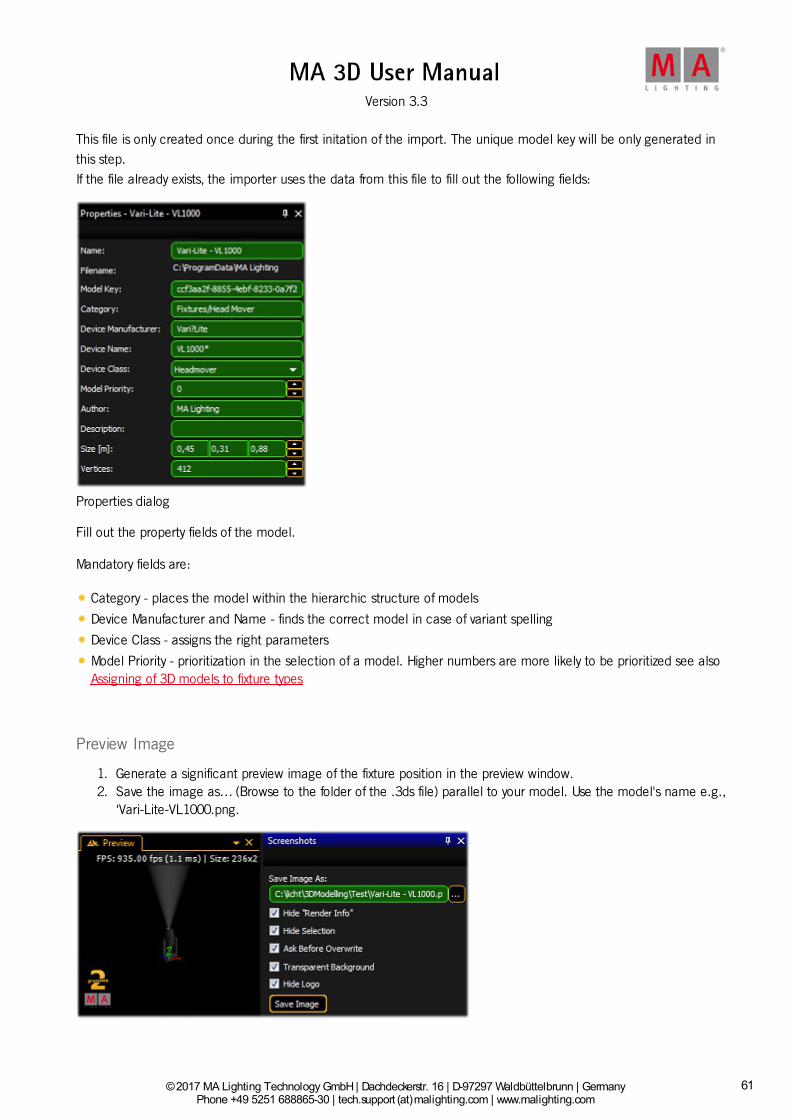
This file is only created once during the first initation of the import. The unique model key will be only generated inthis step.If the file already exists, the importer uses the data from this file to fill out the following fields:
Properties dialog
Fill out the property fields of the model.
Mandatory fields are:
Category - places the model within the hierarchic structure of models
Device Manufacturer and Name - finds the correct model in case of variant spelling
Device Class - assigns the right parameters
Model Priority - prioritization in the selection of a model. Higher numbers are more likely to be prioritized see alsoAssigning of 3D models to fixture types
Preview Image
1. Generate a significant preview image of the fixture position in the preview window.2. Save the image as… (Browse to the folder of the .3ds file) parallel to your model. Use the model's name e.g.,
‘Vari-Lite-VL1000.png.
61

© 2017 MA Lighting Technology GmbH | Dachdeckerstr. 16 | D-97297 Waldbüttelbrunn | GermanyPhone +49 5251 688865-30 | tech.support (at)malighting.com | www.malighting.com
Version 3.3
1
Save the 3D Model
To save the 3D model as grandMA Media file, use the save function ‘File’ - ‘Save’ e.g., ‘test.gmamedia’.
Media databse with the created 3D model
The fixture is now saved in the media database in the category Fixtures/Head Mover. The image is displayed as athumbnail.
9.6. Assigning of Models to Fixture Types
62

© 2017 MA Lighting Technology GmbH | Dachdeckerstr. 16 | D-97297 Waldbüttelbrunn | GermanyPhone +49 5251 688865-30 | tech.support (at)malighting.com | www.malighting.com
Version 3.3
1
9.6. Assigning of Models to Fixture Types
Field Description
ModelKey
Unique key of the model. This key is created with the first importing of the modeland saved in the XML file (*.ImportSettings.xml). The key identifies exactly themodel. If the model is imported again the same key will be used from the XMLfile.
DeviceManufacturer Manufacturer of the fixture that is represented by the model.
DeviceName Name of the fixture that is represented by the model.
DeviceClass Type of the model if it represents a fixture. E.g. 'Headmover’
ModelPriority Priority for selecting this model. High numbers are more probable. The standardvalue '0’ should only be used if the meaning is clear, see description below.
At best the fixture type of a device is left in the data base. If the very same type is found by MA 3D (ModelKey ==Model.ModelKey) it will be used without any validation. In this case a fixture type always will be assigned to the samemodel.
If no model key is found the application searches for a more suitable model, like same 'DeviceManufacturer’ ,'DeviceName’ etc..
Hint:The fields 'DeviceManufacturer’ and 'DeviceName’ can be placeholders to find the right model for variantspellings. For example: 'Vari*Lite' is often spelled as ‚Vari-Lite', or a ‚VL1000 AS’ should use the samemodel as 'VL1000 AI’. In this case both fields should contain a ‚Vari?Lite’ and 'VL1000*’.
Possible placeholders:
* 0-n any characters + 1-n any characters ? 0-1 any characters # 1 arbitrary character
Often there are several variants of fixture types in a model range. So the attachment of a '*’ is recommended - forexample: 'VL1000*’. The spelling is not case sensitive.
If a special 3D object shall be used for a model even though a model with the notation exists the 'ModelPriority’ canbe increased (in steps of 100). For example a 'VL1000AS’ with the priority of 100 would be preferred instead of'VL1000*’ with a standard priority of 0.
MA 3D is delivered with standard models for every 'DeviceClass’ type. The standard model has the following setting:DeviceManufacturer = ’*’, DeviceName = '*’ and ModelPriority = -100000. These models have a low priority and areused only if no other model with higher priority is found.
9.7. Checklist for 3D Modeling
63

© 2017 MA Lighting Technology GmbH | Dachdeckerstr. 16 | D-97297 Waldbüttelbrunn | GermanyPhone +49 5251 688865-30 | tech.support (at)malighting.com | www.malighting.com
Version 3.3
1
9.7. Checklist for 3D Modeling
Go through this checklist if you created a 3D model:
Are the settings of the sunshade type in all objects correct?For example, were the calculations of shadow excluded in your own source of light of the fixture body, clamp andhead?
Do the names of objects have more than 8 characters (max. 8 characters)?
Are the names of objects unique?
Are objects made up of triangles only?
Has information got lost during export? To check if the information got lost, open the exported file using themodeling tool.
9.8. Automated Import
Meta data of a 3D model can be left appropriately for the import. Later editing with the import tool is not required.
The placeholder [file] stands for the filename (without extension) that has to be imported. For example if the file'test.3ds’ has to be imported, '[file] stands for 'test':
File Description_global.import.xml Global import setting valid for the complete directory. Structure like [file].import.xml.
[file].import.xmlXML file with meta data for the model. If this file does not exist, it will be createdautomatically to store the model key.
[file].import.png
Preview image of the model. Size is 32x32 pixel (32 Bit RGBA).Will be created if it does not exist.Note: If you use “%o.png” instead of the file name the .png file is generated with the rightname.
[file].png[file].tif[file].bmp[file].jpg
If no preview image exists, the import tool tries to create it.It searches in the given order on the side.The image should be exempted via alpha channel.Borders are cut automatically when the thumbnails are created.
Example for an '*.import.xml’ file:
<?xml version="1.0"?> <GrandMA3DImportSettings xmlns:xsi="http://www.w3.org/2001/XMLSchema-instance" xmlns:xsd="http://www.w3.org/2001/XMLSchema" xmlns="http://schemas.malighting.de/GrandMA3D/GrandMA3DImportSettings/1.0"> <Name>Generic - Head Mover</Name> <Category>Fixtures/Head Mover</Category> <ModelKey>cc6464b5-c992-4b9e-8a96-31691d9cdd90</ModelKey> <DeviceManufacturer>*</DeviceManufacturer> <DeviceName>*</DeviceName> <DeviceClass>Headmover</DeviceClass> <ModelPriority>-100000</ModelPriority> <ModelManufacturer>MA Lighting</ModelManufacturer> <Description>Default Head Mover Model</Description>
64

© 2017 MA Lighting Technology GmbH | Dachdeckerstr. 16 | D-97297 Waldbüttelbrunn | GermanyPhone +49 5251 688865-30 | tech.support (at)malighting.com | www.malighting.com
Version 3.3
1
<Scale>0.01</Scale> <Move>MoveBottomToZ0</Move> <AmbientFlare>0.02</AmbientFlare> </GrandMA3DImportSettings>
Hint:This file is created once the import is initiated.If the file already exists, the importer uses the data from this file to fill out the fields like<Category>Fixtures/Head Mover</Category>.So, these entries need not to be done twice if the model is corrected and imported again.
Overview of possible fields
65
© 2017 MA Lighting Technology GmbH | Dachdeckerstr. 16 | D-97297 Waldbüttelbrunn | GermanyPhone +49 5251 688865-30 | tech.support (at)malighting.com | www.malighting.com
Version 3.3
1
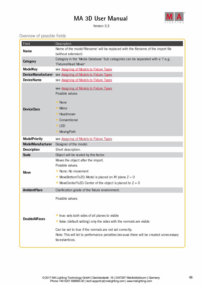
Overview of possible fields
Field Description
NameName of the model'/filename' will be replaced with the filename of the import file(without extension)
CategoryCategory in the 'Media Database’ Sub categories can be separated with a '/’.e.g.'Fixtures/Head Mover’
ModelKey see Assigning of Models to Fixture Types
DeviceManufacturer see Assigning of Models to Fixture Types
DeviceName see Assigning of Models to Fixture Types
DeviceClass
see Assigning of Models to Fixture TypesPossible values:
None
Mirror
Headmover
Conventional
LED
MovingPath
ModelPriority see Assigning of Models to Fixture Types
ModelManufacturer Designer of the model.
Description Short description.
Scale Object will be scaled by this factor.
Move
Moves the object after the import.Possible values:
None: No movement
MoveBottomToZ0: Model is placed on XY plane Z = 0
MoveCenterToZ0: Center of the object is placed to Z = 0
AmbientFlare Clarification grade of the fixture environment.
DoubleAllFaces
Possible values:
true: sets both sides of all planes to visible
false: (default setting) only the sides with the normals are visible
Can be set to true if the normals are not set correctly.Note: This will let to performance penalties because there will be created unnecessaryfaces/vertices.
66

© 2017 MA Lighting Technology GmbH | Dachdeckerstr. 16 | D-97297 Waldbüttelbrunn | GermanyPhone +49 5251 688865-30 | tech.support (at)malighting.com | www.malighting.com
Version 3.3
1
Hint:Fields that are not used can be omitted.
9.9. Parameters
Parameters can be added to the names of objects to set further properties of the object.
Example: The object name 'Test_XAP' is a pan-axis.
A parameter block must start with '_X' followed by the (sub) parameters without separators as shown in the followingtable:
ParameterSub-Parameter
Description
V - Available for user. The Object can be manipulated by the user. Per default the topobject in the tree structure can always be manipulated by the user, sub objects not.
N - Not available for the user. Object cannot be manipulated by the user. (Can only be
used for sub objects.) D - Delete: object will not be imported.
A - Axis (also see: Axes): object will be transformed to a movement axis. The parameter is
only valid in association with one of the following sub parameters. The sub parameterspecifies the type of axis.
P Pan axis
T Tilt axis
R Roll
X Shift (X axis)
Y Shift (Y axis)
Z Shift (Z axis)
U Scale (X axis) V Scale (Y axis) W Scale (Z axis) J Rotation (round X axis) K Rotation (round Y axis) L Rotation (round Z axis) 1 Axis of 1. barndoor
2 Axis of 2. barndoor
3 Axis of 3. barndoor
4 Axis of 4. barndoor
B Barndoor Assembly G Continuous rotation round (X axis) H Continuous rotation round (Y axis) I Continuous rotation round (Z axis) C Clamp Rotation axis of the clamp
A Shaper blade 1 position
67

© 2017 MA Lighting Technology GmbH | Dachdeckerstr. 16 | D-97297 Waldbüttelbrunn | GermanyPhone +49 5251 688865-30 | tech.support (at)malighting.com | www.malighting.com
Version 3.3
1
5 Shaper blade 1 angle
D Shaper blade 1 rotation
E Shaper blade 2 position
6 Shaper blade 2 angle
F Shaper blade 2 rotation
M Shaper blade 3 position
7 Shaper blade 3 angle
N Shaper blade 3 rotation
O Shaper blade 4 position
8 Shaper blade 4 angle
S Shaper blade 4 rotation
9 Shaper blade assembly rotation Q Beam angle (Zoom)
S Sunshade type: specifies how the object casts a shadow or how gobos are shown on
the object.
N
None: has no influence on the object. Neither the beam is affected nor gobos are
projected on the object. For example the object is a lens of a fixture. The lens doesnot balk the beam, and no gobos are projected on the lens. The lens is fixed in thecase so it doesn’t cast a shadow if it is hit by an external beam.
R Regular: the object casts a shadow and gobos are projected on the object. Default
setting if nothing else is parameterized.
X
Exclude own beam: compared to other fixtures the object behaves like option ‚R' and
compared to the own source of light like option 'N’. This parameter should be set forexample for the body of moving heads and the clamp, meaning the parts that arenever lighted by the own beam. This simplifies the rendering and avoids the casting ofa shadow by the own beam.
G
Ghost (Currently not implemented): the object casts a shadow and gobos are
projected on the object. The object itself is not visible, only if it is hit by a beam. Forexample an LED panel consisting of several LEDs with one body. The LEDs can beexcluded from the shadow via parameter 'N’. The body for the LEDs has the parameter'G’ for the common shadow. Note that color mixing will only work correctly if thediffuse color of the ghost object and of the covered objects is the same.
B Beam: marks the origin of the beam. (also see: Beam of Light)
LD Marks the beam output of the cone frustum.LC Marks the frustum where the beam is cut.
I Diffuse Inking *: extension parameter for other materials. The color specifies the ratio
of the diffuse color to the fixture color. White means: the diffuse color gets brighter by100% of the fixture color.
E Emissive Color *: extension parameter for other materials. Specifies the color/texture of
the object’s self shine.
J Emissive Inking *: extension parameter for other materials. The color specifies the ratioof the emissive color to the fixture color. White means that the emissive color gets100% brighter with the fixture color.
68

© 2017 MA Lighting Technology GmbH | Dachdeckerstr. 16 | D-97297 Waldbüttelbrunn | GermanyPhone +49 5251 688865-30 | tech.support (at)malighting.com | www.malighting.com
Version 3.3
1
C Children Sub controls, to be placed in MA 3D below the object of a model. Other sub
objects in MA 3D will be inserted below this item. Used for moving paths to create subobjects below an axis.
MD
Modify Model / Double Faces: this can be used to make both sides of a plane visible
without doubling the faces inside the 3d modeling application. Also it can be used toimport a bad model with incorrect normals. (But this will let to performance penaltiesbecause there will be created unnecessary faces / vertices. Anymore it can result invisible edges at rounded surfaces if the direction of the normals flips inside.) Example:Plane_XMD - This plane is visible from both sides.
* This parameter can only be used for materials. The material with the parameter extends the other material.For example 'Lens_XJ’ describes the emissive inking color for the material (without parameter) with the same name'Lens’. The extended material must not be assigned to an object. This detour is necessary because the modelingsoftware does support this functionality.
9.9.1. Axes
Objects can be configured with movement axes. The position of the axis is marked with an auxiliary object.
Objects ordered below the auxiliary object in the tree structure can be moved in the appropriate manner:
The image shows an object tree of a moving head fixture. The object 'VL1000’ is the root of the fixture.'_XAP’ is thepan axis of the model. All objects below are rotated around this axis.
9.9.2. Rotation Axes
69

© 2017 MA Lighting Technology GmbH | Dachdeckerstr. 16 | D-97297 Waldbüttelbrunn | GermanyPhone +49 5251 688865-30 | tech.support (at)malighting.com | www.malighting.com
Version 3.3
1
9.9.2. Rotation Axes
Rotation axes are marked with a square (consisting of two triangles). The name of this object must contain theappropriate parameter for the desired axis (e.g. _XAT) see Parameter.
All normals of this object have to point in the same direction.
During its import the object is converted into an axis. It is aligned along the direction of the normals (vertical on thesquare) positioned in the center of the square.
In case of movement the right-hand rule can be applied: Thumb shows into direction of normals, objects rotate intothe direction of the fingers (with positive values).
The image shows the tilt axis of a moving head fixture. The normals of the square show to the left. The lens movesaway from the viewer if the tilt axis is driven with values greater than 0°.
9.9.3. Linear Axes
Linear axes are marked in the same manner as rotation axes.
The normal of the square shows the direction of movement.
9.9.4. Beam of Light (Cone)
Cone for conventional spots or washes
Parameter:
_XB
70
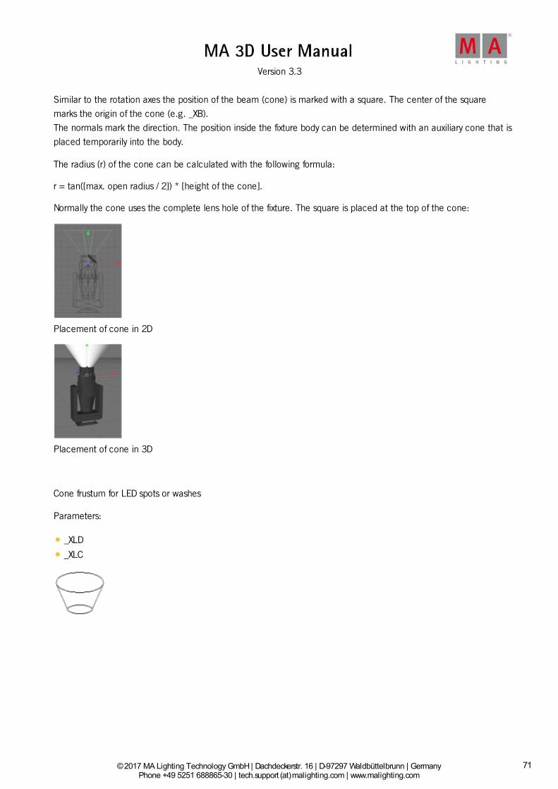
© 2017 MA Lighting Technology GmbH | Dachdeckerstr. 16 | D-97297 Waldbüttelbrunn | GermanyPhone +49 5251 688865-30 | tech.support (at)malighting.com | www.malighting.com
Version 3.3
1
Similar to the rotation axes the position of the beam (cone) is marked with a square. The center of the squaremarks the origin of the cone (e.g. _XB).The normals mark the direction. The position inside the fixture body can be determined with an auxiliary cone that isplaced temporarily into the body.
The radius (r) of the cone can be calculated with the following formula:
r = tan([max. open radius / 2]) * [height of the cone].
Normally the cone uses the complete lens hole of the fixture. The square is placed at the top of the cone:
Placement of cone in 2D
Placement of cone in 3D
Cone frustum for LED spots or washes
Parameters:
_XLD
_XLC
71

© 2017 MA Lighting Technology GmbH | Dachdeckerstr. 16 | D-97297 Waldbüttelbrunn | GermanyPhone +49 5251 688865-30 | tech.support (at)malighting.com | www.malighting.com
Version 3.3
1
At LED spots with flat housings the light beam is a cone frustum.This needs 2 parameters (squares) for the beam
LD marks the diameter of the beam output.
LC marks the clipping plane of the beam where the beam is cut.
The direction of the beam is marked via the normals.
Placement of cone frustum in 3D
The upper square shows the _XLD square and the lower square shows the _XLC square where the beam is cut.
72
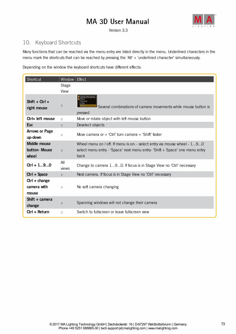
© 2017 MA Lighting Technology GmbH | Dachdeckerstr. 16 | D-97297 Waldbüttelbrunn | GermanyPhone +49 5251 688865-30 | tech.support (at)malighting.com | www.malighting.com
Version 3.3
1
10. Keyboard Shortcuts
Many functions that can be reached via the menu entry are listed directly in the menu. Underlined characters in themenu mark the shortcuts that can be reached by pressing the 'Alt’ + 'underlined character’ simultaneously.
Depending on the window the keyboard shortcuts have different effects:
Shortcut Window Effect
StageView
Shift + Ctrl +right mouse
:: Several combinations of camera movements while mouse button ispressed
Ctrl+ left mouse :: Move or rotate object with left mouse button
Esc :: Deselect objects
Arrows or Pageup-down
:: Move camera or + 'Ctrl’ turn camera + 'Shift’ faster
Middle mousebutton- Mousewheel
::Wheel menu on / off. If menu is on: - select entry via mouse wheel - 1…9…0select menu entry - 'Space’ next menu entry- 'Shift + Space’ one menu entryback
Ctrl + 1…9…0Allviews
Change to camera 1…9…0. If focus is in Stage View no 'Ctrl’ necessary
Ctrl + Space :: Next camera. If focus is in Stage View no 'Ctrl’ necessary
Ctrl + changecamera withmouse
:: No soft camera changing
Shift + camerachange
:: Spanning windows will not change their camera
Ctrl + Return :: Switch to fullscreen or leave fullscreen view
73

© 2017 MA Lighting Technology GmbH | Dachdeckerstr. 16 | D-97297 Waldbüttelbrunn | GermanyPhone +49 5251 688865-30 | tech.support (at)malighting.com | www.malighting.com
Version 3.3
1
11. MA 3D FAQ
Here you find frequently asked questions from users regarding the MA 3D.
Question/Problem SolutionHow can I change the model ofa fixture?
Select the model, right click on it, select change model. The Change Modelwindow opens.
How can I use grandMA series 1with MA 3D.
Since version MA 3D v3.0.0.5, the MA 3D is not compatible with the grandMAseries 1 anymore.
Download MA 3D version 2.9.1.1 on www.malighting.com.Can I open show files saved inan older version of MA 3D, in anewer version?
Yes, you can always open show files saved in older versions in the latestversion.
Can I open show files saved in anewer version of MA 3D, in anolder version?
No, download the latest version on www.malighting.com.
Can I run the MA 3D and the MAVPU on the same computer?
No, the MA 3D and the MA VPU at one computer need too many resources.
How can I disable screens in thefull screen mode?
Go to File in the menu bar, select Settings, select the category Full Screen.Right mouse click on the screen you like to disable for the full screen mode.Click on Enabled.
Can I run the MA 3D and thegrandMA2 onPC on the samecomputer?
Yes, use the default IP address. Refer to, Create a Session.
How can I use MA 3D on anApple MacBook?
Boot your MacBook in windows, using Bootcamp.
Can I import .dxf or .dwg files inMA 3D?
No, MA 3D supports only .3ds files. Convert the .dxf or .dwg files in .3ds.
How can I import a .3dsenvironment into MA 3D?
Go to File in the menu bar, select Import, select Import 3D Model. The MA3D Import window opens. This is used to import .3ds files.
How can I change meters intofeet?
Go to View in the menu bar, select the Assets window and the Propertieswindow. Select in the Assets window, grandMA2 and Units. Change the unitin the Properties window.
Are there any information aboutupdates and news?
Yes, get registered for the newsMAIL and techMAIL on www.malighting.com.
74

© 2017 MA Lighting Technology GmbH | Dachdeckerstr. 16 | D-97297 Waldbüttelbrunn | GermanyPhone +49 5251 688865-30 | tech.support (at)malighting.com | www.malighting.com
Version 3.3
1
12. Index3D 7.3.5. 9.3.
3D import model 9.5.
3D Modeling 9.7.
3D modeling workflow 9.1.
a 9.3.
Action 7.3.2.
Arrangement 7.3.3.
Assets 7.4.
Assigning of Models to Fixture Types 9.6.
Automated Import 9.8.
Axes 9.9.1.
Bar 7.1.4. 7.1.5. 7.1.6. 7.11.
Beam 9.9.4.
Beam of Light 9.9.4.
Checklist 9.7.
Connection 5.1.
Coordinate system 6.2.
Create a session 5.3.
Creation 9.3.
Creation of a 3D Model 9.3.
Data Management 6.
Database 7.6.
Download 4.2.
Duplicate 7.3.4.
Edit 7.1.3.
FAQ 11.
File Menu 7.1.1.
First Steps 5.
Fixture Types 8.
Functions 7.1.4.
Hardware 5.1.
help 1.
Help 7.1.7.
Import 9. 9.8.
Install 4.
Installation 4.2.
Int
Intro 3.
Introduction 3.
Invite session members 5.3.
75

© 2017 MA Lighting Technology GmbH | Dachdeckerstr. 16 | D-97297 Waldbüttelbrunn | GermanyPhone +49 5251 688865-30 | tech.support (at)malighting.com | www.malighting.com
Version 3.3
1
Join a session 5.3.
Keyboard 7.3.2.
Keyboard Shortcuts 10.
Layout 7.12.
Light 9.9.4.
Linear Axes 9.9.3.
Load show 5.2.
MA 3D fixture model creation 9.4.
MA3D 11.
Main 7.3.
Master 6.1.
Master/Slave 6.1.
Materials 7.7.
Media 7.6.
Menu 7.1.2. 7.1.3. 7.1.4. 7.1.5. 7.1.6.
Menu Bar 7.1.
Model 9.3.
Modeling 9.
Models 9.2.
Mouse 7.3.2.
Moving 7.9.
objects 7.3.3.
Objects 7.3.5.
of 7.3.3. 9.3.
Of 9.9.4.
Parameters 9.9.
Paths 7.9.
Player 7.8.
Principles 9.2.
Program Surface 7.
Properties 7.5.
Requirements 4.1.
Rotation 9.9.2.
Rotation Axes 9.9.2.
Session 5.3.
Sessions 7.10.
Settings 7.1.2.
Showfile 5.2.
Slave 6.1.
Stage 7.3.1.
Status 7.11.
76

© 2017 MA Lighting Technology GmbH | Dachdeckerstr. 16 | D-97297 Waldbüttelbrunn | GermanyPhone +49 5251 688865-30 | tech.support (at)malighting.com | www.malighting.com
Version 3.3
1
symbols 2.
Symbols used 2.
System 4.1.
technical help 1.
Technical support 1.
Toolbar 7.2.
Tools 7.1.5.
Uninstall 4. 4.3.
Video 7.8.
View 7.1.6. 7.3.1.
Windows 7.3. 7.12.
77