version 17 - sierra- · pdf fileevery use beyond the license or the lack of such license is a...
TRANSCRIPT

User’s Manual
Hot Fix
ERAVersion 17

© Sierra Technology Group S.A., 2016
This work has been registered according to the law. All rights reserved. Total or partialreproduction of this software, its physical media and/or its manuals, by any procedure and/or forany purpose whatsoever, is strictly prohibited.
HOT FIX ERA software can only be run on a computer by those authorized to do so by meansof a License Agreement. Every use beyond the license or the lack of such license is a violationto the author’s Intellectual Property rights, constituting a crime according to local laws andinternational treaties protecting Copyrights.
This manual is not for sale. It is available at no charge to users that acquire the license to useHOT FIX ERA software.
Information on this manual is subject to change without notice. Due to ongoing product updates,features and other functions may have been modified, replaced or added, including but notlimited to manuals, operating guides, quick guide charts, help/training material, etc. Although abig effort was made to ensure this manual is complete and correct, Sierra Technology Group donot warranty that the products behavior reflect the descriptions contained in this manual.
Modules, functions, features and components may vary according to thelevel of software or software configuration acquired. Modules, functionsfeatures and components mentioned in this manual may be included oroptions for your software product.
This manual has been created with the only purpose of making easier thelearning process of this product.
SIERRA, STITCH ERA, DESIGN ERA, HOTFIX ERA and ERA EXPLORER are marks andregistered trademarks of Sierra Technology Group S.A.
Other brands and their products are trademarks or registered trademarks of their respectiveholders.
1st. edition. Printed in Buenos Aires, September 2016Edited by Sierra Technology Group S.A.
Rivera Indarte 565 (1406), Buenos Aires, Argentina.Ver 17.00-01-EN

Editorial
Welcome
Thank you and congratulations for choosing a product from our multimedia garment decorationsuite, Design Era.We have put our best effort developing this product, as we have been doing for the last 20years, to always offer you the most advanced and competitive system on the market.We hope you enjoy it.
About this Manual
Design Era is a multimedia garment decoration suite currently integrated by two products, StitchEra, a full featured embroidery design system and Hotfix Era, a powerful design productfocused on garment decoration with thermofixed materials like rhinestones and sequins.
Hotfix Era allows you to create impressive designs quickly and easily. The advanced user interfase, unique in the market for this kind of product, is based oncontextual ribbons that displays, all the time, just the tools you need to work with the selectedobject, no matter if it is a raster image, a vector graphics or a hotfix object.The Universal Selection Tool simplify the way you work: just one tool to select almost any typeof object.Powerful artwork tools let you use raster images and vector graphics and convert them to hotfixobjects directly with a few clicks.Several styles for beads placement, design simulation with a beads library with more than 3000elements using realistic models with all their shines and texture, are just a few of the featuresyou are about to discover.
Chapters 1 and 2 are dedicated to introduce some notions about the hotfix technique, the userinterfase and the conceptual elements on which the product is based.Chapter 3 includes information about the tools for working with artwork graphics: raster imagesand vector files and objects.Chapter 4, probably one of the most important ones, is focused on hotfix objects creation andedition.Chapter 5 is dedicated to a very powerful Hotfix Era object: TextsChapter 6 contains information related with the several output modes available for differenthotfix production techniques: manual placement, stencils produced with vinyl or laser cuttersand automatic setting machines.Finally, Chapter 7 shows how to work with an advanced creation tool called Smart Design.

Page intentionally left blank

Index
HotFix ERA User's Manual
Con t en t s
Chapter 1 – HotFix ERA BasicsStarting HotFix Era ..............................................................................2
Walking around the User Interface.....................................................4
Artwork Tab Tools, organization........................................................10
Hotfix Tab Tools, organization...........................................................12
Understanding Working Modes..............................................................14
Design Creation.............................................................................15
Object Editing................................................................................19
Smart Design................................................................................20
Hotfix Editing................................................................................21
Common Tools...............................................................................21
Views Panel – Object Manager..................................................22
Catalog.................................................................................23
Chapter 2 - Visualization ToolsThe File Page.........................................................................................3
File - Open........................................................................................3
New .........................................................................................3
Open a Design Document............................................................3
Import......................................................................................4
Recent files................................................................................4
File - Save.........................................................................................5
Save ........................................................................................5
Index - 1

Export......................................................................................5
File - Information...............................................................................6
Information...............................................................................6
Share.......................................................................................6
Product Calculation.....................................................................6
File – Print.......................................................................................12
File – Options...................................................................................16
Preferences Setup.....................................................................16
Customizing Shortcuts...............................................................19
Keyboard Shortcuts...................................................................20
File – Account..................................................................................21
Learning about the different Ribbons.......................................................21
The Home ribbon..................................................................................22
Open......................................................................................22
Catalogs..................................................................................23
Undo and redo.........................................................................25
Clipboard................................................................................25
Format....................................................................................26
Work Area (Pages and Hoops)....................................................27
Output options.........................................................................29
System options........................................................................30
The View ribbon....................................................................................31
Zoom Tools......................................................................................31
Draw Mode......................................................................................33
Reference tools................................................................................35
Snap Modes.....................................................................................35
Synchronized Windows......................................................................36
Simulation View...................................................................36
Satellite View......................................................................37
Miscellaneous...................................................................................38
Measure Tool.......................................................................39
Auxiliary Toolbar...................................................................................40
Create Sections................................................................................40
Select Object...................................................................................40
Index - 2

Smart Design...................................................................................40
Grid................................................................................................41
Guidelines.......................................................................................41
Show/Hide design references.............................................................43
Traffic Lights....................................................................................44
Hotfix pieces library...............................................................................47
Beads Library......................................................................48
Quick Hotfix Selection tool....................................................49
Bead Gallery.......................................................................50
Bead bar behavior for existing and new designs.......................50
Background color and fabric..................................................51
Chapter 3 - Images and VectorsWorking with Raster Images.....................................................................3
Supported image formats.......................................................3
Open image.......................................................................................4
Capture Image from Scanner...............................................................5
Scale, rotate and move images manually..................................7
Scale image & Shape..........................................................................8
Properties...........................................................................10
Image Modes: Linked and Embedded......................................10
Using Raster images as.....................................................................11
Save...............................................................................................12
Vectorize. Image to figure..................................................................12
Step 1 - Clean the image......................................................13
Step 2 - Vectorize................................................................15
Working with Vectors.............................................................................17
Supported vector formats.....................................................17
Open a Vector File............................................................................18
Get Vector from CorelDraw and Illustrator...............................18
Paste Enhanced Metafile.......................................................18
Create vector figures.........................................................................19
Shapes...............................................................................19
Editor.................................................................................19
Index - 3

Vectors based on TrueType texts............................................20
Editing Vector figures........................................................................20
Vector Objects Selection ......................................................20
Scale and Rotate graphically..................................................22
Reshaping Vector Objects......................................................24
Combining vectors (Shaping)..............................................................25
Group & Ungroup Vectors...................................................................26
Ungroup and Ungroup all......................................................26
Alignment...........................................................................28
Vector Repetitions.............................................................................28
Export Vector Images........................................................................30
Using Vector images as......................................................................31
Chapter 4 - Creating Hotfix DesignsHotFix ERA Objects...................................................................................3
About Nodes......................................................................................3
Paths................................................................................................5
Areas................................................................................................6
Areas with Hotfix Uniform Fill.........................................................7
Areas with Hotfix Inner Ring Fill.....................................................8
Areas with Hotfix Flexible Fill........................................................10
Areas with Hotfix Flat Fill.............................................................11
Areas with Hotfix Grading Fill.......................................................12
Areas with Hotfix Textures...........................................................14
Areas with Hotfix Spectacular Fill..................................................17
Areas with Hotfix Outer Ring Fill...................................................19
Ray Hotfix Column......................................................................22
Path and Areas with Hotfix Assorted Fill.........................................24
Manual Hotfix..................................................................................25
Hotfix Texts.....................................................................................25
Creating Hotfix objects............................................................................25
Manual Digitizing..............................................................................26
Assisted Digitizing: Autotrace.............................................................26
Index - 4

Automatic Digitizing: Auto Complete............................................28
Digitizing using Geometric Shapes.......................................................28
Editing Hotfix objects........................................................................29
Object Selection tools........................................................................29
Hotfix piece edition tool.....................................................................30
Working with Hotfix Objects Blocks............................................................31
Repetitions......................................................................................33
Effects on Hot fix objects...................................................................33
Move Random..........................................................................34
Color Random...........................................................................34
Color Blending..........................................................................35
Grayscale Photo Stone...............................................................35
Color Photo Stone.....................................................................37
Whirl.......................................................................................38
Sphere....................................................................................39
Grid Transformation...................................................................39
Object Manager and Object Inspector.........................................................40
Object Manager................................................................................40
Object Inspector...............................................................................41
Sorting pieces.........................................................................................41
Cleaning overlapped pieces..........................................................................42
Importing YNG files...........................................................................43
Importing PLT files............................................................................45
Importing DST files...........................................................................46
Chapter 5 - Hotfix TextsHotfix Text.............................................................................................2
HotFix ERA Text Objects......................................................................2
Text object types...................................................................2
Creating Texts: Text ribbon..................................................................3
Example: Creating simple text in 3 steps..................................3
Editing Texts......................................................................................5
Editing Text Properties............................................................5
Editing Text Geometry............................................................6
Text Transformations...........................................................................6
Index - 5

Transformation types.............................................................7
Using Transformations............................................................7
Exploding Texts (Split Hotfix).............................................................10
Assemble Hotfix Beads......................................................................11
Disassemble Hotfix Object.................................................................12
Chapter 6 – Hotfix OutputHotfix ERA Outputs.............................................................................2
File Formats..........................................................................2
Send to machines and devices.................................................3
Printing................................................................................4
Exporting Hotfix files...........................................................................4
Machine Brands and Models Supported.....................................5
Hotfix Exporter......................................................................5
Exporting to HPGL, Metafile and DXF Files..............................................7
Export to HPGL File................................................................7
Export to Windows Metafile and DXF formats.............................8
Sending Hotfix to machines and devices................................................9
Sending information to CAMS machines..................................10
Sending information to Windows Cutters.................................12
Sending information to HPGL compatible devices......................13
Sending information to Engravers...........................................14
Printing Hotfix Technical Sheets..........................................................15
Printing Hotfix Presentation Sheets......................................................17
Chapter 7 – The SMART DESIGN toolSmart Design.........................................................................................2
Smart Design in Objects Creation mode.................................................2
Smart Design in Object Editing mode....................................................3
Smart Design in Vectors Digitizing mode................................................5
Index - 6

Chapter 1
HotFix ERA Basics
Con ten t s :
Starting HotFix Era ......................................................................................2
Walking around the User Interface......................................................4
Artwork Tab Tools, organization........................................................10
Hotfix Tab Tools, organization...........................................................12
Understanding Working Modes......................................................................14
Design Creation..............................................................................15
Object Editing.................................................................................19
Smart Design.................................................................................20
Hotfix Editing.................................................................................21
Common Tools...............................................................................21
Views Panel – Object Manager.......................................................22
Catalog......................................................................................23

Page intentionally blank

HotFix Era Basics
Starting HotFix Era When you start HotFix Era from the desktopshortcut icon or from the programs list of the startmenu you can see the software splash screen. If itis the first time you run the application, it will appearthe welcome screen as shown in the picture on theright, showing at the bottom the legal notes. Take acouple of minutes to read it, and if you agreed withthe terms and conditions of the license, then click'Yes' to complete the HotFix ERA load.
Check in the “Please, do not ask me again" box, ifyou want to avoid this step the next time you run theprogram.
Once the program is loaded, the first screen isdisplayed.
This is the “File-Open” page.
The other functions, like Save, Info and Print, will become available in this tab as soon as you opena file on screen.
This chapter will explain how the available tools are organized (i.e. how to navigate within the program).
It is very important to recognize each part of the program screen. To do so, on the “File-Open”tab, under the “New” section, click on “Blank Design Document”.
1 – 3

HotFix ERA – User's Manual
(1) On the top of the screen is the TITLE BAR. That bar shows the application name (HOTFIX
ERA) and it may also show small buttons, which are shortcuts for several program
functions. This is the Quick Access Toolbar.
It contains very frequent used commands like Save,
Undo/Redo, Clipboard (Cut, Copy, Paste and
Delete) and Generate (recalculate hotfix objects).
This handy element is always visible and avoids you to switch ribbon tabs or access the
Application menu for accessing these commands.
(2) Below the TITLE BAR, is the TABS BAR. That bar shows the names of groups of thematic
functions. You will find the tabs FILE, HOME, ARTWORK, HOTFIX and VIEW.
(3) Below the TABS BAR is the RIBBON BAR. This bar shows the available tools for the
selected tab (group name). When the tab is changed, the ribbon changes accordingly.
(4) Below the RIBBON BAR you will find a bar which we will call AUXILIARY BAR where you
have some useful functions handy like Create Sections; Select Objects; Smart Design;
1 – 4

HotFix Era BasicsZoom tools; and some visual aids like guidelines, grid and subgrid; object guides and
hide/show commands. On the right side of this bar there are some tabs to show/hide/block
different design layers (Auxiliar; Screen Printing; Cutter; Embroidery; Hotfix).
(5) Below the previous bar is the DOCUMENT BAR. This bar also includes tabs. Each tab
represents a document (a design) and has a different color.
(6) Below the DOCUMENT BAR is the WORKSPACE. When a document tab is selected, this
space is the area where the design is displayed.
Walking around the User Interface
Before learning each part in detail, let´s navigate around the program for a while, in order tounderstand the program organization and make it easier to find the tools.
Click on the tab NEW DOCUMENT of the document bar.
Several things occur:
A new design document is created (name Design1)
An empty workspace is displayed
All tabs appear in thetabs bar (HOME tab is selected)
The ribbon bar shows the tools/functions of the HOME group
1 – 5

HotFix ERA – User's Manual
Click on the HOTFIX tab and see how the tools/functions of that group appear on the ribbon bar.
Then click on the VIEWtab and see how the tools/functions of that group appear on the ribbon bar.
These are not the only available tabs of the TABS BAR. According to the activity (designcreation, editing, etc) new CONTEXT BARS may appear.
As an example:
Click on the artwork tab
Click on the Shapes tool and select the advanced shape which tooltip says AAS_013.
Click on any place of the workspace and (without releasing the mouse button) drag the mouse to other position and then release the mouse button.
You can see that:
1 – 6

HotFix Era Basics
A geometric shape was created.
It is selected.
New context tabs are available (Vector, Layout) with more tools/functions available. Those tools/functions will apply to the selected shape.
This was only an example of how context tabs become available according to the activity andaccording to the selected objects. The same concept will apply to hotfix objects. The tools arewell organized and become available when they are required.
Let´s continue with the FILE TAB.
In the File-Open group you will find three different sections:
New, Open and Import.
Inside the New section you have the commands to create a new design document:
Blank Design Document; Simple Wizard; and Complete Wizard Hotfix.
Inside the “Open” section you have the command “Open a Design Document”.
Finally, inside the “Import” section, you have the commands: A Graphic File; and A Hotfix file.
1 – 7

HotFix ERA – User's ManualOn the far right you will find the samples of the recently opened documents, which a littlethumbnail and the physical location of the file. Double click on any to open it.
Section FILE-SAVE includes functions to save (store) the active design (current designdocument) in the system native format: “Save the Design Document” and “Save... as”;
and / or export the design (Vector, Bitmap, or Hotfix) in any compatible machine format, send the active design directly to the machine for production, etc.
Section FILE-INFORMATION includes several functions related to the properties of the active design (Infocard); also
allows you to Share yourdesign in Social Networks;
and lets you make estimatesof hotfix pricing andproduction (optionalfeatures)
1 – 8

HotFix Era Basics
Section FILE-PRINT includes several printing functions for Hotfix designs.
Section FILE-OPTIONS includes functions related withthe setting of the software application (it is not related with the active design itself).
1 – 9

HotFix ERA – User's Manual
Click on “Preferences Setup”. A dialog box will open.
On the left panel, click onthe Application group.
The right side will show the contents of it.
Click on Language to unfold a list of available options.
Then choose the selected option from the setting list (right side).
This function will require to exit the program, and restart it.
There are several aspects of the user interface and system behavior you may configureaccording to your preferences. The Options and Preferences box groups all the configurableitems in HotFix ERA.
Let´s return to the FILE tab, last section.
Section FILE-ACCOUNT includes the information of the licensed software product, activation status,registered user information and Contact links.
Up to now we have described the basics of the user interface. Following sections will explainthe mentioned parts with more detail.
1 – 10

HotFix Era Basics
Artwork Tab Tools, organization
Click on the tab NEW DOCUMENT of the document bar.
A new tab will be created (Design1) in the document bar,
The workspace (active design) is empty.
Click on the ARTWORK tab.
The MAIN ARTWORK TAB (and main artwork ribbon bar)will appear on screen.
Click on the Shapes tool and select a Basic Shape (rounded rectangle).
Click on any place of the workspace and (without releasing the mouse button) drag the mouse to another position and then release the mouse button.
The corresponding shape willappear on the screen.
1 – 11

HotFix ERA – User's Manual
ARTWORK
Artwork is the part of the design document which includes the set of graphic elements of thedesign (raster images or vector graphics). In the example above, only the created vector objectis the artwork of our design.
ARTWORK CONTEXT TABS (1)
More tabs are visible in the tabs bar. The new tabs are context tabs because they depend onthe current activity of the program. As we are working with Vector Artwork (graphic shapes /figures), then related (or context) tabs are available: VECTOR and LAYOUT.
ARTWORK RIBBON BARS (2)
When you select each of those context tabs, the ribbon displays all the related functionsgrouped in sections. The functions will apply to the object selected on the workspace. In thismoment you are able to edit any of the vector objects present on your design or create morevector objects. These functions will be explained later.
ARTWORK AUXILIAR BAR (3)
Below the RIBBON BAR you will find a bar which we will call the AUXILIARY BAR where youhave some useful functions handy like Create Sections; Select Objects; Smart Design; Zoomtools; and some visual aids like guidelines, grid and subgrid; object guides and hide/showcommands. On the right side of this bar there are some tabs to show/hide/block different designlayers. The first led, Auxiliar, corresponds to the image/s you have on screen.
ARTWORK COLOR BAR (4)
On the left of the workspace, a vertical toolbar shows some tools related to the color palette ofthe artwork and other tools.
If you want to set the color to create an object, or edit (modify) the color of an existing object,you can press the left mouse button on any color of the color palette to set the fill color (area)and/or the right mouse button to set the border color (line).
If you want to change the color palette (colors displayed on the left of the workspace) you canset each color with the color palette function (there is a palette icon) in the artwork color bar.
These functions will be explained later.
The same concept of new context tabs with related functions in the ribbon bars apply to Hotfixobjects. The tools are well organized and become available when they are required.
1 – 12
HotFix Era Basics
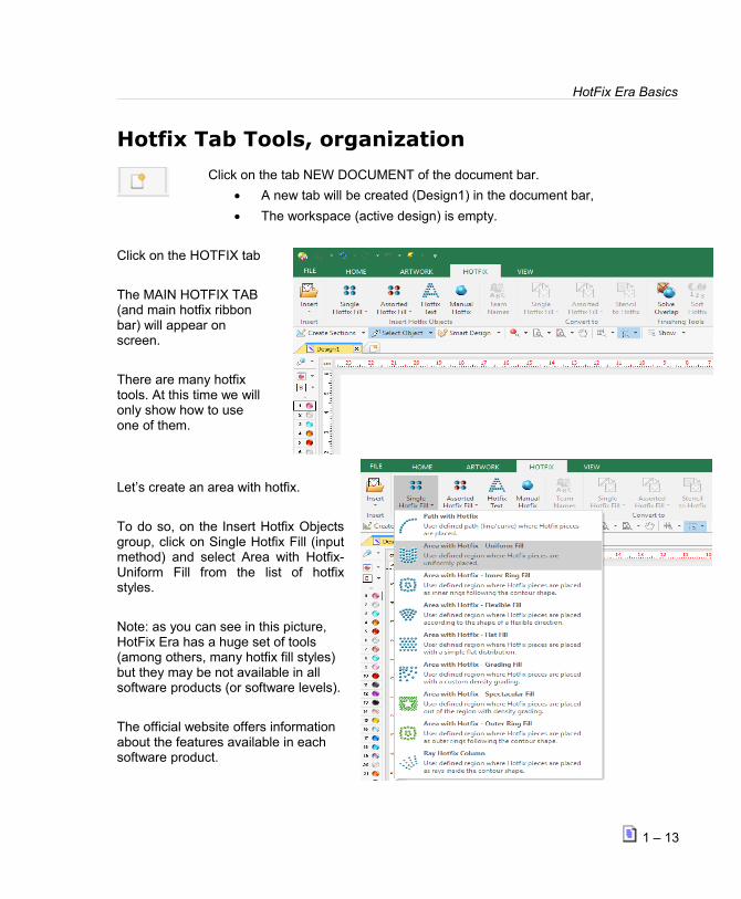
Hotfix Tab Tools, organization
Click on the tab NEW DOCUMENT of the document bar.
A new tab will be created (Design1) in the document bar,
The workspace (active design) is empty.
Click on the HOTFIX tab
The MAIN HOTFIX TAB (and main hotfix ribbon bar) will appear on screen.
There are many hotfix tools. At this time we willonly show how to use one of them.
Let’s create an area with hotfix.
To do so, on the Insert Hotfix Objectsgroup, click on Single Hotfix Fill (inputmethod) and select Area with Hotfix-Uniform Fill from the list of hotfixstyles.
Note: as you can see in this picture, HotFix Era has a huge set of tools (among others, many hotfix fill styles) but they may be not available in all software products (or software levels).
The official website offers information about the features available in each software product.
1 – 13

HotFix ERA – User's Manual
Click (mouse left button) on several points of the workspace. To close an object, simply locatethe last point above the first point. The system will close the area automatically. To close itmanually, you can either press the Enter Key or click the mouse center button. This will confirmthe hotfix object and will show the corresponding beads (rhinestone, sequin/spangle).
HOTFIX
Hotfix is the part of the design document which includes the rhinestone and sequin/spanglesobjects. In this case, only the created hotfix object is our hotfix design.
HOTFIX CONTEXT TABS (1)
More tabs are visible in the tabs bar. The new tabs are context tabs because they depend onthe current activity of the program. As we are working with Hotfix, then related (or context) tabsare available: HOTFIX AREA BODY, BORDER & LAYOUT.
HOTFIX RIBBON BARS (2)
The context ribbon bar shows the group of functions of Hotfix Area input method, with UniformFill. There are many many context ribbon bars as there are many input methods and hotfix fillstyles. The functions will apply to the hotfix object selected on the workspace or to a new hotfixobject under construction. These functions will be explained later.
HOTFIX AUXILIAR BAR (3)
Below the RIBBON BAR you will find a bar which we have called AUXILIARY BAR where youhave some useful functions handy like Create Sections; Select Objects; Smart Design; Zoomtools; and some visual aids like guidelines, grid and subgrid; object guides and hide/show
1 – 14

HotFix Era Basicscommands. On the right side of this bar there are some tabs to show/hide/block different designlayers. The hotfix led, corresponds to the hotfix object/s you have on screen.
HOTFIX BEADS BAR (4)
To the left of the workspace, there's a vertical toolbar that shows some tools related to thebeads (rhinestone, sequin/spangle) palette of the hotfix design and other tools.
If you want to set the type of bead to create a hotfix object or edit (modify) the type of bead ofan object, you can press the mouse left button on any bead to select that bead type.
If you want to change the beads palette (beads types displayed on the left of the workspace)you can set each bead with the beads palette function (there is a palette icon) in the hotfixthreads bar.
These functions will be explained later.
Understanding Working ModesThere are 4 main working modes:
Design Creation
Also known as Digitizing or Object Creation.
In this working mode, users are able to insert many objects in the design.
There are many kind of objects. We classify them in 2 types:
Graphic/Vector Objects
Hotfix Objects
1 – 15

HotFix ERA – User's ManualExample:
Create a new design document as described previously
Select the HOTFIX tab.
The program will show the MAIN HOT FIX ribbon bar.
Click on the Hotfix Objects group:
Single Hotfix Fill
The program will show the available Fill Styles.
Select the Hotfix Style:
Area with Hotfix – Uniform Fill
The program will show the Area with Hotfix –Uniform Fill ribbon bar.
Let's make some adjustments on the properties of the area we are going to do, just by workingon the ribbon. These adjustments will apply to the objects we are creating.
1 – 16
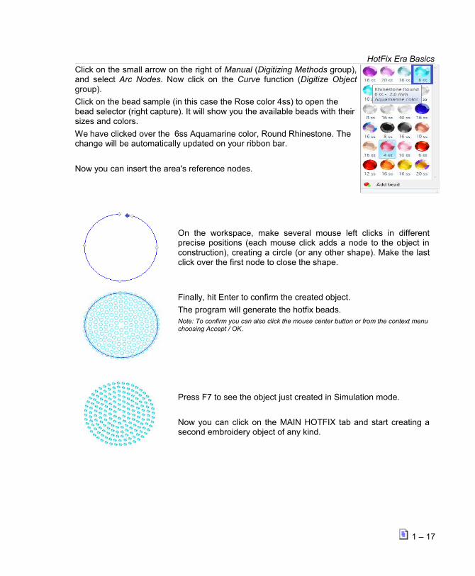
HotFix Era BasicsClick on the small arrow on the right of Manual (Digitizing Methods group),and select Arc Nodes. Now click on the Curve function (Digitize Objectgroup).
Click on the bead sample (in this case the Rose color 4ss) to open the bead selector (right capture). It will show you the available beads with theirsizes and colors.
We have clicked over the 6ss Aquamarine color, Round Rhinestone. The change will be automatically updated on your ribbon bar.
Now you can insert the area's reference nodes.
On the workspace, make several mouse left clicks in differentprecise positions (each mouse click adds a node to the object inconstruction), creating a circle (or any other shape). Make the lastclick over the first node to close the shape.
Finally, hit Enter to confirm the created object.
The program will generate the hotfix beads.Note: To confirm you can also click the mouse center button or from the context menuchoosing Accept / OK.
Press F7 to see the object just created in Simulation mode.
Now you can click on the MAIN HOTFIX tab and start creating asecond embroidery object of any kind.
1 – 17

HotFix ERA – User's Manual
Different ways of selecting the same object kind.
You have several ways of enabling the same Hotfix creation tool object:
1 From the Hotfix ribbon > Insert HotfixObjects group > choose the type tounfold the list of available styles. Clickon the desired one.
2 Selecting it from the Design Creationmode button.
Click on the small arrow on the right ofthe Design Creation mode button.
Then select the object type and finallythe style to use from the pop-upmenus.
1 – 18

HotFix Era Basics3 Selecting it from the Smart Design
tool.
Click on the Smart Design button.
Then select the object type and stitch style to use from the Smart Design tool.
Digitizing Modes:
Up to now we have used only the manual digitizing mode (click node by node). There are somedetails you must know about this digitizing mode, and you must also know that there are otherdigitizing modes (they may vary according to the software product):
Manual Digitizing (arc curves, bezier curves)
Automatic Digitizing (auto-trace, auto-complete, etc)
Geometric Shapes (regular shapes, auto-shapes)
Free Hand Digitizing
These digitizing modes will be explained in following chapters.
Conclusion. Important Concept:
An object is the simplest element we can insert in a design. The object is defined by ashape (contour, holes, etc) with auxiliary elements, and by the properties.
We insert hotfix objects in a design because it is easier and faster than insertingstones or sequins one by one. When you insert a simple circle and define the hotfixproperties (stone spacing, etc) the program converts that object into stones or sequins.
If you save the design in the system native format DSG, that format keeps all theinformation of the objects (shapes, properties, etc.). You may then edit (modify theshape and properties) at any moment easily.
1 – 19

HotFix ERA – User's Manual Instead, when you save the design in a machine file format (also known as expanded
formats), that format only knows about stones/sequin, and the useful information of theobject is lost.
System formats include Hotfix Objects.
Expanded formats (machine formats) include Hotfix beads.
Object Editing
This is the second working mode. When you have a design made by several objects, you areable to edit every characteristic of those objects: You can change the shape of an object,enlarge reduce and move it, and modify each property in the same way you did when the objectwas created.
Press the Select Object tool (to enter the object editing mode).
Select an object or ablock of objects in theworkspace. A surroundingrectangle will cover theobject/s.
Now, you can execute any of the object editing functions, among others:
Move the object (drag and drop the rectangle)
Re-size the object (move the rectangle handlers)
Rotate the object (press the CTL key and move the rectangle handlers)
Change the shape of the object (drag and drop the nodes of the object)
Modify any of the elements of the object
Change any of the fill properties (from the ribbon bar, or from the object inspector)
After you edit a hotfix object, the program will re-generate the stones/sequins according to thenew object features.
1 – 20

HotFix Era BasicsAs explained, when the design is made of objects, then object editing is very powerful to modifyexisting designs. It uses the generation engine to rebuild objects. By contrast, hotfix editing(stone by stone) is more complicated, slow, and it doesn't use the generation engine of thissoftware to rebuild design parts.
Smart Design
This is the third working mode. This tool simplifies the steps and speeds up the object creationor edition process, as well as some functions related with the auto-digitizing feature over vectorobjects.
Press the Smart Design tool (to enter the Smart Design mode).
A window with the tabs Hotfix; Edition and Creationwill open.
Click on the Creation tab tosee the available tools to build a new object;
Click on the Edition tab andselect an object, to be able to...
...convert it from vector object into and embroidery (or Hotfix) object;
... convert the kind and fill of an embroidery (or Hotfix)object to a totally different one, among the available.
If your software product has both embroidery and hotfix features, this tool allows the conversionof embroidery objects into hotfix ones and viceversa.
This working mode will be explained in Chapter 7 - The Smart Design Tool.
1 – 21

HotFix ERA – User's Manual
Hotfix Editing
This is the forth working mode. Also knows as Expanded Editing. Sometimes you need to editstones on a hotfix design. Certainly HotFix ERA includes the tools for expanded editing.Expanded editing is required when the design is not made of objects, this is the case when thedesigns are imported from commercial machines file formats. However expanded editing canalso apply to objects if fine tuning is required.
Press the Edit Hotfix tool(entering to the hotfix editingmode).
Select a hotfix bead in theworkspace. It will be surroundedby a square.
The ribbon bar will showinformation about the position,angle and bead type.
Now, you can execute any of the hotfix editing functions, among others:
Move, delete or insert beads
Select blocks, then move, delete, rotate, copy & paste, etc.
Use the Repetitions group of functions (Duplicate and effects options).
Common ToolsThere are some useful tools that are always available no matter what tab is active. They arelocated in two groups: one above the working area which we will call Auxiliary toolbar and theother on the right edge of the working area, called Views Panel;
The one above the workspace area gathers the following functions: on the left: CreateSections, that allows to build new objects, graphic shapes, and hotfix; Select Object, used to
1 – 22

HotFix Era Basics
select one or more objects for edition; Smart Design, a great tool for quick object creation,edition and conversion (briefly explained in previous pages); and visualization tools likesimulation view, zooms, pan and hide/show options;
On the right you will find some very helpful led lights, one for each document type you areusing and each with its corresponding tab in the Document Map. You have Auxiliary;ScreenPrinting; Cutter; and Hotfix. They allow you to Hide, Show or Lock the objects that formyour design to easier your designing process.
Auxiliary toolbar will be explained in the next Chapter.
Views Panel – Object Manager
Located on the right side of the workspace area, the Views panel allows you to explore thestructure of your designs, that is, the sequence of entities the design is built of.
The main view is the Object Manager. It contains a panel with a map of the design, divided inobject types, and section by section, with predefined fill modes.
Below is the Object Inspector, which shows the complete list of properties to be able tocontrol, in detail, how the system will generate the beads for your hotfix designs.
When you click on a section on the Object Manager, the Object Inspector shows all the relatedproperties to the object selected.
Another important view is called Hotfix Objects. It shows aSequence of all the Hotfix Objects present in the design,and below it, a list of all the design´s hotfix beads.
The last view, called Vector Objects shows a list of all thevector objects present in the design.
1 – 23

HotFix ERA – User's Manual
Catalog
There's also another group gathered in a floating window thatremains open once you click on its access, named Catalog. Itis located on the HOME ribbon, INSERT group. It allowsgraphic browsing of all the media handled by your softwareso you have quick access to it. It´s divided in three panels.The upper one shows the media type: Images (Raster andVectors); Native Designs (DSG files); Hotfix Designs(machine format) and Motifs (predefined files ready to beused);
Having selected the media type, the second panel, named“Folders” shows the available folders on your computer.Navigate through your disk units and folders until you find theone needed. The third panel, named “Images”, will displaythe contents of the selected folder graphically.
Find the desired object and just drag it into the workspace toload it. Don’t worry about the object type, the system willrecognize it and will proceed properly.
1 – 24

HotFix Era BasicsPage left blank
1 – 25

Chapter 2
The File Page and Ribbons
1 . Con ten t s
The File Page..................................................................................................3
File - Open.........................................................................................3
New ..............................................................................................3
Open a Design Document..................................................................3
Import...........................................................................................4
Recent files.....................................................................................4File - Save..........................................................................................5
Save .............................................................................................5
Export............................................................................................5File - Information................................................................................6
Information.....................................................................................6
Share.............................................................................................6
Product Calculation..........................................................................6File – Print........................................................................................12
......................................................................................................15
File – Options....................................................................................16
Preferences Setup..........................................................................16
Customizing Shortcuts....................................................................19
Keyboard Shortcuts........................................................................20File – Account...................................................................................21
Learning about the different Ribbons................................................................21
The Home ribbon...........................................................................................22
Open............................................................................................22
Catalogs.......................................................................................23

Undo and redo...............................................................................25
Clipboard......................................................................................25
Format.........................................................................................26
Work Area (Pages and Hoops)..........................................................27
Output options...............................................................................29
System options..............................................................................30
The View ribbon............................................................................................31
Zoom Tools......................................................................................31
Draw Mode.......................................................................................33
Reference tools.................................................................................35
Snap Modes......................................................................................35
Synchronized Windows.......................................................................36
Simulation View.............................................................................36
Satellite View................................................................................37Miscellaneous....................................................................................38
Measure Tool.................................................................................39
Auxiliary Toolbar...........................................................................................40
Create Sections.................................................................................40
Select Object....................................................................................40
Smart Design....................................................................................40
Grid.................................................................................................41
Guidelines........................................................................................41
Show/Hide design references..............................................................43
Traffic Lights.....................................................................................44
Hotfix pieces library.......................................................................................47
Beads Library................................................................................48
Quick Hotfix Selection tool...............................................................49
Bead Gallery..................................................................................50
Bead bar behavior for existing and new designs..................................50
Background color and fabric.............................................................51

The File Page and Ribbons
In this chapter you will learn about the basic commands you need to open hotfix files and use thelarge set of visual tools available to explore the design, manipulate its colors, access detailedinformation and generate printouts.
The File PageOnce the program is loaded, the File Page will open.
The first screen to be displayed shows the File - Open commands. You have other commandsgrouped in the File page besides Open. They are Save; Information; Print; Options and Account.We will see them in detail in this chapter.
File - Open
From this command you can load all types of designs (expanded and condensed) into Hotfix ERA.
It offers several options to start your work, which are gathered within the following group names:
• New;
• Open a Design Document;
• Import;
• Recent Documents;
New
Blank Design Document: Opens a new working window ready to start working.
Simple Wizard: Use this option to create new designs by just indicating the designname, storage folder, design authoring information, classification, job order, and price.
Complete wizard Hotfix: This option will prompt you to specify design name, storagefolder, design authoring information, classification, job order, price, and hoop to beused. Some information is optional and other is required.
Open a Design Document
Open a Design Document: Displays an Open Design dialog so you can browse yourunits and folders and select the design (condensed format) you want to open, in a newworking window.
2 - 3

Hotfix Era – User's Manual
Import
A Graphic File: You can open a Raster or Vector Image into a new document, as wellas getting an image file directly from Corel DRAW or Adobe Illustrator.
A Hotfix File: Open an already made hotfix file into a new document.
Recent files
Shows a graphical preview of the last recent designs loaded, so you can double-click on any to quickly re-open it.
After you click on any of the available options, a window may open.
- You can browse your units using the left panel and the Look In control availablein the toolbar.
- You can switch the view mode to icons, list, details, several thumbnails mode, etc
- You can select the codes to be displayed or use the All Files filter to indicateHotfix ERA to display all types of embroidery files.
To open a design just double click on it (or select with one click and press the Open button).
2 - 4

The File Page and Ribbons
File - Save
From this command you can save (store) the active design (current design document) in thesystem native format, export the design in any compatible machine format, send the active designdirectly to the machine for production, etc.
It offers several options to start your work, which are gathered within the following group names:
Save
Save the Design Document: Save the Design Document to save a Design format filealso known as condensed file. You can save Sierra Designs (DSG files)
Save the Design Document as...: This option will save a copy of the working windowwith another name.
Export
Vector Graphics
Bitmap Graphics
Hotfix
When you click on any of the options, “Export As” will list the available choices.
2 - 5

Hotfix Era – User's Manual
When you finish your work with a condensed design, save it for the last time to keep the lastchanges made and use the Export command to prepare it to be sent to your machine.
If later, you need to make some changes, open the dsg file (condensed), make the changes,save the dsg file and export it again.
This procedure may sound too indirect at this point but, as you will discover in the followingchapters, dsg files are much easier and flexible to modify than expanded design files.
The whole idea is to work, all the time, with dsg files and export them into expanded files justbefore sending them to the machine.
Note 1: Hotfix Era offers an auto-backup feature that automatically saves the active design at a regular time interval (specified in File – Options - Preferences Setup – Project – General). However, it’s a good practice to save the design by yourself once you have complete a task you consider important during the design process.
File - Information
From this command you have access to four different groups that have to do with the designinformation, sharing and production calculation.
Information
◦ Design Properties (Infocard): Shows a summary of the design properties includinginformation of authoring and classification.
◦ Hotfix Properties (Infocard): Shows a summary of the hotfix properties.
Share
◦ Share the Design in Social Networks: You can upload the design on the work windowalong with a comment via Twitter.
Product Calculation
◦ Hotfix Database Price Setting: Allows setting the prices of hotfix to be used in costingcalculation.
◦ Hotfix Pricing: Calculate Hotfix design cost based on prices of hotfix configured.
We will see each one in detail.
2 - 6

The File Page and Ribbons
Information-Design Properties (Infocard)It is divided in three tabs: General; Job and Authory; Category.
General tabContains basic design file information such as design name, file name, storage path, file size,creation date, last edition date and file attributes.
Job and Authory tabUsing this tab you can add job order and design author Information.
Data related with job order includes order number, requesting and creation dates, customer nameand time used (computed automatically)
Author information includes design codification, owner, author, copyrights, etc.
Category tab
Last, the Category tab allows to establish information about Collection, Category and Keywordswhich will be assigned to the design. All this data will be very useful for those design saved in theDesign Library.
To add information follow these steps:
Collection – To add a new collection, clic on theellipsis button [···], which is marked on the leftfigure.
The Collection Editor box opens, type the nameand press the green check button to finish insertingit to the system, it will be listed in the Collection list,clic on the OK button to confirm the Collection justinserted.
2 - 7

Hotfix Era – User's Manual
Category – It is a hierarchy tree. To assign thedesign a determined category, simply select it fromthe list.
In the case the Category does not exist, enter theCategory Editor through the ellipsis button [...] andtype the adequate category.
From this box you can create and delete items andsub items through the corresponding buttons (seeleft figure).
Keywords - Keywords are intended for helping searches. A keyword is a descriptive word(normally just one word) related to the design thematic. A design may contain several keywords.You can add keywords using the Keyword editor (ellipsis button).
Information-Hotfix Properties (Infocard)It's divided in two tabs: General Information and Sequence.
General Information tab
It´s divided in two panels. Left panel includesgeneral design data such as Width, Height,number of different types of beads and Quantity.
The right panel shows a simulation view of thedesign.
2 - 8

The File Page and Ribbons
Sequence
Within this tab you will find on the left a sortedlist with a graphic view showing the beads colorin the design in the order they will be processed.
The thumbnails also contains information aboutthe bead diameter.
On the right you will find a simulated view of allthe design, but highlighting the bead type youselected on the left panel.
Share-Share the Design in Social Networks
This option allows you to upload the design that is on the work window to the Social Networks - Twitter.
You may add a comment along with the design.
Follow these steps:
With the design you want to upload on your active document windows, go to the File-Information tab, then to the Share group, and click on Share the Design in Social Networks.
Information-Product Calculation (Optional Feature)
Hotfix Era includes tools to prepare hotfix service quotations.
You can access these tools from the File – Information - Product - Calculation menu, andselecting any of the items: Hotfix Database Price Setting or Hotfix Pricing.
2 - 9

Hotfix Era – User's Manual
Hotfix Database Price Setting
This dialog box lets you add a price to any of the listed bead types, for a later use in pricingcalculations.
Use the Type, Shape and Size filters to be able to find a desired bead easily on the list.
From the Type list you canselect among Rhinestones,Rhinestuds, Nailheads,Sequins and Spangles.
From Shape you canchoose the geometry youare looking for among: Std-Heart; Std-Octagon; Std-Oval; Std-Rectangle; Std-Round; Rim-Round; Std-Square and Std-Star.
Once you selected thebead Type and Shape, youwill be able to find thedimensions available on theSize list.
2 - 10

The File Page and Ribbons
Once you find the desired bead, select it by checking its corresponding box. Insert the Volume(number) , and Price x Volume and press Apply. The system will automatically update theinformation on the list.
Hotfix Pricing
This tools is specialized to prepare hotfix service quotations based on design information, beadscount and price values you define.
To determine a price for your design follow these steps:
1. Open the hotfix design on screen.
2. From File > Information > Product Calculation , choose Hotfix Pricing.
3. The Hotfix Cost dialog box will open showing the total cost of the selected design.
If any of the items shown on the Hotfix Cost dialog box do not have Qty. and/or Price, or youwant to update any of the values, you can set them through any of the following ways...
• From the Hotfix Database Price Setting (previous page) …
but more directly...
• From Prices button, to open the Pricing window with only the beads used for theselected design. Select each type, insert Volume and Price, and press Apply.
• From Set price for selected bead button. On the Hotfix Cost dialog box, click on one ofthe items to highlight it. Upon pressing the button, the Set Price dialog box will open.Insert Volume and Price, and press Apply to update the information.
• From the Hotfix Cost dialog box, you can print the Pricing information of the design.
2 - 11
Hotfix Era – User's Manual
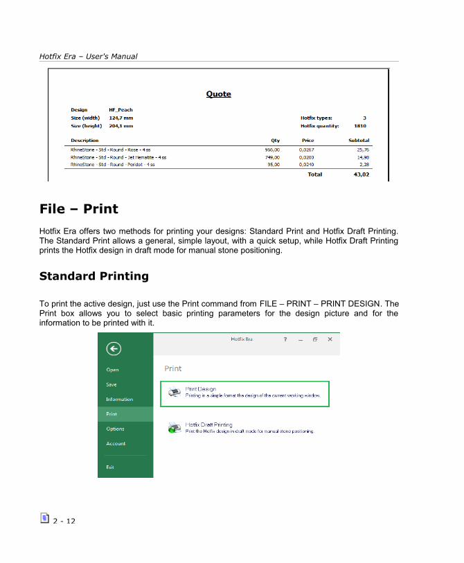
File – Print
Hotfix Era offers two methods for printing your designs: Standard Print and Hotfix Draft Printing.The Standard Print allows a general, simple layout, with a quick setup, while Hotfix Draft Printingprints the Hotfix design in draft mode for manual stone positioning.
Standard Printing
To print the active design, just use the Print command from FILE – PRINT – PRINT DESIGN. ThePrint box allows you to select basic printing parameters for the design picture and for theinformation to be printed with it.
2 - 12

The File Page and Ribbons
Scale: This parameter refers to the size of the design in the paper sheet. Use 100% to get a fullscale, 1:1 print out
Print rotated: When checked, the design is printed in landscape mode.
Print Hotfix - Simulation: When checked, the design is printed in simulation mode.
Print Design Information: Check this box to include an information area in the printout. Themarks Full file name, Customer and Owner allows you to set what extra information should beincluded.
Print Page Border: Check this mark to force a thin box to be printed all around the layout.
Note: Use the Preview button to check how the printout will look before printing. Use the controls at the lower right corner to control page margins and set printer preferences.
2 - 13
Hotfix Era – User's Manual
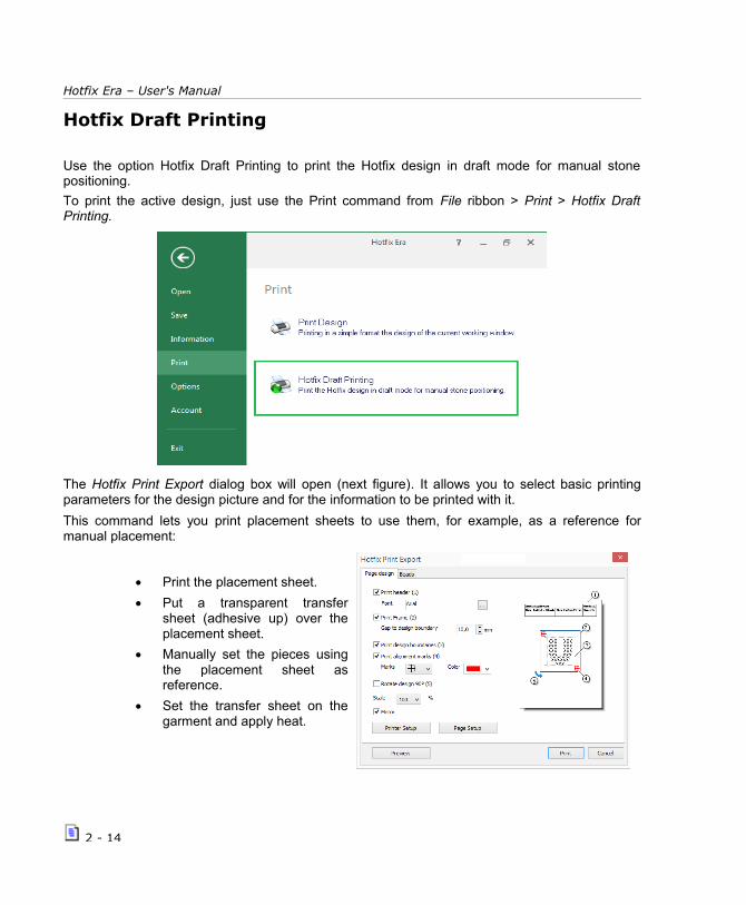
Hotfix Draft Printing
Use the option Hotfix Draft Printing to print the Hotfix design in draft mode for manual stonepositioning.
To print the active design, just use the Print command from File ribbon > Print > Hotfix DraftPrinting.
The Hotfix Print Export dialog box will open (next figure). It allows you to select basic printingparameters for the design picture and for the information to be printed with it.
This command lets you print placement sheets to use them, for example, as a reference formanual placement:
Print the placement sheet.
Put a transparent transfersheet (adhesive up) over theplacement sheet.
Manually set the pieces usingthe placement sheet asreference.
Set the transfer sheet on thegarment and apply heat.
2 - 14

The File Page and Ribbons
The print dialog is organized in two tabs:
Page design:
Lets you control the reference elements that
will be printed: information header, designframe, alignment marks, design rotation andgeneral scale.
Beads:
Includes two lists: A bead types list at the leftand a Pages List at the right. You can changethe Marks visualization and colors among theoptions given, to be able to locate them easier.
2 - 15

Hotfix Era – User's Manual
File – Options
Hotfix Era lets you customize many topics related with the interface look and system behaviour.All the configurable options are managed from the FILE tab, OPTIONS section.
These options include functions related with the setting of this software application.
Options and Preferences show threepossible customization choices:
Preferences Setup. You canmake some adjustments onthe program to suit yourneeds.
Customize Shortcuts. Youcan modify some of thepredefined function keys towork faster on your designs.
Preferences Setup
The Options and Preferences boxshows a tree where the configurableoptions are organized in categoriesand topics.
Your settings will be saved when youpress the OK button and will bepreserved permanently.
The following paragraphs contain abrief description about theconfigurable options:
2 - 16

The File Page and Ribbons
Application
This category contains settings to set the preferences about:
1. Live Update: When enabled, the system checks for updates, services packs, newsand special offers available for your product. This option requires internet access.
2. System language
3. Skin name: you have a list of available skins to choose from, to change the appearance of your software.
4. Users Resources path: to set the location of the components made by the user.
Project
General: This category containsoptions to control how the systemstarts.
Units: Lets you select themeasurement units used for differentelements. Click the numbers in theGroup column and review the briefdescription, indicating the elementsthe units apply to.
Hotfix: This category allows you toconfigure what kind of beads will beshown (Rhinestones / Rhinestuds /Nailheads / Sequins / Spangles), thecutting margin and the way of sortingthem.
Workspace
Within this category you will find options to manage the appearance of the workspace andvisual aids, and the behaviour of some visual tools.
General: Options for rulers, large cross cursor and ribbon fitting in 1024 pixels wide screens
Limits: Set the max. workspace size and decide if the work area is limited to the workspace(system will not allow you to place objects outside the workspace if you check the option)
Visual Aids: This group lets you control de Guidelines (or Reference lines) position and colourand to define the Grid and Sub grid look and behaviour
Object References and Marks: Controls in this group allow you to define the visual aspect(color, transparence, etc.) of the marks the system uses to represent nodes, sections
2 - 17

Hotfix Era – User's Manual
references, etc.
Zoom: Use these controls to define the zoom factors and use of mouse wheel for zooming.
Auto scroll: This group controls the automatic scrolling feature: region size, speed, etc.
Video card Settings: These are important settings related with the performance of your displaysystem. If you are using a good video card, you will want to set the Video hardware accelerationto the highest value to get faster screen redraws. It is also recommended to activate theEnhanced line drawing.
Some video cards may be not fully compatible with OpenGL implementation, and you might experience abnormal screenredraw. Lower the Video hardware acceleration value. Set value to zero, if video card is totally incompatible with OpenGL.
Create and Edit
This category includes the available customizable options for edition and creation tools and to setsome general features of stitch generation and processing.
General: You will find options to control curve types (bezier or arcs), to hide and show somereferences while create or edit, to manage the Auto Generation mechanism, etc.
Snaps: Use this controls to enable or disable the snap schema and to define what snap tools youwant. Snap is useful when you need to digitize with large accuracy, for example, when creatinggeometric designs.
Notifications
Into this category you will find options to configure sounds for specific events and to control theMessages Window behaviour.
Reset to Default Values
Settings in each group can be reset to their default values by pressing the Default Setting buttonlocated on the corresponding group. If you need to reset all the configurable options to theirfactory values, use the button Reset All To Default located below the tree panel.
2 - 18

The File Page and Ribbons
Customizing Shortcuts
Hotfix Era lets you customize the shortcuts for most of the commands. To do so, follow the nextsteps:
1- Click on the FILE tab, then on OPTIONS group and select “Customize Shortcuts”.
2- In the Shortcuts box, locate the command you want to modify its shortcut, using the Categoryand Command lists.
3- Click on the box named Shortcut, press the desired key sequence and confirm it with thegreen button. Repeat these steps for all commands you need.
2 - 19

Hotfix Era – User's Manual
Keyboard Shortcuts
2 - 20

The File Page and Ribbons
File – Account
Gives you information aboutthe User, installed Product,Activation Status.
It also lets you buy Featuresand Components.
You have contact links tothe Service Center;Technical Assistance; SalesContact; and to changeRegistered User andLicense Ownership.
Learning about the different RibbonsOnce you have selected any of the File-Open commands, the main view will appear.
You will see a group of different ribbons which we named in the previous chapter. In this chapter we will talk about the Home and View ribbons. Artwork ribbon will be studied in chapter 3 Images and Vectors. Hotfix ribbon will be shown from chapters 4 to 7.
Within Hotfix Era we call Main View to a series ofpanels and windows that display the designconsidering different aspects, like graphic look,entities sequence, stitches, etc.
Most of the job with a design is done in the graphicarea we call workspace or main view.
It is the largest area in your screen and displays thedesign graphically. Every time you open a designor create a new one, is is presented within a newtab. You can switch among loaded designs bysimply clicking on its corresponding tab.
2 - 21

Hotfix Era – User's Manual
The Home ribbon
Open
This group has two commands: New and Open.
New: click on the arrow to unfold the possible options.
Simple Wizard: Use this option to create newdesigns by indicating just the material and hoop.
Hotfix Wizard: Same as previous one.
Open: click on the arrow to unfold the possible options.
Open Design: Use this option to open a native.
Open a Hotfix Machine File: Allows opening a filewith extension YNG; DST; PLT and CSV.
Open an Stencil File: Allows opening a file withextension PLT.
2 - 22

The File Page and Ribbons
Catalogs
It is located on the HOME ribbon, INSERT group. It is afloating window which remains open once you click on itsaccess.
It allows graphic browsing of all the media handled by yoursoftware so you have quick access to it. It´s divided in threepanels. The upper one shows the media type: Images(Raster and Vectors); Native Designs (DSG files); HotfixDesigns (machine format) and Motifs (predefined files readyto be used);
Having selected the media type, the second panel, named“Folders” shows the available folders on your computer.Navigate through your disk units and folders until you find theone needed. The third panel, named “Images”, will displaythe contents of the selected folder graphically.
Once you find the desired object, step on it, and drag it into the workspace. The system willrecognize the type of object, proceed to open it on the workspace, and visualize thecorresponding ribbon toolbars.
Example: We are going to open a hotfix motif named HRT-A0001. Follow these steps:
1) Open a blank document. On the Home ribbon, Insert group, click on Catalogs.
2)
On the first panel, click on the to the right of the item Media: Images - Raster to unfold the list of other Media type available.
Click on Motifs – Hotfix
2 - 23

Hotfix Era – User's Manual
3) The Media type will now show: Motifs – Hotfix
The third panel will show Motifs and beneath it you willsee all the Motifs found on the first Category (listed inCategories).
To see the contents of another Category, on the
second panel, click on the to the right of the itemCategories to unfold the list of the others available.Click on the desired one to show the contents on thethird panel.
4)
Step on the motif you want. In this case, the HRT-A001.
You have two options: OPEN or EDIT the motif.
5a) OPEN it as a new design...
> just by dragging it from the Catalogs window anddropping it on the workspace;
> double click on it on the Catalogs window, and then,on the workspace, keeping the left mouse buttondepressed, move it as you were making a rectangle.You will see the design being made. When you aresatisfied with the size, release the button.
Note: See that the name of the document tab saysDesign4, which corresponds to a design file.
5b) EDIT the motif to make changes on it.
When you save it, it will update the existing motif.
Create a different one by using the Save as...command.
Note: See that the name of the document tab saysHRT-A001, which corresponds to a motif file beingedited.
2 - 24

The File Page and Ribbons
Undo and redo
It is always possible to undo the last actions taken, starting by the most recent,from the Undo command.
It is also possible to access this command from the quick access toolbar or from the Ctrl + Zshortcut. If you are not pleased with the undo result, you can restate the option from the commandRedo, or through the shortcut Ctrl + Y.
Note: Remember that in basic levels, there's a limited number of undo/redo actions.
Clipboard
During the process of making copy and paste, once you have pressedCTRL+C, the object will remain in the clipboard until you decide to pastethe content of it (CTRL+V). You can copy and paste raster and vectorimages; design, embroidery, and hotfix objects from the clipboard.
Delete
Use this command to delete a section or group of sections without modifying the rest of the design. First of all, it is necessary to select a section or block. Then, access the Homeribbon or context menu and click on the Delete button.
Cut
This command copies the section or block selected into the clipboard and deletes it fromthe current document without modifying the rest of the design. The block cut remains inthe clipboard. Activate the command from the Home ribbon or click on Ctrl + X.
Copy
This command copies the section or block into the clipboard, without altering the currentdesign or deleting the original section or block. Click on the Copy command from theHome ribbon or click on Ctrl + C so that the clipboard holds the selected block. Then,paste it wherever you want.
2 - 25
Hotfix Era – User's Manual
Paste
This command copies the clipboard content in the active document. To use thiscommand, you must have previously copied or cut a block. Click on the Paste command.Paste in the toolbar or press the Ctrl + V keys.
Paste in Place
This command copies the clipboard content in the active document, but exactly in thesame place of the copied object (original).
Yet, there are certain image creation applications that allow you to copy an image file type you areworking on (Windows Metafile, EMF, etc.), to the Clipboard. This is recommended for certainsketches with a high level of elements, or when it is necessary to obtain more precision (betterlevel of detail). You may then paste it in Embroidery Office using these commands.
Format
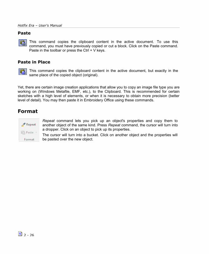
Repeat command lets you pick up an object's properties and copy them toanother object of the same kind. Press Repeat command, the cursor will turn intoa dropper. Click on an object to pick up its properties.
The cursor will turn into a bucket. Click on another object and the properties willbe pasted over the new object.
2 - 26

The File Page and Ribbons
Work Area (Pages and Hoops)
Pages allows defining the work area as a printer/cutter sheet type (A4, Letter,etc.).
Click on the arrow to the left of the Pages button to unfoldthe available options.
You can also make a new one with your own dimensionson “Page Settings”.
Hoops allows you to display in the workspace an schematic representation of thehoop you will use at the time to process your design.
Displaying the hoop on screen gives you the chance to check if design will fit in the hoop area safely, avoiding any machine incidents, and to fix its position if required.
Click on the arrow to the left of the Hoops button to unfoldthe available options.
From Hotfix – Machine Workspace, you can select one of the available ones.
From the Hotfix Hoops Database, you can customize yourhoops. Add a new one or delete an existing one.
2 - 27

Hotfix Era – User's Manual
Once selected press OK and use the Show Hoop command located in the Home ribbon > Work Area group > Hoops button, to turn the hoop on/off.
Creating new hoops
If the one you need is not among the ones available, go to Hotfix Hoops Database, and create one on your own.
Use the Add command (the button with a + sign located above the list at the left) to add a newhoop. You will need to specify a name, brand and code (it will help to keep your hoopdatabase well organized) and, of course, the basic shape and size.
You can also specify a safety margin, that will be displayed as a dotted line around the hoop,and will prevent you to place stitches too closer to the hoop edge. Even more, if you ownseveral machines, you may add a reference to later help you identify what machines can usethe hoop, by filling the list “Compatible with”.
2 - 28

The File Page and Ribbons
Output options
These options allow you to quickly access the commands thatare necessary for gathering information on the design you aremaking; saving and printing it; and sharing it by e-mail orthrough the social networks.
Gives important information about the design. Alreadymentioned in this chapter, Page 7.
2 - 29

Hotfix Era – User's Manual
Save File: Save the Design Document (DSG files).
Save as...: Save a copy of the working window with anothername.
Save Motif: Create a motif (*.motif file) out of a design youcreated. You can also use a block of sections instead of thewhole design. Use the motif from the Catalog (page 32).
Allows you to print your design in a standard way or withdifferent styles. Already mentioned in this chapter, Page 19.
This option allows you to upload the design that is on the workwindow to the Social Networks - Twitter. Already mentioned inthis chapter, page 9.
System options
System Settings gives a quick access to the Preferences a Setup window. Theother way is from File Page > Options group > Preferences and Setup
The View ribbonThe View ribbon contains all the commands needed to control how your designs will be displayedon screen. It gives access to the basic Zoom tools, visualization mode (Normal – 3D), lets you
2 - 30
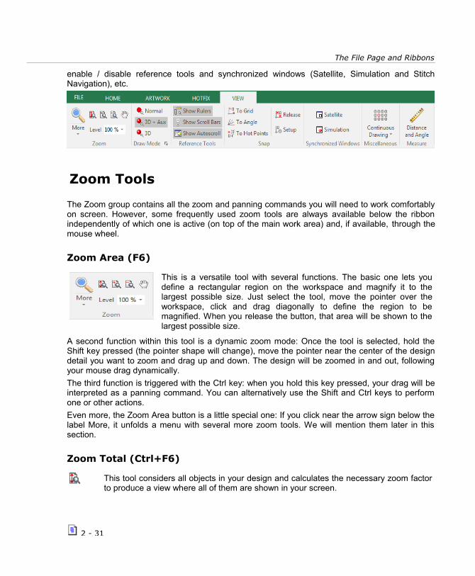
The File Page and Ribbons
enable / disable reference tools and synchronized windows (Satellite, Simulation and StitchNavigation), etc.
Zoom Tools
The Zoom group contains all the zoom and panning commands you will need to work comfortablyon screen. However, some frequently used zoom tools are always available below the ribbonindependently of which one is active (on top of the main work area) and, if available, through themouse wheel.
Zoom Area (F6)
This is a versatile tool with several functions. The basic one lets youdefine a rectangular region on the workspace and magnify it to thelargest possible size. Just select the tool, move the pointer over theworkspace, click and drag diagonally to define the region to bemagnified. When you release the button, that area will be shown to thelargest possible size.
A second function within this tool is a dynamic zoom mode: Once the tool is selected, hold theShift key pressed (the pointer shape will change), move the pointer near the center of the designdetail you want to zoom and drag up and down. The design will be zoomed in and out, followingyour mouse drag dynamically.
The third function is triggered with the Ctrl key: when you hold this key pressed, your drag will beinterpreted as a panning command. You can alternatively use the Shift and Ctrl keys to performone or other actions.
Even more, the Zoom Area button is a little special one: If you click near the arrow sign below thelabel More, it unfolds a menu with several more zoom tools. We will mention them later in thissection.
Zoom Total (Ctrl+F6)
This tool considers all objects in your design and calculates the necessary zoom factorto produce a view where all of them are shown in your screen.
2 - 31

Hotfix Era – User's Manual
Pan
Pan is the action of moving the viewable area so different regions of the design appearon the screen. The result is similar to what you get when using the scroll bars. Notethat the physical design position does not change at all, just the region you are viewingchanges.
To use the Pan command, you have two different ways:
a) Select it from the auxiliar toolbar, move the pointer over the workspace and drag.The tool will not remain active when you release the mouse button;
b) From Reference Tools, click on Show Rulers. Now place the cursor over the ruler, itwill change from an arrow to a hand. Click and move the mouse. You will see that theworkspace and ruler move in the direction you move the mouse.
Zoom In – Zoom out
Zoom In (+) allows a more detailed (closer) view of the design, while Zoom Out (-)produces a less detailed view, (more distant)
Both tools work with a predefined factor you can set through File – Options -Preferences Setup – Workspace – Zoom.
Zoom in-out using the mouse wheel
If your mouse has a center wheel, you can use it to zoom in and out. Just move thepointer to the region you want to keep visible and rotate the wheel clockwise orcounterclockwise.
Zoom Scale
This control allows you to set the main view to a given predefined scale. Please, notethat you need to calibrate your screen to get accurate results. See Calibrate Rulers,later on, in this chapter.
2 - 32
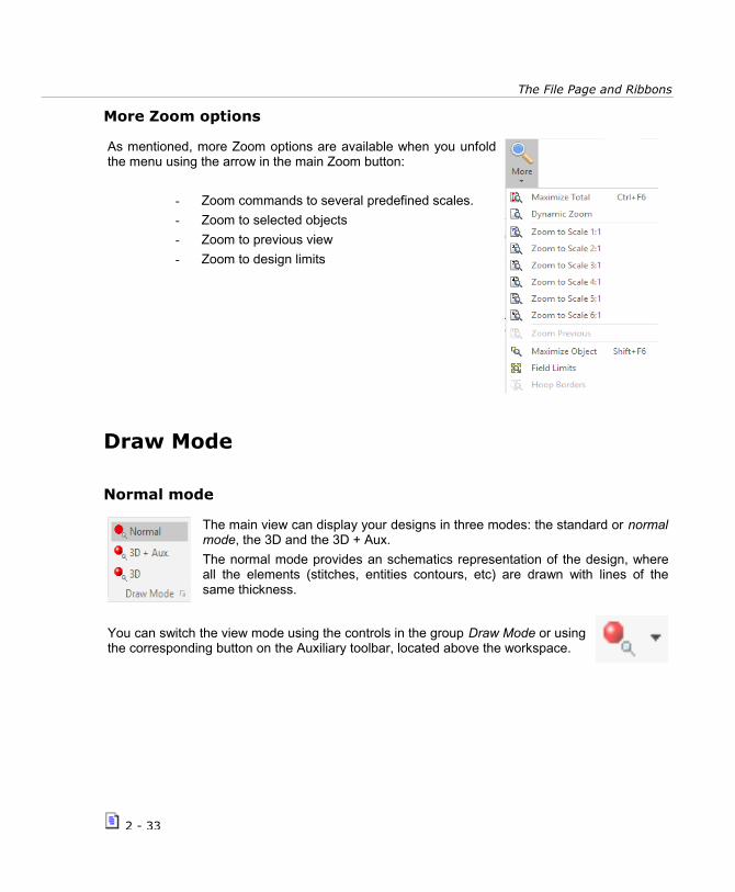
The File Page and Ribbons
More Zoom options
As mentioned, more Zoom options are available when you unfoldthe menu using the arrow in the main Zoom button:
- Zoom commands to several predefined scales.
- Zoom to selected objects
- Zoom to previous view
- Zoom to design limits
Draw Mode
Normal mode
The main view can display your designs in three modes: the standard or normalmode, the 3D and the 3D + Aux.
The normal mode provides an schematics representation of the design, whereall the elements (stitches, entities contours, etc) are drawn with lines of thesame thickness.
You can switch the view mode using the controls in the group Draw Mode or usingthe corresponding button on the Auxiliary toolbar, located above the workspace.
2 - 33

Hotfix Era – User's Manual
3D mode
It is a 3D piece simulated mode, where the design isdisplayed in a very realistic representation, that provides agood feedback about what its final appearance will be.
3D mode can be tuned to match your preferences and toget the most realistic view possible. Click on the arrow onthe lower right corner to display 3D Light and Qualitysettings.
A small box will display, with controls to set light direction(drag the small mark in the edge of the shaded circle),contrast and simulation quality (more quality means lowerdisplay speed, but modern video hardware allows you towork comfortably even at top quality).
3D + Aux. mode
It is the same as the 3D piece simulated mode, but it also shows the image usedas reference for designing. Shortcut for this function (F7).
2 - 34
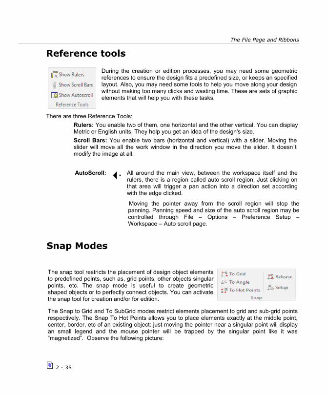
The File Page and Ribbons
Reference tools
During the creation or edition processes, you may need some geometricreferences to ensure the design fits a predefined size, or keeps an specifiedlayout. Also, you may need some tools to help you move along your designwithout making too many clicks and wasting time. These are sets of graphicelements that will help you with these tasks.
There are three Reference Tools:
Rulers: You enable two of them, one horizontal and the other vertical. You can display Metric or English units. They help you get an idea of the design's size.
Scroll Bars: You enable two bars (horizontal and vertical) with a slider. Moving the slider will move all the work window in the direction you move the slider. It doesn´t modify the image at all.
AutoScroll: All around the main view, between the workspace itself and therulers, there is a region called auto scroll region. Just clicking onthat area will trigger a pan action into a direction set accordingwith the edge clicked.
Moving the pointer away from the scroll region will stop thepanning. Panning speed and size of the auto scroll region may becontrolled through File – Options – Preference Setup –Workspace – Auto scroll page.
Snap Modes
The snap tool restricts the placement of design object elementsto predefined points, such as, grid points, other objects singularpoints, etc. The snap mode is useful to create geometricshaped objects or to perfectly connect objects. You can activatethe snap tool for creation and/or for edition.
The Snap to Grid and To SubGrid modes restrict elements placement to grid and sub-grid pointsrespectively. The Snap To Hot Points allows you to place elements exactly at the middle point,center, border, etc of an existing object: just moving the pointer near a singular point will displayan small legend and the mouse pointer will be trapped by the singular point like it was“magnetized”. Observe the following picture:
2 - 35
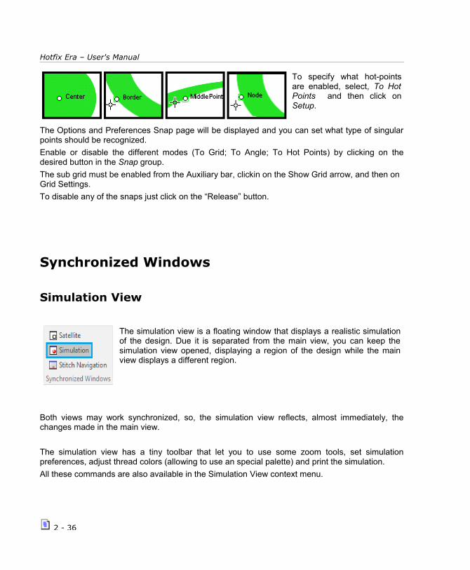
Hotfix Era – User's Manual
To specify what hot-pointsare enabled, select, To HotPoints and then click onSetup.
The Options and Preferences Snap page will be displayed and you can set what type of singularpoints should be recognized.
Enable or disable the different modes (To Grid; To Angle; To Hot Points) by clicking on thedesired button in the Snap group.
The sub grid must be enabled from the Auxiliary bar, clickin on the Show Grid arrow, and then on Grid Settings.
To disable any of the snaps just click on the “Release” button.
Synchronized Windows
Simulation View
The simulation view is a floating window that displays a realistic simulationof the design. Due it is separated from the main view, you can keep thesimulation view opened, displaying a region of the design while the mainview displays a different region.
Both views may work synchronized, so, the simulation view reflects, almost immediately, thechanges made in the main view.
The simulation view has a tiny toolbar that let you to use some zoom tools, set simulationpreferences, adjust thread colors (allowing to use an special palette) and print the simulation.
All these commands are also available in the Simulation View context menu.
2 - 36

The File Page and Ribbons
Satellite View
This floating window provides, all the time, a complete view of thedesign and adds a graphical reference to give you feedback about theregion currently displayed in the workspace. The examples below showthe workspace with the Satellite opened in two different situations. Notethe small rectangle inside the Satellite view, indicating the region of thedesign currently displayed in the workspace.
Satellite view is synchronized with the Main view: if you change the zoom level or pan the Mainview, Satellite will be refreshed properly. You can also pan and zoom from the Satellite view:dragging the rectangle (start drag from its interior) will produce a pan action in the Main view and,dragging the rectangle edges, will produce a zoom action in the Main view.
2 - 37

Hotfix Era – User's Manual
Miscellaneous
This button allows you to set the options for visualizing how a design incontinuous working mode would be like without the need to take it to themachine to test it.
Click on the arrow button to unfold the options menu.
Enables/disables the visualization of the continuous drawing of thedesign.
Allows you to configure the horizontal and vertical spacing of theobjects.
Move the slider to modify the transparency of all the objects except forthe original one.
You can make a visual repetition ot your design on both horizontal and vertical axis.
The idea of this tool is to give a very real result of how your design is going to be, with no need oftaking it to the machine to test it and adjust parameters.
You can set up the distance between designs for both axis.
Modify the parameters until you are satisfied with the results. Remember to write down the valuesused for that particular design.
2 - 38
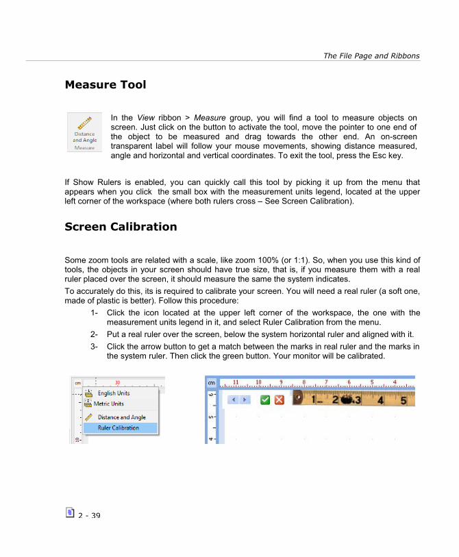
The File Page and Ribbons
Measure Tool
In the View ribbon > Measure group, you will find a tool to measure objects onscreen. Just click on the button to activate the tool, move the pointer to one end ofthe object to be measured and drag towards the other end. An on-screentransparent label will follow your mouse movements, showing distance measured,angle and horizontal and vertical coordinates. To exit the tool, press the Esc key.
If Show Rulers is enabled, you can quickly call this tool by picking it up from the menu thatappears when you click the small box with the measurement units legend, located at the upperleft corner of the workspace (where both rulers cross – See Screen Calibration).
Screen Calibration
Some zoom tools are related with a scale, like zoom 100% (or 1:1). So, when you use this kind oftools, the objects in your screen should have true size, that is, if you measure them with a realruler placed over the screen, it should measure the same the system indicates.
To accurately do this, its is required to calibrate your screen. You will need a real ruler (a soft one,made of plastic is better). Follow this procedure:
1- Click the icon located at the upper left corner of the workspace, the one with themeasurement units legend in it, and select Ruler Calibration from the menu.
2- Put a real ruler over the screen, below the system horizontal ruler and aligned with it.
3- Click the arrow button to get a match between the marks in real ruler and the marks inthe system ruler. Then click the green button. Your monitor will be calibrated.
2 - 39

Hotfix Era – User's Manual
Auxiliary Toolbar
Below the ribbon bar and on top of the workspace you will find this bar, where you have someuseful functions handy like Create Sections; Select Objects; Smart Design; Zoom tools; andsome visual aids like guidelines, grid and subgrid; object guides and hide/show commands (firstfigure). On the right side of this bar there are some “traffic lights” to show/hide/block differentobject layers (Auxiliar; Screen Printing; Cutter; Hotfix) (second figure).
Create Sections
This button gathers all the tools that are available for creating a hotfix design(depending on your system level). Click on the arrow to unfold the list of tools.The creation tools are explained in Chapter 4.
Select Object
This tool allows you to select an object or block of objects, which can be rasterimages, vectors, or hotfix objects. Then you can make modifications on thegeometry (expand, reduce, rotate, mirror, etc.).
A large set of selection tools is available from the Select Object menu, to beable to create your blocks.
Smart Design
This working mode accelerates the activities related with the objects creationand edition, as well as some functions related with auto-digitizing (auto-complete).
The Smart Design tool includes the different types of objects with theirrespective fill modes. It will be explained in Chapter 7.
Other visualization tools.
2 - 40

The File Page and Ribbons
These were explained in Zoom Tools, page 31 in this chapter.
Grid
The Grid command controls the visibility of a set of small, equally spaced marks onthe workspace. These marks allows you to accurately place objects within yourdesign. You can control many aspects of the grid, such as the distance, markshape, color, etc. Use the Grid button to turn on/off grid visibility.
Grid setupGrid customization controls are displayed when you click on the arrowbutton. Show grid lets you hide/show the grid. A basic and interactivesize setting is available with the command Setup Grid and a detailedconfiguration is accomplished through the Grid Settings...
Setup Grid: Turn on the grid and then select Setup Grid. The mouse pointer will changeinto a ruler shaped one, and when you drag, the grid size will change following yourmouse movements. This method is useful when you need to set the grid distancematching the size of an object displayed in the screen, such as a detail in an image.
Grid Settings...: This command pops up the Options box, with the grid page selected.You will find controls to set the grid position (grid displayed above or below the objects),style, color and size. You can also set a sub-grid, allowing a set of closer sub-marks bedisplayed inside the main grid marks.
Guidelines
We call Guidelines to a set of auxiliary vertical and/or horizontal lines you can set tohelp with object alignment and placement.
To add a Guideline, use the following procedure:
2 - 41

Hotfix Era – User's Manual
1) Move the mouse pointer overone of the rulers (vertical orhorizontal)
2) While keeping the Ctrl keydepressed, press the mouseleft button and drag towardsthe workspace. A guideline willappear and follow the mousepointer while you drag.
3) Once the pointer reaches theposition you want, release the mouse button.
Repeat the operation for each guideline you want to add.
If you need to change a guideline position, just move the pointer over thecorresponding icon located over the ruler, and drag it.
Using the mouse right button over the guideline icon, opens acontext menu with a group of commands. You may remove oneor all guidelines, set a guideline as default and change theguidelines color.
Guide setup
Guide customization controls are displayed when you click on thearrow button. Show guide objects lets you hide/show the guidelines.
Using the Guide Setup – Delete All Guide Objects, you can quicklyremove all the guidelines.
Having the Guidelines enabled, the command Guide Setup – Guideobjects Options... pops up the Guidelines Editor window.
2 - 42

The File Page and Ribbons
From this window, you can achieve a precise location of the guidelines youmade. To modify a guideline, just click on it to select it, change the coordinateand press Apply.
Also you can add new guidelines from the Add button. Select the type youwant, insert the coordinates, choose a color and press Apply. The newguideline will appear on the screen.
Apart from the common ones, Horizontal and Vertical lines, you will find three new kind ofguides: Free Line, where you can make a segment guideline with the direction you want; andtwo guide objects, Square/Rectangle and Circle/Ellipse in which you can have a shape madeout of segment guidelines.
To delete a guideline, click on it to select it, and click on Delete.
You can also save your current guideline disposition as a template for a later use.
Show/Hide design references
We call Design References to a set of graphic elements that improve designvisualization. This set contains the controls required to turn on/off theseelements.
Solid Vector : Shows the solid (complete) vector or just the outline of it.
Show Sections: Show/Hide entities wireframe. Sometimes, specially during the finishingtasks, is usefull to view just the stitches, hiding all other references.
Show Connectors: Show/Hide thread connections between entities.
2 - 43

Hotfix Era – User's Manual
Show Commands: Show/Hide graphic indicators for machine functions or machinecontrols such as, color change, thread trims, etc.
Show Design Start/End: Show/Hide special screen symbols to indicate designs startand end points.
Show Hotfix: Turn on/off beads display in realistic 3D view.
Show Solid Hotfix: Turn on/off beads display in plain colors.
Traffic Lights
These coloured led buttons allow you to show, hide, or block different object layers (Auxiliar;Screen Printing; Cutter; Hotfix).
Auxiliar
Allows control over Images used as reference for design creation.
Click on the Auxiliar button to toggle between Hide and Show image.When image is shown, led will be green; when image is hidden, led willbe red.
Click on the arrow to visualize the other available options:
Turns off all reference images. To turn them on, just click over theauxiliar button again. Light will change from red to green.
Locks all reference images. This means that you cannot select them.Very useful when you are digitizing and do not want to move the imageor select it by mistake. To unlock them, just click over the auxiliarbutton again. Light will change from yellow to green.
If you have vector images, and/or hotfix objects on screen and youwant to leave only the auxiliar images visible. Auxiliar led will be greenand all the others will be red.
If you have vector images, and/or hotfix objects on screen and youwant to lock them, to be able to work on the auxiliar images only.Auxiliar led will be green and all the others will be yellow.
When you enable the onscreen simulation (3D), the Auxiliary images will become hidden. To view
2 - 44
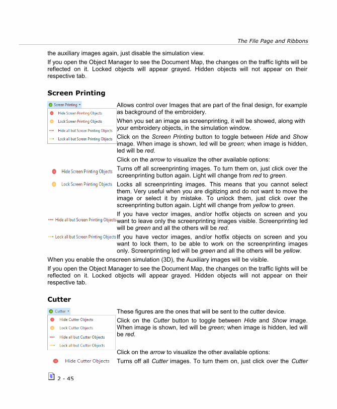
The File Page and Ribbons
the auxiliary images again, just disable the simulation view.
If you open the Object Manager to see the Document Map, the changes on the traffic lights will bereflected on it. Locked objects will appear grayed. Hidden objects will not appear on theirrespective tab.
Screen Printing
Allows control over Images that are part of the final design, for exampleas background of the embroidery.
When you set an image as screenprinting, it will be showed, along with your embroidery objects, in the simulation window.
Click on the Screen Printing button to toggle between Hide and Showimage. When image is shown, led will be green; when image is hidden,led will be red.
Click on the arrow to visualize the other available options:
Turns off all screenprinting images. To turn them on, just click over thescreenprinting button again. Light will change from red to green.
Locks all screenprinting images. This means that you cannot selectthem. Very useful when you are digitizing and do not want to move theimage or select it by mistake. To unlock them, just click over thescreenprinting button again. Light will change from yellow to green.
If you have vector images, and/or hotfix objects on screen and youwant to leave only the screenprinting images visible. Screenprinting ledwill be green and all the others will be red.
If you have vector images, and/or hotfix objects on screen and youwant to lock them, to be able to work on the screenprinting imagesonly. Screenprinting led will be green and all the others will be yellow.
When you enable the onscreen simulation (3D), the Auxiliary images will be visible.
If you open the Object Manager to see the Document Map, the changes on the traffic lights will bereflected on it. Locked objects will appear grayed. Hidden objects will not appear on theirrespective tab.
Cutter
These figures are the ones that will be sent to the cutter device.
Click on the Cutter button to toggle between Hide and Show image.When image is shown, led will be green; when image is hidden, led willbe red.
Click on the arrow to visualize the other available options:
Turns off all Cutter images. To turn them on, just click over the Cutter
2 - 45

Hotfix Era – User's Manual
button again. Light will change from red to green.
Locks all Cutter images. This means that you cannot select them. Veryuseful when you are digitizing and do not want to move the image orselect it by mistake. To unlock them, just click over the Cutter buttonagain. Light will change from yellow to green.
If you have vector images, and/or hotfix objects on screen and youwant to leave only the Cutter images visible. Cutter led will be greenand all the others will be red.
If you have vector images, and/or hotfix objects on screen and youwant to lock them, to be able to work on the Cutter images only. Cutterled will be green and all the others will be yellow.
When you enable the onscreen simulation (3D), the Cutter images will be visible.
If you open the Object Manager to see the Document Map, the changes on the traffic lights will bereflected on it. Locked objects will appear grayed. Hidden objects will not appear on theirrespective tab.
Hotfix
Allows control over the hotfix design objects.
Click on the Hotfix button to toggle between Hide and Showembroidery. When Hotfix is shown, led will be green; when Hotfix ishidden, led will be red.
Click on the arrow to visualize the other available options:
Turns off all Hotfix objects. To turn them on, just click over the Hotfixbutton again. Light will change from red to green.
Locks all Hotfix objects. This means that you cannot select them. Veryuseful when you are working on an image or hotfix object and do notwant to move a Hotfix object or select it by mistake. To unlock them,just click over the Hotfix button again. Light will change from yellow togreen.
If you have raster and vector images, and/or hotfix objects on screenand you want to leave only the Hotfix objects visible. Hotfix led will begreen and all the others will be red.
If you have raster and vector images, and/or hotfix objects on screenand you want to lock them, to be able to work on the Hotfix objectsonly. Hotfix led will be green and all the others will be yellow.
If you open the Object Manager to see the Document Map, the changes on the traffic lights will bereflected on it. Locked objects will appear grayed. Hidden objects will not appear on theirrespective tab.
2 - 46

The File Page and Ribbons
Hotfix pieces libraryThe vertical toolbar that appears at the left of the working area displays a collection of hotfixbeads you can easily pick to create your hotfix objects. This collection, that also appears asgalleries within the hotfix objects ribbon, and that is quite similar to a color palette, is called Hot fixPalette or Bead Bar.
Hotfix Palette or Bead Bar.
To choose what hotfix pieces you’ll see in the bead bar, you need to use a large set of hotfixpieces called Hotfix Catalog. Using the catalog you can define and change the bead bar, createnew ones and save and open them from disk. So, the Hotfix Catalog is also the management toolfor bead bars.
Clicking the Hotfix Catalog button in the vertical toolbar opens the catalog window.Inside it, there are two main panels: the bead bar at the left and the library at the right
The main idea behind this box is that you build your bead palette, or bead bar by selecting thepieces you want to use from the beads library. The following paragraphs explain how to do thatand also describe the panels and related tools in depth.
Beads Library
The Beads Library is a collection of thousands of hotfix pieces organized by type that you caneasily browse to choose the pieces you’ll use in your design.
There are a group of tabs located at the top of the right panel to let you access the catalog bybead type: rhinestones, rhinestuds, nailheads, etc.
Just activate the tab corresponding to the type you want to browse and then click on one of thelisted shapes. The available Sizes and pieces will be shown underneath. Use the Controls to addthe desired beads to your bead bar. They are explained next.
2 - 47

Hotfix Era – User's Manual
Available Controls:
Between the two main panels you will find several icons: a yellow star, and some colored pointingarrows. Each one has a different purpose.
Star icon: Stepping on a piece, and clicking on this icon will place a little yellow star on theupper left margin of the selected bead and will add it to the Favorites tab. You can have allyou most used beads on the favorites tab for a quicker selection. Click over the star icon tounmark the piece and delete it from the favorites tab.
Add / Replace / Remove from bead bar: A group of arrow icons allow you easily add, replaceand remove pieces from the bead bar.
When you step on a piece on the right panel, if a green left pointing arrow appears, itmeans that it is not currently included in the bead bar (on the left panel) and you can simplyclick on the arrow to add it. Instead, if a red right pointing arrow appears, it means that it isalready included in the bead bar and clicking on the arrow will remove it from the bead bar.You can also double click on a bead to remove it from the bead bar. To replace an existingbead by the one you want, highlight a bed on the bead bar, and press the orange leftpointing arrow icon.
Bead barThis panel is just a more detailed view of the bead palette displayed at the left of the workingarea. It’s an ordered list of hotfix pieces, you can freely arrange by reordering, adding andremoving elements. The list must have at least one element and may have as many elements asyou need.
Changing order: To arrange the order of the pieces, just click on one and use the up and downarrows until you locate it in the desired position. You can also use the context menu to move apiece up or down into the list, one position at a time.
Removing pieces: Step on the item you want to remove to highlight it and click on the red rightpointing arrow, or double click on it.
Adding pieces: Simply, pick the piece you want to add from the library, drag it into the list anddrop it at the desired position. You’ll see blue horizontal marks appearing and disappearingbetween the items; they are indicating the position the piece will take if you drop it in that moment.
Be careful when you drop because dropping between items will add pieces while dropping overan item will replace the piece.
Replacing pieces: If you need to replace a piece for a different one you may proceed to removeit and then to add the new one or you may take a shortcut: pick the new piece from the library,drag it into the list and drop it over the piece you want to replace.
Clearing the bead bar: By default, the system shows a predefined bead bar to let you startworking. However, you may want to create an entire new one, starting from zero.
This tool, located at the bottom left side of the catalog window, clears the entire bead bar,producing an empty, fresh list.
2 - 48

The File Page and Ribbons
Save the bead bar: Once you create your own bead bar, or modify an existing one, you cansave it to disk for permanent storage.
To do it, click the Save command and in the save dialog box, enter a name for your bead barand click OK.
Load a bead bar from disk: Previously saved bead bars may be loaded using the Opencommand. When you activate the command, the system displays a list with the names of allpreviously saved bead bars. Just select the one you want to load and click OK.
Deleting a bead bar from disk: Use this command to permanently delete saved bead bars.Just activate the command, select the bead bar you want to delete from the displayed listand click OK.
Set as Default: The current bead bar may, that is, the one currently displayed in the leftpanel, may be set as the default bead bar. This means that every time you create a newdesign, that bead bar will be automatically loaded and displayed in the vertical toolbar.
Quick Hotfix Selection tool
Click on the arrow to the right of the Bead Bar icon to openthe Quick Hotfix selection tool. It contains useful commandsto quickly manage your bead bar.
Open Hotfix catalog: to let you configure your bead bar.
If you replace any of the beads, all objects that were using the replaced bead will be recalculatedwith the new bead.
Delete unused beads: Checks used beads in your design and deletes the unused ones from thebead bar.
Add bead: Lets you select a bead that will be added to the current bead bar. It opens the HotfixSelector window.
2 - 49
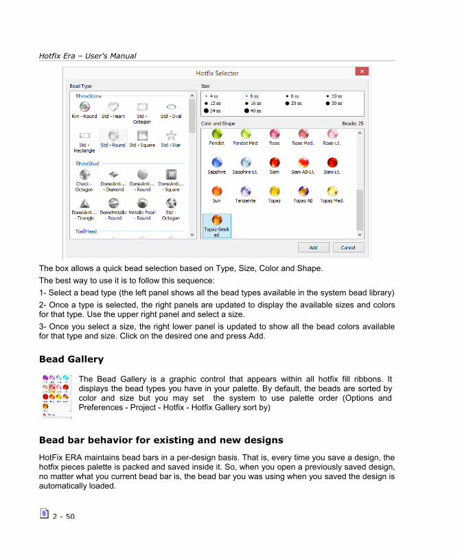
Hotfix Era – User's Manual
The box allows a quick bead selection based on Type, Size, Color and Shape.
The best way to use it is to follow this sequence:
1- Select a bead type (the left panel shows all the bead types available in the system bead library)
2- Once a type is selected, the right panels are updated to display the available sizes and colorsfor that type. Use the upper right panel and select a size.
3- Once you select a size, the right lower panel is updated to show all the bead colors availablefor that type and size. Click on the desired one and press Add.
Bead Gallery
The Bead Gallery is a graphic control that appears within all hotfix fill ribbons. Itdisplays the bead types you have in your palette. By default, the beads are sorted bycolor and size but you may set the system to use palette order (Options andPreferences - Project - Hotfix - Hotfix Gallery sort by)
Bead bar behavior for existing and new designs
HotFix ERA maintains bead bars in a per-design basis. That is, every time you save a design, thehotfix pieces palette is packed and saved inside it. So, when you open a previously saved design,no matter what you current bead bar is, the bead bar you was using when you saved the design isautomatically loaded.
2 - 50
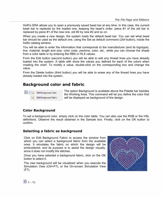
The File Page and Ribbons
HotFix ERA allows you to open a previously saved bead bar at any time. In this case, the currentbead bar is replaced by the loaded one, keeping the bead’s order: piece #1 of the old bar isreplaced by piece #1 of the new one, old #2 by new #2 and so on.
When you create a new design, the system loads the default bead bar. You can set what beadbar should be used as the default one, using the Set as default command (Def button), inside thehotfix catalog window.
You will be able to enter the information that corresponds to the manufacturer (and its logotype),line, material, length and size, color code, pantone, color, etc., while you can choose the shadefrom a color table or by entering the RBS or HLS values.
From the Edit button (second button) you will be able to edit any thread lines you have alreadyloaded into the system. A table with show the values you defined for each of the colors whencreating the chart. To modify a value, double-click on the corresponding box and change thevalue.
From the Delete button (third button) you will be able to erase any of the thread lines you havealready loaded into the system.
Background color and fabric
The option Background is available above the Palette bar besidesthe Working Area. This command will let you define the color thatwill be displayed as background of the design.
Color Background
To set a background color, simply click on the color table. You can also use the RGB or the HSLdefinitions. Observe the result obtained in the Sample box. Finally, click on the OK button toconfirm.
Selecting a fabric as background
Click on Edit Background Fabric to access the window fromwhich you can select a background fabric from the availableones. It simulates the fabric on which the design will beembroidered, and its purpose is to assist the design visually,since it does not modify the stitches.
Once you have selected a background fabric, click on the OKbutton to select it.
The new background will be visualized when you execute theSimulation View (Ctrl+F7), or the On-screen Simulation View(F7).
2 - 51

Hotfix Era – User's Manual
Page intentionally left blank
2 - 52

Chapter 3
Images and Vectors
Con ten t s :Working with Raster Images.............................................................................3
Supported image formats..................................................................3Open image........................................................................................4
Capture Image from Scanner................................................................5
Scale, rotate and move images manually............................................7Scale image & Shape...........................................................................8
Properties.....................................................................................10
Image Modes: Linked and Embedded................................................10Using Raster images as......................................................................11
Save................................................................................................12
Vectorize. Image to figure..................................................................12
Step 1 - Clean the image................................................................13
Step 2 - Vectorize..........................................................................15
Working with Vectors.....................................................................................17
Supported vector formats................................................................17Open a Vector File.............................................................................18
Get Vector from CorelDraw and Illustrator.........................................18
Paste Enhanced Metafile..................................................................18Create vector figures..........................................................................19
Shapes.........................................................................................19
Editor...........................................................................................19
Vectors based on TrueType texts......................................................20Editing Vector figures.........................................................................20
Vector Objects Selection ................................................................20
Scale and Rotate graphically............................................................22

Reshaping Vector Objects................................................................24Combining vectors (Shaping)..............................................................25
Group & Ungroup Vectors...................................................................26
Ungroup and Ungroup all.................................................................26
Alignment.....................................................................................28Vector Repetitions.............................................................................28
Export Vector Images.........................................................................30
Using Vector images as......................................................................31

Images and Vectors
Working with Raster ImagesWith Hotfix Era you can open a bitmap image of multiple formats and convert it into a hotfixdesign. With the image applied in the work area, you will be able to use it as reference guide andbuild up the necessary beads. In a quicker way you will be able to apply an automatictransformation from image to hotfix.
Note: You may insert an image before or after having started working on a design in Hot Fix Era this option will allow you to add new sections to designs that have already been started.
Supported image formats
The following formats are compatible with Hotfix Era
BMP – Windows Bitmap
JPG – JPEG Bitmaps
PCX - Paintbrush
TGA - Targa Bitmap
CLP - Clipboard Format
PNG – Portable Network Graphics
The working sequence with images is the following:
1) Acquire the image from the artwork by means of a scanner or use a graph created inany related application.
2) Scale the image to the final size.
3) Capture the design sections from the image outlines.
4) Save the design along with the reference image if necessary.
Below you will find details on each of these steps.
The Artwork ribbon contains all Hot Fix Era available commands to work with raster and vectorimages.
3 - 3
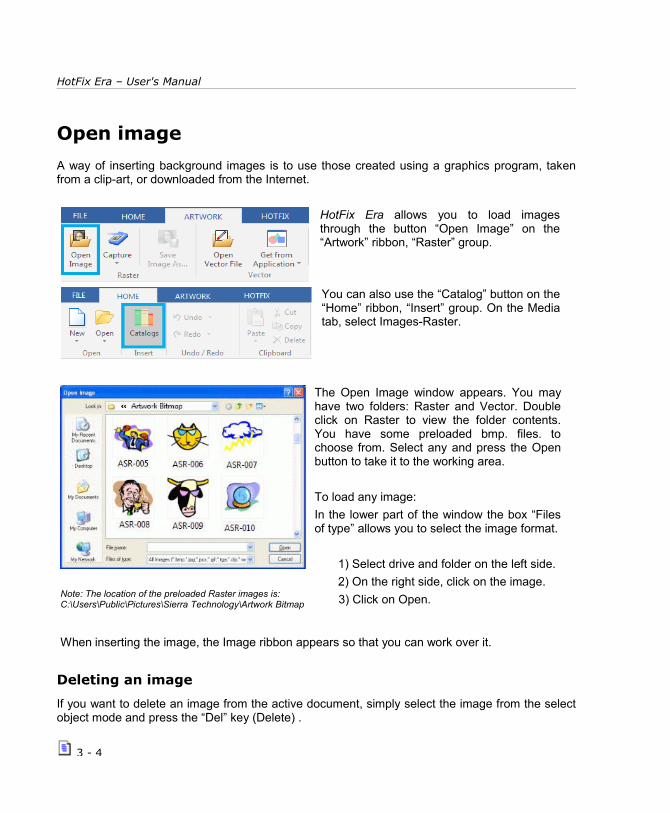
HotFix Era – User's Manual
Open image
A way of inserting background images is to use those created using a graphics program, takenfrom a clip-art, or downloaded from the Internet.
HotFix Era allows you to load imagesthrough the button “Open Image” on the“Artwork” ribbon, “Raster” group.
You can also use the “Catalog” button on the“Home” ribbon, “Insert” group. On the Mediatab, select Images-Raster.
Note: The location of the preloaded Raster images is: C:\Users\Public\Pictures\Sierra Technology\Artwork Bitmap
The Open Image window appears. You mayhave two folders: Raster and Vector. Doubleclick on Raster to view the folder contents.You have some preloaded bmp. files. tochoose from. Select any and press the Openbutton to take it to the working area.
To load any image:
In the lower part of the window the box “Filesof type” allows you to select the image format.
1) Select drive and folder on the left side.
2) On the right side, click on the image.
3) Click on Open.
When inserting the image, the Image ribbon appears so that you can work over it.
Deleting an image
If you want to delete an image from the active document, simply select the image from the selectobject mode and press the “Del” key (Delete) .
3 - 4

Images and Vectors
Capture Image from Scanner
From the Artwork ribbon click on the button“Capture” and then on “Scanner Capture” toopen the corresponding scanner dialog box.Complete the information required (mainlyresolution and color mode). Though the way ofworking depends of the scanner you haveinstalled, the normal process follows these steps:
1) Pre-scan to preview position and center image.
2) Select the area to be scanned.
3) Capture the selected area.
Once the scan is complete, the image will appear on the Hotfix Era's active document. Rememberthe following parameters; they are very important when obtaining an image from a scanner:
Resolution:
It is normally measured in dpi (dots per inch or points per inch) and it defines the brightness of thedigitized image. The higher the number, the neater the image, but it will also use more system’smemory. Except on 5x5 cm. or smaller images, a 300-dpi resolution is correct.
Color Mode:
You can capture an image in color or black and white. If you capture it in color, you must indicatethe number of colors to be used. On most cases, a 256-colors mode is enough; if you use morecolor, the resulting image will be better viewed but will take more memory. If you wish to capturethe image in black and white, you can use 256 shades of gray. Have the followingrecommendations in mind when scanning images:
Only scan the area of the image that you will work on. This will result in smaller, manageable images.
Use low resolution settings. On most cases, a 300-dpi resolution is enough. If youare going to work with the Photo type, the image used must have a high contrast level.
3 - 5

HotFix Era – User's Manual
Configuring the scanner
The scanner is a device that reads the images printed on paper orfabric. HotFix Era works directly with any Twain-compatible scanneralready installed on your Windows system.
Note: Most scanners come with Twain-interface software. Refer to your scanner manuals to obtain further information on the controllers and how to install them. Once a scanner has been configured, you will not need to repeat this process.
Since you may have more than one Twain device installed on your system (for example a scannerand a desktop digital camera), it will be necessary to indicate HotFix Era which device to use.Proceed as follows:
1) Click on Capture > Scanner Setup...
2) A Select Source dialog box opens, showing all the available Twain sources.
3) Click on the source that corresponds to the device to be used and press Select.
You may also insert a raster image using the Windowsclipboard. Using your favorite application, select the image andpress Ctrl+C.
This action copies the image to the Windows clipboard. Then,activate Embroidery Office and on the HOME ribbon,CLIPBOARD group, click on “Paste” and then on “PasteBitmap”.
The image will be inserted centered at the origin point (0,0).
Any time a raster image is selected, the Image ribbon is automatically displayed
3 - 6

Images and Vectors
Cropping Image
Click the button Crop Image and the cursor willchange, indicating that it is suitable for cutting.
Draw a rectangle over the area of the image that youwant to preserve and all the part inside the rectanglewill be preserved, the part in the outside will bedeleted.
Modifying Image Colors
Clicking on the button, opens a window, in which youcan quickly reduce the number of colors of theimage. The window is divided in two panes, oneshows the original and the other the results. It alsohas zoom tools and pan for your convenience. Whenyou are satisfied with the result press OK to take itback to the main working window.
Scale, rotate and move images manually
Click on Select Object (press F11) and click on the image you want toselect. The image will become surrounded by a box with highlighted corners and centers.
You can work with the corners and centers to expand, compress, move and rotate the image freely.
You can also use the commands to scale and align for a precise adjustment.
Note: Perform the necessary modifications on the image before starting to create the design. If you have already createdsections and you change the size, move or rotate the image, it will be difficult to modify the sections so as to adjust them tomodified reference image.
Click on the image and drag any of its corner nodes to adjust its size proportionally.
When dragging a determined corner node, the scaling will leave the opposite corner fixed in its position (right figure).
If you drag while pressing the Shift key, the scaling willbe performed keeping the center of the image in itsposition, while all the corners scale following themovement of the mouse.
3 - 7

HotFix Era – User's Manual
But, if you drag the pivot of any of the mid-sides, youcan change only one of the dimensions (horizontal orvertical depending on the dragged side), as shown inthe right figure. If you hold down the Shift key whiledragging, you will be able to move both vertical andhorizontal sides in a symmetric way.
Taking the mouse pointer next to the central zone, changes the cursors shape.
To rotate the image, while holding down the Ctrl key, click anddrag any corner node. Observe how the image border ismodified as well as the mouse pointer (right figure).
To finish this operation, simply release the mouse button.
Scale image & Shape
Once you have the image on the screen, whether it was in the disk orscanned, you can perform certain operations such as expand /compress, slant or rotate the image. Such modifications can be donemanually or controlled from the Image-Layout ribbon, changing thevalues of the boxes Size (Width, Height) and Position. If you want tomodify the size in the same proportion, you must activate the padlockicon as you can see on the example box of Size & Position.
Set Size (scale Tool)
This option allows you to precisely adjust the size ofa reference image, altering its original sizeaccording to the correct measure of the imagesegment. This allows you to work with an imagewith the same dimensions that the final designshould have.
3 - 8

Images and Vectors
The working method is the following:
1) Click on the Set Size icon. Click on any point of the image and drag it. HotFix Era will trace aline from the point to the mouse’s position.
2) Release the mouse buttons. The Image Scaling window displays the length of the traced lineand allows you to define the new value. Type in the corresponding size.
3) Clicking on OK, the image will be scaled so that the traced line has the indicated new size.
For example, if your design has to havea maximum height of 50 mm., afterinserting an image select the Measureand Scale tool, click on the upper part ofthe image (shown in figure as point 1),drag downwards up to the silhouette endand release the button in point 2, so thatthe Scale image box will open showingthe length between points 1 and 2, whileit allows you to indicate the newdimension that that distance has to have.
For this example, type 50 in the box placed at the right of the Height row, and press OK, all theimage is scaled so that the segment 1-2 measures 50 mm. You can also use the Width andHeight controls to give an exact size to the entire image.
Set Angle (Rotate Images)
Fixing the rotation angle is useful for some Works where you needprecision. Look at the next sample: We want the image to show thehand totally vertical and not as in the original image.
1) Click in Fix Angle and draw a line as indicated in the figure
2) Releasing the mouse button appears a dialog box to set thenew angle of the line drawn. Set the value “0”
3 - 9

HotFix Era – User's Manual
3) When pressing OK, the image will be rotated so that the linedrawn is horizontal, which means the hand is totally vertical.
Mirror/Rotate
The application gives you the possibility to rotate an image tospecific angles (90, 180 and 270 degrees) and to mirrorhorizontally and vertically in the working window.
Click on the button Mirror/Rotate to get the available options.
Properties
Saturation, Brightness and Contrast
This type of edition is the same as with anybasic image editor. Moving the slider of eachcontrol to modify the Artwork.
Transparency
From the box Properties you can modify thelevel of visualization of the image you have inthe working area. The lower the percentage oftransparency to dimmer the image will be. Atthe lowest value the image will dissappear.
Image Modes: Linked and Embedded
HotFix Era stores, inside the design file, information about the images you loaded, so they can bedisplayed the next time you open the design. By default, the images are “Linked”, that is, insteadof storing the image itself into the design, only the location within your disk is stored. This is goodto keep design files small but, if you move the design to another computer, the link fails. For those
3 - 10

Images and Vectors
cases, you may “Embed” the image, that is, instruct HotFix Era to store the image, not the link,inside the design file.
Linking Images
HotFix Era will save a link to the image, so the next time you open the design theimage will load with the same position, size and rotation angle. It is required thatthe image be kept on the disk with the same name and in the same folder whereit was when it was added to the design. This is the default behavior.
Embed an image
With the image selected, just click the button Embedded. HotFix Era will storethe image within the design file.
Images are automatically switched to embedded when you modify them, forexample when cropping or reduce its colors. This is also the default mode forimages pasted from clipboard.
Using Raster images as...
Reference images
Usually, images are loaded to be used as reference for design creation. Theywill become hidden when you activate the simulation window.
Open the Object Manager to see the Document Map, which consists ofseveral tabs. If a raster image is used as Reference, it should only appear inthe Auxiliary tab.
Screen Printing images
On some cases the image is part of the final design, for example asbackgroung of the embroidery. In this case, set the image as screenprinting,so it will be showed, along with your embroidery objects, in the simulationwindow.
Open the Object Manager to see the Document Map, which consists ofseveral tabs. If a raster image is used for Screen Printing, it should onlyappear in this tab.
All images no matter what kind they are will appear in the ALL tab.
3 - 11

HotFix Era – User's Manual
Save
If you are planning to work with an image taken from the scanner in severalsessions, you must save the image on your disk, so that it will be available the nexttime you open the design.
Save the file under EMF format, compatible with many programs that use vectorgraphics, DXF and PLT. Depending upon the format selected, the border and bodyor just the border will be saved.
To save an image:
1) Select the image.
2) Click on Save As, on the Artwork Image ribbon, Save group.
3) In the Save box, choose folder, name and format with which you want to savethe image and press Save.
It is recommended to use the default Image folder to save the images, even to save the newgraphic files that you copy or produce.
Vectorize. Image to figure
HotFix Era includes a complete vectorizer in order to transform a bitmap imageinserted in the working area in vector figures. Remember that you will be able toquickly create the sections of a design from each of these vector images.
To work on a bitmap image select it and activate the command Convert toVector, from the Image ribbon > Convert group.The Vectorizer box then appears. In it you will find a series of controls on theVectorizer ribbon, while the rest of the box will show a preview.
Observe at the top of the Previews there are three tabs, each of them allows you to visualize thethree stages by which a vectorized image should go through: the original figure, the clean figureand, finally, the vectorized result.
3 - 12

Images and Vectors
To make a zoom of the sample set outin the preview (in any of the tabs)using the command window availablein its lower left corner: you can make aspecific zoom, zoom in whole or pan.
Basically, you can follow two steps in order to vectorize the image. These are explained next:
Step 1 - Clean the image
This first stage implies reducing the complexity and noise of the graph, for the result to be asclean and clear as possible. Since HotFix Era vectorizes the image scanning its changes in tone,this first task is important in order to obtain good results. Have in mind that the cleaner and clearerthe image, HotFix Era will better interpret its shapes.
From the first sliding controls of the Vectorizer youcan optimize the image, trying to leave it as clean aspossible, clearly defining its shapes and borders andgetting out the colors mix that “dirty” the result,causing the so called impure images.
These controls are the following:
Reduction: Moving the slider to the right you reduce the number of colors in theimage, this is the first filter you should control, reducing the colors withoutdeforming the image.
Holes: This control eliminates the noise in the image, this noise is composed bysmall pixels dissociate color, called “holes”. As you move the slider towards theright, the application will eliminate the biggest holes.
3 - 13

HotFix Era – User's Manual
After configuring the controls,click on the Filter button for theapplication to show you the resultin the Clean tab of the Preview.
In the figure observe the Preview box after Filtering the image, see that the Cleaned tab is activated
According to the result obtained, modify the values of thecontrols previously mentioned, until the product look like whatyou expect. Do this as many times as necessary.
After cleaning the image and having obtained the convenientresult, use the two following controls. Their function isexplained below:
• Final Colors: From the colors view select those tones that are similar, and click on theCombine button for them to merge. It is convenient to reduce the number of colors of theimage when possible, in this way the application will be able to distinguish easily thechanges in tone, thus obtaining more precise vectorization. To select two or more colors,press Ctrl and click on the color to merge, then press the Combine button.
• Transparent Color: HotFix Era scans the image and captures the background color ofthe image so as not to include it in the vectorization since, when vectorizing thebackground color of the image it will form a figure that will “frame” the result. observe theimage on the right; it is a bitmap inserted as image in HotFix Era which background isgray.
Now, as an example, the following image will be vectorized changing its transparency color.
3 - 14

Images and Vectors
In the followingexamples, figure (a) isthe result of vectorizingthe image defining thegray color astransparent.
When converting intostitches, you will obtainthe result shown in (b).Note that the designdoes not reproduce thegray box that frames theoriginal representation.
On the other hand, figure(c) shows the result ofvectorizing the imageused as model specifyingthat the white colorshould be transparent. Inthis case, whenconverting all thevectorial figures institches sections, theresult will be the oneshown in (d).
Note: You should apply one or other method depending on the result you want to achieve.
Step 2 - Vectorize
Here you should transform the image (free from noise) in vector shapes.
Once you have created the vector-based figures, you will be able to work on them freely: you willbe able to scale them, modify their shape changing the nodes, change their color, etc. Thecreative possibilities, when the original bitmap image is vector-based, are many. It all depends onyour imagination.
For this to happen you must configure well theitems that define the characteristics of the createdvector (right figure). These are described below:
Max Error: This control defines the curvature degree that the trace will have. It increases orreduces the precision the vector curve will have regarding to the original bitmap.
3 - 15

HotFix Era – User's Manual
Sharpness: If you increase this value, the number of nodes that the created vector-based figurehas will decrease, thus obtaining a sharpened result.
These two controls define the curvature degree that the vector will have. High values of thesecontrols results in rounded outlines. If these items have small values, the trace of the vector-based figures will adjust to the outlines of the bitmap image.
Min. Area: It eliminates the small surfaces, according to the value specified in the sliding control.It is useful to exclude the smaller elements from the vectorization.
Observe the result that the chosen values will produce when vectorizing the bitmap image fromthe Vector tab in the Preview frame.
If you click on the OK button you will confirm the values entered to create the vector Figures.These will reproduce the shape presented in the Vector tab of the Preview.
Upon accepting, the vector figures will appear in the work area.
Finally, you must create sections as from these vector figures, choosing carefully the type and fillthey will have (See Chapter 4 Creating Hotfix Designs).
You must define the orientationof the direction lines, thelocation of the entry and exitpoints, the correct sequence ofsections, etc. according to thefigures that form the design.
3 - 16

Images and Vectors
Working with VectorsHotFix Era allows you to work with vector-based images; these are a new method to easilydigitize shapes of all types, also having the opportunity to combine two or more figures so as toobtain complex structures.
Once you obtain the desired figure, you will be able to convert it into a section (Auto-Digitizing)thus simplifying the creation process.
If these vector-based figures are not deleted before saving the document, they will be savedtogether with the design. This will be useful if you want to modify the created shapes in nexteditions.
Vector-based graph: Contrary to the bitmap graphs (or BMP) the vector-based figures arecreated as group of lines and not as individual points or pixels patterns.
Supported vector formats
The following formats are compatible with HotFix Era:
WMF - Windows MetaFiles
EMF - Enhanced MetaFiles
CDR – Corel Draw
CMX - Corel Presentation Exchange
AI - Adobe Ilustrator
Imaging - EO Imaging
DXF - Drawing Exchange Format
PLT - Vector Plotter Files
Note: To use the cdr and cmx formats you need Corel Draw ® installed in your system and the file opened in the application. To use the ai format Adobe Illustrator ® installed in your system and the file opened in the application.
All available methods to insert a vector artwork are available within the Artwork ribbon bar
3 - 17

HotFix Era – User's Manual
Open a Vector File
A way of inserting background vectors is to usethose created using a graphics program, takenfrom a clip-art, or downloaded from the Internet.Hotfix ERA allows you to load vectors from diskthrough the button Open Vector File on theArtwork ribbon > Vector group.
The Open window appears, showing the images available on disk in different formats. In the lowerpart of the window the box Files of type allows you to select the image format.
To load an image:
1) Select drive and folder on the left side.
2) On the right side, click on the image.
3) Click on Open
If you want to delete a vector from the active document, simply select the image from the select object mode and press the Delete key.
Get Vector from CorelDraw and Illustrator
HotFix Era is compatible with Corel Drawversions 10, 11, 12, X3, X4, X5, X6 and X7 andIllustrator if these applications are installed inyour computer.
In this way you will be able to insert any vector-based figure made in Corel Draw or Illustrator butnot bitmaps imported to Corel/Illustrator or word art.
Once working with HotFix Era you will be able to edit the figures in the same way that you workwith the vector-based created within the application.
Note: For the correct performance of these utilities, it is necessary for Corel Draw or Illustrator to be fully installed.
Paste Enhanced MetafileCertain image creation applications allow you to copy an image file typeyou are working on (Windows Metafile, EMF, etc.), to the Clipboard. Thisis recommended for certain sketches with a high level of elements, orwhen it is necessary to obtain more precision (better level of detail). Youmay then paste it in Hotfix ERA using these commands.
3 - 18

Images and Vectors
Create vector figures
With HotFix Era you can create vectorial figures in differentways: from the Artwork ribbon > Shapes group.
The geometric figures available to insert are organized inShapes, Editor and Text figures. You can also create vectorfigures manually with bezier curves or freehand.
Bézier: This tool is based on the sketch possibilities that allow Bezier curves.
FreeHand: To trace freely open figures, drawing directly in the working area.
Shapes
To insert any of the figures, choose the tool from the Artwork ribbon >Shapes group. Form the list that appears, you have Basic and AdvancedShapes; Extended Shapes; Puzzle1 and Puzzle2. Click on the desiredone. Then, press the left mouse button on a point of the working areaand drag without releasing it, while doing this the shape of a figure willbe progressively formed. To produce perfect squares (if working withrectangles) or perfect circles (if working with ellipses), keep the Ctrl keydepressed while dragging the mouse.
Once the outline has the size and shape you need, release the mousebutton. Immediately after creating the figure, it will become editable foryou to adjust its size and shape.
EditorHot Fix allows you to create vector figuresusing a very easy interface.
Select the type of vector you want tocreate: Polygon, Star, Lines or Spiral;adjust some Parameters;
Select if you want the outline or a solidfigure, and their corresponding color.
Press OK to create the figure.
3 - 19

HotFix Era – User's Manual
Vectors based on TrueType texts
Pressing this button opens a dialog box that allows you totype text or lines of text, including selecting the font and size,alignment and presentation.
To create multi-line texts, once you have inserted the first text, press CTRL + Enter to begin a new line, and type the second text.
Once you have finished inserting the text, press the green check, to take it to the working window.
Any time a vector is selected, HotFix Era shows the Vector ribbon with all the tools to work withthem.
Editing Vector figures
Vector Objects Selection
All vector figures inserted in Embroidery Office are editable, such transformations are done usingthem together or modifying nodes individually.
To select any object located in the main work area press this button, click on the object you want.Immediately see a box on it that lets you manually resize, while the ribbon changes to provide thenecessary tools needed to edit the object.
3 - 20

Images and Vectors
Click on the Select Object button to display the selectionoptions:
Select by rectangle
From left to right: Select the objects that are fully included in the boxFrom left to right: Select the objects "crossed" by the rectangle.
Select by outline
Draw an outline "node to node" around the figure you want to select. When you finish surroundthe object, press ENTER or mouse middle button and the object will be selected. This mode ofselection is really useful when you have overlapping figures.
Select all objects
Select all objects (vectors, images, embroidery and / or stone that are in the work area.
Invert actual selection
Change the selection excluding selected items and selected those that were previously outsidethe selection.
Selecting two or more figures
To select several figures close between each other you can click on the working area and, withoutreleasing the mouse button, move until the dotted box embosses the figures you want to work on(next page figures).
You can also select more than one figure by pressing the Ctrl key and clicking on the elements you are going to work on.
Instead, if you press the Shift key at the time of clicking two figures, you will select all thoseobjects that are between both figures in the corresponding sequence.
3 - 21

HotFix Era – User's Manual
Scale and Rotate graphically
In certain figures (for example the triangle) themodification points appear active (left image).These allow you to change the original shape.
The vector-based figures (either created fromHotFix Era or imported from differentapplications) are liable to transform, modify theircurves, merge and convert to hot fix sections.
You can expand, compress, rotate and moveimages manually, in the same way you can do itwith any other image (right figure).
Press the Ctrl key to rotate the figure or modify its rotation pivot.
Press the Shift key to modify the size of the figure fixing its center.
If necessary, before you continue working with the figure, adjust its aspect and location, since bydragging the corners you can proportionally modify the height and width at the same time, whileby dragging the pivots you expand or compress the figure in one direction (either the height or thewidth).
To move the figure to another location of the working area, simply place the mouse pointer to thecenter of the figure and when this pointer changes its shape (cross with four arrows), click anddrag towards the desired position.
To perform modifications in more than one figure at the same time, simply select the figures thatwill be involved in the modification and perform all actions on all of them at the same time.
These figures are placed following the order in which they were created, reason why some will beon top of others.
3 - 22

Images and Vectors
Edit Nodes
The vector-based figures are made of nodes, that behave similarly tothose that make the embroidery sections. For more information about theoperation with nodes see chapter “Manual Basic Digitizing”.
Once the vector-based figure has been created you can modify the nodesthat give shape to it as well as the layout of each node’s handles.
To do so, click on the Select Object tool, and then on the desiredfigure. From the context menu, click on “Convert to Curves”, to see itsnodes.
Now that the figure has been converted into curves you will be ableto alter its geometry, modifying the location of its nodes and thelayout of its handles.
You can also eliminate nodes, create new ones, etc. Operate on thenodes in a similar way to that used when you work on the nodes ofan embroidery section. These options are available from the contextmenu.
Vector Color and Format
This box allows to modify the border and fill color of thevector-based figure selected, modify the border width oradd/remove it.
You can choose a vector only with fill, only with border orboth. In the left picture both are selected.
This option is useful for those cases where you must work on several overlapped figures.
On the right figure please note that the color of each figure has been modified, improvingconsiderably the visualization of the elements.
3 - 23

HotFix Era – User's Manual
Setting colors from the color palette
The color bar or color palette may be used to set or change the border and fill color of vectorobjects. With a vector object selected, clicking any color within the palette will fill that object withthe pointed color. Right clicking on the color, sets the border color for that object.
The first element in the color palette is a special item. It represents the “No color”entry and may be used to remove the border and fill color of vector objects.
Clicking the no color item eliminates the vector fill color
Clicking the no color item with the right mouse button, eliminates the vector border
Managing Color PalettesEdit this Palette: Allows you to access a dialog boxwith options to select and edit a color palette.
Load, Save and Delete a color palette: Get a dialogbox that lets you work with color palettes.
Set this Palette as Default: Each time you open adocument vector, this color palette appears.
Reshaping Vector Objects
Vector Split
This tool allows you to split a vectorobject using an arbitrary line (defined bya sequence of nodes).
Once the splitting line is defined, pressthe Enter key, to execute the operation.
This tool is also available from the context menu.
Remove Holes
Automatically deletes all theholes of the selected vectorobject.
3 - 24

Images and Vectors
Combining vectors (Shaping)
Using the Shaping tools it is possible to create shapes resulting fromthe intersection of two vector-based figures. Have in mind that if youhave full command of this technique you will be able to sketchcomplex shapes with little effort.
In this way, the combination of several shapes creates one onlyfigure (in most cases), or performs modifications in the geometry ofboth figures. You can combine the different types of figures availablein the application so as to create new shapes easily. The procedureto combine figures is the following:
To give an example we will apply each of the described combinations to the figures presented inthe below figures, so you can observe the different results obtained.
Addition Substraction Intersection
Exclusion Trim Simplify
This tool is available from the Artwork – Vector – Layout ribbon > Combine group > CombineVectors or from the context menu. It is very useful whenever you have to work on vector-basedimages, since some shapes are made up by several figures, and many of them can beoverlapped.
In the three figures next see how the vector-based drawing is formed, pay attention to the numberof overlapping zones it has.
3 - 25

HotFix Era – User's Manual
In figure (a) appreciate how you view the image in EO Design’s Graphic View, see that it looks like one only element at first sight.
Nevertheless, in figure (b) you can see the outlines of each of the figures that form the sketch. You can see that it is composed by several overlapping elements, one on top of the other.
In figure (c) each of the overlapping zones were painted in gray. Note that there are darker areas, since several figures overlap there.
Group & Ungroup Vectors
It is possible to group two or more vector-based figures to be considered aunit. In this way, it will be possible to move them, apply the sametransformations in shape and other changes to all the figures in the group atthe same time.
It is also possible to merge other groups already created, thus creating nestedgroups.
To create a group select the figures to activate the Group command from the Artwork – Vector –Layout ribbon > Grouping group or from the context menu (Group Objects > Vectors group).
Ungroup and Ungroup all
To ungroup the figures that form a group, select the group and then choose theoption Ungroup. If you have created nested groups (groups made by othergroups), the Ungroup command explodes just one level, while the Ungroup Allexplodes all the groups and returns the original objects completely ungrouped.
This option is very important whenever you insert wmf or emf images, since it is made up by aseries of grouped vector-based images.In order to edit any of these figures, you must first apply this function.
3 - 26

Images and Vectors
Two grouping levels Ungroup Ungroup All
Vector Order
In the edition of vector-based figures, you will be able to modifythe layout of the vector-based shapes from Ribbon Vector >Grouping > Order or from the context menu options.
The options are:
Front: It sends the selected element to the front, before the rest of the objects, placing it in the forefront.
Back: It places the selected object behind the rest of the objects.
Move Forward: The figure selected moves one level forward.
Move Backward: The figure selected moves one level backwards.
Accurate Size & position control
Once you have the image on the screen, whether it was in the disk orscanned, you can perform certain operations such as expand /compress, slant or rotate the image. To access these tools, select avector and press the Block Layout tab, Position and Size group.
Position: This button commands the movement on the vertical axis and the horizontal axis of thefigure. Take the center line marking the upper box surrounds the figure.
Size: This group lets you precisely control the size of the object. The padlock icon sets theproportional mode: when pressed, changing one of the object's dimensions (width or height) willautomatically adjust the other in order to keep the object aspect ratio. When unchecked, you cancontrol both, width and height independently.
3 - 27

HotFix Era – User's Manual
Clicking on the small icon at lower-right corner will open abox from where you may set the dimensions as a value orpercentage.
The options to rotate a vector by setting the rotation angle, works the same way as for bitmapimages.
Alignment
These functions allow you to place the vector figure on the left, right, top,bottom or center, in both directions or in either of the two.
To access these tools, select a vector and press the Block Layout tab,Align group.
You will also be able to access the tools from the vector´s context menu.
To Object: This tools aligns the objects inside the block to left, right, top and bottom, using asreference the leftmost, rightmost, upper and lower object of the block. You can also align theobjects center horizontally, vertically or both.
To Design: Contains tools for align the hole block with respect to the design, that is, with respectto all other objects not included in the block.
Center at origin: Moves the center of the block to the system origin point (0,0)
Vector Repetitions
The following functions allow you to repeat one or more times the selectedfigure/s. You can access these commands from Artwork - Vector - Layout >Create Objects group or from the context menu options.
Duplicate
This command performs a copy and paste of the selected vector/s in only one step. Italways works on the active document. Pressing the button more times makes anothercopy of the selected vector/s you copied the first time.
3 - 28

Images and Vectors
Matrix Repetitions
Use this function to duplicate the vector/s a certain number of times; the copies of thevector/s will appear adjusted to a mold in the shape of cells.
Define the number of rows, columns and the horizontal and vertical distance from the matrix cells.To work with this tool, follow the procedure below:
1)Select a group of vectors (paw) and from the Layout tab clickon Matrix Repetitions.
2) In the Matrix box set the number of rows and columns, andthe distance between them, horizontally and vertically.
Click on OK to see the result in the work area, the vector/swill repeat a number of times depending on the valuesentered.
In the example shown in the left figure we chose a numberof 2 rows and 4 columns to repeat the paw vector.
Contour with Offset
Use this function to create one or more vector lines, outside or inside the original vector'sshape outline (contour) separated a defined distance one from the other.
After selecting Contour with Offset, the “Create contour” window will open. You have severalpredefined contour options to choose from:
Outer Contour, that makes the newvector/s towards the outside of the originalvector;
Inner Contour, that makes the newvector/s towards the insides of the originalvector;
Custom, lets you define whether you wantto make an inner or outer contour; theorder in which the vectors will be made; thenumber, separation and color of the newlines.
Last Used shows the most frequent ones.
Favorites shows all the ones which you have marked as favorites in Outer or Inner Contours. Tocopy a predefined contour to the favorite tab, just go to the Outer or Inner Contour tabs, click onthe desired one and press the yellow star found on the same tab.
Also on the Inner and Outer Contour windows, you have an Edit button on the right that let´s yousee and modify the selected contour.
3 - 29
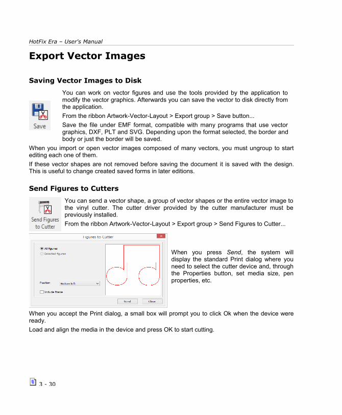
HotFix Era – User's Manual
Export Vector Images
Saving Vector Images to Disk
You can work on vector figures and use the tools provided by the application tomodify the vector graphics. Afterwards you can save the vector to disk directly fromthe application.
From the ribbon Artwork-Vector-Layout > Export group > Save button...
Save the file under EMF format, compatible with many programs that use vectorgraphics, DXF, PLT and SVG. Depending upon the format selected, the border andbody or just the border will be saved.
When you import or open vector images composed of many vectors, you must ungroup to startediting each one of them.
If these vector shapes are not removed before saving the document it is saved with the design.This is useful to change created saved forms in later editions.
Send Figures to Cutters
You can send a vector shape, a group of vector shapes or the entire vector image tothe vinyl cutter. The cutter driver provided by the cutter manufacturer must bepreviously installed.
From the ribbon Artwork-Vector-Layout > Export group > Send Figures to Cutter...
When you press Send, the system willdisplay the standard Print dialog where youneed to select the cutter device and, throughthe Properties button, set media size, penproperties, etc.
When you accept the Print dialog, a small box will prompt you to click Ok when the device wereready.
Load and align the media in the device and press OK to start cutting.
3 - 30

Images and Vectors
Using Vector images as...
Auxiliary images
They are loaded just to be used as reference for design creation.
When you enable the Simulation View, the Auxiliary images will becomehidden. To view the auxiliary images again, just disable the simulation view.
Open the Object Manager to see the Document Map, which consists ofseveral tabs. If a vector image is only used as reference, it should onlyappear in this tab.
Cutter images
These figures are the ones that will be sent to the cutter device.
When you enable the Simulation View, the Cutter figures will be visible onthe workspace.
You can turn an auxiliary image to a cutter one, just by selecting the auxiliaryimage and clicking on the Cutter button. The converted image will no longerappear in the Auxiliary tab, but will be now shown in the Cutter tab.
Screen Printing images
You may load an image that is part of the final design, for example as backgroung of the embroidery. When you set an image as screenprinting, it will be showed, along with your embroidery objects, in the simulation window.
When you enable the Simulation View, the Screen Printing figures will bevisible on the workspace.
You can turn an auxiliary or cutter image, to a Screen Printing one just byselecting the desired image and clicking on the Screen Printing button. Theconverted image will no longer appear in the original tab, but will be nowshown in the Screen Printing tab.
All images no matter what kind they are will appear in the ALL tab.
3 - 31

HotFix Era – User's Manual
Page Left blank
3 - 32

Chapter 4
Creating Hotfix Designs
Con ten t s :HotFix ERA Objects.....................................................................................................................3
About Nodes.......................................................................................3
Paths.................................................................................................5
Areas................................................................................................6Areas with Hotfix Uniform Fill.............................................................7Areas with Hotfix Inner Ring Fill.........................................................8Areas with Hotfix Flexible Fill...........................................................10Areas with Hotfix Flat Fill.................................................................11Areas with Hotfix Grading Fill...........................................................12Areas with Hotfix Textures...............................................................14Areas with Hotfix Spectacular Fill......................................................17Areas with Hotfix Outer Ring Fill.......................................................19Ray Hotfix Column.........................................................................22Path and Areas with Hotfix Assorted Fill.............................................24
Manual Hotfix....................................................................................25
Hotfix Texts......................................................................................25Creating Hotfix objects..............................................................................................................25
Manual Digitizing...........................................................................26Assisted Digitizing: Autotrace...........................................................26Automatic Digitizing: Auto Complete.................................................28Digitizing using Geometric Shapes....................................................28
Editing Hotfix objects...............................................................................................................29
Object Selection tools.........................................................................29
Hotfix piece edition tool......................................................................30
Working with Hotfix Objects Blocks......................................................31
Repetitions.......................................................................................33
Effects on Hot fix objects....................................................................33Move Random................................................................................34Color Random................................................................................34

Color Blending...............................................................................35Grayscale Photo Stone....................................................................35Color Photo Stone..........................................................................37Whirl............................................................................................38Sphere.........................................................................................39Grid Transformation........................................................................39
Object Manager and Object Inspector...................................................................................40Object Manager.............................................................................40Object Inspector............................................................................41
Sorting pieces.........................................................................................................................41Cleaning overlapped pieces...................................................................................................42Importing YNG files................................................................................................................43Importing PLT files..................................................................................................................45Importing DST files.................................................................................................................46

Creating Hotfix Designs
HotFix ERA ObjectsThe software offers many types of hotfix objects which can be used to create hotfix designs.Those tools have been grouped in: Single HotFix and Assorted HotFix according to the number ofhotfix types present on the main fill. In addition, you may also create text with HotFix and placeindividual HotFix manually. Some objects are lines (paths) and other objects are areas (regions),on for both Single HotFix and Assorted HotFix groups.
Note: The number of available HotFix object types and fill styles depend on the purchasedproduct. Some of these features may be optional for standard products.
Choosing what object type is better, depends on the design feature you are working on: openshapes should be digitized with paths, closed filled shapes with areas, etc.Every object type has specific features, properties, and a specific tool to create it.
The creation tools can be enabled through different ways:
(1) From the HotFix Tab, on theInsert HotFix Objects group, select the required object type and choose the fill style.
(2) From the Create Sections button, select the required object type and choose the fill style.
(3) Press the “Smart Design” button to access the Smart Design tool, and select the appropriate creation tool and fillstyle.
About Nodes
The following paragraphs introduce the HotFix ERA objects, their elements, fill modes, andproperties. The object's boundary (what we call the object's “main reference”) are built by insertinga sequence of points called “nodes”. Nodes are more than simple points; they have someproperties that let you control how the system connects them: with a straight line, with a smoothcurve or with a sharp curve.
At the moment of manual tracing you can specify two working modes: Arc Nodesor Bezier Nodes. According to which one you choose, the nodes will behavedifferently.
Though working with Circular Arcs, will be easier for you to capture geometric shapes, it generallyrequires the insertion of more nodes. On the other side, working mode with Bezier curves
4 - 3

HotFix ERA – User's Manual
requires a better skill when capturing shapes, but allows you to reduce the number of nodes thatform the geometry of a section. This mode is recommended for those users who normally designwith vector-based applications that use this type of curves (for example, CorelDraw®).
The default working curve type is Bezier but you can modify it to Circle Arcs from the Home ribbon> System group > System Settings --> Application > Create & Edit > General > Curves type item.
Once a creation tool is activated, the ribbon changes to display the properties and controls thatapply to that specific object.
All creation ribbons contain two groups; one, the Digitizing Methods from where youcan define whether to work with Bezier or Circle Arcs;
and the other called Digitizing Objects from where you can control node’s properties.
There are two basic node types:Straight Type:
Represented by square nodes. Connects nodes with a straight line.
Curve Type:
Represented by circular nodes.
Connects nodes with a curved line.
There is an extra property for both node types, although its effect is more visible for curve nodes:
Normal Type:
Curvature of the segments onboth sides of the node is thesame. Displayed in white color.
Corner Type:
Curvature of the segments on bothsides of the node may be different,letting you get a sharp point in theshape. Displayed in cyan color.
Note: If you switch a straight node between Normal and Corner you will not see any difference in the shape (just the node color will change). However, it may have impact on the beads placement because the system will always try to place a bead at the corner nodes.
Curve nodes have also a special control that lets you define the curvature of the segments at bothsides of them. These controls, called “handles”, are small segments with a dot at the end that youcan move (by dragging them with the mouse) to establish how the curved segments behave at thenode.
The picture at the left shows the samecurved node with three differentpositions of the handles. Handles maybe moved near or far from the node toget a sharper or smoother curve andmay be rotated around the node tochange concavity.
There is a property for normal curve nodes that adds some extra control for the handles:
4 - 4

Creating Hotfix Designs
Symmetric: Force that both handles are the same size, making the curvature of thesegments at both sides of the node, equal. When you move one of the handles, theopposite ones is automatically moved at the same distance with respect to the node.
Uniform: Both handles may be set at different distances with respect to the node,although they are forced to remain aligned.
When the curve node is marked as acorner, its handles may be set atdifferent distances from the node andmay have different directions.
The picture shows the same corner curvenode with different positions of itshandles. Note that handles may be setat any distance from the node and theyare not aligned.
PathsPaths are linear objects, with beads arranged along them. They are simply defined bya sequence of nodes. They may be open or closed, may have smooth or sharp curvedsegments (controlled by the properties of its nodes) and also may intersectthemselves.
One basic fill mode is available for this type of object: beads are arranged along the path, trying tokeep the same distance between them. The properties to control this placement (the fill modeproperties in HotFix ERA terminology) are:
Beads Spacing: Controls the space between beads. A distance of 0 (zero)means that beads are “touching” its neighbors.Fitting mode: This property controls how beads are spread along thepath. Four options are available (from left to right):Path: This is the default and more common option. Beads are uniformlyplaced along the path, but considering:
Always a bead is placed in the position of the first and last node andalways a bed is placed at the nodes where direction of the segmentschanges abruptly.
References: The system places beads at the position of nodes only. Thevalue entered for Distance value is ignored.
Path + References: The system places beads at the position of the nodesand fits additional ones between them using the configured Distance value.
Paths + Corners: Similar to the Path option, but with an extra rule: Alwaysa bead is placed at the corner nodes.
4 - 5

HotFix ERA – User's Manual
Angle mode: Non round beads may be oriented, that is, place rotated(with respect to its center) at different angles. Orientation may be fixed (allbeads at the same angle) or may be variable, considering the pathdirection. This property has three options that let you control beadsorientation (from left to right):Perpendicular: Beads are oriented following a variable directionperpendicular to the path.
Tangent: Beads are oriented considering a direction tangent to the path.
Fixed: This is the default option. All beads are placed at a the fixed angleindicated in Angle Value.
Angle value: Available only for Angle Mode = Fixed, indicates the angleused to rotate the beads. The default value is 0 (zero). Angle is measuredwith respect to the document horizontal axis.
Bead Type: This control lets you select the bead you will use for theobject. Clicking on it unfolds the current bead palettes that allows you toselect any of the pieces contained on it.
Note: The distance between beads is not exactly preserved all the time. To fit beads properly, the system smoothly adapts thedistance using the entered value as a mean value.
AreasThe term Area refers to an object defined by a closed boundary. Normally, beads are placed in theinner region of the area and, optionally, also along its boundary. HotFix ERA defines someadditional elements for the area objects:
Holes: Are regions inside the main reference, where no beads are placed. Once the mainreference was created, select Hole from the Element group at the ribbon, to add a hole tothe area object. Holes are closed shapes, so, if you created an open shape, the system willclose it automatically.
Direction lines: Are special geometric references, used in some fill modes, to guide thebeads placement. Directions are open shapes, build with straight and/or curve nodes in aprocess very similar to the Path object creation. To add a direction you just need to click theDirection button located at the Element group in the ribbon bar.
Area objects support a combination of fill modes, one for the inner region and one for theborderline. Borderlines are simply processed as closed paths. For the inner region, there are fourfill modes available: Uniform Fill; Inner Ring Fill; Flexible Fill and Flat Fill. The basic differencebetween them is the style in which the beads are arranged, producing different visual effects.
4 - 6
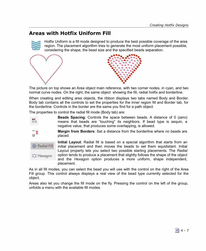
Creating Hotfix Designs
Areas with Hotfix Uniform Fill
Hotfix Uniform is a fill mode designed to produce the best possible coverage of the arearegion. The placement algorithm tries to generate the most uniform placement possible,considering the shape, the bead size and the specified beads separation.
The picture on top shows an Area object main reference, with two corner nodes, in cyan, and twonormal curve nodes. On the right, the same object showing the fill, radial hotfix and borderline.
When creating and editing area objects, the ribbon displays two tabs named Body and Border.Body tab contains all the controls to set the properties for the inner region fill and Border tab, forthe borderline. Controls in the border are the same you find for a path object.
The properties to control the radial fill mode (Body tab) are:Beads Spacing: Controls the space between beads. A distance of 0 (zero)means that beads are “touching” its neighbors. If bead type is sequin, anegative value, that produces some overlapping, is allowed.
Margin from Borders: Set a distance from the borderline where no beads areplaced.
Initial Layout: Radial fill is based on a special algorithm that starts from aninitial placement and then moves the beads to set them equidistant. InitialLayout property lets you select two possible starting placements. The Radialoption tends to produce a placement that slightly follows the shape of the objectand the Hexagon option produces a more uniform, shape independent,placement.
As in all fill modes, you can select the bead you will use with the control on the right of the AreaFill group. This control always displays a real view of the bead type currently selected for theobject.
Areas also let you change the fill mode on the fly. Pressing the control on the left of the group,unfolds a menu with the available fill modes.
4 - 7

HotFix ERA – User's Manual
Areas also let you change the fill mode on the fly.
Pressing the control on the left of the group, unfolds a menu with theavailable fill modes.
The number of modes depend on the system level you acquire.
Areas with Hotfix Inner Ring Fill
In this fill mode, the system calculates a group of interior rings and places the beadsalong them. The special feature of the Variable Distance fill mode, is that you can controlthe separation between the rings, in a one by one basis, allowing beads density gradientsthat produce interesting effects.
Ring fill mode is better suited for large area objects with small beads. This combination allowsthat several rings may be fitted inside the shape so the distance variation effect may becomeevident.The properties to control the Variable Distance fill mode (Body tab) are:
Beads Spacing: Controls the space between beads along all of the rings. A distance of0 (zero) means that beads are “touching” its neighbors. If bead type is sequin, anegative value, that produces some overlapping, is allowed.
Margin from Borders: Set a distance from the borderline where no beads are placed.
Pattern: This button displays the Rings Pattern dialog box. This tool lets you use any ofthe Radial Patterns included; or to edit them to create a new one.
4 - 8

Creating Hotfix Designs
The Rings Pattern box shows someRadial Pattern samples you can use.Click on the All option, select one andpress OK.
You can also edit any of them, changetheir configuration and use it right away. Itwill appear under the Custom option.
To access any Ring Pattern quicker, addit to the Favorites tab, first select one ofthe available ones, and afterwardsclicking on the yellow star. It will appearon your Favorites tab.
Choose any pattern, for example the one named RI11-001, press the Edit button to see thenumber of rings the pattern has, and a preview pane on the right.
The Rings control is set to 1 and the list contains just one row. You may define as many rings asyou want, however:
• If the number of defined rings andtheir separations produce a patternthat is not enough large to completelyfill the object, the system will repeatthe pattern starting with ring 1.
• If the number of defined rings andtheir separations produce a patternthat does not fit inside the object,some rings will be ignored. In thiscase, the system shows a warningmessage and the ignored rings will bemarked with * in the list.
The Rings Pattern settings in the picture above was used to fill the star design shown in theprevious page. Seven rings were defined. The separation between them was increased fromring to ring to produce the vanishing effect.
The red line in the Preview panel indicates the object boundary. The black background regionrepresents the object interior.
Observe that the last ring falls outside the black region, meaning that it will not fit and will be ignored. For this reason the warning message appears at the bottom and the ring 7 is marked with *. If you scale the object, maybe the object that does not fit in, will fit.
4 - 9

HotFix ERA – User's Manual
Angle mode: Non round beads may be oriented, that is, place rotated(with respect to its center) at different angles. Orientation may be fixed (allbeads at the same angle) or may be variable, considering the pathdirection.
This property has three options that let you control beads orientation(from left to right):
Perpendicular: Beads are oriented following a variable directionperpendicular to the path.
Tangent: Beads are oriented considering a direction tangent to the path.
Fixed: This is the default option. All beads are placed at a the fixed angleindicated in Angle Value.
Angle value: Indicates the angle used to rotate the beads. The defaultvalue is 0 (zero).
Areas with Hotfix Flexible Fill
Flexible Hotfix is a powerful fill mode that allows you to create a beads placement thatis guided by an almost arbitrary direction line.
This fill mode requires that a new element to be defined, the direction line. It’s a simple,open line, built from a sequence of nodes (straight and curves).
Basically, the placement is generated using a set of imaginary lines(with the same shape than the direction line).
Beads are then placed along these line in a row by row basis.
So, this fill mode includes properties not only to control beads spacingalong the “imaginary” rows but rows spacing as well.
Once you complete the input of the main reference, from the Elements group in the HotFix Area Body ribbon, click on the Direction icon. Then just start creating a line thatcrosses the main reference, like in the picture above right. Press Enter to confirm.
4 - 10

Creating Hotfix Designs
Direction line is not mandatory; you may enter it or not. In the last case, the system uses aninternal and invisible, horizontal straight line. The Body tab of Flexible fill shows the followingproperties:
Beads Spacing: Controls the space between beads along a row. A distance of 0 (zero)means that beads are “touching” its neighbors. If bead type is sequin, a negative value,that produces some overlapping, is allowed.
Rows spacing: Controls the spacing between rows.
Margin from Borders: Set a distance from the borderline where no beads are placed.
You can select the bead you will use with the control on the right of the Area Fill group. Thiscontrol always displays a real view of the bead type currently selected for the object.
These Area types also let you change the fill mode on the fly. Pressing the control on the left ofthe Area Fill group, unfolds a menu with the available fill modes.
Areas with Hotfix Flat Fill
Hotfix Flat fill mode produces a regular, column by row based, beads placement. Bettersuited for large or very geometric shapes, it does not require additional geometricreferences and allows you to control column and row spacing, beads angle, etc.
Properties available in the Body tab for this fill mode are:
Columns spacing: controls horizontal beads separation.
Rows spacing: controls vertical beads separation.
Beads Offset: Sets an initial displacement for placement of beads in even rows. Grid fillmode produces regular, vertically and horizontally aligned placement., but sometimes,shapes require a bit irregular placement. Offset helps this avoiding the vertical alignment.The value is a percentage. Best effect is obtained with 50% offset.
Beads angle: Set the rotation (around its center) angle of the beads. Useful for nonround pieces.
4 - 11

HotFix ERA – User's Manual
Border mode: Instructs the system how to place beads at the object boundaries. Insideoption (upper left), forces to remove the beads that are not completely inside the objectboundaries. Outside option (lower left) allows beads that are placed crossing the objectboundaries.
Placement Tolerance: Usually, if columns and rows spacing values are consideredstrictly, some beads do not fit and should not be placed. However, sometimes theplacement would look better if some pieces in that situation were allowed. Tolerancecontrols how strictly the system behaves in these “limit” situations. A value of 0% (zero)means no tolerance at all, and larger values relaxes the placement rule allowing some“limit” pieces to be included.
Areas with Hotfix Grading FillOPTIONALFEATURE
Grading fill mode produces a bead placement where the spacing varies gradually alonga specified direction allowing the creation of interesting volumetric effects.
Basically, you define a “variation line” and indicate an initial and final spacing values.
By default, the system places the variation line starting at the center of the area object andending near the area edge; initial spacing is set by default to a value lower (more denseplacement) than the final spacing, but you may change it according to your needs.
You need to access the context menu and select Customize Hotfix Area to display the variationline. You may drag the line ends (square and triangle marks) to modify the line size and position.
An additional rectangular mark (called average spacing cursor) defines the position where thebeads spacing will be set to the average value between the initial and final ones. You may dragthe cursor (always on the line) to any position.Once the line is defined, it rules the beadsspacing and the system will place the beads with spacing values that will vary gradually frominitial to final values.
Properties available in the Body tab for this fill mode are:
Initial Spacing: controls beads spacing at the starting point (square mark)
4 - 12

Creating Hotfix Designs
Final Spacing: controls beads spacing at the ending point (triangle mark)
Half Grading Point: Defines a point where spacing is the average value betweenInitial and Final values. Position of this point is represented as a value in the range0.1 to 0.9, where 0.1 is located near Initial point and 0.9 is located near Final point
Grading Variation Mode: This control defines how spacing variation isaccomplished. Radial mode (lower left) produces variation following concentriccircles around the Initial point, while Linear mode (lower right) produces variationfollowing an imaginary line perpendicular to the direction line.
Areas with Hotfix Textures
Textures are predefined bead's arrangements that can be used to fill area objects. Youmay imagine the textures as a large pre-built design where your area objects behaveslike a clipping boundary.
You may select what region of the texture is clipped by your area and even scale the texture so asit better fits your needs. The idea behind textures is to allow you to create artistic and geometriccomplex and time consuming bead placements, in a very short time and with just some few clicks.
The basic steps to use textures are:
1- Within the Hotfix ribbon, select Area with Assorted Hotfix Fill and then Area with Texture Fill.The system displays the Hotfix Area Body ribbon, with the Default texture selected.
2- Create the area object as usual. Consider that texture fill is intended for medium to large sizeareas. You may not appreciate the texture pattern if you use very small areas. As a guideline,avoid objects smaller than 50 x 50 mm.
3- Once the area contour is completed, the system will show a sketched view of the texture,drawn using a contrast color. In this state, you may move the texture regarding your areaboundaries by simply dragging with the mouse; also, if you drag while holding the Shift key, youmay scale the texture pattern. If you hold the Ctrl key and drag you may rotate the texture.
Textures are designed using a predefined bead type and spacing. However, you may changethem using the ribbon controls during creation or later, during edition. Again, consider that using
4 - 13
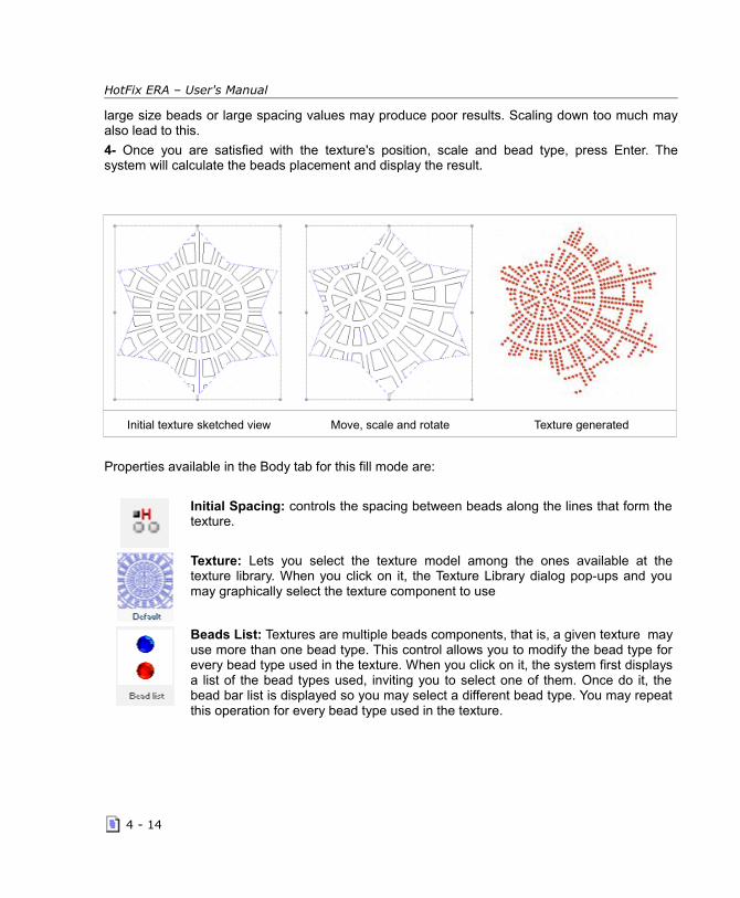
HotFix ERA – User's Manual
large size beads or large spacing values may produce poor results. Scaling down too much mayalso lead to this.
4- Once you are satisfied with the texture's position, scale and bead type, press Enter. Thesystem will calculate the beads placement and display the result.
Initial texture sketched view Move, scale and rotate Texture generated
Properties available in the Body tab for this fill mode are:
Initial Spacing: controls the spacing between beads along the lines that form thetexture.
Texture: Lets you select the texture model among the ones available at thetexture library. When you click on it, the Texture Library dialog pop-ups and youmay graphically select the texture component to use
Beads List: Textures are multiple beads components, that is, a given texture mayuse more than one bead type. This control allows you to modify the bead type forevery bead type used in the texture. When you click on it, the system first displaysa list of the bead types used, inviting you to select one of them. Once do it, thebead bar list is displayed so you may select a different bead type. You may repeatthis operation for every bead type used in the texture.
4 - 14

Creating Hotfix Designs
These properties may be also changed through theObject Inspector. Using it, you may also change thevertical and horizontal scale, position and rotation of thetexture. The Bead List group will display a row for everybead type used and, when you click on any of them, alist with your current bead bar contents will appear.
During edition, from the context menu, select Texture toenter the texture graphic edition mode (mouse drag tomove, scale and rotate).
Fill types with multiple-beads required a newconfigurable option to control the system behavior at themoment to use a component that includes a bead typethat is not currently within the bead bar.
Textures are designed using a given set of bead types. Although you may change them, you needto do it carefully, because some details of the textures may be lost if you, for example, use a beadsize much larger than the original. Also the distance among the different features within thetexture may become too close if you use very large bead types.
To make it simpler, the system, by default, will use the bead types predefined within the texture,adding them, if necessary, to your current bead bar.
You may control this behavior using theOptions and Preferences dialog. Use the treelist at the left and select Application > Project> Hotfix. Then, at the right panel, the checklabeled “Add beads to palette whennecessary” will let you control if the systemautomatically adds beads to bead bar(checked) or not. If you uncheck the option,the system will assign the first bead in yourcurrent bead bar to the bead type 1 in thetexture, the second to the bead type 2, and soon.
To change the existing texture of your design, just click on the Ellipsis button […] to open the“Select a Component” window, and choose another Texture.
Click on Texture, select one and press OK.
To access any texture quicker, add it to the Favorites tab, first select one of the available ones,and afterwards clicking on the yellow star. It will appear on your Favorites tab.
You can also click on any with the red padlock, and click on Buy Component to be able topurchase it and add it to your library of available textures.
4 - 15
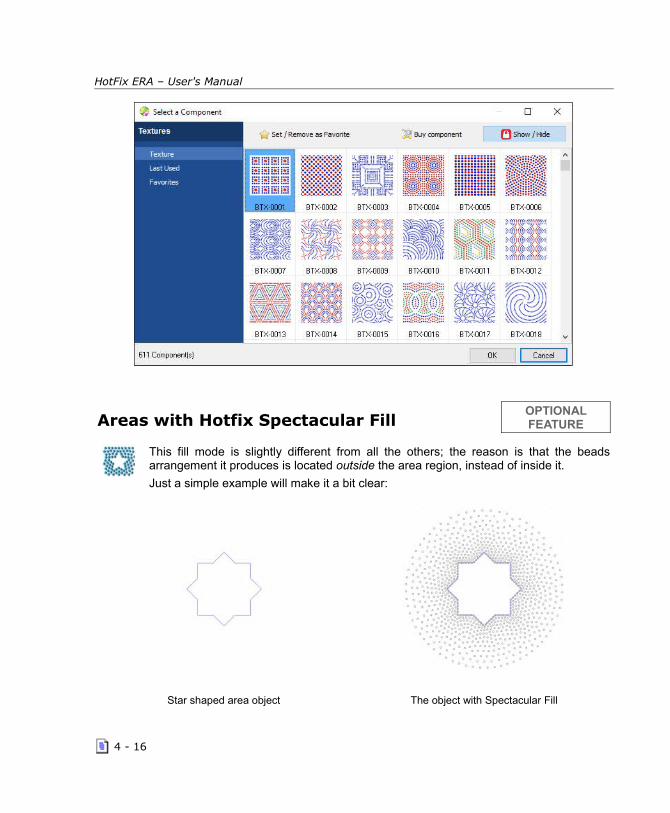
HotFix ERA – User's Manual
Areas with Hotfix Spectacular FillOPTIONALFEATURE
This fill mode is slightly different from all the others; the reason is that the beadsarrangement it produces is located outside the area region, instead of inside it.
Just a simple example will make it a bit clear:
Star shaped area object The object with Spectacular Fill
4 - 16

Creating Hotfix Designs
The Spectacular fill spreads beads, with variable density, around the defined object. How far thebeads are spread and the density variation used are easily and graphically controlled and also theshape of the “spreading pattern” may be selected among several shape options.
The basic steps to use Spectacular Fill are:
1- Within the Hotfix ribbon, select Single Hotfix Fill and then Area with Hoftfix - Spectacular Fill.The system displays the Hotfix Area-Body ribbon.
2- Create the area object as usual. Consider that this fill mode spreads beads outside the object,so check you have enough clearance around the object.
3- Once the area contour is completed, the system will create theeffect using the current density and shape values. Click on theSelect Object tool (or press F11) and the system will enter to editionmode for the object you have just created. Get the context menu(right click) and select Customize Spectacular Fill Density: thesystem will display a line with a square mark near the object center,a rectangular cursor at the middle and a triangle mark at end. Dragthe triangle mark to change the size of the shape effect, drag thesquare mark to change the effect shape center and slide the middlemark to change the average spacing position (see properties next).
These handles let you almost completely control the effect. To change the shape of the spreadingpattern, you need to use the Effect Shape control at the ribbon bar.
Take a look to the available properties. They are quite similar to the Variable Density fill mode:
Initial Spacing: controls beads spacing at the shape's center (square mark)
Final Spacing: controls beads spacing at the shape's outline (triangle mark)
Half Grading Point: Defines a point where spacing is the average valuebetween Initial and Final values. Position of this point is represented as a value inthe range 0.1 to 0.9, where 0.1 is located near Initial point and 0.9 is located nearFinal point.
Effect Shape: Defines the shape of the beads pattern. The shape will alwayssurround the object. The shape size is controlled graphically.
Curve: Creates a shape effect similar to the object shape
Circle: Creates a circular or elliptical shape
Rectangular: Creates a rectangular or square shape
Round Rectangle: Creates a round-rectangular or square shape
4 - 17

HotFix ERA – User's Manual
Areas with Hotfix Outer Ring FillOPTIONALFEATURE
In this fill mode, the system calculates a group of exterior rings and places the beadsalong them. The same as the inner ring fill, the special feature of the Variable Distancefill mode, is that you can control the separation between the rings, in a one by onebasis, allowing beads density gradients, to achieve incredible effects.
Ring fill mode is better suited for large area objects with small beads. This combination allowsthat several rings may be fitted outside the shape so the distance variation effect may becomeevident.The properties to control the Variable Distance fill mode (Body tab) are:
Beads Spacing: Controls the space between beads along all of the rings. A distance of0 (zero) means that beads are “touching” its neighbors. If bead type is sequin, a negativevalue, that produces some overlapping, is allowed.
Margin from Borders: Set a distance from the borderline where no beads are placed.
Pattern: This button displays the Rings Pattern dialog box. This tool lets you use any ofthe Radial Patterns included; or to edit them to create a new one.
The Rings Pattern box shows someRadial Pattern samples you can use.Click on the All option, select one andpress OK.
You can also edit any of them, changetheir configuration and use it right away. Itwill appear under the Custom option.
To access any Ring Pattern quicker, addit to the Favorites tab, first select one ofthe available ones, and afterwardsclicking on the yellow star. It will appearon your Favorites tab.
Choose any pattern, for example the one named RO11-001, press the Edit button to see thenumber of rings the pattern has, and a preview pane on the right.
4 - 18

Creating Hotfix Designs
The Rings control is set to 1 and the list contains just one row. You may define as many rings asyou want.
The Rings Pattern settings in the left picture was used to fill the heart design shown in theprevious page. Three rings were defined. The separation between them was increased from ringto ring to produce the vanishing effect. The red line in the Preview panel indicates the objectboundary. The black background region represents the object exterior.
Angle mode: Non round beads may be oriented, that is, place rotated(with respect to its center) at different angles. Orientation may be fixed (allbeads at the same angle) or may be variable, considering the pathdirection.
This property has three options that let you control beads orientation(from left to right):
Perpendicular: Beads are oriented following a variable directionperpendicular to the path.
Tangent: Beads are oriented considering a direction tangent to the path.
Fixed: This is the default option. All beads are placed at a the fixed angleindicated in Angle Value.
Beads angle: Set the rotation (around its center) angle of the beads. Useful for nonround pieces.
4 - 19

HotFix ERA – User's Manual
Ray Hotfix ColumnOPTIONALFEATURE
In this fill mode, the user defines a column type section, in which the system will placethe beads along a series of rays which are oriented parallel to the column's directions(defined by consecutive pair of nodes). You can control the separation between therays, and a random edge fill on them.
In a Column type section, the main reference is formed by guides. These are defined bysequenced pair of nodes, which establish directions within the column. These guides define boththe section’s geometry and the direction of the rays. A section of this type is formed at least by twopair of nodes.
The basic steps to use Ray Hotfix Column are:
1- Within the Hotfix ribbon, select Single Hotfix Fill and then RayHoftfix Column. The system displays the Hotfix Vector-Body ribbon.
2- Create the column object as usual, that is, insert at least twopairs of nodes that will work as directions.
3- Once the column has been completed, the system will create therays effect using the current ray type and separation values. Clickon the Select Object tool (or press F11) and the system will enter toedition mode for the object you have just created.
4- Open the Object Inspector to see the property values.
The properties to control the Ray Hotfix Column (Body tab) are:
Rays Density: You have two choices: Use Ray Separation or Use Ray Count.
4 - 20
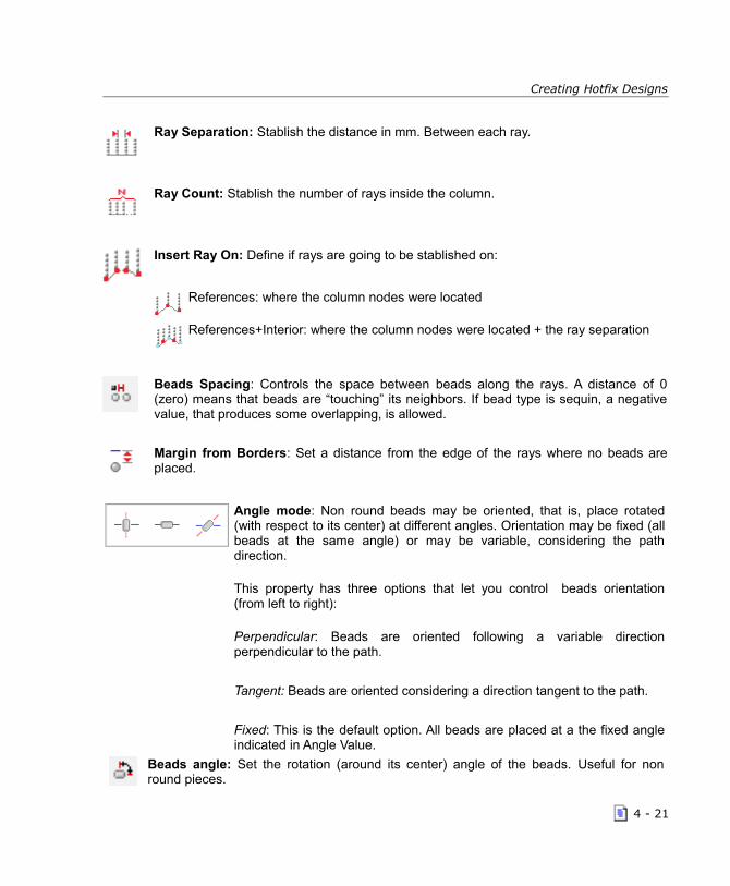
Creating Hotfix Designs
Ray Separation: Stablish the distance in mm. Between each ray.
Ray Count: Stablish the number of rays inside the column.
Insert Ray On: Define if rays are going to be stablished on:
References: where the column nodes were located
References+Interior: where the column nodes were located + the ray separation
Beads Spacing: Controls the space between beads along the rays. A distance of 0(zero) means that beads are “touching” its neighbors. If bead type is sequin, a negativevalue, that produces some overlapping, is allowed.
Margin from Borders: Set a distance from the edge of the rays where no beads areplaced.
Angle mode: Non round beads may be oriented, that is, place rotated(with respect to its center) at different angles. Orientation may be fixed (allbeads at the same angle) or may be variable, considering the pathdirection.
This property has three options that let you control beads orientation(from left to right):
Perpendicular: Beads are oriented following a variable directionperpendicular to the path.
Tangent: Beads are oriented considering a direction tangent to the path.
Fixed: This is the default option. All beads are placed at a the fixed angleindicated in Angle Value.
Beads angle: Set the rotation (around its center) angle of the beads. Useful for nonround pieces.
4 - 21

HotFix ERA – User's Manual
Random Edge: The beads may cover the ray path in a randomly way. You have threechoices:
Side A
Side B
Both Sides
Random Factor: Percentage of the complete ray that will be not filled completely withbeads, but randomly.
Path and Areas with Hotfix Assorted FillOPTIONALFEATURE
The software counts with a toolset for the creation ofHotFix objects, where the main fill rhinestones (orsequins) of several shapes, colors and sizes at the sametime..
These tools enlarge the diversity and variety of creative fills for the creation of HotFix designs.
These kind of fill styles may have limitations in some cases (with some geometric shapes). Theuser must check that the resulting objects match to the expected result. The user must also checkin detail when the used components are of different shapes and sizes, because the proximity ofthe component may produce undesirable results, even overlapping.
Manual Hotfix
This tool lets you insert one, isolated, hotfix piece anywhere in your design. Veryuseful to add some special pieces, sometimes large ones, normally used in very lowquantities, or to complete the placement generated by the system for a given object.
To add manual pieces, just activate the tool from the Hotfix ribbon, select a bead from the beadbar and click where you need to place it.
When the Manual Hotfix tool is active, the ribbon shows position, angle and bead type propertiesthat let you control, accurately, the bead placement.
4 - 22

Creating Hotfix Designs
Hotfix Texts
Texts are very powerful objects allowing you to easily create legends with hotfix pieces.
HotFix ERA lets you to create hotfix text using a set of detailed, pre-digitized fonts, and also usingthe TrueType ® fonts installed in your computer. HotFix ERA Text features include a completemanipulation of size, orientation, spacing (characters, words, lines) of texts and characters insidetexts, text layout effects (like arc, bridge, diamond, etc) and more.
Due to the extense possibilities text objects offer, we have prepared a special chapter, the nextone, totally dedicated to texts object.
Creating Hotfix objects
Producing a hotfix design, from the idea to the garment, basically involves:- Artwork: Some kind of drawing, sketch, image or good specification related with the art
behind the design.- Planning: You need to know the size of your design and what hotfix pieces will be used.
The knowledge about how the design will be transferred to the garment (machine, stencil,manual) may also help.
- Object Creation: As mentioned, this task known as “Digitizing” refers to the process toconvert the artwork into objects and set the properties that control the beads placement.
- Export the design: Once the design is finished, you need to produce some type of outputto move the design from the computer to the garment.
In this section we will focus on the Object Creation task or Digitizing. We will assume that anartwork image (of any type, unless specified) is displayed as screen background.
The chapter Images and Vectors contains detailed information about the HotFix ERA tools forworking with artwork files.
Manual Digitizing
The term Manual Digitizing means that objects creation isaccomplished by tracing the artwork shapes manually. You need toselect the proper creation tool (path and area basically) and place thenodes using the background image as reference and trying toreproduce the features of the shapes in the artwork.
Selecting the bead type you will use and setting the fill mode properties may be done before orduring creation or, after creation (edition). Usually, the basic settings are done during creation andthen adjusted (edited).This process is repeated for each shape in the artwork.
4 - 23
HotFix ERA – User's Manual
Assisted Digitizing: Autotrace
Autotrace is a time saving tool that automates the process of tracingthe artwork. Instead of manually placing the nodes to capture theshapes in the artwork, the system automatically detects them (basedon its color) and creates the objects reference for you.
To use this feature you just need to select Autotrace within the Digitizing Methods group, locatedon the left side of the path and area hotfix object ribbons. Autotrace is disabled if there is noimage loaded on the working area.
When used with raster images (pixel based images), the key for success is the image quality:
1- The minimum recommended image size is around 125 pixels per inch (5 pixels permillimeter). So, if your design has to measure 4” x 4”, the image size should be at least 500 x500 pixels.
2- Image colors have to be “solid” for proper recognition. Sometimes, a region that seems to belight blue is made of a mixture of blue and white pixels.
3- Shape borders should be well defined. Usually, the process of scaling an image, introducesan effect called blur that is not good for automatic recognition. A shape border in a goodimage is a clean edge with different colors at both sides, while in a blur-ed image you cannote a graded transition between colors. Shadows and light effects are also bad for automatictracing.
Take a look at a brief example about Autotrace usage. We will use a raster image called ASR-025included with the system and scaled to 5” (125 mm) wide.
Step 1 - Select creation tool
We will digitize the Indian face using an Area with Hotfix - Uniform Fill andRadial Fill initial layout . As the shape size is not so large, we will select asmall, 4 SS (1,7 mm.), round rhinestone crystal red.
Step 2- Select tracing mode
From the Digitizing Methods group, to the left side of the HotFix Area Bodyribbon, click on Auto to open the list of options, and click on Autotrace.When you move the mouse pointer into the working area, you’ll note aspecial mouse cursor.
4 - 24

Creating Hotfix Designs
Step 3 – Trace
Move the mouse pointer over the shape representing theindian face and click on it. The shape borderline will berecognized and will be surrounded by a flashing dashedline.
In the group Area Fill, check that the Bead spacing is set to1 mm and Margin to 0; and that Radial is set as initiallayout. Hit the enter key. The system will generate the requiredbeads placement to fill in the shape.
Step 4 – Continue creating.
Once the first object is created, the system will be ready for thenext one. Move the pointer to red shape above the face, click on itand hit enter. Repeat the process with all red shapes in the artwork.
Hide the image to check the result. To do it, just click on theword Auxiliar at the top-right of the working area.
During tracing, you have the chance to modify the recognizedregion before creating the object main reference. The contextmenu lets you expand and contract the recognized shape.
These tools are useful to create objects slightly smaller or largerthan the artwork shape. You can also remove small regions andinlets and smooth abrupt shape changes using the tool RemoveNarrow Regions.
4 - 25

HotFix ERA – User's Manual
Filtering example: Note how narrow inlets were removed by the filter.
Autotrace helps you creating one reference at a time. If the shape you are tracing has a hole,once you created the main reference, before hitting Enter, select Hole and then use the autotraceagain to capture the hole reference. Even more, you may switch to manual mode on the fly and,eventually, create the hole reference manually. After the hole has been traced, press Enter.
Automatic Digitizing: Auto Complete
Auto Complete is a full automatic digitizing tool. Although the procedure touse Auto Complete is almost identical to the Autotrace procedure, it createsall the object references at a time, that is, the main reference and thereferences for all holes the shape has.
Even more, Auto Complete lets you trace several shapes at a time, creating several objects, ofthe same type and fill mode: Once the first shape was traced, press and hold the Ctrl key andtrace another one. When you press Enter, the two objects will be created at the same time.
Digitizing using Geometric Shapes
Creating objects from Geometric shapes is another semi-automatic digitizingmethod. It helps you to create the object references (main reference and holes)from a library geometric shapes. They are available for path and area objects.
Using this tools is very simple. See the example next.
Creating a path with a geometric shape
Step 1 – Select the path tool and set the Digitizing Mode to manual. For this example, we willuse a round rhinestone with a diameter of 2 mm. (6ss), Aquamarine Color. Set Bead spacing to1 mm, Angle Type Fixed with Bead Angle value of 0 (zero) degrees. Set “Add Beads on” Path.
Step 2 - Click on Shapes. Within the gallery, scroll down to the categorynamed Advanced Shapes and select the shape named AAS_022 showed inthe right picture.
Move the pointer into the working area and drag the mouse. The shape willappear and will start to scale up following the mouse move. Set a sizearound 60 x 57,7 mm. You may press and hold down the Ctrl key to scale theshape proportionally.
4 - 26

Creating Hotfix Designs
Step 3 – Release the mouse button and hit Enter. Press Ctrl+F9 to generatethe beads. You have just created a path object with an aspect similar to theone showed in the picture on the right.
Editing Hotfix objects
Once created, modifying the hotfix objects is a very simple task. You just need to activate theSelect Object tool and click on the object you want to edit. HotFix ERA will highlight the object,display its nodes and refresh the ribbon, toolbars and other views to give you access to the objectproperties and geometric elements.
Selected objects are surrounded by a set of special handles that allow you to move, scale androtate it. Also, within the ribbon bar, appears a tab named Layout with alignment and repetitiontools among others.
Selecting the objects for editing is a topic by itself. The following paragraphs introduce theavailable selection tools.
Object Selection tools
The second button on the auxiliary toolbar, located above the working area, is the selection tool.Clicking on the button activates the powerful selection tool. Depending on how you use the tooland which controls you activate when you are making a selection, you get a different behavior andresults.
If you click on an object, it becomes selected.
If you click and drag left to right, the tool lets you select byrectangle. A shaded rectangular box, with one corner fixedat the position you start dragging and the opposite locatedin the current mouse pointer position, is displayed on thescreen. When you release the mouse buttons, all objectstotally inside the rectangle are selected.
If you click and drag right to left, the tool lets you select by“crossing rectangle”. In this mode, objects totally orpartially included in the rectangle are selected.If you press and hold the Ctrl key, a click on an objectadds it to the selection set. Once an object is added, anew click on it removes it from the selection set.
Clicking on the arrow pointing down, unfolds the selection menu, with extra selection tools.
4 - 27

HotFix ERA – User's Manual
Select by Rectangle: Is the default mode mentioned in the above paragraph.
Select by Outline: In this mode, you create, click by click, a free shaped outlinesurrounding the objects you need to select. Once did it, access the context menu andselect OK to instruct the system to select all objects included inside the defined outline.
Select All: Automatically selects all objects in the design
Invert Selection: Creates an inverted selection set, that is: all currently selected objectsare unselected and all currently unselected objects are selected.
Hotfix piece edition tool
This tool lets you modify an individual hotfix piece, no matter if the piece belongs to anobject filling or is a manual hotfix piece.
Once the tool is activated and a bead selected: Drag to move the piece. Press and hold Ctrl key to display the rotation handles. Drag them (always holding Ctrl) to
rotate the piece. Rotation center may be also dragged to move it where required. Press Delete key to remove the piece Press Shift key and drag to initiate an on the fly piece insertion. Click on the bead bar or use the beads gallery within the ribbon to change the bead type. You can also use the Position and Angle controls within the ribbon to accurately edit the bead.
Working with Hotfix Objects Blocks
Any time you use the selection tools, the resulting selection set (even if it contains just one object)is considered as an object block. As described previously on Object Selection Tools, you cancreate a block using any of the selection methods. Once created, HotFix ERA draws a dashedbox around the objects.
4 - 28

Creating Hotfix Designs
The box has eight grips or handles (in the corners and in the middle of each side).
Drag any corner handle to produce a proportional scaling of the block, keeping the oppositecorner in place.
Press and hold the Shift key and drag a corner handle to produce a proportional scaling butkeeping the block center in its place.
Drag any side handle to scale horizontally or vertically, keeping the opposite side in its place.
Press and hold the Shift key and drag any side handle to scale horizontally or vertically butkeeping the block center in its place.
Press and hold the Control key and drag the corners to rotate the block around the rotationcenter. Holding the Ctrl key you can also drag to move the rotation center where you need.
Scale proportional Non proportional scaling Rotate
Note: During these operations, a floating legend (called tooltip) with current size, size change and angle is displayed to help you to work more accurately.
When an object or block is selected, HotFix ERA activates the tab Layout within the ribbon (thistab is the default when the block contains multiple objects).
The Layout tab contains a set of tools specially prepared for block operations:
Scale and Shape group
Rescale: This tool lets you define a segment in the object and then indicateto system the size you need that segment to be. So, you can scale yourblock considering the size you need for an specific shape on it (the height ofa given shape, the diameter of a circle, etc)
4 - 29

HotFix ERA – User's Manual
Proceed this way:1- Define the block2- Activate the Rescale tool. Move the mouse pointer into the working area and click to set oneend of the reference segment and drag to set the end point.3- When the mouse button is released, the scale box will appear. The measured length of thedefined segment will be highlighted and ready to accept your input. Just enter the size you wantand press OK. The block will be scaled so as the segment you defined now measures the sizeyou entered.
Rotation Angle: This tool operates quite similar to rescale. Once activated the system waits youdefine a segment (click for start point and drag for end point ). Then, the rotation box appears withthe measured angle highlighted and ready for input. You just need to enter the desired angle andpress OK. The block will be rotated so as the defined segment has the entered angle. This tool isvery useful at the time of aligning a shape with the axes. Define the angle reference segmentaligned with the shape and then set the new angle to 0 or 90 degrees.
Rotate/Mirror : Simple tools that produce common fixed angle rotation (90, 180, 270 degrees)and mirrors (vertical and horizontal).
Position and Size Groups
This groups contain controls that let you set the position and size ofobject blocks accurately. Just enter the desired value in the boxes andpress enter.
Align Group
This group contains tools for aligning objects respect other objects inside theblock and the hole block respect to the design.
To Object: This tools aligns the objects inside the block to left, right, top and bottom, using asreference the leftmost, rightmost, upper and lower object of the block. You can also align theobjects center horizontally, vertically or both.
To Design: Contains tools for align the whole block with respect to the design, that is, with respectto all other objects not included in the block.
Center tool: Moves the center of the block to the system origin point (0,0).
4 - 30

Creating Hotfix Designs
Repetitions
Access the available commands from the Block – Layout ribbon. Inthe case of Hotfix design, you have only the Duplicate option.
Duplicate Block This command performs a copy and paste of the selected block in only one step. Italways works on the active document.
Effects on Hot fix objectsOPTIONAL FEATURE
HotFix ERA allows you to distort a block following complex geometricalpatterns by means of the so-called effects. In the next paragraphs you willfind a description of these effects and the instructions on how to use them.
Note: Remember that the undo-command is always available, in case you want to undo after having applied an effect to a block.
All the effects are available both from the ribbon BLOCK LAYOUT >Create Objects group > Effects on Hotfix Objects, and from thecontext menu.
The available effects are: Move Random; Color Random; ColorBlending; Hotfix from Grayscale; Hotfix from Photo Color; Whirl;Sphere and Grid Transformation.
Move Random OPTIONAL FEATURE
When applied to a block, some of the stones are displaced a distance that is configured from the Random Position Effect.
4 - 31

HotFix ERA – User's Manual
The result show how some of the stones havebeen moved with no specific direction, to add anirregular look on the design.
Color Random OPTIONAL FEATURE
When applied to a block, some of the stones are replaced with the ones you have specified from the Random HF Type Effect box.
The result shows how some of the stones have been replaced aleatorily with some of theselected from the Random HF Type effect box.
4 - 32

Creating Hotfix Designs
Color Blending OPTIONAL FEATURE
When applied to a block, the different color beads mix within the object. The amount ofbeads of each color depends on the relative location of the slider in the Effect box.
The result shows how part of the stones have been replaced aleatorily with the other selectedcolor from the Color Blending effect box.
Grayscale Photo Stone OPTIONAL FEATURE
You need to have a Hot Fix object and an a grayscale image below. When you apply thiseffect, the stones change their size following this premises: dark gray, uses a big size stone; intermediate gray uses an intermediate size stone; light gray uses a little stone.
Insert an image on the workarea. We used PSR-004.jpg available fromC:\Users\Public\Pictures\Sierra Technology\Artwork Photo or throughthe Catalog.
From the Hotfix ribbon, choose Area with HotFix - Flat Fill. To createthe area object, use the Round Rectangle from the Shapes item.
We used Beads and Rows spacing in 0,5 mm, Beads offset in 50%and a Jet Color 10ss Rhinestone Round.
4 - 33

HotFix ERA – User's Manual
Move the Area object you have justcreated over the image.
From the Hotfix Area Layout ribbon,Create Objects group, click onEffects on Hotfix Objects, andchoose HotFix from PhotoGrayscale.
The Gray Scale Photo Stone FX box will open. On the left pane it shows all the colors the imagehas. On the right pane, you will have all the beads defined on your system for this task. You haveto assign a bead to each color, to be able to use the Photo Stone tool. Proceed as follows:
On the right pane, click on a bead tobe used, then click on the color onthe left pane to be replaced and pressthe [<] button.
The selected bead will appear on theleft pane corresponding to the coloryou chose.
Repeat the operation will all theimage colors and press OK.
See the result on the right image.
You get a design similar to the image you used, but madeout of different size but same color stones, that aredisplaced in the same way the Fill mode you selected.
4 - 34

Creating Hotfix Designs
Color Photo Stone OPTIONAL FEATURE
You need to have a Hot Fix object and an a image below. When you apply this effect, the stones change their color to the one most similar to the color of the image on the background. The result is getting a design very similar to the image below.
Insert an image on the workarea. We used ASR-006.bmp availablefrom C:\Users\Public\Pictures\Sierra Technology\Artwork Bitmap orfrom the Catalog.
From the Hotfix ribbon, choose Area with Flexible Fill. To createthe area object, use the Round Rectangle from the Closed Shapesitem.
Next click on Add Direction, and insert a curve direction. PressEnter. You will get a result similar to the figure on the right.
Move the Area object you have justcreated over the image.
From the Hotfix Area Layout ribbon,Repetitions group, click on Effectson Hotfix Objects, and choosePhoto Stone.
The Color Photo Stone FX box will open. On the left pane it shows all the colors the image has.On the right pane, you will have all the beads defined on your system. You have to assign abead to each color, to be able to use the Color Photo Stone tool.
Proceed as follows:
On the right pane, click on a bead to be used, then click on the color on the left pane to bereplaced and press the [<] button. The selected bead will appear on the left pane correspondingto the color you chose.
Repeat the operation will all the colors and press OK.
4 - 35
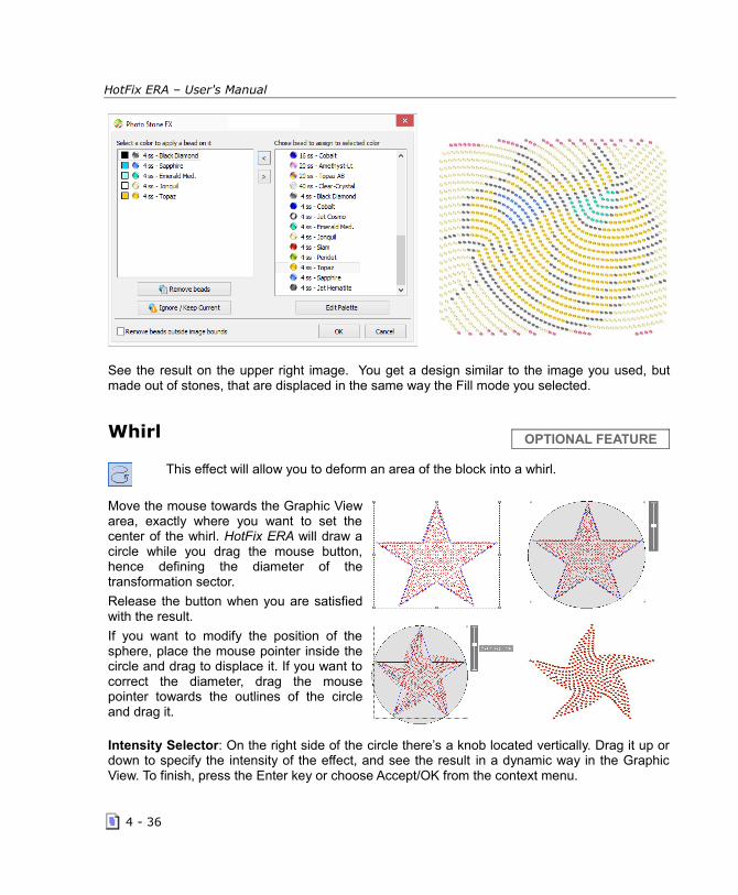
HotFix ERA – User's Manual
See the result on the upper right image. You get a design similar to the image you used, butmade out of stones, that are displaced in the same way the Fill mode you selected.
Whirl OPTIONAL FEATURE
This effect will allow you to deform an area of the block into a whirl.
Move the mouse towards the Graphic Viewarea, exactly where you want to set thecenter of the whirl. HotFix ERA will draw acircle while you drag the mouse button,hence defining the diameter of thetransformation sector.
Release the button when you are satisfiedwith the result.
If you want to modify the position of thesphere, place the mouse pointer inside thecircle and drag to displace it. If you want tocorrect the diameter, drag the mousepointer towards the outlines of the circleand drag it.
Intensity Selector: On the right side of the circle there’s a knob located vertically. Drag it up ordown to specify the intensity of the effect, and see the result in a dynamic way in the GraphicView. To finish, press the Enter key or choose Accept/OK from the context menu.
4 - 36

Creating Hotfix Designs
Sphere OPTIONAL FEATURE
This effect will allow you to deform the block, giving it a spherical shape. To use thiscommand follow the steps below:
The application over the block is similar to theWhirl effect, having to define the effectintensity from the control slider. Click insidethe design area and drag the mouse pointer todetermine the area to apply the effect; youcan move it or change its size.
Apply the desired intensity from the rightcontrol slider.When you are satisfied with the result, openthe context menu and click on Accept / OK, orsimply press the Enter key.
Grid Transformation OPTIONAL FEATURE
This effect allows you to place the block on a rectangular grid. To form this grid, open thecontext menu and add or delete rows or columns (next figure left), according to the resultyou want to obtain. The rows and columns entered will be arranged along or across theblock, forming a grid.
Moving the grid’s points with the mouse (the intersection between rows and columns) youdeform it, while the block beads follow that transformation (next figure right).
4 - 37

HotFix ERA – User's Manual
Drag the grid’s points to obtain the desired shape, as you proceed deforming the grid, HotFix ERAwill calculate the beads location, showing the result on the Graphic View. To finish, open thecontext menu again and click on the option Accept / OK, or simply press the Enter key.
Object Manager and Object InspectorThe Object Manager is a special, technical view, that displays a “map” of your designs,showing all the objects it contains: vector images, raster images and hotfix objects.Access it Object Manager by clicking on its tab, to the right of the working area: A groupwith two panels will open: the Document Map at the top and the Object Inspector at thebottom. Object Manager is an important tool to check what objects the design has and it’s also amethod to select objects while Object Inspector is a detailed object’s properties editor.
Object Manager
The Object Manager (OM) is a special type of list known as a“tree list”, much similar to the one used to display disk units,folders, sub-folders and files.
The main items (the “parent” items, using the tree list language)are the basic object types.
Hotfix ERA works with: Images, Vectors and Hotfix objects.Inside them, a list of items (the “child” items) represent theloaded images, vector artwork objects and hotfix objectsrespectively.
Selecting any child item within OM, produces the synchronized selection of the object itrepresents within the graphic view and, vice-versa, selecting an object within the graphic view,selects the corresponding item within the OM.
Object selection is just one of many operations available from the OM: You can copy, paste, anddelete objects one by one or by blocks:
Hold the Ctrl key and click items to create multiple selection sets;
Click an item, hold the Shift key and click a second one to select all items between themin the list.
Drag items (within the same parent group) to re-arrange their order within the sequence(remember that object sequence may be meaningless for rhinestones, rhinestuds andnailheads but may be important for sequins and spangles and also for vector objects).The icons beside each parent group let you Block and Hide that object type: Blockingan object type makes impossible to select, delete or modify any object of that type;
4 - 38

Creating Hotfix Designs
hidding an object type makes that type invisible.
Object Inspector
The Object Inspector is a complete browser and editorfor object’s filling properties.
It's organized as a categorized list with items arranged inrows. Each row controls a property.
For hotfix Area objects, Object Inspector (OI) displaysseparated tabs for body and borderline fills; for pathobjects, just the borderline tab is displayed
Rows in OI consist in two columns: one with the property name and icon and one with theproperty value. Clicking the property value activates the property editor to modify the value. Onceactivated, properties may display:
A down arrow to select the value among fixed options.A spin button to increase/decrease value or type in directly.
Sorting piecesA common practice when creating a design, is to proceed shape byshape, building the required objects without paying attention to the beadtype each object use. So, the resulting design sequence, that is, theorder of the objects as shown in the Document Map, follows exactly thecreation order. Due this, the design sequence is normally unordered interms of bead type, that is, not all the object using a given bead typeare placed one after another.
Sort Hotfix tool is designed to help you easily manage the design sequence, allowing automatic ormanually controlled object sorting.
The tool dialog is basically a list with items representing anobject or a group of contiguous objects that use the samebead type. The item shows also the bead type it uses, itscurrent position within the design sequence, the objectnumbers it represents and a tiny icon of them.
The tool offers two modes: Sort by Palette Order (Automatic), that sorts the objects according tothe bead types they use by following the bead bar order (objects using bead #1 first, then objectsusing bead #2, and so on) and Manually, that allows you to order the items as you want.
4 - 39

HotFix ERA – User's Manual
In manual mode, you may select any item and use the cursor keys to navigate through the list.The arrow buttons at the top right allows you to move the item within the design sequence (youmay also use drag and drop to do it).
Once two object that use the same bead type are set contiguous, next time you open the SortHotfix dialog they will be shown grouped into a single item.
Cleaning overlapped piecesMost materials used in garment decoration with hotfix beads do not allow overlapped pieces. Theexception to this rule are the sequin beads type, enough thin and flat to allow overlap.Rhinestones, rhinestuds and nailheads instead, are too thick and curve to allow overlap.
When objects are overlapped, totally orpartially, beads calculated for them areprobably overlapped too. The system will notdisplay any warning about this situation untilyou try to export the design using any of theoutput formats. At that moment a messagewill notify you that the design has overlappedpieces.
HotFix ERA includes a tool to automatically cleans overlapped piecescalled Hotfix Conflict Window. To launch the tool, you need to use thebutton located in the Hotfix ribbon > Finishing Tools group. This toolrequires you know some details about your design, basically, the orderof the objects in the design sequence.
When objects A and B are overlapped, one of them, let’s suppose A, is over B. This implies theidea of object‘s sequence: A over B is different than B over A. Most of the time this situationdoesn’t care for hotfix designs, however, it cares when overlap conflict exists and when you useoverlapped sequins.
The object sequence is visible with the Object Manager view: the top most object in the list isthe first object created and the rest of them are over it . So, the rule is: All the objectsfollowing a given one are over it.
The Conflict Window contains a tree list where each main item represents a conflict betweentwo objects and the items description declares what object is over what other. If you expand thetree to explore the sub-list associated to each main object, you’ll find the overlapped beads,one by one. The check marks at the left of the items let you include/exclude them fromcleaning.
4 - 40

Creating Hotfix Designs
At the same time, the graphic view shows redcrosses for each bead in conflict that arechecked in the list. The toolbar at the top ofthe box lets you Clean, Refresh the list,Check all items, Uncheck all Items, Expand alllist and Collapse all list (mentioned in orderfrom left to right).Check the conflicts you want to solve andpress the Clean button.
The system will remove the beads in conflict from the back object, preserving the beads ofthe front object.
When all conflicts were solved or when there is no conflicts in the design, the Conflict List willappear empty.
Importing YNG files OPTIONALFEATURE
This feature allows you to read hotfix YNG files produced with GemMaster ® version2.9 and import the beads information into a DSG design file. This function importsonly bead information (position, type and color). Design objects you may havecreated are not imported.
To import YNG files, go to the File>Openribbon, and from Import group, click on A HotfixFile.
A standard File Open dialog appears. SelectYNG Files (*.yng) from file type.
Navigate through your units and folders, pointthe desired YNG file and press Open.
Reading YNG files may take some time (aprogress bar is displayed during this phase).
Once finished, the YNG Import file dialog will be presented. This dialog allows you to definewhich bead type, from the system's Beads Catalog, should be used for each bead type used inthe YNG file.
4 - 41

HotFix ERA – User's Manual
There are two lists: The one at the left (Bead assignment) shows the bead types found inside theYNG file, while the one at the right shows your current bead palette.
Two buttons at the top region of the box allow you to assign beads automatically:
Add to Palette: The system will search the Beads Catalog for beads that best match in size andcolor to the beads used in the YNG file. Once found, beads will be assigned to the importeddesign and they will be added to the current bead palette.
This mode keeps your current bead palette items, so it is recommended if you are importing aYNG file into an existing design (so you will get a merged design). The bead palette will contain allthe bead types it previously contains plus the bead types used by the YNG file. If your palettealready contains a bead type used by the YNG file, the existing one will be used (no duplicates).
Create New Palette: The system will search the Beads Catalog for beads that best match in sizeand color to the beads used in the YNG file. Once found, a new bead palette with them will becreated (your current palette will be lost) and its beads will be assigned to the imported design .
This mode is recommended if you are importing a YNG file into an new, empty design . The beadpalette will contain just the bead types used by the YNG file
Finally, you may also assign beads manually. Just select a row in the list at the left, and, using thelist at the right, click the green arrow to assign that bead to the imported design.
The Edit button at the top of the Current Bead Palette list allows you to modify your current paletteto best suite the assignment needs.
Once you have completed the bead assignment task, press the OK button.
4 - 42

Creating Hotfix Designs
The YNG design will be loaded into your working area.
Beads will be imported as Manual Hotfix objects, grouped by sequences of the same bead type,according to the bead order found in the YNG file.
This arrangement facilitates bead type edition, scaling, etc.
Importing PLT files OPTIONALFEATURE
This feature allows you to read the hotfix files created in other applications andstored in HPGL (PLT extension) as rhinestone stencils and import the information asa design file DSG. The function imports only position information, size and color ofthe holes. Design objects are not imported because the HPGL doesn’t include suchinformation.
To import PLT files, go to the Hotfix ribbon >Insert Hotfix Objects Group > Insert to openmenu, and click on Insert a Stencil File.
A standard File Open dialog appears.
Navigate through your units and folders, pointthe desired PLT file and press Open.
Reading PLT files can take some time (thesystem displays a progress bar during thisstage). After reading, the PLT File Import dialogbox is shown.
Reading PLT files can take some time (the system displays a progress bar during this stage). Afterreading, the PLT File Import dialog box is shown. This box allows you to define what kind ofpieces (from the system catalog) is assigned to each part of the PLT file.
This box allows you to define what kind ofpieces (from the system catalog) isassigned to each part of the PLT file.
The box contains two lists: The left list ofbeads assignment, which shows thedifferent types of parts found in the PLTfile and the right list, the current hotfixpalette.
You can assign beads types manually. Todo this, select a row in the list on the leftand click on the green arrow in the list onthe right for the part you want to assign.The Edit button lets you adjust the paletteadding the parts you might need.
4 - 43

HotFix ERA – User's Manual
Once you have completed the bead assignment task, press the OK button.
The parts will be imported as manual hotfix objects, grouped by type of beads, according to theorder found in the PLT file. This structure facilitates subsequent type editing, scaling, etc.
Importing DST files OPTIONALFEATURE
This feature allows you to read the hotfix files created in other applications andstored in DST (DST extension) as rhinestone stencils and import the information as adesign file DSG. The function imports bead quantity information, size and color ofthe holes. Design objects are not imported because the DST doesn’t include suchinformation.
To import DST files, go to the File>Openribbon, and from Import Group, click on AHotfix File.
A standard File Open dialog appears. SelectDST Files (*.dst) from file type.
Navigate through your units and folders, pointthe desired DST file and press Open.
After reading, the DST File Import dialog box isshown.
This box allows you to define what kind ofpieces (from the system catalog) isassigned to each part of the DST file.
The box contains two lists: The left list ofbeads assignment, which shows thedifferent types of parts found in the PLTfile and the right list, the current hotfixpalette.
You can assign beads types manually. Todo this, select a row in the list on the leftand click on the green arrow in the list onthe right for the part you want to assign.The Edit button lets you adjust the paletteadding the parts you might need.
The parts will be imported as manual hotfix objects, grouped by type of beads, according to theorder found in the DST file. This structure facilitates subsequent type editing, scaling, etc.
4 - 44

Chapter 5
Hotfix Texts
Con ten t s :Hotfix Text.....................................................................................................2
HotFix ERA Text Objects.......................................................................2
Text object types.............................................................................2Creating Texts: Text ribbon..................................................................3
Example: Creating simple text in 3 steps.............................................3Editing Texts......................................................................................5
Editing Text Properties......................................................................5Editing Text Geometry......................................................................6
Text Transformations...........................................................................6
Transformation types.......................................................................7Using Transformations......................................................................7
Exploding Texts (Split Hotfix)..............................................................10
Assemble Hotfix Beads.......................................................................11
Disassemble Hotfix Object..................................................................12

HotFix ERA – User's Manual
Hotfix Text
This tool lets you create a hot fix object based on text characters using a library of predefinedfonts or the TrueType fonts you may have installed in your computer.
Texts are very powerful objects. This chapter will introduce the extensive list of featuresavailable in Hotfix ERA texts.
HotFix ERA Text Objects
When you create a path or area, you build the object shape using any of the creation methods:manual, assisted, etc. Shapes for Text objects, instead, are built from characters you type, with noneed for graphic input: you just need to select the font, set the size (usually the text height) and fillmode, and type the characters: HotFix ERA creates shapes for each letter and applies thespecified fill mode to them.
Text object types
There are two basic text types: those based on digitized fonts and those based on TrueTypefonts.
Digitized fonts: Are quality pre-built fonts, included with the system. These type of fonts werecreated, character by character, using special groups of basic objects (generally paths) and testedfor a range of sizes and bead types. When you create a text using a predigitized font, the systemuses those pre-built basic objects to generate the placement of beads.
TrueType fonts: Text based on TrueType fonts are built “on the fly”, using the shapes containedin the font to automatically create objects for each character you type. Then, all objects createdfor a given text are packed properly to allow easy manipulation and edition. It’s important to knowthat not all TrueType fonts have the same quality, and not all of them are suitable for hotfix.Proper selection of text size (basically, related with the bead type you will use) is the key forgetting good results.
5 - 2

Hotfix Texts
Creating Texts: Text ribbon
The Text ribbon contains most of the commands and properties you will use to create your hotfixtext objects. The following paragraphs contain a brief description of them, group by group.Font : This group contains controls to select the font type (digitized or TrueType), the font itselfand the text height. For TrueType fonts, you can also select the font style: Bold and Italic.Text: Inside this group you will find the box where you will type your text characters, the charactertable (especially useful for digitized fonts, to know what characters are available in the currentlyselected font), the alignment options (for multi-line texts), and the spell checker. For TrueTypefonts you may also activate the preview mode, forcing the system to display the typed charactersusing the selected font, instead of the default one.Spacing: This group includes controls to manage text spacing among letters, words and lines.Body Fill – Border Fill: These groups controls the fill mode of the text object. Depending uponthe selected font, both groups or just one of them will be displayed. Usually, both groups arepresented for TrueType fonts and just one, Border Fill is displayed for digitized fonts.Arrange: This group contains the commands to change the text layout, allowing you to arrange itfollowing simple layouts like arc (upper, lower or both for multi-line texts), stair, etc. or moreelaborated templates like bridge, diamond, etc.
Example: Creating simple text in 3 stepsIn this example, we will create a 40 mm height hotfix text with the word “Sierra” using the digitizedfont Blockletter and a golden rhinestud, 2 mm. diameter. See the procedure below as a basicguide for creating texts:
Step 1- Select the font and text height
In the Font group, click Digitized Font. Then, click the Font button to open the font galleryand select the font named Blockletter.Click the height control and type in 40 if you areusing Metric system or 1.6 if you are using Imperialsystem.
The system includes a standard pack with 10digitized fonts. Additional fonts may be available atspecial prices upon request.
5 - 3

HotFix ERA – User's Manual
Step 2- Set fill mode properties
The font we have selected is based on pathobjects. Due to this fact, the system displays aBorder Fill group with the same fill mode propertiesyou find in a path object.
Set bead spacing to 0.5 mm and select a goldrhinestud 6ss (2 mm. diameter).
Step 3- Enter the text
Using the box in the Text group, type in the word “Sierra” (withupper and lower case letters). The system will play an error beepsound if the character you are typing is not available in theselected font.
You may also use the Character table button to check what characters are available.Alignment controls will be enabled if the text has more than 1 line. To enter multi-line texts youneed to press “Ctrl + Enter” key combination to move the text cursor to a new line.When you finish typing, press Enter. HotFix ERA will create the object text, displays it within theworking area. A box will surround the text leaving it ready for edition.
The handles on the letters and around the text let you change the text position, size and rotation(use Ctrl to rotate) and letters size, position and spacing, graphically, by just dragging them.
5 - 4

Hotfix Texts
Editing Texts
One of the most useful features of text objects features is the persistence: Once a text object iscreated it is preserved with all its properties and you may edit the font, size, words, fill mode, beadtype, size, position, etc.Anytime you select a text object, HotFix ERA highlights it, shows the text handles and displays thetext ribbon, allowing edition of text properties and geometric aspect.
Editing Text PropertiesThe text ribbon is the main tool to edit text properties. Any property displayed there may bechanged and the object in the graphic view will immediately reflect that change.Using the Font group you may edit the font, style and height; using the Text group you maychange the letters and alignment; the Spacing group lets you modify the characters, words andlines spacing; the Fill mode group (Body, Border or both of them) allows edition of bead type andfill style and finally, the Arrange group, allows changes in text layout and effects.The Object Inspector may be also used to edit the fill mode properties.
The Text dialogue-box
At the bottom right corner of the Text group you may note a small icon. Clickingon it displays a dialog box with text properties related with the font andcharacters.
The box contains pictures that clearly show the meaning of many of the textproperties.
5 - 5

HotFix ERA – User's Manual
Editing Text Geometry
As mentioned, when you select a text object, HotFix ERA displays a box and a set of handles oneach letter and around the text.
Most of the handles around the text boxoperate in the same way that the handlesaround any other object: dragging thecorner handles scales the objectproportionally, keeping the opposite cornerin place and dragging the handles locatedat the middle of the sides, scale the objecthorizontally or vertically, keeping theopposite side in place.
If you hold the shift key while dragging, the position of the object center is kept, and if you hold theCtrl key, you may rotate the object and/or change the position of the rotation center.
Text objects have an additional handle located on the right side, between the lower and middlehandles, called the spacing handle. Dragging it you may proportionally scale the letters and wordsspacing.
Handles on letters allow control of letter size and position in aper-letter basis.
Dragging the handle near the letter baseline (a) moves the letterhorizontally; the middle handle (b) moves the letter vertically andthe corner handle (c) scales the letter.
In the example, letter “r” was scaled up using the corner handleand move a bit up with middle handle.
Text Transformations
In the previous section a simple geometry edition tool was presented that basically allows you toscale and rotate texts.
This section introduces tools that let you produce more flexible geometry manipulation: they arethe text transformation types.
5 - 6

Hotfix Texts
Transformation typesHotFix ERA allows two basic types of text transformation:
Envelope Transformations: Are based on the distortion of the box that contains the text.For example, bending the box containing the text produces an arc layout. Charactersare distorted according to the envelope distortion.
Line Transformations: Are based on the distortion of the line where characters lie. Forexample, tipping the baseline produces a stair layout. Characters are not distorted; justtheir position is modified.
In addition to this classification, HotFix ERA organizes the transformation in two groups: Defaultsand Templates. You can access them from the Arrange group.
Default transformations are simple, basic transformations likeRotation, Irregular, Arc (upper and lower) and Stair. Using thedefault transformations you may build envelope and linedistortions with any shape.
Templates: Although using the default transformations you maycreate transformations of any shape, the system includes a setof pre-built shapes, so you don’t have to do it by yourself. Theyare called Templates. Shapes like Bridge, Panoramic, etc. areincluded within the templates.
Using TransformationsAll transformations have a number of handles or grips to control them. Depending upon thetransformation, the system displays different handles that produce different effects. The followingexamples describes the behavior of the handles of some default transformations.
Stair (Step Text)
Stair transformation has three basic handles located atthe right side of the text.
Handle A controls the angle of the baseline. Drag it downto get a descending stair; drag it up to get an ascendingone.
Handle B changes text spacing proportionally.
Handle C produces a proportional scaling.
When you move the mouse out of the handles, a fourarrows pointer shape indicates that you may drag tomove the whole text.
5 - 7

HotFix ERA – User's Manual
Upper Arc
Lets you bend the text in an arc shape. The handles to control this transformation are:
Handle A: controls the verticalsize of the transformation box,keeping the superior arc inplace and moving the lowerone.
Handle B: Controls the horizontalsize of the box, but preserving the arcshape.
Handle C: Controls thedistance of the box from thearc center.
Handle D: Also controls the vertical size of the box, but it preserves the lower arc and move theupper one.
Handle E: Scales the whole box, combining the effects of handles B and D.
Handle F: Rotates the box around the arc center.
Handle G: Controls the arc radius.
Lower Arc
Lets you bend the text in an arc shape. The handles to control this transformation are:
Handle A: controls the vertical sizeof the transformation box, keepingthe lower arc in place and movingthe upper one.Handle B: Controls the horizontalsize of the box, but preserving the arcshape.Handle C: Controls the distance ofthe box from the arc center.
Handle D: Also controls the vertical size of the box, but it preserves the upper arc and move thelower one.
Handle E: Scales the whole box, combining the effects of handles B and D.
Handle F: Rotates the box around the arc center.
Handle G: Controls the arc radius.
5 - 8

Hotfix Texts
Irregular Box
Allows free distortion, with no predefined geometric shape. When you select this transformation,the system activates handles at the corners and at middle point of the sides.
Handles in this transformation have three states: free,straight and curve.
State may be changed right away by clicking on themwith the mouse right button.
Changing handles state allow you to get different boxdistortions, like the one showed in the picture above.
User line and User Distortion
These transformations are available at the time of creating the text object only. When you edit apreviously created text, none of them are available.To use these transformations, you need to select them after typing the text but before pressingEnter, from the Arrange group of options.
The User Line, allows you to freely create thebaseline where text characters lies. Each click setsa straight node of the baseline; Shift + click, sets acurve node. The backspace key deletes the lastnode. Hit Enter to finish baseline definition.
HotFix ERA will create the text placing the characters along the baseline created.
The User Distortion lets you create two lines, oneat the base and one at the top, using the sameprocedure that the one for User Line. Both linesdefine a box used to distort the text. The first lineyou enter will be the box base line. Hit enter tocontinue with the box top line and hit Enter again tofinish.
NOTE: top and bottom line nodes must be insertedfrom left to right.
5 - 9

HotFix ERA – User's Manual
Exploding Texts (Split Hotfix)
The term Exploding is used to make reference to the action of converting text objects into itsprimitive basic objects: paths and areas.
Once a text object is exploded, edition as text is no more possible but, you get total control overthe shapes and properties of the objects used to build the text characters.
To explode a Hot Fix text object:
1- Select the text.
2- Access the context menu and select Split Hotfix Text command.
Now that you have exploded the hotfix text, you can edit the paths and areas, to be able to addnodes, modify shapes, and change beads size and color, among other things.
5 - 10
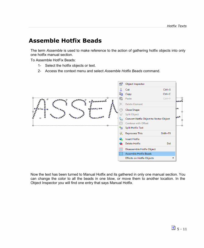
Hotfix Texts
Assemble Hotfix Beads
The term Assemble is used to make reference to the action of gathering hotfix objects into onlyone hotfix manual section.
To Assemble HotFix Beads:
1- Select the hotfix objects or text.
2- Access the context menu and select Assemble Hotfix Beads command.
Now the text has been turned to Manual Hotfix and its gathered in only one manual section. Youcan change the color to all the beads in one blow, or move them to another location. In theObject Inspector you will find one entry that says Manual Hotfix.
5 - 11

HotFix ERA – User's Manual
Disassemble Hotfix Object
The term Disassemble is used to make reference to the action of separating a hotfix object, textor assembled hotfix beads into separated hotfix manual beads.
It's very useful when you need to have one or several colors and to avoid havong to change thecolor to each bead, one by one.
Once you have all the manual beads, you can make one or several blocks of manual beads.Now you can select each block, press Assemble Hotfix beads, and the result will be that thisblock of manual beads, will be gathered into only one Manual Hotfix entity. Then you canchange the bead size or color to it and/or move it.
To Disassemble HotFix Objects:
1- Select the hotfix objects or text (first apply the Divide Text command).
2- Access the context menu and select Disassemble Hotfix Objects command.
Now the object has beenturned into a lot of ManualHotfix pieces.
You can select a block andAssemble them as one tobe able to move it or changeits color.
We assembled the beads,that make the letters V, Eand R, and then we havechanged the color and thestone. We assembled twomore groups.
See them in the document map. We have applied a rotation to the middle assembly.
5 - 12
Chapter 6
Hotfix Output
Con ten t s :Hotfix ERA Outputs..............................................................................2
File Formats....................................................................................3Send to machines and devices...........................................................4Printing..........................................................................................5
Exporting Hotfix files...........................................................................5
Machine Brands and Models Supported...............................................6Hotfix Exporter................................................................................7
Exporting to HPGL, Metafile and DXF Files...............................................9
Export to HPGL File..........................................................................9Export to Windows Metafile and DXF formats.....................................11
Sending Hotfix to machines and devices...............................................12
Sending information to CAMS machines.............................................13Sending information to Windows Cutters...........................................14Sending information to HPGL compatible devices................................16Sending information to Engravers.....................................................18

HotFix ERA – User's Manual
At the time to set a hotfix design on a garment, you will need to use any of the known hotfixtechnique methods. From the manual method to the automatic setting machines, you will need toget information about the beads type and position for your design. At this point, the output formatsbecome very important.
This chapter is dedicated to the output methods available in HotFix ERA. Basically, there areoutputs for stones, outputs for sequins and outputs for spangles. In case of stones, some outputsare prepared for direct to garment technique and others for transfer technique. The system is alsoable to send information to CAMS automatic settling machines (connected to the computerthrough serial port), to most Windows compatible vinyl cutters (those that have an standardWindows driver) and to HPGL compatible cutters with serial port interface.
Please note that most of the output methods are optional features. Your system may have one ortwo of them activated but not all of them.
Hotfix ERA Outputs OPTIONALFEATURE
The following tables lists all the output modes available. Output formats based on files; and theones related with direct connection to machines or devices are obtained using the File ribbon >Save - Export group > Hotfix → Export As...
6 – 2

Hotfix Output
You can also output your design from the Hotfix ribbon > Export group...
File FormatsThe file exported by the system should be transported to the machine using the available method(USB pen drives, disk, etc) as specified by the manufacturer.Stones:
Output Format Intended for
Hotfix Stone file for CAMS® SRT file format for CAMS® stone machines. File should betransported using the pen drive interface (*)
Hotfix Stone file for GemFix ® TJC file format for GemFix ® stone setting machines (*)
Hotfix Stone file for N&H ® ASC file format for N&H ® stone setting machines (*)
Hotfix Stone file for Salli ® SHF file format for Salli ® stone setting machines (*)
Hotfix Stone file for NCK ® DST file format for NC Korea ® stone setting machines (*)
Hotfix HPGL File PLT file with standard HPGL format for use with cutters andmilling machines to create stencils. May require some post-processing with machine specific software.
The term Stone is used to refer to Rhinestones and other type of hotfix pieces the machines maysupport like rhinestuds and nailheads.Sequins:
Output Format Intended for
Hotfix Sequin file for Salli ® DST file format for Salli CSM® sequin setting machines. (*)
Hotfix Sequin File for SWF® DST file format for SWF-M® sequin setting machines. (*)
Hotfix Sequin File for NCK® DST file format for NC Korea® sequin setting machines. (*)
Spangles:
Output Format Intended for
Hotfix Spangle file for NH® ASC file format for N&H ® spangle setting machines.(*)
Hotfix Spangle file for Coldesi DST file format for Coldesi spangle setting machines.(*)
6 - 3

HotFix ERA – User's Manual
Hotfix Spangle file for Technics ASP DST file format for Technics ASP spangle settingmachines.(*)
All hotfix types:
Output Format Intended for
Hotfix Windows Metafile EMF file format with filled shapes for all hotfix type piecescontained in the design. This format may be imported withgraphic software like Adobe Ilustrator, CorelDraw, etc.
Hotfix DXF file DXF standard format with the shapes for all hotfix type piecescontained in the design. This is a popular interchange formatused in CAD systems and also in some CNC and millingmachines.
Hotfix SVG File SVG file format with filled shapes for all hotfix type piecescontained in the design. This format may be imported withgraphic software like Adobe Ilustrator, CorelDraw, etc.
(*) Format suitable for most models. Please, ask your dealer for a sample file to checkcompatibility with your specific machine.
Mentioned brands and trademarks belong to their respective owners.
Send to machines and devices
Output Format Intended for
Send To CAMS® Sends hotfix stone design data to CAMS® machinesconnected to the computer through the serial port.
Send To Windows Cutter Sends hotfix stone contours information to Windowscompatible vinyl cutters to create stencils. Usually, a softwaredriver provided by the device manufacturer is required.
Send To HPGL Serial Device Sends hotfix stone contours information to any standardHPGL compatible device connected to the computer throughthe serial port.
Send to Engraver Sends hotfix stone contours information to WindowsCompatible engravers connected to the computer.
Send to Technics ASP® Sends hotfix sequin design data to Technics ASP® machinesconnected to the computer through the serial port.
6 – 4

Hotfix Output
Printing
Standard printing to any Windows compatible printer is also available. This output type may beused for reference, for manual beads placement and for customer presentations.
Exporting Hotfix files
The commands to export stone files to the different formats are accessed through the the Fileribbon > Save > Export > Export As... > Export/Send HotFix File or from the Hotfix ribbon > Exportgroup > Export Hotfix to machine.
Remember that Output Formats are optional plugins, so the list maycontain just one or two formats depending on what formats you havepurchased.
A dialog box named HOTFIX EXPORTER will open.
The following sections contain details about this box.
6 - 5

HotFix ERA – User's Manual
Machine Brands and Models Supported
Machine Brand Machine Model
Coldesi Spangle (DST) Spangle Elite
DS-Tech Stone RSM (MACH) DS-400-6C
GemFix Stone (MACH) GEM4023 / 3040 / 5550-2/2 / 5550-4/2
Generic Machine (DST) Generic 400
Nagel & Hermann Spangle LIBERO (MACH) Sequin Libero
Nagel & Hermann Stone ALLOVER (MACH) Allover 059 / 1600 / 3200
Nagel & Hermann Stone LIBERO (MACH) Libero Basic/Sheet/R/A/B/C/C8
NCK® Sequin DECOS (DST) DECOS S42-4C (400x400) / DECOS S42-4C(400x480) / DECOS S42-M4C / DECOS S42-M6C
NCK® Sequin DECOS (MACH) DECOS S42-4C (400x400) / DECOS S42-4C(400x480) / DECOS S42-M4C / DECOS S42-M6C
NCK® Stone DECOR (DST) DECOR S40V-1H4C (400x400) / DECOR S40V-1H4C(400x480) / DECOR S40V-2H6C (400x400) / DECORS40V-2H6C (400x480) / DECOR S30V-1H2C
NCK® Stone DECOR (MACH) DECOR S40V-1H4C (400x400) / DECOR S40V-1H4C(400x480) / DECOR S40V-2H6C (400x400) / DECORS40V-2H6C (400x480) / DECOR S30V-1H2C
Salli Stone ASM (DST) Salli ASM-6C-01H
Salli Stone ASM (MACH) Salli ASM-6C-01H
SWF Sequin SERIE-M (DST) SWF Sequin
Technics Spangle ASP (DST) ASP-Compact / 645-2 / 645-4
Technics Spangle ASP (MACH) ASP-Compact / 645-2 / 645-4
Technics Stone (DST) Combi
Technics Stone (MACH) Combi
Yongnam Machines - CAMS CAMS 1V 2P / 1V 6P Basic – Option – (400x300) / 4H3P / 2V 12P
6 – 6

Hotfix Output
Hotfix Exporter
All the output formats based on files use the same dialog box, named HOTFIX EXPORTER.
Under Machine, you have adrop down menu to select itsBrand and Model.
Output type allows you tomirror your design horizontallyor vertically if needed.
You can see two commontabs: Position and Beads andTrays.
Position gives you informationabout your work area; lets youset your margins, and also tochange the design orientation.You can also add somerepetitions.
For machines using DST file format, such as Coldesi, NCK, Salli, SWF and Technics, Positionrefers to the starting point of the design; while for the rest of the machines, Position refers to thelocation of the design in the machine working area. The tab also contains a preview panel andgeneral information about the design (name, size, and beads count) and machine features (maxarea, number of beads trays, etc).
The Bead and Trays tab contains a list with all of the bead types used in your design. The checkin the first column allows you to include/exclude that piece type from the output.
The Quantity column gives you the exact pieces to be used, so you are aware of the amount youwill need to have on your tray.
The Page column lets you decide whether to have all the work on one page or to divide itconveniently.
The Dev. column lets you select the tray where the bead type is loaded in the machine (availablefor machines with several trays).
On the Angle column you can specify the orientation of the beads if they are not round.
On the right pane Multiple pages / files you have information about the Page arrangement,showing which beads appear on each Page, according to what you selected on the Pagecolumn.
6 - 7

HotFix ERA – User's Manual
On the lower part, there aresome extra options with checkboxes for you to enable / disableif needed:
Calculate best route; Invertbeads order; Sort by bead type.
These options work only forsome brands and models.
Calculate best route lets youenable an optimization processthat minimizes machine travelswithin the design.
Sort by bead type, gathers all objects that use the same bead, that may be not contiguous, sothey are executed at the same time. Invert beads order is used when working with transfers andthere's a forced overlapping in the design, where the second stone may be over the first one, andif transferred, would change order unwittingly.
On the lower left corner of the Hotfix Exporter window,you will find a button View Export Reference. It willshow you the design, type and number of piecesneeded, and order (right capture).
Finally, when you press the Export button, a standardWindows select file dialog box will appear. Select thedestination file name, folder and disk unit.
Once saved to your disk, you will need to transport thefile to the machine using the procedure indicated bythe machine manufacturer.
In the case of CAMS machines, appart from exporting the files using the HotFix Exporter dialogbox, you can Send them directly to the machine from there too. This is achieved just by placing acheck mark in the option Send to Serial port, that becomes available when selecting thatmachine type. You will find precise information on how to Send to CAMS machines further in thischapter.
6 – 8

Hotfix Output
Exporting to HPGL, Metafile and DXF Files
This command allows you to save hotfix stone designs from the working window as atemplate/stencil in file formats that are compatible with cutters or other applications.
To export to the different format files,go to the File ribbon > Save > Export >Export As... > Export HotFixTemplate/Stencil as....
or from the Hotfix ribbon > Exportgroup > Export Hotfix to file
The HotFix Export To window will open. From the list choose the Save option you need. You canchoose among: Save to HPGL; Save to DXF; Save to SVG and Save to Metafile.
Export to HPGL File
HPGL files are a very popular format for cuttingand milling machines. The idea is you exportthis format to cut stencils for hotfix placementusing the template technique. By default, youshould export a different file for each differentbead type your design uses. However, stones ofvery different sizes may be grouped into onestencil, as long as you set the largest one firstand then the smallest one.
When you select the command Export HPGLfile, the system opens the dialog shown on theright, which is organized in two tabs:
Page design: This tab contains controls to setthe page size, design position and resolution.
Beads: This tab includes a bead list, where you define what bead types are included in theexported file and select the Pen number and margin; and a list of Pages where you organize
6 - 9
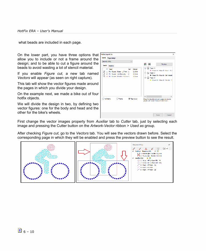
HotFix ERA – User's Manual
what beads are included in each page.
On the lower part, you have three options thatallow you to include or not a frame around thedesign; and to be able to cut a figure around thebeads to avoid wasting a lot of stencil material.
If you enable Figure cut, a new tab namedVectors will appear (as seen on right capture).
This tab will show the vector figures made aroundthe pages in which you divide your design.
On the example next, we made a bike out of fourhotfix objects.
We will divide the design in two, by defining twovector figures: one for the body and head and theother for the bike's wheels.
First change the vector images property from Auxiliar tab to Cutter tab, just by selecting eachimage and pressing the Cutter button on the Artwork-Vector ribbon > Used as group.
After checking Figure cut, go to the Vectors tab. You will see the vectors drawn before. Select thecorresponding page in which they will be enabled and press the preview button to see the result.
6 – 10

Hotfix Output
You will save a considerable amount of stencil material, by using this feature.
The Pen parameter is common for plotters andmilling machines.
Margin is a value used to enlarge the markexported for a given bead type, so the piececan be easily trapped by the stencil hole.
To organize pages, just drag the bead fromany page to any other: this action will producepages with several beads and pages with nobeads (with a red cross).
The system will generate a different file foreach page listed, but pages with the red cross(no beads) will be skipped.
When you press Save, the system displays a Save dialog where you indicate the path and filename for the PLT file. If multiple files are generates, the systems will automatically append anumber “-1”, “-2”, etc. to the file name.
Export to Windows Metafile and DXF formats
Windows Enhanced Metafile (EMF), is a vector based format well suited to be used with graphicsapplications like Adobe Ilustrator and CorelDRAW. The system exports the beads contours asclosed filled shapes using colors similar to the bead color. The Export to Metafile dialog box looksand behaves identical to the Beads tab of the Export to HPGL box.
DXF is a standard vector format commonly use as CAD interchange format. It is also used insome engravers, CNC and milling machines. The system exports the beads contours as straightsides polygons. The Export to DXF dialog box looks and behaves identical to the Beads tab of theExport to HPGL box.
6 - 11

HotFix ERA – User's Manual
Sending Hotfix to machines and devices
Through this command you can send hotix stone designs form the working window as atemplate/stencil to several machines and devices.
Access it from the File ribbon > Save > Export > Export As... > Send Hotfix Template/Stencil to...
or from the Hotfix ribbon > Export group > Send Hotfix
When you click on the option,a window will open.
You have three Send optionsto choose from: to Cutter; toHPGL; and to Engraver.
Click on the option you want.
Remember that Send Formats are optional plugins, so the list may be empty or contain justone or two items depending on what formats you have purchased.
TIP: If you plan to produce stencils (using a vinyl cutter orengraver) it may be useful to display, not only the piece contour,but the piece margin as well. Piece margin is used to cut orengrave a notch slightly larger than the piece itself to allow iteasier fit in. Use the check at Option and Preferences - Project -Hotfix - Show hotfix margin to enable or disable the margingdisplay. Use Hotfix margin size to set the value of the piecesmargin.
6 – 12

Hotfix Output
Sending information to CAMS machines
The command for sending a design to CAMS is accessedthrough the File ribbon > Save - Export group >Export/Send HotFix File or from the Hotfix ribbon > Exportgroup > Export Hotfix to machine
The dialog box named HOTFIX EXPORTER opens.
From Machine Brand select Yongnam Machines – CAMS;and from Model choose the one you want.
You can see two tabs: Position andBeads and Trays.
Position gives you informationabout your work area; lets you setyour margins, and also to changethe design orientation. You can alsoadd some repetitions.
The Bead and Trays tab lets youset the machine tray that should beused for each bead type and thedefault angle for the beads(required for CAMS 1V6P Option,that is able to set pieces in anyangle). Also a check in the firstcolumn lets you include or excludeany given bead from the output.
The Tray column lets you select thetray where the bead type is loadedin the machine (available formachines with several trays).
6 - 13
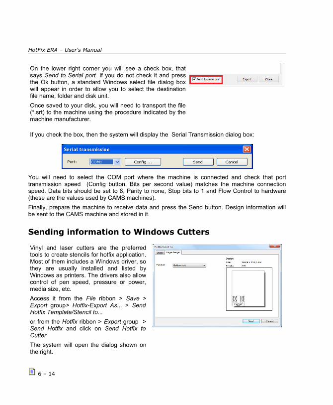
HotFix ERA – User's Manual
On the lower right corner you will see a check box, thatsays Send to Serial port. If you do not check it and pressthe Ok button, a standard Windows select file dialog boxwill appear in order to allow you to select the destinationfile name, folder and disk unit.
Once saved to your disk, you will need to transport the file(*.srt) to the machine using the procedure indicated by themachine manufacturer.
If you check the box, then the system will display the Serial Transmission dialog box:
You will need to select the COM port where the machine is connected and check that porttransmission speed (Config button, Bits per second value) matches the machine connectionspeed. Data bits should be set to 8, Parity to none, Stop bits to 1 and Flow Control to hardware(these are the values used by CAMS machines).
Finally, prepare the machine to receive data and press the Send button. Design information willbe sent to the CAMS machine and stored in it.
Sending information to Windows Cutters
Vinyl and laser cutters are the preferredtools to create stencils for hotfix application.Most of them includes a Windows driver, sothey are usually installed and listed byWindows as printers. The drivers also allowcontrol of pen speed, pressure or power,media size, etc.
Access it from the File ribbon > Save >Export group> Hotfix-Export As... > SendHotfix Template/Stencil to...
or from the Hotfix ribbon > Export group >Send Hotfix and click on Send Hotfix toCutter
The system will open the dialog shown onthe right.
6 – 14

Hotfix Output
You will save a considerable amount of stencil material, by using this feature.
It’s organized in two tabs:
Page design: This tab contains controlsto set the origin. Media size should be setfrom the driver.
Beads: This tab includes a bead list,where you define what bead types areincluded in the exported file, margin, and alist of Pages where you organize whatbeads are included in each page.
Margin is a value used to enlarge the markexported for a given bead type, so thepiece can be easily trapped by the stencilhole.
To organize pages, just drag the bead from any page to any other: this action will produce pageswith several beads and pages with no beads (with a red cross). The system will generate adifferent file for each page listed, but pages with the red cross (no beads) will be skipped.
On the lower part, you have three options that allow you to include or not a frame around thedesign; and to be able to cut a figure around the beads to avoid wasting a lot of stencil material.
If you enable Figure cut, a new tab named Vectors will appear (as seen on right capture).
This tab will show the vector figures made around the pages in which you divide your design.On the example next, we made a bike out of four hotfix objects. We will divide the design in two,by defining two vector figures: one for the body and head and the other for the bike's wheels.
First change the vector images property from auxiliar tab to cutter tab, just by selecting eachimage and pressing the Cutter button on the Artwork-Vector ribbon > Used as group.
After checking Figure cut, go to the Vectors tab. You will see the vectors drawn before. Select thecorresponding page in which they will be enabled.
6 - 15
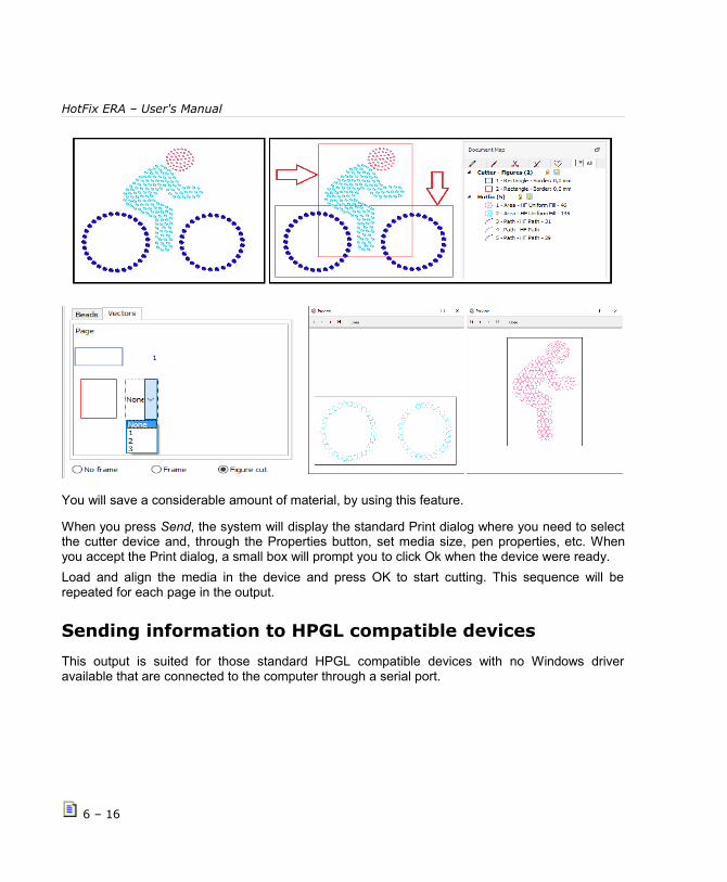
HotFix ERA – User's Manual
You will save a considerable amount of material, by using this feature.
When you press Send, the system will display the standard Print dialog where you need to selectthe cutter device and, through the Properties button, set media size, pen properties, etc. Whenyou accept the Print dialog, a small box will prompt you to click Ok when the device were ready.
Load and align the media in the device and press OK to start cutting. This sequence will berepeated for each page in the output.
Sending information to HPGL compatible devices
This output is suited for those standard HPGL compatible devices with no Windows driveravailable that are connected to the computer through a serial port.
6 – 16

Hotfix Output
Access it from the File ribbon > Save > Exportgroup> Hotfix-Export As... > Send HotfixTemplate/Stencil to...and click on Send Hotfixto HPGL Compatible Device
or from the Hotfix ribbon > Export group >Send Hotfix and click on Send Hotfix to HPGLCompatible Device.
The system will open the dialog shown at theright.
It’s organized in two tabs:
Page design: This tab contains controls to setthe media size and origin.
Beads: This tab includes a bead list, whereyou define what bead types are included inthe exported file and select the Pen number,and margin, and a list of Pages where youorganize what beads are included in eachpage.
Pen is a common parameter for plotters andmilling machines.
Margin is a value used to enlarge the markexported for a given bead type, so the piececan be easily trapped by the stencil hole.
On the lower part, you have three options that allow you to include or not a frame around thedesign; and to be able to cut a figure around the beads to avoid wasting a lot of stencil material.This part has been explained in previous pages.
To organize pages, just drag the bead from any page to any other: this action will produce pageswith several beads and pages with no beads (with a red cross). The system will generate adifferent file for each page listed, but pages with the red cross (no beads) will be skipped.
When you press Send, the system will display the SerialTransmission dialog box... select the COM port where thedevice is connected and check that port settings (Config...button) matches the device connection settings.
6 - 17

HotFix ERA – User's Manual
When you press Send, a small box will prompt you to clickOk when the device were ready.
Load and align the media in the device and press ok tostart data transmission.
This sequence will be repeated for each page in theoutput.
Sending information to Engravers
This output is suited for those engravers, CNC and milling machines that have a Windowscompatble driver (listed as standard printers). Using it, you may create the stencils required toproduce hotfix design using that method.
Access it from the File ribbon > Save > Exportgroup> Hotfix-Export As... > Send HotfixTemplate/Stencil to...and click on Send Hotfixto Engraver.
or from the Hotfix ribbon > Export group >Send Hotfix and click on Send Hotfix SendHotfix to Engraver.
The system will open the dialog shown on theright.
It’s organized in two tabs:
Page design: This tab contains controls to setthe media size and origin. You may alsoindicate to include alignment marks. In thiscase, you should define the tool number to beused to engrave the marks, the marksdiameter and the distance from the designboundaries to the marks.
6 – 18

Hotfix Output
Beads: This tab includes a bead list (top-left) atool list (bottom-left) and a pages list (right)
Using the Bead list you define which beadtypes will be send to the engraver, a marging(enlargement) to allow the bead to be easilytrapped into the hole made by de engraver andthe tool (as a color) that should be used toengrave the marks for each bead.
The Tool list lets you set the size of each toolused within the bead list.
The Pages list lets you control which beadtypes will be included within each engrave run(or “page”). You may include all the bead typeswithin one unique page or you may split the jobinto so many pages as different bead typesyour design uses.
6 - 19

HotFix ERA – User's Manual
Page intentionally left blank
6 – 20
Chapter 7
The SMART DESIGN tool
for Hotfix objectsCon ten t s :Smart Design.................................................................................................2
Smart Design in Objects Creation mode..................................................2
Smart Design in Object Editing mode.....................................................3
Smart Design in Vectors Digitizing mode.................................................5
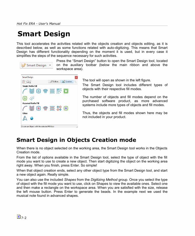
Hot Fix ERA - User's Manual
Smart DesignThis tool accelerates the activities related with the objects creation and objects editing, as it isdescribed below, as well as some functions related with auto-digitizing. This means that SmartDesign has different functionality depending on the moment it is used, but in every case itsimplifies the steps of the sequence necessary for such activities.
Press the “Smart Design” button to open the Smart Design tool, locatedon the auxiliary toolbar (below the main ribbon and above theworkspace area).
The tool will open as shown in the left figure.The Smart Design tool includes different types ofobjects with their respective fill modes.
The number of objects and fill modes depend on thepurchased software product, as more advancedsystems include more types of objects and fill modes.
Thus, the objects and fill modes shown here may benot included in your product.
Smart Design in Objects Creation modeWhen there is no object selected on the working area, the Smart Design tool works in the ObjectsCreation mode.
From the list of options available in the Smart Design tool, select the type of object with the fillmode you want to use to create a new object. Then start digitizing the object on the working arearight away. When you finish, press Enter. So simple!
When that object creation ends, select any other object type from the Smart Design tool, and starta new object again. Really simple.
You can also use the included Shapes from the Digitizing Method group. Once you select the typeof object with the fill mode you want to use, click on Shapes to view the available ones. Select oneand then make a rectangle on the workspace area. When you are satisfied with the size, releasethe left mouse button. Press Enter to generate the beads. In the example next we used themusical note found in advanced shapes.
7-2

The Smart Design tool
When you select the type of object in the Smart Design tool, the ribbon bar on the top of theworkspace toggles to the tab that includes the properties of the selected type of objects, whereyou can edit the characteristics of the object you are creating.
Note:
This function replaces and simplifies the sequence of steps to select the type of object and fillmode: HotFix Tab > Object Type > Fill Mode.
Smart Design in Object Editing modeWhen there is a selected object in the workspace, the Smart Design tools works in Object Editingmode. This means that if you click on one of the available modes, the Smart Design tool quicklyconverts the fill modes of the objects selected to the one you clicked on. You may also convertbetween some object types.
7-3
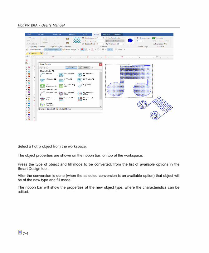
Hot Fix ERA - User's Manual
Select a hotfix object from the workspace.
The object properties are shown on the ribbon bar, on top of the workspace.
Press the type of object and fill mode to be converted, from the list of available options in theSmart Design tool.
After the conversion is done (when the selected conversion is an available option) that object willbe of the new type and fill mode.
The ribbon bar will show the properties of the new object type, where the characteristics can beedited.
7-4

The Smart Design tool
Note: Not all the type of objects can be converted to any kind of object types. In some cases the conversion cannot beperformed, and in some cases the conversion process may loose some of the objects characteristics (direction lines, andother elements).
Important: On the software products containing both decoration modes hotfix (rhinestone orsequin) and embroidery simultaneously, this tool may also convert rhinestone (or sequin)objects into embroidery objects and viceversa.
Smart Design in Vectors Digitizing modeWhen there is a vector shape in the workspace (from a vector graphic application), the SmartDesign tools works in Auto-Digitizing mode. In this case the Smart Design tool creates an object(embroidery or hotfix, according to the software features) with the shape of the selected vectors.This is the fastest way to create objects when the artwork comes from vector files.
The vector shapes may come from vector files made on other graphic applications, from art stockcollections, from vector shapes created on this application and also from the result ofvectorization of raster (bitmap) files.
7-5

Hot Fix ERA - User's Manual
Load the vector image ASV-010.emf from the Artwork ribbon > Vector group > Open Vector File. The image is on the following location:
C:\Users\Public\Pictures\Sierra Technology\Artwork Vector
As it may probably be a composition of many combined graphic elements,you need to Ungroup All the elements of the image (function on the ribbonbar while the image is selected).
After ungrouping, check the created geometric shapes (vectors).If required, use the combination tools (to simplify the shapes).
Once we have the final vectors, we may start auto-digitizing. Work on each vector, one at a time.
Click on the body of the peachto select it.
Now click on the Smart Tool,on the object type and fill modeyou want to use.
The Smart Design tool willcreate the new object, with theshape of the selected vector,using the fill mode you chose.
Next, we selected the peach contourvector, and chose HF Path to create thenew object (near right figure). Wechanged the color to black by clicking onthe black bead on the bead palette.Change Properties if needed from theribbon.
Repeat the procedure for the remainingvectors. See the final result on the figureon the far right.
7-6