version 1 - asrock.pc.cdn.bitgravity.comasrock.pc.cdn.bitgravity.com/manual/h310cm-itxac.pdf ·...
TRANSCRIPT

Version 1.0 Published October 2018 Copyright©2018 ASRock INC. All rights reserved.
Copyright Notice:No part of this documentation may be reproduced, transcribed, transmitted, or translated in any language, in any form or by any means, except duplication of documentation by the purchaser for backup purpose, without written consent of ASRock Inc.
Products and corporate names appearing in this documentation may or may not be registered trademarks or copyrights of their respective companies, and are used only for identification or explanation and to the owners’ benefit, without intent to infringe.
Disclaimer:Specifications and information contained in this documentation are furnished for informational use only and subject to change without notice, and should not be constructed as a commitment by ASRock. ASRock assumes no responsibility for any errors or omissions that may appear in this documentation.
With respect to the contents of this documentation, ASRock does not provide warranty of any kind, either expressed or implied, including but not limited to the implied warranties or conditions of merchantability or fitness for a particular purpose.
In no event shall ASRock, its directors, officers, employees, or agents be liable for any indirect, special, incidental, or consequential damages (including damages for loss of profits, loss of business, loss of data, interruption of business and the like), even if ASRock has been advised of the possibility of such damages arising from any defect or error in the documentation or product.
This device complies with Part 15 of the FCC Rules. Operation is subject to the following two conditions: (1) this device may not cause harmful interference, and (2) this device must accept any interference received, including interference that
may cause undesired operation.
CALIFORNIA, USA ONLYThe Lithium battery adopted on this motherboard contains Perchlorate, a toxic substance controlled in Perchlorate Best Management Practices (BMP) regulations passed by the California Legislature. When you discard the Lithium battery in California, USA, please follow the related regulations in advance.“Perchlorate Material-special handling may apply, see www.dtsc.ca.gov/hazardouswaste/perchlorate”
ASRock Website: http://www.asrock.com

AUSTRALIA ONLYOur goods come with guarantees that cannot be excluded under the Australian Consumer Law. You are entitled to a replacement or refund for a major failure and compensation for any other reasonably foreseeable loss or damage caused by our goods. You are also entitled to have the goods repaired or replaced if the goods fail to be of acceptable quality and the failure does not amount to a major failure. If you require assistance please call ASRock Tel : +886-2-28965588 ext.123 (Standard International call charges apply)
The terms HDMI® and HDMI High-Definition Multimedia Interface, and the HDMI logo are trademarks or registered trademarks of HDMI Licensing LLC in the United States and other countries.
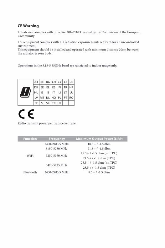
CE WarningThis device complies with directive 2014/53/EU issued by the Commision of the European Community.
This equipment complies with EU radiation exposure limits set forth for an uncontrolled environment. This equipment should be installed and operated with minimum distance 20cm between the radiator & your body.
Operations in the 5.15-5.35GHz band are restricted to indoor usage only.
Radio transmit power per transceiver type
Function Frequency Maximum Output Power (EIRP)
WiFi
2400-2483.5 MHz 18.5 + / -1.5 dbm5150-5250 MHz 21.5 + / -1.5 dbm
5250-5350 MHz18.5 + / -1.5 dbm (no TPC)
21.5 + / -1.5 dbm (TPC)
5470-5725 MHz25.5 + / -1.5 dbm (no TPC)
28.5 + / -1.5 dbm (TPC)Bluetooth 2400-2483.5 MHz 8.5 + / -1.5 dbm
Contents
Chapter 1 Introduction 1
1.1 Package Contents 1
1.2 Specifications 2
1.3 Motherboard Layout 6
1.4 I/O Panel 8
1.5 WiFi-802.11ac Module and ASRock WiFi 2.4/5 GHz Antenna 10
Chapter 2 Installation 12
2.1 Installing the CPU 13
2.2 Installing the CPU Fan and Heatsink 16
2.3 Installing Memory Modules (DIMM) 17
2.4 Expansion Slot (PCI Express Slot) 19
2.5 Jumpers Setup 20
2.6 Onboard Headers and Connectors 21
2.7 M.2_SSD (NGFF) Module Installation Guide (M2_1) 25
Chapter 3 Software and Utilities Operation 27
3.1 Installing Drivers 27
3.2 A-Tuning 28
3.2.1 Installing A-Tuning 28
3.2.2 Using A-Tuning 28
3.3 ASRock Live Update & APP Shop 31
3.3.1 UI Overview 31
3.3.2 Apps 32
3.3.3 BIOS & Drivers 35
3.3.4 Setting 36
Chapter 4 UEFI SETUP UTILITY 37
4.1 Introduction 37
4.2 EZ Mode 38
4.3 Advanced Mode 39
4.3.1 UEFI Menu Bar 39
4.3.2 Navigation Keys 40
4.4 Main Screen 41
4.5 OC Tweaker Screen 42
4.6 Advanced Screen 51
4.6.1 CPU Configuration 52
4.6.2 Chipset Configuration 54
4.6.3 Storage Configuration 56
4.6.4 Super IO Configuration 57
4.6.5 ACPI Configuration 58
4.6.6 USB Configuration 59
4.6.7 Trusted Computing 60
4.7 Tools 61
4.8 Hardware Health Event Monitoring Screen 63
4.9 Security Screen 65
4.10 Boot Screen 66
4.11 Exit Screen 69
PB 1
Engl
ish
H310CM-ITX/ac
Chapter 1 IntroductionThank you for purchasing ASRock H310CM-ITX/ac motherboard, a reliable motherboard produced under ASRock’s consistently stringent quality control. It delivers excellent performance with robust design conforming to ASRock’s commitment to quality and endurance.
In this documentation, Chapter 1 and 2 contains the introduction of the motherboard and step-by-step installation guides. Chapter 3 contains the operation guide of the software and utilities. Chapter 4 contains the configuration guide of the BIOS setup.
1.1 Package Contents• ASRock H310CM-ITX/ac Motherboard (Mini-ITX Form Factor)• ASRock H310CM-ITX/ac Quick Installation Guide • ASRock H310CM-ITX/ac Support CD • 2 x Serial ATA (SATA) Data Cables (Optional)• 1 x I/O Panel Shield • 2 x ASRock WiFi 2.4/5 GHz Antennas (Optional)• 1 x Screw for M.2 Socket (Optional)
Because the motherboard specifications and the BIOS software might be updated, the content of this documentation will be subject to change without notice. In case any modi-fications of this documentation occur, the updated version will be available on ASRock’s website without further notice. If you require technical support related to this mother-board, please visit our website for specific information about the model you are using. You may find the latest VGA cards and CPU support list on ASRock’s website as well. ASRock website http://www.asrock.com.
2 3
English
1.2 Specifications
Platform • Mini-ITX Form Factor• Solid Capacitor design
CPU • Supports 8th Generation Intel® CoreTM Processors (Socket 1151)
• Digi Power design• 5 Power Phase design• Supports Intel® Turbo Boost 2.0 Technology
Chipset • Intel® H310
Memory • Dual Channel DDR4 Memory Technology• 2 x DDR4 DIMM Slots• Supports DDR4 2666/2400/2133 non-ECC, un-buffered
memory• Supports ECC UDIMM memory modules (operate in non-
ECC mode)• Max. capacity of system memory: 32GB• Supports Intel® Extreme Memory Profile (XMP) 2.0• 15μ Gold Contact in DIMM Slots
Expansion Slot
• 1 x PCI Express 3.0 x16 Slot (PCIE1: x16 mode)* Supports NVMe SSD as boot disks• 1 x Vertical M.2 Socket (Key E) with the bundled WiFi-
802.11ac module (on the rear I/O)
Graphics * Intel® UHD Graphics Built-in Visuals and the VGA outputs can be supported only with processors which are GPU integrated. • Supports Intel® UHD Graphics Built-in Visuals : Intel®
Quick Sync Video with AVC, MVC (S3D) and MPEG-2 Full HW Encode1, Intel® InTruTM 3D, Intel® Clear Video HD Technology, Intel® InsiderTM, Intel® UHD Graphics
• DirectX 12
2 3
Engl
ish
H310CM-ITX/ac
• HWAEncode/Decode: AVC/H.264, HEVC/H.265 8-bit, HEVC/H.265 10-bit, VP8, VP9 8-bit, VP9 10-bit (Decode only), MPEG2, MJPEG, VC-1 (Decode only)
• Three graphics output options: DVI-I, HDMI and DisplayPort 1.2
* Supports up to 2 displays simultaneously• Supports HDMI with max. resolution up to 4K x 2K
(4096x2160) @ 30Hz• Supports DisplayPort 1.2 with max. resolution up to 4K x 2K
(4096x2304) @ 60Hz• Supports DVI-I with max. resolution up to 1920x1200 @
60Hz• Supports Auto Lip Sync, Deep Color (12bpc), xvYCC and
HBR (High Bit Rate Audio) with HDMI Port (Compliant HDMI monitor is required)
• Supports HDCP with DVI-I, HDMI and DisplayPort 1.2 Ports
• Supports 4K Ultra HD (UHD) playback with HDMI and DisplayPort 1.2 Ports
Audio • 7.1 CH HD Audio (Realtek ALC887 Audio Codec) * To configure 7.1 CH HD Audio, it is required to use an HD front panel audio module and enable the multi-channel audio feature through the audio driver.• Supports Surge Protection• ELNA Audio Caps
LAN • Gigabit LAN 10/100/1000 Mb/s• Giga PHY Intel® I219V• Supports Wake-On-LAN • Supports Lightning/ESD Protection• Supports Energy Efficient Ethernet 802.3az• Supports PXE
4 5
English
Wireless LAN
• Intel® 802.11ac WiFi Module • Supports IEEE 802.11a/b/g/n/ac• Supports Dual-Band (2.4/5 GHz)• Supports high speed wireless connections up to 433Mbps• Supports Bluetooth 4.2 / 3.0 + High speed class II
Rear Panel I/O
• 2 x Antenna Ports• 1 x PS/2 Mouse/Keyboard Port • 1 x DVI-I Port• 1 x HDMI Port• 1 x DisplayPort 1.2• 2 x USB 2.0 Ports (Supports ESD Protection)• 2 x USB 3.1 Gen1 Ports (Supports ESD Protection)• 1 x RJ-45 LAN Port with LED (ACT/LINK LED and SPEED
LED)• HD Audio Jacks: Line in / Front Speaker / Microphone
Storage • 4 x SATA3 6.0 Gb/s Connectors, support NCQ, AHCI and Hot Plug*
* If M2_1 is occupied by a SATA-type M.2 device, SATA3_0 will be disabled.• 1 x M.2 Socket, supports M Key type 2280 M.2 SATA3 6.0
Gb/s module and M.2 PCI Express module up to Gen2 x4 (20 Gb/s)**
** Supports NVMe SSD as boot disks** Supports ASRock U.2 Kit
Connector • 1 x Chassis Intrusion Headers• 1 x CPU Fan Connector (4-pin)
* The CPU Fan Connector supports the CPU fan of maximum 1A (12W) fan power. • 1 x Chassis Fan Connector (4-pin)
* The Chassis Fan Connector supports the Chassis fan of maxi-mum 1A (12W) fan power. • 1 x Chassis/Water Pump Fan Connector (4-pin) (Smart Fan
Speed Control)* The Chassis/Water Pump Fan supports the water cooler fan of maximum 2A (24W) fan power.* CHA_FAN1/WP can auto detect if 3-pin or 4-pin fan is in use.
4 5
Engl
ish
H310CM-ITX/ac
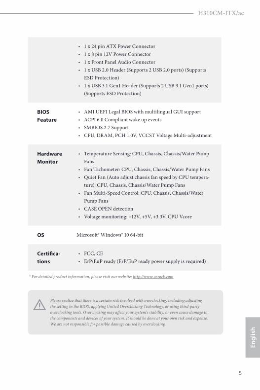
• 1 x 24 pin ATX Power Connector • 1 x 8 pin 12V Power Connector • 1 x Front Panel Audio Connector • 1 x USB 2.0 Header (Supports 2 USB 2.0 ports) (Supports
ESD Protection)• 1 x USB 3.1 Gen1 Header (Supports 2 USB 3.1 Gen1 ports)
(Supports ESD Protection)
BIOS Feature
• AMI UEFI Legal BIOS with multilingual GUI support • ACPI 6.0 Compliant wake up events• SMBIOS 2.7 Support• CPU, DRAM, PCH 1.0V, VCCST Voltage Multi-adjustment
Hardware Monitor
• Temperature Sensing: CPU, Chassis, Chassis/Water Pump Fans
• Fan Tachometer: CPU, Chassis, Chassis/Water Pump Fans • Quiet Fan (Auto adjust chassis fan speed by CPU tempera-
ture): CPU, Chassis, Chassis/Water Pump Fans • Fan Multi-Speed Control: CPU, Chassis, Chassis/Water
Pump Fans • CASE OPEN detection• Voltage monitoring: +12V, +5V, +3.3V, CPU Vcore
OS Microsoft® Windows® 10 64-bit
Certifica-tions
• FCC, CE• ErP/EuP ready (ErP/EuP ready power supply is required)
Please realize that there is a certain risk involved with overclocking, including adjusting the setting in the BIOS, applying Untied Overclocking Technology, or using third-party overclocking tools. Overclocking may affect your system’s stability, or even cause damage to the components and devices of your system. It should be done at your own risk and expense. We are not responsible for possible damage caused by overclocking.
* For detailed product information, please visit our website: http://www.asrock.com
6 7
English
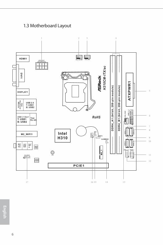
PCIE1
DD
R4
_A
1 (
64
bit
, 2
88
-pin
mo
du
le)
DD
R4
_B
1 (
64
bit
, 2
88
-pin
mo
du
le)
CPU_FAN1CHA_FAN1/WP
RoHS
H3
10
CM
-IT
X/a
c
3
6
8
7
PS
2K
ey
bo
ard
/Mo
us
e
16 15 14
AUDIOCODEC
5
1
HD_AUDIO1
1
SP
EA
KE
R1Intel
H310
AT
XP
WR
1U
SB
3_
3_
4
1
42
PANEL1
HD
LE
D R
ES
ET
PL
ED
P
WR
BT
N
1
Top:LIN
E IN
Center:
FRO
NT
Bottom
:M
IC IN
SA
TA
3_
3
SA
TA
3_
2
1
CLRMOS1
SA
TA
3_
1
SA
TA
3_
0
1
USB_3_4
M2
_1
C 1T
Top:RJ-45
USB 3.1 Gen1
T: USB1B: USB2
USB 2.0T: USB1B: USB2
1
9
10
11
12
BIOSROM
M2_WIFI1
DISPLAY1
17
HDMI1
DV
I1
CI1
1BAT1
CH
A_
FA
N2
13
1.3 Motherboard Layout
6 7
Engl
ish
H310CM-ITX/ac
No. Description
1 ATX 12V Power Connector (ATX12V1)
2 Chassis Fan / Waterpump Fan Connector (CHA_FAN1/WP)
3 CPU Fan Connector (CPU_FAN1)
4 2 x 288-pin DDR4 DIMM Slots (DDR4_A1, DDR4_B1)
5 ATX Power Connector (ATXPWR1)
6 USB 3.1 Gen1 Header (USB3_3_4)
7 SATA3 Connector (SATA3_1)
8 SATA3 Connector (SATA3_0)
9 SATA3 Connector (SATA3_3)
10 SATA3 Connector (SATA3_2)
11 System Panel Header (PANEL1)
12 USB 2.0 Header (USB_3_4)
13 Chassis Fan Connector (CHA_FAN2)
14 Clear CMOS Jumper (CLRMOS1)
15 Chassis Intrusion Header (CI1)
16 Chassis Speaker Header (SPEAKER1)
17 Front Panel Audio Header (HD_AUDIO1)
8 9
English
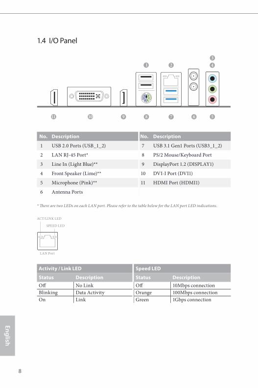
1.4 I/O Panel
No. Description No. Description
1 USB 2.0 Ports (USB_1_2) 7 USB 3.1 Gen1 Ports (USB3_1_2)
2 LAN RJ-45 Port* 8 PS/2 Mouse/Keyboard Port
3 Line In (Light Blue)** 9 DisplayPort 1.2 (DISPLAY1)
4 Front Speaker (Lime)** 10 DVI-I Port (DVI1)
5 Microphone (Pink)** 11 HDMI Port (HDMI1)
6 Antenna Ports
* There are two LEDs on each LAN port. Please refer to the table below for the LAN port LED indications.
Activity / Link LED Speed LED
Status Description Status DescriptionOff No Link Off 10Mbps connectionBlinking Data Activity Orange 100Mbps connectionOn Link Green 1Gbps connection
ACT/LINK LED
SPEED LED
LAN Port
11 57810
21
9
43
6
8 9
Engl
ish
H310CM-ITX/ac
** To configure 7.1 CH HD Audio, it is required to use an HD front panel audio module and enable the multi-channel audio feature through the audio driver.
Please set Speaker Configuration to “7.1 Speaker”in the Realtek HD Audio Manager.
Function of the Audio Ports in 7.1-channel Configuration:
Port FunctionLight Blue (Rear panel) Rear Speaker OutLime (Rear panel) Front Speaker OutPink (Rear panel) Central /Subwoofer Speaker OutLime (Front panel) Side Speaker Out

10 11
English
1.5 WiFi-802.11ac Module and ASRock WiFi 2.4/5 GHz Antenna
WiFi-802.11ac + BT ModuleThis motherboard comes with an exclusive WiFi 802.11 a/b/g/n/ac + BT v4.2 module (pre-installed on the rear I/O panel) that offers support for WiFi 802.11 a/b/g/n/ac connectivity standards and Bluetooth v4.2. WiFi + BT module is an easy-to-use wireless local area network (WLAN) adapter to support WiFi + BT. Bluetooth v4.2 standard features Smart Ready technology that adds a whole new class of functionality into the mobile devices. BT 4.2 also includes Low Energy Technology and ensures extraordinary low power consumption for PCs. * The transmission speed may vary according to the environment.
10 11
Engl
ish
H310CM-ITX/ac
WiFi Antennas Installation Guide
Step 1
Prepare the WiFi 2.4/5 GHz Antennas that come with the package.
Step 2
Connect the two WiFi 2.4/5 GHz Antennas to the antenna connectors. Turn the antenna clock-wise until it is securely connected.
Step 3
Set the WiFi 2.4/5 GHz Antenna as shown in the illustration.
*You may need to adjust the direction of the antenna for a stronger signal.
12 13
English
This is a Mini-ITX form factor motherboard. Before you install the motherboard, study the configuration of your chassis to ensure that the motherboard fits into it.
Pre-installation PrecautionsTake note of the following precautions before you install motherboard components or change any motherboard settings.
• Make sure to unplug the power cord before installing or removing the motherboard components. Failure to do so may cause physical injuries and damages to motherboard components.
• In order to avoid damage from static electricity to the motherboard’s components, NEVER place your motherboard directly on a carpet. Also remember to use a grounded wrist strap or touch a safety grounded object before you handle the components.
• Hold components by the edges and do not touch the ICs.• Whenever you uninstall any components, place them on a grounded anti-static pad or
in the bag that comes with the components.• When placing screws to secure the motherboard to the chassis, please do not over-
tighten the screws! Doing so may damage the motherboard.
Chapter 2 Installation
12 13
Engl
ish
H310CM-ITX/ac
2.1 Installing the CPU
1. Before you insert the 1151-Pin CPU into the socket, please check if the PnP cap is on the socket, if the CPU surface is unclean, or if there are any bent pins in the socket. Do not force to insert the CPU into the socket if above situation is found. Otherwise, the CPU will be seriously damaged.
2. Unplug all power cables before installing the CPU.
1
2
A
B
14 15
English
4
5
3

14 15
Engl
ish
H310CM-ITX/ac
Please save and replace the cover if the processor is removed. The cover must be placed if you wish to return the motherboard for after service.
16 17
English
2.2 Installing the CPU Fan and Heatsink
1 2
CPU_FAN
16 17
Engl
ish
H310CM-ITX/ac
2.3 Installing Memory Modules (DIMM)
This motherboard provides two 288-pin DDR4 (Double Data Rate 4) DIMM slots, and supports Dual Channel Memory Technology.
The DIMM only fits in one correct orientation. It will cause permanent damage to the motherboard and the DIMM if you force the DIMM into the slot at incorrect orientation.
1. For dual channel configuration, you always need to install identical (the same brand, speed, size and chip-type) DDR4 DIMM pairs.
2. It is unable to activate Dual Channel Memory Technology with only one memory module installed.
3. It is not allowed to install a DDR, DDR2 or DDR3 memory module into a DDR4 slot; otherwise, this motherboard and DIMM may be damaged..
18 19
English
1
2
3
18 19
Engl
ish
H310CM-ITX/ac
2.4 Expansion Slot (PCI Express Slot)There is 1 PCI Express slot on the motherboard.
PCIe slot:
PCIE1 (PCIe 3.0 x16 slot) is used for PCI Express x16 lane width graphics cards.
Before installing an expansion card, please make sure that the power supply is switched off or the power cord is unplugged. Please read the documentation of the expansion card and make necessary hardware settings for the card before you start the installation.
20 21
English
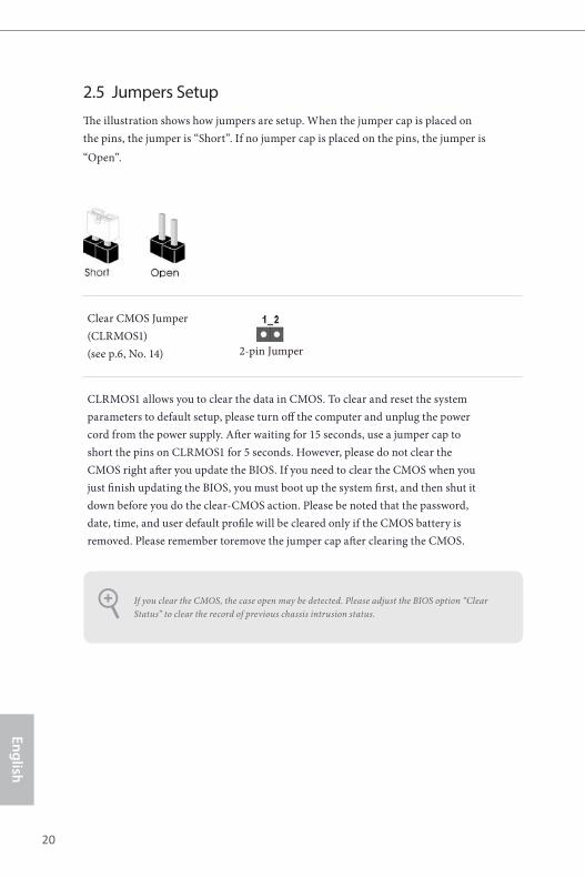
2.5 Jumpers SetupThe illustration shows how jumpers are setup. When the jumper cap is placed on the pins, the jumper is “Short”. If no jumper cap is placed on the pins, the jumper is “Open”.
Clear CMOS Jumper(CLRMOS1)(see p.6, No. 14)
CLRMOS1 allows you to clear the data in CMOS. To clear and reset the system parameters to default setup, please turn off the computer and unplug the power cord from the power supply. After waiting for 15 seconds, use a jumper cap to short the pins on CLRMOS1 for 5 seconds. However, please do not clear the CMOS right after you update the BIOS. If you need to clear the CMOS when you just finish updating the BIOS, you must boot up the system first, and then shut it down before you do the clear-CMOS action. Please be noted that the password, date, time, and user default profile will be cleared only if the CMOS battery is removed. Please remember toremove the jumper cap after clearing the CMOS.
If you clear the CMOS, the case open may be detected. Please adjust the BIOS option “Clear Status” to clear the record of previous chassis intrusion status.
2-pin Jumper
20 21
Engl
ish
H310CM-ITX/ac
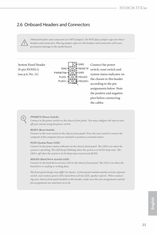
2.6 Onboard Headers and Connectors
System Panel Header(9-pin PANEL1)(see p.6, No. 11)
GND RESET#
PWRBTN#
PLED-
PLED+
GND
HDLED-
HDLED+
1
GND Connect the power switch, reset switch and system status indicator on the chassis to this header according to the pin assignments below. Note the positive and negative pins before connecting the cables.
PWRBTN (Power Switch): Connect to the power switch on the chassis front panel. You may configure the way to turn off your system using the power switch.
RESET (Reset Switch): Connect to the reset switch on the chassis front panel. Press the reset switch to restart the computer if the computer freezes and fails to perform a normal restart.
PLED (System Power LED): Connect to the power status indicator on the chassis front panel. The LED is on when the system is operating. The LED keeps blinking when the system is in S1/S3 sleep state. The LED is off when the system is in S4 sleep state or powered off (S5).
HDLED (Hard Drive Activity LED): Connect to the hard drive activity LED on the chassis front panel. The LED is on when the hard drive is reading or writing data.
The front panel design may differ by chassis. A front panel module mainly consists of power switch, reset switch, power LED, hard drive activity LED, speaker and etc. When connect-ing your chassis front panel module to this header, make sure the wire assignments and the pin assignments are matched correctly.
Onboard headers and connectors are NOT jumpers. Do NOT place jumper caps over these headers and connectors. Placing jumper caps over the headers and connectors will cause permanent damage to the motherboard.
22 23
English
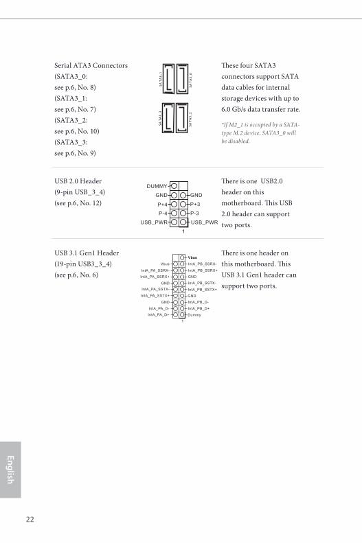
Serial ATA3 Connectors(SATA3_0: see p.6, No. 8) (SATA3_1: see p.6, No. 7) (SATA3_2: see p.6, No. 10) (SATA3_3: see p.6, No. 9)
These four SATA3 connectors support SATA data cables for internal storage devices with up to 6.0 Gb/s data transfer rate.
*If M2_1 is occupied by a SATA-type M.2 device, SATA3_0 will be disabled.
USB 2.0 Header (9-pin USB_3_4)(see p.6, No. 12)
DUMMY
GND GND
P+4
P-4
P+3
P-3
USB_PWR USB_PWR
1
There is one USB2.0 header on this motherboard. This USB 2.0 header can support two ports.
USB 3.1 Gen1 Header(19-pin USB3_3_4)(see p.6, No. 6)
1
IntA_PB_D+
Dummy
IntA_PB_D-
GND
IntA_PB_SSTX+
GND
IntA_PB_SSTX-
IntA_PB_SSRX+
IntA_PB_SSRX-
VbusVbus
Vbus
IntA_PA_SSRX-
IntA_PA_SSRX+
GND
IntA_PA_SSTX-
IntA_PA_SSTX+
GND
IntA_PA_D-
IntA_PA_D+
There is one header on this motherboard. This USB 3.1 Gen1 header can support two ports.
SATA
3_3
SATA
3_2
SATA
3_1
SATA
3_0
22 23
Engl
ish
H310CM-ITX/ac
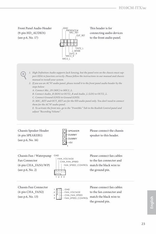
Front Panel Audio Header(9-pin HD_AUDIO1)(see p.6, No. 17)
J_SENSE
OUT2_L
1
MIC_RETPRESENCE#
GND
OUT2_RMIC2_R
MIC2_L
OUT_RET
This header is for connecting audio devices to the front audio panel.
Chassis Speaker Header(4-pin SPEAKER1)(see p.6, No. 16) DUMMY
SPEAKER
1
DUMMY
+5V
Please connect the chassis speaker to this header.
Chassis Fan / Waterpump Fan Connector(4-pin CHA_FAN1/WP)(see p.6, No. 2)
GNDFAN_VOLTAGECHA_FAN_SPEED
FAN_SPEED_CONTROL
1 2 3 4
Please connect fan cables to the fan connector and match the black wire to the ground pin.
Chassis Fan Connector(4-pin CHA_FAN2)(see p.6, No. 13)
GNDFAN_VOLTAGECHA_FAN_SPEEDFAN_SPEED_CONTROL
1234
Please connect fan cables to the fan connector and match the black wire to the ground pin.
1. High Definition Audio supports Jack Sensing, but the panel wire on the chassis must sup-port HDA to function correctly. Please follow the instructions in our manual and chassis manual to install your system.
2. If you use an AC’97 audio panel, please install it to the front panel audio header by the steps below: A. Connect Mic_IN (MIC) to MIC2_L. B. Connect Audio_R (RIN) to OUT2_R and Audio_L (LIN) to OUT2_L. C. Connect Ground (GND) to Ground (GND). D. MIC_RET and OUT_RET are for the HD audio panel only. You don’t need to connect them for the AC’97 audio panel. E. To activate the front mic, go to the “FrontMic” Tab in the Realtek Control panel and adjust “Recording Volume”.
24 25
English
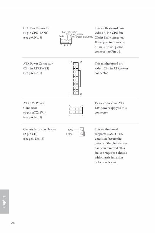
CPU Fan Connector(4-pin CPU_FAN1)(see p.6, No. 3) GND
FAN_VOLTAGECPU_FAN_SPEED
FAN_SPEED_CONTROL
1 2 3 4
This motherboard pro-vides a 4-Pin CPU fan (Quiet Fan) connector. If you plan to connect a 3-Pin CPU fan, please connect it to Pin 1-3.
ATX Power Connector(24-pin ATXPWR1)(see p.6, No. 5)
12
1
24
13
This motherboard pro-vides a 24-pin ATX power connector.
ATX 12V Power Connector(4-pin ATX12V1)(see p.6, No. 1)
5
1
8
4
Please connect an ATX 12V power supply to this connector.
Chassis Intrusion Header(2-pin CI1) (see p.6, No. 15)
1Signal
GND This motherboard supports CASE OPEN detection feature that detects if the chassis cove has been removed. This feature requires a chassis with chassis intrusion detection design.
24 25
Engl
ish
H310CM-ITX/ac
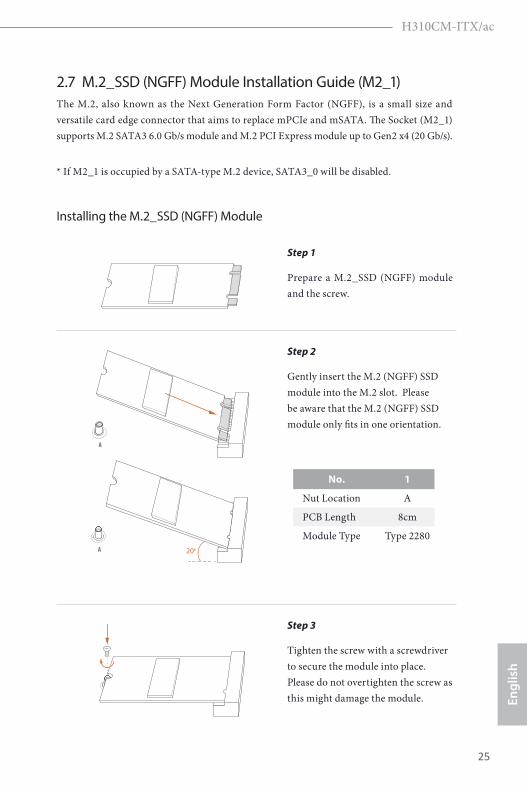
2.7 M.2_SSD (NGFF) Module Installation Guide (M2_1)The M.2, also known as the Next Generation Form Factor (NGFF), is a small size and versatile card edge connector that aims to replace mPCIe and mSATA. The Socket (M2_1) supports M.2 SATA3 6.0 Gb/s module and M.2 PCI Express module up to Gen2 x4 (20 Gb/s).
* If M2_1 is occupied by a SATA-type M.2 device, SATA3_0 will be disabled.
Installing the M.2_SSD (NGFF) Module
Step 1
Prepare a M.2_SSD (NGFF) module and the screw.
A
A 20o
Step 2
Gently insert the M.2 (NGFF) SSD module into the M.2 slot. Please be aware that the M.2 (NGFF) SSD module only fits in one orientation.
NUT1NUT2
Step 3
Tighten the screw with a screwdriver to secure the module into place. Please do not overtighten the screw as this might damage the module.
No. 1
Nut Location A
PCB Length 8cm
Module Type Type 2280
26 27
English
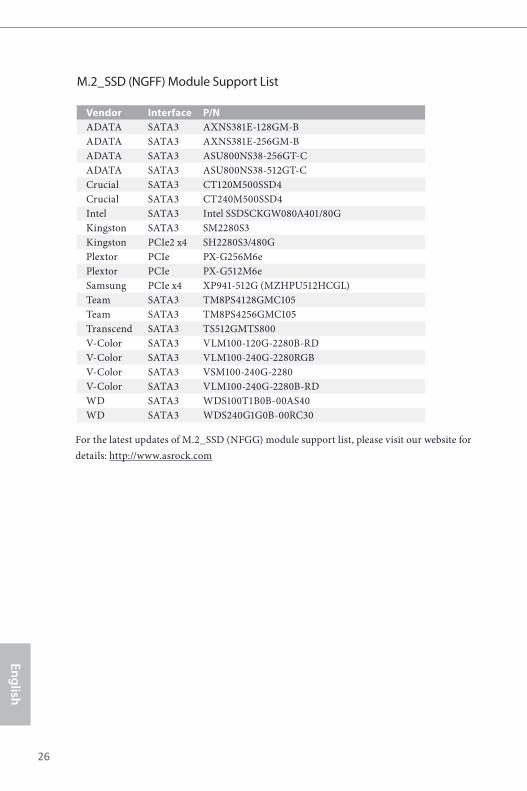
M.2_SSD (NGFF) Module Support List
Vendor Interface P/NADATA SATA3 AXNS381E-128GM-BADATA SATA3 AXNS381E-256GM-BADATA SATA3 ASU800NS38-256GT-CADATA SATA3 ASU800NS38-512GT-CCrucial SATA3 CT120M500SSD4Crucial SATA3 CT240M500SSD4Intel SATA3 Intel SSDSCKGW080A401/80GKingston SATA3 SM2280S3Kingston PCIe2 x4 SH2280S3/480GPlextor PCIe PX-G256M6ePlextor PCIe PX-G512M6eSamsung PCIe x4 XP941-512G (MZHPU512HCGL)Team SATA3 TM8PS4128GMC105Team SATA3 TM8PS4256GMC105Transcend SATA3 TS512GMTS800V-Color SATA3 VLM100-120G-2280B-RDV-Color SATA3 VLM100-240G-2280RGBV-Color SATA3 VSM100-240G-2280V-Color SATA3 VLM100-240G-2280B-RDWD SATA3 WDS100T1B0B-00AS40WD SATA3 WDS240G1G0B-00RC30
For the latest updates of M.2_SSD (NFGG) module support list, please visit our website for details: http://www.asrock.com
26 27
Engl
ish
H310CM-ITX/ac
Chapter 3 Software and Utilities Operation 3.1 Installing DriversThe Support CD that comes with the motherboard contains necessary drivers and useful utilities that enhance the motherboard’s features.
Running The Support CDTo begin using the support CD, insert the CD into your CD-ROM drive. The CD automatically displays the Main Menu if “AUTORUN” is enabled in your computer. If the Main Menu does not appear automatically, locate and double click on the file “ASRSETUP.EXE” in the Support CD to display the menu.
Drivers MenuThe drivers compatible to your system will be auto-detected and listed on the support CD driver page. Please click Install All or follow the order from top to bottom to install those required drivers. Therefore, the drivers you install can work properly.
Utilities MenuThe Utilities Menu shows the application software that the motherboard supports. Click on a specific item then follow the installation wizard to install it.
28 29
English
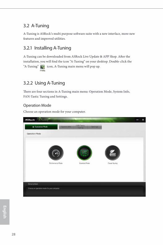
3.2 A-TuningA-Tuning is ASRock’s multi purpose software suite with a new interface, more new features and improved utilities.
3.2.1 Installing A-Tuning
A-Tuning can be downloaded from ASRock Live Update & APP Shop. After the installation, you will find the icon “A-Tuning“ on your desktop. Double-click the “A-Tuning“ icon, A-Tuning main menu will pop up.
3.2.2 Using A-Tuning
There are four sections in A-Tuning main menu: Operation Mode, System Info, FAN-Tastic Tuning and Settings.
Operation ModeChoose an operation mode for your computer.
28 29
Engl
ish
H310CM-ITX/ac
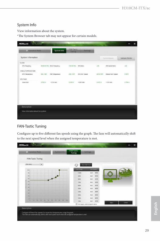
System InfoView information about the system. *The System Browser tab may not appear for certain models.
FAN-Tastic Tuning
Configure up to five different fan speeds using the graph. The fans will automatically shift to the next speed level when the assigned temperature is met.
30 31
English
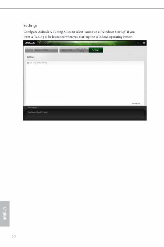
SettingsConfigure ASRock A-Tuning. Click to select "Auto run at Windows Startup" if you want A-Tuning to be launched when you start up the Windows operating system.
30 31
Engl
ish
H310CM-ITX/ac
3.3 ASRock Live Update & APP ShopThe ASRock Live Update & APP Shop is an online store for purchasing and downloading software applications for your ASRock computer. You can quickly and easily install various apps and support utilities. With ASRock Live Update & APP Shop, you can optimize your system and keep your motherboard up to date simply with a few clicks.
Double-click on your desktop to access ASRock Live Update & APP Shop utility.
*You need to be connected to the Internet to download apps from the ASRock Live Update & APP Shop.
3.3.1 UI Overview
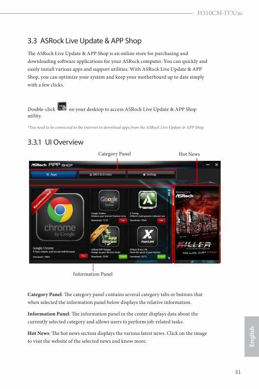
Category Panel: The category panel contains several category tabs or buttons that when selected the information panel below displays the relative information.
Information Panel: The information panel in the center displays data about the currently selected category and allows users to perform job-related tasks.
Hot News: The hot news section displays the various latest news. Click on the image to visit the website of the selected news and know more.
Information Panel
Hot NewsCategory Panel
32 33
English
3.3.2 Apps
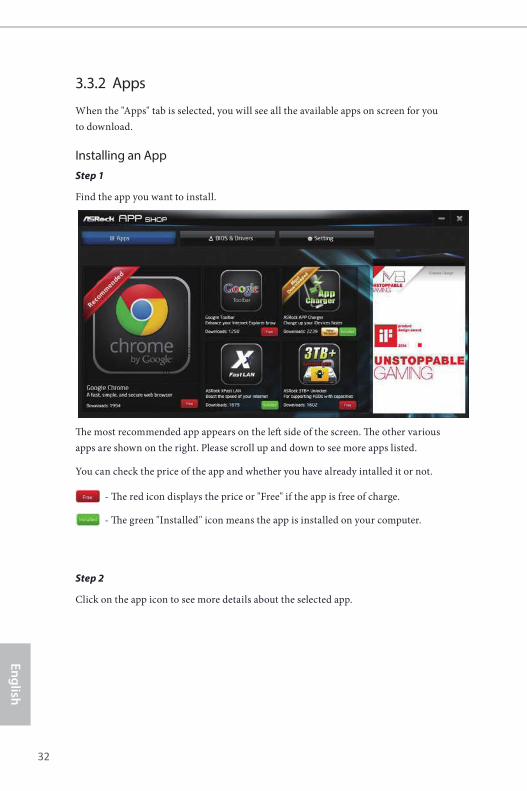
When the "Apps" tab is selected, you will see all the available apps on screen for you to download.
Installing an AppStep 1
Find the app you want to install.
Th e most recommended app appears on the left side of the screen. Th e other various apps are shown on the right. Please scroll up and down to see more apps listed.
You can check the price of the app and whether you have already intalled it or not.
- Th e red icon displays the price or "Free" if the app is free of charge.
- Th e green "Installed" icon means the app is installed on your computer.
Step 2
Click on the app icon to see more details about the selected app.
32 33
Engl
ish
H310CM-ITX/ac
Step 3
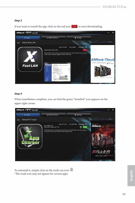
If you want to install the app, click on the red icon to start downloading.
Step 4
When installation completes, you can fi nd the green "Installed" icon appears on the upper right corner.
To uninstall it, simply click on the trash can icon . *Th e trash icon may not appear for certain apps.
34 35
English
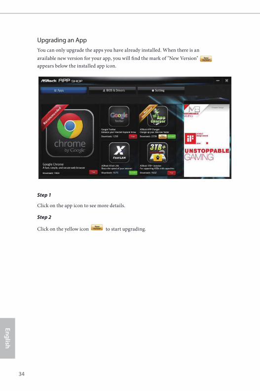
Upgrading an AppYou can only upgrade the apps you have already installed. When there is an available new version for your app, you will fi nd the mark of "New Version" appears below the installed app icon.
Step 1
Click on the app icon to see more details.
Step 2
Click on the yellow icon to start upgrading.
34 35
Engl
ish
H310CM-ITX/ac
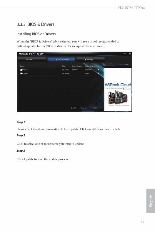
3.3.3 BIOS & Drivers
Installing BIOS or Drivers
When the "BIOS & Drivers" tab is selected, you will see a list of recommended or critical updates for the BIOS or drivers. Please update them all soon.
Step 1
Please check the item information before update. Click on to see more details.
Step 2
Click to select one or more items you want to update.
Step 3
Click Update to start the update process.
36 37
English
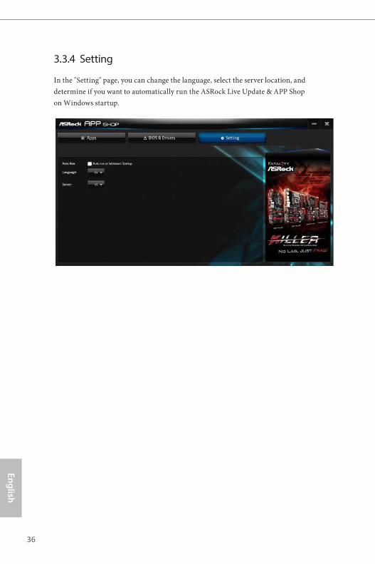
3.3.4 Setting
In the "Setting" page, you can change the language, select the server location, and determine if you want to automatically run the ASRock Live Update & APP Shop on Windows startup.
36 37
Engl
ish
H310CM-ITX/ac
Chapter 4 UEFI SETUP UTILITY
4.1 IntroductionThis section explains how to use the UEFI SETUP UTILITY to configure your system. You may run the UEFI SETUP UTILITY by pressing <F2> or <Del> right after you power on the computer, otherwise, the Power-On-Self-Test (POST) will continue with its test routines. If you wish to enter the UEFI SETUP UTILITY after POST, restart the system by pressing <Ctl> + <Alt> + <Delete>, or by pressing the reset button on the system chassis. You may also restart by turning the system off and then back on.
Because the UEFI software is constantly being updated, the following UEFI setup screens and descriptions are for reference purpose only, and they may not exactly match what you see on your screen.
38 39
English
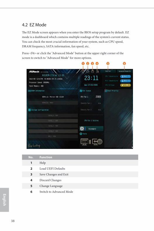
4.2 EZ ModeThe EZ Mode screen appears when you enter the BIOS setup program by default. EZ mode is a dashboard which contains multiple readings of the system’s current status. You can check the most crucial information of your system, such as CPU speed, DRAM frequency, SATA information, fan speed, etc.
Press <F6> or click the "Advanced Mode" button at the upper right corner of the screen to switch to "Advanced Mode" for more options.
No. Function
1 Help
2 Load UEFI Defaults
3 Save Changes and Exit
4 Discard Changes
5 Change Language
6 Switch to Advanced Mode

38 39
Engl
ish
H310CM-ITX/ac
4.3 Advanced ModeThe Advanced Mode provides more options to configure the BIOS settings. Refer to the following sections for the detailed configurations.
To access the EZ Mode, press <F6> or click the "EZ Mode" button at the upper right corner of the screen.
4.3.1 UEFI Menu Bar
The top of the screen has a menu bar with the following selections:
Main For setting system time/date information
OC Tweaker For overclocking configurations
Advanced For advanced system configurations
Tool Useful tools
H/W Monitor Displays current hardware status
Security For security settings
Boot For configuring boot settings and boot priority
Exit Exit the current screen or the UEFI Setup Utility
40 41
English
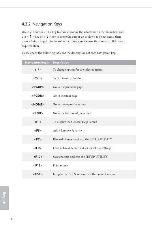
4.3.2 Navigation Keys
Use < > key or < > key to choose among the selections on the menu bar, and use < > key or < > key to move the cursor up or down to select items, then press <Enter> to get into the sub screen. You can also use the mouse to click your required item.
Please check the following table for the descriptions of each navigation key.
Navigation Key(s) Description
+ / - To change option for the selected items
<Tab> Switch to next function
<PGUP> Go to the previous page
<PGDN> Go to the next page
<HOME> Go to the top of the screen
<END> Go to the bottom of the screen
<F1> To display the General Help Screen
<F5> Add / Remove Favorite
<F7> Discard changes and exit the SETUP UTILITY
<F9> Load optimal default values for all the settings
<F10> Save changes and exit the SETUP UTILITY
<F12> Print screen
<ESC> Jump to the Exit Screen or exit the current screen
Use < > key or < > key to choose among the selections on the menu bar, and Use < > key or < > key to choose among the selections on the menu bar, and
40 41
Engl
ish
H310CM-ITX/ac
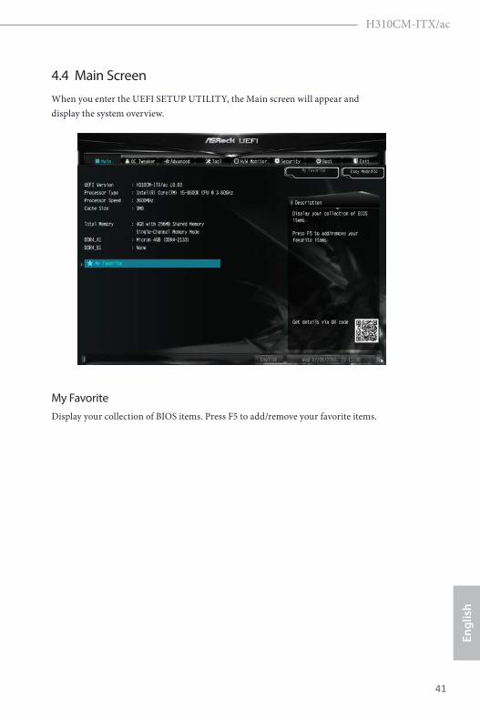
4.4 Main ScreenWhen you enter the UEFI SETUP UTILITY, the Main screen will appear and display the system overview.
My FavoriteDisplay your collection of BIOS items. Press F5 to add/remove your favorite items.
42 43
English
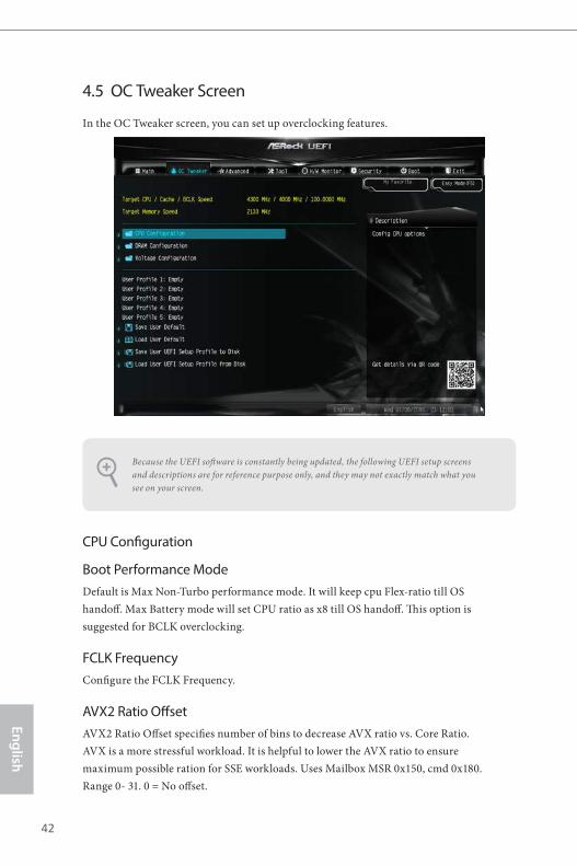
4.5 OC Tweaker Screen
In the OC Tweaker screen, you can set up overclocking features.
CPU Configuration
Boot Performance Mode Default is Max Non-Turbo performance mode. It will keep cpu Flex-ratio till OS handoff. Max Battery mode will set CPU ratio as x8 till OS handoff. This option is suggested for BCLK overclocking.
FCLK FrequencyConfigure the FCLK Frequency.
AVX2 Ratio OffsetAVX2 Ratio Offset specifies number of bins to decrease AVX ratio vs. Core Ratio. AVX is a more stressful workload. It is helpful to lower the AVX ratio to ensure maximum possible ration for SSE workloads. Uses Mailbox MSR 0x150, cmd 0x180. Range 0- 31. 0 = No offset.
Because the UEFI software is constantly being updated, the following UEFI setup screens and descriptions are for reference purpose only, and they may not exactly match what you see on your screen.
42 43
Engl
ish
H310CM-ITX/ac
BCLK Aware Adpative VoltageEnable or disable BCLK Aware Adaptive Voltage. When enabled, pcode will be aware of the BCLK frequency when calculating the CPU V/F curves. This is ideal for BCLK OC to avoid high voltage overrides.
Ring to Core Ratio Offset
Disable Ring to Core Ratio Offset so the ring and core can run at the same frequency.
Intel SpeedStep TechnologyIntel SpeedStep technology allows processors to switch between multiple frequen-cies and voltage points for better power saving and heat dissipation.
Intel Turbo Boost TechnologyIntel Turbo Boost Technology enables the processor to run above its base operating frequency when the operating system requests the highest performance state.
Intel Speed Shift TechnologyEnable/Disable Intel Speed Shift Technology support. Enabling will expose the CPPC v2 interface to allow for hardware controlled P-sates.
Long Duration Power LimitConfigure Package Power Limit 1 in watts. When the limit is exceeded, the CPU ratio will be lowered after a period of time. A lower limit can protect the CPU and save power, while a higher limit may improve performance.
Long Duration MaintainedConfigure the period of time until the CPU ratio is lowered when the Long Duration Power Limit is exceeded.
Short Duration Power LimitConfigure Package Power Limit 2 in watts. When the limit is exceeded, the CPU ratio will be lowered immediately. A lower limit can protect the CPU and save power, while a higher limit may improve performance.
CPU Core Current LimitConfigure the current limit of the CPU core. A lower limit can protect the CPU and save power, while a higher limit may improve performance.
GT Current LimitConfigure the current limit of the GT slice. A lower limit can protect the CPU and
44 45
English
save power, while a higher limit may improve performance.
GT FrequencyConfigure the frequency of the integrated GPU.
DRAM Configuration
DRAM Tweaker
Fine tune the DRAM settings by leaving marks in checkboxes. Click OK to confirm and apply your new settings.
DRAM Timing Configuration
DRAM Reference Clock
Select Auto for optimized settings.
DRAM FrequencyIf [Auto] is selected, the motherboard will detect the memory module(s) inserted and assign the appropriate frequency automatically.
DRAM ClockChoose a frequency to override to clock delay for memory training. DRAM Clock controls memory training only if ASRock Timing Optimization is disabled.
Primary Timing
CAS# Latency (tCL)
The time between sending a column address to the memory and the beginning of the data in response.
RAS# to CAS# Delay and Row Precharge (tRCDtRP) RAS# to CAS# Delay : The number of clock cycles required between the opening of a row of memory and accessing columns within it. Row Precharge: The number of clock cycles required between the issuing of the precharge command and opening the next row.
RAS# Active Time (tRAS)
The number of clock cycles required between a bank active command and issuing the precharge command.
Command Rate (CR)
The delay between when a memory chip is selected and when the first active command can
44 45
Engl
ish
H310CM-ITX/ac
be issued.
Secondary Timing
Write Recovery Time (tWR)The amount of delay that must elapse after the completion of a valid write operation, before an active bank can be precharged.
Refresh Cycle Time (tRFC)The number of clocks from a Refresh command until the first Activate command to the same rank.
RAS to RAS Delay (tRRD_L) The number of clocks between two rows activated in different banks of the same rank.
RAS to RAS Delay (tRRD_S)
The number of clocks between two rows activated in different banks of the same rank.
Write to Read Delay (tWTR_L)
The number of clocks between the last valid write operation and the next read command to the same internal bank.
Write to Read Delay (tWTR_S)
The number of clocks between the last valid write operation and the next read command to the same internal bank.
Read to Precharge (tRTP)The number of clocks that are inserted between a read command to a row pre-charge command to the same rank.
Four Activate Window (tFAW)The time window in which four activates are allowed the same rank.
CAS Write Latency (tCWL)Configure CAS Write Latency.
Third Timing
tREFIConfigure refresh cycles at an average periodic interval.
46 47
English
tCKEConfigure the period of time the DDR4 initiates a minimum of one refresh command internally once it enters Self-Refresh mode.
Turn Around Timing
tRDRD_sgConfigure between module read to read delay.
tRDRD_dgConfigure between module read to read delay.
tRDRD_drConfigure between module read to read delay.
tRDRD_ddConfigure between module read to read delay.
tRDWR_sgConfigure between module read to write delay.
tRDWR_dgConfigure between module read to write delay.
tRDWR_drConfigure between module read to write delay.
tRDWR_ddConfigure between module read to write delay.
tWRRD_sgConfigure between module write to read delay.
tWRRD_dgConfigure between module write to read delay.
tWRRD_drConfigure between module write to read delay.
tWRRD_ddConfigure between module write to read delay.

46 47
Engl
ish
H310CM-ITX/ac
tWRWR_sgConfigure between module write to write delay.
tWRWR_dgConfigure between module write to write delay.
tWRWR_drConfigure between module write to write delay.
tWRWR_ddConfigure between module write to write delay.
Round Trip Timing
RTL Init Value Configure round trip latency init value for round trip latency training.
IOL Init Value Configure IO latency init value for IO latency traning.
RTL (CH A) Configure round trip latency for channel A.
RTL (CH B)
Configure round trip latency for channel B.
IOL (CH A)
Configure IO latency for channel A.
IOL (CH B) Configure IO latency for channel B.
IOL Offset (CH A) Configure IO latency offset for channel A.
IOL Offset (CH B) Configure IO latency offset for channel B.
RFR Delay (CH A) Configure RFR Delay for Channel A.
48 49
English
RFR Delay (CH B)
Configure RFR Delay for Channel B.
ODT Setting
ODT WR (CH A)Configure the memory on die termination resistors' WR for channel A.
ODT PARK (CH A)Configure the memory on die termination resistors' PARK for channel A.
ODT NOM (CH A)Configure the memory on die termination resistors' NOM for channel A.
COMP Setting
RCOMP0: DQ ODT (Read)Default is 121.
RCOMP1: DQ /CLK Ron (Drive Strength)Default is 75.
RCOMP2: CMD /CTL Ron (Drive Strength)Default is 100.
DQ ODT DrivingAdjust DQ Driving for better signal. Default is 26.
DQ DrivingAdjust DQ Driving for better signal. Default is 26.
Command DrivingAdjust Command Driving for better signal. Default is 20.
Control DrivingAdjust Control Driving for better signal. Default is 20.
Clock DrivingAdjust Clock Driving for better signal. Default is 26.
48 49
Engl
ish
H310CM-ITX/ac
Slew Rate StageDelay PS of CompDqSlew Rate StageDelay PS of CompDq.
Slew Rate StageDelay PS of CompCmdSlew Rate StageDelay PS of CompCmd.
Slew Rate StageDelay PS of CompCtlSlew Rate StageDelay PS of CompCtl.
Slew Rate StageDelay PS of CompClkSlew Rate StageDelay PS of CompClk.
Dll Bandwidth 0Configure Dll Bandwidth 0 (1066 MHz) to maximize the performance of intergrated memory controller.
Dll Bandwidth 1Configure Dll Bandwidth 1 (1333 MHz) to maximize the performance of intergrated memory controller.
Dll Bandwidth 2Configure Dll Bandwidth 2 (1600 MHz) to maximize the performance of intergrated memory controller.
Dll Bandwidth 3Configure Dll Bandwidth 3 (1867 MHz) to maximize the performance of intergrated memory controller.
Advanced Setting
Realtime Memory TimingEnable/Disable realtime memory timings. When enabled, the system will allow performing realtime memory timing changes after MRC_DONE.
Command TristateUse this item to enable or disable Command Tristate support.
MRC Fast BootEnable Memory Fast Boot to skip DRAM memory training for booting faster.
50 51
English
Voltage Configuration
DRAM VoltageUse this to configure DRAM Voltage. The default value is [Auto].
PCH +1.05 VoltageConfigure the chipset voltage.
VCCST VoltageConfigure the voltage for the VCCST.
Save User DefaultType a profile name and press enter to save your settings as user default.
Load User DefaultLoad previously saved user defaults.
Save User UEFI Setup Profile to DiskSave current UEFI settings as an user default profile to disk.
Load User UEFI Setup Profile to DiskLoad previously saved user defaults from the disk.
50 51
Engl
ish
H310CM-ITX/ac
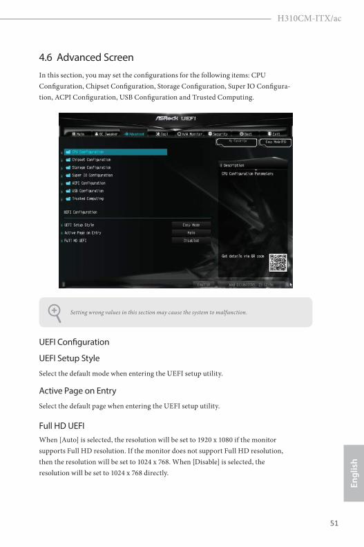
4.6 Advanced ScreenIn this section, you may set the configurations for the following items: CPU Configuration, Chipset Configuration, Storage Configuration, Super IO Configura-tion, ACPI Configuration, USB Configuration and Trusted Computing.
UEFI Configuration
UEFI Setup Style
Select the default mode when entering the UEFI setup utility.
Active Page on Entry
Select the default page when entering the UEFI setup utility.
Full HD UEFIWhen [Auto] is selected, the resolution will be set to 1920 x 1080 if the monitor supports Full HD resolution. If the monitor does not support Full HD resolution, then the resolution will be set to 1024 x 768. When [Disable] is selected, the resolution will be set to 1024 x 768 directly.
Setting wrong values in this section may cause the system to malfunction.
52 53
English
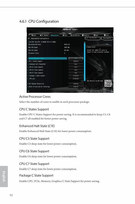
4.6.1 CPU Configuration
Active Processor CoresSelect the number of cores to enable in each processor package.
CPU C States SupportEnable CPU C States Support for power saving. It is recommended to keep C3, C6 and C7 all enabled for better power saving.
Enhanced Halt State (C1E)Enable Enhanced Halt State (C1E) for lower power consumption.
CPU C3 State SupportEnable C3 sleep state for lower power consumption.
CPU C6 State SupportEnable C6 sleep state for lower power consumption.
CPU C7 State SupportEnable C7 sleep state for lower power consumption.
Package C State Support
Enable CPU, PCIe, Memory, Graphics C State Support for power saving.
52 53
Engl
ish
H310CM-ITX/ac
CFG Lock
This item allows you to disable or enable the CFG Lock.
CPU Thermal ThrottlingEnable CPU internal thermal control mechanisms to keep the CPU from overheat-ing.
Intel Virtualization TechnologyIntel Virtualization Technology allows a platform to run multiple operating systems and applications in independent partitions, so that one computer system can function as multiple virtual systems.
Hardware PrefetcherAutomatically prefetch data and code for the processor. Enable for better performance.
Adjacent Cache Line PrefetchAutomatically prefetch the subsequent cache line while retrieving the currently requested cache line. Enable for better performance.
Software Guard Extensions (SGX)Use this item to enable or disable Software Controlled Software Guard Extensions (SGX).
54 55
English
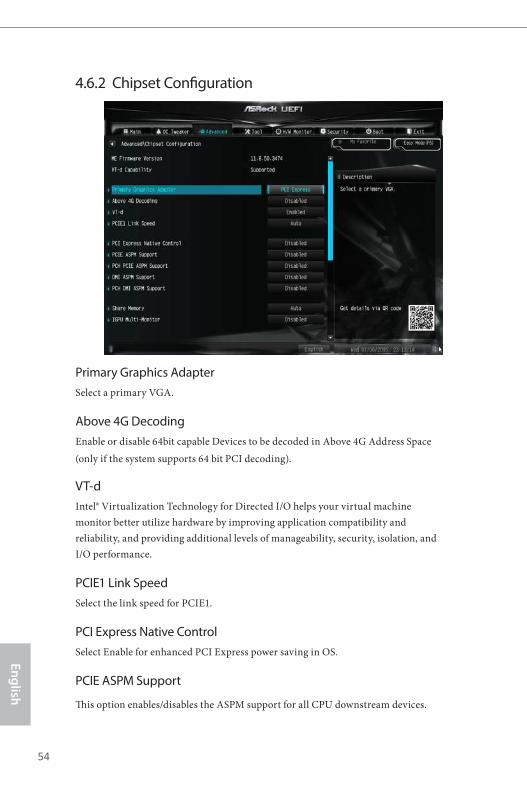
4.6.2 Chipset Configuration
Primary Graphics Adapter Select a primary VGA.
Above 4G DecodingEnable or disable 64bit capable Devices to be decoded in Above 4G Address Space (only if the system supports 64 bit PCI decoding).
VT-dIntel® Virtualization Technology for Directed I/O helps your virtual machine monitor better utilize hardware by improving application compatibility and reliability, and providing additional levels of manageability, security, isolation, and I/O performance.
PCIE1 Link SpeedSelect the link speed for PCIE1.
PCI Express Native ControlSelect Enable for enhanced PCI Express power saving in OS.
PCIE ASPM Support
This option enables/disables the ASPM support for all CPU downstream devices.
54 55
Engl
ish
H310CM-ITX/ac
PCH PCIE ASPM Support
This option enables/disables the ASPM support for all PCH PCIE devices.
DMI ASPM Support
This option enables/disables the control of ASPM on CPU side of the DMI Link.
PCH DMI ASPM Support
This option enables/disables the ASPM support for all PCH DMI devices.
Share Memory
Configure the size of memory that is allocated to the integrated graphics processor when the system boots up.
IGPU Multi-Monitor
Select disable to disable the integrated graphics when an external graphics card is installed. Select enable to keep the integrated graphics enabled at all times.
Intel(R) Ethernet Connection I219-V
Enable or disable the onboard network interface controller.
Onboard HD AudioEnable/disable onboard HD audio. Set to Auto to enable onboard HD audio and automatically disable it when a sound card is installed.
Front PanelEnable/disable front panel HD audio.
Onboard HDMI HD AudioEnable audio for the onboard digital outputs.
Onboard WAN DeviceUse this item to enable or disable the onboard WAN device.
WAN RadioEnable/disable the WiFi module's connectivity.
BluetoothEnable/disable the Bluetooth connectivity.

56 57
English
Deep SleepConfigure deep sleep mode for power saving when the computer is shut down.
Restore on AC/Power LossSelect the power state after a power failure. If [Power Off] is selected, the power will remain off when the power recovers. If [Power On] is selected, the system will start to boot up when the power recovers.
56 57
Engl
ish
H310CM-ITX/ac
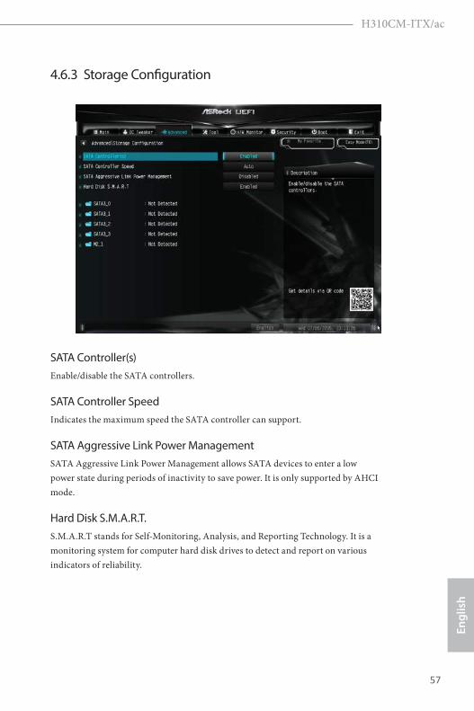
4.6.3 Storage Configuration
SATA Controller(s)Enable/disable the SATA controllers.
SATA Controller SpeedIndicates the maximum speed the SATA controller can support.
SATA Aggressive Link Power ManagementSATA Aggressive Link Power Management allows SATA devices to enter a low power state during periods of inactivity to save power. It is only supported by AHCI mode.
Hard Disk S.M.A.R.T. S.M.A.R.T stands for Self-Monitoring, Analysis, and Reporting Technology. It is a monitoring system for computer hard disk drives to detect and report on various indicators of reliability.
58 59
English
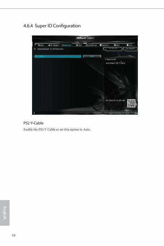
4.6.4 Super IO Configuration
PS2 Y-CableEnable the PS2 Y-Cable or set this option to Auto.
58 59
Engl
ish
H310CM-ITX/ac
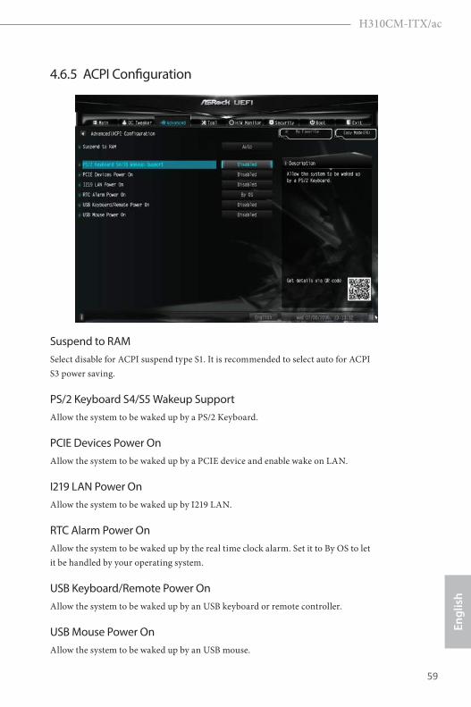
4.6.5 ACPI Configuration
Suspend to RAMSelect disable for ACPI suspend type S1. It is recommended to select auto for ACPI S3 power saving.
PS/2 Keyboard S4/S5 Wakeup SupportAllow the system to be waked up by a PS/2 Keyboard.
PCIE Devices Power OnAllow the system to be waked up by a PCIE device and enable wake on LAN.
I219 LAN Power OnAllow the system to be waked up by I219 LAN.
RTC Alarm Power OnAllow the system to be waked up by the real time clock alarm. Set it to By OS to let it be handled by your operating system.
USB Keyboard/Remote Power OnAllow the system to be waked up by an USB keyboard or remote controller.
USB Mouse Power OnAllow the system to be waked up by an USB mouse.
60 61
English
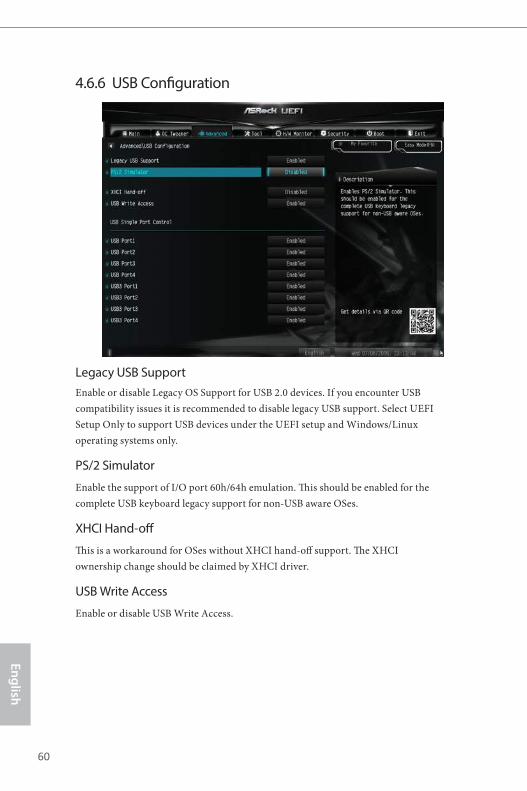
4.6.6 USB Configuration
Legacy USB SupportEnable or disable Legacy OS Support for USB 2.0 devices. If you encounter USB compatibility issues it is recommended to disable legacy USB support. Select UEFI Setup Only to support USB devices under the UEFI setup and Windows/Linux operating systems only.
PS/2 Simulator
Enable the support of I/O port 60h/64h emulation. This should be enabled for the complete USB keyboard legacy support for non-USB aware OSes.
XHCI Hand-off
This is a workaround for OSes without XHCI hand-off support. The XHCI ownership change should be claimed by XHCI driver.
USB Write Access
Enable or disable USB Write Access.
60 61
Engl
ish
H310CM-ITX/ac
4.6.7 Trusted Computing
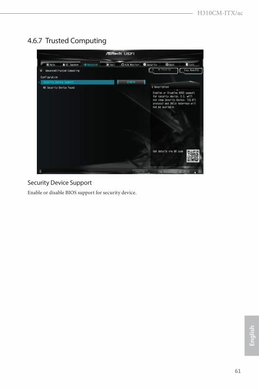
Security Device SupportEnable or disable BIOS support for security device.
62 63
English
4.7 Tools
UEFI Tech ServiceContact ASRock Tech Service if you are having trouble with your PC. Please setup network configuration before using UEFI Tech Service.
Instant Flash
Save UEFI files in your USB storage device and run Instant Flash to update your UEFI.
Internet Flash - DHCP (Auto IP), Auto
ASRock Internet Flash downloads and updates the latest UEFI firmware version from our servers for you. Please setup network configuration before using Internet Flash. *For BIOS backup and recovery purpose, it is recommended to plug in your USB pen drive before using this function.
62 63
Engl
ish
H310CM-ITX/ac
Network ConfigurationUse this to configure internet connection settings for Internet Flash.
Internet SettingEnable or disable sound effects in the setup utility.
UEFI Download ServerSelect a server to download the UEFI firmware.
64 65
English
4.8 Hardware Health Event Monitoring ScreenThis section allows you to monitor the status of the hardware on your system, including the parameters of the CPU temperature, motherboard temperature, fan speed and voltage.
Fan Tuning
Measure Fan Min Duty Cycle.
Fan-Tastic TuningSelect a fan mode for CPU Fans 1&2, or choose Customize to set 5 CPU temperatures and assign a respective fan speed for each temperature.
CPU Fan 1 SettingSelect a fan mode for CPU Fans, or choose Customize to set 5 CPU temperatures and assign a respective fan speed for each temperature.
CHA_FAN1 / W_PUMP SwitchSwitch CHA_FAN1 / WP header function
Chassis Fan 1 Control Mode
Select DC/PWM mode for Chassis Fan 1.
Chassis Fan 1 SettingSelect a fan mode for Chassis Fan, or choose Customize to set 5 CPU temperatures
64 65
Engl
ish
H310CM-ITX/ac
and assign a respective fan speed for each temperature.
Chassis Fan 1 Temp Source
Select a fan temperature source for Chassis Fan 1.
Chassis Fan 2 SettingSelect a fan mode for Fans, or choose Customize to set 5 CPU temperatures and assign a respective fan speed for each temperature.
Chassis Fan 2 Temp SourceSelect a fan temperature source for Chassis Fan 2.
Case Open FeatureEnable or disable Case Open Feature to detect whether the chassis cover has been removed.
66 67
English
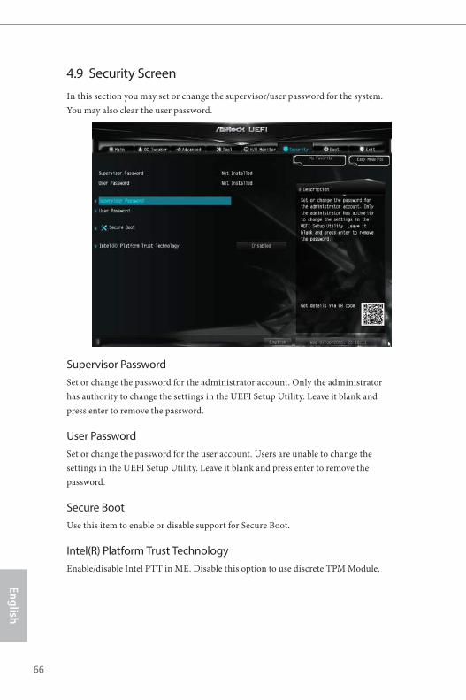
4.9 Security ScreenIn this section you may set or change the supervisor/user password for the system. You may also clear the user password.
Supervisor PasswordSet or change the password for the administrator account. Only the administrator has authority to change the settings in the UEFI Setup Utility. Leave it blank and press enter to remove the password.
User PasswordSet or change the password for the user account. Users are unable to change the settings in the UEFI Setup Utility. Leave it blank and press enter to remove the password.
Secure BootUse this item to enable or disable support for Secure Boot.
Intel(R) Platform Trust TechnologyEnable/disable Intel PTT in ME. Disable this option to use discrete TPM Module.
66 67
Engl
ish
H310CM-ITX/ac
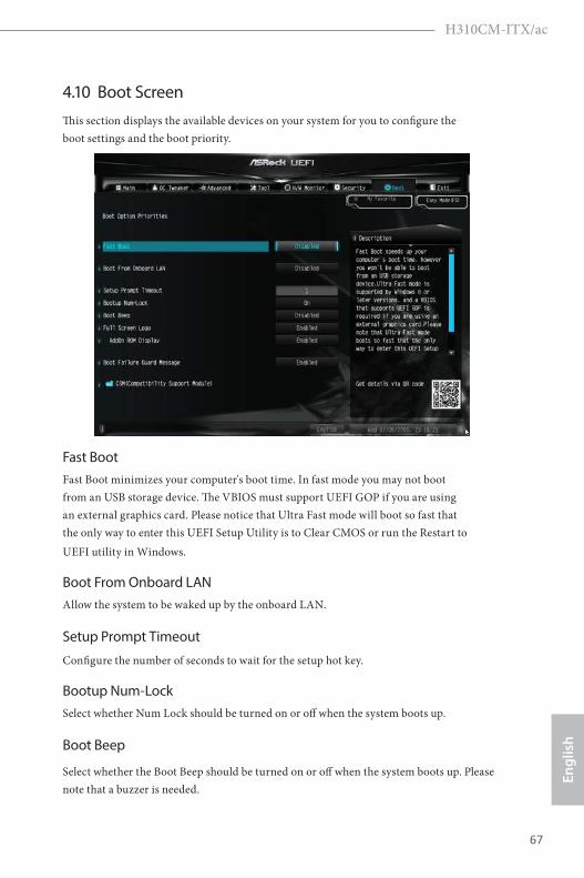
4.10 Boot ScreenThis section displays the available devices on your system for you to configure the boot settings and the boot priority.
Fast Boot Fast Boot minimizes your computer's boot time. In fast mode you may not boot from an USB storage device. The VBIOS must support UEFI GOP if you are using an external graphics card. Please notice that Ultra Fast mode will boot so fast that the only way to enter this UEFI Setup Utility is to Clear CMOS or run the Restart to UEFI utility in Windows.
Boot From Onboard LANAllow the system to be waked up by the onboard LAN.
Setup Prompt Timeout
Configure the number of seconds to wait for the setup hot key.
Bootup Num-LockSelect whether Num Lock should be turned on or off when the system boots up.
Boot Beep
Select whether the Boot Beep should be turned on or off when the system boots up. Please note that a buzzer is needed.

68 69
English
Full Screen LogoEnable to display the boot logo or disable to show normal POST messages.
AddOn ROM DisplayEnable AddOn ROM Display to see the AddOn ROM messages or configure the AddOn ROM if you've enabled Full Screen Logo. Disable for faster boot speed.
Boot Failure Guard MessageIf the computer fails to boot for a number of times the system automatically restores the default settings.
CSM (Compatibility Support Module)
CSM Enable to launch the Compatibility Support Module. Please do not disable unless you’re running a WHCK test.
Launch PXE OpROM Policy Select UEFI only to run those that support UEFI option ROM only. Select Legacy only to run those that support legacy option ROM only. Select Do not launch to not execute both legacy and UEFI option ROM.
68 69
Engl
ish
H310CM-ITX/ac
Launch Storage OpROM PolicySelect UEFI only to run those that support UEFI option ROM only. Select Legacy only to run those that support legacy option ROM only. Select Do not launch to not execute both legacy and UEFI option ROM.
Other PCI Device ROM PriorityFor PCI devices other than Network. Mass storage or Video defines which OpROM-to launch.
70 71
English
4.11 Exit Screen
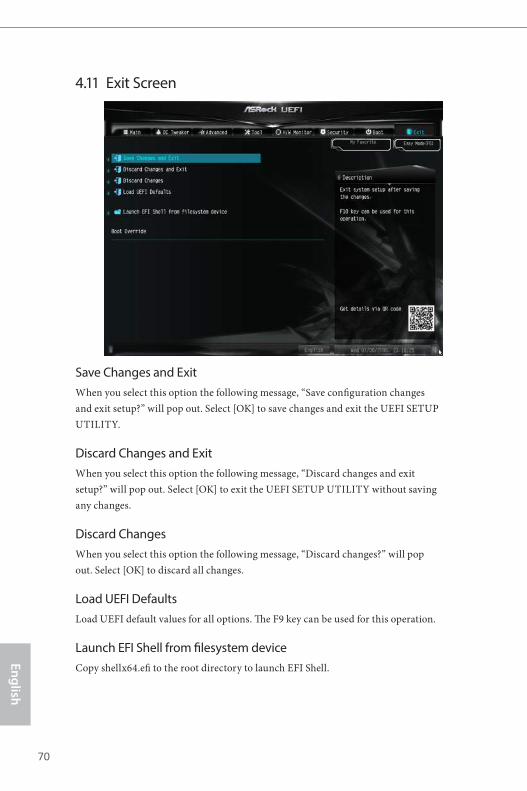
Save Changes and ExitWhen you select this option the following message, “Save configuration changes and exit setup?” will pop out. Select [OK] to save changes and exit the UEFI SETUP UTILITY.
Discard Changes and ExitWhen you select this option the following message, “Discard changes and exit setup?” will pop out. Select [OK] to exit the UEFI SETUP UTILITY without saving any changes.
Discard ChangesWhen you select this option the following message, “Discard changes?” will pop out. Select [OK] to discard all changes.
Load UEFI DefaultsLoad UEFI default values for all options. The F9 key can be used for this operation.
Launch EFI Shell from filesystem deviceCopy shellx64.efi to the root directory to launch EFI Shell.

Contact Information
If you need to contact ASRock or want to know more about ASRock, you’re welcome to visit ASRock’s website at http://www.asrock.com; or you may contact your dealer for further information. For technical questions, please submit a support request form at https://event.asrock.com/tsd.asp
ASRock Incorporation2F., No.37, Sec. 2, Jhongyang S. Rd., Beitou District,
Taipei City 112, Taiwan (R.O.C.)
ASRock EUROPE B.V.Bijsterhuizen 11-11
6546 AR Nijmegen
The Netherlands
Phone: +31-24-345-44-33
Fax: +31-24-345-44-38
ASRock America, Inc.13848 Magnolia Ave, Chino, CA91710
U.S.A.
Phone: +1-909-590-8308
Fax: +1-909-590-1026
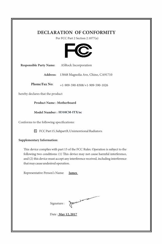
DECLARATION OF CONFORMITY
Per FCC Part 2 Section 2.1077(a)
Responsible Party Name: ASRock Incorporation
Address: 13848 Magnolia Ave, Chino, CA91710
+1-909-590-8308/+1-909-590-1026
Phone/Fax No:
hereby declares that the product
Product Name : Motherboard
Model Number :
Conforms to the following speci�cations:
FCC Part 15, Subpart B, Unintentional Radiators
Supplementary Information:
�is device complies with part 15 of the FCC Rules. Operation is subject to the following two conditions: (1) �is device may not cause harmful interference, and (2) this device must accept any interference received, including interference that may cause undesired operation. Representative Person’s Name: James
Signature :
Date : May 12, 2017
H310CM-ITX/ac

EU Declaration of Conformity For the following equipment:
Motherboard(Product Name)
H310CM-ITX/ac / ASRock(Model Designation / Trade Name)
ASRock Incorporation(Manufacturer Name)
2F., No.37, Sec. 2, Jhongyang S. Rd., Beitou District, Taipei City 112, Taiwan (R.O.C.)(Manufacturer Address)
ASRock EUROPE B.V.(Company Name)
Bijsterhuizen 1111 6546 AR Nijmegen The Netherlands(Company Address)
Person responsible for making this declaration:
(Name, Surname)A.V.P(Position / Title)October 12, 2018(Date)
P/N: 15G062127000AK V1.0
EMC —Directive 2014/30/EU (from April 20th, 2016) ☐ EN 55022:2010/AC:2011 Class B EN 55024:2010/A1:2015
EN 55032:2012+AC:2013 Class B EN 61000-3-3:2013 EN 61000-3-2:2014
RED—Directive 2014/53/EU EN 300 328 V2.1.1 EN 301 489-17 V3.1.1
☐☐
☐☐
EN 301 893 V2.1.1 ☐ EN 301 489-3 V2.1.1 ☐ EN 300 220 V3.1.1
LVD —Directive 2014/35/EU (from April 20th, 2016) EN 60950-1 : 2011+ A2: 2013 ☐ EN 60950-1 : 2006/A12: 2011
RoHS — Directive 2011/65/EU CE marking
(EU conformity marking)