versatile rotary actuator device vrad 1510 series
TRANSCRIPT
Versatile Rotary Actuator Device VRAD 1510 series
(licenses available for manufacturing)
Document Number: VRAD-1510-9019 www.ScannerMAX.com Revision: 25-September-2018
1
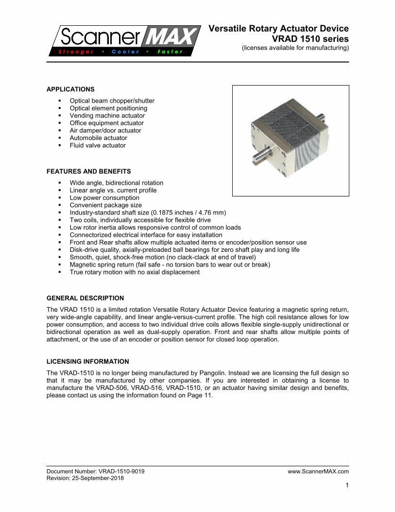
APPLICATIONS
Optical beam chopper/shutter Optical element positioning Vending machine actuator Office equipment actuator Air damper/door actuator Automobile actuator Fluid valve actuator
FEATURES AND BENEFITS
Wide angle, bidirectional rotation Linear angle vs. current profile Low power consumption Convenient package size Industry-standard shaft size (0.1875 inches / 4.76 mm) Two coils, individually accessible for flexible drive Low rotor inertia allows responsive control of common loads Connectorized electrical interface for easy installation Front and Rear shafts allow multiple actuated items or encoder/position sensor use Disk-drive quality, axially-preloaded ball bearings for zero shaft play and long life Smooth, quiet, shock-free motion (no clack-clack at end of travel) Magnetic spring return (fail safe - no torsion bars to wear out or break) True rotary motion with no axial displacement
GENERAL DESCRIPTION
The VRAD 1510 is a limited rotation Versatile Rotary Actuator Device featuring a magnetic spring return, very wide-angle capability, and linear angle-versus-current profile. The high coil resistance allows for low power consumption, and access to two individual drive coils allows flexible single-supply unidirectional or bidirectional operation as well as dual-supply operation. Front and rear shafts allow multiple points of attachment, or the use of an encoder or position sensor for closed loop operation. LICENSING INFORMATION
The VRAD-1510 is no longer being manufactured by Pangolin. Instead we are licensing the full design so that it may be manufactured by other companies. If you are interested in obtaining a license to manufacture the VRAD-506, VRAD-516, VRAD-1510, or an actuator having similar design and benefits, please contact us using the information found on Page 11.

Versatile Rotary Actuator Device VRAD 1510 series
(licenses available for manufacturing)
Document Number: VRAD-1510-9019 www.ScannerMAX.com Revision: 25-September-2018
2
SPECIFICATIONS
Parameter Value Units
Rotation angle (1)
+/- 45 Mechanical degrees peak-to-peak
Torque Factor (2)
1,500,000 Dyne*Centimeters per amp (coils in series)
Magnetic Spring Stiffness (3)
10,700 Dyne*Centimeters per degree
Rotor Inertia 0.5 Gram*Centimeters2
Natural Frequency (4)
185 Hz
Coil Resistance (5)
56 Ohms (coils in series)
Coil Inductance (5)
175 MilliHenry at 1kHz (coils in series)
Maximum Current (6)
2.0 Amps per coil
Angle vs. Current Linearity 95 % over +/- 45 degrees peak-to-peak
Angle vs. Current Sensitivity (7)
7 Milliamps per degree (coils in series)
Temperature coefficient of sensitivity +0.14 % per °C
Angular position hysteresis +/- 1 Mechanical degrees maximum
Maximum internal temperature (8)
80 °C
Thermal Resistance with heatsink (9)
7.6 °C per watt
Thermal resistance without heatsink 12.0 °C per watt
DC Power at +/- 15 degrees 0.64 Watts (6 volts series; 3 volts parallel)
DC Power at +/- 30 degrees 2.57 Watts (12 volts series; 6 volts parallel)
DC Power at +/- 45 degrees 5.78 Watts (18 volts series; 9 volts parallel)
DC Power at +/- 60 degrees 10.28 Watts (24 volts series; 12 volts parallel)
Dielectric Strength 1000 VRMS
Life cycles (10)
1010
Cycles
Mass 180 Grams
NOTES
1. There is no mechanical stop mechanism preventing further rotation, and the actuator may be used with angles beyond +/- 60 mechanical degrees with some sacrifice in angle-versus-current linearity.
2. Torque Factor depends on the shaft rotation angle. See the section on Torque production. 3. Magnetic spring stiffness depends on the shaft rotation angle and the model of the actuator, and
is easily customizable. See the section on Magnetic Spring Return. 4. Since Magnetic Spring Stiffness depends on angle, Natural Frequency also has some minor
dependence on angle. Natural frequency is thus specified for small angles. 5. Coil resistance and inductance depend on whether coils are connected in series, in parallel, or
used independently. See the section on Coil Resistance and Inductance. 6. This is a limitation imposed by the connector, and it assumes that AWG #24 wire is crimped into
each terminal. This current is derated to 0.5A if AWG #30 wire is crimped instead. 7. Angle vs. Current operation assumes that there is no static load and that the actuator is merely
used to move a flag, mirror, or other element suspended from the actuator shaft. 8. Maximum internal temperature of the actuator specified for commercial-grade units. Industrial-
grade units are available whose temperature can exceed 100° C. 9. Heat sink must be attached to the front of the actuator to meet the specification above. 10. Life cycles are only limited by bearing life. Bearings are high quality disk drive grade.
Specifications are at a temperature of 25° C. All mechanical and electrical specifications are +/-10%.
Versatile Rotary Actuator Device VRAD 1510 series
(licenses available for manufacturing)
Document Number: VRAD-1510-9019 www.ScannerMAX.com Revision: 25-September-2018
3
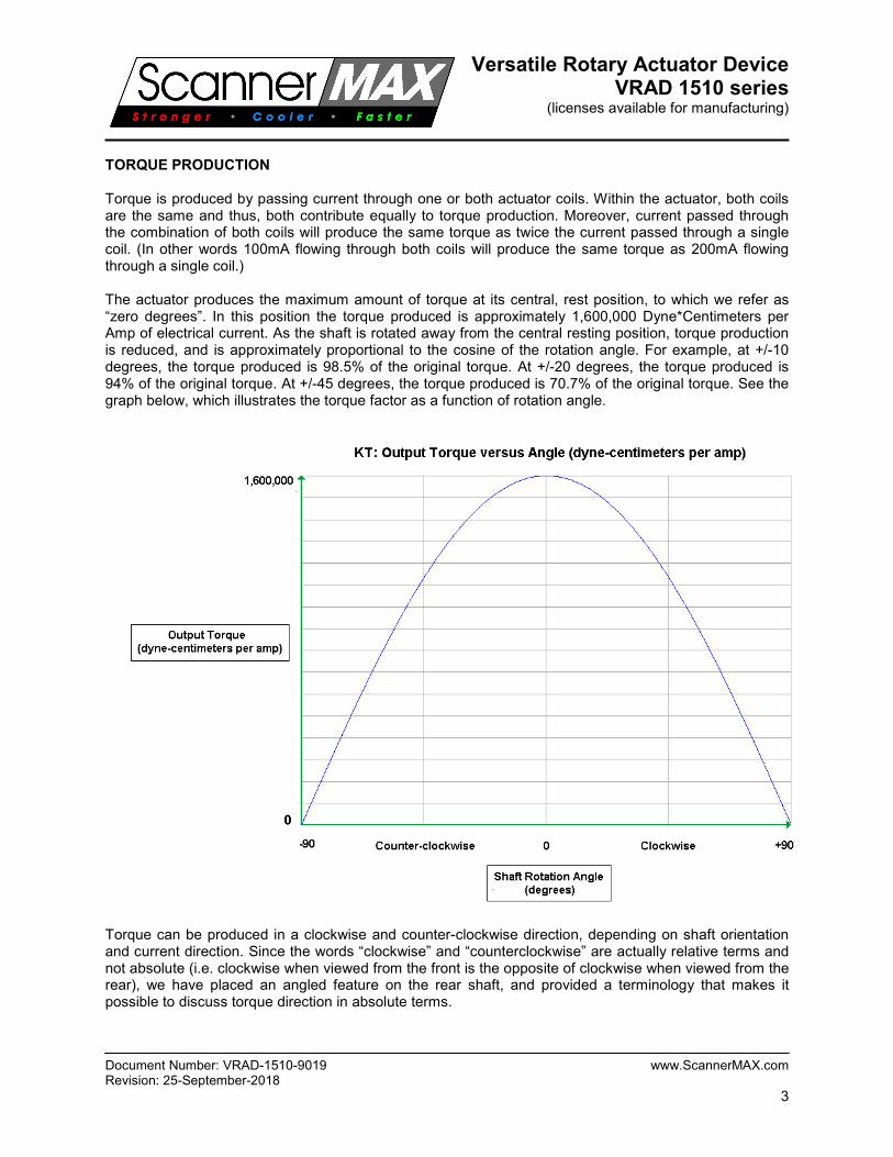
TORQUE PRODUCTION Torque is produced by passing current through one or both actuator coils. Within the actuator, both coils are the same and thus, both contribute equally to torque production. Moreover, current passed through the combination of both coils will produce the same torque as twice the current passed through a single coil. (In other words 100mA flowing through both coils will produce the same torque as 200mA flowing through a single coil.) The actuator produces the maximum amount of torque at its central, rest position, to which we refer as “zero degrees”. In this position the torque produced is approximately 1,600,000 Dyne*Centimeters per Amp of electrical current. As the shaft is rotated away from the central resting position, torque production is reduced, and is approximately proportional to the cosine of the rotation angle. For example, at +/-10 degrees, the torque produced is 98.5% of the original torque. At +/-20 degrees, the torque produced is 94% of the original torque. At +/-45 degrees, the torque produced is 70.7% of the original torque. See the graph below, which illustrates the torque factor as a function of rotation angle.
Torque can be produced in a clockwise and counter-clockwise direction, depending on shaft orientation and current direction. Since the words “clockwise” and “counterclockwise” are actually relative terms and not absolute (i.e. clockwise when viewed from the front is the opposite of clockwise when viewed from the rear), we have placed an angled feature on the rear shaft, and provided a terminology that makes it possible to discuss torque direction in absolute terms.

Versatile Rotary Actuator Device VRAD 1510 series
(licenses available for manufacturing)
Document Number: VRAD-1510-9019 www.ScannerMAX.com Revision: 25-September-2018
4
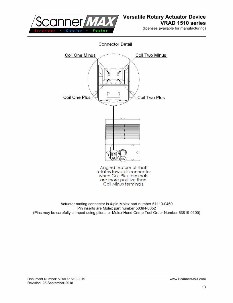
When current is flowing through the coils such that the plus terminals on the connector is more positive than the minus terminals, the feature on the rear shaft will rotate in the direction of the connector. See the figure on page 14 for clarification. MAGNETIC SPRING RETURN The actuator features a magnetic spring return, which provides torque in the direction that will restore the rotor to its central resting position. There are two ways to describe the restoration torque – in absolute terms, or in relative terms. In absolute terms, the magnetic spring return is providing zero torque when the rotor is in its central resting position. As you rotate the shaft clockwise a few degrees, the magnetic spring return will produce torque in a counterclockwise direction. As you rotate the shaft a few degrees more, the magnetic spring return will produce even more torque. Torque produced by the magnetic spring return tends to be approximately sinusoidal in nature, and is at its maximum when the rotor is in the +/-45 degree positions. Further rotation of the shaft beyond +/-45 still produces a restoration torque, but the amount of torque decreases until the shaft is in the +/-90 degree positions, at which point no restoration torque is provided by the magnetic spring return. The graph below illustrates the restoration torque in absolute terms.

Versatile Rotary Actuator Device VRAD 1510 series
(licenses available for manufacturing)
Document Number: VRAD-1510-9019 www.ScannerMAX.com Revision: 25-September-2018
5
There is another way to describe the magnetic spring return, and that is in relative terms – dyne centimeters of torque per degree of rotation, which may also be called “spring rate”. If you rotate the shaft clockwise by 1 degree, the restoration torque is approximately 10,000 Dyne*Centimeters. If you rotate the shaft clockwise by 2 degrees, the restoration torque is approximately 20,000 Dyne*Centimeters. If you rotate the shaft by 10 degrees, the restoration torque is approximately 100,000 Dyne*Centimeters. Thus, in relative terms, the restoration torque (spring rate) is approximately 10,000 Dyne*Centimeters per degree for small angles. As the angle increases, the restoration torque per degree decreases, and is approximately proportional to the cosine of the rotation angle. For example, at +/-10 degrees, the restoration torque spring rate is 98.5% of the original rate. At +/-20 degrees, the torque spring rate is 94% of the original rate. At +/-45 degrees, the torque spring rate is 70.7% of the original rate. See the chart below, which illustrates the restoration torque in relative terms.
Note that we can easily modify the amount of restoration torque produced by the magnetic spring return and thus, actuators can be manufactured which produce the same torque, but have reduced magnetic spring return action. Such actuators will provide a greater amount or rotation with less input electrical current. This may be desirable in low power applications. Please specify the amount of restoration torque when you place your order.

Versatile Rotary Actuator Device VRAD 1510 series
(licenses available for manufacturing)
Document Number: VRAD-1510-9019 www.ScannerMAX.com Revision: 25-September-2018
6
COIL RESISTANCE AND INDUCTANCE Each coil has a resistance of approximately 28 ohms. The series combination of coils has a resistance of approximately 56 ohms. Thus, applying 6 volts to the series combination of coils will consume only 107mA of current. Each coil has an inductance of approximately 60 millihenry, but this will only be observed if one coil is used and one coil is completely disconnected. There is strong mutual inductance between the two coils. Short circuiting the second coil will reflect an inductance in the first coil of 48 milliHenry at 1kHz. Due to the strong mutual inductance between the two coils, the series combination of coils has nearly three times the inductance of a single coil, not twice the inductance as would be the case with two inductors having no mutual inductance. Thus, the inductance of the series combination of two coils is 175 milliHenry at 1kHz. The parallel combination of two coils is 45 milliHenry at 1kHz. We have developed a Faraday Shield approach, which may optionally be added to the actuator. When this is done, it reduces the apparent inductance of a single coil to 8 milliHenry at 1kHz, and reduces the inductance of the series combination of coils to 15 milliHenry at 1kHz. The Faraday Shield also provides damping to the motion of the actuator. This may provide a simple way of eliminating overshoot, when using heavy loads and driving the actuator with a pure current (instead of a voltage). Note that within this actuator design, the inductance does not change very much as the rotation angle is changed, and thus, there is almost no “inductance modulation”. EQUIVALENT CIRCUIT The equivalent circuit of the actuator with two coils connected in series is shown below.
RS is the series resistance of the copper coils L is the inductance of the magnetic circuit C is the capacitance caused by the layers of wire that form the coils RP is the equivalent parallel resistance caused by the interaction of the coil and actuator materials
For the standard VRAD-1510 actuator, the values are: RS = 56 Ω; L = 175 mH; C= 16pF; RP = 100K Ω.
When the Faraday Shields are installed, the values are RS=270 Ω; L=8mH; C=21pF; RP=150K Ω.

Versatile Rotary Actuator Device VRAD 1510 series
(licenses available for manufacturing)
Document Number: VRAD-1510-9019 www.ScannerMAX.com Revision: 25-September-2018
7
ACTUATOR LINEARITY AND SENSITIVITY Since the torque versus angle profile is approximately proportional to the cosine of rotor angle, and also since the magnetic spring restoration torque versus angle profile is also approximately proportional to the cosine of rotor angle, these two cosines curves cancel out (as long as there is no static load on the rotor). Because of this, the angle versus current profile for this actuator is almost completely linear, even over very large angles greater than +/- 60 degrees! The graph below shows actual measured linearity for various coil voltages.
With the coils connected in series and no static load attached to the shaft, the coil resistance is approximately 56 ohms, and motion provided is approximately 2.5 degrees per volt, resulting in the following:
• 15 degrees at 6 volts (107mA; 0.64 watts)
• 30 degrees at 12 volts (214mA; 2.57 watts)
• 45 degrees at 18 volts (321mA; 5.78 watts)
• 60 degrees at 24 volts (428mA; 10.28 watts) With the coils connected in parallel, the coil resistance is approximately 14 ohms, and motion provided is approximately 5 degrees per volt, resulting in the following:
• 30 degrees at 6 volts (428mA; 2.57 watts)
• 60 degrees at 12 volts (856mA; 10.28 watts) Angles stated above are in EACH DIRECTION, not the peak-to-peak value of both directions. SENSITIVITY DEPENDENCE ON TEMPERATURE As the internal temperature of the actuator rises, the flux density produced by the magnet decreases. This reduces the magnetic spring return effect faster than it reduces the torque factor. As a result, the angle versus current actually increases a bit (at a rate of 0.14% per degree C) as temperature increases. However, the resistance of the copper coil increases faster than the magnetic phenomenon, and thus the angle versus voltage decreases a bit (at a rate of 0.32% per degree C) as temperature increases. Therefore the angular sensitivity versus temperature will depend on whether the actuator is driven with a pure current or with a pure voltage.
Versatile Rotary Actuator Device VRAD 1510 series
(licenses available for manufacturing)
Document Number: VRAD-1510-9019 www.ScannerMAX.com Revision: 25-September-2018
8
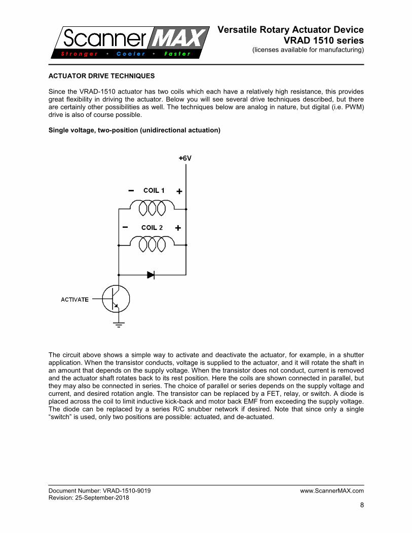
ACTUATOR DRIVE TECHNIQUES Since the VRAD-1510 actuator has two coils which each have a relatively high resistance, this provides great flexibility in driving the actuator. Below you will see several drive techniques described, but there are certainly other possibilities as well. The techniques below are analog in nature, but digital (i.e. PWM) drive is also of course possible. Single voltage, two-position (unidirectional actuation)
The circuit above shows a simple way to activate and deactivate the actuator, for example, in a shutter application. When the transistor conducts, voltage is supplied to the actuator, and it will rotate the shaft in an amount that depends on the supply voltage. When the transistor does not conduct, current is removed and the actuator shaft rotates back to its rest position. Here the coils are shown connected in parallel, but they may also be connected in series. The choice of parallel or series depends on the supply voltage and current, and desired rotation angle. The transistor can be replaced by a FET, relay, or switch. A diode is placed across the coil to limit inductive kick-back and motor back EMF from exceeding the supply voltage. The diode can be replaced by a series R/C snubber network if desired. Note that since only a single “switch” is used, only two positions are possible: actuated, and de-actuated.

Versatile Rotary Actuator Device VRAD 1510 series
(licenses available for manufacturing)
Document Number: VRAD-1510-9019 www.ScannerMAX.com Revision: 25-September-2018
9
Single voltage, three-position (bidirectional actuation)
The circuit above shows a simple way to command the actuator to rotate either clockwise or counterclockwise. When the left-most transistor conducts, voltage is supplied to one coil in the actuator, which (depending on shaft orientation) may force the actuator to rotate clockwise. When the right-most transistor conducts, voltage is supplied to another coil in the actuator which may force the actuator to rotate counterclockwise. When neither transistor conducts, current is removed and the actuator shaft rotates back to its central rest position. The amount of rotation is dictated by the supply voltage. As was the case above, the transistor can be replaced by a FET, relay, or switch. A diode is placed across each coil to limit inductive kick-back and motor back EMF from exceeding the supply voltage. The diode can be replaced by a series R/C snubber network if desired. Dual voltage, variable position (bidirectional actuation)
The circuit above shows a way to accomplish variable position control. Here two supply voltages feed transistors which then supply voltage to the actuator. The amount of voltage supplied by the transistors will dictate the angle and direction of the actuator. The transistors and diodes in the shaded area may be implemented as a Power Op-amp. Note that variable position is also possible with a single supply, using an H-Bridge technique. In such a case, four transistors (or two Power Op-amps) are used, and the actuator coil is connected between the two. Here the coils are shown connected in series, but they may also be connected in parallel. The choice of parallel or series depends on the supply voltage and current, and desired rotation angle.

Versatile Rotary Actuator Device VRAD 1510 series
(licenses available for manufacturing)
Document Number: VRAD-1510-9019 www.ScannerMAX.com Revision: 25-September-2018
10
Using one coil for drive, and the second for velocity or damping control Since both coils offer the same torque production capability, and since a single coil offers the same torque capability as two coils (albeit at twice the current), this raises the possibility that one coil may be used for a purpose other than torque production, such as for velocity sensing or dynamic braking. For example, a resistor may be connected across the second coil and the value of the resistor may be adjusted to control the amount of dynamic braking (damping). Note that when using the second coil for velocity sensing, drive current in the first coil will need to be electronically removed, due to the strong mutual inductance between the two coils. SHAFT USAGE The actuator features a front shaft and rear shaft. Each shaft can be used for actuation or to attach an encoder or position sensor. As mentioned above, there is a magnetic return spring that is a feature of this actuator. Although this magnetic spring return provides torque that tends to rotate the rotor back to a central rest position, there is nothing preventing the shaft from being rotated all the way around. In fact this could be a benefit. Two actuators may be used together and shafts can be oriented 90 degrees to one another, forming a two-phase continuous rotation motor. Nevertheless, if the possibility of continuous rotation is not desired, and if you are driving heavy inertial loads over angles greater than approximately +/-40 degrees, and if you are driving those heavy inertial loads very quickly, it may be necessary to implement an external stop mechanism. Such a mechanism may be attached to one of the shafts. Note that standard actuator features an axial preload, which is a spring pushing toward the front, from the rear of the actuator. When the actuator is oriented such that the shafts are arranged vertically, and when driving loads that have variable axial force or loads whose weight is greater than approximately 0.25 pounds (approximately 120 grams), it is recommended that the front shaft be oriented downward, toward the ground, which will add additional force to the bearing preload, rather than removing preload. We can also easily modify the actuator to provide two preload springs, allowing the actuator shafts to float. This would be desirable if the actuator is attached to another rotating shaft (such as a second actuator). We can also modify the actuator to use a radial preload instead of an axial preload. Please contact ScannerMAX for information about customization.

Versatile Rotary Actuator Device VRAD 1510 series
(licenses available for manufacturing)
Document Number: VRAD-1510-9019 www.ScannerMAX.com Revision: 25-September-2018
11
PART NUMBERING SCHEME The part numbering scheme was developed as a tool for customers to completely specify individual actuator elements. Each element is separated by a dash. Typical part number: VRAD-15x10x15-1.5-10-2x28-175-187x0.5-187x0.5-AR0.5-C Part number element definitions: VRAD (Versatile Rotary Actuator Device series) Width x Height x Depth (specified in tenths of an inch) Torque Factor (specified in Millions of Dyne*CM per Amp) Magnetic Spring Stiffness (specified in Thousands of Dyne*CM per mechanical degree) Number of coils and resistance per coil (specified in ohms) Inductance of all coils in series (specified in millihenry tested at 1kHz) Front Shaft diameter and length (diameter specified thousandths, length in inches) Rear shaft diameter and length (diameter specified thousandths, length in inches) Bearing preload configuration (A=axial, D=radial, N=none, R=from rear, F=from front, # in pounds) Temperature range (C = Commercial, I = Industrial) Note that we can customize each of these elements for individual applications. Please contact us if you have special requirements not met by the standard actuator. MORE INFORMATION
More information about the Versatile Rotary Actuator, including additional application hints and tips can be found on the ScannerMAX web site at www.ScannerMAX.com. In addition, OEMs are strongly encouraged to work with us to make sure that the most appropriate actuator is chosen and designed-in.
PATENT AND TRADEMARK INFORMATION
US Utility Patent Number: 8,963,396 US Utility Patent Number: 9,077,219 German Patent (Utility Model) Number: 20 2012 009 275.8 Chinese Patent No. ZL201210363949.9 Chinese Patent No. ZL201210363955.4 Other US and International Patents Pending.
ScannerMAX, Versatile Rotary Actuator Device and VRAD are trademarks of Pangolin Laser Systems.
U.S. Headquarters: Central Europe Branch Office: Pangolin Laser Systems, Inc. Pangolin d.o.o. 9501 Satellite Boulevard, Suite 109 Podutiška cesta 75 Orlando, FL 32837 – USA 1000 Ljubljana, SLOVENIA Phone: +1-407-299-2088 Phone: +386-1-517-4270 Fax: +1-407-299-6066 Fax: +386-1-517-4275

Versatile Rotary Actuator Device VRAD 1510 series
(licenses available for manufacturing)
Document Number: VRAD-1510-9019 www.ScannerMAX.com Revision: 25-September-2018
12
PHYSICAL DIMENSIONS
Versatile Rotary Actuator Device VRAD 1510 series
(licenses available for manufacturing)
Document Number: VRAD-1510-9019 www.ScannerMAX.com Revision: 25-September-2018
13
Actuator mating connector is 4-pin Molex part number 51110-0460 Pin inserts are Molex part number 50394-8052
(Pins may be carefully crimped using pliers, or Molex Hand Crimp Tool Order Number 63819-0100)