versaline track system - 2mm.org.uk · pdf fileversaline track system ... 1-132...
TRANSCRIPT
Versaline Track System
BUILDER’S GUIDE S1-301

Versaline Chairplate System: Builder’s Guide
Contents
INTRODUCTION ................................................................................................................................ 1 JIGS ....................................................................................................................................................... 1 USE OF TEMPLATES ........................................................................................................................ 2 PRELIMINARIES................................................................................................................................ 2
SOLDERING.............................................................................................................................................................................2 PLAIN TRACK .................................................................................................................................... 4
ASSEMBLY..............................................................................................................................................................................4 JOINTS WITH WIDE SLEEPERS.................................................................................................................................................4 FISHPLATES ............................................................................................................................................................................4
STANDARD TURNOUTS................................................................................................................... 5 TIMBERING .............................................................................................................................................................................5 PREPARATION.........................................................................................................................................................................6 SWITCHES...............................................................................................................................................................................7 CROSSING...............................................................................................................................................................................7 CLOSURE RAILS......................................................................................................................................................................8
OTHER TURNOUTS........................................................................................................................... 9 ‘C’ SWITCH TURNOUTS ..........................................................................................................................................................9 CURVED TURNOUTS ...............................................................................................................................................................9 TANDEM TURNOUTS...............................................................................................................................................................9
DIAMONDS AND SLIPS .................................................................................................................. 10 PREPARATION.......................................................................................................................................................................10 ALIGNMENT..........................................................................................................................................................................11 OBTUSE CROSSINGS .............................................................................................................................................................12 COMMON CROSSINGS ...........................................................................................................................................................12 CHECK RAILS .......................................................................................................................................................................12 CLOSURE RAILS....................................................................................................................................................................13 SLIPS ....................................................................................................................................................................................13
GLOSSARY ........................................................................................................................................ 14 PAPER JIGS....................................................................................................................................... 16
© 2007 & 2011 The Two Millimetre Scale Association
1
INTRODUCTION
The Versaline Chairplate System provides a straightforward way of setting out and fixing etched metal chairplates to printed circuit board sleepers for a wide range of track formations.
There is one etch for plain track, four for pointwork and a further one for fishplates.
The plain track etch (1-131) has chairplates to build 5 x 24 sleeper lengths of track. The fret also includes 20 S1J chairplates that can be substituted for S1 chairplates at joints if required.
A Chair Assembly Jig (1-200) is required for plain track.
The four turnout etches contain parts as follows:
1-132 ‘A’ Switch Turnout Left hand: Parts for one left hand A5/6 or half a 1 in 5 diamond
1-133 ‘A’ Switch Turnout Right hand: Parts for one right hand A5/6 or half a 1 in 6 diamond
1-134 ‘B’ Switch Turnout Left hand: Parts for one left hand B7/8/9 or half a 1 in 7/8 diamond
1-135 ‘B’ Switch Turnout Right hand: Parts for one right hand B7/8/9 or half a 1 in 7/8 diamond
There are enough chairplates on each fret to build one turnout or half a diamond. A Turnout Chair Assembly Jig (1-201) is required. A good template of the turnout is also necessary. See section on templates below for important information. As an alternative to a paper template the Association Turnout Assembly Jig (1-218) with the appropriate associated template (1-219 to 1-226) can be used.
The fishplate etch (1-136) contains 32 fishplates, enough for 8 lengths of track.
The chairplates can be used to build track in various ways:
• With bullhead rail using beads of solder to represent chairs
• With bullhead rail using cast cosmetic half chairs glued to the chairplates. Cosmetic chairs are under development but are not yet available
• With flat bottom rail sweated to the chairplates to represent flat bottom track on wooden sleepers. They are not appropriate for flat bottom track on concrete sleepers as they are too thick and wide to represent the small pads and clips used with these sleepers. Pointwork for concrete sleepered track was often laid on wooden sleepers and the turnout etches are fine for this, although the shape of the chairplates may not match the baseplates used with some modern flat bottom track. The most modern track on British railways uses concrete sleepers for pointwork.
Configurations other than those listed above can be assembled by combining etches or by manual alignment of selected components.
JIGS
Chairplates are soldered to sleepers using Chair Assembly Jigs which hold the sleepers at a close spacing to suit the etch frames. These jigs were formerly known as Blackburn Chair Assembly Jigs but they have been renamed to reflect their wider use for different track systems. After the chairplates have been soldered the sleepers can be transferred to a track or turnout assembly jig or a turnout template for soldering the rails.
The Turnout Chair Assembly Jig (1-201) requires a fence for aligning the sleepers. The original versions of this jig did not have a fence. All those sold since the January 2007 have a fence. If you have a jig without a fence you can either make one using the one on the plain track chair assembly jig as a pattern or return it to the shop to have one added. There is a charge for this service.
Important: We believe that some of the early Turnout Chair Assembly Jigs were made with a different spacing for the peg holes 3 and 5. This was discovered during testing of the etches. Holes 3 and 5 should be at 10mm centres. You can check this with a calliper gauge by measuring across the pins of two pegs placed in the holes. It should show 11mm across the outside of the pegs. We believe that the early Tufnol jigs were made with holes at 9.5mm spacing but that all the brass ones have 10mm spacing, however, some early brass ones may be at 9.5mm spacing. These holes are used for aligning curved check rails and for identifying the centre line of
2
diamonds. If you have a jig with 9.5mm spacing you can return it to the shop to be corrected. There will be no charge for this service. If you want to use the jig as it is you should locate the toe end of the curved check etch spine on the specified peg and align the head end 0.25mm up from the hole 5 position and hold it in place with tape.
There are printed chairplate assembly templates at the end of these instructions. These can be used as a short term alternative to the assembly jigs. They are only recommended if you want to try the system without the expense of buying the jigs. They are much less convenient to use and are far less accurate than the proper jigs.
USE OF TEMPLATES
The turnout etches are only suitable for templates whose sleeper counts match the ones on the etches. The etches were designed using the C&L Finescale range of templates, which we recommend. The etches also match the physical templates which go with the Association turnout assembly jigs (1-218). The range of paper turnout plans sold by the Association (1-310 to 1-318) are NOT suitable as they are based on a slightly different turnout geometry which results in different sleeper counts.
There is no C&L template for an A6 turnout. You can make one using an “A” switch from another template in the C&L range, together with the template for a B6 turnout. Adjust the switch position until the rails match, which should be with sleeper 11 of the switch next to sleeper 14 on the turnout. The crossing nose on your new A6 template should now be on sleeper 25.
Templot software provides a way of preparing your own templates and has the advantage that you can make detailed variations to suit your requirements. Most usefully this includes curving turnouts to any radius you require. Note particularly if you are using Templot you should always specify “Generic Crossing” for turnouts. This will ensure that Templot generates templates with sleeper counts that match the etches.
PRELIMINARIES
Always handle the frets very carefully. It is all too easy to bend a chairplate out of alignment, or even break one off.
The side of the etch with the text on it should always be uppermost and the half etched sides of the tabs should be facing the sleepers.
We recommend that you cut the individual spines of chairs from the main fret. This makes for easier handling and ensures that the etch frame is not raised up by other chairplates that have already been placed. There are etched cutting lines on the sides of the etch frames. They can be cut with scissors or be separated by repeated bending along these lines. Be careful on the ‘B’ switch etches as one of the pairs of cutting lines are at unavoidably different angles to each other.
The etches are aligned by means of pegs on the assembly jigs which fit through holes in the etch frame. For turnouts these are all labelled to identify the chairplate strip to which they belong and the peg in the jig that should be used. Number 1 pegs are the ones closest to the fence. Due to the slight variations that can occur in the etching process you may occasionally find that the pegs are a tight fit in the holes. You can open the holes up a little with a broach or a fine round file.
For some strips the etch must be turned around. This is clear from the labels, which appear upside down if this is necessary.
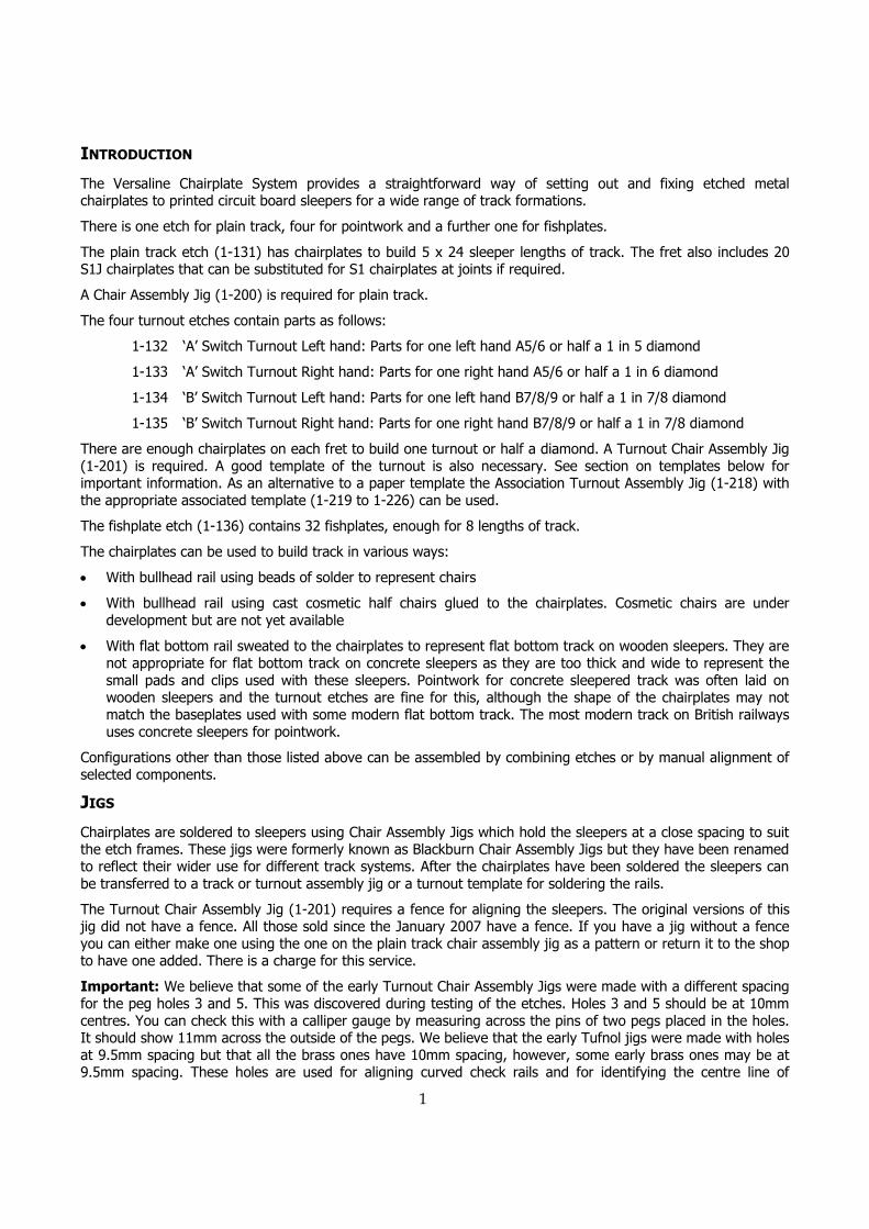
There are four closure rails and these are designated as straight or curved – two of each – and with a qualifying letter of s or c to indicate whether they are to be used on the straight or curved side of the turnout. Thus “Curved closure s”, abbreviated as “CvCl s” is the curved closure rail to be placed on the straight side of the turnout. See fig. 1 and also fig. 15 and Glossary on page 14.
Soldering
Solder paint is the quickest and easiest way to solder chairplates to the sleepers, but pre-tinning the chairplates also works well if you prefer that method.
3
Whichever method you use clean the chairplates thoroughly with a glass fibre scratch brush on both sides, always brushing in the direction away from the spine to avoid damaging or bending the chairplates.
If you are using cosmetic chairs or flat bottom rail the chairplates should always be tinned on the top surface whatever method you use to solder them to the sleepers. In these cases it is very important to get an even coating of solder on the chairplates as rail has to be sweated to them. If one chairplate at a joint, yet to be soldered, has an over-thick coating of solder the rail on the next joint may be held too high above the chairplate and the joint may fail to make. For these types of track we also recommend 188 solder as it forms less of a fillet at the joint.
Fig. 1: Labelling of strips on the etches
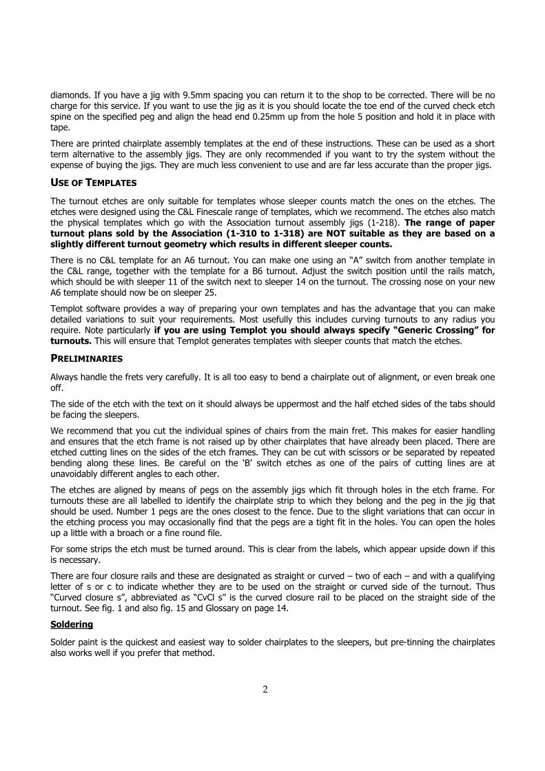
For tinning we suggest the following approach to get an even coating on each chairplate:
• Apply flux to the strip of chairplates.
• Place a small amount of solder on the iron and apply this to several chairplates at random. It will probably tin about four or five chairplates. The first chairplate for each load of solder will have a thick coat of solder and the last will be rather thin.
• Now gently rub the iron along the strip in each direction several times to spread the solder evenly. Use a very light touch so that you don’t bend any of the chairplates. You should now have an even coating of solder over maybe a dozen or more chairplates
• Repeat the solder and spread process until you get to the end of the strip.
• If the solder coating seems a bit too thick in some places put some flux on a scrap section of the spine and rub the iron on it to remove solder from the iron. Now apply the iron to the chairplates again to pick up some more solder from them and transfer this to the scrap until you have an even thin coating on the chairs.
If you use solder paint simply coat the bottom of each chairplate with the paint, being careful to keep it out of the half etches for the tabs. Then align the chairplates using the holes and pegs and press the soldering iron onto each chairplate in turn. It helps to bed down the chairplates if you press an old, small screwdriver onto each one before you remove the iron.
If you are pre-tinning the bottoms of the chairplates apply flux to each sleeper and then follow the same procedure.
Take care not to get solder into the half etched grooves in the tabs that hold the chairplates onto the spines. These are designed to provide a barrier that prevents the tab and the spine getting soldered to the sleepers. There should be just enough solder on each chairplate to hold it onto the sleeper. If solder oozes out when they are soldered to the sleepers you have too much and need to spread it over more chairplates next time or use less solder paint.

4
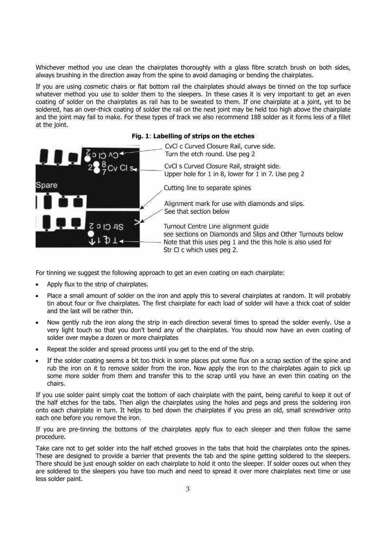
Fig. 2: Plain Track Etch
When you have applied the chairplates you can remove the spine by cutting the tabs with a round bladed knife. There should be a satisfying click as you cut through each one and the spine will lift off easily when they are all cut. The large block chairplates in the turnout etches have longitudinal tabs for additional strength. These can be cut off in the same way as the smaller tabs but they don’t always break off so easily so you may need to do a bit a fettling when you lift the sleepers from the jig. These tabs are necessary to prevent damage during handling.
PLAIN TRACK
Assembly
• Load 24 sleepers into the 1-120 Chair Assembly Jig. If you are using wide sleepers for the joints load only 22 plain sleepers.
• Apply solder paint or tin the chairplates.
• Lay the etch over the sleepers and locate it by the pins at each end of the jig.
• Solder the chairplates in place and cut off with a curved bladed knife.
• Repeat for the other rail.
Joints with Wide Sleepers
For track with wide sleepers at joints you should use the strip of S1J wide chairplates at one end of the fret. Use 2mm wide sleepers cut from Turnout Sleeper Strip.
• Gap the sleepers and load 10 into the 1-122 Turnout Chair Assembly Jig. The sleepers should be loaded at one end of the jig and aligned against the fence.
• Lay the etch for the S1J chairplates over the sleepers aligning the holes on peg 1 at each end of the jig.
• Solder the chairplates in place and cut off.
• Turn the sleepers round and place them at the other end of the jig so that the remaining 10 chairplates are aligned with the position for the second rail.
• Solder the chairplates in place and cut off.
Fishplates
• Cut fishplates from the etch using a knife on a hard surface; not a cutting mat as the fishplates will distort.
• Apply thin cyano adhesive to the web of the rail at the joint and place the fishplate with a pair of fine tweezers and press in place with a cocktail stick. Tricky at first but it is fairly easy to master the knack and they make a big difference to the appearance of the track.
5
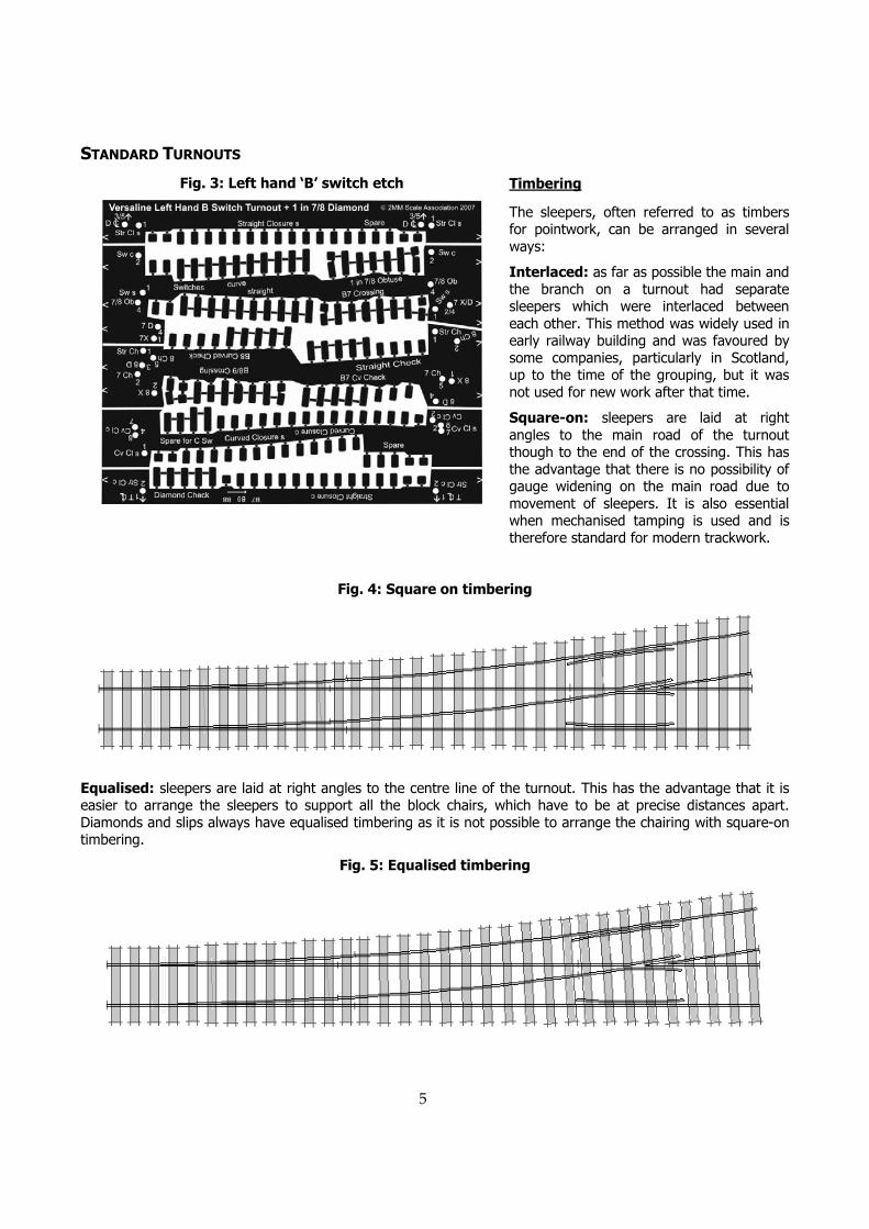
Fig. 3: Left hand ‘B’ switch etch
STANDARD TURNOUTS
Timbering
The sleepers, often referred to as timbers for pointwork, can be arranged in several ways:
Interlaced: as far as possible the main and the branch on a turnout had separate sleepers which were interlaced between each other. This method was widely used in early railway building and was favoured by some companies, particularly in Scotland, up to the time of the grouping, but it was not used for new work after that time.
Square-on: sleepers are laid at right angles to the main road of the turnout though to the end of the crossing. This has the advantage that there is no possibility of gauge widening on the main road due to movement of sleepers. It is also essential when mechanised tamping is used and is therefore standard for modern trackwork.
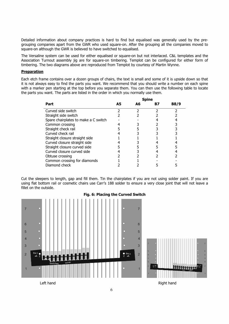
Fig. 4: Square on timbering
Equalised: sleepers are laid at right angles to the centre line of the turnout. This has the advantage that it is easier to arrange the sleepers to support all the block chairs, which have to be at precise distances apart. Diamonds and slips always have equalised timbering as it is not possible to arrange the chairing with square-on timbering.
Fig. 5: Equalised timbering
6
Detailed information about company practices is hard to find but equalised was generally used by the pre-grouping companies apart from the GWR who used square-on. After the grouping all the companies moved to square-on although the GWR is believed to have switched to equalised.
The Versaline system can be used for either equalised or square-on but not interlaced. C&L templates and the Association Turnout assembly jig are for square-on timbering. Templot can be configured for either form of timbering. The two diagrams above are reproduced from Templot by courtesy of Martin Wynne.
Preparation
Each etch frame contains over a dozen groups of chairs, the text is small and some of it is upside down so that it is not always easy to find the parts you want. We recommend that you should write a number on each spine with a marker pen starting at the top before you separate them. You can then use the following table to locate the parts you want. The parts are listed in the order in which you normally use them.
Spine Part A5 A6 B7 B8/9
Curved side switch 2 2 2 2 Straight side switch 2 2 2 2 Spare chairplates to make a C switch - - 4 4 Common crossing 4 3 2 3 Straight check rail 5 5 3 3 Curved check rail 4 3 3 3 Straight closure straight side 1 1 1 1 Curved closure straight side 4 3 4 4 Straight closure curved side 5 5 5 5 Curved closure curved side 4 3 4 4 Obtuse crossing 2 2 2 2 Common crossing for diamonds 1 1 - - Diamond check 2 2 5 5
Cut the sleepers to length, gap and fill them. Tin the chairplates if you are not using solder paint. If you are using flat bottom rail or cosmetic chairs use Carr’s 188 solder to ensure a very close joint that will not leave a fillet on the outside.
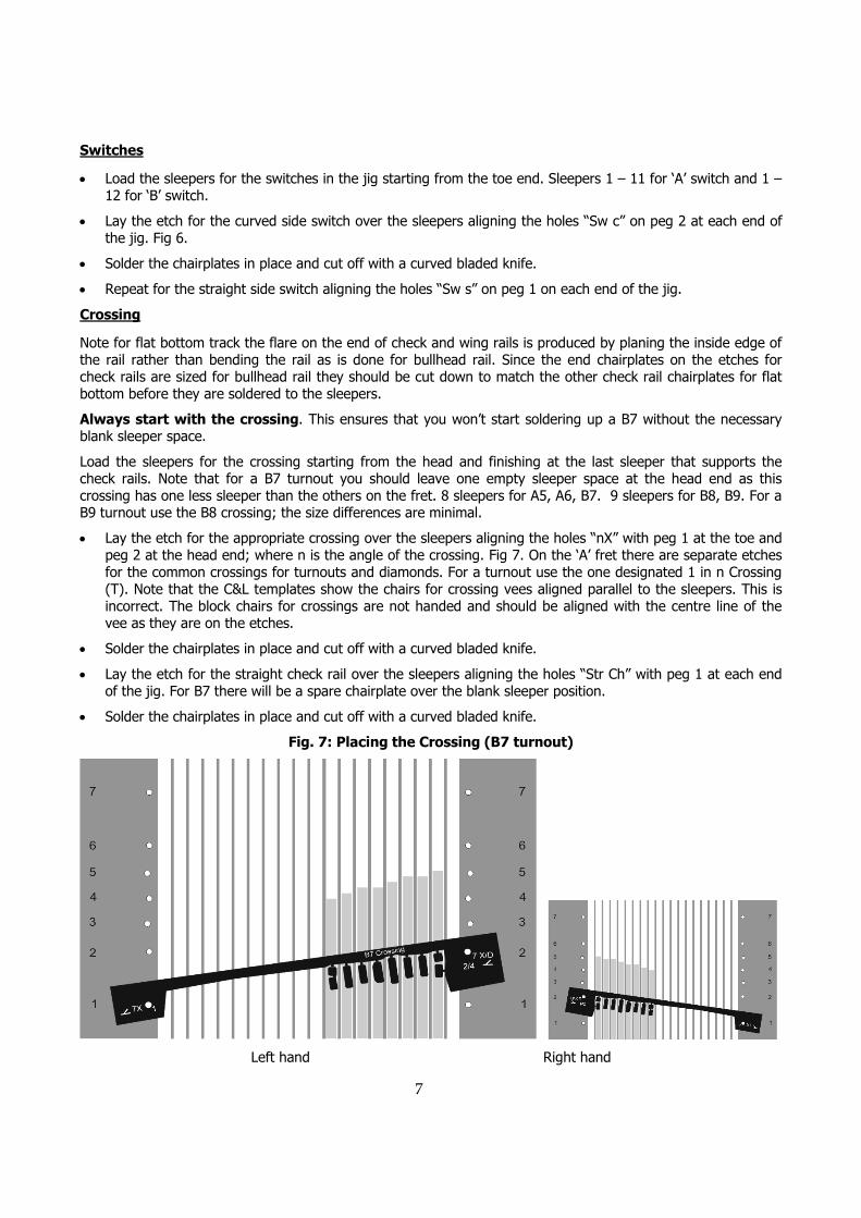
Fig. 6: Placing the Curved Switch
Left hand Right hand
7
Switches
• Load the sleepers for the switches in the jig starting from the toe end. Sleepers 1 – 11 for ‘A’ switch and 1 – 12 for ‘B’ switch.
• Lay the etch for the curved side switch over the sleepers aligning the holes “Sw c” on peg 2 at each end of the jig. Fig 6.
• Solder the chairplates in place and cut off with a curved bladed knife.
• Repeat for the straight side switch aligning the holes “Sw s” on peg 1 on each end of the jig.
Crossing
Note for flat bottom track the flare on the end of check and wing rails is produced by planing the inside edge of the rail rather than bending the rail as is done for bullhead rail. Since the end chairplates on the etches for check rails are sized for bullhead rail they should be cut down to match the other check rail chairplates for flat bottom before they are soldered to the sleepers.
Always start with the crossing. This ensures that you won’t start soldering up a B7 without the necessary blank sleeper space.
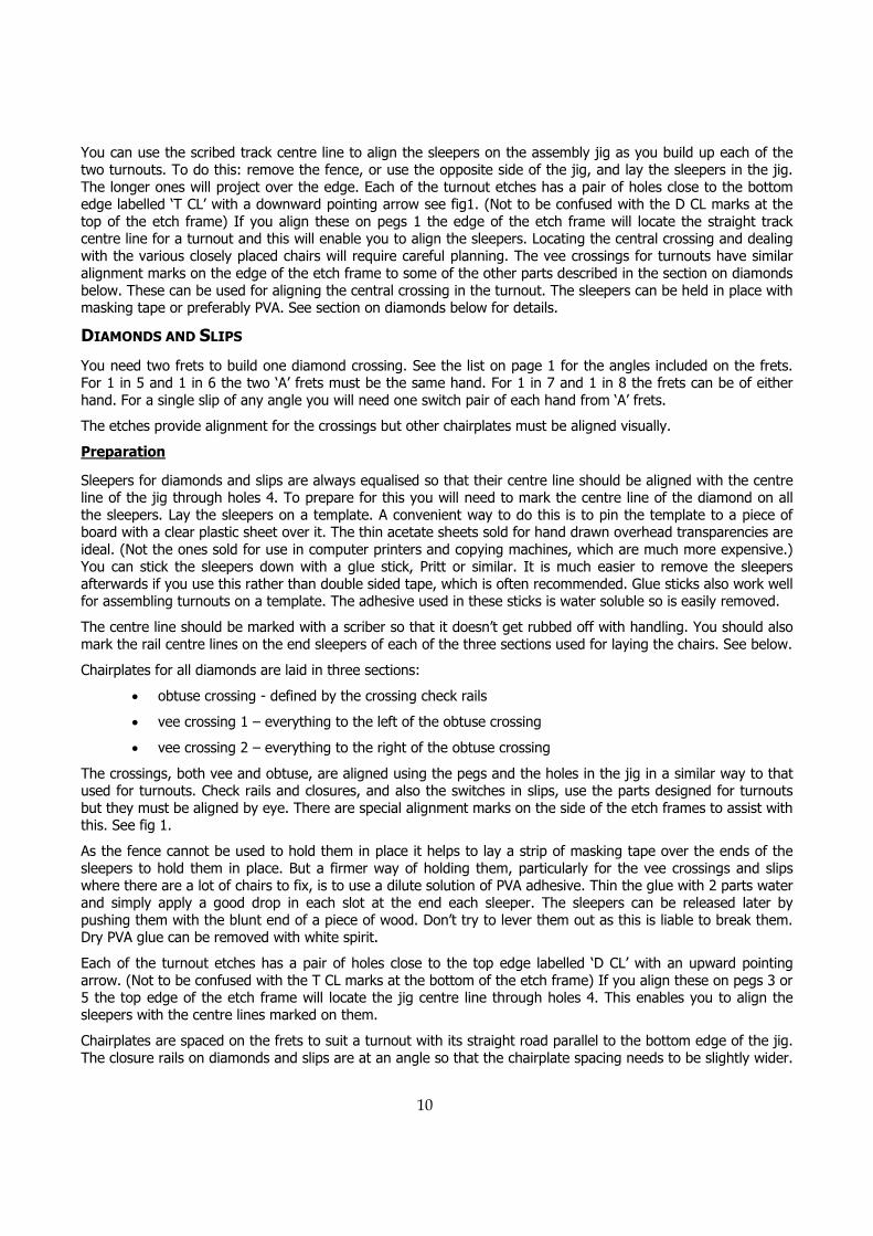
Load the sleepers for the crossing starting from the head and finishing at the last sleeper that supports the check rails. Note that for a B7 turnout you should leave one empty sleeper space at the head end as this crossing has one less sleeper than the others on the fret. 8 sleepers for A5, A6, B7. 9 sleepers for B8, B9. For a B9 turnout use the B8 crossing; the size differences are minimal.
• Lay the etch for the appropriate crossing over the sleepers aligning the holes “nX” with peg 1 at the toe and peg 2 at the head end; where n is the angle of the crossing. Fig 7. On the ‘A’ fret there are separate etches for the common crossings for turnouts and diamonds. For a turnout use the one designated 1 in n Crossing (T). Note that the C&L templates show the chairs for crossing vees aligned parallel to the sleepers. This is incorrect. The block chairs for crossings are not handed and should be aligned with the centre line of the vee as they are on the etches.
• Solder the chairplates in place and cut off with a curved bladed knife.
• Lay the etch for the straight check rail over the sleepers aligning the holes “Str Ch” with peg 1 at each end of the jig. For B7 there will be a spare chairplate over the blank sleeper position.
• Solder the chairplates in place and cut off with a curved bladed knife.
Fig. 7: Placing the Crossing (B7 turnout)
Left hand Right hand

8
• Lay the etch for the appropriate curved check rail over the sleepers aligning the holes “n Ch” with peg 2 at the toe end and peg 5 at the head end of the jig, fig 8.
• Solder the chairplates in place and cut off with a curved bladed knife.
Fig. 8: Placing the Curved Check Rail
Left hand Right hand
Closure Rails
Note: The order of assembly listed here is important. Some of the chairplates are very close together at the ends and previously soldered chairplates will interfere with the tabs of later chairplates if you don’t follow this sequence. Make sure that you have removed any traces of the tabs from the chairplates close to where you are about to solder new ones so that there is adequate clearance.
Fig. 9: Placing the Curved Closure Rails
Left hand Right hand

9
• Load the sleepers for the closure rails in the jig starting from the first sleeper after the switches and ending with the one before the check rails.
• Lay the etch for Straight Closure straight side over the sleepers aligning holes “Str Cl s” with peg 1 at each end of the jig.
• Solder and cut
• Lay the etch for Curved Closure straight side over the sleepers aligning the holes “Cv Cl s” with peg 1 at the toe end and peg 2 at the head end, fig. 9. There are different Curved Closure etches for A5 and A6 marked “5 Cv Cl s” and “6 Cv Cl s”. For B7 and B8 there is a single etch but there is a double hole at the head end. Use the appropriately marked hole. For a B9 turnout use the B8 closure rail holes.
• Solder and cut
• Repeat for Straight closure curve side by aligning holes “Str Cl c” with peg 2 at each end of the jig. Note that for ‘B’ switches on the sleeper nearest the crossing there needs to be an L1 chair on the straight closure rail as there is no room for an S1. The etch is arranged with an L1 chair correctly placed for a B8 turnout. For B7 and B9 this chair is on a different sleeper and must be aligned by eye. This is indicated on the etch alongside these chairs
• Solder and cut
• Repeat for Curved Closure curve side aligning holes “Cv Cl c” with peg 2 at the toe end and peg 4 at the head end.
• Solder and cut
OTHER TURNOUTS
‘C’ Switch Turnouts
Turnouts other than those specifically included in the etches can be built using the parts supplied. Additional chairplates are provided on the ‘B’ Switch fret for modifying the switch to make a ‘C’ switch. Do this as follows:
• Solder the chairplates for a ‘B’ switch as described above.
• Insert one additional sleeper between the original sleepers 5 and 6 and another between the original sleepers 10 and 11.
• Use the chairplates labelled “Spare for C Sw” on these sleepers, aligning them by eye.
• You can use any of the crossings supplied on the etches, but you will have to mark the rail centre lines on the sleepers from a template and align the curved closure rails by eye. You may need to find additional S1 chairplates from another etch.
Curved Turnouts
Curved turnouts in any of the configurations supplied on the etches can be built as follows:
• Design the layout using standard templates for straight turnouts, but cut narrow triangles out of the paper between sleepers – every four or five sleepers, depending how sharp your curve is – You can now gently curve the template to fit the layout.
• Solder the chairplates exactly as described above but apply the sleepers to your curved template and solder the rails there.
If you have Templot software you can use it to generate curved templates.
Tandem Turnouts
Treat the centre road as straight for soldering the chairplates even if it is curved. Lay the sleepers on the template and mark the track centre line of the centre road on each sleeper with a scriber.
10
You can use the scribed track centre line to align the sleepers on the assembly jig as you build up each of the two turnouts. To do this: remove the fence, or use the opposite side of the jig, and lay the sleepers in the jig. The longer ones will project over the edge. Each of the turnout etches has a pair of holes close to the bottom edge labelled ‘T CL’ with a downward pointing arrow see fig1. (Not to be confused with the D CL marks at the top of the etch frame) If you align these on pegs 1 the edge of the etch frame will locate the straight track centre line for a turnout and this will enable you to align the sleepers. Locating the central crossing and dealing with the various closely placed chairs will require careful planning. The vee crossings for turnouts have similar alignment marks on the edge of the etch frame to some of the other parts described in the section on diamonds below. These can be used for aligning the central crossing in the turnout. The sleepers can be held in place with masking tape or preferably PVA. See section on diamonds below for details.
DIAMONDS AND SLIPS
You need two frets to build one diamond crossing. See the list on page 1 for the angles included on the frets. For 1 in 5 and 1 in 6 the two ‘A’ frets must be the same hand. For 1 in 7 and 1 in 8 the frets can be of either hand. For a single slip of any angle you will need one switch pair of each hand from ‘A’ frets.
The etches provide alignment for the crossings but other chairplates must be aligned visually.
Preparation
Sleepers for diamonds and slips are always equalised so that their centre line should be aligned with the centre line of the jig through holes 4. To prepare for this you will need to mark the centre line of the diamond on all the sleepers. Lay the sleepers on a template. A convenient way to do this is to pin the template to a piece of board with a clear plastic sheet over it. The thin acetate sheets sold for hand drawn overhead transparencies are ideal. (Not the ones sold for use in computer printers and copying machines, which are much more expensive.) You can stick the sleepers down with a glue stick, Pritt or similar. It is much easier to remove the sleepers afterwards if you use this rather than double sided tape, which is often recommended. Glue sticks also work well for assembling turnouts on a template. The adhesive used in these sticks is water soluble so is easily removed.
The centre line should be marked with a scriber so that it doesn’t get rubbed off with handling. You should also mark the rail centre lines on the end sleepers of each of the three sections used for laying the chairs. See below.
Chairplates for all diamonds are laid in three sections:
• obtuse crossing - defined by the crossing check rails
• vee crossing 1 – everything to the left of the obtuse crossing
• vee crossing 2 – everything to the right of the obtuse crossing
The crossings, both vee and obtuse, are aligned using the pegs and the holes in the jig in a similar way to that used for turnouts. Check rails and closures, and also the switches in slips, use the parts designed for turnouts but they must be aligned by eye. There are special alignment marks on the side of the etch frames to assist with this. See fig 1.
As the fence cannot be used to hold them in place it helps to lay a strip of masking tape over the ends of the sleepers to hold them in place. But a firmer way of holding them, particularly for the vee crossings and slips where there are a lot of chairs to fix, is to use a dilute solution of PVA adhesive. Thin the glue with 2 parts water and simply apply a good drop in each slot at the end each sleeper. The sleepers can be released later by pushing them with the blunt end of a piece of wood. Don’t try to lever them out as this is liable to break them. Dry PVA glue can be removed with white spirit.
Each of the turnout etches has a pair of holes close to the top edge labelled ‘D CL’ with an upward pointing arrow. (Not to be confused with the T CL marks at the bottom of the etch frame) If you align these on pegs 3 or 5 the top edge of the etch frame will locate the jig centre line through holes 4. This enables you to align the sleepers with the centre lines marked on them.
Chairplates are spaced on the frets to suit a turnout with its straight road parallel to the bottom edge of the jig. The closure rails on diamonds and slips are at an angle so that the chairplate spacing needs to be slightly wider.

11
Because of this you will have to solder a small number of chairplates and then cut off and move the strip a short distance along the rail line. This is most noticeable with the sharpest angles.
Alignment
Only the crossing chairs can be aligned using the holes in the fret in a similar way to turnouts all the other rails must be aligned by eye. The etch frames have alignment marks for straight closure rails, switches and check rails along the left and right hand edges of the frame to help with this. These are of the form ‘<’ and ‘>’. Because there is so little room they are not identified with the chair strips to which they belong. The alignment marks should be aligned with the appropriate rail centre line. In practice one, or sometimes both edges, of the fret will be beyond the edge of the working area. The simple holder for the jig shown in figs 10 and 11 will help.
Fig.10: Holder for turnout chairplate soldering jig.
Material is 6mm ply or MDF. Ends should be a close fit to the jig. The two panel pins act as a stop. If you have ¼” material use a piece of 0.020” styrene under the jig to raise it to the level of the sides. Overall size approximately 60 x 140mm.
Fig. 11: The jig in its holder in use to solder the chairs for one end of a diamond.
Chairs for the vee crossing have been soldered in and the first check rail is in place for soldering. The side cheeks of both the jig and the holder are covered with masking tape and the centre line of one rail has been marked. The alignment marks on the etch frame have been enhanced to make them visible in the photo.
Placing the rail centre lines accurately is important. You should mark the centre lines on the end sleepers of each section from the template. However, these need to be checked before you lay the check and closure rails. After you have soldered the vee crossing check the spacing from the centres of the end chairs on the crossing to the draft rail centre line for the checks and closures. It should be 9.9mm measured at right angles to the rail line, not along a sleeper. (Gauge + 2 x ½ rail width)
12
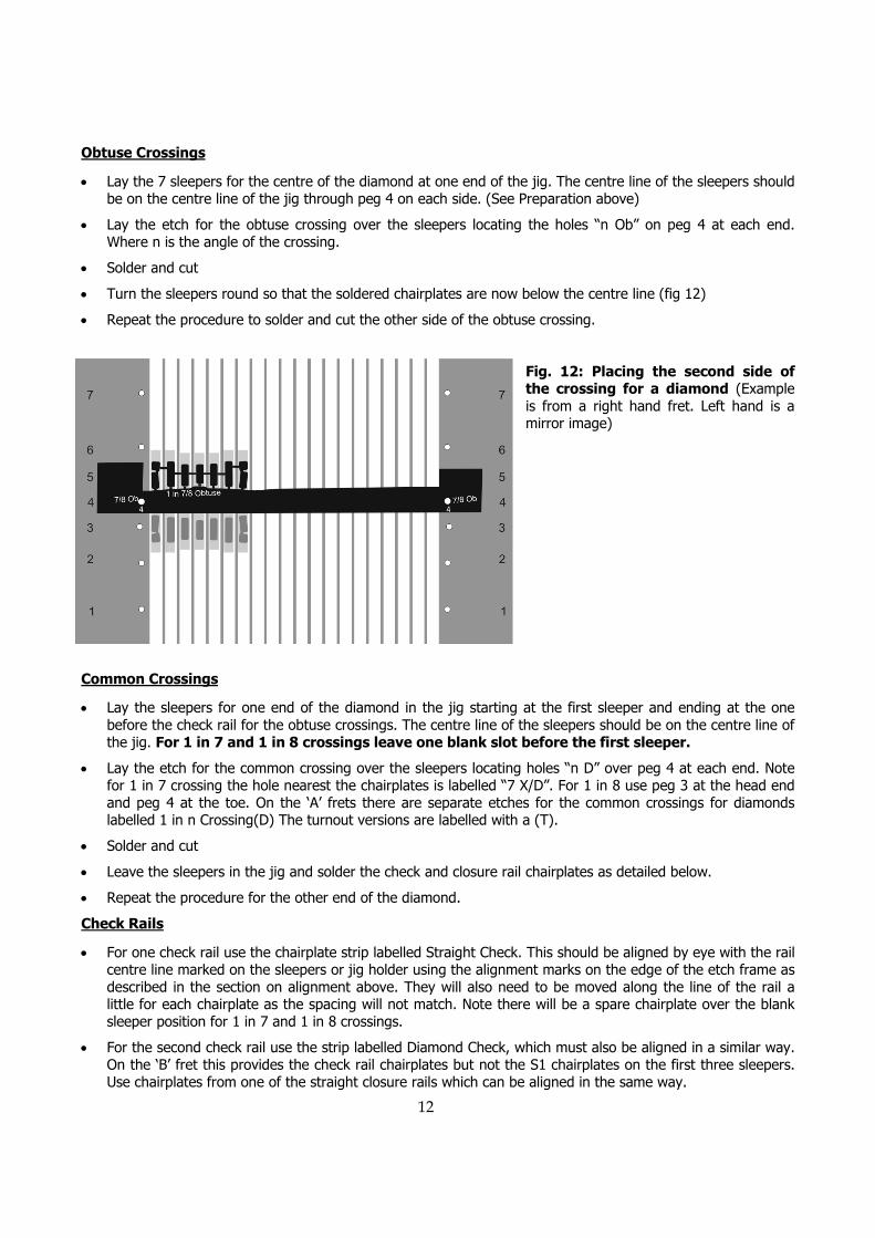
Obtuse Crossings
• Lay the 7 sleepers for the centre of the diamond at one end of the jig. The centre line of the sleepers should be on the centre line of the jig through peg 4 on each side. (See Preparation above)
• Lay the etch for the obtuse crossing over the sleepers locating the holes “n Ob” on peg 4 at each end. Where n is the angle of the crossing.
• Solder and cut
• Turn the sleepers round so that the soldered chairplates are now below the centre line (fig 12)
• Repeat the procedure to solder and cut the other side of the obtuse crossing.
Fig. 12: Placing the second side of the crossing for a diamond (Example is from a right hand fret. Left hand is a mirror image)
Common Crossings
• Lay the sleepers for one end of the diamond in the jig starting at the first sleeper and ending at the one before the check rail for the obtuse crossings. The centre line of the sleepers should be on the centre line of the jig. For 1 in 7 and 1 in 8 crossings leave one blank slot before the first sleeper.
• Lay the etch for the common crossing over the sleepers locating holes “n D” over peg 4 at each end. Note for 1 in 7 crossing the hole nearest the chairplates is labelled “7 X/D”. For 1 in 8 use peg 3 at the head end and peg 4 at the toe. On the ‘A’ frets there are separate etches for the common crossings for diamonds labelled 1 in n Crossing(D) The turnout versions are labelled with a (T).
• Solder and cut
• Leave the sleepers in the jig and solder the check and closure rail chairplates as detailed below.
• Repeat the procedure for the other end of the diamond.
Check Rails
• For one check rail use the chairplate strip labelled Straight Check. This should be aligned by eye with the rail centre line marked on the sleepers or jig holder using the alignment marks on the edge of the etch frame as described in the section on alignment above. They will also need to be moved along the line of the rail a little for each chairplate as the spacing will not match. Note there will be a spare chairplate over the blank sleeper position for 1 in 7 and 1 in 8 crossings.
• For the second check rail use the strip labelled Diamond Check, which must also be aligned in a similar way. On the ‘B’ fret this provides the check rail chairplates but not the S1 chairplates on the first three sleepers. Use chairplates from one of the straight closure rails which can be aligned in the same way.

13
Fig. 13: Placing the first check rail for a 1 in 7 diamond. Note the alignment marks on the etch frame lined up with the rail centre line extended across the jig sides. See also fig 11
Closure Rails
• Use the straight closure rail strips. These must be aligned with the rail centre line by eye as shown in fig 14. They will also need to be moved along the line of the rail a little for each chairplate as the spacing will not match. You may find it helpful to tape a straight edge to the jig along the edge of the fret frame so that you can slide the frame easily while maintaining the basic alignment. The straight closures are aligned with the top and bottom edge of the fret.
Fig. 14: Placing chairplates for a closure rail for a 1 in 7 diamond. Note the alignment marks on the etch frame lined up with the rail centre line extended beyond the jig side and also marked on the check rail chairs.
Slips
Slips follow the same basic procedure used for diamonds. Instead of straight closures you will need to use switches from an ‘A’ fret. The two S1 chairs at the toe end of these will not be required and you will probably have to leave off one or two chairs at the head end. Chairs for the slip roads must be individually laid (there aren’t very many). Use S1s, L1s or extend the obtuse crossing chairs as necessary. Clearances for the chairplates in the vicinity of the obtuse crossings are very tight, so you will probably need to adjust the chairing of the obtuse crossings. This should be planned in advance. The following table shows the closest spacing that is possible for different arrangements of individual chairs.
14
Adjacent chairs on a sleeper
2 S1 S1 + L1 2 L1
Rails close to parallel 2.4 2.0 1.6
Rails at 1 in 15 eg near a switch 2.5 2.1 1.7
Rails at 1 in 7 eg near a 1 in 7 crossing 2.6 2.2 1.8
Minimum clearances in mm for combinations of adjacent chairs on a sleeper
When the rails are closer than the figures for 2 L1 chairs a special chair should be used. When calculating the available space the special chairs on the obtuse crossing and the switch should be treated as S1s as they project the same distance beyond the rail.
GLOSSARY
The following terms are used in these instructions. All of them, apart from ‘Head’ and abbreviations used on the etches, are standard British railway terms:
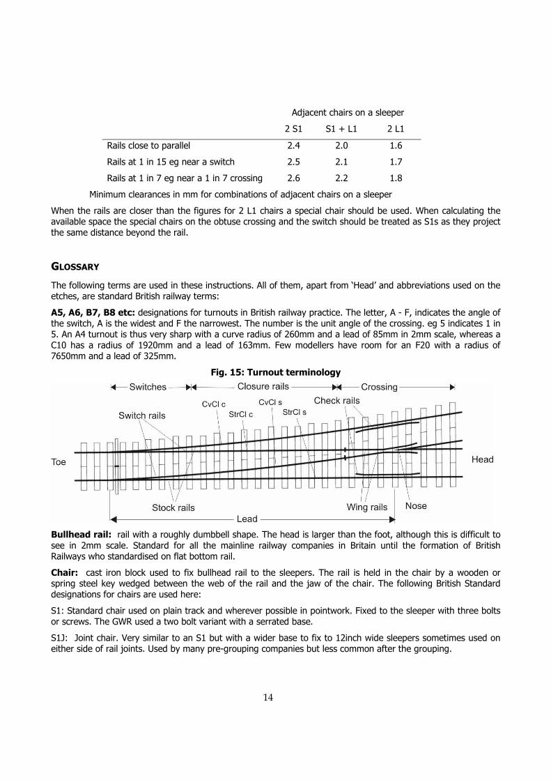
A5, A6, B7, B8 etc: designations for turnouts in British railway practice. The letter, A - F, indicates the angle of the switch, A is the widest and F the narrowest. The number is the unit angle of the crossing. eg 5 indicates 1 in 5. An A4 turnout is thus very sharp with a curve radius of 260mm and a lead of 85mm in 2mm scale, whereas a C10 has a radius of 1920mm and a lead of 163mm. Few modellers have room for an F20 with a radius of 7650mm and a lead of 325mm.
Fig. 15: Turnout terminology
Bullhead rail: rail with a roughly dumbbell shape. The head is larger than the foot, although this is difficult to see in 2mm scale. Standard for all the mainline railway companies in Britain until the formation of British Railways who standardised on flat bottom rail.
Chair: cast iron block used to fix bullhead rail to the sleepers. The rail is held in the chair by a wooden or spring steel key wedged between the web of the rail and the jaw of the chair. The following British Standard designations for chairs are used here:
S1: Standard chair used on plain track and wherever possible in pointwork. Fixed to the sleeper with three bolts or screws. The GWR used a two bolt variant with a serrated base.
S1J: Joint chair. Very similar to an S1 but with a wider base to fix to 12inch wide sleepers sometimes used on either side of rail joints. Used by many pre-grouping companies but less common after the grouping.

15
L1: Has a wide, square base. The overall area of the base is the same as an S1 but because it is shorter it can be placed closer to other chairs. Used in pointwork where two rails converge near to switches or crossings before they get too close when block chairs are used. a.k.a. bridge chair.
P: Slide Chairs that support the switches as they move. These chairs are bolted to the stock rails giving a distinctively different appearance from the normal keyed chairs on the outside of the rail.
Block Chair: Chairs to hold two or even three rails close together in pointwork where there is not room for separate chairs. For example in a ‘B’ switch there are 6 ‘P’ slide chairs to which the stock rail is bolted and 4 block chairs that hold both the stock rail and the switch rail as they diverge. There is also a large range of block chairs used for crossings and check rails.
Check Rail: rail inside the running rail that restrains the back of wheel flanges where there is a break in the opposite rail at a crossing. Also used on the inside rail of very sharp curves.
Closure rails: the rails connecting the switches to the crossing.
Common Crossing: acute angled crossing used in both turnouts and diamonds. a.k.a. vee crossing. The term frog, which is often used in model railway literature, is American terminology.
Crossing: the part where the left hand rail crosses the right hand one.
CvCl s, CvCl c: Abbreviations used on the etches to indicate curved closure rails straight side and curved side. See fig. 15.
Fishplate: short steel bar used, one each side of the rails, to join two rails. Usually with 4 bolts.
Flat bottom rail: rail with a flat base wider than the running surface. The standard for British railways since the 1950s. Supported on wooden sleepers by a steel or cast iron baseplate and on concrete sleepers by a much thinner steel or plastic pad. Fixed to the sleepers by spikes or various forms of patent clips.
Frog: see common crossing.
Head: the end of the turnout where the tracks diverge. (Not a standard term, but used in these instructions for clarity.)
L1 Chair: see chair.
Lead: the distance from the toe of the switches to the nose of the crossing.
Nose: the pointed tip of a crossing.
Obtuse Crossing: crossing used at the centre of diamonds. a.k.a. ‘K’ crossing.
Points: strictly the pointed tips of the switches, but often used as a synonym for turnout. Permanent way engineers usually talk of turnouts or point and crossing work. Signal engineers, who are primarily interested in the switches, which is what they have to control, use the term points and this has found its way into more general usage.
Sleeper: transverse component of track that supports and holds the rails to gauge. Originally always made of wood but now usually concrete or occasionally steel.
Stock Rail: the fixed rail in a switch. Often used in descriptions of model turnout building to include the closure rail up to the crossing as this is often made from a single piece of rail in model practice. In full size practice switches, closures and crossings are normally built as separate prefabricated units in an assembly yard and taken to the site for rapid re-assembly and installation when the engineers have a track possession.
StrCl s, StrCl c: abbreviations used on the etches to indicate straight closure rails straight side and curved side. See fig. 15.
Switch: the part of the turnout including the moving blade and the adjacent stock rail that direct the train to the appropriate route. A turnout always has a pair of switches.
S1 Chair: see chair.
16
Tandem Turnout: two turnouts superimposed on each other to save space. Often incorrectly known as three way turnout, which, strictly speaking, is superimposed turnouts with both sets of switches at the same point. These were briefly popular in the pre-grouping period but soon fell out of favour due to the problems created by the thickness of two switch toes at the same point. In a tandem turnout the switches are staggered.
Toe: the pointed tip of a switch. Generally used in these instructions to indicate that end of the turnout.
Vee crossing: see common crossing
Wing rail: the running rails at a crossing which are not part of the vee. They are bent to form a check rail alongside the vee. See fig. 15.
PAPER JIGS
The printed jigs on thw following page can be used for trialling the chairplates as a short term alternative to the brass chair assembly jigs (1-200 and 1-201). They are not recommended for long term use as they are much less convenient to use and it is also difficult to ensure that the chairplates are accurately positioned.
To use the paper jigs work as follows:
• Pin the paper to a piece of pin-board or soft wood.
• Lay a sheet of thin clear plastic over the jig. OHP write-on transparency film is ideal. (Available from stationers) If you don’t have anything suitable you can just apply the adhesive direct onto the paper jig, but you will need to replace it for each new set of sleepers, so make a few copies.
• Pin a strip of wood or card along the bottom edge of the jig to act as a fence. It should be thinner than the sleepers so that the frame of the fret can pass over it.
• Lay the sleepers on the jig fixing them down using a glue stick or with double sided tape. Double sided tape is quick to use but it is difficult to remove the sleepers and any remaining exposed areas can be a nuisance. If you are applying direct to paper the glue stick is an excellent way, provided you use a quality type. The economy versions have less sticking power and their high water content buckles the paper.
• Use two pins though the appropriate holes in the chairplate fret as described in the main instructions. If possible use large diameter map pins. The holes in the frets are 1mm diameter.
• Remaining adhesive from glue sticks can be removed with water. Double sided tape adhesive can be removed with white spirit.
N.B. The width of each jig when printed should be 76.3mm. Different printers may not reproduce these accurately to size so they have been produced here oversize to enable reduction on a photocopier. Variations of more than about 1mm will make it difficult to align the etches.

17
Paper Jig for plain track
Paper Jig for turnouts