vermilion energy inc. - fesaus · ♦ chemical injection and hydraulic or electrical control...
TRANSCRIPT

1
Vermilion Energy Inc.
Steady Growth
Stable Dividends
2 0 2 0 V I S I O N the best oil and gas company in the world
SPE Well Integrity Master Class
Completions Integrity
Nick Muecke
Well Construction Manager
Vermilion Oil & Gas Australia

2
SCOPE
♦ What is a completion?
♦ What is “completion integrity”?
♦ Design considerations
♦ Material selection
♦ Managing the well lifecycle.
♦ Applicable standards
♦ Impacts on completion integrity
♦ Example schematics
The term “fluid” is used through-out this presentation and
relates to gas, oil, water or chemical

3
What is a completion?
♦ A collection of discrete components that, when
combined, provide a conduit to:
bring produced fluids to surface or deliver injected
fluids to the reservoir in a controllable manner
provide reservoir data
provide isolation mechanisms for shut in (planned &
emergency), intervention, suspension and
abandonment
♦ Life of field and/or best economic fit
♦ Future Proofing
designed to cater for all phases of the well and
reservoir life (where feasible and cost effective)

4
Completion Integrity
What is completion integrity? ♦ The well fluids remain where they are supposed to be for the full well
life cycle (design, construction, production and abandonment)
How do we achieve it? ♦ The risk of loss of control of fluids (primarily hydrocarbons) during the
well life cycle is mitigated through a process of:
Design (material and component selection)
Installation management (procedures, fluids, chemicals,
equipment and barrier verification)
Maintenance, inspection and treatment (procedures, fluids,
chemicals, equipment and barrier verification)
Abandonment management (procedures, fluids, chemicals,
equipment and barrier verification)
Assessment and balance of risk
Individual and organisational competence

5
Common components
♦ Christmas trees, well heads, control, injection and cable termination blocks, surface or subsea …….
♦ Surface valves, chokes, actuators
♦ Chemical injection and hydraulic or electrical control systems (for surface and subsurface components)
♦ Tubing strings and connections and tubing hangers
♦ Surface and Sub Surface Safety Valves
♦ Mandrels (chemical, gas injection, gauge)
♦ Packers, liner hangers, seal bores
♦ Seal assemblies
♦ Control lines, chemical injection lines, joiners and terminators
♦ Clamps, centralisers, lock rings
♦ Sliding side door (mechanical or hydraulic)
♦ Flow control valves (mechanical or hydraulic)
♦ Artificial lift (gas, ESP, rod, jet, pcp, …)
♦ Nipples (isolation, gauge hang off, sleeving, contingency, …)
♦ Blast joints
♦ ……. It is a long list

6
Design Considerations
♦ Multiple or single zones, selective or not, comingled or not
♦ Multiple or single phase flow (slugging, layered, …)
♦ Well design considerations (casing design, trajectory, exposed formations, cementation, annular pressure, treatment regime, well kill, abandonment)
♦ Perforated, barefoot, screened, gravel packed, ….
♦ Sand production (well bore stress, well/treatment fluid compatibility, erosion)
♦ Flow rate (erosion management, wellhead loading, tubing stress, seal wear)
♦ Surface pressure (erosion & corrosion management, tubing stress)
♦ Reservoir fluid and pressure characteristics (corrosion management, pressure control, elastomer compatibility)
♦ Temperature (corrosion management, pressure control, tubing stress, elastomer selection, )
♦ Flow assurance (wax, asphaltines, scales)
♦ Sealing mechanisms (MTM, elastomeric)
♦ Fines migration (drawdown, well/treatment fluid compatibility, impairment)
♦ Intervention, servicing, life-cycle data gathering requirements
♦ Bull heading to frac, kill or chemical treatments (well bore stress regime, rock strength, formation characteristics, well pressure design envelope)
♦ Company and/or industry guidelines and Regulatory requirements (barriers – permanent, temporary)
♦ Inventory at hand, manufacturing lead times, standardisation ……
♦ The list is very long, complicated and usually requiring compromise …….

7
Material Selection
♦ Impacted by:
Fluid properties (H2S, CO2, water, salinity, chemicals)
Economics (price assumptions, field or well life)
Pressure (reservoir and partial pressure, stimulation)
Production rate and profile (when will water hit, souring)
Temperature (reservoir, overburden profile, ambient, stimulation)
Time (both equipment lead times and well life)
MTBF (reliability)
Ease of intervention (rig access or availability)
Facility design
Applicable standards (API, NACE, company, national, international)
Inventory at hand, supply lead times, standardisation (both yours’ and
your vendor’s)

8
Material Selection
♦ Compatibility with other materials
(dissimilar metals)
♦ Stagnant areas (seal areas, annuli,
gas lift mandrels, corrosion inhibition
methodology, …)
♦ Cement design (strength, annular
height, exposed formations, ….)
♦ Liner laps
♦ Movement due to pressure and temperature changes
♦ Packer setting locations (tubing & casing metallurgy,
cement, .…)
♦ Installation constraints (floating casing, T&D, rig type, …..)

9
Material Selection

10
Managing Integrity Through Lifecycle
Who is responsible?
What is the scope?
♦ Specification
♦ Design
♦ Installation
♦ Intervention and Maintenance
♦ Monitoring
♦ Scope changes (e.g. – access to different zones with different fluid
mixes, conversion from producer to injector, life extension)
♦ Abandonment
11
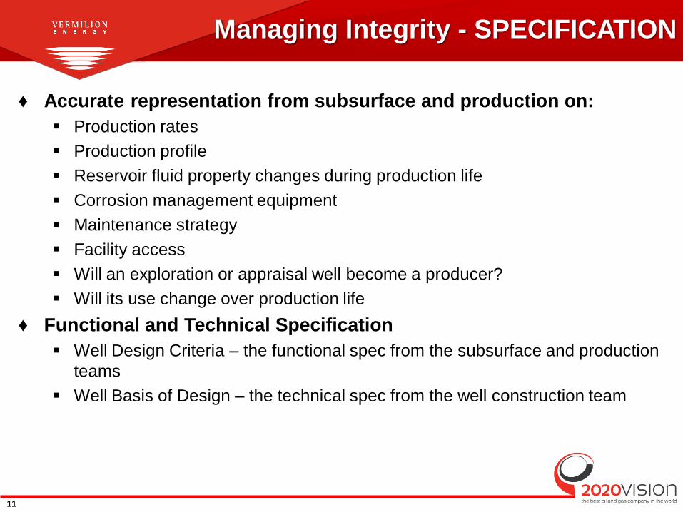
Managing Integrity - SPECIFICATION
♦ Accurate representation from subsurface and production on:
Production rates
Production profile
Reservoir fluid property changes during production life
Corrosion management equipment
Maintenance strategy
Facility access
Will an exploration or appraisal well become a producer?
Will its use change over production life
♦ Functional and Technical Specification
Well Design Criteria – the functional spec from the subsurface and production
teams
Well Basis of Design – the technical spec from the well construction team

12
♦ International Standards Organisation (ISO)
ISO 13533 Specification for Wellhead Equipment
ISO 11960 Specification for Casing and Tubing
ISO 15463 Field Inspection of New Casing, Tubing and Plain End Drill Pipe
ISO 10417 Design Installation, Repair and Operation of Sub Surface Safety Valves
ISO 10432 Specification for Subsurface Safety Valve Equipment
ISO 10426-1 Specification for Cements and Materials for Well Cementing
ISO 10426-2 Recommended Practice for Testing Well Cements
ISO 4406 Hydraulic fluid power - Fluids - Method for coding the level of contamination by solid particles
ISO 15156 Corrosion Resistant Alloys for Sulphide Service
♦ API (standards and recommended practices)
♦ NORSOK (Standard Norge)
♦ ANSI/NACE (largely obsolete – moving to ISO)
♦ Regulatory requirements or guidelines (state, national, international)
♦ Internal company standards
Standards, Regulations and Guidelines

13
Managing Integrity - DESIGN
♦ Fit for purpose and cost effective
♦ Design Safety Factors
♦ Future Proofing Can the well design accommodate changes in produced fluid (oil, gas, water)?
Can we cope with reservoir souring?
Changes in reservoir parameters (pressure, etc.)
Impact of future water production on sand production (change in erosion rates)?
Will the well need to be converted to gas/water injector later in field life? How?
Intervention capability:
• How do we intervene and stay within Barrier philosophy.
• How do we access downhole components? (slickline/e-line/CT/tractors etc.)
• How do we accommodate remedial repairs? (Insert Safety Valves, recover ESPs, stuck
plugs, fishing operations, sand clean out, scale)
• What do we give up with specific well designs? Be clear in BOD.

14
Managing Integrity - INSTALLATION
♦ Competency Supervisors
Work Teams
Well control (Different for horizontal vs Vertical)
♦ Barrier Verification Clear tracking of barriers installed at each phase.
Sign off to confirm correct barriers instated.
♦ Acceptance Criteria Identified “STOP” points in program (e.g. verification of casing integrity).
Requires sign-off by competent personnel to accept well status prior to proceeding.
Identifies remedial actions if criteria cannot be met.
♦ Management of Change (MOC) Controls deviation from existing program or standards
Defines changes in risk/cost/time/HSE exposure
Provides auditable tracking of operational decisions.
♦ Handover Pre-agreed well status for handover.
Verified by Well Construction and recipient (Operations) at time of handover.
Defines clearly how well is constructed and key components in design.
Serves as a manual for defining ongoing monitoring and maintenance of asset. • E.g. frequency of TRSV inflow tests, Xmas tree maintenance, functioning of downhole
components.

15
Managing Integrity - INTERVENTION
Same principal considerations as the installation process: ♦ Competency
♦ Barrier Verification and Acceptance Criteria
♦ Management of Change (MOC)
♦ Handover
In addition: ♦ For interventions, the well fluids (and pressure) are usually at surface and
often constrained by barriers that have to be removed (pack-offs, grease injection heads, etc).
♦ Maintenance and inspection prior to operations.
Is well maintenance effective – lack of maintenance can quickly impact on barriers complicating intervention operations.
Are the planned intervention barriers verifiable?
Do additional barriers need to be installed to enable operations to proceed?
♦ Handover from Production
♦ Intervention often requires Simultaneous Operations
Impact on Major Accident Events, ongoing facility operations, management systems

16
Managing Integrity - MONITORING
How do we ensure ongoing integrity?
♦ Regular testing programs – e.g. functioning and inflow testing of
SSSVs and pressure testing of Xmas Tree/wellhead valves and seal
systems.
♦ Regular maintenance – e.g. Xmas Tree/wellhead valve servicings
exercising SSSVs and flow control valves (Smart wells) and …
♦ Corrosion protection and monitoring, Erosion monitoring
♦ Well tracking sheets – regular reporting of all pressures and
corrosion and erosion coupons. Monitoring for variances.
♦ Annular fluid management
Annulus top ups
Dosing
Chemical injection
Problems may arise from formation water corroding from outside in
♦ Pressure monitoring
Annular pressure monitoring and management against MAASP
Annulus alarms

17
BARRIERS

18
Example Schematics – Platform Gas Well

19
Example Schematics – Platform ESP Oil Well

20
Example Schematics – Subsea Gas Well

21
Example Schematics – Subsea Oil Well

22
Example Schematics – Platform Multilateral Well

23
What is missing?