verifikation der intensitätsmodulierten strahlentherapie€¦ · · 2016-06-09verifikation der...
TRANSCRIPT

Verifikation der
Intensitätsmodulierten
Strahlentherapie
Dr. Lutz Müller, Director ICC IBA Dosimetry, Schwarzenbruck

© 2
00
6
Patient-specific Verification ?
3D Dose
Fields
3D Dose
In Patient
TPS
CT
Targ. Vol/Dose/constraints disturbed
Fields
Resulting
3D Dose
In Patient
Patient couch
Treatment unit Gantry =0°
X - ray beam
Patient couch
Treatmt unit
X - ray beam
3D Dose
In Phant

© 2
00
6
Generations of electronic IMRT Dosimetry
1st
Single fields,
perpendicular
2nd
Homo-
geneous
phantom,
composite 3rd
COMPASS

© 2
00
6
First Generation
The
First
Generation

© 2
00
6
I‘mRT MatriXX key features
Pixel Ion chamber technology
(air vented)
1020 (MXX) detectors in
24x24 cm matrix
Single detector F = 4.5 mm
(height 5mm), 0.07 cc
Parallel reading w/o dead time
Real time measurements
Software (OmniPro ImRT,
Accept)

© 2
00
6
Quasimodo Study – plan & MatriXX 1 x 1 mm
Plan
MatriXX
Gamma eval 3%/3mm

© 2
00
6
Example: error in jaw position
Plan measured difference
Profiles __plan __measured Y1 jaw displaced by 1.8 mm
1.8 mm

© 2
00
6
OmniProIMRT+

© 2
00
6
Compare plan and measurement

© 2
00
6
Measure Displacement and Rotation

© 2
00
6
Gamma Evaluation No grid adaptation needed

© 2
00
6
Verification Report

© 2
00
6
Second Generation
The
Second
Generation

© 2
00
6
MatriXX Evolution: MULTICube phantom
Multiple Configurations (6 cm increments)
Multiple depth positionning on the MatriXX
Optional film cassette

© 2
00
6
Workflow of Multicube Verification Phantom and Hybride Plan
Scan
Phantom
Irradiate
Phantom Plan to
Phantom

© 2
00
6
Pixel Chamber angular acceptance
Classical parallel plate
chamber
PIC ion chamber
extended electrodes, small gap
-> strongly anisotropic response
Diameter (4.5mm) and gap
(5mm) almost equal
-> nearly isotropic response
0° 90° 180°
signal
0°
90°
0°
90°
Irradiation of MatriXX from
ALL angles (0°- 360°) ?

© 2
00
6
MatriXX - Residual angular dependence

© 2
00
6
Angular Response of MatriXX Response correction with lookup table

© 2
00
6
Plan Verification in Multicube phantom

© 2
00
6
Varian RapidArc™ – RIGS, Copenhagen University, Denmark

© 2
00
6
Welcome to Nuremberg
21

© 2
00
6
Training in Hospitals Patients waiting, Emergency cases, Equipment in treatment room...

© 2
00
6
ICC Linac State-of-the-Art Equipment
• FFfree
• Vmat
• Cone-Beam CT
• 160 Leaf
collimator
• EPID
• Monte-Carlo TPS

© 2
00
6
CME Credit Recognition Oncology & Medical Physics
© 2
00
6
Relative Dosimetry Course W/ Mark DeWeese, Mid-South Radiation Physics

© 2
00
6
Albrecht Dürer 1525
26
Underweysung der Messung,
mit dem Zirckel und
Richtscheyt, in Linien, Ebenen
unnd gantzen corporen
durch Albrecht Dürer zů sammen getzogen /
vnd zů nutz allen kunstlieb habenden
mit zů gehörigen figuren / in
truck gebracht / im jar.
M. D. X X v.

© 2
00
6
Albrecht Dürer, wood engrave
Beamlets 2D plot 3D Anatomy

© 2
00
6
Is 2D QA really clinically relevant ?

© 2
00
6
Methodology
2 D
g
analysis
3 D
Clinical
analysis
Clinical
Parameters:
Max dose
Dose to 1cc sp. Cord
Mean dose
Dose to 95%

© 2
00
6
Requirement for QA Procedure
In presence of clinically relevant errors, the
QA procedure should result in ‚fail‘
This means to avoid 2 Situations:
QA procedure results in ‚pass‘ but error is
present (false negative)
QA procedure results in ‚fail‘ but error is not
present (false positive)

© 2
00
6
Correlation between 2D and clinical analysis
e.g. 95% min pass
rate for 3%/3mm
e.g. Max tollerable
dose to 1cc of
spinal cord

© 2
00
6
Mean Contralateral parotid Dose
4 %
Max. Acceptable
D95 error
False
positives
False
negatives

© 2
00
6
Error Range and Conclusion

© 2
00
6
Dose Reconstruction in Patient Anatomy
Salvador Dalí
Venus de Milo with
Drawers
Original plaster of 1936
with metal knobs on the
drawers and white fur tuft
covers

© 2
00
6
OCTAVIUS 4D
• 2D IC Array
• 729 ionization chambers
• chamber volume: 0.125cm³
• chamber distance : 10 mm
• active area: 27x27 cm²
• Sampling time: 200 ms
• Phantom rotates motor driven
simultaneous with the gantry
• Inclinometer
• no correction for gantry angle
dependent response needed
The PTW approach
Courtesy of B.Rhein, DKFZ

© 2
00
6
Measured depth dose curves
The equivalent field size for each segment or control point is calculated from detector signal
The depth dose for the equivalent field size is normalized to the detector dose for each segment (or control point)
All projected 3D doses per segment or control points are summed up
The PTW approach
3D dose projection inside the phantom
ICC Opening Schwarzenbruck 20.7.2012

© 2
00
6
COMPASS patents

© 2
00
6
Compass: from Entrance Fluence to 3D Patient Dose
MatriXX Detector Beam model
Dose engine
DICOM
plan
Real Fluence
CT

© 2
00
6
DIN 6875 /3 (Germany)
In case no dosimetric verification of the treatment
plan is performed, at least an independent MU-
calculation has to be performed for each field.
This can be done also using an independent,
validated, sufficiently accurate 3D dose alorithm,
which is independent from the original treatment
planning system.
New in COMPASS 3.0 -> direct comparison
measured- computed SHOWS INFLUENCE OF
DELIVERY DIRECTLY

© 2
00
6
Response –Prediction vs. Measurement
Predicted
response
for each
pixel
Measured
response
for each
pixel
Response
difference
for each
pixel
Histogra
m
of
response
differences

© 2
00
6
Dose measured
Target
OAR

© 2
00
6
DVH and beyond
© 2
00
6
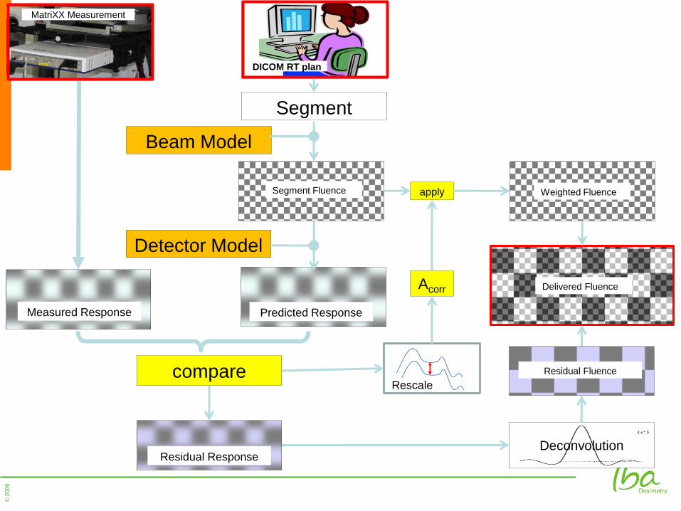
Segment
Beam Model
Detector Model
Acorr
Deconvolution
compare
DICOM RT plan
apply Segment Fluence Weighted Fluence
MatriXX Measurement
Measured Response Predicted Response
Residual Response
Residual Fluence
Rescale
Delivered Fluence

© 2
00
6
New in Compass 3.0
• Patient Data Base
• Simplified Detector Commissioning (1 field only)
• 2D Functionality (~OmniProIMRT/gantry holder)
• Better Commissioning
• Reconstructed/Calculated direct Comparison
• Multiple Measurements w/o Plan Reload
• Faster Algorithm (3-5 times)
• Upcoming COMPASS 3.1: Quick Check

© 2
00
6
COMPASS vs. Film
Gamma
3%/3mm

© 2
00
6
Correlation 2D/D
Film Compass2D Compass3D
D.J.L Wauben et al.
ESTRO 2010

© 2
00
6
A Customer Testimonial: Compass: The Hull Experience
Kevin Brownsword
Castle Hill Hospital, Hull, UK
ESTRO 2013
Geneva, Switzerland

© 2
00
6
Background to IMRT in Hull
Trained Dosimetrists
Step and Shoot (MSS) for Pancreas
• Film and Ion Chamber
Film to
MatriXX (IBA)
Estimated IMRT cases for 2013
Introduced VMAT for Prostates

© 2
00
6
Why Compass?
Familiar equipment
Accurate 3D dose algorithm for independent recalculations
2D measure of output
Indicate impact of 2D changes in 3D on patient CT
Possible add-ons in future

© 2
00
6
Clinical Plans
17 Clinical plans
Assessment protocol as with pre-clinical plans
2D Responses
Most within ±2%
Worst around ±5%
Compass to CC13 comparison
Linac TPS
(AAA)
Compass
(Meas.)
CL1 -1.2% -0.1%
CL2 -1.5% 1.0%
TB6 -0.8% 0.2%
Total -1.6% -0.2%
Mean deviation from point
dose measurement

© 2
00
6
Deviations in a Pelvic Delivery
51

© 2
00
6
2D QA Results

© 2
00
6
Single Segment
53

© 2
00
6
Symmetry....
54

© 2
00
6
And after LINAC Repair
55

© 2
00
6
Plan Iplan

© 2
00
6
Plan Eclipse

© 2
00
6
PBC Recon Dose (6% higher than TPS)

© 2
00
6
Monte Carlo Patient Plan

© 2
00
6

Vielen Dank !
…und nicht vergessen
WWW.ICC-IBADOSIMETRY.COM
Dr. Lutz Müller, IBA Dosimetry, Germany