verification of structural masonry design software...
TRANSCRIPT

Verification of
Structural Masonry Design
Software System
A Special Project Report
Presented to:
Dr. Russell Brown, Professor Steve Csernak, Dr. Bryant Nielson
Clemson University
In Partial Fulfillment
Of the Requirements for the Degree:
Master of Science
Civil Engineering
Prepared by:
Jonathan Cox
June 2010
Special Project Advisor: Dr. Russell Brown

ii

i
ABSTRACT
This special project that dealt with the verification of the NCMA Software covered a
wide variety of situations that were used to validate the accuracy and completeness of Version
5.0 of Structural Masonry Design Software developed for the National Concrete Masonry
Association and other sponsors. Through careful inspection, there were several key issues
corrected in the NCMA Software as well as the MathCAD files.
The MSJC 2008 and IBC 2009 codes were verified in this project for columns, walls
loaded out‐of‐plane, shear walls, and lintels. The NCMA Software and MathCAD files were also
updated for IBC 2000 ‐ IBC 2006 and MSJC 2002 ‐ MSJC 2005 to reflect errors and omissions in
previous versions of the software. Files were not only checked for reinforced structures, but
unreinforced as well. The verification of the NCMA Software using MathCAD yielded very
positive results, and when there was a discrepancy, the problem was investigated and rectified.
At the time of this report, some issues and verifications have yet to be performed which are
cited at the end of this report.
Most of the major corrections to the NCMA Software were in the Shear Wall module.
Significant modifications to the MathCAD files dealt with a 1.25 Mn modifier and seismic design
category/wall type for shear walls, ρmax and axial load limits for shear walls and out of plane
walls, flexural bending tensile stress updates for lintels, various corrections from old files and
changes in code interpretation, and modification of lintel reinforcement with regard to the 1.3
Mcr provisions and shear stirrups.
The majority of work for this project dealt with updating and correcting the MathCAD
files used for verification of the NCMA Software. For the most part, the NCMA Software has
been correct, except for statements that were inserted into the software outputs that explained
code provision changes or values and units that were incorrect.

ii
TABLE OF CONTENTS
ABSTRACT..................................................................................................................................................... i TABLE OF CONTENTS............................................................................................................................... ii LIST OF FIGURES AND TABLES............................................................................................................ iii 1.0 INTRODUCTION ................................................................................................................................... 4
1.1 Purpose ................................................................................................................................................ 4 1.2 NCMA Software.................................................................................................................................. 5
1.2.1 Software Capabilities ............................................................................................................................ 5 1.2.2 Software Limitations............................................................................................................................. 6 2.0 VERIFICATION ..................................................................................................................................... 7
2.1 Objective .............................................................................................................................................. 7 2.2 Philosophy............................................................................................................................................ 7 2.3 Scope .................................................................................................................................................... 8 2.4 Best Practices in Verification ............................................................................................................. 9 2.5 Methodology ........................................................................................................................................ 9
3.0 MSJC 2008 DESIGN CODE................................................................................................................. 11 3.1 Description ......................................................................................................................................... 11 3.2. Code Interpretation............................................................................................................................ 11 3.2.1 Strength Design ............................................................................................................................. 11 3.2.2 Allowable Stress Design ................................................................................................................ 13 4.0 IBC 2009 DESIGN CODE .................................................................................................................... 14
4.1 Description......................................................................................................................................... 14 4.2. Code Interpretation............................................................................................................................ 15 4.2.1 Strength Design ............................................................................................................................. 15 4.2.2 Allowable Stress Design ................................................................................................................ 15 5.0 Significant Changes/Corrections .......................................................................................................... 17
5.1 Description of Changes..................................................................................................................... 17 6.0 Column Design ...................................................................................................................................... 21
6.1 Description......................................................................................................................................... 21 6.2 Code Interpretation .......................................................................................................................... 22 6.3 NCMA Verification Files.................................................................................................................. 23
7.0 Shear Wall Design ................................................................................................................................. 24 7.1 Description......................................................................................................................................... 24 7.2 Code Interpretation .......................................................................................................................... 25 7.3 MathCAD Verification Files ............................................................................................................ 28
8.0 Out-Of-Plane Wall Design .................................................................................................................... 30 8.1 Description......................................................................................................................................... 30 8.2 Code Interpretation .......................................................................................................................... 30 8.3 MathCAD Verification Files ............................................................................................................ 34
9.0 Lintel Design.......................................................................................................................................... 35 9.1 Description......................................................................................................................................... 35 9.2 Code Interpretation .......................................................................................................................... 35 9.3 MathCAD Verification Files ............................................................................................................ 36
10.0 CONCLUSION .................................................................................................................................... 37 REFERENCES............................................................................................................................................ 38 APPENDIX A: COLUMN VERIFICATION FILES APPENDIX B: SHEAR WALL VERIFICATION FILES APPENDIX C: OUT OF PLANE VERIFICATION FILES APPENDIX D: LINTEL VERIFICATION FILES

iii
LIST OF FIGURES AND TABLES
Figure 2-6: Shear Wall Problem Bank
Figure 5.1: Comparison of Displays V5
Figure 5.2: Comparison of Displays V4
Figure 5.3: Shear Wall Display V5
Figure 5.4: Shear Wall Display V4
Figure 6-1: Column Load Data
Figure 6-2: Column Reinforcement Data
Figure 6-3: Column Construction Data
Figure 6-4: Column Design Data
Figure 7-1: Shear wall type drop down box.
Figure 7-2: Seismic Design Category drop down box.
Figure 7-3: V4 Shear Provisions
Figure 7-4: 1.5 Shear Increase
Figure 8-1: Axial Stress Limit
Figure 8-2: “Z” Values
Figure 8-3: “Z” Matrix
Figure 8-4: Moment Magnifier
Figure 8-5: Cracking Moment
Figure 9-1: fbt Table
Figure 9-2: 4/3 Limit on 1.3*MCR

4
1.0 INTRODUCTION
1.1 Purpose The National Concrete Masonry Society (NCMA) in conjunction with Drs. James K. Nelson and
Russell H. Brown have developed software for the design of masonry structures. The Phase II software
included design modules for the design of out-of-plane concrete masonry walls, in-plane concrete
masonry walls, and concrete masonry and reinforced concrete lintels using Allowable Stress or Strength
Design procedures and the requirements of the Masonry Standards Joint Committee (MSJC) and
International Building Code building codes (MSJC 1995, MSJC 1999, MSJC 2002, IBC 2000). The 3.0
version of this software was completed in December 2002. Its accuracy was verified by Bryan Thomas
Lechner and Johnny Lee McElreath in their Special Project Report, Verification of Masonry Design
Software Developed for the National Concrete Masonry Institute, Phase II.
Phase III of the software verification was performed and documented by Adam Hogan in his
thesis, Verification of Masonry Design Software National Concrete Masonry Institute, Phase III. The
Phase III version had the capability to design lintels and walls loaded either out-of-plane or in-plane,
along with the added capability to design columns, using Allowable Stress or Strength Design procedures.
The software was improved to include new design code requirements: IBC 2003 and MSJC 2005, to go
along with the MSJC 1995, MSJC 1999, IBC 2000, and MSJC 2002 codes present in the previous
version.
Phase IV of the software verification was performed by Clay Putnam and documented in his
special project report, Verification of Masonry Design Software National Concrete Mason Institute,
Phase IV. The Phase IV version had the capability to design lintels and walls loaded either out-of-plane or
in-plane, along with the added capability to design columns, using Allowable Stress or Strength Design
procedures. The software was improved to include new design code requirements: IBC 2006 to go along
with the MSJC 1995, MSJC 1999, MSJC 2002, and MSJC 2005 along with IBC 2000 and IBC 2003. As
well as introducing the use of the IBC Alternate Basic Load Combinations that allow the use of the 1/3
stress increase in the IBC.

5
This special project is a continuation of the work presented in the Phase I, Phase II, Phase III, and
Phase IV reports. However, the new Version 5.0 of the NCMA software includes the addition of MSJC
2008 and IBC 2009. The IBC 2009 code is equivalent to MSJC 2008 for the scope of MathCAD and
NCMA software with a few exceptions. The Existing MathCAD files were modified to reflect the
changes in the design codes to verify each of the design modules as well as new MathCADs being created
to verify partially grouted section properties. The completed results are displayed in the Microsoft Excel
spreadsheets in the Appendix for each module (columns, lintels, etc.) The verification completed in this
report yielded very accurate results and agreement between the two software programs.
1.2 NCMA Software The NCMA Design Software utilizes the trial-and-error method of design. This software is not
an analysis package, although it does have the capability to determine the critical design load combination
based on the support conditions, geometry, and user-defined loads acting on the masonry component
under consideration. The two options of inputting the critical section design forces, designated
“resistance side design”, or allowing the software to compute the critical section from the applied loads,
“load side design” are available. In order to perform a structural masonry design, all known values such
as the wall dimensions, masonry properties, steel properties, support conditions and applied loads (or
critical section design forces) are input and all unknown values, such as bar size, steel or grout spacing
and/or wall thickness are assumed. The NCMA Design Software also has the capability of developing
interaction diagrams based on the input wall properties and can plot the applied loads over this diagram.
This is a display option under the design data module or the user can elect to display design calculations.
The software will automatically return error messages when the loads are excessive or the design is
insufficient.
1.2.1 Software Capabilities The software has the capability to design masonry walls loaded either in-plane or out-of-plane,
both pre-cast concrete and masonry lintels, and masonry columns. Version 5.0 of NCMA Software

6
implemented the feature of selecting the seismic design category or shear wall type depending on what
code and module were being selected. The software can design fully grouted or partially grouted walls,
and the user has the option of choosing unreinforced or reinforced wall design. Allowable Stress or
Strength Design can also be selected under the design basis icon on the main toolbar.
Version 5.0 of the NCMA Software has now added two new codes. The code specific design
requirements and load combinations are now included for the following design codes:
1. MSJC 1995 Allowable Stress Design,
2. MSJC 1999 Allowable Stress Design,
3. IBC 2000 Allowable Stress and Strength Design,
4. MSJC 2002 Allowable Stress and Strength Design,
5. IBC 2003 Allowable Stress and Strength Design,
6. MSJC 2005 Allowable Stress and Strength Design,
7. IBC 2006 Allowable Stress and Strength Design,
8. MSJC 2008 Allowable Stress and Strength Design, and
9. IBC 2009 Allowable Stress and Strength Design.
Required development and splice lengths can be viewed and verified along with calculated service load
deflections for lintels and walls loaded out-of-plane.
1.2.2 Software Limitations Pilasters, out-of-plane walls that span horizontally, and beams (other than lintels) are beyond the
scope of the NCMA Software. Concentrated axial loads must be distributed over the length of the wall
according to the design code under consideration. Prestressed masonry walls cannot be designed.

7
2.0 VERIFICATION
2.1 Objective The purpose of this project is to verify the recent addition of MSJC 2008 and IBC 2009 to the
NCMA Software along with updating the software for corrections and revisions to older codes.
2.2 Philosophy MathCAD 2001 produced by Mathsoft, Inc. was used to independently check the NCMA Design
Software. A specific MathCAD verification program was developed for each design module and design
code (mainly in Phase I – Phase IV). The algorithms for each MathCAD file were derived independently
from those used in the NCMA Software using the design code under consideration and principles of
mechanics. The MathCAD files and their associated commentary are located in Appendices A through D.
The verification was conducted in two basic sections: the resistance side and the load side.
The resistance side of the software consists of the axial load, moment, and shear capacities
associated with the input wall properties and design code. The resistance side for a specific design
module was verified by iterating a wall design with respect to several isolated variables, such as bar size
or spacing. Values such as shear, moment, axial load, and their respective capacities were then compared
to the NCMA Software output. Percent errors around or above 0.2 – 0.3% were investigated. Large
discrepancies were usually caused by an isolated variable or round off and were easily corrected. This
process was continued until all necessary trials had been completed with negligible error.
The load side of the software consists of the critical section design forces generated from the
applied loads and the code dependent load combinations. The critical design section for reinforced
masonry walls loaded out-of-plane is located where the theoretical area of steel is the highest. In the case
of shear walls (loaded in-plane), columns and unreinforced masonry loaded out-of-plane, the critical
section occurs where the ratio of applied moment to moment capacity is highest for the axial load under
consideration (percent moment utilization). The critical design section for shear occurs when the ratio of
design shear-to-shear capacity, the percentage shear utilization, is the highest. The NCMA Software is

8
verified by comparing the design forces generated from the load combinations, critical section, and
associated load combination with MathCAD.
The verification can be broken down in this manner because the resistance side and load side
design modules are independent from one another. Changes in the load combinations or applied load
input will not affect how the section capacities are determined and vice versa.
2.3 Scope The scope of the verification includes Allowable Stress Design and Strength Design of columns
and lintels; reinforced and unreinforced out-of-plane design for both Allowable Stress Design and
Strength Design; and reinforced and unreinforced shear wall (in-plane) design for both Allowable Stress
Design and Strength Design. These modules are also checked when using the IBC 2000, 2003, and 2006
ASD Alternative basic load combinations. Sample verification tables for the future Version 5.0 software
are located in the Appendices.
This report does not include verification for design modules that remain unchanged from Phase
III including Allowable Stress Design for columns, lintels, out-of-plane walls, and shear walls based on
MSJC 1995 and 1999 design codes and Allowable Stress and Strength Design for columns, lintels, out-of-
plane walls, and shear walls for IBC 2000, MSJC 2002, IBC 2003 design codes.

9
2.4 Best Practices in Verification This project involved substantial verification of the NCMA Design Software. In order to facilitate proper
verification of the NCMA Design Software, certain problems were identified that tested specific
“triggers” in the software. These “triggers” were items that caused the software to select one logic process
over another, for instance, whether or not a shear wall was designated as a Special Shear Wall vs. a
Normal Shear Wall would trigger the 1.25Mn shear provisions in the 2008 MSJC Code. Many times, a
particular problem could be easily adapted to test multiple triggers with very minor changes to the
problem such as increasing/decreasing height, loads, and reinforcement.
2.5 Methodology While this verification process is extremely effective in testing the triggers that the NCMA Design
Software uses to design members, it is somewhat more difficult to explain than simply “brute force”
verification of the software. To counter this problem, a set of diagnostic problems was created and
designated as a future “problem bank”. This problem bank methodically documents the testing of each
individual trigger in the 2009 IBC and 2008 MSJC codes, prescribing what “trips” each of the triggers as
well as what conditions should change in order to enable/disable the trigger. An example of one of the
problem banks is included in this report as Figure 2-6: Shear Wall Problem Bank.

10
Code Used
Design Methodology Triggers Tested in File Loads Applied Modifications Made
IBC 2009 Strength Design Axial Load
(slenderness) 3.3.4.1.1
1829 K Axial Dead Increase Axial Load
by 1 Kip
IBC 2009 Strength Design Axial Load (ductility)
3.3.5.1 837.1 K Axial Dead
Increase Axial Load by 1 Kip
IBC 2009 Strength Design Axial Load (ductility)
3.3.5.1 524.3 K Axial Dead
Increase Axial Load by 1 Kip, Change wall type to
Intermediate
IBC 2009 Strength Design Axial Load (ductility)
3.3.5.1 417.1 K Axial Dead
Increase Axial Load by 1 Kip, Change wall
type to special
IBC 2009 Strength Design 2.5*Mn Shear limit
1.17.3.2.6.1.1 17850 K‐in, 30 K EQ
Increase Seismic Moment
IBC 2009 Strength Design 1.25 Mn Provisions
1.17.3.2.6.1.1 Alternate forces between bounds above and below
Alternate forces between bounds above and below
IBC 2009 Strength Design 1.25 Mn Provisions
1.17.3.2.6.1.1 35500 K‐In, 30 K EQ
Decrease Seismic Moment
IBC 2009 Allowable Stress
Design Axial Load (2.3.3.2) 168 K Axial Dead Increase Axial Load
by 1 Kip
IBC 2009 Allowable Stress
Design
Maximum Reinforcement Ratio
(2.3.3.4)
Special Shear Wall, At least 34.3 K of Axial
load, M/Vd > 1
Increase reinforcement
steel
IBC 2009 Allowable Stress
Design Shear Steel Required 18K Shear Increase Shear by 1
Kip
IBC 2009 Allowable Stress
Design Maximum Shear
Steel 19K Shear Increase shear to greater than 27K
IBC 2009 Allowable Stress
Design H/3 Limit on Steel
Spacing N/A
Increase Steel spacing greater
than 8'' Figure 2-6: Shear Wall Problem Bank

11
3.0 MSJC 2008 DESIGN CODE
3.1 Description
The 2008 edition of the Masonry Standards Joint Committee (MSJC) Building Code Requirements for
Masonry Structures (ACI 530/ASCE 5/TMS 402) and Specification for Masonry Structures (ACI
530.1/ASCE 6/TMS 602) was approved by the sponsoring societies (the American Concrete Institute
(ACI), the Structural Engineering Institute of the American Society of Civil Engineers (SEI/ASCE) and
The Masonry Society (TMS)) in the Fall of 2007.
3.2. Code Interpretation
3.2.1 Strength Design 3.2.1.1-1.25 Mn Provisions (1.17.3.2.6.1.1 MSJC 2008)
“When designing special reinforced masonry shear walls in accordance with Section 3.3 or A.3 or
Chapter 4, the design shear strength, φ Vn , shall exceed the shear corresponding to the development of
1.25 times the nominal flexural strength, Mn , of the element, except that the nominal shear strength, V
n ,
need not exceed 2.5 times required shear strength, Vu .”
This is a significant change from previous versions of the MSJC code; previous versions also contained
the 1.25 Mn provisions as well as the 2.5 upper limits on the required strength, however, previous versions
applied to “masonry members” instead of only special shear walls. In previous versions of the software
these provisions were included only in shear wall design. However, these provisions should have been
included in lintel design, column design and out-of-plane wall design for walls designed to IBC 2006 and
earlier codes [masonry members]. This has been corrected in version 5.0 of the NCMA software.
3.2.1.2-Factored Axial Stress (3.3.5.3 MSJC 2008)

12
“Walls with factored axial stress of 0.20 f’m or less – The procedures set forth in this section shall be used
when the factored axial load stress at the location of maximum moment satisfies the required computed
by Eq. (3-24).
Pu/Ag < 0.20 f’m (3-24)
When the slenderness ratio, h/t, exceeds 30, the factored axial stress shall not exceed 0.05f’m.
This provision was implemented in MSJC 2005 and was subsequently added to NCMA Software. The
upper limits on axial load for a large slenderness ratio however, were added and verified in version V of
the NCMA software.
3.2.1.3- Moment Magnifier (3.2.2.4.1 - 3.2.2.4.4 MSJC 2008)
3.2.2.4.1 – Members shall be designed for the factored axial load, Pu, and the moment magnified for the
effects of member curvature, Mc.
3.2.2.4.2 – The magnified moment, Mc, shall be determined either by a second-order analysis, or by a
first-order analysis and Eqs. (3-13) and (3-14).
(3-13)
(3-14)
3.2.2.4.3 - It shall be permitted to take δ = 1 for members in which h/r ≤ 45
3.2.2.4.4 - It shall be permitted to take δ = 1 for members in which 45 ≤ h/r ≤ 60, provided the nominal
strength defined in section 3.2.2.2 is reduced by 10 percent.
This is a new code provision that adds a moment magnifier to the design moment for unreinforced, out-
of-plane masonry walls designed by Strength Design methodology. This provision was implemented at
for each load case considered by the software, as well as each of the hundreds of design sections
calculated by the software, as Pu varies due to self-weight of the wall.

13
3.2.2 Allowable Stress Design 3.2.2.1 - 1.5 V Multiplier (1.17.3.2.6.1.2 MSJC 2008)
“When designing special reinforced masonry shear walls in accordance with section 2.3, the shear or
diagonal tension stress resulting from in-plane seismic forces shall be increased by a factor of 1.5. The
1.5 multiplier need not be applied to the overturning moment.”
This prevision was implemented in the 2008 MSJC and 2009 IBC codes anytime a reinforced shear wall
was designed as a special shear wall subject to seismic forces. The NCMA software handles this
provision by increasing the design shear by 50% anytime a seismic shear is present.
3.2.2.2 – Allowable Flexural Tensile Stress (1.13.3.2 MSJC 2008)
“For masonry designed in accordance with Chapter 2, the cracking moment, Mcr, shall be computed
using the allowable flexural tensile stress taken from Table 2.2.3.2 multiplied by a factor of 2.5. For
masonry designed in accordance with Chapter 3, the cracking moment, Mcr, shall be computed using the
value for the modulus of rupture, fr, taken from Table 3.1.8.2.”
The NCMA software handles this change exactly as it is described, by taking the values from Table
2.2.3.2 and increasing them by a 2.5 multiplier.
3.2.2.3 – Rho – Max provisions (2.3.3.4 MSJC 2008)
“Special reinforced masonry shear walls having a shear span ratio, M/Vd, equal to or greater than 1.0
and having an axial load, P, greater than 0.05f’mAn, which are subject to in-plane forces, shall have a
maximum ratio of flexural tensile reinforcement, ρMax, not greater than that computed as follows:
⎟⎟⎠
⎞⎜⎜⎝
⎛+
=
m
yy
m
ff
nf
nf
'2
'maxρ (2-22)
The maximum reinforcement ratio does not apply in the out-of-plane direction.”

14
This provision was in the 2006 IBC and was adopted by the 2008 MSJC during this code cycle. It applies
to special shear walls designed with Allowable Stress Design under the 2006 IBC, 2008 MSJC and 2009
IBC. This provision will be derived in later sections of this report.
3.3 MathCAD Verification Files
MathCAD files for verification of the 2008 MSJC requirements were created from previous
MathCAD files created by Clay Putnam, Eric Burgess, Oliver Himbert, Bryan Lechner, Johnny
McElreath, and Adam Hogan. The newly updated files for 2008 MSJC were created from MSJC 2005
files because the load combinations and design procedures are very similar. The one-third stress increase
is present in all 2008 MSJC MathCAD’s subject to its provisions. The specific modifications to these
files will be listed in later sections as part of each design module.
4.0 IBC 2009 DESIGN CODE
4.1 Description The 2009 edition of the International Building Code (IBC) was approved by the International
Code Counsel and is incorporated into the NCMA Software. The IBC 2009 Design Code adopts the
MSJC 2008 Design Code for “load side” and “resistance side” design with a few changes. The main
difference is that IBC 2009 does not use the one-third stress increase in Allowable Stress Design (unless
Alternate Basic Load cases are selected), while MSJC 2008 does. Other changes have little effect on the
design and results generated by the NCMA Software and MathCAD files and will be mentioned later.

15
4.2. Code Interpretation
4.2.1 Strength Design The strength design of masonry structures in the 2009 IBC code (Section 2108) refers to the requirements
of Chapters 1 and 3 of the 2008 MSJC code, with the exception of several modifications. These include
sections pertaining to welded and mechanical splices (Section 2108.3) and AAC Masonry (Section
2108.1). Since these requirements are not included in the new NCMA Software, they are not discussed
any further and were not part of the verification process. The following modifications are incorporated
into the NCMA Software:
1. The required development length of reinforcement shall be determined using MSJC Equation
3-16, but shall not be less than 12 inches nor greater than 72 bar diameters.
2. Minimum lap splice length for bars in tension or compression shall be 0.002dbFs where db is
the bar diameter and Fs is the allowable stress in the reinforcement. This computed lap splice
length shall not be less than 12 inches and in no case shall the splice length be less than 40
bar diameters. Where the design tensile stresses in the reinforcement exceed 80 percent of
the allowable tensile stress, the lap splice length shall be increased not less than 50 percent of
the minimum required length (Section 2107.5).
This provision was incorporated into Version IV of the NCMA software and verified by Clay Putnam. It
was also verified during this verification cycle.
All other design issues and equations such as minimum nominal thicknesses, maximum permitted axial
load, modulus of rupture values, and etc. remained the same between MSJC 2008 and 2009 IBC.
4.2.2 Allowable Stress Design The allowable stress design of masonry structures in the 2009 IBC code (Section 2107) refers to the
requirements of Chapters 1 and 2 of the 2008 MSJC code, with the exception of several modifications.

16
These include sections pertaining to welded and mechanical splices (Section 2107.4). Since these are not
included in the NCMA Software, they are not discussed any further or considered in verification. The
following modifications are incorporated into the NCMA Software:
1. Minimum lap splice length for bars in tension or compression shall be 0.002dbFs , where db is the
bar diameter and Fs is the allowable stress in the reinforcement. This computed lap splice length
shall not be less than 12 inches and in no case shall the splice length be less than 40 bar
diameters. Where the design tensile stresses in the reinforcement exceed 80 percent of the
allowable tensile stress, the lap splice length shall be increased not less than 50 percent of the
minimum required length (Section 2107.3).
2. The bar diameter shall not exceed one-eighth of the nominal wall thickness and shall not exceed
one-quarter of the least dimension of the cell, course, or collar joint in which it is placed (Section
2107.5).
3. Section 2107.2 is the provision in 2009 IBC that deletes the existing load combinations in Section
2.1.2.1 of MSJC 2008.
4.3 MathCAD Verification Files
MathCAD files for verification of the 2008 MSJC requirements were created from previous
MathCAD files created by Clay Putnam, Eric Burgess, Oliver Himbert, Bryan Lechner, Johnny
McElreath, and Adam Hogan. The newly updated files for 2009 IBC were created from IBC 2006 files
because the load combinations and design procedures are very similar. The one-third stress increase is
present only in 2009 IBC MathCAD’s subject to its provisions (MathCADs that use Alternate Basic Load
combinations). The specific modifications to these files will be listed in later sections as part of each
design module.

17
5.0 Significant Changes/Corrections
5.1 Description of Changes Version 5.0 of the NCMA software has incurred many changes and improvements from its
predecessor’s, and not all of these changes are limited to updating code provisions. This section of the
report is dedicated to changes that are not code based in nature. The changes range from improvements to
the interface, to improvements in output messages, to how the software handles certain circumstances.
These changes are listed below, broken down by design module for convenience:
i) General Changes to the NCMA Software
(1) Removed grid lines on output
(2) Changed default code to 2009 IBC ASD
(3) Changed default wall height to 24’’ from 0’’
(4) Improved display of input loads by graying out inappropriate data
ii) Changes to Columns
(1) Corrected units display
iii) Changes to Lintels
(1) Corrected spacing errors from previous versions where a lintel that did not require shear
stirrups would display a required spacing of 0.0000e10.
(2) Added display of Ig and fr to calculations page
(3) Improved output verbiage
(4) Updated help files
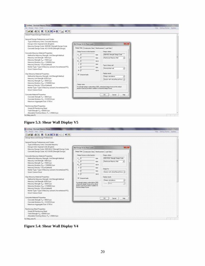
iv) Changes to Shear Walls
(1) Rearranged Design Data tab
(2) Added SDC vs. Shear wall type drop down menu for appropriate building codes
(3) Added the display of the slenderness reduction factor
(4) Added the display of the axial load vs. slenderness limit
(5) Added the display of D + .75L + .525Q load combination to Axial load check
18
(6) Improved output verbiage
(7) Updated help files
v) Changes to Out-of-Plane Walls
(1) Improved Interaction diagram
(2) Improved output verbiage
(3) Updated help files
(4) Added display of axial load vs. slenderness limit.
(5) Added the display of D + .75L + .525Q load combination to Axial load check
First, many of the general changes can be seen in Figure 5.1: Comparison of Displays V5 and Figure
5.2: Comparison of Displays V4. Second, the changes to the shear wall module had a significant code
impact as well, since a new user input, Shear wall type or Seismic design Category, was required. These
changes can be seen in Figure 5.3: Shear Wall Display V5 and Figure 5.4: Shear Wall Display V4.
These changes were used to trigger the 1.25Mn provisions as well as several other code provisions. As the
provision that drove this development was previously dependent on SDC instead of Shear wall type, the
drop down tab will change to a Seismic design category if the code being used is IBC 2006-IBC 2000.

19
Figure 5.1: Comparison of Displays V5
Figure 5.2: Comparison of Displays V4
20
Figure 5.3: Shear Wall Display V5
Figure 5.4: Shear Wall Display V4

21
6.0 Column Design
6.1 Description The Column design process in the NCMA Software has not changed from the previous versions of the
software. The description of Column design can be found in Verification of the National Concrete
Masonry Association Masonry Design Software Phase III by Adam Hogan. The process of verification
for columns is that the user specifies the loads, wall height, thickness, reinforcing bar size, and layout in
the “edit data” module. The user must also specify whether or not to use the 1/3 stress increase; However,
the software will not accept a design under the IBC code using the 1/3 stress increase unless Alternate
Basic load combinations are selected. These inputs are illustrated below in the NCMA Software “edit
data” module:
Figure 6-1: Column Load Data Figure 6-2: Column Reinforcement Data

22
Figure 6-3: Column Construction Data Figure 6-4: Column Design Data
6.2 Code Interpretation 3.2.1.1-1.25 Mn Provisions (1.17.3.2.6.1.1 MSJC 2008)
“When designing special reinforced masonry shear walls in accordance with Section 3.3 or A.3 or
Chapter 4, the design shear strength, φ Vn , shall exceed the shear corresponding to the development of
1.25 times the nominal flexural strength, Mn , of the element, except that the nominal shear strength, V
n ,
need not exceed 2.5 times required shear strength, Vu .”
This is a significant change from previous versions of the MSJC code; previous versions applied to
“masonry members” instead of only special reinforced shear walls. In previous versions of the software
these provisions were included only in shear wall design when they should have also included Out-of-
plane walls and Columns. A statement regarding this lack of consideration was added to these modules,
the statement reads “Provisions of 3.1.3 are not considered in shear calculations”. It should be noted that
these provisions do not apply to columns designed under MSJC 2008 or IBC 2009.

23
6.3 NCMA Verification Files There was a change from standard verification practices for column verification. Instead of using
MathCAD sheets to verify the accuracy of the NCMA software, it was possible to verify the software’s
solution with the previous version of the software.
Verifications of the axial load, moment and shear capacities were completed, for each strength
design code, by performing various problems in the NCMA software and comparing them to problems
with the same parameters executed in the previous version of the NCMA software. Comparisons were
completed for all available CMU and clay masonry widths. Each problem that was executed varied by
changing one or many of the following parameters: loading patterns, reinforcement sizes, reinforcement
arrangements, reinforcement spacing, column width and depth, and column height. Once the problems
were performed in NCMA, values for the factored axial load, factored moment, factored shear, moment
capacity, shear capacity, shear force in steel, and the value of maximum allowable axial load were
compared. Microsoft Excel spreadsheets have been created to verify output of several varying examples
between MathCAD and the NCMA Software. These sheets, along with examples from the two software
packages, are included in this report as appendix A.

24
7.0 Shear Wall Design
7.1 Description The shear wall design process in the NCMA Software has not changed significantly from the previous
versions of the software. The description of shear wall design can be found in Verification of the
National Concrete Masonry Association Masonry Design Software Phase II by Johnny McElreath and
Bryan Lechner. The process of verification for shear walls is similar to columns in that the user specifies
the loads, wall height, thickness, and length (in case of shear walls), reinforcing bar size, and layout in
the “edit data” module. However, a completely new user‐selected feature has been added, the ability to
select the Seismic Design Category or Shear wall type depending on which building code is used. This is
illustrated below in the NCMA Software “edit data” module:
Figure 7-1: Shear wall type drop down box. Figure 7-2: Seismic Design Category drop down box.

25
7.2 Code Interpretation 7.2.1-1.25 Mn Provisions (1.17.3.2.6.1.1 MSJC 2008)
“When designing special reinforced masonry shear walls in accordance with Section 3.3 or A.3 or
Chapter 4, the design shear strength, φ Vn , shall exceed the shear corresponding to the development of
1.25 times the nominal flexural strength, Mn , of the element, except that the nominal shear strength, V
n ,
need not exceed 2.5 times required shear strength, Vu .”
This is a significant change from previous versions of the MSJC code; previous versions only multiplied
the design shear by a factor of 1.25 and created a second table of reinforcing steel required but did not
enforce the 2.5 limit on the provisions. This is illustrated below in Figure 7-3: V4 Shear Provisions.
Figure 7-3: V4 Shear Provisions
The 2.5 cap on the design shear has been corrected in version 5.0 of the NCMA software. The scaling
factor was derived by using the total moment demand, Mu, and dividing by 1.25 multiplied by the total
moment capacity, Mn, divided by the appropriate phi factor.

26
The software would run the shear design once with the design shear force determined from load
combinations and then run it again with the design shear force multiplied by the scaling factor. If this
shear resulted in a shear larger than 2.5 multiplied by the original design shear, the software will use the
original design shear.
7.2.2 – Rho – Max provisions (2.3.3.4 MSJC 2008)
“Special reinforced masonry shear walls having a shear span ratio, M/Vd, equal to or greater than 1.0
and having an axial load, P, greater than 0.05f’mAn, which are subject to in-plane forces, shall have a
maximum ratio of flexural tensile reinforcement, ρMax, not greater than that computed as follows:
⎟⎟⎠
⎞⎜⎜⎝
⎛+
=
m
yy
m
ff
nf
nf
'2
'maxρ (2-22)
The maximum reinforcement ratio does not apply in the out-of-plane direction.”
This provision was in the 2006 IBC and was adopted by the 2008 MSJC during this code cycle. It applies
to special shear walls designed with Allowable Stress Design under the 2006 IBC, 2008 MSJC and 2009
IBC. The derivation for the ρMax provisions is as follows:
f’m
fy/n
kd

27
Setting the compressive stress in the masonry equal to the yield stress in the steel divided by the
transformation factor yields the tension and compression equations on the previous page. Now, setting the
equations equal yields the following:
Dividing both sides of the equation by the yield stress and also the depth and width of the masonry yields:
From similar triangles in the previous drawing:
And finally simplifying again yields the final equation:
⎟⎟⎠
⎞⎜⎜⎝
⎛+
=
m
yy
m
ff
nf
nf
'2
'maxρ
7.2.3 - 1.5 Shear Multiplier (1.17.3.2.6.1.2 MSJC 2008)
“When designing special reinforced masonry shear walls in accordance with section 2.3, the shear or
diagonal tension stress resulting from in-plane seismic forces shall be increased by a factor of 1.5. The
1.5 multiplier need not be applied to the overturning moment.”

28
This provision was implemented in the 2008 MSJC and 2009 IBC codes anytime a reinforced shear wall
was designed as a special shear wall subject to seismic forces by Allowable Stress Design. The NCMA
software handles this provision by increasing the design shear by 50% anytime a seismic shear is present
and ASD is used. The moment is not correspondingly increased. This is illustrated below in Figure 7-4:
1.5 Shear Increase.
Figure 7-4: 1.5 Shear Increase
7.3 MathCAD Verification Files As stated above, changes to the existing MathCAD files included 1.25 Mn provisions, the 1.5
Shear multiplier and the ρmax provisions. The files for IBC 2009 were created from IBC 2006 MathCAD
files as well as the MSJC 2008 files being created from the MSJC 2005 files. The MSJC 2005 MathCAD
files were from Verification of Masonry Design Software, National Concrete Masonry Institute, Phase
III, by Adam Hogan and the 2006 IBC files were from Verification of Masonry Design Software,
National Concrete Masonry Institute, Phase IV, by Clay Putnam. Various loads, sizes, and reinforcement
configurations were input into the two software programs in order to reach agreement for all types of
situations and circumstances. Both software programs calculated the nominal and factored (depending on

29
ASD or Strength) axial loads, moments, and shears from each load combination. The controlling load
combination was determined by a process called “percent utilization,” where the ratio of the highest
demand to capacity was determined to be the critical design section. However, for shear walls, the
percent utilization was also calculated at a distance of .01 above and below what NCMA reported as the
critical section for moment or shear. This was done to ensure that the two software programs had
correctly identified the critical sections. The correct critical section should have the highest percent
utilization of the three locations. Examples of NCMA Software shear wall files can be found in Appendix
B-1, corresponding MathCAD verification files in Appendix B-2, along with the Excel summary sheets of
all files in Appendix B-3. All verifications yielded acceptable percent errors of less than 0.3%.
One main discrepancy between NCMA and MathCAD is the shear capacity and location of bar
placement. The algorithm for the bar placement in the MathCAD files does not always match the NCMA
software and leads to errors and incorrect spacing configurations. This is a known issue that has to be
checked for every shear wall file. The error is in the MathCAD program, not the NCMA software.

30
8.0 Out-Of-Plane Wall Design
8.1 Description The out-of-plane wall design process in the NCMA Software has not changed from the previous versions
of the software. The description of out-of-plane wall design can be found in Verification of the National
Concrete Masonry Association Masonry Design Software Phase II by Johnny McElreath and Bryan
Lechner. Design features such as service-level deflections, percent utilization, and the overall design steps
and equations do not differ between the IBC 2009, MSJC 2008 and IBC 2006 MathCAD files.
8.2 Code Interpretation 8.2.1.-Factored Axial Stress (3.3.5.3 MSJC 2008)
“Walls with factored axial stress of 0.20 f’m or less – The procedures set forth in this section shall be used
when the factored axial load stress at the location of maximum moment satisfies the required computed
by Eq. (3-24).
Pu/Ag < 0.20 f’m (3-24)
When the slenderness ratio, h/t, exceeds 30, the factored axial stress shall not exceed 0.05f’m.
This provision was implemented in MSJC 2005 and was subsequently added to NCMA Software. The
upper limits on axial load for a large slenderness ratio however, were added and verified in version 5.0 of
the NCMA software. This is demonstrated in the NCMA software on the following page in Figure 8-1:
Axial Stress Limit
This was verified in MathCAD by adding a “Z” matrix to the spreadsheets. The “Z” value is a trigger that
the spreadsheet will trip if it exceeds the limits of the above code provision, and the matrix itself is a sum
of the triggers that will return a value of unity of the design fails or zero if the design passes the code
provision. These Z triggers can be seen in Figure 8-2: “Z” Value and Figure 8-3: “Z” Matrix.

31
Figure 8-1: Axial Stress Limit
It should be noted that the Z values consider the wall weight at the mid-height of the wall. This decision
was made because it would have required extreme changes to the way the MathCADs design the wall,
including the self weight at many sections along the height of the wall to determine the critical section for
design (instead of specifying the critical section). Also considering the critical section for most simply
supported walls is approximately at mid-height this was deemed an acceptable compromise. Finally,
excellent agreement between MathCAD and the NCMA software was achieved using this assumption.

32
Figure 8-2: “Z” Values
Figure 8-3: “Z” Matrix
8.2.2- Moment Magnifier (3.2.2.4.1 - 3.2.2.4.4 MSJC 2008)
3.2.2.4.1 – Members shall be designed for the factored axial load, Pu, and the moment magnified for the
effects of member curvature, Mc.
3.2.2.4.2 – The magnified moment, Mc, shall be determined either by a second-order analysis, or by a
first-order analysis and Eqs. (3-13) and (3-14).
(3-13)

33
(3-
14) 3.2.2.4.3 - It shall be permitted to take δ = 1 for members in which h/r ≤ 45
3.2.2.4.4 - It shall be permitted to take δ = 1 for members in which 45 ≤ h/r ≤ 60, provided the nominal
strength defined in section 3.2.2.2 is reduced by 10 percent.
This is a new code provision that adds a moment magnifier to the design moment for unreinforced, out-
of-plane masonry walls designed by Strength Design methodology. This provision was implemented t for
each load case considered by the software, as well as each of the hundreds of design sections calculated
by the software, as Pu varies due to self-weight of the wall. In the MathCAD’s this code provision was
added only for each load case, as the user specifies the critical section from the NCMA software. An
example of this is included below in Figure 8-4: Moment Magnifier.
Figure 8-4: Moment Magnifier
8.2.3- Cracking Moment Calculation The MathCAD files and the NCMA software also underwent a change to the calculation of the cracking moment to include the effects of axial load. This is demonstrated below in Figure 8-5: Cracking Moment.

34
Figure 8-5: Cracking Moment
8.3 MathCAD Verification Files As stated above, changes to the existing MathCAD files included axial stress limit due to
slenderness, the moment magnifier and the modifications to the cracking moment. The files for IBC 2009
were created from IBC 2006 MathCAD files instead of MSJC 2008 because load combinations and
design provisions were nearly identical regarding the scope of NCMA and MathCAD. The MSJC 2005
MathCAD files were from Verification of Masonry Design Software, National Concrete Masonry
Institute, Phase III, by Adam Hogan. The IBC 2006 MathCAD files were from Verification of Masonry
Design Software, National Concrete Masonry Institute, Phase IV, by Clay Putnam. The out-of-plane
MathCAD files found in this document are for fully grouted or ungrouted, both reinforced and
unreinforced. Both software programs calculate the nominal and factored (depending on ASD or
Strength) axial loads, moments, and shears for each load combination from the user defined loads. The
controlling load combination was determined by percent utilization. For out-of-plane walls, the percent
utilization was programmed and performed exactly like the shear wall MathCAD files. Examples of
NCMA Software out-of-plane files can be found in Appendix C-1, corresponding MathCAD verification
files in Appendix C-2, along with the Excel summary sheets of all files in Appendix C-3. All
verifications yielded acceptable percent errors less than 0.3%.

35
9.0 Lintel Design
9.1 Description The lintel design process in the NCMA Software has not changed from the previous versions of the
software. The description of lintel design can be found in Verification of the National Concrete Masonry
Association Masonry Design Software Phase II by Johnny McElreath and Bryan Lechner.
9.2 Code Interpretation 9.2.1 – Allowable Flexural Tensile Stress (1.13.3.2 MSJC 2008)
“For masonry designed in accordance with Chapter 2, the cracking moment, Mcr, shall be computed
using the allowable flexural tensile stress taken from Table 2.2.3.2 multiplied by a factor of 2.5. For
masonry designed in accordance with Chapter 3, the cracking moment, Mcr, shall be computed using the
value for the modulus of rupture, fr, taken from Table 3.1.8.2.”
The NCMA software handles this change exactly as it is described, by taking the values from Table
2.2.3.2 and increasing them by a 2.5 multiplier. The MathCAD also follows the procedure as
demonstrated in Figure 9-1: fbt Table
Figure 9-1: fbt Table
9.2.1 – 1.3 MCR 4/3 limit (3.3.4.2.2.2-3 MSJC 2008)

36
“3.3.4.2.2.2 The nominal flexural strength of a beam shall not be less than 1.3 multiplied by the
nominal cracking moment of the beam, Mcr
. The modulus of rupture, fr
, for this calculation shall be
determined in accordance with Section 3.1.8.2.
3.3.4.2.2.3 The requirements of Section 3.3.4.2.2.2 need not be applied if at every section the area of
tensile reinforcement provided is at least one-third greater than that required by analysis.”
The NCMA software handles this by taking the existing values from the 1.3 MCR provision and
multiplying them by 4/3 .This is demonstrated in Figure 9-2: 4/3 Limit on 1.3*MCR
Figure 9-2: 4/3 Limit on 1.3*MCR
9.3 MathCAD Verification Files As stated above, changes to the existing MathCAD files included axial stress limit due to slenderness, the
moment magnifier and the modifications to the cracking moment. The files for IBC 2009 were created
from IBC 2006 MathCAD files instead of MSJC 2008 because load combinations and design provisions
were nearly identical regarding the scope of NCMA and MathCAD. The MSJC 2005 MathCAD files
were from Verification of Masonry Design Software, National Concrete Masonry Institute, Phase III, by
Adam Hogan. The IBC 2006 MathCAD files were from Verification of Masonry Design Software,
National Concrete Masonry Institute, Phase IV, by Clay Putnam. Examples of NCMA Software lintel
files are shown in Appendix D-1, MathCAD lintel files in Appendix D-2, and their respective Excel
summary sheets in Appendix D-3.

37
10.0 CONCLUSION
This special project that dealt with the verification of the NCMA Software covered a wide variety
of situations that were used to validate the completeness and accuracy of the NCMA Software. Through
careful inspection, there were several key issues corrected in the NCMA Software as well as the
MathCAD files. Many of the errors that remained after the last verification phase were amended because
of this project, but that is not to say there are no mistakes in the current version of the NCMA Software or
MathCAD files. The results and examples presented in this document have been confirmed and do not
represent the total number of possible situations that could be input into the NCMA Software and
verified.
The following modules have been verified or are in the process of verification as part of this
project (MSJC 2008 & IBC 2009):
1. ASD and Strength clay columns, ASD and Strength CMU columns
2. ASD and Strength clay lintels, ASD and Strength CMU lintels
3. ASD and Strength reinforced clay out‐of‐plane walls
4. ASD and Strength reinforced CMU out‐of‐plane walls
5. ASD and Strength unreinforced clay out‐of‐plane walls
6. ASD and Strength unreinforced CMU out‐of‐plane walls
7. ASD and Strength reinforced clay shear walls
8. ASD and Strength reinforced CMU shear walls

38
REFERENCES
Burgess, Eric. Verification of Masonry Design Software Developed For the National Concrete
Masonry Association. Clemson University 1999
Himbert, Oliver. Verification of the National Concrete Masonry Association Masonry Design
Software (Phase II) – An Interim Report. Clemson University 2001
Hogan, Adam. Verification of Masonry Design Software For the National Concrete Masonry
Institute – Phase III. Clemson University 2002.
Lechner, Bryan, McElreath, Johnny. Verification of Masonry Design Software For the National
Concrete Masonry Institute – Phase II. Clemson University 2002.
International Code Counsel. International Building Code (Chapter 16 - Loading), IBC 2009
International Code Counsel. International Building Code (Chapter 21 - Masonry), IBC 2009
Math Soft Inc. Mathcad 2001 Professional Users Guide. Math Soft Inc, Massachusetts 2001
MSJC 2008, Masonry Standards Joint Committee, Building Code Requirements for Masonry
Structures. (ACI 530-08/ASCE 5-08/TMS 402-08)
Putnam, Clay Verification of Masonry Design Software For the National Concrete Masonry
Institute – Phase IV. Clemson University 2006