verdura - soil retention · this design manual should only be used for walls with exposed heights...
TRANSCRIPT


Verdura® 30 Retaining Wall - Standard Design
The Verdura® Wall by Soil Retention Products, Inc of Carlsbad, California can be constructed as a gravity retaining structure or a geosynthetic reinforced segmental retaining wall, depending on the desired height. This Standard Design report addresses the use of our Verdura® 30 blocks and Posi-Dura® geosynthetic reinforcement for single-tier walls with exposed heights of 3.0 to 6.0 feet with a level ground surface in front of the wall. Walls with exposed heights of 3.0 feet or less may be constructed with either Verdura® 10 or Verdura® 30 blocks without the use of geosynthetic reinforcement or this design manual. Walls with exposed heights greater than 3.0 feet should be constructed with Verdura® 30 blocks and Posi-Dura® geosynthetic reinforcement; refer to Figure 1 and Figure 2 for more information on your specific application. This design manual should only be used for walls with exposed heights less than 6.0 feet. Walls with exposed heights greater than 6.0 feet should be designed for site specific conditions by a qualified engineer. The Verdura® retaining wall system acts as an earthen buttress to resist lateral soil forces. Conventional retaining walls (typically constructed as reinforced concrete cantilever type structures) must resist all lateral forces by applying loads through rigid, poured-in-place, concrete foundations. Concrete foundations are not required with the Verdura® 30 retaining wall system. However, a gravel leveling pad can be used when the underlying soils consist of lower strength soils or soils that are difficult to level. The construction sequence of the Verdura® 30 retaining wall system allows block and geosynthetic reinforcement placement to be installed concurrently with the backfill operation. For installation information, please visit our website at www.soilretention.com. With the Verdura® retaining wall system there is no waiting time for concrete and / or masonry to cure, thus allowing for a much quicker installation process. The stacked Verdura® 30 block face has been designed to allow for planting of the wall face in the gap between the blocks. A planted wall is not only more aesthetically pleasing, but is also essentially "graffiti-proof”. The open nature of the Verdura® 30 wall face prevents the possibility of hydrostatic pressure build-up behind the wall due to trapped water. Conventional retaining walls or other retaining wall systems must be waterproofed and provided with an extensive drainage system in order to prevent the build-up of hydrostatic pressure behind the wall. The Verdura® 30 retaining wall construction methods allow for great flexibility in alignment and placement along both horizontal and vertical curves. These techniques avoid costly foundation stepping and complicated steel reinforcement.

Proper planning for the Verdura® 30 wall is imperative to a successful project. The planning process should include the following steps:
Determine the desire wall layout, wall heights, and calculate the wall face square footage.
Prepare a site and wall plan with the help of a civil engineer and/or architect (if required) and obtain any necessary permits from your local building authority.
Classify site soils by a qualified geotechnical engineer. Find a local geotechnical engineer at www.calgeo.org.
Apply structural designs for walls based on this Standard Design manual or another design by a qualified engineer. If walls are placed on a slope (see Figure 3) a geotechnical engineer should be consulted.
Create a materials list for blocks, Posi-Dura® geosynthetic reinforcement, drainage rock and pipe, and filter fabric. Refer to the Design Checklist.
Retain a qualified engineer to perform soil compaction testing and inspection services during wall construction as outlined within the ICC-ES Evalutation Report ESR-3073.
If you have questions about your wall, please contact Soil Retention Products, Inc. for more information. The Verdura® retaining wall system has been approved with the ICC-ES Evaluation Report ESR-3073 for conformance with 2015 IBC and 2013 CBC building codes. The Verdura® 30 retaining wall can also be constructed in a tiered configuration to allow larger landscaping configurations. A qualified geotechnical engineer should be consulted to evaluate the tiered configuration, establish setbacks between walls and to verify that this Standard Design is still applicable.
Design Checklist
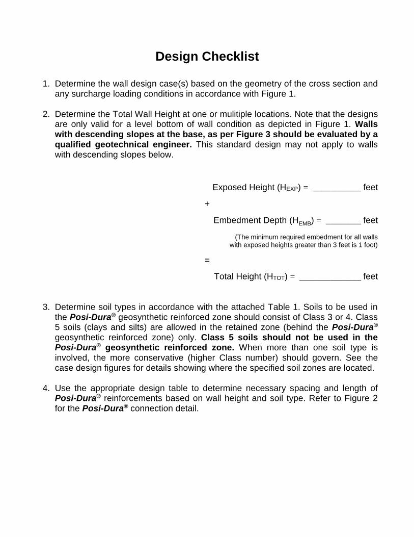
1. Determine the wall design case(s) based on the geometry of the cross section and any surcharge loading conditions in accordance with Figure 1.
2. Determine the Total Wall Height at one or mulitiple locations. Note that the designs are only valid for a level bottom of wall condition as depicted in Figure 1. Walls with descending slopes at the base, as per Figure 3 should be evaluated by a qualified geotechnical engineer. This standard design may not apply to walls with descending slopes below.
Exposed Height (HEXP) = ___________ feet
+
Embedment Depth (HEMB) = ________ feet
(The minimum required embedment for all walls with exposed heights greater than 3 feet is 1 foot)
=
Total Height (HTOT) = ______________ feet
3. Determine soil types in accordance with the attached Table 1. Soils to be used in the Posi-Dura® geosynthetic reinforced zone should consist of Class 3 or 4. Class 5 soils (clays and silts) are allowed in the retained zone (behind the Posi-Dura® geosynthetic reinforced zone) only. Class 5 soils should not be used in the Posi-Dura® geosynthetic reinforced zone. When more than one soil type is involved, the more conservative (higher Class number) should govern. See the case design figures for details showing where the specified soil zones are located.
4. Use the appropriate design table to determine necessary spacing and length of
Posi-Dura® reinforcements based on wall height and soil type. Refer to Figure 2 for the Posi-Dura® connection detail.

Posi-Dura® Installation Guidelines
The construction of the Verdura® 30 Retaining Wall with Posi-Dura® reinforcement is the same as the method presented on our website at www.soilretention.com. The following guidelines are intended as a supplement to the ICC-ES ESR-3073 report and website instructions when using the standard designs in this manual. Visit www.soilretention.com to view installation instructions and ICC report.
1. Determine the required spacing of the Posi-Dura® reinforcement. In general, Posi-Dura® reinforcement layers will be installed in every third course of blocks as depicted in Figure 1. Near the top of the wall, a maximum of three Verdura® 30 block courses may be placed above the last (or highest) reinforcement layer.
2. Each Verdura® 30 block in a reinforced course shall receive a Posi-Dura®
reinforcement strip. When the blocks are spaced 9” apart one Posi-Dura® reinforcement strip will be required every 2.25’ of wall length. The length of the Posi-Dura® reinforcement is determined by the appropriate design table for your site conditions and may be measured, cut, and installed as indicated in Case 1, Case 2, Case 3, and Figure 2.
3. An 11 ¼-inch long 1-inch diameter Schedule 80 PVC pipe shall be used to
anchor the Posi-Dura® reinforcement to the Verdura® 30 block. The pipe is inserted through a sleeve on the Posi-Dura® reinforcement and placed in the recess of the block between gussets prior to backfilling. Refer to Figure 2 for more information on the connection.
4. Posi-Dura® reinforcement layers should have a uniform length for each section
of wall with a fixed height.
5. Opposite end of geosynthetic may be staked in place or held taut until backfill soils are placed on top of Posi-Dura® reinforcement strips.

FIGURE 1 - WALL LOADING CASES
CASE ILEVEL BACKFILL
CASE IILEVEL BACKFILLTRAFFIC SURCHARGE
CASE III2:1 SLOPING BACKFILL

POSI-DURA REINFORCEMENT CONNECTION
SIDE VIEW
PLAN VIEW
SIDE VIEW
PLAN VIEW
POSI-DURA PIPE THROUGH POSI-DURA FABRIC CONNECTION
FIGURE 2 - POSI-DURA REINFORCEMENT DETAILS

FIGURE 3 - VERDURA RETAINING WALL WITH A VARYING SLOPE BELOW
NOTE:

CASE I Level Backfill
CLASS OF SOIL per Table I
TOTAL WALL HEIGHT (HTOT)
(feet) INCLUDING
EMBEDMENT
EXPOSED WALL
HEIGHT (HEXP) (feet)
EMBEDMENT DEPTH (HEMB)
(feet)
NUMBER OF POSI-DURA®
LAYERS
LENGTH OF POSI-DURA®
REINFORCEMENT (feet)
3 GW and GP
4.3 to 5.0 3.3 to 4.0 1.0 2 3.5
5.0 to 6.0 4.0 to 5.0 1.0 3 4.5
6.0 to 6.5 5.0 to 5.5 1.0 3 4.5
6.5 to 7.0 5.5 to 6.0 1.0 4 5.5
4
SW, SP, SM, SC, GM, and GC
4.3 to 5.0 3.3 to 4.0 1.0 2 3.5
5.0 to 6.0 4.0 to 5.0 1.0 3 4.5
6.0 to 6.5 5.0 to 5.5 1.0 3 5.5
6.5 to 7.0 5.5 to 6.0 1.0 4 6.5
5 CL, ML, MH,
and CH
4.3 to 5.0 3.3 to 4.0 1.0 2 3.5
5.0 to 6.0 4.0 to 5.0 1.0 3 4.5
6.0 to 6.5 5.0 to 5.5 1.0 3 5.5
6.5 to 7.0 5.5 to 6.0 1.0 4 6.5

TYPICAL CROSS SECTION THROUGH MAXIMUM HEIGHT
CASE ILEVEL BACKFILL
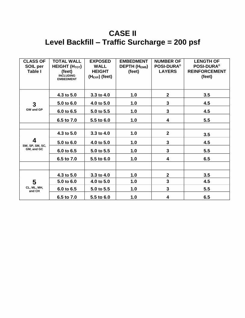
CASE II Level Backfill – Traffic Surcharge = 200 psf
CLASS OF SOIL per Table I
TOTAL WALL HEIGHT (HTOT)
(feet) INCLUDING
EMBEDMENT
EXPOSED WALL
HEIGHT (HEXP) (feet)
EMBEDMENT DEPTH (HEMB)
(feet)
NUMBER OF POSI-DURA®
LAYERS
LENGTH OF POSI-DURA®
REINFORCEMENT (feet)
3 GW and GP
4.3 to 5.0 3.3 to 4.0 1.0 2 3.5
5.0 to 6.0 4.0 to 5.0 1.0 3 4.5
6.0 to 6.5 5.0 to 5.5 1.0 3 4.5
6.5 to 7.0 5.5 to 6.0 1.0 4 5.5
4
SW, SP, SM, SC, GM, and GC
4.3 to 5.0 3.3 to 4.0 1.0 2 3.5
5.0 to 6.0 4.0 to 5.0 1.0 3 4.5
6.0 to 6.5 5.0 to 5.5 1.0 3 5.5
6.5 to 7.0 5.5 to 6.0 1.0 4 6.5
5 CL, ML, MH,
and CH
4.3 to 5.0 3.3 to 4.0 1.0 2 3.5
5.0 to 6.0 4.0 to 5.0 1.0 3 4.5
6.0 to 6.5 5.0 to 5.5 1.0 3 5.5
6.5 to 7.0 5.5 to 6.0 1.0 4 6.5

TYPICAL CROSS SECTION THROUGH MAXIMUM HEIGHT
CASE IILEVEL BACKFILLTRAFFIC SURCHARGE

CASE III 2:1 Sloping Backfill
CLASS OF SOIL per Table I
TOTAL WALL HEIGHT (HTOT)
(feet) INCLUDING
EMBEDMENT
EXPOSED WALL
HEIGHT (HEXP) (feet)
EMBEDMENT DEPTH (HEMB)
(feet)
NUMBER OF POSI-DURA®
LAYERS
LENGTH OF POSI-DURA®
REINFORCEMENT (feet)
3 GW and GP
4.3 to 5.0 3.3 to 4.0 1.0 2 4.5
5.0 to 6.0 4.0 to 5.0 1.0 3 5.5
6.0 to 6.5 5.0 to 5.5 1.0 3 6.5
6.5 to 7.0 5.5 to 6.0 1.0 4 7.5
4
SW, SP, SM, SC, GM, and GC
4.3 to 5.0 3.3 to 4.0 1.0 2 5.5
5.0 to 6.0 4.0 to 5.0 1.0 3 6.5
6.0 to 6.5 5.0 to 5.5 1.0 3 7.5
6.5 to 7.0 5.5 to 6.0 1.0 4 8.5
5 CL, ML, MH,
and CH
4.3 to 5.0 3.3 to 4.0 1.0 2 6.5
5.0 to 6.0 4.0 to 5.0 1.0 3 7.5
6.0 to 6.5 5.0 to 5.5 1.0 3 9.5
6.5 to 7.0 5.5 to 6.0 1.0 4 10.5

TYPICAL CROSS SECTION THROUGH MAXIMUM HEIGHT
CASE III2:1 SLOPING BACKFILL

TABLE I Soil Classifications
CONSULT A GEOTECHNICAL ENGINEER ON THE SOIL CLASSIFICATION FOR YOUR PROJECT.
USCS – UNIFIED SOIL CLASSIFICATION SYSTEM
CLASS OF SOIL PER TABLE 1806.2 OF CBC/IBC CODES
CLASS OF SOIL CLASS OF MATERIALS PER
USCS
DESCRIPTION
3
GW and GP
SANDY GRAVEL AND/OR GRAVEL
4
SW, SP, SM, SC, GM, and GC
SAND, SILTY SAND, CLAYEY SAND, SILTY GRAVEL & CLAYEY GRAVEL
5
CL, ML, MH, and CH
CLAY, SANDY CLAY, SILTY CLAY, CLAYEY SILT, SILT & SANDY SILT

Limitations
The designs presented herein are based on the use of the specified products manufactured by Soil Retention Products, Inc. and general soil types identified by the USCS and the 2013 California Building Code. It is the responsibility of the user of this design manual to verify the actual site soil conditions, and to construct the wall in accordance with this manual. A qualified geotechnical engineer should be retained to determine the soil type and any other geotechnical condition which may affect the design and stability of the wall and surrounding area, and to provide inspection services on a continuous basis during wall construction. The geotechnical engineer or his appointed representative shall observe and verify the installation of Verdura® blocks, geosynthetic reinforcement, and compaction of fill soil per ICC-ES ESR-3073 report. All fill soil should be compacted to at least 90% of ASTM D 1557 modified proctor density. The user of this design manual or his/her representatives agree, to the fullest extent permitted by law, to limit the liability of Soil Retention Products, Inc. and Soil Retention Designs, Inc. for any and all claims, losses, costs, damages of any nature whatsoever or claims expenses from any cause or causes, so that the total aggregate liability of Soil Retention Products, Inc. and Soil Retention Designs, Inc. shall not exceed $1,000.00 or the cost of wall materials, whichever is less. Such claims and causes include, but are not limited to negligence, professional errors or omissions, strict liability, breach of contract or warranty. The use of this design manual or his representatives also agree to fully protect, indemnify, hold harmless and defend Soil Retention Products, Inc. and Soil Retention Designs, Inc., their principles, officers, employees, and agents from and against any and all loss, cost, damage, injury, liability claims, liens, demands, taxes, penalties, interest or causes of action of every nature whatsoever resulting from the use of this design manual.