ver1 - freefly systems
TRANSCRIPT
VER1.0
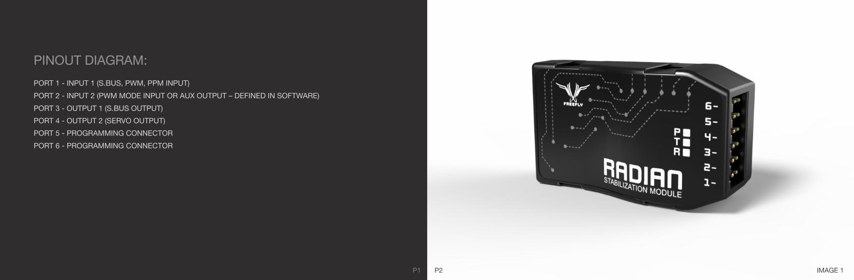
IMAGE 1P1 P2
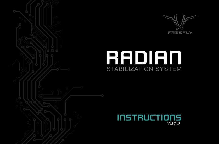
PINOUT DIAGRAM:
PORT 1 - INPUT 1 (S.BUS, PWM, PPM INPUT)
PORT 2 - INPUT 2 (PWM MODE INPUT OR AUX OUTPUT – DEFINED IN SOFTWARE)
PORT 3 - OUTPUT 1 (S.BUS OUTPUT)
PORT 4 - OUTPUT 2 (SERVO OUTPUT)
PORT 5 - PROGRAMMING CONNECTOR
PORT 6 - PROGRAMMING CONNECTOR
P4
STEP 1: MODULE MOUNTING / WIRING:
Mount the stabilization modules to the camera mount in the specified locations (see Images 2-6). It is very important to pay attention to the mounting orientation. The modules must be mounted as shown for proper operation. The roll, tilt, and pan modules are identical. The only difference is a software setting. Note that external potentiometers are no longer needed when using the Freefly Radian Stabilization System. To prepare the CineStar 2-axis and 3-axis gimbals for the stabilization modules, you must unplug the external potentiometers and install the resistors (included) into the servo lead that previously connected to the external potentiometer. Next, you will need to attach the Radian mounting plates for roll and tilt. Please ensure that the modules are rigidly attached to the camera mount. The sensors used in the system are very sensitive and it is important that they are firmly attached, so that they can accurately sense all the movements of the camera mount.
P5 P6
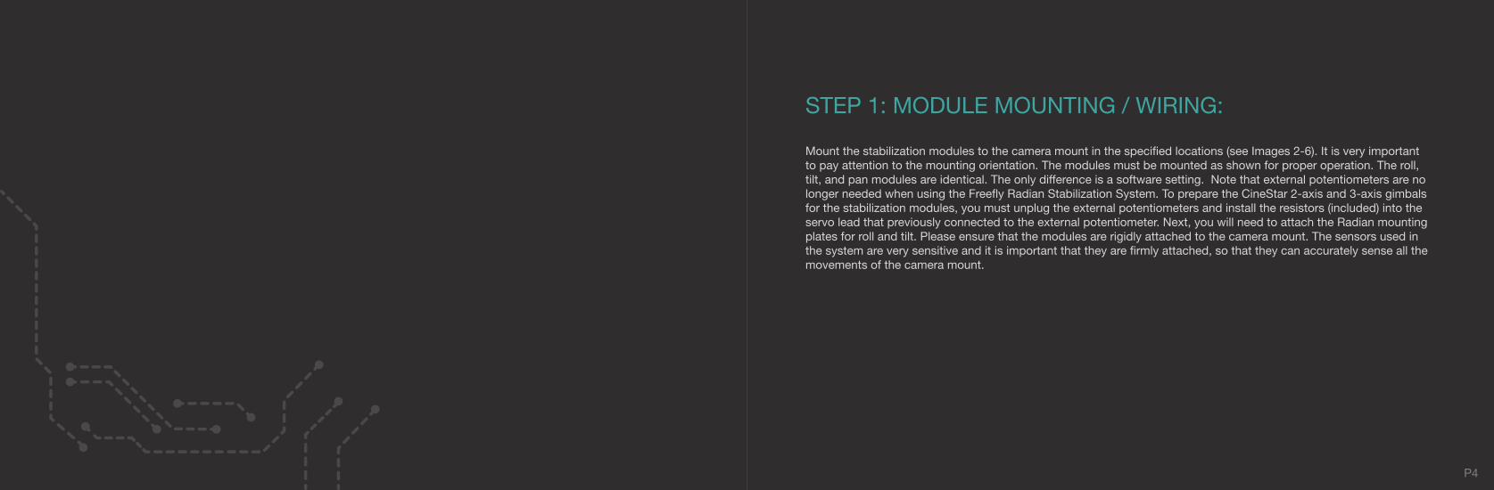
TILT MODULE MOUNTING PLATE INSTALLATION
• QTY 2 - M3X8MM THREADED STANDOFFS• QTY 4 - M3X6MM BUTTON HEAD SCREWS• QTY 1 - CARBON MOUNTING PLATE
IMAGE 2
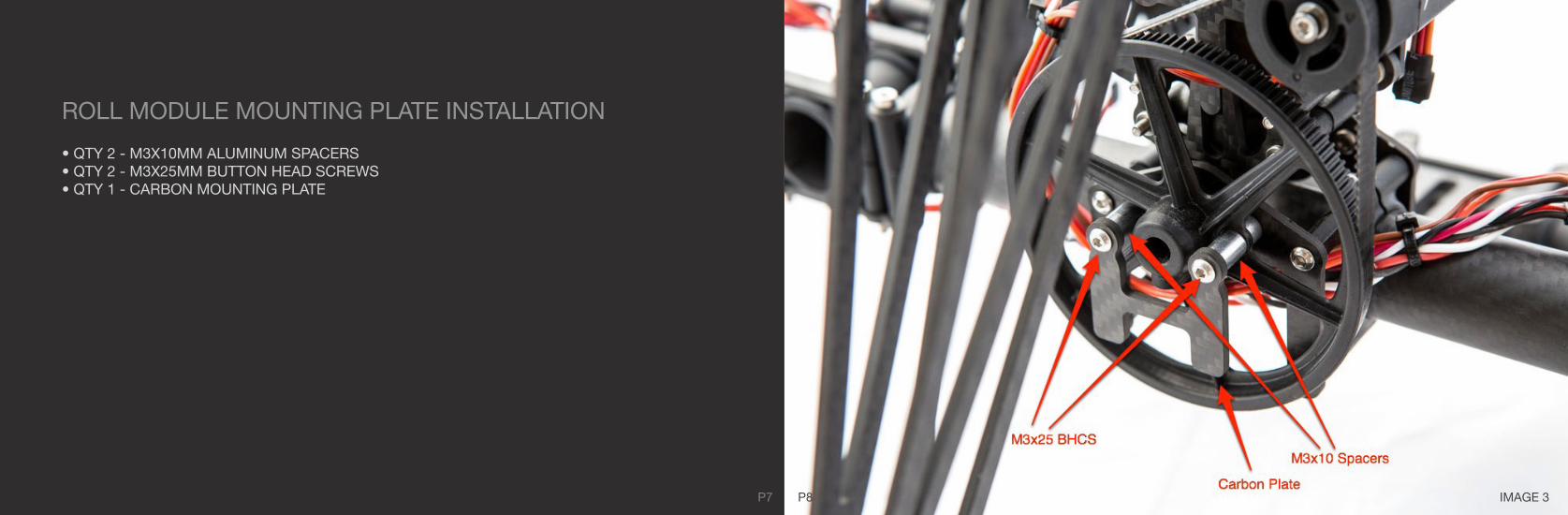
IMAGE 3P7 P8
ROLL MODULE MOUNTING PLATE INSTALLATION
• QTY 2 - M3X10MM ALUMINUM SPACERS• QTY 2 - M3X25MM BUTTON HEAD SCREWS• QTY 1 - CARBON MOUNTING PLATE

IMAGE 4
P9 P10
PAN MODULE INSTALLATION
Use the provided double stick adhesive to firmly attach the Radian to the carbon. Ensure the carbon is clean prior to attaching the double stick adhesive.

IMAGE 5
Use the provided double stick adhesive to firmly attach the Radian to the carbon mounting plate. Ensure the carbon is clean prior to attaching the double stick adhesive.
P11 P12
ROLL MODULE INSTALLATION
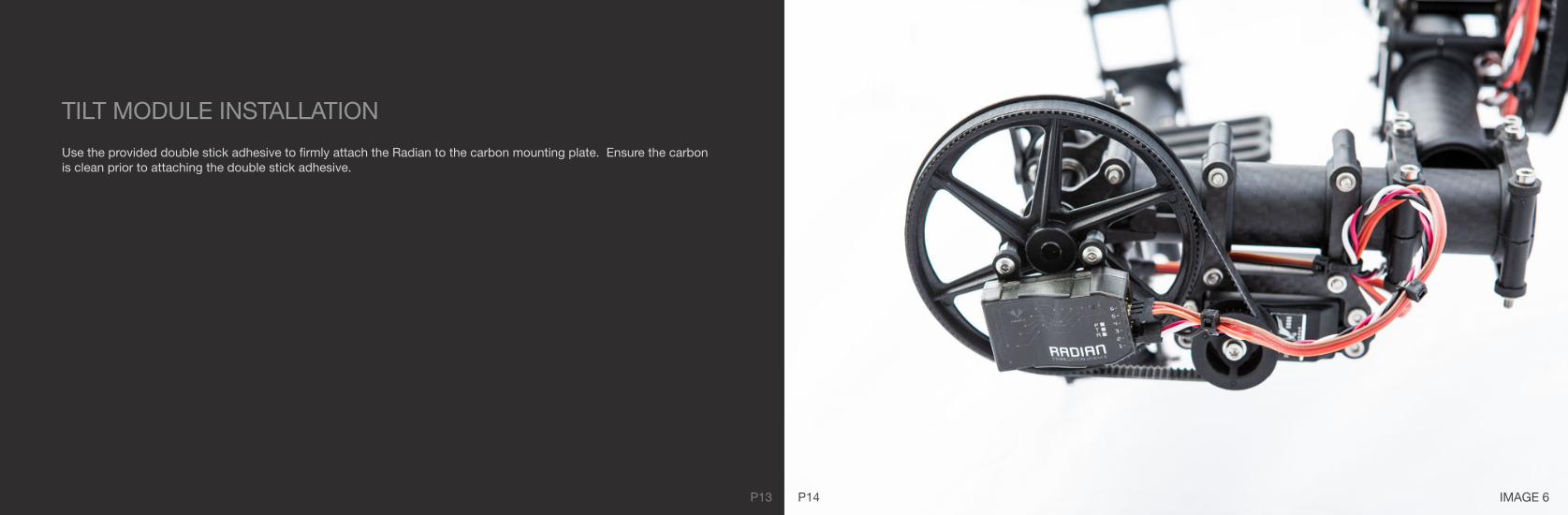
IMAGE 6
Use the provided double stick adhesive to firmly attach the Radian to the carbon mounting plate. Ensure the carbon is clean prior to attaching the double stick adhesive.
P13 P14
TILT MODULE INSTALLATION

P16
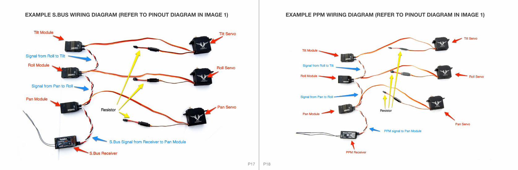
The wiring for the modules will depend on what type of receiver system you will use (PPM, PWM, S.Bus or Spektrum). PWM wiring will result in a more cluttered wiring layout; therefore, we recommend using S.Bus, PPM, or Spektrum over PWM. When using S.Bus, PPM or Spektrum, you are able to daisy chain the modules such that there only needs to be a connection from the mount receiver to the pan module. The pan module will then pass signal along to the roll module, which will pass it along to the tilt module. This allows for minimal wiring mess. Refer to the Pinout Diagram in Image 1 for the proper servo connector installation. If you are using PWM input (standard receiver), you will need a connection from each slew control channel to the corresponding module, as well as the mode input control from each channel. Note that PWM will require additional servo extensions (not included).
P17
EXAMPLE PPM WIRING DIAGRAM (REFER TO PINOUT DIAGRAM IN IMAGE 1)EXAMPLE S.BUS WIRING DIAGRAM (REFER TO PINOUT DIAGRAM IN IMAGE 1)
P18

EXAMPLE SPEKTRUM WIRING DIAGRAM (REFER TO PINOUT DIAGRAM IN IMAGE 1)EXAMPLE PWM WIRING DIAGRAM (REFER TO PINOUT DIAGRAM IN IMAGE 1)
P19 P20
P22
STEP 2: CAMERA BALANCING
Mount your camera to the gimbal in the same configuration you use for filming. Remove the tilt, roll, and pan belts from the CineStar gimbal. The goal is to balance the camera on the gimbal such that you can position the camera at any roll, tilt and pan angle and it will remain stationary. The normal workflow is to balance the tilt axis first, then the roll axis, and then the pan axis. To balance the pan axis, it is easiest to hang the multi-rotor from a boom end and adjust the gimbal forward and backward to achieve a good pan balance. Careful balancing will enhance stabilization performance and also allow higher gain settings so that they can accurately sense all the movements of the camera mount.

P23
STEP 3: CONNECTING USB PROGRAMMER
We recommend initially programming the stabilization modules with the servos unplugged, so that you can establish baseline settings without the camera gimbal moving. Connect the program cable to Ports 5 and 6 being careful to observe correct polarity (see Image 11).
IMAGE 11
P24

P25 P26
IMPORTANT:The Freefly USB to Serial Programmer (FFUSB) does not supply 5V power for the Radian. You will need to supply 5V power to the module in order to program. Attach the other end of the program cable to the FFUSB observing the polarity shown in Image 12. Using device manager in Windows, determine which COM port the FFUSB is using and then select the proper COM port in the Freefly Radian Stabilizer interface found under the Window > Comms Link toolbar. Click “Connect” on the diagnostics menu. The “Servo Out” slider will turn green if the connection is active.
TIP:The FFUSB programmer is set to default to COM10 port. If you go into your device manager and re-assign the device to “COM10,” then you will not have to select the COM port in the Radian software each time you use it.
IMAGE 12

P27
STEP 4: CHANNEL CONFIGURATION
Now the Input / Output configuration must be defined for each module. The preferred installationis using an S.Bus, Spektrum, or PPM receiver for minimal wiring and clutter; however, PWM connectivity is also supported.
S.BUS / PPM / SPEKTRUM INSTALLATIONPlease note we use S.Bus installation as an example below, but Spektrum and PPM installation would besimilar, with the only difference being using a PPM receiver or Spektrum satellite.
Connect your receiver’s S.Bus connection to the S.Bus input (Port 1) on the pan module. This is the onlyconnection that the stabilization system will need from the S.Bus receiver. The pan module will pass theS.Bus signal along to the roll and tilt modules. The modules may now be configured with your preferredchannel assignment for slew, mode, and Aux. The standard Freefly configuration for S.Bus receivers isbelow.
NOTE: PRIOR TO SETTING THE CHANNEL CONFIGURATIONS, IT IS IMPORTANT TO REVIEW THE INSTRUCTIONS AND INFORMATION INCLUDED UNDER STEP 5 - PARAMETER CONFIGURATION.
SLEW CHANNEL: 1MODE CHANNEL: 5 AUX: 0 (OFF)
PAN MODULE
SLEW CHANNEL: 0 MODE CHANNEL: 5 AUX: 0 (OFF)
ROLL MODULE
P28
P30
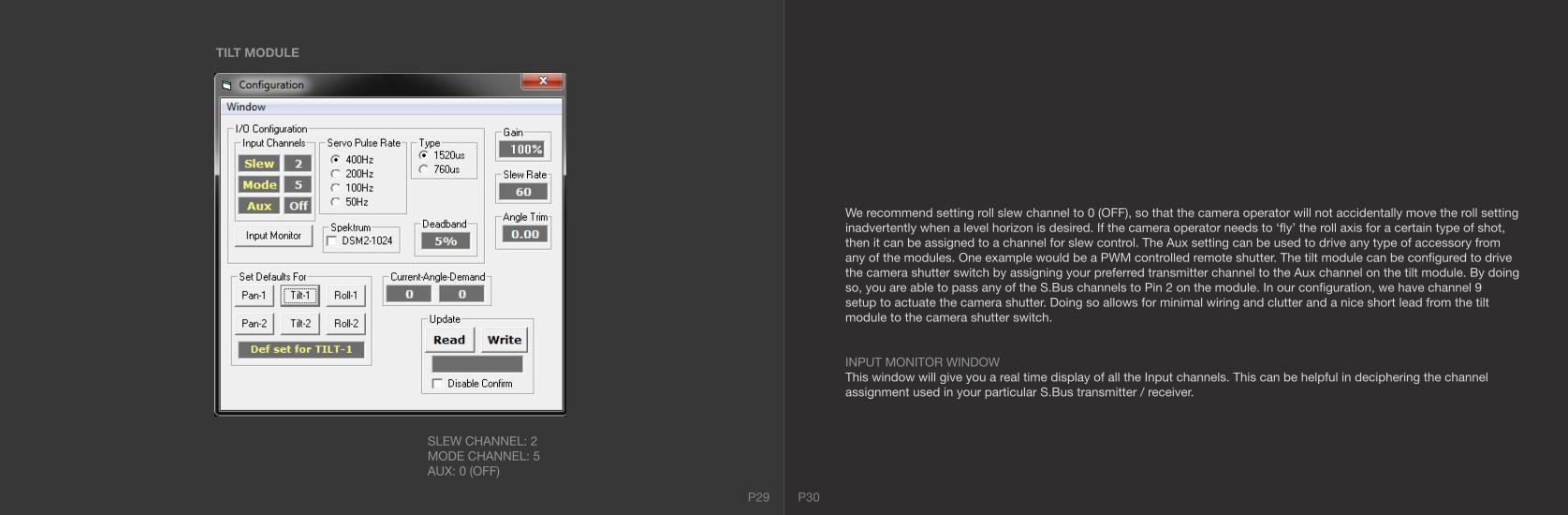
SLEW CHANNEL: 2MODE CHANNEL: 5 AUX: 0 (OFF)
TILT MODULE
We recommend setting roll slew channel to 0 (OFF), so that the camera operator will not accidentally move the roll setting inadvertently when a level horizon is desired. If the camera operator needs to ‘fly’ the roll axis for a certain type of shot, then it can be assigned to a channel for slew control. The Aux setting can be used to drive any type of accessory from any of the modules. One example would be a PWM controlled remote shutter. The tilt module can be configured to drive the camera shutter switch by assigning your preferred transmitter channel to the Aux channel on the tilt module. By doing so, you are able to pass any of the S.Bus channels to Pin 2 on the module. In our configuration, we have channel 9setup to actuate the camera shutter. Doing so allows for minimal wiring and clutter and a nice short lead from the tilt module to the camera shutter switch.
INPUT MONITOR WINDOWThis window will give you a real time display of all the Input channels. This can be helpful in deciphering the channelassignment used in your particular S.Bus transmitter / receiver.
P29

P32P31
STEP 5: PARAMETER CONFIGURATION
This is a visual guide to the proper programming sequence of the key fields. We will discuss eachoption in further detail on the next page.

P34P33
GAINThis is the primary adjustment setting for the module. Gain adjusts the force with which the stabilization module reacts to disturbances. Higher gain settings will cause a greater reactive force, but can also lead to instability in the system. The goal is to run the highest gain setting possible that is stable and has no oscillations. Start with a low gain setting and work your way up. A good way to test a particular gain setting is to gently ‘tap’ the axis you are tuning and see if it causes the mount to oscillate. If so, the gain is too high and needs to be lowered. NOTE: It is necessary to tune the modules in the way that they will be used in the air. For the 2-axis gimbal, this means you can tune the system with the multi-rotor sitting on the table since the gimbal is suspended by the vibration isolation system. On the 3-axis gimbal, however, the landing gear is built onto the gimbal, so it is necessary to hang the multi-rotor or suspend it by the booms, so that the gimbal will be suspended by the vibration isolation system while tuning. This will make a large difference in the tuning of the system, so please do not attempt to tune the 3-axis gimbal while it is sitting on the table, as the tuning will likely require much different gain parameters in flight. Remember to start with a low gain and work your way up. A nice way to tune the system is to have the transmitter next to your test stand and raise the gain little by little. If you get a setting that is too high and causes oscillations, you can simply switch the mode switch on the transmitter to “off” and lower the gain.
SLEW RATE This setting allows you to set the max slew rate for each axis. This will allow you to fine tune the feel of the system to your camera operator’s preferences. If you prefer to tune the slew rate remotely via the transmitter, this is possible using the ATV / AFR / Endpoints of your radio for the given slew channel. A slew rate setting of 60°/second is typically what we use. Further, you can setup multiple flight modes on the camera operator’s Tx to allow different slew rates for improved control in various filming scenarios.
ANGLE TRIM Angle trim allows for the fine tuning of a module to account for slight errors and offsets in the mounting. Angle trim is usually used on the roll axis to allow for slight trimming of the system to enable the user to set the system for a level horizon. Angle trim is not needed for pan or tilt modules.
DEFAULTS For each stabilization module, you will need to designate the module as either pan, tilt, or roll in the software. Until the software is installed, all of the modules are identical and may be mounted in any of the pan, tilt, or roll mounting locations. Please refer to Images 2-6 for proper mounting orientation. Whenever you connect to the modules, you MUST click “Read” first to populate the configuration window with the current module settings. Once the modules are in the proper mounting orientation, click “Read” and then click the appropriate default option. Next, enter your preferred configurations (see discussion below) and click “Write” to write the data to the module. To confirm that your mounting / chosen default is correct, rotate the mount in the corresponding direction for the module you are working on and ensure the “Current Angle” window is changing as expected. For instance, after installing the pan module, try rotating the mount. Given proper installation and chosen parameters, the “Current Angle” window will change as you rotate.
DEADBANDThe deadband setting adjusts how much stick travel is required before the stick demand creates a slew command. This setting can be useful if the transmitter gimbal does not center repeatably. Its function is to prevent unwanted axis drift. The default setting is 5%, but feel free to adjust as needed to suit your needs.
SERVO PULSE RATEThis setting adjusts the pulse rate output frequency for the mount stabilization. In general, it should be left at 400hz with Freefly Servos for best performance. For other mounts / servos, you may need to adjust the pulse rate.
SERVO TYPEThis setting allows the user to use a standard pulse width servo (1520uS) or a narrow pulse width (760uS) servo. The Freefly F360-0866 is a standard pulse width servo and the 1520uS setting should be used.

P36P35
VERY IMPORTANT:
Read / Write – Remember to use the “Read” / “Write” functions for each module. When you initially connect the programmer to the module, ensure you click “Read” to populate the configuration window with the current module settings. After making any changes to the configuration, click “Write” to write the new settings into the module.
STEP 6: MODE SWITCH
The mode switch is intended to be setup on a 3 position switch on the camera operator’s transmitter. Standard installation has the mode channel assigned in each module to the same input channel. This way the mode switch on the transmitter controls all the modules at once. In our installations, we assign mode to channel 5 and operate it via the 3 position switch C on a Futaba 8FG.
The 3 modes are:
OFF: This mode will stop driving the PWM output to the servos. This can be useful if there is a problem in flight that necessitates turning the mount off remotely (snagged wire, loose plug, etc.). Additionally, cycling the mode switch from “Off” to “On” and then back to the “Off” position will reset the system remotely.
FIXED POSITION STABILIZED: This mode will stabilize the roll and tilt modules, but not the pan module. This mode can be used for takeoff and landing, so that the CineStar will not spin around, which WILL happen if pan stabilization is active on takeoff and landing. Additionally, this mode can be used for a single operator flying the system where they do not need any slew commands. Fixed position stabilized will set the tilt angle to -5º tilt angle and 0º roll angle.
STABILIZED SLEW: This mode will activate the stabilization and the slewing on the pan, tilt, and roll modules. This is the mode that will be used when a camera operator needs to control the camera slew demands. This is the only mode in which pan stabilization will be active. It is important to not attempt to takeoff / land with a 3-axis gimbal in “Slew” mode, as the pan stabilization will cause the multi-rotor to spin around and could confuse the pilot. Only takeoff / land in “Off” and “Stabilized” modes.

P38P37
STEP 7: FLIGHT TUNING
Now that the programming and setup for the mount stabilization modules is complete, it is time for inflight tuning. After setting the gain on the bench, it is important to do some test flights to observe the operation of the stabilization system in the air. It can be helpful to tune one axis at a time.
PAN AXIS:For in-flight tuning, start with the pan axis. To test the pan module, yaw the multi-rotor and observe the 3-axis gimbal. The gimbal should smoothly stabilize and stay on its original heading regardless of what is done with the multi-rotor above it. Please be careful at first when using pan stabilization, as it can be very confusing for the pilot to observe the multi-rotor spinning above a stationary camera gimbal. It is a good idea to learn to only look at the multi-rotor for visual flight cues and not the gimbal. Once you turn on the stabilization / slewing on the 3-axis gimbal, the pilot and camera operator will be de-coupled and the camera operator and pilot can operate completely independently.
ROLL AXIS:With the pan axis tuned properly, we can move on to the roll axis. For roll axis, ensure that the camera is perfectly balanced. We want to be able to move the camera to any roll angle setting and have it stay at that setting without the tendency to swing back to neutral. Once the roll axis gain has been roughly tuned, we can do a test flight and observe the roll axis behavior. Over gain will often show as small twitches. If you see any of these symptoms, please lower the gain and test again. The proper gain setting will allow for fast and smooth stabilization with minimal twitches.
TILT AXIS:Tuning the tilt axis will largely depend on the length and inertia of the camera you are using. After setting an initial gain on the bench, do a test flight to ensure you do not have any over gain symptoms such as oscillations. After finding the setting that allows for smooth and fast stabilization, your 3-axis gimbal will be setup and ready for use. Please note that while the control algorithm on the stabilization system is quite robust, drastic changes to camera mass and balance (lens changes, etc.) may require further fine tuning of the system.

INITIALIZATION:NOTE: The stabilization module needs to sit perfectly still for 5 seconds when initially powered up. The best way for this to happen reliably is to power the mount with the camera mount transmitter set to the “OFF” position on the mode switch. This will prevent any of the axes from moving on power up and allow for accurate calibration.
LEDs:The LEDs give a visual indication of the module’s status as follows:
Orange LED fast blink = Initializing motor driveOrange LED slow blink: = IMU self-test faultGreen LED quick blink = IMU initializing (keep module perfectly still)Orange LED solid = S.Bus / Spektrum / PPM / signal validGreen LED slow blink = Motor drive off (or drive initialization failure)Both LED solid = Bootloader mode
ANGLE LIMITS:The stabilization system has programmed software limits of -110° to 10° on the tilt axis and -30° to 30° on the roll axis. Keep in mind these angles are relative to the ground reference, not the aircraft.
DISABLE CONFIRM:Checking this box will disable the warning message below:
P40P39

Thank you for purchasing the Freefly Systems Radian Stabilization System. Pleasecheck the Freefly forum regularly for updates, tips, and discussion at:
http://forum.freeflysystems.com