venturi type bubble generator for use - … · ornl-tm-4122 ccntract no. w-7405-eng-26 reactor...
TRANSCRIPT

ORNL-TM-4122'
DEVELOPMENT OF A
VENTURI T Y P E B U B B L E GENERATOR FOR USE
IN T H E MQLTEN-SA,LT REACTOR XENON
REMOVA,L SYSTEM
C. H . Gabbard
MASTER '
This report was prepared as an account of work sponsored by the United States Government. Neither the United States nor the United States Atomic Energy Commission, nor any of their employees, nor any of their contractors, subcontractors, or their employees, makes any warranty, express or implied, or assumes any legal liability or responsibility for the accuracy, completeness or usefulness of any informatton, apparatus, product or process disclosed, or represents that its use would not infringe privately owned rights.
ORNL-TM-4122
Ccntract No. W-7405-eng-26
Reactor Divis ion
DEVELOPMENT OF A VENTURI TYPE BUBBLE GENERATOR FOR USE I N THE MOLTEN-SALT REACTOR XENON REMOVAL SYSTEM
C . H . Gabbard
Molt en- S a l t React o r Program
This report contains information of a prel iminary nature and was prepared pr imari ly for internal use at the originating installation. It is subject to re- vision o r correction and therefore does not repre- sent a final report . It is passed t o the recipient in confidence and should not be abstracted or fur ther disclosed without the approval of the originating installation or DTI Extension, Oak Ridge.
December 1972
OAK RIDGE NATIOFAL LABORATORY Oak Ridge, Tennessee 37830
operated by U N I O N CARBIDE CORPORATION
f o r t h e U.S. ATOMIC ENERGY COMMISSION
N O T I C E
sponsored by the United States Government. Neither the United States nor the United States Atomic Energy Commission, nor any of their employees, nor any of their contractors, subcontractors, or their employees, makes any warranty, express or implied, or assumes any legal liability or responsibility for the accuracy, com- pleteness or usefulness of any information, apparatus, product or process disclosed, or represents that its use would not infringe privately owned rights.
This report was prepared as


iii
T A B L E OF CONTENTS
ABSTRACT
I. INTRODUCTION
11. BUBBLE GENERATOR D E S I G N
111. O P E R A T I N G C H A R A C T E B I S T I C S AND TEST R E S U L T S
III.-l. Bubble Size!
111.-2. G a s I n j e c t i o n Pressure C h a r a c t e r i s t i c s
I V . C O N C L U S I O N S AND RECOMMENDATIONS
V. ACKNOWLEDGEMENT
NOMENCLATURE
R E F E R E N C E S
A P P E N D I X
Page
1
1
2
5
7
1 4
27
28
24
30
31


LIST OF FIGURES
Page
4 F igure 1. Bubble Generator Design Configurat ions which were Given Reduced Sca le Evaluat ion Tes t s
F igure 2. Bubble Generator Design for t h e Gas Systems Technology Fac i i l i ty
6
Figure 3. Bubble S ize Produced by 2 . 1 i n . Throat Diameter 9 Bubble Generator as a Function of Liquid Flow Rate
Figure 4. Bubble S ize Produced by GSTF Bubble Generator 1 0 as a Function of Surface Tension
Figure 5 . Surface Tension as a Funct ion of Sodium Oleate Concentrat ion for Laboratory Batch Samples and f o r Loop Samp1.e~
Bubble S ize Cor re l a t ion f o r GSTF Design Bubble Generator
F igure 6.
11
16
Figure 7. Simpl i f ied Flow Diagram of t h e Gas Systems Technology 16 F a c i l i t y
F igure 8. Gas I n j e c t i o n Pressure and Overa l l Pressure Drop 17 of Prototype Bubble Generator as a Function of Gas Flow F a t e
F igure 9 . Geometry of Bubble Generator Used i n Analysis of 19 Gas I n j e c t i o n Pressure and Overa l l Head Loss
F igure 10. Pressure Drop of Gas Feed Passages as a Function 22 of Gas Flow Rate
Figure 11. Pressure Drop Across t h e Gas Plume I n t e r f a c e as a Function of Throat Void F rac t ion
24
Figure 12 . Cor re l a t ion of' Plume AH ( H 6 ) t o Throat Liquid Veloc i ty and Throat Void F rac t ion
25

t
DEVELOPMENT OF A VENTURI TYPE BUBBLE GENERATOR FOR USE I N THE MCLTEN-SALT REACTOR XENON REMOVAL SYSTEM
C . H . Gabbard
ABSTRACT
A v e n t u r i t ype bubble genera tor was developed f o r app l i - c a t i o n i n t h e xenon removal system proposed f o r - a molten-salt breeder r e a c t o r . Gas i n j e c t e d i n t o t h e high v e l o c i t y l i q u i d at thekventur i throa,t i s formed i n t o bubbles by t h e f l u i d turbulence i n t h e d i f f u s e r cone. T e s t s were conducted us ing aqueous s o l u t i o n s tcl determine t h e var ious p re s su re drops of t h e bubble generator as a func t ion of l i q u i d and gas flow rates and t o determine t h e bubble diameter produced. Empir ical r e l a t i o n s k i p s were developed which could b e used i n combination wi th t h e more convent ional f l u i d flow equat ions t o p r e d i c t t h e o v e r e l l head l o s s and t h e gas i n j e c t i o n pres- s u r e o f t h e bubble genera tor . A dimensionless c o r r e l a t i o n f o r p r e d i c t i n g t h e ‘tiubble diameter w a s developed f o r bubble genera tors of s i m i l a r geometry.
- -..___
Keywords : Bubtile Generator, Bubble:;, Bubble S ize , Gas I n j e c t i o n , Fused S a l t s , MSBE, MSBR, Performance, Xenon, F lu id Flow.
I. INTRODUCTION
In a nuc lear r e a c t o r ope ra t ing i n t h e thermal energy range , t h e con-
t inuous removal of t h e geseous f i s s i o n product poison xenon-135 i s neces-
s a r y t o ob ta in a breeding r a t i o g r e a t e r t han l . 0 .
b reeder r e a c t o r (MSBR), t h e xenon-135 c i r c u l a t e s i n s o l u t i o n wi th t h e
molten f l u o r i d e f u e l salt, . A proposed method of removing t h i s xenon i s
t o cont inuously i n j e c t helium bubbles i n t o t h e sal t stream t o a gas
volume f r a c t i o n of 0 .2 t o 1 .0 percent a t t h e r e a c t o r co re midplane.
xenon-135 would t r a n s f e r by t u r b u l e n t d i f f u s i o n and would be s t r i p p e d
from t h e sa l t when t h e bubbles were removed. Calcu la t ions i n d i c a t e t h a t ,
even with t h i s l o w gas volume f r a c t i o n , adequate xenon-135 removal would
be obta ined by s t r i p p i n g t h e bubbles from a bypass stream which i s about
10 percent of t h e main sa l t flow.
s t r i p p i n g l a r g e r f lows ,
a MSBR by t h i s method i s presented i n Reference (1).
I n a molten-sal t
The
L i t t l e advantage would be gained by
A more complete d i scuss ion o f xenon removal from

2
This r epor t desc r ibes t h e des ign , development, and ope ra t ing char-
a c t e r i s t i c s of t h e bubble genera tor proposed f o r use i n a 150 M W ( t )
mol ten-sal t b reeder experiment (MSBE) . ( 2 )
of t h i s bubble genera tor was s tud ied i n a t e s t f a c i l i t y u s ing water,
glycer in-water mixtures , and C a C 1 2 aqueous s o l u t i o n s .
o f Has te l loy "N" w i l l be fur ther eva lua ted with molten sa l t as p a r t of
t h e t es t program o f t h e Gas System Technology F a c i l i t y (GSTF).
A f u l l s c a l e P lex ig l a s model L
A pro to type model
( 3 )
11. BUBBLE GENERATOR DESIGN
The ultimate goa l of t h e development program w a s t o o b t a i n informa-
t i o n which could be used t o design a f u l l s c a l e bubble genera tor which
could be tes ted i n t h e GSTF us ing molten salt.
t h a t have evolved dur ing t h e development of t h e bubble genera tor a r e
l i s t e d i n Table I.
parts w e r e considered o r i g i n a l l y but w e r e r e j e c t e d as be ing unnecessar i ly
complex f o r a high-temperature molten-sal t system, F lu id powered devices
b a s i c a l l y resembling flow ven tu r i appeared t o s a t i s f y t h e c r i t e r i a a d
t h r e e conf igura t ions were s e l e c t e d f o r continued development, The d i f -
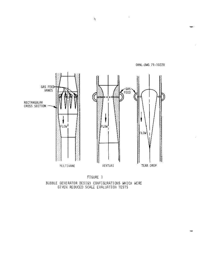
f e r e n t conf igura t ions , shown i n Figure 1, are v a r i a t i o n s i n t h e method of
forming t h e high v e l o c i t y t h r o a t reg ion ,
v e l o c i t y sal t s t ream a t t h e t h r o a t forms small bubbles as a r e s u l t of t h e
f l u i d turbulence i n t h e d i f f u s e r s ec t ion .
Severa l design c r i t e r i a
Devices r equ i r ing a u x i l i a r y power.or having moving
Helium i n j e c t e d i n t o t h e high
Reduced s c a l e t es t s were performed on t h e s e t h r e e conf igura t ions arid
each performed s a t i s f a c t o r i l y ,
i nd ica t ed t h a t t h e r e s u l t i n g bubble s i z e w a s about one-fourth of t h e sa l t
flow gap over t h e range of l i q u i d flows t e s t e d .
passage o f 0.080 i n . would be requi red t o produce 0.020 i n . Ciameter
bubbles . The "mul5ivane" design w a s an extension of t h i s p r i n c i p l e t o
provide a more uniform bubble Ciis t r ibut ion over l a r g e r p ipe s i z e s and t o
avoid t h e l a r g e diameter t h a t would have been requi red i n a full s c a l e
t ea rd rop design wi th a 0.080 i n . annulus.
revea led a flow o s c i l l a t i o n around t h e t r a i l i n g edge of t h e vane. I n
a d d i t i o n , t h e gas d i s t r i b u t i o n along t h e width of t h e vane and between
t h e flow passages on e i t h e r side of t h e vane was d i f f i c u l t t o con t ro l .
Reduced s c a l e t e s t s on t h e "ventur i" design were performed us ing 3/4 i n .
and 1 1 / 2 i n . pipe s i ze commercial j e t pumps t h a t were modified t o more
I n i t i a l t e s t i n g of t h e " teardrop" design
Consequently , a flow (4)
Tes t s of a s i n g l e vane pro to type

3
Table I
Bubble Generator C r i t e r i a
1. The bubble genera tor should be s i z e d f o r a p p l i c a t i o n i n t h e MSBE .
2 . Nominal sa l t flow rate = 500 gpm.
3. Gas flow r a t e = 0 - 10.65 scfm helium.
4. The generated bubble diameter should be 0.020 i n . o r l ess .
5 . The gas bubbles should be uniformly d ispersed i n t h e flowing sal t s t ream.
6 . The bubble generat ,or should be s imple, r e l i a b l e , and maintenance-free .
7. The bubble genera tor should opera te from p res su re drop inhe ren t i n t h e o v e r a l l systeix design and should not r e q u i r e a gas corn- p re s su re f o r t h e i n j e c t i o n of gas .
ORNL-DWG 71 -1 0220
FlULT I VANE VENTURI TEAR DROP
FIGURE 1 BUBBLE GENERATOR DESIGN CONFIGURATIONS WHICH WERE
G I V E N REDUCED SCALE E V A L U A T I O N TESTS
5
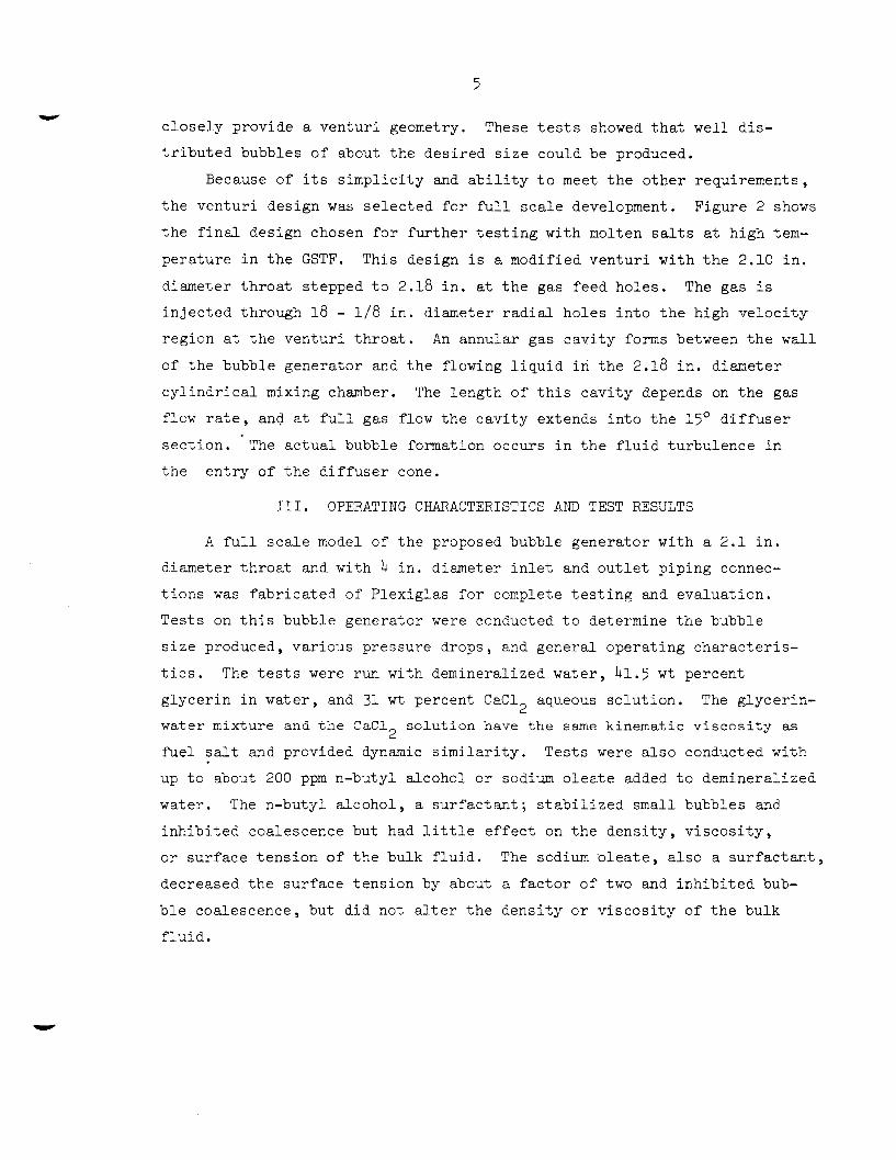
I c l o s e l y provide a ven tu r i geometry. These t e s t s showed t h a t w e l l d i s -
t r i b u t e d bubbles of about t h e des i r ed s i z e could be produced.
Because of i t s s i m p l i c i t y and a b i l i t y t o meet t h e o t h e r requirements ,
t h e v e n t u r i design w a s s e l e c t e d f o r f u l l s c a l e development.
t h e f i n a l design chosen fDr f u r t h e r t e s t i n g wi th molten sal ts a t high t e m -
pe ra tu re i n t h e GSTF. This design i s a modified v e n t u r i wi th t h e 2.10 i n .
diameter t h r o a t s tepped t o 2.18 i n . a t t h e gas feed ho le s .
i n j e c t e d through 18 - 1/8 i n . diameter r a d i a l ho les i n t o t h e high v e l o c i t y
reg ion a t t h e v e n t u r i t h r o a t .
of t h e bubble genera tor and t h e flowing l iqu id . i n t h e 2.18 i n . diameter
c y l i n d r i c a l mixing chamber.
flow r a t e , and a t f u l l gas flow t h e c a v i t y extends i n t o t h e 15O d i f f u s e r
s e c t i o n . The a c t u a l bubble formation occurs i n t h e f l u i d turbulence i n
t h e e n t r y of t h e d i f f u s e r cone.
F igure 2 shows
The gas i s
An annular gas c a v i t y forms between t h e w a l l
The l eng th of t h i s c a v i t y depends on t h e gas
111. OPERATING CHARACTERISTICS AI’3D TEST RESULTS
A f u l l s c a l e model of t h e proposed bubble genera tor wi th a 2 . 1 i n .
diameter t h r o a t and wi th 4 i n . diameter i n l e t and o u t l e t p ip ing connec-
t i o n s w a s f a b r i c a t e d of Plex ig la s f o r complete t e s t i n g and eva lua t i cn .
Tes t s on t h i s bubble genera tor were conducted t o determine t h e bubble
s i z e produced, va r ious pressure drops , and genera l ope ra t ing c h a r a c t e r i s -
t i c s .
g lyce r in i n wa te r , and 31 w t percent C a C 1 2 aqueous s o l u t i o n .
water mixture and t h e C a C l s o l u t i o n have t h e same kinematic v i s c o s i t y as
f u e l s a l t and provided dynamic s i m i l a r i t y .
The t e s t s were run wi th demineralized water , 4 1 . 5 w t percent
The g lycer in-
2 Tes t s were a l s o conducted wi th
up t o about 200 ppm n-butyl a lcohol o r sodium o l e a t e added t o demineral ized
water. The n-butyl a l coho l , a s u r f a c t a n t ; s t a b i l i z e d small bubbles and
i n h i b i t e d coalescence but had l i t t l e e f f e c t on t h e dens i ty , v i s c o s i t y , o r su r face t e n s i o n of t h e bulk f l u i d . The sodium‘olea te , a l s o a s u r f a c t a n t ,
decreased t h e su r face t e n s i o n by about a f a c t o r of two and i n h i b i t e d bub-
b l e coalescence, bu t d id not a l t e r t h e dens i ty o r v i s c o s i t y of t h e bulk
f l u i d .

ORNL-DWG 72-9609
,-GAS INJECTION LINE ,, ’ 3/4-in. OD x 0.072- in.
WALL TUBING
5.047 in - FLOW
‘ I ANNULAR GAS DISTRIBUTION,,
~
p- 4’546 in.- CHANNEL 34 in. x 543 in. I
4 _ _ - -19 5/32 in. ~-
I
~
I
5.047 in. diam
1
FIGURE 2
BUBBLE GENERATOR DESIGN FOR THE GAS SYSTEMS TECHNOLOGY F A C I L I T Y

7
III.-l. Bubble Size,
III.-1.1 Test Condition
I n t h e proposed xenon removal system, helium bubbles are t o be
i n j e c t e d and removed i n a 1 0 percent bypass loop. The bubbles on t h e
average a r e expected t o c i r c u l a t e s e v e r a l times around t h e primary c i r -
c u i t o f t h e r e a c t o r be fo re being processed i n t h e s i d e stream. During
t h i s c i r c u l a t i o n , t h e bubbles w i l l be a f f e c t e d by s o l u t i o n and d i s s o l u t i o n
as they pass through d i f f e r e n t reg ions of pressure and tempera ture , and
by breakup arid coalescence as they pass through high and low shear reg ions
( e . g . , t h e pump).
be c o n t r o l l e d by t h e system dynamics r a t h e r t han by t h e bubble genera tor
i t s e l f . However t h e s i z e genera t ion c h a r a c t e r i s t i c s of t h e bubble gen-
e r a t o r should be of genera l i n t e r e s t f o r o t h e r systems and f o r p o s s i b l e
unan t i c ipa t ed modes of ope ra t ion , such as f u l l f low gas i n j e c t i o n and
removal.
condi t ion f o r monitor ing 2hanges as t h e bubbles pass through t h e system.
Consequently, some ana lys i s and some l i m i t e d t e s t s were made t o o b t a i n
an i n d i c a t i o n of t h e bubb.le s i z e produced by t h e bubble genera tor as it
i s a f f e c t e d by flow and f l u i d p r o p e r t i e s . Flow r a t e w a s v a r i e d from
200 gpm t o 550 gpm and su r face t ens ion w a s va r i ed from 72 dynes/cm t o
230 dynes/cm by adding d i f f e r e n t amounts of sodium o l e a t e .
agen t , G.E. S i l i c o n e Jbu l s ion AF-72, was a l s o added a t c o n c e n t r a t i m s of
1 0 percent of t h e sodium o l e a t e .
ConseqJently, t h e c i r cu lAt ing bubble s i z e i s l i k e l y t o
I n add i t ion , t h k s i ze produced may serve as an " i n i t i a l i z i n g "
An antifoaming
III.-1.2 Bubble S ize Measurements -- The bubble s i z e d i s t r i b u t i o n s produced by t h e bubble genera tor were
determined by t ak ing s t i l l photographs a t t h e d ischarge of t h e d i f f u s e r
coce. A convent ional s t u d i o camera wi th a 1 2 i n . f o c a l l eng th l e n s was
used t o t a k e t h e photogrcphs on 4x5 Polaro id f i l m . A s t r o b e l i g h t with a
1/30,000 secocd du ra t ion w a s used t o "stop" t h e bubble motion and t o pro-
v ide back l i g h t i n g .
The photographs , which were about a c t u a l s i z e , were enlarged t o
o b t a i n a t o t a l magni f ica t ion of 8. Enlargements t o g r e a t e r magni f ica t ion
r e s u l t e d i n a loss of r e s o l u t i o n . 'The bubble s i z e d i s t r i b u t i o n s f o r each
condi t ion were determined by s c a l i n g bubble s i z e s d i r e c t l y from t h e

8
enlargements.
t empla te having d r i l l e d ho le s ranging from 1/32 t o 3/4 i n . i n increments
of 1 / 3 2 i n . A volume averaged bubble diameter as de f ined below w a s ca l -
c u l a t e d f o r each d i s t r i b u t i o n :
The diameters were measured by comparison wi th a p l a s t i c
where: n
d pe r u n i t area of t h e photograph.
i s t h e number o f bubbles of a given diameter, i
i' The r e s o l u t i o n of t h e photographs w a s adequate t o measure bubble diameters
i n t h e 0.008 i n . range (1/16 i n , on t h e enlargement) , bu t no bubbles
could be i d e n t i f i e d i n t h e 0.004 i n . diameter range ,
tes ts a r e shown on Figures 3 and 4. The results o f t hese
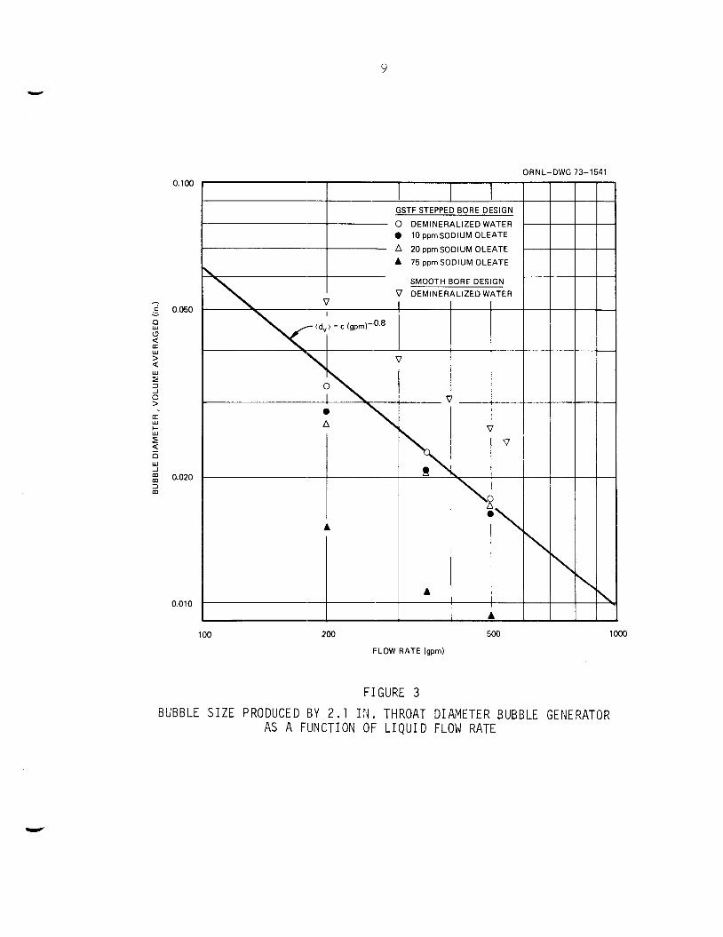
Figure 3 shows t h e volume average bubble diameter produced by two
bubble genera tor designs p l o t t e d as a func t ion of l i q u i d flow rate a t
several va lues of su r face t ens ion . The data are compared wi th a s lope of
-0.8 power dependence d iscussed i n g r e a t e r de t a i l l a t e r i n t h i s r e p o r t .
There w a s a high degree of s c a t t e r i n some of the s e t s of data a t cons tan t
su r f ace t ens ion , Consequently, only s e l e c t e d data sets having low s c a t t e r
are shown on t h e p l o t .
t h e va r ious l i n e s , t h e data t end t o support a -0.8 power dependence.
S imi l a r data taken previous ly a l s o support a -0.8 power, and none of t h e
data have suggested a s lope s i g n i f i c a n t l y d i f f e r e n t from -0.8.
Although t h e r e were d i f f e r e n c e s i n t h e s lope of
F igure 4 i s a p l o t of t h e bubble diameter as a func t ion of s u r f a c e
t e n s i o n a t t h r e e flow ra tes , The measured s u r f a c e t e n s i o n data from
loop samples taken during t h e course o f t h i s experiment were s c a t t e r e d
and d i d not agree wi th t h e data from previous l abora to ry s c a l e samples
which were i n genera l agreement w i t h t h e sodium o l e a t e s u p p l i e r ' s l i t e r a -
t u r e .
t h e c a l c u l a t e d concent ra t ions i n t h e t e s t loop and t h e su r face t e n s i o n
vs concent ra t ion data from t h e l abora to ry samples as shown on Figure 5 . The measured su r face t ens ion data from t h e loop samples are a l s o shown
on Figure 5 . However, t h e a c t u a l c i r c u l a t i n g concent ra t ion of sodium o l e a t e could change
The values of su r face t e n s i o n used i n Figure 4 were obta ined from
The discrepancy between t h e s e i s not f u l l y understood. -
9
ORNL-DWG 73-1541 0.100
- ,* 0.050 - E 2 (3
W > < 5
0 > a
t, z P n
: 0.020
w
3
w
w -I
3 m
GSTF STEPPED BORE DESIGN
0 DEMINERALIZED WATER 0 10 ppmSODlUM OLEATE
A 20 ppm SODIUM OLEATE A 75 ppm SODIUM OLEATE
SMOOTH BORE DESIGN
A
0'010 I 4 100 200
A
I I A
500
FLOW RATE (gprn)
FIGURE 3
lo00
BUBBLE S I Z E PRODUCED BY 2.1 II4. THROAT DIAMETER BUBBLE GENERATOR AS A FUNCTION OF L I Q U I D FLOW RATE

ORNL-DWG 73-1542 1 0.060 ,
,
0.050
0.040
0.030
0.010
A LIQUID FLOWRATE = 200 gprn
0 0
LIQUID FLOWRATE = 350 gprn
LIQUID FLOWRATE = 500 gprn
a a
A
I 0 0.009
0 0
4 0
0
10 20 30 40 50 60 70 80 90 100
SURFACE TENSION (dynedcrn)
F IGURE 4
BUBBLE S I Z E PRODUCED BY GSTF BUBBLE GENERATOR AS A FUNCTIOTJ OF SURFACE T E N S I O N
P 0

flRNl -l-lWG 7?.--15X2 _ . . - - . . - , - ---
30
20
0 LABORATORY SAMPLES
0 LOOP SAMPLES
0 0
l - O-0 I-T---
-
0 20 40 60 80 100 120 140 160 180 200
CONCENTRATION OF SODIUM OLEATE (ppmj
FIGURE 5
SURFACE TENS1014 AS A FUNCTION OF SODIUM OLEATE CONCENTRATION FOR LABORATORY BATCH SAMPLES AND FOR LOOP SAMPLES

12
during a given t e s t run because t h e sodium o l e a t e , being a s u r f a c t a n t , would be s t r i p p e d from t h e c i r c u l a t i n g loop along wi th t h e bubbles. The
concent ra t ion i n t h e loop samples could then be l e s s t han t h e ca l cu la t ed
average concent ra t icn for t h e e n t i r e loop depending on t h e t ime t h e samples
were taken.
w a s s t a r t e d fol lowing an hour ' s c i r c u l a t i o n without gas flow. This proce-
dure should have provided a concent ra t ion of sodium o l e a t e e s s e n t i a l l y
equal t o t h e ca l cu la t ed average a t t h e t i m e t h e photographs were taken .
The bubble photographs were taken immediately a f t e r gas flow
The bubble diameter d a t a of Figure 4 are t o o s c a t t e r e d t o accu ra t e ly
However, t h e d a t a t end t o support determine t h e a c t u a l power dependence.
a va lue c f 0 .6 as p red ic t ed by t h e t h e o r e t i c a l cons ide ra t ions d iscussed
below and as i l l u s t r a t e d on Figure 4.
111.-1.3 Analysis of Bubble S ize Data
The bubbles produced by t h e bubble genera tor a r e apparent ly formed
i n t h e en t rance reg ion of t h e conica l d i f f u s e r as a resu l t of f l u i d t u r -
bulence. The fol lowing equat ion has been proposed t o p r e d i c t t h e s i z e of
gas bubbles produced by f l u i d turbulence .
Equation (1) w a s used by Hinze") t o c a l c u l a t e d rop le t diameters produced
by emuls i f i ca t ion of one l i q u i d i n another i n an i so t rop ic - tu rbu len t
flow f i e l d .
t h a t t h e f r i c t i o n f a c t o r would be cons t an t , t h e power d i s s i p a t i o n p e r
u n i t volume ( E ) can be expressed as:
Assuming tu rbu len t flow i n a condui t wi th condi t ions such
(6)
3 3
( 2 ) ' NRe € = k 2
p D~~ gc
S u b s t i t u t i n g t h i s r e l a t i o n s h i p f o r t h e power d i s s i p a t i o n , Squation (1)
gives :
V
13
The
315 en t
bubble s i z e d a t a presented i n Figures 3 and 4 gene ra l ly confirm a
power dependence f o r t h e su r face t ens ion term, but i n d i c a t e an expon-
of -0.8 f o r t h e Reynolds Number t e r m r a t h e r than -1.2 as ind ica t ed by
Equation ( 3 ) . sugges ts a r e l a t i o n d i f f e r e n t from Equation ( 2 ) f o r t h e power d i s s i p a t i o n
r a t e i n t h e bubble genera t ion reg ion of our device.
apply when power i s added t o t h e f l u i d cont inuously as i n an a g i t a t e d tank
This would t end t o confirm t h e form of Equation (1) , but
Equation ( 3 ) might
or i n p i p e l i n e flow where t h e f r i c t i o n l o s s e s represent a continuous energy
d i s s i p a t i o n wi th in t h e f l u i d . I n t h e present bubble gene ra to r , t h e f l u i d
may r ece ive an "energy impl se ' l as some of t h e k i n e t i c energy of t h e high
v e l o c i t y f l u i d i n t h e t h r c a t i s converted t o f l u i d turbulence i n t h e d i f -
f u s e r , and t h e above equat ions may not apply s p e c i f i c a l l y f o r t h i s mechan-
isr,.
An a l t e r n a t e expression f o r t h e power d i s s i p a t i o n r a t e based on t h e
w a l l shear stress has been proposed by Kress" f o r t h e GSTF bubble genera-
t o r design. Using h i s prcposed r e l a t i o n f o r power d i s s i p a t i o n , Equation
(1) gives t h e fol lowing r e l a t i o n s h i p p red ic t ing a 3 /5 power dependence
on su r face t ens ion and a -415 power dependence on t h e Reynolds number
as observed.
A t t h e present t ime, t h e r e a r e i n s u f f i c i e n t data t o v e r i f y Equation (4) because only t h e l i q u i d v e l o c i t y and l i q u i d su r face t ens ion have been
va r i ed . Therefore , w e have e l e c t e d t o empir ica l ly c o r r e l a t e t h e d a t a
us ing t h e dimensionless groups t h a t appear i n Equation ( 3 ) .
dimensionless groups have been obtained independently by dimensional.
ana lys i s .
These same
The recommended form of t h e equation for t h e
GSTF bubble genera tor i s then :
D2 <d > = V
-2 where K = 4 .54 x 10 . ( 5 )
*Personal communication, T. Kress t o C . H. Gabbard, Dec. 4, 1972.

14
The comparison of t h i s c o r r e l a t i o n with t h e d a t a i s shown i n Figure 6. Severa l d a t a p o i n t s which were not used i n determining t h e va lue of K are
ind ica t ed on t h e p l o t .
f a l l on t h e l i n e s r ep resen t ing t h e 3/5 power of su r face t ens ion .
on t h i s c o r r e l a t i o n , t h e bubble diameter produced by t h e GSTF bubble
genera tor ope ra t ing wi th f u e l s a l t flowing a t 500 gpm should be about
0.01.
bubble genera tors t h a t a r e geometr ica l ly similar t o t h e GSTF design.
i s shown by t h e data on Figure 3 f o r t h e smooth bore design which had t h e
same t h r o a t diameter , b u t had a 7' d i f f u s e r cone i n s t e a d of t h e 15' cone
i n t h e GSTF design.
bore design.
These were t h e p o i n t s on Figure 4 t h a t d i d not
Based
The value of "K" given above i s be l i eved app l i cab le only t o
This
A l a r g e r va lue of "K" would be r equ i r ed f o r t h e smooth
111.-2. Gas I n j e c t i o n Pressure C h a r a c t e r i s t i c s
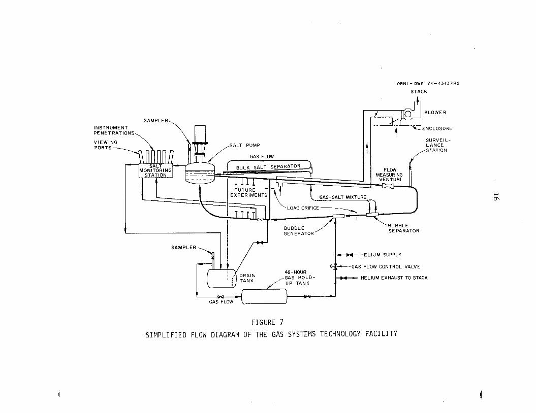
To apprec ia t e t h e importance of t h e gas i n j e c t i o n pressure, an under-
s tanding i s needed o f t h e r e l a t i o n s h i p of t h e bubble genera tor t o o t h e r
po r t ions of a r e a c t o r system. Figure 7 i s a s i m p l i f i e d flow diagram of
t h e GSTF which i s r e p r e s e n t a t i v e of a r e a c t o r system i n regard t o t h e oper-
a t i o n of t h e bubble gene ra to r , The gas i n j e c t e d i n t o t h e fol lowing salt a t
t h e bubble genera tor i s removed by t h e bubble sepa ra to r and i s recyc led
back t o t h e bubble genera tor v i a t h e bulk sa l t s e p a r a t o r , t h e d r a i n t a n k ,
and t h e gas holdup tank.
on e i t h e r end s imula tes t h e de lay t i m e and flow r e s t r i c t i o n of a 48-hr
charcoa l t r a p which i n a r e a c t o r system, would al low r a d i o a c t i v e decay of
t h e Xe-135 concent ra t ion t o an acceptab le l e v e l p r i o r t o r e i n j e c t i o n of
t h e helium sweep gas back i n t o t h e s a l t system.
t o i n j e c t t h e gas i n t o t h e bubble genera tor were s u f f i c i e n t l y below t h e
pump tank (or d r a i n t a n k ) pressure t o provide t h e pressure drops f o r t h e
48-hr charcoa l bed and f o r t h e gas flow c o n t r o l va lve , a compressor f o r
h ighly r a d i o a c t i v e gas would not be requi red . This concept has been shown
t o be f e a s i b l e and t h e necessary design f e a t u r e s have been incorpora ted
i n t o t h e f i n a l GSTF bubble genera tor and system designs f o r cont inued
eva lua t ion wi th hot f u e l sa l t .
The gas holdup tank inc luding t h e t h r o t t l e valves
If t h e pressure r equ i r ed
The measured p res su re d i f f e rences vs gas flow r a t e of t h e f i n a l GSTF
prototype bubble genera tor a r e shown i n Figure 8 f o r a l i q u i d flow ra te of
500 gpm. These pressure d i f f e rences a r e expressed as zero-void l i q u i d head

ORNL-DWG 73-1546
0.050
0.040 - K
9
c! + 0.030
.- - A
>
[r
2 w z w (3 w J m 0.020 m 3 m U
Li (3
0.010
LIQUID FLOW RATE A = 200 gprn
A = 350 gprn = 500 gpm
0 DATA POINT EXCLUDED FROM CALCULATION OF K
O 0 01'
I
0 0.05 0.10 0.15 0.20 0.25 0.30 0.35 0.40 0
FIGURE 6
BUBBLE S I Z E CORRELATION FOR GSTF DESIGN BUBBLE GENERATOR
0.020
0.01 5
N n 0.010 -
0'
. -
0.005
0
O R N L - D W G 74-43137R2
STACK
SAMPLER INSTRUMENT PENETRATIONS,
SALT PUMP VIEW PORT
SEPARATOR
SURVEIL- LANCE
/STAT'oN
MEASURING VENTURI
SAMPLER - HELIUM SUPPLY
48- HOUR GAS HOLD- HELIUM EXHAUST UP TANK
C n r- -
VALVE
TO STACK
FIGURE 7
S I M P L I F I E D FLOW DIAGRAM OF THE GAS SYSTEMS TECHNOLOGY F A C I L I T Y

ORN L-DWG 73-1 545 12
10
8
6
4
2 - -0 3 0-
0
._
.- E O c.’ .I- - W
z W LT
0 -14
-16 L - a a
Q -20
-18 W I
3 U -1 -
-22
- CA LCU LATE D
0 MEASURED -24 -
-26
-28
-30
-32 0 1 2 3 4 5
GAS FLOW RATE (cfm at throat conditions)
FIGURE 8
GAS I N J E C T I O N PRESSLIRE AND OVERALL PRESSURE DROP OF PROTOTYPE BUBBLE GENERATOR AS A FUI4CTION OF GAS FLOW RATE

18
and are re ferenced t o t h e bubble genera tor d i scharge because, i n t h e pro-
posed p ip ing system, t h i s pressure i s more c l o s e l y related t o t h e system
reference pressure i n t h e pump tank gas space. The inc rease i n gas in j ec -
t i o n pressure wi th gas flow r a t e was g r e a t e r t han would be ind ica t ed by
t h e inc rease i n d i f f u s e r l o s s e s and by t h e inc rease i n t h e gas passage
pressure drop.
A s tudy of t h e measured pressure drop d a t a and t h e var ious hydro-
dynamic mechanisms of t h e bubble genera tor i nd ica t ed t h a t t h e p re s su re
d i f f e rences could be descr ibed by s i x terms:
The i n l e t t o t h r o a t head d i f f e r e n c e ,
The mixing l o s s e s and head recovery across t h e sudden enlargement from 2 . 1 i n . t o 2.18 i n .
The mixing l o s s e s and head recovery across t h e 15' d i f f u s e r cone.
The l i q u i d head equiva len t t o the gas compression work between t h r o a t and d ischarge pressure .
H1
H2
H3
H4
H The l i q u i d head equiva len t t o t h e p re s su re drop i n
H6
t h e gas passages.
The l i q u i d head d i f f e r e n c e between t h e l i q u i d and t h e gas plume.
A s a convenience i n comparing d i f f e r e n t f l u i d s , each of t h e above terms
were expressed as f e e t o f zero-void l i q u i d head. With t h e except ions of
H1, which i s dependent only on t h e l i q u i d and of H which i s dependent
only on t h e g a s , t h e pressure d i f f e rences a r e a func t ion of bo th l i q u i d
and gas flow r a t e s , The procedures used i n eva lua t ing t h e s e s i x terms
a r e d iscussed below.
5 '
Figure 9 shows t h e bubble genera tor geometry used f o r t h e fol lowing
a n a l y s i s and t h e l o c a t i o n of t h e var ious p re s su re drops o u t l i n e d above.
The f l u i d heaa, HI, between t h e i n l e t and t h e t h r o a t may be c a l c u l a t e d
from t h e convent ional ven tu r i equat ion:
2

0 R N L-DWG 73- 1 544
THROAT PRESSURE TAP f
GAS CAVITY
‘GAS INJECTION LINE
F I G U R E 9
GEOMETRY OF BUBBLE GENERATOR USED IN A N A L Y S I S OF GAS I N J E C T I O N P R E S S U R E AND OVERALL HEAD LOSS
20
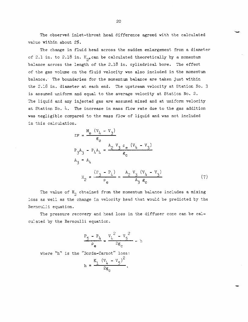
The observed i n l e t - t h r o a t head d i f f e r e n c e agreed wi th t h e ca l cu la t ed
va lue wi th in about 2%.
The change i n f l u i d head across t h e sudden enlargement from a diameter
of 2 . 1 i n . t o 2.18 i n . H ,can be c a l c u l a t e d t h e o r e t i c a l l y by a momentum
balance across t h e l eng th of t h e 2.18 i n . c y l i n d r i c a l bore . The e f f e c t
of t h e gas volume on t h e f l u i d v e l o c i t y was a l s o included i n t h e momentum
balance. The boundaries f o r t h e momentum balance are taken j u s t w i th in
t h e 2.18 i n . diameter a t each end. The upstream v e l o c i t y a t S t a t i o n No. 3
i s assumed uniform and equal t o t h e average v e l o c i t y a t S t a t i o n No. 2 .
The l i q u i d and any i n j e c t e d gas a r e assumed mixed and at uniform v e l o c i t y
a t S t a t i o n No. 4. The inc rease i n mass flow rate due t o t h e gas addi t ion
w a s n e g l i g i b l e compared t o t h e mass flow of l i q u i d and w a s not included
i n t h i s c a l c u l a t i o n .
2
Me (Vb - V 3 ) IF =
QC
A2 v3 P e (v4 - v3) P3A3 - P4A4 - - gC
The va lue of H obtained from t h e momentum balance inc ludes a mixing 2 l o s s as we l l as t h e change i n v e l o c i t y head t h a t would be p red ic t ed by t h e
Bernoul l i equat ion.
The p res su re recovery and head lo s s i n t h e d i f f u s e r cone can be ca l -
cu la t ed by t h e Bernoul l i equat ion.
c c P5 - P4 v4 - v5
'e 2% - h - -
where "h" i s t h e "Borda-Carnot" loss :
21
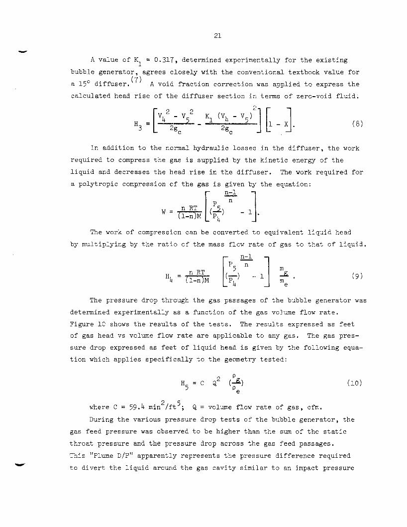
R value of K = 0.317, determined experimental ly f o r t h e e x i s t i n g 1 bubble gene ra to r , agrees c l o s e l y wi th t h e convent ional textbook va lue f o r
a 15' d i f f u s e r . ( 7 ) A void f r a c t i o n co r rec t ion was appl ied t o express t h e
c a l c u l a t e d head r i s e of t h e d i f f u s e r s e c t i o n i n terms of zero-void f l u i d ;
I n add i t ion t o t h e normal hydraul ic l o s s e s i n t h e d i f f u s e r , t h e work
requi red t o compress t h e gas i s suppl ied by t h e k i n e t i c energy of t h e
l i q u i d and decreases t h e head rise i n t h e d i f f u s e r .
a po ly t rop ic compression cf t h e gas i s given by t h e equat ion:
The work r equ i r ed f o r
The work of compression can be converted t o equivalent l i q u i d head
by nwl t ip ly ing by t h e r a t i o of t h e mass flow rate of gas t o t h a t of l i q u i d .
The p res su re drop through t h e gas passages of t h e b
determined experimental ly as a func t ion of t h e gas volume flow r a t e .
Figure 1 0 shows t h e resu1t .s of t h e t e s t s .
of gas head vs volume flow r a t e are app l i cab le t o any gas .
s u r e drop expressed as f e e t of l i q u i d head i s given by t h e fol lowing equa-
t ior i which a p p l i e s s p e c i f i c a l l y t o t h e geometry t e s t e d :
The r e s u l t s expressed as f e e t
The gas pres-
2 5 where C = 59.4 min /f't ; Q = volume flow r a t e of g a s , cfm.
During t h e var ious pressure drop t e s t s of t h e bubble gene ra to r , t h e
gas feed pressure w a s observed t o be h igher than t h e sum of t h e s t a t i c
t h r o a t p re s su re and t h e pressure drop across t h e gas feed passages.
This "Plume D/P" apparent ly r ep resen t s t h e pressure d i f f e rence requi red
t o d i v e r t t h e l i q u i d around t h e gas c a v i t y similar t o an impact pressure

22
ORNL-DWG 73-1543 10,000
5000
2000
1000
500
200
100
50
20
10 0.1 0.2 0.5 1 2 5
GAS FLOWRATE (cfm)
FIGURE 10
PRESSURE DROP OF GAS FEED PASSAGES AS A FUI ICTION OF GAS FLOW RATE
10
23
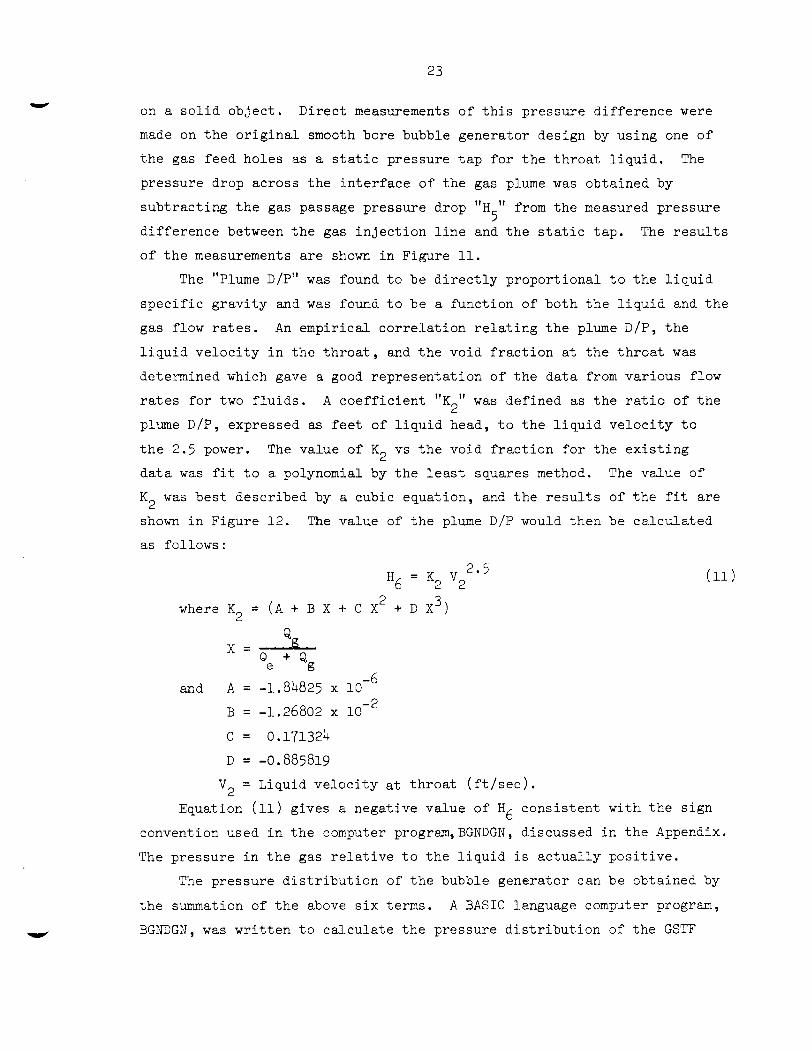
on a s o l i d o b j e c t . Direct; measurements o f t h i s p re s su re d i f f e r e n c e were
made on t h e o r i g i n a l smooth bore bubble genera tor design by us ing one of
t h e gas feed holes as a s t a t i c pressure t a p f o r t h e t h r o a t l i q u i d . The
pressure drop ac ross t h e i n t e r f a c e of t h e gas plume w a s ob ta ined by
s u b t r a c t i n g t h e gas passage pressure drop "H d i f f e r e n c e between t h e gas i n j e c t i o n l i n e and t h e s t a t i c t a p . The r e s u l t s
of t h e measurements a r e shown i n Figure 11.
from t h e measured p res su re 5
The "Plume D/P" was found t o be d i r e c t l y p ropor t iona l t o t h e l i q u i d
s p e c i f i c g r a v i t y and was round t o be a func t ion of bo th t h e l i q u i d and t h e
gas flow r a t e s .
l i q u i d v e l o c i t y i n t h e t h r o a t , and t h e void f r a c t i o n at t h e t h r o a t w a s
determined which gave a good r ep resen ta t ion of t h e d a t a from va r ious flow
rates f o r two f l u i d s . A c o e f f i c i e n t IfK2" w a s def ined as t h e r a t i o of t h e
plume D/P, expressed as f e e t of l i q u i d head, t o t h e l i q u i d v e l o c i t y t o
t h e 2.5 power, The va lue of K vs t h e void f r a c t i o n f o r t h e e x i s t i n g
d a t a w a s f i t t o a polynomial by t h e least squares method. The va lue of
K w a s b e s t descr ibed by a cubic equat ion , and t h e r e s u l t s of t h e f i t a r e
shown i n Figure 1 2 .
as fo l lows:
An empir ica l c o r r e l a t i o n r e l a t i n g t h e plume D/P, t h e
2
2 The value of t h e plume D/l? would then be c a l c u l a t e d
2.5 H = K V 6 2 2
whereK = ( A + B X + C X 2 + D X ) 3 2
x = 0 e + Q g
-6 and A = -1.84825 x 1 0
B = -1.26802 x
C = 0.171324 D = -0.885819
V2 = Liquid velcicity at t h r o a t ( f t / s e c ) ,
Equation (11) gives EL negat ive va lue of H6 cons i s t en t wi th t h e s i g n
convention used i n t h e computer program,BGNDGN, d iscussed i n t h e Appendix.
The p res su re i n t h e gas r e l a t i v e t o t h e l i q u i d i s a c t u a l l y p o s i t i v e .
The pressure d i s t r i b u t i o n of t h e bubble genera tor can be obtained by
t h e summation of t h e above s i x terms. A BASIC language computer progran,
BGNDGN, was w r i t t e n t o c a l c u l a t e t h e pressure d i . s t r i bu t ion of t h e GSTF

24
ORNL-DWG 73-1538
10.0
5.0
2.0 - 0 0 .- - + c L
Q w
I 1.0
5 -I n
0.5
0.2
0.1
0.001 0.02 0.05
0 DEMINERALIZED WATER
0.01 0.2 0.5 0.1
THROAT VOID FRACTION Qd(Qp t Q,)
FIGURE 11
PRESSURE DROP ACROSS THE GAS PLUME INTERFACE AS A FUNCTION OF THROAT V O I D FRACTION
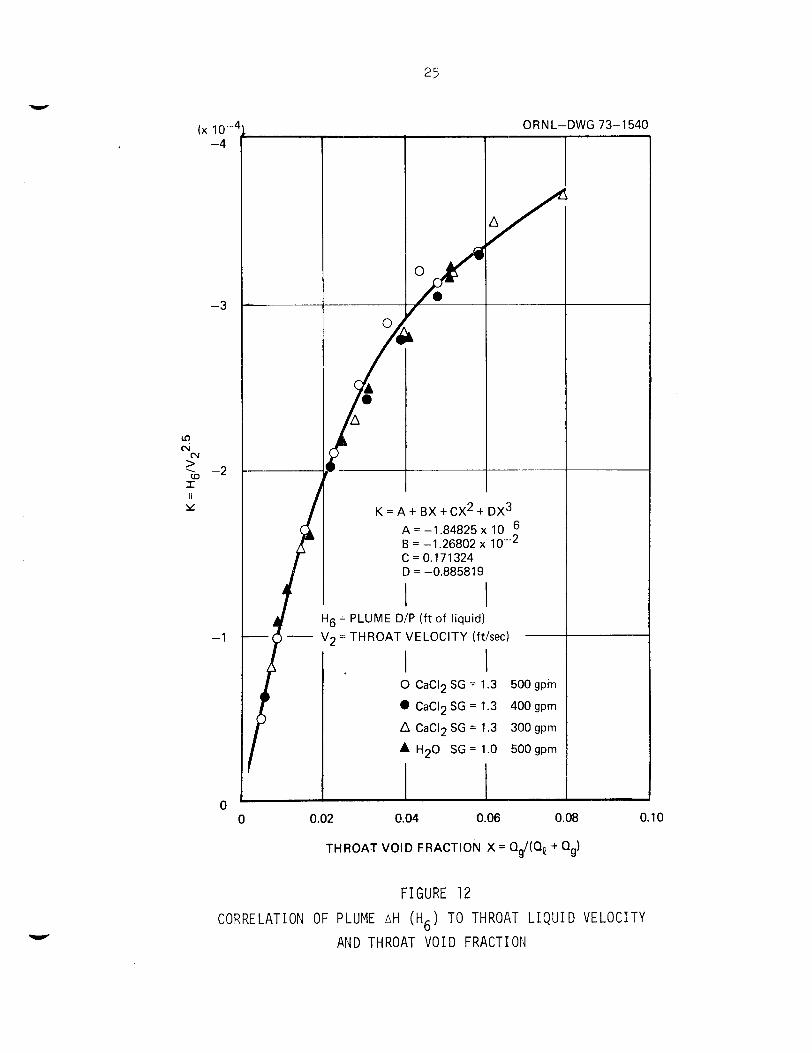
25
(x 10- -4
-3
(v > ' -2 W I ti Y
x
-1
0
-T ORNL-DWG 73-1540
K = A + BX + CX* + D X ~ A = -1.84825 x B = -1.26802 x C = 0.171324 D = -0.88581 9
I I 6 =: PLUME D/P (ft of liquid)
0 CaC12 SG = 1.3
0 CaC12 SG = 1.3
A CaC12 SG = 1.3
500
400
300
A H20 SG = 1.0 500
0 0.02 0.04 0.06 0.08 0.10
THROAT VOID FRACTION X = Qg/(Q, + Qg)
F IGURE 12
CORRELATION OF PLUME AH (ti6) T O THROAT L I Q U I D V E L O C I T Y
AND THROAT V O I D FRACTION
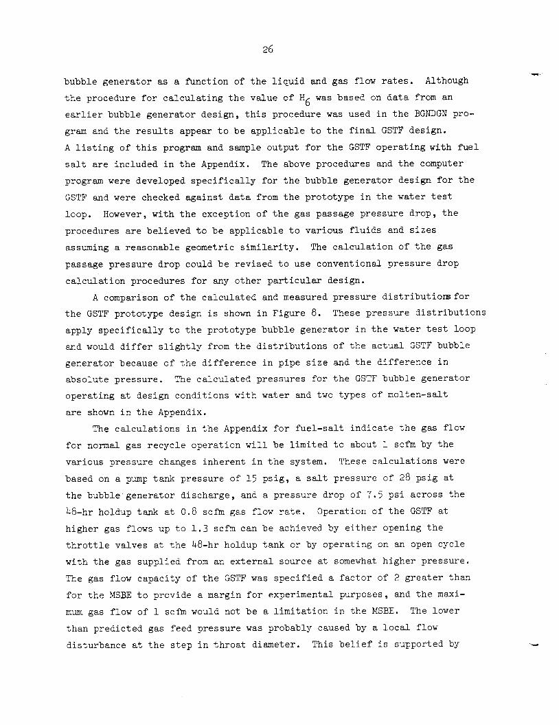
bubble genera tor as a f h c t i o n of t h e l i q u i d and gas flow rates. Although
t h e procedure f o r c a l c u l a t i n g t h e va lue of H6 w a s based on d a t a from an
e a r l i e r bubble genera tor des ign , t h i s procedure was used i n t h e BGNDGN pro-
gram and t h e r e s u l t s appear t o be app l i cab le t o t h e f i n a l GSTF design.
A l i s t i n g of t h i s program and sample output f o r t h e GSTF ope ra t ing wi th f u e l
s a l t are included i n t h e Appendix, The above procedures and t h e computer
program were developed s p e c i f i c a l l y for t h e bubble genera tor design f o r t h e
GSTF and were checked aga ins t d a t a from t h e prototype i n t h e water t e s t
loop.
procedures a r e be l i eved t o be app l i cab le t o var ious f l u i d s and sizes
assuming a reasonable geometric s i m i l a r i t y . The c a l c u l a t i o n of t h e gas
passage p res su re drop could be r ev i sed t o use convent ional pressure drop
c a l c u l a t i o n procedures f o r any o the r p a r t i c u l a r design.
A comparison of t h e ca l cu la t ed and measured p res su re d i s t r i b u t i o r s f o r
However, wi th t h e exception of t h e gas passage p res su re drop, t h e
t h e GSTF prototype design i s shown i n Figure 8. apply s p e c i f i c a l l y t o t h e prototype bubble genera tor i n t h e water t es t loop
and would d i f f e r s l i g h t l y from t h e d i s t r i b u t i o n s of t h e a c t u a l GSTF bubble
ger.erator because of t h e d i f f e r e n c e i n p ipe s i ze and t h e d i f f e r e n c e i n
absolu te pressure .
ope ra t ing a t design condi t ions with water and two types of molten-sal t
a r e shown i n t h e Appendix.
These p re s su re d i s t r i b u t i o n s
The ca l cu la t ed p res su res f o r t h e GSTF bubble genera tor
The c a l c u l a t i o n s i n t h e Appendix f o r f u e l - s a l t i n d i c a t e t h e gas flow
f o r normal gas r ecyc le opera t ion w i l l be l i m i t e d t o about 1 scfm by t h e
var ious pressure changes inherent i n t h e system. These c a l c u l a t i o n s were
based on a pump tank pressure of 15 p s i g , a salt pressure of 28 p s i g a t
t h e bubble genera tor d i scharge , and a pressure drop of 7.5 p s i ac ross t h e
48-hr holdup tank a t 0 .8 scfm gas flow ra te .
h igher gas flows up t o 1 . 3 scfm can be achieved by e i t h e r opening t h e
t h r o t t l e valves a t t h e 48-hr holdup tank or by ope ra t ing on an open cyc le
wi th t h e gas suppl ied from an e x t e r n a l source a t somewhat h igher p re s su re .
The gas flow capac i ty of t h e GSTF w a s s p e c i f i e d a f a c t o r of 2 g r e a t e r than
f o r t h e MSBE t o provide a margin f o r experimental purposes , and t h e m a x i -
mum gas flow of 1 scfm would not be a l i m i t a t i o n i n t h e MSBE.
than p red ic t ed gas feed pressure was probably caused by a l o c a l flow
d is turbance a t t h e s t e p i n t h r o a t diameter .
Operation of t h e GSTF a t
The lower
This b e l i e f i s supported by

t h e f a c t s t h a t t h e measurements of t h e t h r o a t p re s su re j u s t upstream
of t h e s t e p were i n good agreement with t h e ca l cu la t ed va lue of H and
at low gas flow rates t h e o v e r a l l p ressure drop of t h e bubble genera tor
was i n good agreement wi th t h e summation of H
1’
4’ H and H 1’ H2’ 3 The c a l c u l a t e d va lues of H2, H and H4 a r e sub jec t t o some degree 3
of e r r o r because i n an a c t u a l bubble genera tor it i s imprac t i ca l t o pro-
v ide a t h r o a t mixing l eng th long enough t o complete t h e momentum t r a n s f e r
assumed i n t h e c a l c u l a t i o n s . P a r t of t h e mixing l o s s e s ass igned t o t h e
mixing s e c t i o n occur i n t h e diff’user and could account f o r t h e d i f f e r e n c e s
i n s lope between t h e ca l cu la t ed and measured pressures shown on Figure 8.
I V . C O N C L U S I O N S AND RECOMMElNDATIONS
The bubble genera tor design developed f o r app l i ca t ion i n t h e Gas
Systems Technology F a c i l i t y and t h e Molten-Salt Breeder Experiment i s
expected t o success fu l ly meet t h e c r i t e r i a s p e c i f i e d i n Table I.
The gas flow l i m i t a t about 1 scfm would be a va luable s a f e t y
f e a t u r e i n t h e event of a malfunction of t h e gas flow c o n t r o l system a t t h e
maximum flow p o s i t i o n . However, an i n i t i a l t r a n s i e n t a t a h igher flow
could occur depending on t h e l o c a t i o n and s i z e of holdup volumes and pres-
s u r e drops i n t h e gas sys t en . The design of a r e a c t o r gas-system should
attempt t o minimize t h e r a t e and du ra t ion of t h i s t r a n s i e n t .
There are u n c e r t a i n t i e s i n regard t o t h e mechanism of bubble formation
i n t h e bubble genera tor and a r e l a t i v e l y ex tens ive program would be r equ i r ed
t o fully eva lua te t h e proposed mechanisms. H o w e v e r , t h e bubble s i z e pro-
duced by t h e bubble genera tor i s be l ieved t o have a minor inf luence on t h e
o v e r a l l opera t ion of a r e a c t o r c i r c u l a t i n g system because of t h e bubble
deg rad ia t ion and compression i n pass ing through t h e pump and t h e o t h e r
changes i n s i z e t h a t may occur because of coalescence, gas s o l u b i l i t y ,
and p res su re changes.
mechanisms of bubble formation does not appear t o be j u s t i f i e d a t t h i s
t i m e . However, p lans have been made t o check t h e v i s c o s i t y dependence of
t h e recommended c o r r e l a t i o n .
Therefore , an e f f o r t t o f u l l y eva lua te t h e proposed
The c a l c u l a t i o n procedures and computer program developed f o r e s t i -
mating t h e p re s su re d i s t r i b u t i o n as a func t ion o f l i q u i d and gas flow
r a t e s appears t o be s u f f i c i e n t l y accu ra t e f o r most a p p l i c a t i o n s . The
s u i t a b i l i t y of t h e s e design c a l c u l a t i o n s t o cover ope ra t ion i n a high
28
temperat,ure sa l t system w i l l be eva lua ted from t h e ope ra t ing data of t h e
GSTF
The c a l c u l a t i o n procedures f o r var ious p re s su res and bubble diameter
a r e be l i eved t o be app l i cab le t o o t h e r s i z e s , bu t w e have no experimental
v e r i f i c a t i o n of t h i s . The reduced s c a l e tes ts completed e a r l y i n t h e pro-
g r m were survey type experiments and i n s u f f i c i e n t d a t a were taken t o
eva lua te s c a l e e f f e c t s , Therefore any bubble genera tor of s i g n i f i c a n t l y
d i f f e r e n t s i z e or geometry should be checked experimental ly aga ins t t h e
c a l c u l a t i o n s p r i o r t o u s e i n any c r i t i c a l app l i ca t ion .
V. ACKNOWLEDGEMENT
The author i s indebted t o many ind iv idua l s f o r t h e i r cooperat ion and
a s s i s t a n c e i n completing t h i s work.
T . S. Kress i n sugges t ing mechanisms f o r t h e bubble s i z e c o r r e l a t i o n and
t h e con t r ibu t ion of G . M . Winn f o r t h i s opera t ion o f t h e t e s t loop and
h i s execut ion of t h e va r ious experiments a r e g r a t e f u l l y acknowledged.
I n p a r t i c u l a r , t h e c o n t r i b u t i o n of

NOMENCLATURE
5 - A5 D1 - D
5 F a
M
'Re
5 P3 - P
Qe, Qg
R
T
5 v1 - v
X
d
QC
Me'
n
6
E
'e "g
'ey'g
0
Cross s e c t i o n a l a r eas Of bubble genera tor (see Fig. 9 ) ( f t ' )
Diameters clf bubble genera tor ( s e e F ig . 9 ) ( ft )
Approach area f a c t o r [1-(A2/A1) ] 2 -1/2
Thermal expansion f a c t o r [l + a(T-530) 1 2
Various d i f f e r e n t i a . 1 heads a s soc ia t ed wi th bubble genera tor ( s e e F ig . 9 ) ( f t of zero void l i q u i d )
Molecular weight of gas
Reynolds number, VDp/p
S t a t i c p re s su res i n bubble genera tor ( s e e F ig . g ) ( l b f / f t 2 )
Volume flow rate o f l i q u i d o r gas ( f t 3 / s e c )
Universal gas cons tan t 1545.3 f t / l b f / # mole-OR
Temperature , O R
V e l o c i t i e s i n bubble genera tor ( see Fig . 9 ) ( f t / sec
Void f r a c t i o n
Veloc i ty c o e f f i c i e n t assumed = 1 . 0
Bubble diameter ( f t )
Volume averaged bubble diameter ( f t )
Grav i t a t iona l conversion f a c t or ( lbm-f t / lbf-s ec2 )
Mass flow r a t e of l i q u i d or gas ( lbm/sec)
Poly t ropic gas compression cons tan t
Coef f i c i en t of thermal expansion per OF = 8 x 10 -6
Gas f i l m t h i ckness ( f t )
Power d i s s i p a t i o n per u n i t volume ( f t - l b /f't 3 - s e e ) f
Vi scos i ty of l i q u i d or gas ( l & / f t - s e c )
Densi ty of l i q u i d o r gas ( l&/ f t3 )
Surface t e n s i o n ( l b f / f t )
30
REFERENCES
(1) M. W. Rosenthal , P. N . Haubenreich, and R . B. Briggs, The Develop- ment S t a t u s of Molten-Salt Breeder Reactors , ORNL-4812 , August 1972, pp 274-297.
( 2 ) J. R . McWherter, Molten S a l t Breeder Experiment Design Bases , ORNL-TM-3177, November 1970.
( 3 ) R . H. Guymon, System Design Descr ip t ion of t h e Gas Systems Technology F a c i l i t y , ORNL-CF-72-3-1, March 30, 1972.
(4) MSR Program Semiannual Progress Report Feb. 28, 1969 , ORNL-4396 , p 95.
( 5 ) J . 0. Hinze, Fundamentals of t h e Hydrodynamic Mechanism of S p l i t t i n g i n Dispersion Processes , AIChE Journa l , Vol. 1, No. 3 , 1955, p 295- 298.
( 6 ) T . S. Kress , Mass Transfer Between Small Bubbles and Liquids i n Cocurrent Turbulent P i p e l i n e Flow, ORNL-TM-3718, A p r i l 1972, p 58.
( 7 ) J . K . Vernard, Elementary F l u i d Mechanics, John Wiley and Sons, 1947, P 176.
31
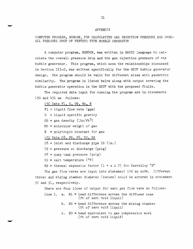
APPENDIX
COMPUTER PROGRAM, BGNDGN,, FOR CALCULATING GAS INJECTION PRESSURE AND OVER- ALL PRESSURE DROP OF VENTURI TYPE BUBBLE GENERATOR
A computer program, BGNDGN, w a s w r i t t e n i n BASIC language t o ca l -
c u l a t e t h e o v e r a l l p re s su re drop and t h e gas i n j e c t i o n pressure of t h e
bubble gene ra to r , This program, which uses t h e r e l a t i o n s h i p s d iscussed
i n Sec t ion 111-2, was w r i t t e n s p e c i f i c a l l y foi- t h e GSTF bubble genera tor
des ign , The program should be v a l i d f o r d i f f e r e n t s i z e s with geometric
s i m i l a r i t y . The program i s l i s t e d below along with output covering t h e
bubble genera tor ope ra t ion i n t h e GSTF wi th t h e proposed f l u i d s .
The requi red d a t a input f o r running t h e program a r e i n s ta tements
450 and 451 as fol lows:
450 Data F1, G , G 9 , Mo, N
F1 = l i q u i d flow rate (gpm)
G = l i q u i d s p e c i f i c g r a v i t y
G 9 = gas d e n s i t y (1t1s/ft3)
1\10 = molecular weight o f gas
N = po ly t rop ic cons tan t f o r gas
451 Data D 8 , P9, P8, T2, K 9 D 8 = i n l e t and d ischarge p ipe I D ( i n . )
D 9 = pres su re a t d i scharge ( p s i g )
P8 = pump tank pressure ( p s i g )
T 2 = sa l t temperature ( O F )
K 9 = thermal expansion f a c t o r (1 + CI 0 T ) f o r Has te l loy "N" The gas flow r a t e s a r e input i n t o s ta tement lh0 as scfm. Di f f e ren t
t h r o a t and mixing chamber diameter ( i n c h e s ) could be en te red i n s ta tement
30 and 31, r e spec t ive ly .
There a r e four l i n e s of output f o r each gas flow rate as fol lows:
Line 1. a. H1 = l e a d d i f f e r e n c e across t h e d i f f u s e r cone ( f t of zero void l i q u i d )
( f t o f zero void l i q u i d )
( f t of zero void l i q u i d )
b . H 2 = head d i f f e r e n c e ac ross t h e mixing chamber
c . H 3 = head equiva len t t o gas compressicn work

32
d . H 4 = t o t a l head d i f f e r e n c e between t h e gas i n j e c t i o n l i n e and t h e sa l t a t t h r o a t ( f t of zero void l i q u i d ) .
( f t of zero void l i q u i d ) . e . H 5 = head d i f f e r e n c e across t h e t h e gas passages
Line 2. a . The gas flow ra te (scfm) .
temperature ) . b . The gas flow ra te (cfm a t t h r o a t pressure and
c . The salt s t a t i c p re s su re a t t h e t h r o a t ( p s i g ) .
d . The s t a t i c pressure a t t h e gas i n j e c t i o n l i n e ( p s i g ) .
a. The p res su re i n t h e GSTF gas l i n e 210 upstream of t h e flow c o n t r o l va lve ( p s i g ) .
b . The p res su re drop across t h e GSTF gas flow con t ro l va lve ( p s i g ) .
a . The o v e r a l l head lo s s of t h e bubble genera tor ( f t of zero void l i q u i d ) .
b. The head d i f f e r e n c e between bubble genera tor d i s - charge and t h e gas i n j e c t i o n l i n e ( f t of zero void l i q u i d ) .
Line 3.
Line 4.
A nega t ive va lue of t h e va lue D/P i n output l i n e 3 i n d i c a t e s t h e
p re s su re drop a v a i l a b l e i n t h e GSTF gas-system i s i n s u f f i c i e n t t o provide
r ecyc le ope ra t ion a t t h a t flow r a t e and a t t h e design flow r e s t r i c t i o n
of t h e 48-hr holdup t ank . This c a l c u l a t i o n assumes a 7 .5 p s i p ressure
drop across t h e 48-hr holdup tank a t 0 .8 scfm and t h a t t h e pressure
drop v a r i e s wi th t h e square of t h e volume flow rate .

33
1 REM PGNDGN CHG 6/8/72 CALC RlJPRLE GElV PRESS DIST 9 READ A ~ D A ~ D A ~ D A ~ 10 READ FlrG1G9rM00N 20 READ D ~ D P ~ D P8 m T ~ D K9 21 H 1 = 0 22 H2=0 23 H3=0 30 D9=2.10 31 D1=2.18 45 POz14.7 50 PRINT "LIQ SG=@'Gr"MBL WT="MOD"DIS PKESS="P9 6 0 PR IN T "L I Q FL@W="F 1 0 "THR D I A="D9 D "ROR E D I A = " D 1 61 D2=D8/12 62 D=D1/12 6 3 DO=D9/12
80 T=T2+460 90 Kl=N/< I-N)
70 P2=P9+ 14.7
100 110 120 130 131 I32 140 150 160 161 170 180 190 200 210 220 230 240 2 49 2 50 2 60 261 270 28 0 29 0 300 310 320 32 1 322 323 3 32 340 3 60 370 38 0 38 1 38 2 38 3 399 400 40 1 402 403 404 4 05 450 45 1 500
K2=(N-l)/N QO= F 1 / C 7 48 * 60) M 1 = QO*G*62 4 VO= (301 ( 0.78 5 * ( DO*K9 ) t P ) V=QO/( 0.785*( D2*K9) t2) H= (VOt2-Vt 2) /64.4 F0R F?=O T0 1.41 STEP e 2 M 2 = F2*G9/ 60 z=o PO=P2-(Hl+H2tH3)*62.4*G/l44 Ql=QO+FP*T/493* 14.7/( P0*60) Q2=QO+F2*T/493*14.7/(P2*60) Vl=Q1/(0.785*(D*K9)t2) V2=Q2/< 0.785*( D2*K9 ) t 2) F9=FP* 14 7/PO*T/( 49 3* 6 0 ) X2= F9 1 ( QO+ F9 1
G l=G*QO/Ql H I=((Vlt2-V2t2)/64.4-0.317/64.4*(Vl-V2) t2)*< 1 . O - X 2 )
F3=F2*T/493*14*7/PO H 2 = - V l * G P * ( V l - V 0 ) ~ ( 3 2 . 2 * G ) - F 3 * 0 . 4 1 h 7 PO=P2-(Hl+H2+H3) *62.4*G/ 144 IF P O C O THEN 404 W = K 1*1545*T/IYO*< <P2/PO) tK2- 1 0 ) H 3= W*M2/M 1 PO=P2-(Hl+H2tH3)*62.4*~/144 F3=F2*T/493* 14*7/PO Gg=G9*493/T*PO/ 14.7 H 5=- 59 488 *F3 t 2*G8 / ( G* h? 4) X3= F3/( F1/7 48+F3) K3=A 1 +A2*X3+63*X3?2+A4*X 3t 3 H4=K3*VOt ?.50+H5 P3=P0-14.7 PO=P2-(Hl+H2+H3+H4)*62*4*G/144 z=z+ 1 IF Z<3 THEN 170 P7=P8-9 5 8 * < F2+0.0847 6) t2 P6= P7- (PO- 1 4- 7 1 Ll=Hl+H2+H3+Y4 L=H-(Hl+HP+H3) PRINT PRINT H 1 0 H2, H 3 > H ~ D H S P R I N T " S C F M = " F ~ J " T C F ~ * I = " F ~ D " T PR="P3,"G PR="PO- 14.7 PRI NT"L 2 I O PR="P7 D "VALVE D/P="P6 PRINT "1-0 D/H="LD"Q-G D/H="Ll NEXT F? DATA DATPi DATA 5.047~280 15, 13000 1.009 END
- 1 R 48?5E-61- 1 -268 O2E-?, 0.17 13340 -0.68 5H 19 500~3.2836~ 0.01 1204,l 67

34
Table A-1
GSTF Bubble Generator Operation on Fuel-Sal t and H e l i u m
L I Q SG= 302836 N Q L WT= 4 DIS PRESS= 28 LIQ FL0W= 500 THR D I A = 2 0 1 R0RE DIA= 2.18
20.9288 4.30198 0 - 2 5F1365E-2 0 SCFM= 0 TCFM= 0 T PP=-7090077 G PR=-7.86401 L 210 PR= 14.9312 V P L V E D/P= ?3*79!52 1-0 D/H= 5.97787 0-G D / H = 25.205
21 1968 3.20759 -0*256411 -2.5625 -4elH451E-4 SCFM= 0.2 TCFM= 1.35849 T PR=-6*36006 G PR=-2.7139 L 210 PR= 14.2232 V A L V E DIP= 1609.771 1-0 D/H= 7006068 0-G D/H= 21.5555
-3.67663 -2.90790F-3 21.3703 2050307 -0.462839 SCFM= 0.4 TCFM= 2.23567 T PR=-5.31064 G PR=-7.91799E-7 L 210 PR= 12.7488 V A L V E DIP= 12.828 1-0 D/H= 7.7982 O-G D/H= 19.7339
31 5243 1.5788 -0.637301 -4 23783 - 5 9 603HE-3 SCFM= 0.6 TCFM= 3.05499 T PR=-4.39319 G PR= 1.63686 L 210 PR= 10.508 V A L V E DIP= 8.87111 1-0 D/H= 8.44298 0-G D/H= 38.5278
21 6677 1.29773 -0.787922 -4.55608 -9.K0036E-3 SCFM= 0.8 TCFM= 3.76738 T PR=-3.556? G PR= ?.9266=! L 210 PR= 7.50077 V A L V E DIP= 4.57415 1-0 D/H= 9.03121 Q-G D / H = 17.6214
31 .YO? 0.754595 -0.920421 -4.77094 - 1 43230E-2 SCFM= 1 TCFM= 4.40476 T PH=-2.7859 G PR= 4.00364 L 210 PR= 3072717 V A L V E D/P=-0.275467 1-0 D/H= 9.57257 0-G D/H= 16ei36'52
21 09267 0*'250605 - 1 039 16 -4.95226 - 1 9 467 4E-2 SCFM= 1.2 TCFM= Oe9F9OP T t'K=-3*07739 G PI?= 4.96915 L 310 PR=-0*813837 V A L V E D/P=-5.78 198 1-0 D/H= 10.0705 Q - G D/H= 16 .1859
22.0416 - n 3 1 334 -1.14751 -5.13R5H -2.53009E-? SCFM= 1.4 TCFM= 5.53574 T PR=-1.42803 0 PR= 5.88363 L 310 PR=-6*11923 V A L L E D/P=-12*0028 1-0 D/H= 10.5269 0-G D/H= 15.5432

35
Table A-2
GSTF Bubble Generator Operation on Flush S a l t (66-34 Mole % LiF-BeFp) ar,d H e l i u m
LIQ SG= 1.942 MOL WT= 4 DIS PRESS= 22.69 LIQ FL0W= 500 THR DIA= 2 . 1 P0HE DIA= 2.18
20 9 288 4.30 198 0 - 2 0 5 8 3 6 5 E - 2 0 SCFM= 0 TCFM= 0 T PR= 1.45742 G PR= 1.47916 L 210 PR= 14.9312 VALVE DIP= 130452 1-0 D/H= 5.97787 0-G D/H= 25.205
21 108 3057596 -0.177838 - N 47477 - 6*88325E-4 SCFM= 0.2 TCFM= 006P5965 T PR= 2.0673 G PR= 3.30837 L 210 PR= 14.2738 VALVE DIP= 10.9148 1-0 D/H= 6.7026 O-G D/H= 23*031:3
21 02619 2.9538 1 -0.339 626 -2.4979 -2.66891E-3 SCFM= 0.4 TCFM= 1.211356 T PR= 2.59748 G PR= 4.69954 L 210 PR= 12.7485 VALVE DIP= 8.04923 1-0 D/H= 7.33261 0-G D/H= 21.3782
21 4023 2.3572-4 -0.488344 - :3 2 2 3 9 6 -5 8 4 167E-3 SCFM= 0.6 TCFM= 1.77081 T PI?= 3.08124 G PR= 5.79431 L 210 PR= 10*508 VALVE DIP= 4.71:367 1-0 D/H= 7.90747 0-G D/H= 20*077:3
21 e5347 1.85413 - 0 . 6?S723 -:3.73996. - 1.01273E-2 SCFM= 0.8 TCFM= 2.30244 T PR= 3.53413 G PR= 6.68143 L 210 PR= 7.50077 VALVE DIP= 0.819344 1-8 D/H= 8.44564 0-G D/H= 19.@?31
21.6615 1.34347 -0.752975 -4- 10849 - 1.5459TE-P SCFM= 1 TCFM= 2.8'1173 T PR= 3.96418 G PR= 7.4216'2 L 210 PR= 3.72717 VALVE D/P=-3*69 4b5 1-0 D/H= 8,95668 8-G D/H= 18.14315
21 07843 0.8 497 62 -0.871 064 -4.376 - 2 - 17H 1 OF-2 SCFM= 1 - 2 TCFM= 3.30129 T PR= 4037573 G PI?= 8.051377 L 310 PP=-O.R1?827 V A L V E D I P z - 8 87 I 1 1-0 D/H= 9.44572 Q-G D/H= 17.387
21 -9036 0.370441 - 0 9 8 08 26 - 4.5775 - 3 9 0444E-3 SCFM= 1.4 TCFM= 3.7'133 T PI?= 4.77109 G PR= 8.6232 L 210 PP=-6.11923 VA L V E D/P=-IA.7434 1-0 D/H= 9.91553 Q-G D/H= 16.7157

36
Table A-3
GSTF Bubble Generator Operation on Water and Helium
LIO SG= 1 MBL FT= 4 D I S PRESS= 18.959 L I Q FL( IU= 500 T H R D I A = 2.1 R Q R E D I A = 2-18
21 a6925 4.45896 0 -2.70202E-3 0 S C F M = 0 T C F M = 0 T PR= 7.6267 G PR= 7.63841 L 210 PR= 14.9312 V A L V E DIP= 7029277 1-8 D / H = 6.196 0-G D/H= 26.1245
21 -9089 3.5913n -0.23437 1 - 1.69285 -7 43097E-3 S C F M = 1 T C F M = 0.695957 T PR= 8.0078 G PR= 8.74077 L 210 PR= 3.72717 VALVE: D/P=-S*0136 I - B D / H = 7.07409 0-G D / H = 2305805
33.1104 2.79977 -0.449001 -2 87493 -3.92703E-3 S C F M = 2 T C F M = 1.37067 T PR= 8.35917 G PR= 9*6049R L 310 PR=-26.6368 V A L \/E D/ P= - 3 6 2 4 1 8 1-0 Din= 7.88634 0-G D/H= 21 5862
22 3024 2.03906 - 0 . 6 4 6 1 5 - 3 7 08 27 - 6 - 49235E-2 S C F M = 3 T C F M = 2.05'653 T PR= 8.69104 G PR= 10.398 L 210 PH=-76*1608 V A L V E D / P = - 8 6 * 4588 1-0 D/H= 8.65218 O-G D / H = 1Y e987
22 e 488 1 30439 -0.82741 3 - 4.297 3 -0.11 3879 S C F M = 4 T C F M = 2.66637 T PR= 9.00751 G PR= 10.8697 L 210 PR=-144.845 V A L V E D/P=-l55* 7 15 1-0 D/H= 9.3825 3 - G D / H = 18.6677
22.6688 0.589443 -0.9Y40C.4 -4.7?431 -0.175685 S C F M = 5 TC.FK= 3.29051 T PR= 9.311? Ci PR= 11.3584 L 210 PP=-232.689 V A L V E D/P=-244.047 1-0 D / H = 1@*0833 0 - G D / Y = 17.5399
22 .8 454 -0.1 OS 465 - 1.14722 - 5 . 0 5 4 7 1 - 0.2 499 44 S C F M = 6 T C F M = 3*9@1h'3 T PH= 9.60347 G PP= 11.7938 L 320 PR=-339.691 V A L V E D/P=-351*4H7 1-0 D / H = 10.7575 (3 -G D/H= 16.535

INTERNAL D I STRI €31 JTT ON
1. 2 . 3. ]I. . 5. 6. 7. 8. 9 . 10.
11. -12. 13. 1 4 . 1 5 . 16. 17. 18 * 19. 20. 21. 22. 23.
24.-25. 26. 27. 28. 39. 30. 31. 32.
33.-34. 35.
36. -38 * 39.
S. E . Beall 31. Render C . E. B e t t i s E. S . Be t t i s R . B. Briggs C . J . Claffey C . W . Col l ins W. B. C o t t r e l l D . E. Ferguson A. P. Fraas C . H . Gabbard A. G . G r i n d e l l P. N . Haubenreich H . W. Hoffknan P . R . Kasten M. I . Lundin R . N . Lyon H. G . XacPherson R . E. XacPherson H . C . McCurdy A . J . Miller A. T4. Perry ?.1. W. Rosenthal Dunlap Sco t t M . Sheldon M . J . Skinner I . SDiewak D. A. Sundbere: D . B. Trauger G . D . Wnitman Cent ra l Res. Likrary Document Ref. Sect ion Labor at ory Records Laboratory Records (LFD-RC)
EXTERNAL DISTRIBUTION
40. bl. Shaw, AEC-Wash. 4 1 . -42. 11. Haberman, AEC-Wash.
43. D . F. Cope, AEC-OS? 44. David E l i a s , AEC-Wash . 45. J . E . Fox, AEC-Wash. 46. E. C . Kovacic, AEC-Wash.
47.-49. D i r e c t o r , Divis ion of Reactor Licensing, AEC-Wash. 50.-51. D i r e c t o r , Divis ion o f Reactor Standards, AX-Wash. 52.-68. Manager, Technical Information Center , AEC-rT2r k i , ' s ? :vlen: e r t
70 .-71. 69. Research and Technical Support Div is ion , U C , 036
Technical Information Cer?ter, AEC
V