venture - mt ortho · the venture™ anterior cervical plate system features integrated locking...
TRANSCRIPT

VENTURE™
Anterior Cervical Plate System Surgical Techniqueas described by:
Regis Haid, MDAtlanta Brain and Spine CareAtlanta, Georgia
Iain Kalfas, MDCleveland Clinic FoundationCleveland, Ohio
Steve Papadopoulos, MDBarrow Neurological InstitutePhoenix, Arizona
Rick Sasso, MDIndiana Spine GroupIndianapolis, Indiana
Volker K. Sonntag, MDBarrow Neurological InstitutePhoenix, Arizona
Vincent Traynelis, MDUniversity of Iowa HospitalIowa City, Iowa


��
The VENTURE™ Anterior Cervical Plate System features Integrated Locking Technology — an automatic locking mechanism incorporated into the plate design. Once engaged, this locking device physically blocks screw backout and allows visual verification that the locking mechanism has engaged and the screws are locked.
Visual Lock Verification
Midline Alignment
Notch
Fixed, Variable, or Hybrid Screw Constructs with Self-Tapping or
Self-Drilling Screws
Low Profile
Integrated Locking
Technology
Hex Style Stab and Grab Screw Design
Graft Visualization
PRoDucT FeaTuReSPRoDucT FeaTuReS

��
Preparation/Plate Contouring 3
Plate Placement/Fixation 4
Screw Options 5
Fixed Angle Drill Guide Method 6
Variable Angle Drill Guide Method 7
Drill/Tap/Screw (DTS) Guide Method 8
Locking Mechanism �0
Revision/Explantation ��
Product Ordering Information ��
VENTURE™
Anterior Cervical Plate System Surgical Technique
conTenTSconTenTS

33INTEGRATED LOCKING™ TECHNOLOGY
To ensure ideal anatomical fit, the VENTURE™ plate is pre-machined with lordosis. If increased or decreased lordosis is desired, the plates can be further contoured with the Plate Bender [ FIGURE � ].
A right- or left-sided surgical approach may be used as determined by surgeon preference. Standard anterior exposure techniques should be utilized to expose the spinal segment(s) to be fused. Care should be exercised to ensure complete decompression of neural elements and the removal of any anterior osteophytes. The plate length will be determined by the number of levels to be fused. A properly-sized plate should span the distance between the caudal and cephalad vertebrae [ FIGURE � ].
Figure �
PlaTe conTouRInG
Figure �
Increase Decrease
To increase lordosis, the anterior face of the plate must be facing up.
To decrease lordosis, the posterior face of the plate must be facing up.
PRePaRaT IonPRePaRaT Ion
PlaTe conTouRInG
44 VENTURE™ ANTERIOR CERVICAL PLATE SYSTEM
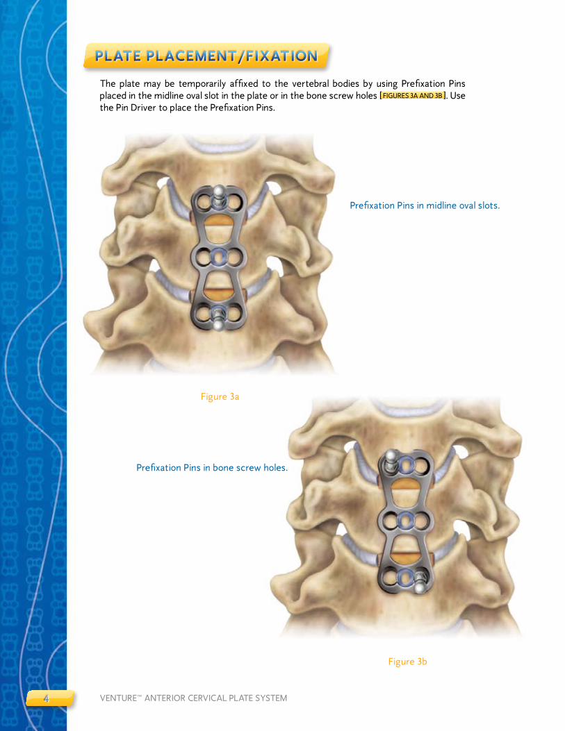
The plate may be temporarily affixed to the vertebral bodies by using Prefixation Pins placed in the midline oval slot in the plate or in the bone screw holes [ FIGURES 3A AND 3B ]. Use the Pin Driver to place the Prefixation Pins.
Figure 3a
Figure 3b
PlaTe PlaceMenT/FIXaT Ion
Prefixation Pins in bone screw holes.
PlaTe PlaceMenT/FIXaT Ion
Prefixation Pins in midline oval slots.
55INTEGRATED LOCKING™ TECHNOLOGY
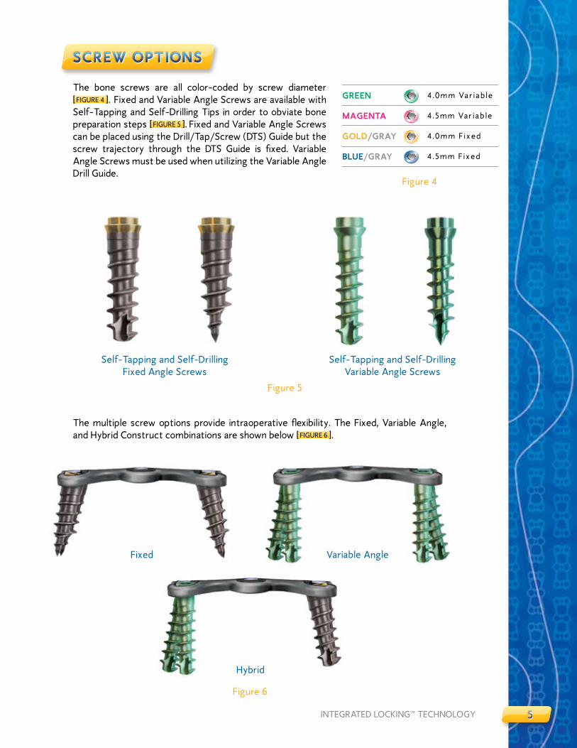
The bone screws are all color-coded by screw diameter [ FIGURE 4 ]. Fixed and Variable Angle Screws are available with Self-Tapping and Self-Drilling Tips in order to obviate bone preparation steps [ FIGURE 5 ]. Fixed and Variable Angle Screws can be placed using the Drill/Tap/Screw (DTS) Guide but the screw trajectory through the DTS Guide is fixed. Variable Angle Screws must be used when utilizing the Variable Angle Drill Guide.
Figure 5
Self-Tapping and Self-Drilling Fixed Angle Screws
Self-Tapping and Self-Drilling Variable Angle Screws
Figure 6
Fixed Variable Angle
Hybrid
ScRew oPT IonS
The multiple screw options provide intraoperative flexibility. The Fixed, Variable Angle, and Hybrid Construct combinations are shown below [ FIGURE 6 ].
Figure 4
GReen 4.0mm Var iab le
MaGenTa 4.5mm Var iab le
GolD/GRaY 4.0mm F ixed
Blue/GRaY 4.5mm F ixed
ScRew oPT IonS

66 VENTURE™ ANTERIOR CERVICAL PLATE SYSTEM
Figure 7
Figure 8b
After the pilot hole is prepared, load a Fixed Angle Screw onto the screwdriver by placing the screwdriver tip directly into the selected screw head. The fixed angles are �0 degrees either cephalad/caudal and six degrees medial [ FIGURES 8A AND 8B ]. Tighten the screw until it passes beyond the locking mechanism and is securely seated in the plate.
FIXeD anGle DRIll GuIDe MeTHoD
Figure 8a
For intraoperative efficiency the Fixed Angle Drill Guide is color-coded with blue and gold bands to correspond with the Fixed Angle Screw color scheme. Place the Fixed Angle Drill Guide into the desired bone screw hole of the plate. Insure that the drill guide is securely seated into the bone screw hole. Pass a drill bit through the drill guide and rotate clockwise until the drill bit has reached the depth of ��mm designated by the depth control rim on the drill bit shaft [ FIGURE 7 ].
Color-coded
FIXeD anGle DRIll GuIDe MeTHoD
77INTEGRATED LOCKING™ TECHNOLOGY
Figure �0a
VaRIaBle anGle DRIll GuIDe MeTHoD
- -
Figure �0b
Figure 9
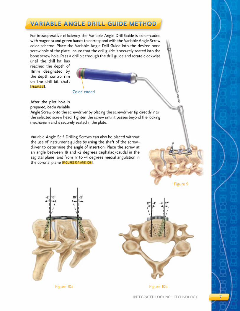
For intraoperative efficiency the Variable Angle Drill Guide is color-coded with magenta and green bands to correspond with the Variable Angle Screw color scheme. Place the Variable Angle Drill Guide into the desired bone screw hole of the plate. Insure that the drill guide is securely seated into the bone screw hole. Pass a drill bit through the drill guide and rotate clockwise until the drill bit has reached the depth of ��mm designated by the depth control rim on the drill bit shaft [ FIGURE 9 ].
After the pilot hole is prepared, load a Variable Angle Screw onto the screwdriver by placing the screwdriver tip directly into the selected screw head. Tighten the screw until it passes beyond the locking mechanism and is securely seated in the plate.
Variable Angle Self-Drilling Screws can also be placed without the use of instrument guides by using the shaft of the screw-driver to determine the angle of insertion. Place the screw at an angle between �8 and -� degrees cephalad/caudal in the sagittal plane and from �7 to -4 degrees medial angulation in the coronal plane [ FIGURES �0A AND �0B ].
VaRIaBle anGle DRIll GuIDe MeTHoD
Color-coded

88 VENTURE™ ANTERIOR CERVICAL PLATE SYSTEM
When using the Drill/Tap/Screw (DTS) Guide press the button on the guide and insert the tip into the midline oval slot [ FIGURES ��A AND ��B ]. Release the button to secure the DTS guide to the plate. Next, position the plate on the vertebral body.
DRIll/TaP/ScRew (DTS) GuIDe MeTHoD
Figure ��a
Figure ��b
Button
DRIll/TaP/ScRew (DTS) GuIDe MeTHoD

99INTEGRATED LOCKING™ TECHNOLOGY
Figure �3b
Figure ��
Figure �3a
DRIll/TaP/ScRew (DTS) GuIDe MeTHoD Cont inuedDRIll/TaP/ScRew (DTS) GuIDe MeTHoD
Use an awl to create a pilot hole for Self-Drilling Screws, or pass the drill bit through the tube to create a pilot hole for Self-Tapping Screws [ FIGURE �� ] [Note: Some surgeons may elect to forego pilot hole preparation with Self-Drilling Screws]. The DTS Guide insures a �0 degree cephalad or caudal angle and a 6 degree medially-convergent angle on the superior and inferior ends of the plate. The DTS Guide will insure 0 degree cephalad/caudal angles and 6 degree medially convergent angles at segmental levels. For drilling and placement of subsequent screws, the innovative design of the DTS Guide allows the guide tube to be moved to the adjacent bone screw hole by lifting the guide tube slightly and rotating the guide tube �80 degrees. The guide tube will lock in the proper position when released [ FIGURES �3A AND �3B ].

�0�0 VENTURE™ ANTERIOR CERVICAL PLATE SYSTEM
Initial Screw Insertion
Figure �4a
Deflection of Locking Ring
Figure �4b
Locked Position
Figure �4c
locKInG MecHanISMlocKInG MecHanISM
The Integrated Locking Technology used in the development of the VENTURE™ Anterior Cervical Plate System allows for the use of Variable Angle Screws, Fixed Angle Screws, or a combination of both with either Self-Tapping or Self-Drilling tips. As the screw advances into the bone [ FIGURE �4A ], the locking ring is deflected medially by the taper of the screw which allows it to pass by the locking ring [ FIGURE �4B ]. Once the screw advances sufficiently past the locking ring, the locking ring will return to its original position [ FIGURE �4C ]. The locking ring captures the screw, resists back-out, and can be visually verified.
����INTEGRATED LOCKING™ TECHNOLOGY
ReVISIon/eXPlanTaT IonReVISIon/eXPlanTaT Ion
Revision Tool Method
• For stripped cortical bone
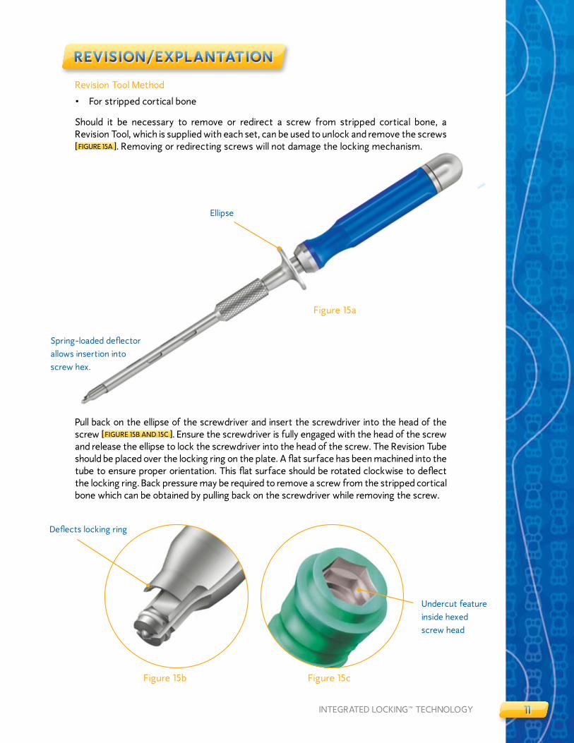
Should it be necessary to remove or redirect a screw from stripped cortical bone, a Revision Tool, which is supplied with each set, can be used to unlock and remove the screws [ FIGURE �5A ]. Removing or redirecting screws will not damage the locking mechanism.
Pull back on the ellipse of the screwdriver and insert the screwdriver into the head of the screw [ FIGURE �5B AND �5C ]. Ensure the screwdriver is fully engaged with the head of the screw and release the ellipse to lock the screwdriver into the head of the screw. The Revision Tube should be placed over the locking ring on the plate. A flat surface has been machined into the tube to ensure proper orientation. This flat surface should be rotated clockwise to deflect the locking ring. Back pressure may be required to remove a screw from the stripped cortical bone which can be obtained by pulling back on the screwdriver while removing the screw.
Deflects locking ring
Undercut feature inside hexed screw head
Figure �5b Figure �5c
Figure �5a
Ellipse
Spring-loaded deflector allows insertion into screw hex.

���� VENTURE™ ANTERIOR CERVICAL PLATE SYSTEM
Place the screwdriver through the Revision Tube [ FIGURE �6A ]. Place the screwdriver in the screw head. The cutout at the working end of the Revision Tube should be placed over the locking ring on the plate [ FIGURE �6B ]. A flat surface has been machined into the tube to insure proper orientation. This flat surface should be rotated clockwise to deflect the locking ring [ FIGURE �6C ]. Turn the screwdriver counterclockwise until the screw head passes the locking ring [ FIGURE �6D ].
ReVISIon/eXPlanTaT Ion
Figure �6b
Figure �6c Figure �6d
Figure �6a
ReVISIon/eXPlanTaT Ion

�3�3INTEGRATED LOCKING™ TECHNOLOGY
PRoDucT oRDeRInG InFoRMaT Ion
IMPLANTS AND INSTRUMENTS
IMPLANTS INSTRUMENTS
ITEM # DESCRIPTION ITEM # DESCRIPTION
97900�9 �9MM PLATE 979090� PLATE BENDER
97900�� ��MM PLATE 9790903 PIN DRIVER
97900�3 �3MM PLATE 9790904 PREFIxATION PINS
97900�5 �5MM PLATE 9790905 FIxED ANGLE DRILL GUIDE
97900�7 �7.5MM PLATE 9790906 VARIABLE ANGLE DRILL GUIDE
9790030 30MM PLATE 9790907 UNIVERSAL HANDLE
979�030 30MM �-LEVEL PLATE 97909�0 FIxED ANGLE AWL
979003� 3�.5MM PLATE 97909�� DRILL/TAP/SCREW (DTS) GUIDE
9790035 35MM PLATE 97909�3 SCREWDRIVER
9790037 37.5MM PLATE 97909�4 REVISION INSTRUMENT
9790040 40MM PLATE 97909�5 ��MM DRILL BIT
979004� 4�.5MM PLATE 97909�6 CASE LID
9790045 45MM PLATE 97909�7 OUTER CASE
9790047 47.5MM PLATE 97909�8 SELF-TAPPING SCREW BLOCK
9790050 50MM PLATE 97909�9 SELF-TAPPING 4.0 SCREW BLOCK LID
979��50 50MM 3-LEVEL PLATE 97909�0 SELF-TAPPING 4.5 SCREW BLOCK LID
979005� 5�.5MM PLATE 97909�� TAP
9790055 55MM PLATE 9790930 LARGE PLATE CADDY
9790057 57.5MM PLATE 979093� LARGE PLATE CADDY LID
9790060 60MM PLATE 9790950 INSTRUMENT TRAY
979006� 6�.5MM PLATE 9790970 UNIVERSAL AWL
9790065 65MM PLATE 9790980 SMALL PLATE CADDY
9790067 67.5MM PLATE 9790985 SMALL PLATE CADDY LID
9790070 70MM PLATE 9790990 SELF-DRILLING SCREW BLOCK
979007� 7�.5MM PLATE 9790995 4.0 SELF-DRILLING SCREW BLOCK LID
9790075 75MM PLATE 9790999 4.5 SELF-DRILLING SCREW BLOCK LID
9790077 77.5MM PLATE 979�000 REVISION TUBE
9790080 80MM PLATE
979008� 8�.5MM PLATE
9790085 85MM PLATE
9790087 87.5MM PLATE
9790090 90MM PLATE
9790095 95MM PLATE
9790�00 �00MM PLATE
9790�05 �05MM PLATE
9790��0 ��0MM PLATE
PRoDucT oRDeRInG InFoRMaT Ion

�4�4 VENTURE™ ANTERIOR CERVICAL PLATE SYSTEM
SCREW OPTIONS
FIxED ANGLE SCREWS VARIABLE ANGLE SCREWS
SELF-TAPPING
ITEM # DESCRIPTION ITEM # DESCRIPTION
9790���* 4.0MM x ��MM SELF-TAPPING 97903��* 4.0MM x ��MM SELF-TAPPING
9790��3 4.0MM x �3MM SELF-TAPPING 97903�3 4.0MM x �3MM SELF-TAPPING
9790��5 4.0MM x �5MM SELF-TAPPING 97903�5 4.0MM x �5MM SELF-TAPPING
9790��7 4.0MM x �7MM SELF-TAPPING 97903�7 4.0MM x �7MM SELF-TAPPING
9790��9* 4.0MM x �9MM SELF-TAPPING 97903�9* 4.0MM x �9MM SELF-TAPPING
9795��3 4.5MM x �3MM SELF-TAPPING 97953�3 4.5MM x �3MM SELF-TAPPING
9795���* 4.5MM x ��MM SELF-TAPPING 97953��* 4.5MM x ��MM SELF-TAPPING
9795��5 4.5MM x �5MM SELF-TAPPING 97953�5 4.5MM x �5MM SELF-TAPPING
9795��7 4.5MM x �7MM SELF-TAPPING 97953�7 4.5MM x �7MM SELF-TAPPING
9795��9* 4.5MM x �9MM SELF-TAPPING 97953�9* 4.0MM x �9MM SELF-TAPPING
SELF-DRILLING
9790���* 4.0MM x ��MM SELF-DRILLING 97903��* 4.0MM x ��MM SELF-DRILLING
9790��3 4.0MM x �3MM SELF-DRILLING 97903�3 4.0MM x �3MM SELF-DRILLING
9790��5 4.0MM x �5MM SELF-DRILLING 97903�5 4.0MM x �5MM SELF-DRILLING
9795���* 4.5MM x ��MM SELF-DRILLING 97953��* 4.5MM x ��MM SELF-DRILLING
9795��3 4.5MM x �3MM SELF-DRILLING 97953�3 4.5MM x �3MM SELF-DRILLING
9795��5 4.5MM x �5MM SELF-DRILLING 97953�5 4.5MM x �5MM SELF-DRILLING
* AVAILABLE UPON REqUEST.
PRoDucT oRDeRInG InFoRMaT Ion Cont inuedPRoDucT oRDeRInG InFoRMaT Ion

Important Information on the VENTURE™ Anterior Cervical Plate SystemPurPose: The VeNTure™ Anterior Cervical Plate system components are temporary implants that are intended for anterior interbody screw fixation of the cervical spine during the development of a cervical spinal fusion. The implantation of the VeNTure™ Anterior Cervical Plate system is via an anterior surgical approach.
DesCriPTioN: The VeNTure™ Anterior Cervical Plate system consists of a variety of bone plates and screws. Fixation is provided by the insertion of bone screws through the openings at each end of the plate into the vertebral bodies of the cervical spine. Associated instruments are also available to facilitate the implantation of the device.
The VeNTure™ Anterior Cervical Plate system implant components are made from titanium alloy, with certain subcomponents manufactured from shape memory alloys (Nitinol – NiTi). These materials are not compatible with other metal alloys. Do not use any of the VeNTure™ Anterior Cervical Plate system components with the components from any other system or manufacturer. No warranties, express or implied, are made. implied warranties of merchantability and fitness for a particular purpose or use are specifically excluded. see the MsD Catalog or price list for further information about warranties and limitations of liability.
iNDiCATioNs: Properly used, this system is intended for anterior interbody screw fixation of the cervical spine. The indications and contraindications of spinal instrumentation systems should be well understood by the surgeon. The system is indicated for use in the temporary stabilization of the anterior spine during the development of cervical spinal fusions in patients with: 1) degenerative disc disease (as defined by neck pain of discogenic origin with degeneration of the disc confirmed by patient history and radiographic studies), 2) trauma (including fractures), 3) tumors, 4) deformity (defined as kyphosis, lordosis, or scoliosis), 5) pseudarthrosis, and/or 6) failed previous fusions.
Nota Bene: This device system is intended for anterior cervical intervertebral body fusions only.
WArNiNG: This device is not approved for screw attachment to the posterior elements (pedicles) of the cervical, thoracic, or lumbar spine.
CoNTrAiNDiCATioNs: Contraindications include, but are not limited to:
1. infection, local to the operative site.
2. signs of local inflammation.
3. Fever or leukocytosis.
4. Morbid obesity.
5. Pregnancy.
6. Mental illness.
7. Any medical or surgical condition, which would preclude the potential benefit of spinal implant surgery, such as the elevation of sedimentation rate unexplained by other diseases, elevation of white blood count (WBC), or a marked left shift in the WBC differential count.
8. rapid joint disease, bone absorption, osteopenia, and/or osteoporosis. osteoporosis is a relative contraindication since this condition may limit the degree of obtainable correction, the amount of mechanical fixation, and/or the quality of the bone graft.
9. suspected or documented metal allergy or intolerance.
10. Any case not needing a bone graft and fusion or where fracture healing is not required.
11. Any case requiring the mixing of metals from different components.
12. Any patient having inadequate tissue coverage over the operative site or where there is inadequate bone stock, bone quality, or anatomical definition.
13. Any case not described in the indications.
14. Any patient unwilling to cooperate with the post-operative instructions.
15. Any time implant utilization would interfere with anatomical structures or expected physiological performance.
PoTeNTiAl ADVerse eVeNTs:
All of the possible adverse events associated with spinal fusion surgery without instrumentation are possible. With instrumentation, a listing of possible adverse events includes, but is not limited to:
1. early or late loosening of any or all of the components.
2. Disassembly, bending, and/or breakage of any or all of the components.
3. Foreign body (allergic) reaction to implants, debris, corrosion products, graft material, including metallosis, staining, tumor formation, and/or auto-immune disease.
4. Pressure on the skin from component parts in patients with inadequate tissue coverage over the implant possibly causing skin penetration, irritation, and/or pain. Bursitis. Tissue damage caused by improper positioning and placement of implants or instruments.
5. Post-operative change in spinal curvature, loss of correction, height, and/or reduction.
6. infection.
7. Dural tears.
8. loss of neurological function, including paralysis (complete or incomplete), dysesthesias, hyperesthesia, anesthesia, paraesthesia, appearance of radiculopathy, and/or the development or continuation of pain, numbness, neuroma, or tingling sensation.
9. Neuropathy, neurological deficits (transient or permanent), bilateral paraplegia, reflex deficits, and/or arachnoiditis.
10. loss of bowel and/or bladder control or other types of urological system compromise.
11. scar formation possibly causing neurological compromise around nerves and/or pain.
12. Fracture, microfracture, resorption, damage, or penetration of any spinal bone and/or bone graft or bone graft harvest site at, above, and/or below the level of surgery.
13. interference with roentgenographic, CT, and/or Mr imaging because of the presence of the implants.
14. Non-union (or pseudarthrosis). Delayed union. Mal-union.
15. Cessation of any potential growth of the operated portion of the spine. loss of spinal mobility or function. inability to perform the activities of daily living.
16. Bone loss or decrease in bone density, possibly caused by stress shielding.
17. Graft donor site complications including pain, fracture, or wound healing problems.
18. Atelectasis, ileus, gastritis, herniated nucleus pulposus, retropulsed graft.
19. Hemorrhage, hematoma, seroma, embolism, edema, stroke, excessive bleeding, phlebitis, wound necrosis, wound dehiscence, or damage to blood vessels.
20. Gastrointestinal and/or reproductive system compromise, including sterility and loss of con-sortium.
21. Development of respiratory problems, e.g. pulmonary embolism, bronchitis, pneumonia, etc.
22. Change in mental status.
23. Death.
Note: Additional surgery may be necessary to correct some of these anticipated adverse events.
WArNiNGs AND PreCAuTioNs: A successful result is not always achieved in every surgical case. This fact is especially true in spinal surgery where many extenuating circumstances may compromise the results. The VeNTure™ Anterior Cervical Plate system is only a temporary implant used for the correction and stabilization of the spine. This system is also intended to be used to augment the development of a spinal fusion by providing temporary stabilization. This device system is not intended to be the sole means of spinal support. Bone grafting must be part of the spinal fusion procedure in which the VeNTure™ Anterior Cervical Plate system is utilized. use of this product without a bone graft or in cases that develop into a non-union will not be successful. This spinal implant cannot withstand body loads without the support of bone. in this event, bending, loosening, disassembly and/or breakage of the device(s) will eventually occur. Preoperative planning and operating procedures, includ-ing knowledge of surgical techniques, proper reduction, and proper selection and placement of the implant are important considerations in the successful utilization of the VeNTure™ Anterior Cervical Plate by the surgeon. Further, the proper selection and compliance of the patient will greatly affect the results. Patients who smoke have been shown to have an increased incidence of non-unions. These patients should be advised of this fact and warned of this consequence. obese, malnourished, and/or alcohol and/or other drug abuse patients are also not good candidates for spine fusion. Patients with poor muscle and bone quality and/or nerve paralysis are also not good candidates for spine fusion. The implants are not prostheses.
PHYsiCiAN NoTe: Although the physician is the learned intermediary between the company and the patient, the important medical information given in this document should be conveyed to the patient.
CAuTioN: FeDerAl lAW (usA) resTriCTs THese DeViCes To sAle BY or oN THe orDer oF A PHYsiCiAN.
other preoperative, intraoperative, and postoperative warnings are as follows:
iMPlANT seleCTioN: The selection of the proper size, shape and design of the implant for each patient is crucial to the success of the procedure. Metallic surgical implants are subject to repeated stresses in use, and their strength is limited by the need to adapt the design to the size and shape of human bones. unless great care is taken in patient selection, proper placement of the implant, and postoperative management to minimize stresses on the implant, such stresses may cause metal fatigue and consequent breakage, bending or loosening of the device before the healing process is complete, which may result in further injury or the need to remove the device prematurely.
PreoPerATiVe:
1. only patients that meet the criteria described in the indications should be selected.
2. Patient conditions and/or predispositions such as those addressed in the aforementioned contraindications should be avoided.
3. Care should be used in the handling and storage of the implant components. The implants should not be scratched or otherwise damaged. implants and instruments should be protected during storage especially from corrosive environments.
4. The type of construct to be assembled for the case should be determined prior to beginning the surgery. An adequate inventory of implant sizes should be available at the time of surgery, including sizes larger and smaller than those expected to be used.
5. since mechanical parts are involved, the surgeon should be familiar with the various components before using the equipment and should personally assemble the devices to verify that all parts and necessary instruments are present before the surgery begins. The VeNTure™ Anterior Cervical Plate system components are not to be combined with the components from another manufacturer. Different metal types should not be used together.
6. All components and instruments should be cleaned and sterilized before use. Additional sterile components should be available in case of an unexpected need.
iNTrAoPerATiVe:
1. Any instruction manuals should be carefully followed.
2. At all times, extreme caution should be used around the spinal cord and nerve roots. Damage to nerves will cause loss of neurological functions.
3. When the configuration of the bone cannot be fitted with an available temporary internal fixa-tion device, and contouring is absolutely necessary, it is recommended that such contouring be gradual and great care be used to avoid notching or scratching the surface of the device(s). The components should not be repeatedly or excessively bent any more than absolutely necessary. The components should not be reverse bent at the same location.
4. The implant surfaces should not be scratched or notched, since such actions may reduce the functional strength of the construct.
5. Bone grafts must be placed in the area to be fused and the graft must be extended from the upper to the lower vertebrae to be fused.
6. Bone cement should not be used since this material will make removal of the components difficult or impossible. The heat generated from the curing process may also cause neurologic damage and bone necrosis.
7. Before closing the soft tissues, all of the screws should be seated onto the plate. recheck the tightness of all screws after finishing to make sure that none has loosened during the tightening of the other screws.
PosToPerATiVe:
The physician’s postoperative directions and warnings to the patient, and the corresponding patient compliance, are extremely important.
1. Detailed instructions on the use and limitations of the device should be given to the patient. if partial weight-bearing is recommended or required prior to firm bony union, the patient must be warned that bending, loosening or breakage of the components are complications which can occur as a result of excessive or early weight-bearing or excessive muscular activity. The risk of bending, loosening, or breakage of a temporary internal fixation device during postoperative rehabilitation may be increased if the patient is active, or if the patient is debilitated, demented or otherwise unable to use crutches or other such weight supporting devices. The patient should be warned to avoid falls or sudden jolts in spinal position.
2. To allow the maximum chances for a successful surgical result: the patient or device should not be exposed to mechanical vibrations that may loosen the device construct. The patient should be warned of this possibility and instructed to limit and restrict physical activities, especially lifting and twisting motions and any type of sport participation. The patient should be advised not to smoke or consume alcohol during the bone graft healing process.
3. The patient should be advised of their inability to bend at the point of spinal fusion and taught to compensate for this permanent physical restriction in body motion.
4. if a non-union develops or if the components loosen, bend, and/or break, the device(s) should be revised and/or removed immediately before serious injury occurs. Failure to immobilize a delayed or non-union of bone will result in excessive and repeated stresses on the implant. By the mechanism of fatigue these stresses can cause eventual bending, loosening, or breakage of the device(s). it is important that immobilization of the spinal surgical site be maintained until firm bony union is established and confirmed by roentgenographic examination. The patient must be adequately warned of these hazards and closely supervised to insure cooperation until bony union is confirmed.
5. The VeNTure™ Anterior Cervical Plate system implants are temporary internal fixation devices. internal fixation devices are designed to stabilize the operative site during the normal healing process. After the spine is fused, these devices serve no functional purpose and should be re-moved. in most patients removal is indicated because the implants are not intended to transfer
support forces developed during normal activities. if the device is not removed following completion of its intended use, one or more of the following complications may occur: (1) Corrosion, with lo-calized tissue reaction or pain, (2) Migration of implant position possibly resulting in injury, (3) risk of additional injury from post-operative trauma, (4) Bending, loosening and/or breakage, which could make removal impractical or difficult, (5) Pain, discomfort, or abnormal sensations due to the presence of the device, (6) Possible increased risk of infection, and (7) Bone loss due to stress shielding.
While the surgeon must make the final decision on implant removal, it is the position of the orthope-dic surgical Manufacturers Association that whenever possible and practical for the individual patient, bone fixation devices should be removed once their service as an aid to healing is accom-plished, particularly in younger and more active patients. Any decision to remove the device should take into consideration the potential risk to the patient of a second surgical procedure and the difficulty of removal. implant removal, should be followed by adequate postoperative management to avoid fracture.
6. Any retrieved devices should be treated in such a manner that reuse in another surgical procedure is not possible. As with all orthopaedic implants, none of the VeNTure™ Anterior Cervical Plate system components should ever be reused under any circumstances.
PACKAGiNG: Packages for each of the components should be intact upon receipt. if a loaner or consignment system is used, all sets should be carefully checked for completeness and all components including instruments should be carefully checked to ensure that there is no damage prior to use. Damaged packages or products should not be used, and should be returned to Medtronic sofamor Danek.
CleANiNG AND DeCoNTAMiNATioN: unless just removed from an unopened Medtronic sofamor Danek package, all instruments and implants must be disassembled (if applicable) and cleaned using neutral cleaners before sterilization and introduction into a sterile surgical field or (if applicable) return of the product to Medtronic sofamor Danek. Cleaning and disinfecting of instruments can be performed with aldehyde-free solvents at higher temperatures. Cleaning and decontamination must include the use of neutral cleaners followed by a deionized water rinse.
NoTe: certain cleaning solutions such as those containing formalin, glutaraldehyde, bleach and/or other alkaline cleaners may damage some devices, particularly instruments; these solutions should not be used. Also, many instruments require disassembly before cleaning.
All products should be treated with care. improper use or handling may lead to damage and/or possible improper functioning of the device.
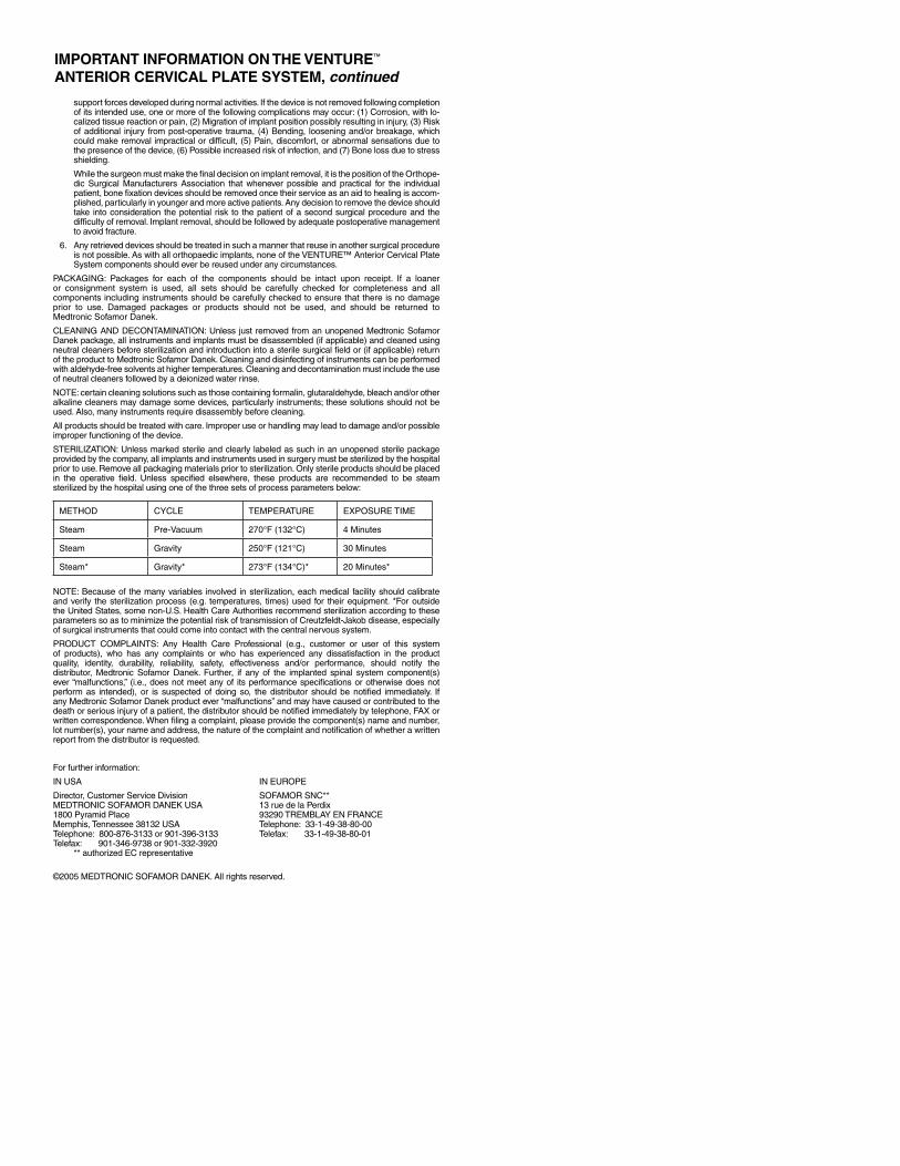
sTeriliZATioN: unless marked sterile and clearly labeled as such in an unopened sterile package provided by the company, all implants and instruments used in surgery must be sterilized by the hospital prior to use. remove all packaging materials prior to sterilization. only sterile products should be placed in the operative field. unless specified elsewhere, these products are recommended to be steam sterilized by the hospital using one of the three sets of process parameters below:
MeTHoD CYCle TeMPerATure eXPosure TiMe
steam Pre-Vacuum 270°F (132°C) 4 Minutes
steam Gravity 250°F (121°C) 30 Minutes
steam* Gravity* 273°F (134°C)* 20 Minutes*
NoTe: Because of the many variables involved in sterilization, each medical facility should calibrate and verify the sterilization process (e.g. temperatures, times) used for their equipment. *For outside the united states, some non-u.s. Health Care Authorities recommend sterilization according to these parameters so as to minimize the potential risk of transmission of Creutzfeldt-Jakob disease, especially of surgical instruments that could come into contact with the central nervous system.
ProDuCT CoMPlAiNTs: Any Health Care Professional (e.g., customer or user of this system of products), who has any complaints or who has experienced any dissatisfaction in the product quality, identity, durability, reliability, safety, effectiveness and/or performance, should notify the distributor, Medtronic sofamor Danek. Further, if any of the implanted spinal system component(s) ever “malfunctions,” (i.e., does not meet any of its performance specifications or otherwise does not perform as intended), or is suspected of doing so, the distributor should be notified immediately. if any Medtronic sofamor Danek product ever “malfunctions” and may have caused or contributed to the death or serious injury of a patient, the distributor should be notified immediately by telephone, FAX or written correspondence. When filing a complaint, please provide the component(s) name and number, lot number(s), your name and address, the nature of the complaint and notification of whether a written report from the distributor is requested.
For further information:
iN usA iN euroPe
Director, Customer service Division soFAMor sNC**MeDTroNiC soFAMor DANeK usA 13 rue de la Perdix1800 Pyramid Place 93290 TreMBlAY eN FrANCeMemphis, Tennessee 38132 usA Telephone: 33-1-49-38-80-00Telephone: 800-876-3133 or 901-396-3133 Telefax: 33-1-49-38-80-01Telefax: 901-346-9738 or 901-332-3920 ** authorized eC representative
©2005 MeDTroNiC soFAMor DANeK. All rights reserved.
ImPoRTANT INfoRmATIoN oN ThE VENTURE™ ANTERIoR CERVICAl PlATE SySTEm, continued


MLITVENACPST5IRN�5��/��5©�005 Medtronic Sofamor Danek USA, Inc. All Rights Reserved.
MEDTRONIC SOFAMOR DANEK USA, INC.Spinal Division Worldwide Headquarters�800 Pyramid PlaceMemphis, TN 38�3�(90�) 396-3�33(800) 876-3�33Customer Service: (800) 933-�635
www.sofamordanek.comFor more information go to www.myspinetools.com
The surgical technique shown is for illustrative purposes only. The technique(s) actually employed in each case will always depend upon the medical judgement of the surgeon exercised before and during surgery as to the best mode of treatment for each patient.