venting & combustion air - aercoaerco.com/sites/default/files/document/document/tag...innovation...
TRANSCRIPT
Innovation Series & ReCon Water Heater GF-5050 Venting and Combustion Air Guide TAG-0043_0Q
12/01/2016 AERCO International, Inc. • 100 Oritani Dr. • Blauvelt, New York 10913 • Phone: 800-526-0288 Page 1 of 39
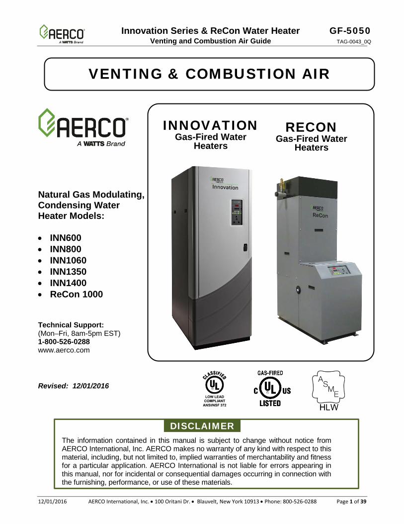
VENTING & COMBUSTION AIR
Natural Gas Modulating, Condensing Water Heater Models: • INN600 • INN800 • INN1060 • INN1350 • INN1400 • ReCon 1000
Technical Support: (Mon–Fri, 8am-5pm EST) 1-800-526-0288 www.aerco.com Revised: 12/01/2016
DISCLAIMER The information contained in this manual is subject to change without notice from AERCO International, Inc. AERCO makes no warranty of any kind with respect to this material, including, but not limited to, implied warranties of merchantability and fitness for a particular application. AERCO International is not liable for errors appearing in this manual, nor for incidental or consequential damages occurring in connection with the furnishing, performance, or use of these materials.
INNOVATION Gas-Fired Water
Heaters
RECON Gas-Fired Water
Heaters
GF-5050 Innovation Series & ReCon Water Heater TAG-0043_0Q Venting and Combustion Air Guide
Page 2 of 39 AERCO International, Inc. • 100 Oritani Dr. • Blauvelt, New York 10913 • Phone: 800-526-0288 12/01/2016
Table of Contents 1. CODES, SAFETY & VENTING SYSTEMS ................................................... 3
1.1. Introduction................................................................................................................... 3 1.2. Applicable Federal Codes ............................................................................................. 3 1.3. Gas Vent Categories .................................................................................................... 4 1.4. Certified Venting Materials for Flue Pipe Systems ........................................................ 5 1.5. Exhaust Vent Connection Components ........................................................................ 7 1.6. PRESSURE RANGE .................................................................................................... 7 1.7. EXHAUST MUFFLER GUIDELINES ............................................................................ 8 1.8. EXHAUST FANS .......................................................................................................... 8 1.9. Elbow Quantity and Separation .................................................................................... 8
2. COMBUSTION AIR SYSTEM ..................................................................... 9
2.1. Combustion Air Requirements ...................................................................................... 9 2.2. Combustion Air from WITHIN the Building .................................................................. 10 2.3. Combustion Air from OUTSIDE the Building ............................................................... 11
2.3.1. Two-Permanent-Openings Method (USA Only) ............................................... 11 2.3.2. One Permanent Opening Method .................................................................... 13
2.4. Combustion Air Pipe Sizing ........................................................................................ 15 2.5. Common Combustion Air Systems ............................................................................. 16
3. VENT SYSTEM ........................................................................................ 19
3.1. Vent Installation .......................................................................................................... 20 3.2. Installation Procedure for Venting System Through a Wall ......................................... 22 3.3. Installation Procedure for Vertical Venting .................................................................. 24 3.4. Vent Pipe Sizing * ....................................................................................................... 25 3.5. Common Vent Pipe Sizing .......................................................................................... 25 3.6. Common Vent CONDENSATE DRAINAGE................................................................ 27 3.7. Combustion Air Duct Pressure Drop Tables ............................................................... 28 3.8. Flue Vent Pressure Drop Tables ................................................................................. 36
Innovation Series & ReCon Water Heater GF-5050 Venting and Combustion Air Guide TAG-0043_0Q
12/01/2016 AERCO International, Inc. • 100 Oritani Dr. • Blauvelt, New York 10913 • Phone: 800-526-0288 Page 3 of 39
1. CODES, SAFETY & VENTING SYSTEMS
1.1. INTRODUCTION The AERCO gas-fired water heater is a high efficiency, forced draft, domestic hot water heating unit with unique venting capabilities. All venting options (which include horizontal and vertical discharges, direct vent, and manifolded vent breeching), typically exceed the capabilities of competing combustion equipment. These and other features enable AERCO water heaters to provide extremely high thermal efficiencies and optimum temperature control under widely varying conditions. It is therefore critical that the flue gas vent and combustion air system be designed to maintain these objectives.
The high efficiency is achieved through air/fuel modulation and the release of heat energy from the moisture condensing in the combustion products. Because condensation can occur in the exhaust vent system, a means must be provided to remove the moisture accumulation. Each model should be fitted with the supplied condensate removal trap.
The design guidelines in this bulletin provide broad latitude while meeting the objectives of safety, longevity and optimum performance.
1.2. APPLICABLE FEDERAL CODES UNITED STATES:
NFPA 54/ANSI Z223.1……….. National Fuel Gas Code NFPA/ANSI 211………………. Chimneys, Fireplaces, Vents and Solid Fuel Burning Appliances
CANADA:
CSA B149.1…………………… Installation Codes for Gas-Burning Equipment CSA B149.2…………………… Installation Codes for Gas-Burning Equipment
The above listed codes contain information for gas vented appliances requiring Category II, III and IV, vent sizing, location, air space clearances to combustibles and safe installation practices. The gas vent installer must be in compliance with the above codes, as well as Local Codes and Regulations.
ALL INSTALLATIONS OF WATER HEATERS AND VENTING SHOULD BE DONE ONLY BY QUALIFIED VENTING SYSTEMS PERSONNEL AND IN ACCORDANCE WITH THE MANUFACTURER’S RECOMMENDATIONS. INSTALLING OR VENTING A HEATER OR ANY OTHER GAS APPLIANCE WITH IMPROPER METHODS OR MATERIALS MAY RESULT IN SERIOUS INJURY OR DEATH DUE TO FIRE OR TO ASPHYXIATION FROM POISONOUS GASES (CARBON MONOXIDE IS ODORLESS AND INVISIBLE).
WARNING
GF-5050 Innovation Series & ReCon Water Heater TAG-0043_0Q Venting and Combustion Air Guide
Page 4 of 39 AERCO International, Inc. • 100 Oritani Dr. • Blauvelt, New York 10913 • Phone: 800-526-0288 12/01/2016
• FOR CORRECT INSTALLATION OF VENT SYSTEM, READ ALL
OF THESE INSTRUCTIONS AND REFER TO THE VENT PIPE MANUFACTURER’S INSTRUCTIONS.
• FAILURE TO USE THE VENTING SYSTEM DESCRIBED IN THIS DOCUMENT WILL VOID THE MANUFACTURER’S WARRANTY AND MAY RESULT IN RAPID DETERIORATION OF THE VENTING SYSTEM, CREATING A POTENTIAL HEALTH HAZARD.
• FAULTY VENT INSTALLATION CAN ALLOW TOXIC FUMES TO BE RELEASED INTO LIVING AREAS. THIS MAY CAUSE SERIOUS BODILY INJURY OR PROPERTY DAMAGE. IMPROPER ASSEMBLY MAY ALSO AFFECT VENT PERFORMANCE.
• INSTALL SEPARATE VENTS FOR FORCED EXHAUST APPLIANCES AND NATURAL DRAFT APPLIANCES. A COMMON VENT BETWEEN NATURAL DRAFT AND FORCED EXHAUST APPLIANCES MAY CAUSE TOXIC GASES TO EXHAUST THROUGH THE NATURAL DRAFT APPLIANCE RATHER THAN TO OUTSIDE AIR. BREATHING EXHAUST GASES WILL CAUSE SERIOUS PERSONAL INJURY OR DEATH.
1.3. GAS VENT CATEGORIES
Innovation and ReCon water heaters are approved for a Category II and Category IV vent configuration as well as for ducted combustion air installations.
Provisions for combustion and ventilation air in accordance with Section 5.3, (Air for Combustion and Ventilation) of the National Fuel Gas Code - ANSI Z223.1, or Sections 7.2, 7.3, or 7.4 of CAN/CSA B149.1, Installation Codes, or applicable provisions of the local building codes.
Federal Codes have categorized gas appliances by the vented flue gas pressure and temperature as follows:
• Category I, being a gas appliance that operates with a non-positive vent (or natural drafted vent) connector with a flue gas pressure and temperature at least 140°F (60°C) above its dew point.
• Category II, being a gas appliance that operates with a non-positive vent (or natural drafted vent) connector with a flue gas pressure and temperature less than 140°F (60°C) above its dew point.
• Category III, being a gas appliance that operates with a positive vent (fan forced vent) connector with a flue gas pressure and temperature at least 140°F (60°C) above its dew point.
WARNINGS
CAUTION
Innovation Series & ReCon Water Heater GF-5050 Venting and Combustion Air Guide TAG-0043_0Q
12/01/2016 AERCO International, Inc. • 100 Oritani Dr. • Blauvelt, New York 10913 • Phone: 800-526-0288 Page 5 of 39
• Category IV, being a gas appliance that operates with a positive vent (fan forced vent) connector with a flue gas pressure and temperature less than 140°F (60°C) above its dew point.
• Direct Vent, a gas appliance is constructed and installed so that all air for combustion is derived directly from the outdoors and all flue gases are discharged to the outdoors.
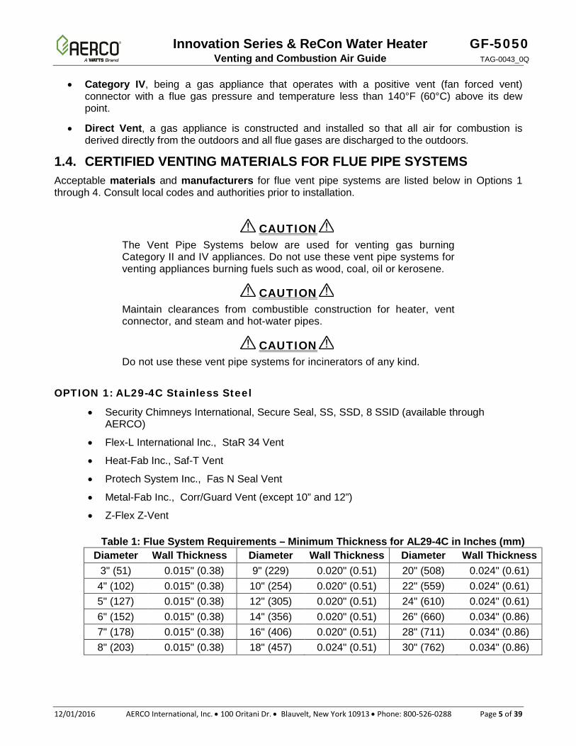
1.4. CERTIFIED VENTING MATERIALS FOR FLUE PIPE SYSTEMS Acceptable materials and manufacturers for flue vent pipe systems are listed below in Options 1 through 4. Consult local codes and authorities prior to installation.
The Vent Pipe Systems below are used for venting gas burning Category II and IV appliances. Do not use these vent pipe systems for venting appliances burning fuels such as wood, coal, oil or kerosene.
Maintain clearances from combustible construction for heater, vent connector, and steam and hot-water pipes.
Do not use these vent pipe systems for incinerators of any kind.
OPTION 1: AL29-4C Stainless Steel
• Security Chimneys International, Secure Seal, SS, SSD, 8 SSID (available through AERCO)
• Flex-L International Inc., StaR 34 Vent
• Heat-Fab Inc., Saf-T Vent
• Protech System Inc., Fas N Seal Vent
• Metal-Fab Inc., Corr/Guard Vent (except 10” and 12”)
• Z-Flex Z-Vent
Table 1: Flue System Requirements – Minimum Thickness for AL29-4C in Inches (mm) Diameter Wall Thickness Diameter Wall Thickness Diameter Wall Thickness
3" (51) 0.015" (0.38) 9" (229) 0.020" (0.51) 20" (508) 0.024" (0.61) 4" (102) 0.015" (0.38) 10" (254) 0.020" (0.51) 22" (559) 0.024" (0.61) 5" (127) 0.015" (0.38) 12" (305) 0.020" (0.51) 24" (610) 0.024" (0.61) 6" (152) 0.015" (0.38) 14" (356) 0.020" (0.51) 26" (660) 0.034" (0.86) 7" (178) 0.015" (0.38) 16" (406) 0.020" (0.51) 28" (711) 0.034" (0.86) 8" (203) 0.015" (0.38) 18" (457) 0.024" (0.51) 30" (762) 0.034" (0.86)
CAUTION
CAUTION
CAUTION
GF-5050 Innovation Series & ReCon Water Heater TAG-0043_0Q Venting and Combustion Air Guide
Page 6 of 39 AERCO International, Inc. • 100 Oritani Dr. • Blauvelt, New York 10913 • Phone: 800-526-0288 12/01/2016
OPTION 2: VP1738A
• Van-Packer Company, Inc., Model CS Special Gas Vent
OPTION 3: Polypropylene
• DuraVent, PolyPro Commercial. NOTE: Centrotherm provides the adapter when ordering through them directly. However, when ordering through DuraVent, the customer must purchase the required adapter separately. Refer to section 1.5 for adapter information
• Centrotherm ECO Systems, InnoFlue Single Walk Commercial
OPTION 4: PVC/cPVC *
If needed, a PVC Vent Adapter is provided in the Spares Kit included with each Innovation water heater.
* NOTE
PVC and cPVC venting are not allowed for ReCon water heaters.
Because Innovation and ReCon water heaters are Category II and IV appliances, they require special attention to exhaust venting and combustion air details. The exhaust vent MUST be UL listed for use with Category II and IV appliances.
Proper clearances to combustibles must be maintained per UL and vent manufacturer requirements. The UL, National Fuel Gas Code (ANSI Z223.1/ NFPA54)1 and CSA B149.1-10 guidelines are often the basis for state and local codes. AERCO's recommendations follow the guidelines of these agencies, unless more stringent codes govern the installation site. The venting and combustion air systems must meet all applicable code requirements.
All Canada installations must comply with CSA B149.1 installation code.
Innovation Series & ReCon Water Heater GF-5050 Venting and Combustion Air Guide TAG-0043_0Q
12/01/2016 AERCO International, Inc. • 100 Oritani Dr. • Blauvelt, New York 10913 • Phone: 800-526-0288 Page 7 of 39
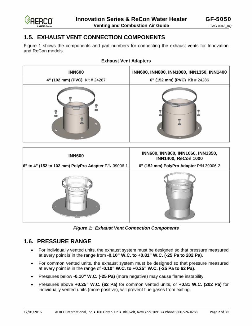
1.5. EXHAUST VENT CONNECTION COMPONENTS Figure 1 shows the components and part numbers for connecting the exhaust vents for Innovation and ReCon models.
Exhaust Vent Adapters
INN600 INN600, INN800, INN1060, INN1350, INN1400 4” (102 mm) (PVC) Kit # 24287 6” (152 mm) (PVC) Kit # 24286
INN600 INN600, INN800, INN1060, INN1350, INN1400, ReCon 1000
6” to 4” (152 to 102 mm) PolyPro Adapter P/N 39006-1 6” (152 mm) PolyPro Adapter P/N 39006-2
Figure 1: Exhaust Vent Connection Components
1.6. PRESSURE RANGE • For individually vented units, the exhaust system must be designed so that pressure measured
at every point is in the range from -0.10” W.C. to +0.81” W.C. (-25 Pa to 202 Pa).
• For common vented units, the exhaust system must be designed so that pressure measured at every point is in the range of -0.10” W.C. to +0.25” W.C. (-25 Pa to 62 Pa).
• Pressures below -0.10” W.C. (-25 Pa) (more negative) may cause flame instability.
• Pressures above +0.25” W.C. (62 Pa) for common vented units, or +0.81 W.C. (202 Pa) for individually vented units (more positive), will prevent flue gases from exiting.
GF-5050 Innovation Series & ReCon Water Heater TAG-0043_0Q Venting and Combustion Air Guide
Page 8 of 39 AERCO International, Inc. • 100 Oritani Dr. • Blauvelt, New York 10913 • Phone: 800-526-0288 12/01/2016
1.7. EXHAUST MUFFLER GUIDELINES Both Innovation and ReCon units require an exhaust muffler when they are installed in a noise-sensitive application and when the exhaust vent ducting is relatively short in length. The following criteria should be used to determine when to include a field-installed muffler in an Innovation and ReCon installations:
• The total linear length from exhaust to termination is less than 25 linear feet (7.5 linear m) in length and the vent terminates in close proximity to residences, offices, hotel/hospital rooms, classrooms etc.
For manifolded exhaust systems, the total vertical section includes only the common vertical; individual unit vertical connectors are not included in the determination.
EXAMPLE: If the installation has a 20 foot (6.1 m) common vertical, and each unit has a 10-foot vertical connector, the total vertical section is only 20 feet (6.1 m). Because this length is less than 25 linear feet (7.5 m), a muffler is required.
If the muffler must be mounted horizontally, add a condensate drain and trap with the drain port oriented downward.
Contact your local AERCO sales representative for more information on the AERCO exhaust muffler.
1.8. EXHAUST FANS If the Innovation or ReCon water heater’s exhaust system incorporates an exhaust fan, the system designer must size the vent pipe diameters, select the fan and determine the location of the fan sensor to maintain a -0.1” to +0.25” W.C. (-25 Pa to 62 Pa) pressure range at the outlet of each boiler. Also, the designer must ensure that the exhaust fan material is acceptable for use with Category IV appliances.
1.9. ELBOW QUANTITY AND SEPARATION The quantity and angle of elbows and the distances between them can influence the system’s exhaust and combustion air pressures, as well as its acoustical behavior. Designers should consider minimizing the quantity of elbows in the design and the use of angles less than 90°, whenever possible. Five or fewer elbows are recommended for individual venting/connections; five or fewer are recommended for common sections. The minimum distance required between two elbows is 5 feet (1.52 m).
Innovation Series & ReCon Water Heater GF-5050 Venting and Combustion Air Guide TAG-0043_0Q
12/01/2016 AERCO International, Inc. • 100 Oritani Dr. • Blauvelt, New York 10913 • Phone: 800-526-0288 Page 9 of 39
2. COMBUSTION AIR SYSTEM
AIR OPENINGS TO COMBUSTION AREA MUST NOT BE OBSTRUCTED. USE THE INFORMATION BELOW TO ENSURE THAT ADEQUATE COMBUSTION AIR IS MAINTAINED.
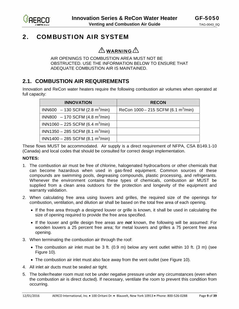
2.1. COMBUSTION AIR REQUIREMENTS Innovation and ReCon water heaters require the following combustion air volumes when operated at full capacity:
INNOVATION RECON INN600 – 130 SCFM (2.8 m3/min) ReCon 1000 – 215 SCFM (6.1 m3/min)
INN800 – 170 SCFM (4.8 m3/min)
INN1060 – 225 SCFM (6.4 m3/min)
INN1350 – 285 SCFM (8.1 m3/min)
INN1400 – 285 SCFM (8.1 m3/min)
These flows MUST be accommodated. Air supply is a direct requirement of NFPA, CSA B149.1-10 (Canada) and local codes that should be consulted for correct design implementation.
NOTES: 1. The combustion air must be free of chlorine, halogenated hydrocarbons or other chemicals that
can become hazardous when used in gas-fired equipment. Common sources of these compounds are swimming pools, degreasing compounds, plastic processing, and refrigerants. Whenever the environment contains these types of chemicals, combustion air MUST be supplied from a clean area outdoors for the protection and longevity of the equipment and warranty validation.
2. When calculating free area using louvers and grilles, the required size of the openings for combustion, ventilation, and dilution air shall be based on the total free area of each opening.
• If the free area through a designed louver or grille is known, it shall be used in calculating the size of opening required to provide the free area specified.
• If the louver and grille design free areas are not known, the following will be assumed: For wooden louvers a 25 percent free area; for metal louvers and grilles a 75 percent free area opening.
3. When terminating the combustion air through the roof:
• The combustion air inlet must be 3 ft. (0.9 m) below any vent outlet within 10 ft. (3 m) (see Figure 10).
• The combustion air inlet must also face away from the vent outlet (see Figure 10).
4. All inlet air ducts must be sealed air tight.
5. The boiler/heater room must not be under negative pressure under any circumstances (even when the combustion air is direct ducted). If necessary, ventilate the room to prevent this condition from occurring.
WARNING
GF-5050 Innovation Series & ReCon Water Heater TAG-0043_0Q Venting and Combustion Air Guide
Page 10 of 39 AERCO International, Inc. • 100 Oritani Dr. • Blauvelt, New York 10913 • Phone: 800-526-0288 12/01/2016
• Non-motorized louvers and grilles must be fixed in an open
position. • Minimum screens mesh size shall not be smaller than ¼
inch (6.4 mm) mesh.
6. Air intakes must not be located in the proximity of garages, industrial and medical hood venting, loading docks or refrigerant vent lines. Boilers must not be installed in the proximity of activities that generate dust if that dust can enter the boiler intake. Boilers must be located to prevent moisture and precipitation from entering combustion air inlets.
7. If a water heater is used, temporarily, to provide heat during ongoing building construction or renovation, accumulated drywall dust, sawdust and similar particles can:
• Accumulate in the unit’s combustion air intake and block combustion air flow • Accumulate over the burner surface and restrict flow of air/fuel mixture
In these situations, AERCO requires that a disposable air intake filter be installed, temporarily, above the combustion air inlet. Air filters may be required year-round in instances in which dust or debris can enter the combustion air tube. Consult the Operations and Maintenance Manual for details.
8. Combustion air temperatures as low as -30°F (-34°C ) can be used without affecting the integrity of the equipment; however, the combustion settings may require adjustment to compensate for site conditions.
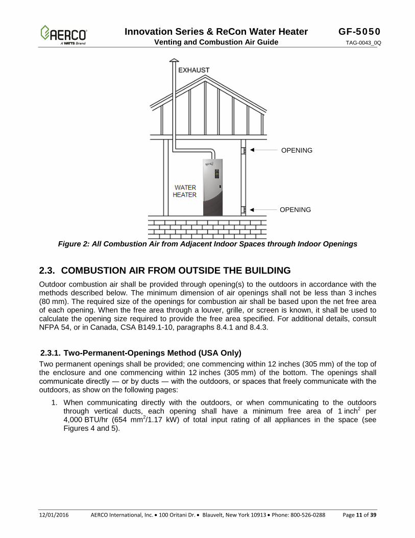
2.2. COMBUSTION AIR FROM WITHIN THE BUILDING Wherever combustion air originates from in the building, it must be provided to the equipment room from two permanent openings to an interior room (or rooms). Openings connecting indoor spaces shall be sized and located in accordance with the following:
• Each opening shall have a minimum free area of 1 inch2 per 1,000 BTU/hr (654 mm2/0.29 kW) of total input rating of all appliances in the space, but not less than 100 inch2 (0.06 m2).
• One opening shall commence within 12 inches (305 mm) of the top of the enclosure, and one opening shall commence within 12 inches (305 mm) of the bottom. (See Figure 2).
WARNING
Innovation Series & ReCon Water Heater GF-5050 Venting and Combustion Air Guide TAG-0043_0Q
12/01/2016 AERCO International, Inc. • 100 Oritani Dr. • Blauvelt, New York 10913 • Phone: 800-526-0288 Page 11 of 39
Figure 2: All Combustion Air from Adjacent Indoor Spaces through Indoor Openings
2.3. COMBUSTION AIR FROM OUTSIDE THE BUILDING Outdoor combustion air shall be provided through opening(s) to the outdoors in accordance with the methods described below. The minimum dimension of air openings shall not be less than 3 inches (80 mm). The required size of the openings for combustion air shall be based upon the net free area of each opening. When the free area through a louver, grille, or screen is known, it shall be used to calculate the opening size required to provide the free area specified. For additional details, consult NFPA 54, or in Canada, CSA B149.1-10, paragraphs 8.4.1 and 8.4.3.
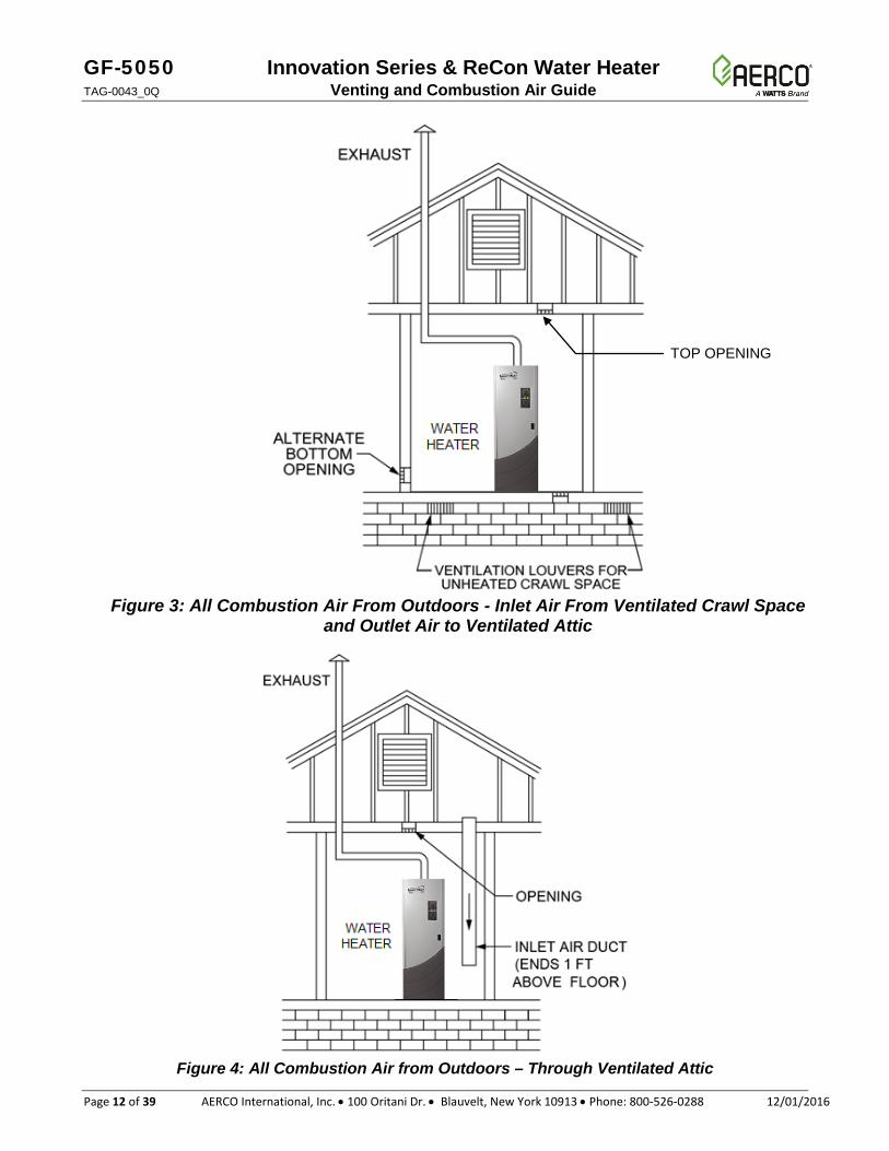
2.3.1. Two-Permanent-Openings Method (USA Only) Two permanent openings shall be provided; one commencing within 12 inches (305 mm) of the top of the enclosure and one commencing within 12 inches (305 mm) of the bottom. The openings shall communicate directly ― or by ducts ― with the outdoors, or spaces that freely communicate with the outdoors, as show on the following pages:
1. When communicating directly with the outdoors, or when communicating to the outdoors through vertical ducts, each opening shall have a minimum free area of 1 inch2 per 4,000 BTU/hr (654 mm2/1.17 kW) of total input rating of all appliances in the space (see Figures 4 and 5).
OPENING
OPENING
GF-5050 Innovation Series & ReCon Water Heater TAG-0043_0Q Venting and Combustion Air Guide
Page 12 of 39 AERCO International, Inc. • 100 Oritani Dr. • Blauvelt, New York 10913 • Phone: 800-526-0288 12/01/2016
Figure 3: All Combustion Air From Outdoors - Inlet Air From Ventilated Crawl Space
and Outlet Air to Ventilated Attic
Figure 4: All Combustion Air from Outdoors – Through Ventilated Attic
TOP OPENING
Innovation Series & ReCon Water Heater GF-5050 Venting and Combustion Air Guide TAG-0043_0Q
12/01/2016 AERCO International, Inc. • 100 Oritani Dr. • Blauvelt, New York 10913 • Phone: 800-526-0288 Page 13 of 39
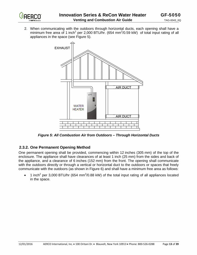
2. When communicating with the outdoors through horizontal ducts, each opening shall have a minimum free area of 1 inch2 per 2,000 BTU/hr. (654 mm2/0.59 kW) of total input rating of all appliances in the space (see Figure 5).
Figure 5: All Combustion Air from Outdoors – Through Horizontal Ducts
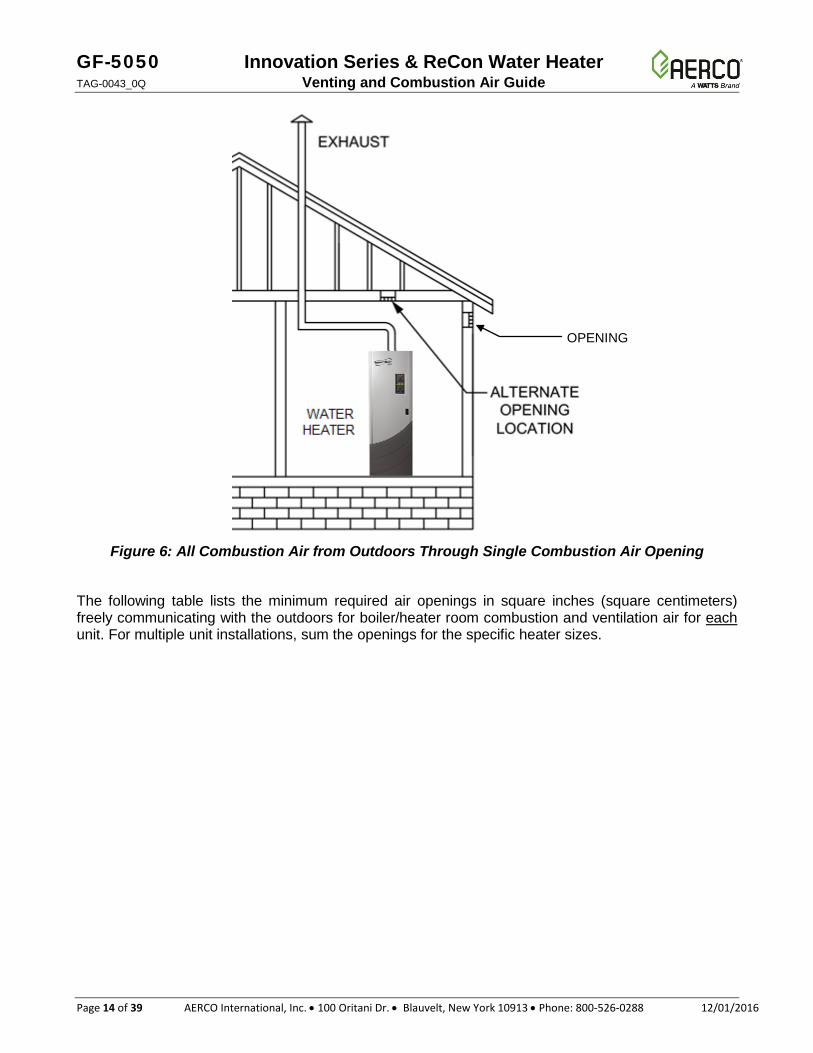
2.3.2. One Permanent Opening Method One permanent opening shall be provided, commencing within 12 inches (305 mm) of the top of the enclosure. The appliance shall have clearances of at least 1 inch (25 mm) from the sides and back of the appliance, and a clearance of 6 inches (152 mm) from the front. The opening shall communicate with the outdoors directly or through a vertical or horizontal duct to the outdoors or spaces that freely communicate with the outdoors (as shown in Figure 6) and shall have a minimum free area as follows:
• 1 inch2 per 3,000 BTU/hr (654 mm2/0.88 kW) of the total input rating of all appliances located in the space.
GF-5050 Innovation Series & ReCon Water Heater TAG-0043_0Q Venting and Combustion Air Guide
Page 14 of 39 AERCO International, Inc. • 100 Oritani Dr. • Blauvelt, New York 10913 • Phone: 800-526-0288 12/01/2016
Figure 6: All Combustion Air from Outdoors Through Single Combustion Air Opening
The following table lists the minimum required air openings in square inches (square centimeters) freely communicating with the outdoors for boiler/heater room combustion and ventilation air for each unit. For multiple unit installations, sum the openings for the specific heater sizes.
OPENING
Innovation Series & ReCon Water Heater GF-5050 Venting and Combustion Air Guide TAG-0043_0Q
12/01/2016 AERCO International, Inc. • 100 Oritani Dr. • Blauvelt, New York 10913 • Phone: 800-526-0288 Page 15 of 39
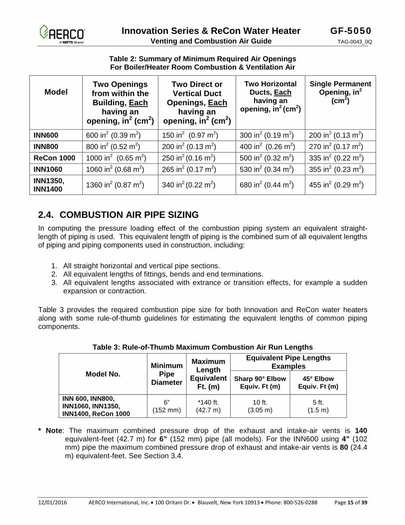
Table 2: Summary of Minimum Required Air Openings For Boiler/Heater Room Combustion & Ventilation Air
Model Two Openings from within the Building, Each
having an opening, in2 (cm2)
Two Direct or Vertical Duct
Openings, Each having an
opening, in2 (cm2)
Two Horizontal Ducts, Each having an
opening, in2 (cm2)
Single Permanent Opening, in2
(cm2)
INN600 600 in2 (0.39 m2) 150 in2 (0.97 m2) 300 in2 (0.19 m2) 200 in2 (0.13 m2) INN800 800 in2 (0.52 m2) 200 in2 (0.13 m2) 400 in2 (0.26 m2) 270 in2 (0.17 m2) ReCon 1000 1000 in2 (0.65 m2) 250 in2 (0.16 m2) 500 in2 (0.32 m2) 335 in2 (0.22 m2) INN1060 1060 in2 (0.68 m2) 265 in2 (0.17 m2) 530 in2 (0.34 m2) 355 in2 (0.23 m2) INN1350, INN1400 1360 in2 (0.87 m2) 340 in2 (0.22 m2) 680 in2 (0.44 m2) 455 in2 (0.29 m2)
2.4. COMBUSTION AIR PIPE SIZING In computing the pressure loading effect of the combustion piping system an equivalent straight-length of piping is used. This equivalent length of piping is the combined sum of all equivalent lengths of piping and piping components used in construction, including:
1. All straight horizontal and vertical pipe sections. 2. All equivalent lengths of fittings, bends and end terminations. 3. All equivalent lengths associated with extrance or transition effects, for example a sudden
expansion or contraction. Table 3 provides the required combustion pipe size for both Innovation and ReCon water heaters along with some rule-of-thumb guidelines for estimating the equivalent lengths of common piping components.
Table 3: Rule-of-Thumb Maximum Combustion Air Run Lengths
Model No. Minimum
Pipe Diameter
Maximum Length
Equivalent Ft. (m)
Equivalent Pipe Lengths Examples
Sharp 90° Elbow Equiv. Ft (m)
45° Elbow Equiv. Ft (m)
INN 600, INN800, INN1060, INN1350, INN1400, ReCon 1000
6” (152 mm)
*140 ft. (42.7 m)
10 ft. (3.05 m)
5 ft. (1.5 m)
* Note: The maximum combined pressure drop of the exhaust and intake-air vents is 140
equivalent-feet (42.7 m) for 6” (152 mm) pipe (all models). For the INN600 using 4” (102 mm) pipe the maximum combined pressure drop of exhaust and intake-air vents is 80 (24.4 m) equivalent-feet. See Section 3.4.
GF-5050 Innovation Series & ReCon Water Heater TAG-0043_0Q Venting and Combustion Air Guide
Page 16 of 39 AERCO International, Inc. • 100 Oritani Dr. • Blauvelt, New York 10913 • Phone: 800-526-0288 12/01/2016
Rule-of-Thumb Examples – Standard North American units of measure: 1. A 40 foot length of combustion air pipe and 1 sharp 90° elbow plus two termination 90° elbows
add up to 40 ft. + 10 ft. + (2 x 10 ft.) = 70 equivalent ft.
2. A 30 foot (9.1 m) length of combustion air pipe and 2 sharp 90° elbows plus two termination 90° elbows add up to 30 ft. + (2 x 10 ft.) + (2 x 10 ft.) = 70 equivalent ft. (21.3 m).
Rule-of-Thumb Examples – Metric units of measure: 1. A 12 m length of combustion air pipe and 1 sharp 90° elbow plus two termination 90° elbows
add up to 12 m + 3 m + (2 x 3 m) = 21 equivalent m
2. A 9 m length of combustion air pipe and 2 sharp 90° elbows plus two termination 90° elbows add up to 9 m + (2 x 3 m) + (2 x 3 m) = 21 m
For more detailed analysis see sections 3.6 and 3.7 and Example.
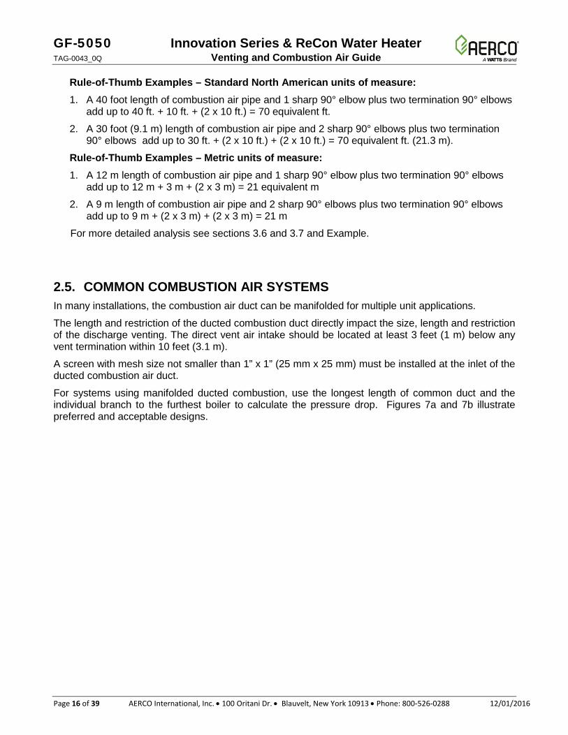
2.5. COMMON COMBUSTION AIR SYSTEMS In many installations, the combustion air duct can be manifolded for multiple unit applications.
The length and restriction of the ducted combustion duct directly impact the size, length and restriction of the discharge venting. The direct vent air intake should be located at least 3 feet (1 m) below any vent termination within 10 feet (3.1 m).
A screen with mesh size not smaller than 1” x 1” (25 mm x 25 mm) must be installed at the inlet of the ducted combustion air duct.
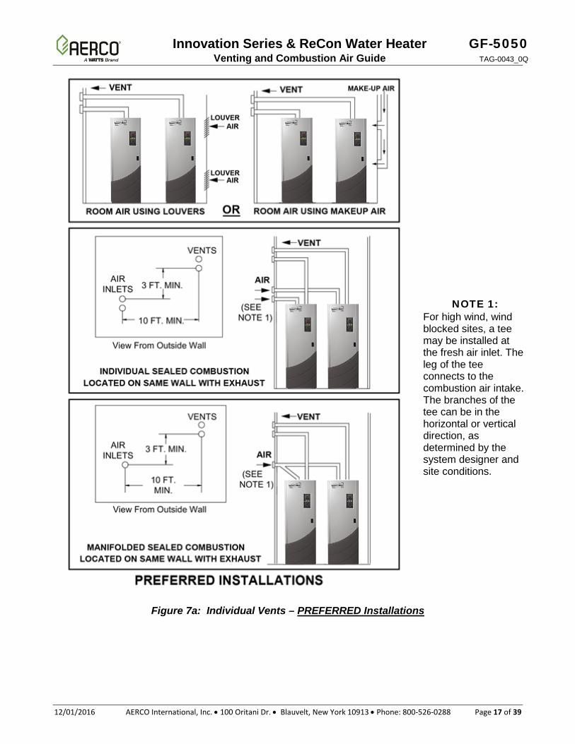
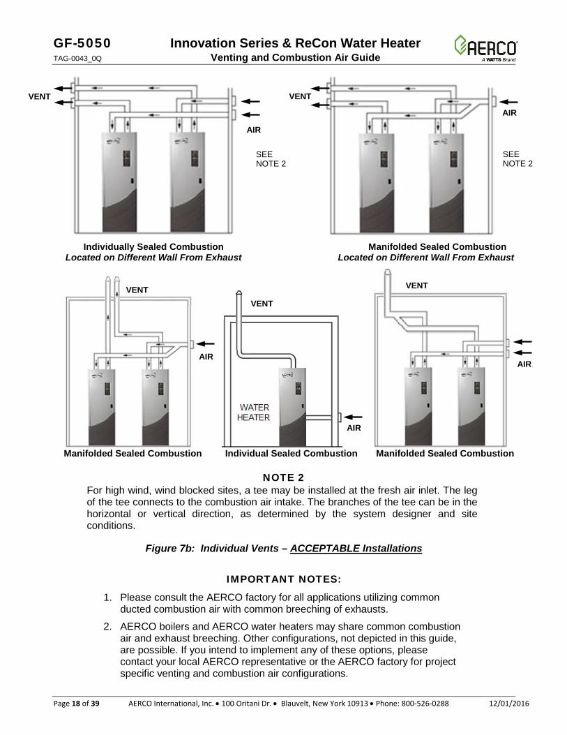
For systems using manifolded ducted combustion, use the longest length of common duct and the individual branch to the furthest boiler to calculate the pressure drop. Figures 7a and 7b illustrate preferred and acceptable designs.
Innovation Series & ReCon Water Heater GF-5050 Venting and Combustion Air Guide TAG-0043_0Q
12/01/2016 AERCO International, Inc. • 100 Oritani Dr. • Blauvelt, New York 10913 • Phone: 800-526-0288 Page 17 of 39
Figure 7a: Individual Vents – PREFERRED Installations
NOTE 1: For high wind, wind blocked sites, a tee may be installed at the fresh air inlet. The leg of the tee connects to the combustion air intake. The branches of the tee can be in the horizontal or vertical direction, as determined by the system designer and site conditions.
GF-5050 Innovation Series & ReCon Water Heater TAG-0043_0Q Venting and Combustion Air Guide
Page 18 of 39 AERCO International, Inc. • 100 Oritani Dr. • Blauvelt, New York 10913 • Phone: 800-526-0288 12/01/2016
Individually Sealed Combustion Manifolded Sealed Combustion Located on Different Wall From Exhaust Located on Different Wall From Exhaust
Manifolded Sealed Combustion Individual Sealed Combustion Manifolded Sealed Combustion
NOTE 2 For high wind, wind blocked sites, a tee may be installed at the fresh air inlet. The leg of the tee connects to the combustion air intake. The branches of the tee can be in the horizontal or vertical direction, as determined by the system designer and site conditions.
Figure 7b: Individual Vents – ACCEPTABLE Installations
IMPORTANT NOTES:
1. Please consult the AERCO factory for all applications utilizing common ducted combustion air with common breeching of exhausts.
2. AERCO boilers and AERCO water heaters may share common combustion air and exhaust breeching. Other configurations, not depicted in this guide, are possible. If you intend to implement any of these options, please contact your local AERCO representative or the AERCO factory for project specific venting and combustion air configurations.
VENT VENT
AIR
AIR
SEE NOTE 2
SEE NOTE 2
AIR
AIR
AIR
VENT VENT
VENT
Innovation Series & ReCon Water Heater GF-5050 Venting and Combustion Air Guide TAG-0043_0Q
12/01/2016 AERCO International, Inc. • 100 Oritani Dr. • Blauvelt, New York 10913 • Phone: 800-526-0288 Page 19 of 39
3. VENT SYSTEM The heater vent is fundamental for correct operation. Being a condensing heater, combustion gases are discharged at a very low temperature. It is therefore necessary for the venting system to be perfectly impermeable to combustion products condensate and to be made of corrosion resistant materials. Typical Category IV venting and ducted combustion air illustrations are shown in Figures 3 through 7. The various funnel joints shall be well sealed and/or equipped with suitable gaskets, in order to avoid any condensate drain and/or air intake. Ensure that the heater’s vent section and height conform to national and local regulations (see Section 1.2 APPLICABLE FEDERAL CODES of this guide).
The exhaust vent system must be pitched back toward the water heater unit by a minimum of 1/4 inch per foot (21 mm/m) of duct length to enable condensate to drain back to the unit for disposal. Low spots in the vent must be avoided to prevent the condensate from collecting.
The condensate trap assembly is located directly below the exhaust manifold. Plastic hose should be connected to the trap assembly and run to drain. Care should be taken to avoid hose kinks and to avoid raising the hose above the trap assembly. Condensate should flow freely to drain. The condensate-to-drain run must not be hard-piped so the trap can be removed periodically for maintenance purposes.
If the condensate must be lifted above the trap assembly to a drain, it should be drained into a sump. From there, a pump can lift the condensate away.
Innovation and ReCon units will produce the following maximum condensate quantities in the full condensing mode:
INNOVATION RECON
INN600
4.5 gallons per hour ReCon 1000
8 gallons per hour 0.28 L/min 0.50 L/min
INN800 6 gallons per hour 0.38 L/min
INN1060 8 gallons per hour 0.50 L/min
INN1350 INN1400
11 gallons per hour 0.69 L/min
Condensate drain systems must be sized for full condensing mode.
In multiple water heater applications, it is common to manifold these drains together in a plastic pipe manifold to a floor drain. Condensate manifolds must be large enough to handle the anticipated flow and must be properly secured and protected. Manifolds are generally located behind the units so that short runs of plastic tubing into the manifold can be used for the condensate drain. A base drain must be installed at the bottom of vertical common flue piping.
The pH level of the condensate produced by AERCO water heaters ranges between 3.0 and 3.2. The installation should be designed in accordance with local codes that specify acceptable pH limits. If required, any type of commercially available neutralizer may be used. For water heaters designed for connection to gas vents or chimneys, vent installations shall be in accordance with Part 7, Venting of Equipment, of the National Fuel Gas Code, ANSI Z223.1, or Section 7, Venting Systems and Air Supply for Appliances, of the CAN/CSA B149, Installation Codes, or applicable provisions of the local building codes.
GF-5050 Innovation Series & ReCon Water Heater TAG-0043_0Q Venting and Combustion Air Guide
Page 20 of 39 AERCO International, Inc. • 100 Oritani Dr. • Blauvelt, New York 10913 • Phone: 800-526-0288 12/01/2016
The vent system for Innovation and ReCon heaters must be installed in accordance with AERCO’s installation instructions described in this guide.
For Category IV and II Heaters, the vents must be installed to prevent accumulation of condensate, and have means provided for drainage of condensate.
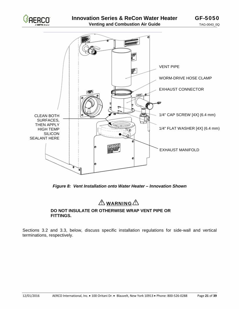
3.1. VENT INSTALLATION
NOTE Figure 8 shows how the vent system is assembled to Innovation water heaters; installation on ReCon water heaters is comparable.
1. The heaters covered in this section are design-certified as Category II and IV for venting, only
when they are installed with manufacturer specified vent system components and installation practices.
2. Install vent pipe beginning at the water heater exhaust manifold and work toward the vent cap. Start by cleaning the top surface of the exhaust manifold and the mating flange section of the duct starter piece with an alcohol swab and then apply a bead of high temperature red silicon sealant (such as Permatex Hi-Temp Red RTV or Loctite Superflex Red High Temp RTV) to that surface (see Figure 8, below).
3. Attach the exhaust connector to the exhaust manifold using the screws supplied with the kit. Use a cross-tip (Phillips) screwdriver at least 12 inches (305 mm) long. See Figure 1 (page 7) for the list of available exhaust vent connectors.
4. Vent connectors serving appliances vented by natural draft shall not be connected into any portion of mechanical draft systems operating under positive pressure
5. For Innovation and ReCon water heaters, horizontal runs shall be sloping upwards not less than 1/4 inch per foot (21 mm/m) from the heater to the vent termination.
6. The instructions for the installation of the venting system shall specify that the horizontal portions of the venting system shall be supported to prevent dips or sags where condensate could collect.
7. Rigidly support vent pipe every 5 feet (1.5 m) and at each elbow. Plumber straps may be used.
8. In a multiple unit common venting setup, to prevent internal exhaust gas recirculation when a unit is disabled/off, allow for at least 10 feet (3.1 m) of common vertical as a rule of thumb
9. Clearances and enclosures. ALL vent pipe and fittings must be installed with appropriate air space clearances to combustibles. These air space clearances apply to indoor or outdoor vents, whether they are open, enclosed, horizontal or vertical or pass through floors, walls, roofs, or framed spaces. The appropriate air space clearances should be observed between joists, studs, sub floors, plywood, drywall, or plaster enclosures, insulated sheathing, rafters, roofing, and any other combustible material. The minimum air space clearance also applies to electrical wires and any kind of building insulation.
CAUTION
Innovation Series & ReCon Water Heater GF-5050 Venting and Combustion Air Guide TAG-0043_0Q
12/01/2016 AERCO International, Inc. • 100 Oritani Dr. • Blauvelt, New York 10913 • Phone: 800-526-0288 Page 21 of 39
Figure 8: Vent Installation onto Water Heater – Innovation Shown
DO NOT INSULATE OR OTHERWISE WRAP VENT PIPE OR FITTINGS.
Sections 3.2 and 3.3, below, discuss specific installation regulations for side-wall and vertical terminations, respectively.
WARNING
VENT PIPE
WORM-DRIVE HOSE CLAMP
EXHAUST CONNECTOR
1/4" CAP SCREW [4X] (6.4 mm)
1/4" FLAT WASHER [4X] (6.4 mm)
CLEAN BOTH SURFACES,
THEN APPLY HIGH TEMP
SILICON SEALANT HERE
EXHAUST MANIFOLD
GF-5050 Innovation Series & ReCon Water Heater TAG-0043_0Q Venting and Combustion Air Guide
Page 22 of 39 AERCO International, Inc. • 100 Oritani Dr. • Blauvelt, New York 10913 • Phone: 800-526-0288 12/01/2016
3.2. INSTALLATION PROCEDURE FOR VENTING SYSTEM THROUGH A WALL The minimum distances from adjacent public walkways, adjacent buildings, operable windows and building openings shall not be less that those values specified in the National Fuel Gas Code, ANSI Z223.1 and/or CAN/CSA B149, Installation Codes. Minimum clearance of 4 feet (1.2 m) horizontally from, and in no case above or below, unless a 4-foot (1.22 m) horizontal distances is maintained, from electric meters, gas meters, regulators and relief equipment.
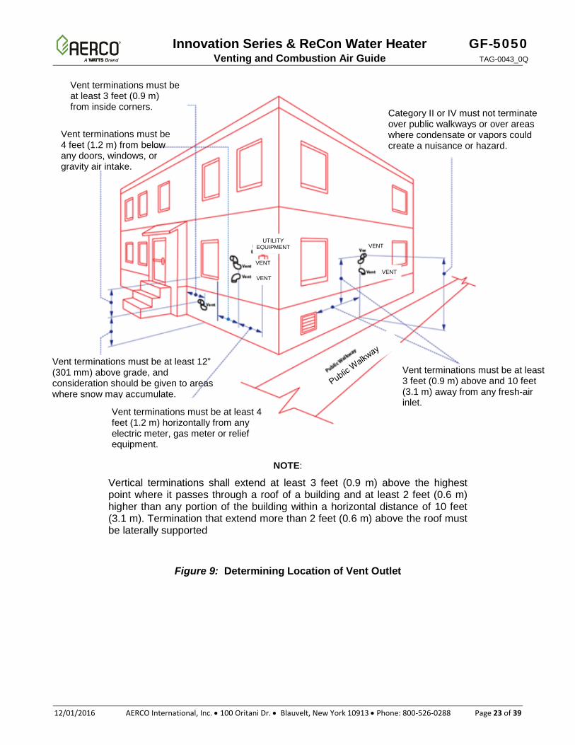
Refer to the notes below and Figure 9, when determining the location of the vent outlet.
a. At least 12 inches (30.5 cm) above finished grade, or at least 12 inches (305 mm) above the normally expected snow accumulation level in geographical areas where snow accumulates. With a vent termination clearance of at least 4 feet (1.2 m) from any air openings into a building. In Massachusetts, when side-wall venting is used, the vent termination must be located a minimum of 4 feet above grade. For detailed information pertaining to side-wall venting within the Commonwealth of Massachusetts, see pages 11 and 12 in GF-128 (Innovation) or GF-147 (ReCon).
b. At least 3 feet (0.9 m) above any forced air inlet located within 10 feet (3.1 m).
c. At least 4 feet (1.2 m) horizontally from electric meters, gas meters, regulators and relief equipment.
d. Do not terminate vent over public walkways or over an area where condensate or vapor could create a nuisance or hazard or could be detrimental to the operation of regulators, relief valves, or other equipment.
e. Do not locate the vent termination too close to shrubbery as flue products may stunt growth or kill them.
f. Some building materials may be affected by flue products expelled near unprotected surfaces. Sealing or shielding of exposed surfaces with a corrosion resistant material (such as aluminum sheet) may be required to prevent staining or deterioration.
g. See the National or Canadian Codes listed at the beginning of these instructions for additional information on termination location.
Innovation Series & ReCon Water Heater GF-5050 Venting and Combustion Air Guide TAG-0043_0Q
12/01/2016 AERCO International, Inc. • 100 Oritani Dr. • Blauvelt, New York 10913 • Phone: 800-526-0288 Page 23 of 39
NOTE:
Vertical terminations shall extend at least 3 feet (0.9 m) above the highest point where it passes through a roof of a building and at least 2 feet (0.6 m) higher than any portion of the building within a horizontal distance of 10 feet (3.1 m). Termination that extend more than 2 feet (0.6 m) above the roof must be laterally supported
Figure 9: Determining Location of Vent Outlet
Vent terminations must be at least 3 feet (0.9 m) above and 10 feet (3.1 m) away from any fresh-air inlet. Vent terminations must be at least 4
feet (1.2 m) horizontally from any electric meter, gas meter or relief equipment.
Vent terminations must be at least 3 feet (0.9 m) from inside corners.
Vent terminations must be 4 feet (1.2 m) from below any doors, windows, or gravity air intake.
Vent terminations must be at least 12” (301 mm) above grade, and consideration should be given to areas where snow may accumulate.
Category II or IV must not terminate over public walkways or over areas where condensate or vapors could create a nuisance or hazard.
VENT
VENT VENT
VENT
UTILITY EQUIPMENT
GF-5050 Innovation Series & ReCon Water Heater TAG-0043_0Q Venting and Combustion Air Guide
Page 24 of 39 AERCO International, Inc. • 100 Oritani Dr. • Blauvelt, New York 10913 • Phone: 800-526-0288 12/01/2016
3.3. INSTALLATION PROCEDURE FOR VERTICAL VENTING
DO NOT INSULATE OR OTHERWISE WRAP VENT PIPE OR FITTINGS. FOLLOW THE VENT PIPE MANUFACTURERS INSTALLATION INSTRUCTIONS FOR VERTICAL VENTING.
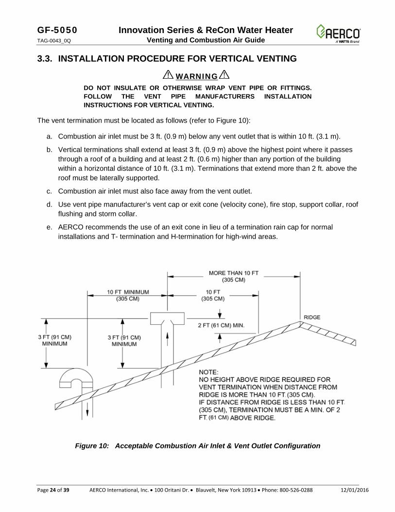
The vent termination must be located as follows (refer to Figure 10):
a. Combustion air inlet must be 3 ft. (0.9 m) below any vent outlet that is within 10 ft. (3.1 m).
b. Vertical terminations shall extend at least 3 ft. (0.9 m) above the highest point where it passes through a roof of a building and at least 2 ft. (0.6 m) higher than any portion of the building within a horizontal distance of 10 ft. (3.1 m). Terminations that extend more than 2 ft. above the roof must be laterally supported.
c. Combustion air inlet must also face away from the vent outlet.
d. Use vent pipe manufacturer’s vent cap or exit cone (velocity cone), fire stop, support collar, roof flushing and storm collar.
e. AERCO recommends the use of an exit cone in lieu of a termination rain cap for normal installations and T- termination and H-termination for high-wind areas.
Figure 10: Acceptable Combustion Air Inlet & Vent Outlet Configuration
WARNING
Innovation Series & ReCon Water Heater GF-5050 Venting and Combustion Air Guide TAG-0043_0Q
12/01/2016 AERCO International, Inc. • 100 Oritani Dr. • Blauvelt, New York 10913 • Phone: 800-526-0288 Page 25 of 39
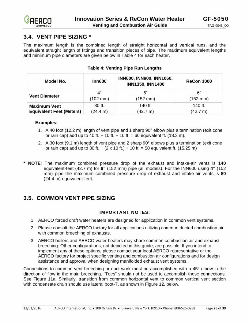
3.4. VENT PIPE SIZING * The maximum length is the combined length of straight horizontal and vertical runs, and the equivalent straight length of fittings and transition pieces of pipe. The maximum equivalent lengths and minimum pipe diameters are given below in Table 4 for each heater.
Table 4: Venting Pipe Run Lengths
Model No. Inn600 INN600, INN800, INN1060, INN1350, INN1400 ReCon 1000
Vent Diameter 4”
(102 mm) 6”
(152 mm) 6”
(152 mm)
Maximum Vent Equivalent Feet (Meters)
80 ft. (24.4 m)
140 ft. (42.7 m)
140 ft. (42.7 m)
Examples:
1. A 40 foot (12.2 m) length of vent pipe and 1 sharp 90° elbow plus a termination (exit cone or rain cap) add up to 40 ft. + 10 ft. + 10 ft. = 60 equivalent ft. (18.3 m).
2. A 30 foot (9.1 m) length of vent pipe and 2 sharp 90° elbows plus a termination (exit cone or rain cap) add up to 30 ft. + (2 x 10 ft.) + 10 ft. = 50 equivalent ft. (15.25 m)
* NOTE: The maximum combined pressure drop of the exhaust and intake-air vents is 140 equivalent-feet (42.7 m) for 6” (152 mm) pipe (all models). For the INN600 using 4” (102 mm) pipe the maximum combined pressure drop of exhaust and intake-air vents is 80 (24.4 m) equivalent-feet.
3.5. COMMON VENT PIPE SIZING
IMPORTANT NOTES:
1. AERCO forced draft water heaters are designed for application in common vent systems.
2. Please consult the AERCO factory for all applications utilizing common ducted combustion air with common breeching of exhausts.
3. AERCO boilers and AERCO water heaters may share common combustion air and exhaust breeching. Other configurations, not depicted in this guide, are possible. If you intend to implement any of these options, please contact your local AERCO representative or the AERCO factory for project specific venting and combustion air configurations and for design assistance and approval when designing manifolded exhaust vent systems.
Connections to common vent breeching or duct work must be accomplished with a 45° elbow in the direction of flow in the main breeching. “Tees” should not be used to accomplish these connections. See Figure 11a. Similarly, transition from common horizontal vent to common vertical vent section with condensate drain should use lateral boot-T, as shown in Figure 12, below.
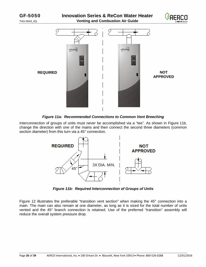
GF-5050 Innovation Series & ReCon Water Heater TAG-0043_0Q Venting and Combustion Air Guide
Page 26 of 39 AERCO International, Inc. • 100 Oritani Dr. • Blauvelt, New York 10913 • Phone: 800-526-0288 12/01/2016
Figure 11a: Recommended Connections to Common Vent Breeching Interconnection of groups of units must never be accomplished via a “tee”. As shown in Figure 11b, change the direction with one of the mains and then connect the second three diameters (common section diameter) from this turn via a 45° connection.
Figure 11b: Required Interconnection of Groups of Units
Figure 12 illustrates the preferable “transition vent section” when making the 45° connection into a main. The main can also remain at one diameter, as long as it is sized for the total number of units vented and the 45° branch connection is retained. Use of the preferred “transition” assembly will reduce the overall system pressure drop.
NOT APPROVED
REQUIRED
Innovation Series & ReCon Water Heater GF-5050 Venting and Combustion Air Guide TAG-0043_0Q
12/01/2016 AERCO International, Inc. • 100 Oritani Dr. • Blauvelt, New York 10913 • Phone: 800-526-0288 Page 27 of 39
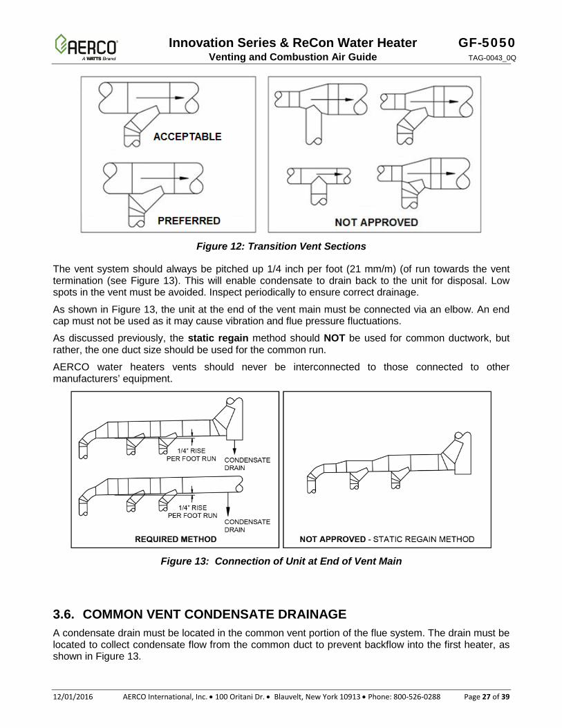
Figure 12: Transition Vent Sections
The vent system should always be pitched up 1/4 inch per foot (21 mm/m) (of run towards the vent termination (see Figure 13). This will enable condensate to drain back to the unit for disposal. Low spots in the vent must be avoided. Inspect periodically to ensure correct drainage.
As shown in Figure 13, the unit at the end of the vent main must be connected via an elbow. An end cap must not be used as it may cause vibration and flue pressure fluctuations.
As discussed previously, the static regain method should NOT be used for common ductwork, but rather, the one duct size should be used for the common run.
AERCO water heaters vents should never be interconnected to those connected to other manufacturers’ equipment.
Figure 13: Connection of Unit at End of Vent Main
3.6. COMMON VENT CONDENSATE DRAINAGE A condensate drain must be located in the common vent portion of the flue system. The drain must be located to collect condensate flow from the common duct to prevent backflow into the first heater, as shown in Figure 13.
GF-5050 Innovation Series & ReCon Water Heater TAG-0043_0Q Venting and Combustion Air Guide
Page 28 of 39 AERCO International, Inc. • 100 Oritani Dr. • Blauvelt, New York 10913 • Phone: 800-526-0288 12/01/2016
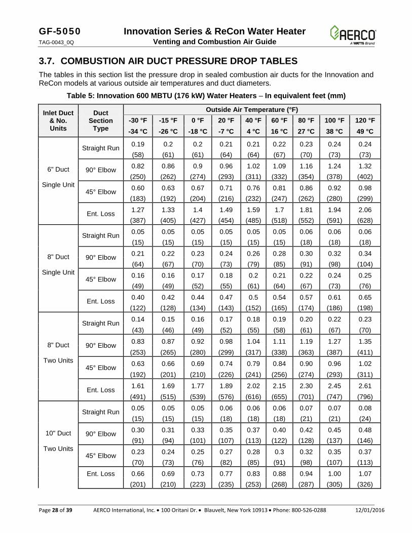
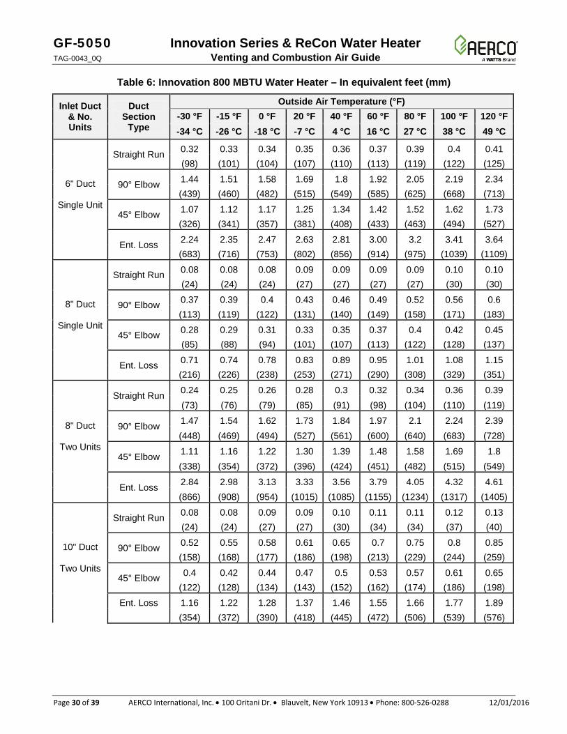
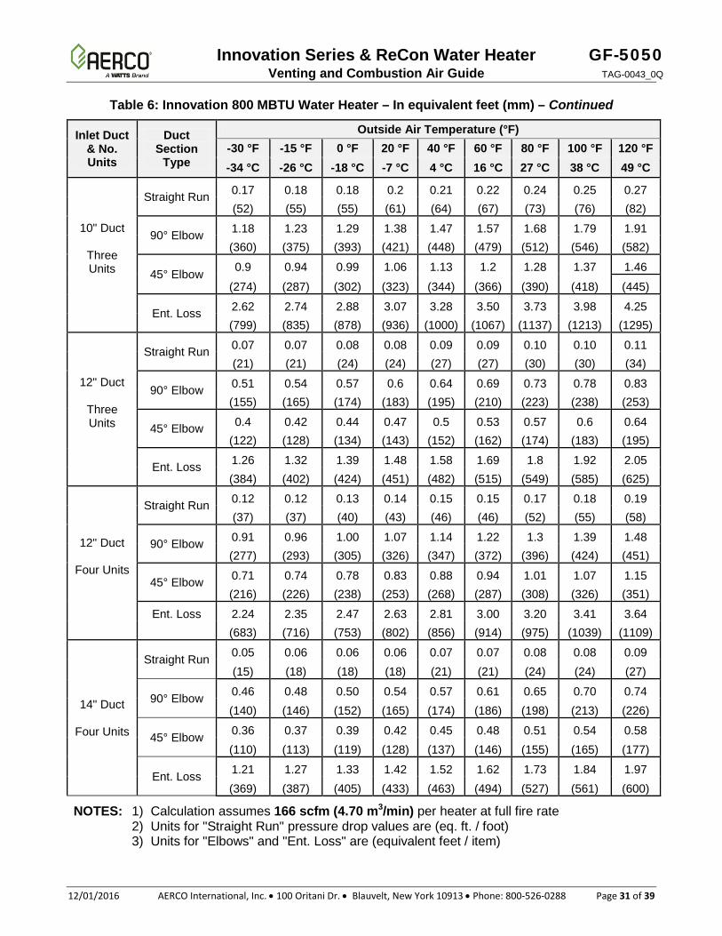
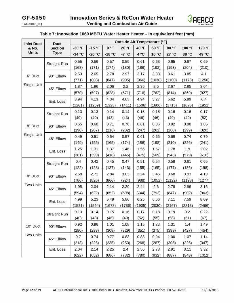
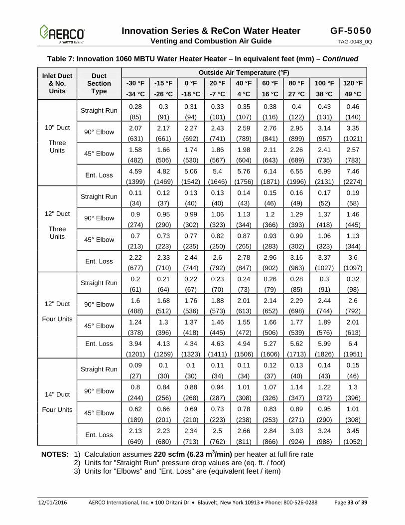
3.7. COMBUSTION AIR DUCT PRESSURE DROP TABLES The tables in this section list the pressure drop in sealed combustion air ducts for the Innovation and ReCon models at various outside air temperatures and duct diameters.
Table 5: Innovation 600 MBTU (176 kW) Water Heaters – In equivalent feet (mm)
Inlet Duct & No. Units
Duct Section
Type
Outside Air Temperature (°F) -30 °F -15 °F 0 °F 20 °F 40 °F 60 °F 80 °F 100 °F 120 °F -34 °C -26 °C -18 °C -7 °C 4 °C 16 °C 27 °C 38 °C 49 °C
6" Duct
Single Unit
Straight Run 0.19 0.2 0.2 0.21 0.21 0.22 0.23 0.24 0.24 (58) (61) (61) (64) (64) (67) (70) (73) (73)
90° Elbow 0.82 0.86 0.9 0.96 1.02 1.09 1.16 1.24 1.32 (250) (262) (274) (293) (311) (332) (354) (378) (402)
45° Elbow 0.60 0.63 0.67 0.71 0.76 0.81 0.86 0.92 0.98 (183) (192) (204) (216) (232) (247) (262) (280) (299)
Ent. Loss 1.27 1.33 1.4 1.49 1.59 1.7 1.81 1.94 2.06 (387) (405) (427) (454) (485) (518) (552) (591) (628)
8" Duct
Single Unit
Straight Run 0.05 0.05 0.05 0.05 0.05 0.05 0.06 0.06 0.06 (15) (15) (15) (15) (15) (15) (18) (18) (18)
90° Elbow 0.21 0.22 0.23 0.24 0.26 0.28 0.30 0.32 0.34 (64) (67) (70) (73) (79) (85) (91) (98) (104)
45° Elbow 0.16 0.16 0.17 0.18 0.2 0.21 0.22 0.24 0.25 (49) (49) (52) (55) (61) (64) (67) (73) (76)
Ent. Loss 0.40 0.42 0.44 0.47 0.5 0.54 0.57 0.61 0.65 (122) (128) (134) (143) (152) (165) (174) (186) (198)
8" Duct
Two Units
Straight Run 0.14 0.15 0.16 0.17 0.18 0.19 0.20 0.22 0.23 (43) (46) (49) (52) (55) (58) (61) (67) (70)
90° Elbow 0.83 0.87 0.92 0.98 1.04 1.11 1.19 1.27 1.35 (253) (265) (280) (299) (317) (338) (363) (387) (411)
45° Elbow 0.63 0.66 0.69 0.74 0.79 0.84 0.90 0.96 1.02 (192) (201) (210) (226) (241) (256) (274) (293) (311)
Ent. Loss 1.61 1.69 1.77 1.89 2.02 2.15 2.30 2.45 2.61 (491) (515) (539) (576) (616) (655) (701) (747) (796)
10" Duct
Two Units
Straight Run 0.05 0.05 0.05 0.06 0.06 0.06 0.07 0.07 0.08 (15) (15) (15) (18) (18) (18) (21) (21) (24)
90° Elbow 0.30 0.31 0.33 0.35 0.37 0.40 0.42 0.45 0.48 (91) (94) (101) (107) (113) (122) (128) (137) (146)
45° Elbow 0.23 0.24 0.25 0.27 0.28 0.3 0.32 0.35 0.37 (70) (73) (76) (82) (85) (91) (98) (107) (113)
Ent. Loss
0.66 0.69 0.73 0.77 0.83 0.88 0.94 1.00 1.07 (201) (210) (223) (235) (253) (268) (287) (305) (326)

Innovation Series & ReCon Water Heater GF-5050 Venting and Combustion Air Guide TAG-0043_0Q
12/01/2016 AERCO International, Inc. • 100 Oritani Dr. • Blauvelt, New York 10913 • Phone: 800-526-0288 Page 29 of 39
Table 5: Innovation 600 MBTU (176 kW) Water Heaters – In equivalent feet (mm) – Continued
Inlet Duct & No. Units
Duct Section
Type
Outside Air Temperature (°F) -30 °F -15 °F 0 °F 20 °F 40 °F 60 °F 80 °F 100 °F 120 °F -34 °C -26 °C -18 °C -7 °C 4 °C 16 °C 27 °C 38 °C 49 °C
10" Duct
Three Units
Straight Run 0.10 0.1 0.11 0.12 0.12 0.13 0.14 0.15 0.16 (30) (30) (34) (37) (37) (40) (43) (46) (49)
90° Elbow 0.67 0.7 0.73 0.78 0.84 0.89 0.95 1.01 1.08 (204) (213) (223) (238) (256) (271) (290) (308) (329)
45° Elbow 0.51 0.54 0.56 0.6 0.64 0.68 0.73 0.78 0.83 (155) (165) (171) (183) (195) (207) (223) (238) (253)
Ent. Loss 1.48 1.56 1.63 1.74 1.86 1.98 2.12 2.26 2.41 (451) (475) (497) (530) (567) (604) (646) (689) (735)
12" Duct
Three Units
Straight Run 0.04 0.04 0.04 0.05 0.05 0.05 0.06 0.06 0.07 (12) (12) (12) (15) (15) (15) (18) (18) (21)
90° Elbow 0.29 0.31 0.32 0.34 0.36 0.39 0.42 0.44 0.47 (88) (94) (98) (104) (110) (119) (128) (134) (143)
45° Elbow 0.23 0.24 0.25 0.26 0.28 0.3 0.32 0.34 0.37 (70) (73) (76) (79) (85) (91) (98) (104) (113)
Ent. Loss 0.72 0.75 0.79 0.84 0.9 0.96 1.02 1.09 1.16 (219) (229) (241) (256) (274) (293) (311) (332) (354)
12" Duct
Four Units
Straight Run 0.07 0.07 0.08 0.08 0.09 0.09 0.10 0.10 0.11 (21) (21) (24) (24) (27) (27) (30) (30) (34)
90° Elbow 0.52 0.54 0.57 0.61 0.65 0.69 0.74 0.79 0.84 (158) (165) (174) (186) (198) (210) (226) (241) (256)
45° Elbow 0.4 0.42 0.44 0.47 0.5 0.53 0.57 0.61 0.65 (122) (128) (134) (143) (152) (162) (174) (186) (198)
Ent. Loss
1.27 1.33 1.4 1.49 1.59 1.7 1.81 1.94 2.06 (387) (405) (427) (454) (485) (518) (552) (591) (628)
14" Duct
Four Units
Straight Run 0.03 0.03 0.04 0.04 0.04 0.04 0.05 0.05 0.05 (9) (9) (12) (12) (12) (12) (15) (15) (15)
90° Elbow 0.26 0.27 0.29 0.3 0.32 0.35 0.37 0.39 0.42 (79) (82) (88) (91) (98) (107) (113) (119) (128)
45° Elbow 0.20 0.21 0.22 0.24 0.25 0.27 0.29 0.31 0.33 (61) (64) (67) (73) (76) (82) (88) (94) (101)
Ent. Loss 0.69 0.72 0.76 0.81 0.86 0.92 0.98 1.04 1.11 (210) (219) (232) (247) (262) (280) (299) (317) (338)
NOTES: 1) Calculation assumes 125 scfm (3.54 m3/min) per heater at full fire rate 2) Units for "Straight Run" pressure drop values are (eq. ft. / foot) 3) Units for "Elbows" and "Ent. Loss" are (equivalent feet / item)
GF-5050 Innovation Series & ReCon Water Heater TAG-0043_0Q Venting and Combustion Air Guide
Page 30 of 39 AERCO International, Inc. • 100 Oritani Dr. • Blauvelt, New York 10913 • Phone: 800-526-0288 12/01/2016
Table 6: Innovation 800 MBTU Water Heater – In equivalent feet (mm)
Inlet Duct & No. Units
Duct Section
Type
Outside Air Temperature (°F) -30 °F -15 °F 0 °F 20 °F 40 °F 60 °F 80 °F 100 °F 120 °F -34 °C -26 °C -18 °C -7 °C 4 °C 16 °C 27 °C 38 °C 49 °C
6" Duct
Single Unit
Straight Run 0.32 0.33 0.34 0.35 0.36 0.37 0.39 0.4 0.41 (98) (101) (104) (107) (110) (113) (119) (122) (125)
90° Elbow 1.44 1.51 1.58 1.69 1.8 1.92 2.05 2.19 2.34 (439) (460) (482) (515) (549) (585) (625) (668) (713)
45° Elbow 1.07 1.12 1.17 1.25 1.34 1.42 1.52 1.62 1.73 (326) (341) (357) (381) (408) (433) (463) (494) (527)
Ent. Loss 2.24 2.35 2.47 2.63 2.81 3.00 3.2 3.41 3.64 (683) (716) (753) (802) (856) (914) (975) (1039) (1109)
8" Duct
Single Unit
Straight Run 0.08 0.08 0.08 0.09 0.09 0.09 0.09 0.10 0.10 (24) (24) (24) (27) (27) (27) (27) (30) (30)
90° Elbow 0.37 0.39 0.4 0.43 0.46 0.49 0.52 0.56 0.6 (113) (119) (122) (131) (140) (149) (158) (171) (183)
45° Elbow 0.28 0.29 0.31 0.33 0.35 0.37 0.4 0.42 0.45 (85) (88) (94) (101) (107) (113) (122) (128) (137)
Ent. Loss 0.71 0.74 0.78 0.83 0.89 0.95 1.01 1.08 1.15 (216) (226) (238) (253) (271) (290) (308) (329) (351)
8" Duct
Two Units
Straight Run 0.24 0.25 0.26 0.28 0.3 0.32 0.34 0.36 0.39 (73) (76) (79) (85) (91) (98) (104) (110) (119)
90° Elbow 1.47 1.54 1.62 1.73 1.84 1.97 2.1 2.24 2.39 (448) (469) (494) (527) (561) (600) (640) (683) (728)
45° Elbow 1.11 1.16 1.22 1.30 1.39 1.48 1.58 1.69 1.8 (338) (354) (372) (396) (424) (451) (482) (515) (549)
Ent. Loss 2.84 2.98 3.13 3.33 3.56 3.79 4.05 4.32 4.61 (866) (908) (954) (1015) (1085) (1155) (1234) (1317) (1405)
10" Duct
Two Units
Straight Run 0.08 0.08 0.09 0.09 0.10 0.11 0.11 0.12 0.13 (24) (24) (27) (27) (30) (34) (34) (37) (40)
90° Elbow 0.52 0.55 0.58 0.61 0.65 0.7 0.75 0.8 0.85 (158) (168) (177) (186) (198) (213) (229) (244) (259)
45° Elbow 0.4 0.42 0.44 0.47 0.5 0.53 0.57 0.61 0.65 (122) (128) (134) (143) (152) (162) (174) (186) (198)
Ent. Loss
1.16 1.22 1.28 1.37 1.46 1.55 1.66 1.77 1.89 (354) (372) (390) (418) (445) (472) (506) (539) (576)
Innovation Series & ReCon Water Heater GF-5050 Venting and Combustion Air Guide TAG-0043_0Q
12/01/2016 AERCO International, Inc. • 100 Oritani Dr. • Blauvelt, New York 10913 • Phone: 800-526-0288 Page 31 of 39
Table 6: Innovation 800 MBTU Water Heater – In equivalent feet (mm) – Continued
Inlet Duct & No. Units
Duct Section
Type
Outside Air Temperature (°F) -30 °F -15 °F 0 °F 20 °F 40 °F 60 °F 80 °F 100 °F 120 °F -34 °C -26 °C -18 °C -7 °C 4 °C 16 °C 27 °C 38 °C 49 °C
10" Duct
Three Units
Straight Run 0.17 0.18 0.18 0.2 0.21 0.22 0.24 0.25 0.27 (52) (55) (55) (61) (64) (67) (73) (76) (82)
90° Elbow 1.18 1.23 1.29 1.38 1.47 1.57 1.68 1.79 1.91 (360) (375) (393) (421) (448) (479) (512) (546) (582)
45° Elbow 0.9 0.94 0.99 1.06 1.13 1.2 1.28 1.37 1.46
(274) (287) (302) (323) (344) (366) (390) (418) (445)
Ent. Loss 2.62 2.74 2.88 3.07 3.28 3.50 3.73 3.98 4.25 (799) (835) (878) (936) (1000) (1067) (1137) (1213) (1295)
12" Duct
Three Units
Straight Run 0.07 0.07 0.08 0.08 0.09 0.09 0.10 0.10 0.11 (21) (21) (24) (24) (27) (27) (30) (30) (34)
90° Elbow 0.51 0.54 0.57 0.6 0.64 0.69 0.73 0.78 0.83 (155) (165) (174) (183) (195) (210) (223) (238) (253)
45° Elbow 0.4 0.42 0.44 0.47 0.5 0.53 0.57 0.6 0.64 (122) (128) (134) (143) (152) (162) (174) (183) (195)
Ent. Loss 1.26 1.32 1.39 1.48 1.58 1.69 1.8 1.92 2.05 (384) (402) (424) (451) (482) (515) (549) (585) (625)
12" Duct
Four Units
Straight Run 0.12 0.12 0.13 0.14 0.15 0.15 0.17 0.18 0.19 (37) (37) (40) (43) (46) (46) (52) (55) (58)
90° Elbow 0.91 0.96 1.00 1.07 1.14 1.22 1.3 1.39 1.48 (277) (293) (305) (326) (347) (372) (396) (424) (451)
45° Elbow 0.71 0.74 0.78 0.83 0.88 0.94 1.01 1.07 1.15 (216) (226) (238) (253) (268) (287) (308) (326) (351)
Ent. Loss
2.24 2.35 2.47 2.63 2.81 3.00 3.20 3.41 3.64 (683) (716) (753) (802) (856) (914) (975) (1039) (1109)
14" Duct
Four Units
Straight Run 0.05 0.06 0.06 0.06 0.07 0.07 0.08 0.08 0.09 (15) (18) (18) (18) (21) (21) (24) (24) (27)
90° Elbow 0.46 0.48 0.50 0.54 0.57 0.61 0.65 0.70 0.74 (140) (146) (152) (165) (174) (186) (198) (213) (226)
45° Elbow 0.36 0.37 0.39 0.42 0.45 0.48 0.51 0.54 0.58 (110) (113) (119) (128) (137) (146) (155) (165) (177)
Ent. Loss 1.21 1.27 1.33 1.42 1.52 1.62 1.73 1.84 1.97 (369) (387) (405) (433) (463) (494) (527) (561) (600)
NOTES: 1) Calculation assumes 166 scfm (4.70 m3/min) per heater at full fire rate 2) Units for "Straight Run" pressure drop values are (eq. ft. / foot) 3) Units for "Elbows" and "Ent. Loss" are (equivalent feet / item)
GF-5050 Innovation Series & ReCon Water Heater TAG-0043_0Q Venting and Combustion Air Guide
Page 32 of 39 AERCO International, Inc. • 100 Oritani Dr. • Blauvelt, New York 10913 • Phone: 800-526-0288 12/01/2016
Table 7: Innovation 1060 MBTU Water Heater Heater – In equivalent feet (mm)
Inlet Duct & No. Units
Duct Section
Type
Outside Air Temperature (°F) -30 °F -15 °F 0 °F 20 °F 40 °F 60 °F 80 °F 100 °F 120 °F -34 °C -26 °C -18 °C -7 °C 4 °C 16 °C 27 °C 38 °C 49 °C
6" Duct
Single Unit
Straight Run 0.55 0.56 0.57 0.59 0.61 0.63 0.65 0.67 0.69 (168) (171) (174) (180) (186) (192) (198) (204) (210)
90° Elbow 2.53 2.65 2.78 2.97 3.17 3.38 3.61 3.85 4.1 (771) (808) (847) (905) (966) (1030) (1100) (1173) (1250)
45° Elbow 1.87 1.96 2.06 2.2 2.35 2.5 2.67 2.85 3.04
(570) (597) (628) (671) (716) (762) (814) (869) (927)
Ent. Loss 3.94 4.13 4.34 4.63 4.94 5.27 5.62 5.99 6.4 (1201) (1259) (1323) (1411) (1506) (1606) (1713) (1826) (1951)
8" Duct
Single Unit
Straight Run 0.13 0.13 0.14 0.14 0.15 0.15 0.16 0.16 0.17 (40) (40) (43) (43) (46) (46) (49) (49) (52)
90° Elbow 0.65 0.68 0.71 0.76 0.81 0.86 0.92 0.98 1.05 (198) (207) (216) (232) (247) (262) (280) (299) (320)
45° Elbow 0.49 0.51 0.54 0.57 0.61 0.65 0.69 0.74 0.79 (149) (155) (165) (174) (186) (198) (210) (226) (241)
Ent. Loss 1.25 1.31 1.37 1.46 1.56 1.67 1.78 1.9 2.02 (381) (399) (418) (445) (475) (509) (543) (579) (616)
8" Duct
Two Units
Straight Run 0.4 0.42 0.45 0.47 0.51 0.54 0.58 0.61 0.65 (122) (128) (137) (143) (155) (165) (177) (186) (198)
90° Elbow 2.58 2.71 2.84 3.03 3.24 3.45 3.68 3.93 4.19 (786) (826) (866) (924) (988) (1052) (1122) (1198) (1277)
45° Elbow 1.95 2.04 2.14 2.29 2.44 2.6 2.78 2.96 3.16 (594) (622) (652) (698) (744) (792) (847) (902) (963)
Ent. Loss 4.99 5.23 5.49 5.86 6.25 6.66 7.11 7.59 8.09 (1521) (1594) (1673) (1786) (1905) (2030) (2167) (2313) (2466)
10" Duct
Two Units
Straight Run 0.13 0.14 0.15 0.16 0.17 0.18 0.19 0.2 0.22 (40) (43) (46) (49) (52) (55) (58) (61) (67)
90° Elbow 0.92 0.96 1.01 1.08 1.15 1.23 1.31 1.4 1.49 (280) (293) (308) (329) (351) (375) (399) (427) (454)
45° Elbow 0.7 0.74 0.77 0.83 0.88 0.94 1.00 1.07 1.14 (213) (226) (235) (253) (268) (287) (305) (326) (347)
Ent. Loss
2.04 2.14 2.25 2.4 2.56 2.73 2.91 3.11 3.32 (622) (652) (686) (732) (780) (832) (887) (948) (1012)
Innovation Series & ReCon Water Heater GF-5050 Venting and Combustion Air Guide TAG-0043_0Q
12/01/2016 AERCO International, Inc. • 100 Oritani Dr. • Blauvelt, New York 10913 • Phone: 800-526-0288 Page 33 of 39
Table 7: Innovation 1060 MBTU Water Heater Heater – In equivalent feet (mm) – Continued
Inlet Duct & No. Units
Duct Section
Type
Outside Air Temperature (°F) -30 °F -15 °F 0 °F 20 °F 40 °F 60 °F 80 °F 100 °F 120 °F -34 °C -26 °C -18 °C -7 °C 4 °C 16 °C 27 °C 38 °C 49 °C
10" Duct
Three Units
Straight Run 0.28 0.3 0.31 0.33 0.35 0.38 0.4 0.43 0.46 (85) (91) (94) (101) (107) (116) (122) (131) (140)
90° Elbow 2.07 2.17 2.27 2.43 2.59 2.76 2.95 3.14 3.35 (631) (661) (692) (741) (789) (841) (899) (957) (1021)
45° Elbow 1.58 1.66 1.74 1.86 1.98 2.11 2.26 2.41 2.57 (482) (506) (530) (567) (604) (643) (689) (735) (783)
Ent. Loss 4.59 4.82 5.06 5.4 5.76 6.14 6.55 6.99 7.46 (1399) (1469) (1542) (1646) (1756) (1871) (1996) (2131) (2274)
12" Duct
Three Units
Straight Run 0.11 0.12 0.13 0.13 0.14 0.15 0.16 0.17 0.19 (34) (37) (40) (40) (43) (46) (49) (52) (58)
90° Elbow 0.9 0.95 0.99 1.06 1.13 1.2 1.29 1.37 1.46 (274) (290) (302) (323) (344) (366) (393) (418) (445)
45° Elbow 0.7 0.73 0.77 0.82 0.87 0.93 0.99 1.06 1.13 (213) (223) (235) (250) (265) (283) (302) (323) (344)
Ent. Loss 2.22 2.33 2.44 2.6 2.78 2.96 3.16 3.37 3.6 (677) (710) (744) (792) (847) (902) (963) (1027) (1097)
12" Duct
Four Units
Straight Run 0.2 0.21 0.22 0.23 0.24 0.26 0.28 0.3 0.32 (61) (64) (67) (70) (73) (79) (85) (91) (98)
90° Elbow 1.6 1.68 1.76 1.88 2.01 2.14 2.29 2.44 2.6 (488) (512) (536) (573) (613) (652) (698) (744) (792)
45° Elbow 1.24 1.3 1.37 1.46 1.55 1.66 1.77 1.89 2.01 (378) (396) (418) (445) (472) (506) (539) (576) (613)
Ent. Loss
3.94 4.13 4.34 4.63 4.94 5.27 5.62 5.99 6.4 (1201) (1259) (1323) (1411) (1506) (1606) (1713) (1826) (1951)
14" Duct
Four Units
Straight Run 0.09 0.1 0.1 0.11 0.11 0.12 0.13 0.14 0.15 (27) (30) (30) (34) (34) (37) (40) (43) (46)
90° Elbow 0.8 0.84 0.88 0.94 1.01 1.07 1.14 1.22 1.3 (244) (256) (268) (287) (308) (326) (347) (372) (396)
45° Elbow 0.62 0.66 0.69 0.73 0.78 0.83 0.89 0.95 1.01 (189) (201) (210) (223) (238) (253) (271) (290) (308)
Ent. Loss 2.13 2.23 2.34 2.5 2.66 2.84 3.03 3.24 3.45 (649) (680) (713) (762) (811) (866) (924) (988) (1052)
NOTES: 1) Calculation assumes 220 scfm (6.23 m3/min) per heater at full fire rate 2) Units for "Straight Run" pressure drop values are (eq. ft. / foot) 3) Units for "Elbows" and "Ent. Loss" are (equivalent feet / item)
GF-5050 Innovation Series & ReCon Water Heater TAG-0043_0Q Venting and Combustion Air Guide
Page 34 of 39 AERCO International, Inc. • 100 Oritani Dr. • Blauvelt, New York 10913 • Phone: 800-526-0288 12/01/2016
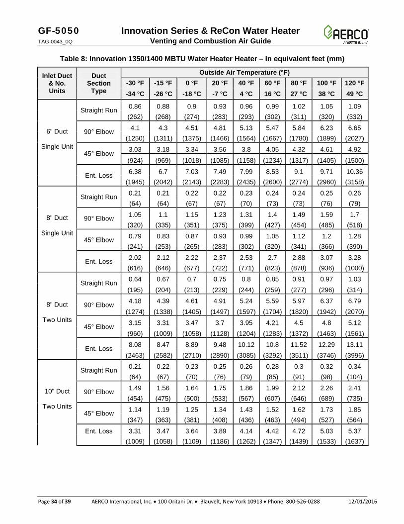
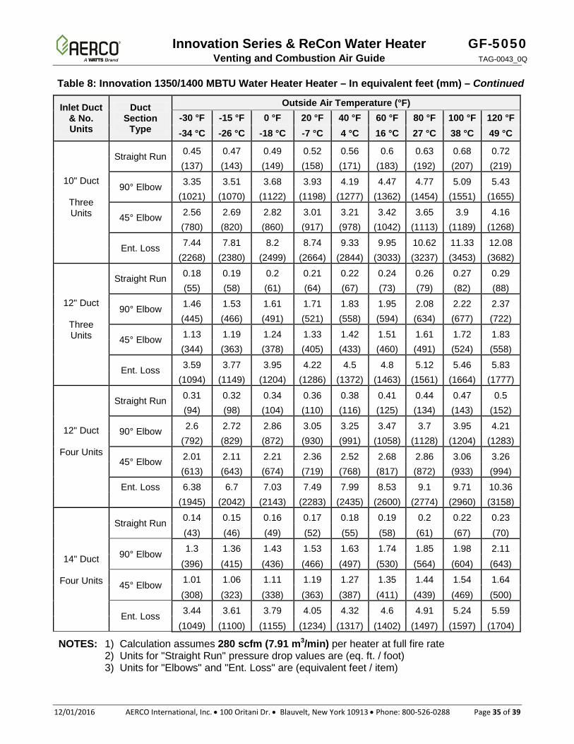
Table 8: Innovation 1350/1400 MBTU Water Heater Heater – In equivalent feet (mm)
Inlet Duct & No. Units
Duct Section
Type
Outside Air Temperature (°F) -30 °F -15 °F 0 °F 20 °F 40 °F 60 °F 80 °F 100 °F 120 °F -34 °C -26 °C -18 °C -7 °C 4 °C 16 °C 27 °C 38 °C 49 °C
6" Duct
Single Unit
Straight Run 0.86 0.88 0.9 0.93 0.96 0.99 1.02 1.05 1.09 (262) (268) (274) (283) (293) (302) (311) (320) (332)
90° Elbow 4.1 4.3 4.51 4.81 5.13 5.47 5.84 6.23 6.65 (1250) (1311) (1375) (1466) (1564) (1667) (1780) (1899) (2027)
45° Elbow 3.03 3.18 3.34 3.56 3.8 4.05 4.32 4.61 4.92
(924) (969) (1018) (1085) (1158) (1234) (1317) (1405) (1500)
Ent. Loss 6.38 6.7 7.03 7.49 7.99 8.53 9.1 9.71 10.36 (1945) (2042) (2143) (2283) (2435) (2600) (2774) (2960) (3158)
8" Duct
Single Unit
Straight Run 0.21 0.21 0.22 0.22 0.23 0.24 0.24 0.25 0.26 (64) (64) (67) (67) (70) (73) (73) (76) (79)
90° Elbow 1.05 1.1 1.15 1.23 1.31 1.4 1.49 1.59 1.7 (320) (335) (351) (375) (399) (427) (454) (485) (518)
45° Elbow 0.79 0.83 0.87 0.93 0.99 1.05 1.12 1.2 1.28 (241) (253) (265) (283) (302) (320) (341) (366) (390)
Ent. Loss 2.02 2.12 2.22 2.37 2.53 2.7 2.88 3.07 3.28 (616) (646) (677) (722) (771) (823) (878) (936) (1000)
8" Duct
Two Units
Straight Run 0.64 0.67 0.7 0.75 0.8 0.85 0.91 0.97 1.03 (195) (204) (213) (229) (244) (259) (277) (296) (314)
90° Elbow 4.18 4.39 4.61 4.91 5.24 5.59 5.97 6.37 6.79 (1274) (1338) (1405) (1497) (1597) (1704) (1820) (1942) (2070)
45° Elbow 3.15 3.31 3.47 3.7 3.95 4.21 4.5 4.8 5.12 (960) (1009) (1058) (1128) (1204) (1283) (1372) (1463) (1561)
Ent. Loss 8.08 8.47 8.89 9.48 10.12 10.8 11.52 12.29 13.11 (2463) (2582) (2710) (2890) (3085) (3292) (3511) (3746) (3996)
10" Duct
Two Units
Straight Run 0.21 0.22 0.23 0.25 0.26 0.28 0.3 0.32 0.34 (64) (67) (70) (76) (79) (85) (91) (98) (104)
90° Elbow 1.49 1.56 1.64 1.75 1.86 1.99 2.12 2.26 2.41 (454) (475) (500) (533) (567) (607) (646) (689) (735)
45° Elbow 1.14 1.19 1.25 1.34 1.43 1.52 1.62 1.73 1.85 (347) (363) (381) (408) (436) (463) (494) (527) (564)
Ent. Loss
3.31 3.47 3.64 3.89 4.14 4.42 4.72 5.03 5.37 (1009) (1058) (1109) (1186) (1262) (1347) (1439) (1533) (1637)
Innovation Series & ReCon Water Heater GF-5050 Venting and Combustion Air Guide TAG-0043_0Q
12/01/2016 AERCO International, Inc. • 100 Oritani Dr. • Blauvelt, New York 10913 • Phone: 800-526-0288 Page 35 of 39
Table 8: Innovation 1350/1400 MBTU Water Heater Heater – In equivalent feet (mm) – Continued
Inlet Duct & No. Units
Duct Section
Type
Outside Air Temperature (°F) -30 °F -15 °F 0 °F 20 °F 40 °F 60 °F 80 °F 100 °F 120 °F -34 °C -26 °C -18 °C -7 °C 4 °C 16 °C 27 °C 38 °C 49 °C
10" Duct
Three Units
Straight Run 0.45 0.47 0.49 0.52 0.56 0.6 0.63 0.68 0.72 (137) (143) (149) (158) (171) (183) (192) (207) (219)
90° Elbow 3.35 3.51 3.68 3.93 4.19 4.47 4.77 5.09 5.43 (1021) (1070) (1122) (1198) (1277) (1362) (1454) (1551) (1655)
45° Elbow 2.56 2.69 2.82 3.01 3.21 3.42 3.65 3.9 4.16 (780) (820) (860) (917) (978) (1042) (1113) (1189) (1268)
Ent. Loss 7.44 7.81 8.2 8.74 9.33 9.95 10.62 11.33 12.08 (2268) (2380) (2499) (2664) (2844) (3033) (3237) (3453) (3682)
12" Duct
Three Units
Straight Run 0.18 0.19 0.2 0.21 0.22 0.24 0.26 0.27 0.29 (55) (58) (61) (64) (67) (73) (79) (82) (88)
90° Elbow 1.46 1.53 1.61 1.71 1.83 1.95 2.08 2.22 2.37 (445) (466) (491) (521) (558) (594) (634) (677) (722)
45° Elbow 1.13 1.19 1.24 1.33 1.42 1.51 1.61 1.72 1.83 (344) (363) (378) (405) (433) (460) (491) (524) (558)
Ent. Loss 3.59 3.77 3.95 4.22 4.5 4.8 5.12 5.46 5.83 (1094) (1149) (1204) (1286) (1372) (1463) (1561) (1664) (1777)
12" Duct
Four Units
Straight Run 0.31 0.32 0.34 0.36 0.38 0.41 0.44 0.47 0.5 (94) (98) (104) (110) (116) (125) (134) (143) (152)
90° Elbow 2.6 2.72 2.86 3.05 3.25 3.47 3.7 3.95 4.21 (792) (829) (872) (930) (991) (1058) (1128) (1204) (1283)
45° Elbow 2.01 2.11 2.21 2.36 2.52 2.68 2.86 3.06 3.26 (613) (643) (674) (719) (768) (817) (872) (933) (994)
Ent. Loss
6.38 6.7 7.03 7.49 7.99 8.53 9.1 9.71 10.36 (1945) (2042) (2143) (2283) (2435) (2600) (2774) (2960) (3158)
14" Duct
Four Units
Straight Run 0.14 0.15 0.16 0.17 0.18 0.19 0.2 0.22 0.23 (43) (46) (49) (52) (55) (58) (61) (67) (70)
90° Elbow 1.3 1.36 1.43 1.53 1.63 1.74 1.85 1.98 2.11 (396) (415) (436) (466) (497) (530) (564) (604) (643)
45° Elbow 1.01 1.06 1.11 1.19 1.27 1.35 1.44 1.54 1.64 (308) (323) (338) (363) (387) (411) (439) (469) (500)
Ent. Loss 3.44 3.61 3.79 4.05 4.32 4.6 4.91 5.24 5.59 (1049) (1100) (1155) (1234) (1317) (1402) (1497) (1597) (1704)
NOTES: 1) Calculation assumes 280 scfm (7.91 m3/min) per heater at full fire rate 2) Units for "Straight Run" pressure drop values are (eq. ft. / foot) 3) Units for "Elbows" and "Ent. Loss" are (equivalent feet / item)
GF-5050 Innovation Series & ReCon Water Heater TAG-0043_0Q Venting and Combustion Air Guide
Page 36 of 39 AERCO International, Inc. • 100 Oritani Dr. • Blauvelt, New York 10913 • Phone: 800-526-0288 12/01/2016
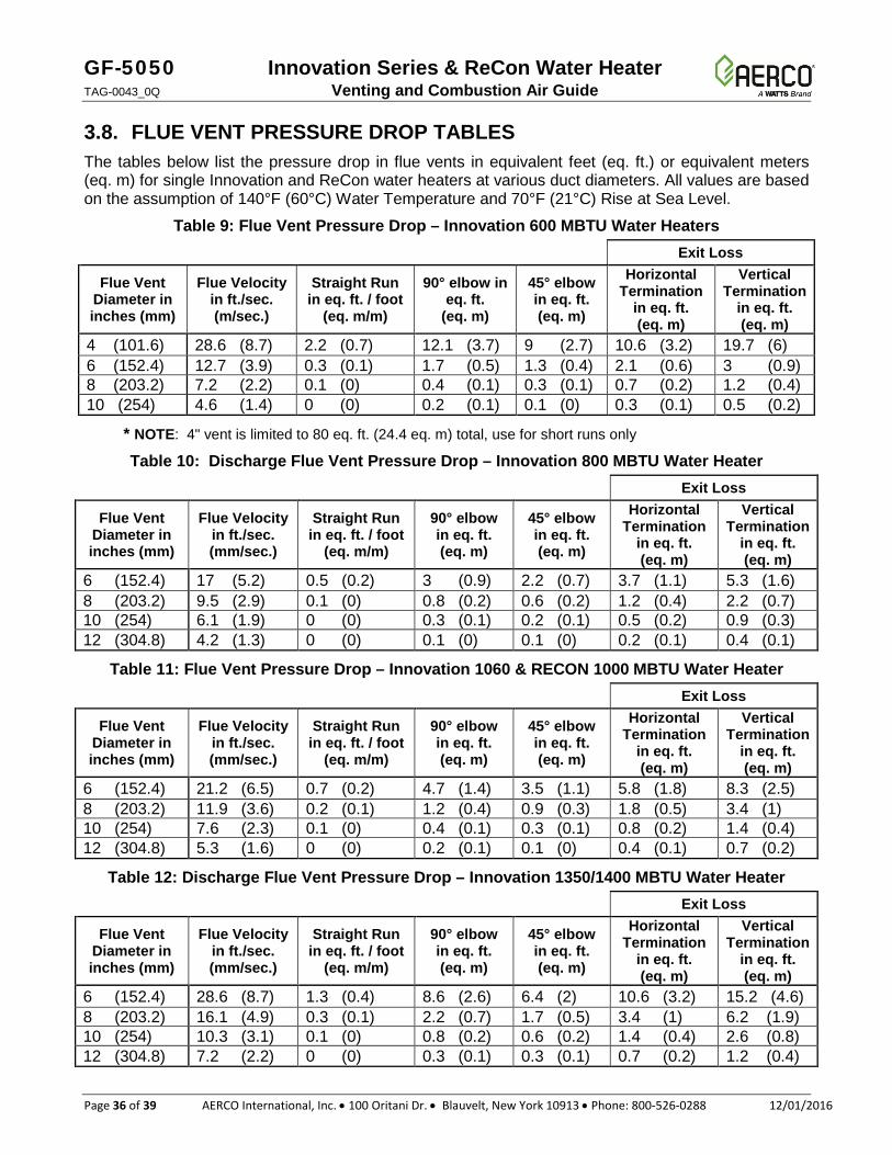
3.8. FLUE VENT PRESSURE DROP TABLES The tables below list the pressure drop in flue vents in equivalent feet (eq. ft.) or equivalent meters (eq. m) for single Innovation and ReCon water heaters at various duct diameters. All values are based on the assumption of 140°F (60°C) Water Temperature and 70°F (21°C) Rise at Sea Level.
Table 9: Flue Vent Pressure Drop – Innovation 600 MBTU Water Heaters Exit Loss
Flue Vent Diameter in inches (mm)
Flue Velocity in ft./sec. (m/sec.)
Straight Run in eq. ft. / foot
(eq. m/m)
90° elbow in eq. ft.
(eq. m)
45° elbow in eq. ft. (eq. m)
Horizontal Termination
in eq. ft. (eq. m)
Vertical Termination
in eq. ft. (eq. m)
4 (101.6) 28.6 (8.7) 2.2 (0.7) 12.1 (3.7) 9 (2.7) 10.6 (3.2) 19.7 (6) 6 (152.4) 12.7 (3.9) 0.3 (0.1) 1.7 (0.5) 1.3 (0.4) 2.1 (0.6) 3 (0.9) 8 (203.2) 7.2 (2.2) 0.1 (0) 0.4 (0.1) 0.3 (0.1) 0.7 (0.2) 1.2 (0.4) 10 (254) 4.6 (1.4) 0 (0) 0.2 (0.1) 0.1 (0) 0.3 (0.1) 0.5 (0.2)
* NOTE: 4" vent is limited to 80 eq. ft. (24.4 eq. m) total, use for short runs only
Table 10: Discharge Flue Vent Pressure Drop – Innovation 800 MBTU Water Heater Exit Loss
Flue Vent Diameter in inches (mm)
Flue Velocity in ft./sec. (mm/sec.)
Straight Run in eq. ft. / foot
(eq. m/m)
90° elbow in eq. ft. (eq. m)
45° elbow in eq. ft. (eq. m)
Horizontal Termination
in eq. ft. (eq. m)
Vertical Termination
in eq. ft. (eq. m)
6 (152.4) 17 (5.2) 0.5 (0.2) 3 (0.9) 2.2 (0.7) 3.7 (1.1) 5.3 (1.6) 8 (203.2) 9.5 (2.9) 0.1 (0) 0.8 (0.2) 0.6 (0.2) 1.2 (0.4) 2.2 (0.7) 10 (254) 6.1 (1.9) 0 (0) 0.3 (0.1) 0.2 (0.1) 0.5 (0.2) 0.9 (0.3) 12 (304.8) 4.2 (1.3) 0 (0) 0.1 (0) 0.1 (0) 0.2 (0.1) 0.4 (0.1)
Table 11: Flue Vent Pressure Drop – Innovation 1060 & RECON 1000 MBTU Water Heater Exit Loss
Flue Vent Diameter in inches (mm)
Flue Velocity in ft./sec. (mm/sec.)
Straight Run in eq. ft. / foot
(eq. m/m)
90° elbow in eq. ft. (eq. m)
45° elbow in eq. ft. (eq. m)
Horizontal Termination
in eq. ft. (eq. m)
Vertical Termination
in eq. ft. (eq. m)
6 (152.4) 21.2 (6.5) 0.7 (0.2) 4.7 (1.4) 3.5 (1.1) 5.8 (1.8) 8.3 (2.5) 8 (203.2) 11.9 (3.6) 0.2 (0.1) 1.2 (0.4) 0.9 (0.3) 1.8 (0.5) 3.4 (1) 10 (254) 7.6 (2.3) 0.1 (0) 0.4 (0.1) 0.3 (0.1) 0.8 (0.2) 1.4 (0.4) 12 (304.8) 5.3 (1.6) 0 (0) 0.2 (0.1) 0.1 (0) 0.4 (0.1) 0.7 (0.2)
Table 12: Discharge Flue Vent Pressure Drop – Innovation 1350/1400 MBTU Water Heater Exit Loss
Flue Vent Diameter in inches (mm)
Flue Velocity in ft./sec. (mm/sec.)
Straight Run in eq. ft. / foot
(eq. m/m)
90° elbow in eq. ft. (eq. m)
45° elbow in eq. ft. (eq. m)
Horizontal Termination
in eq. ft. (eq. m)
Vertical Termination
in eq. ft. (eq. m)
6 (152.4) 28.6 (8.7) 1.3 (0.4) 8.6 (2.6) 6.4 (2) 10.6 (3.2) 15.2 (4.6) 8 (203.2) 16.1 (4.9) 0.3 (0.1) 2.2 (0.7) 1.7 (0.5) 3.4 (1) 6.2 (1.9) 10 (254) 10.3 (3.1) 0.1 (0) 0.8 (0.2) 0.6 (0.2) 1.4 (0.4) 2.6 (0.8) 12 (304.8) 7.2 (2.2) 0 (0) 0.3 (0.1) 0.3 (0.1) 0.7 (0.2) 1.2 (0.4)
Innovation Series & ReCon Water Heater GF-5050 Venting and Combustion Air Guide TAG-0043_0Q
12/01/2016 AERCO International, Inc. • 100 Oritani Dr. • Blauvelt, New York 10913 • Phone: 800-526-0288 Page 37 of 39
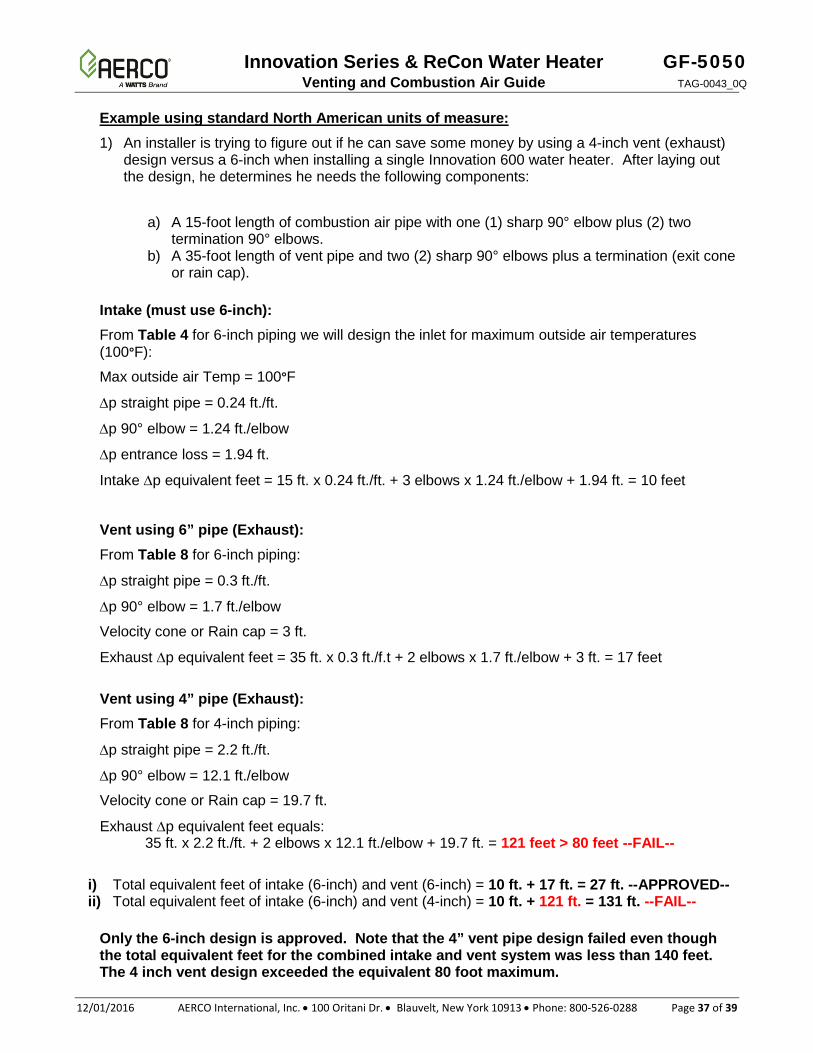
Example using standard North American units of measure: 1) An installer is trying to figure out if he can save some money by using a 4-inch vent (exhaust)
design versus a 6-inch when installing a single Innovation 600 water heater. After laying out the design, he determines he needs the following components:
a) A 15-foot length of combustion air pipe with one (1) sharp 90° elbow plus (2) two
termination 90° elbows. b) A 35-foot length of vent pipe and two (2) sharp 90° elbows plus a termination (exit cone
or rain cap).
Intake (must use 6-inch): From Table 4 for 6-inch piping we will design the inlet for maximum outside air temperatures (100°F):
Max outside air Temp = 100°F
∆p straight pipe = 0.24 ft./ft.
∆p 90° elbow = 1.24 ft./elbow
∆p entrance loss = 1.94 ft.
Intake ∆p equivalent feet = 15 ft. x 0.24 ft./ft. + 3 elbows x 1.24 ft./elbow + 1.94 ft. = 10 feet
Vent using 6” pipe (Exhaust): From Table 8 for 6-inch piping:
∆p straight pipe = 0.3 ft./ft.
∆p 90° elbow = 1.7 ft./elbow
Velocity cone or Rain cap = 3 ft.
Exhaust ∆p equivalent feet = 35 ft. x 0.3 ft./f.t + 2 elbows x 1.7 ft./elbow + 3 ft. = 17 feet
Vent using 4” pipe (Exhaust): From Table 8 for 4-inch piping:
∆p straight pipe = 2.2 ft./ft.
∆p 90° elbow = 12.1 ft./elbow
Velocity cone or Rain cap = 19.7 ft.
Exhaust ∆p equivalent feet equals: 35 ft. x 2.2 ft./ft. + 2 elbows x 12.1 ft./elbow + 19.7 ft. = 121 feet > 80 feet --FAIL--
i) Total equivalent feet of intake (6-inch) and vent (6-inch) = 10 ft. + 17 ft. = 27 ft. --APPROVED-- ii) Total equivalent feet of intake (6-inch) and vent (4-inch) = 10 ft. + 121 ft. = 131 ft. --FAIL--
Only the 6-inch design is approved. Note that the 4” vent pipe design failed even though the total equivalent feet for the combined intake and vent system was less than 140 feet. The 4 inch vent design exceeded the equivalent 80 foot maximum.
GF-5050 Innovation Series & ReCon Water Heater TAG-0043_0Q Venting and Combustion Air Guide
Page 38 of 39 AERCO International, Inc. • 100 Oritani Dr. • Blauvelt, New York 10913 • Phone: 800-526-0288 12/01/2016
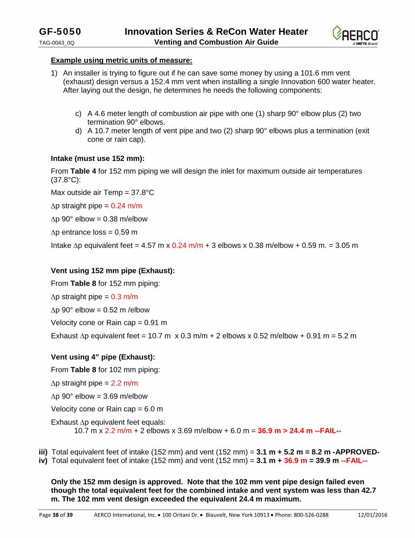
Example using metric units of measure: 1) An installer is trying to figure out if he can save some money by using a 101.6 mm vent
(exhaust) design versus a 152.4 mm vent when installing a single Innovation 600 water heater. After laying out the design, he determines he needs the following components:
c) A 4.6 meter length of combustion air pipe with one (1) sharp 90° elbow plus (2) two
termination 90° elbows. d) A 10.7 meter length of vent pipe and two (2) sharp 90° elbows plus a termination (exit
cone or rain cap).
Intake (must use 152 mm): From Table 4 for 152 mm piping we will design the inlet for maximum outside air temperatures (37.8°C):
Max outside air Temp = 37.8°C
∆p straight pipe = 0.24 m/m
∆p 90° elbow = 0.38 m/elbow
∆p entrance loss = 0.59 m
Intake ∆p equivalent feet = 4.57 m x 0.24 m/m + 3 elbows x 0.38 m/elbow + 0.59 m. = 3.05 m
Vent using 152 mm pipe (Exhaust): From Table 8 for 152 mm piping:
∆p straight pipe = 0.3 m/m
∆p 90° elbow = 0.52 m /elbow
Velocity cone or Rain cap = 0.91 m
Exhaust ∆p equivalent feet = 10.7 m x 0.3 m/m + 2 elbows x 0.52 m/elbow + 0.91 m = 5.2 m
Vent using 4” pipe (Exhaust): From Table 8 for 102 mm piping:
∆p straight pipe = 2.2 m/m
∆p 90° elbow = 3.69 m/elbow
Velocity cone or Rain cap = 6.0 m
Exhaust ∆p equivalent feet equals: 10.7 m x 2.2 m/m + 2 elbows x 3.69 m/elbow + 6.0 m = 36.9 m > 24.4 m --FAIL--
iii) Total equivalent feet of intake (152 mm) and vent (152 mm) = 3.1 m + 5.2 m = 8.2 m -APPROVED- iv) Total equivalent feet of intake (152 mm) and vent (152 mm) = 3.1 m + 36.9 m = 39.9 m --FAIL--
Only the 152 mm design is approved. Note that the 102 mm vent pipe design failed even though the total equivalent feet for the combined intake and vent system was less than 42.7 m. The 102 mm vent design exceeded the equivalent 24.4 m maximum.
Innovation Series & ReCon Water Heater GF-5050 Venting and Combustion Air Guide TAG-0043_0Q
12/01/2016 AERCO International, Inc. • 100 Oritani Dr. • Blauvelt, New York 10913 • Phone: 800-526-0288 Page 39 of 39
© AERCO International, Inc., 2016
Change Log Date Description Changed By
05/15/2015
Rev P PIRs: 934-127: Corrected part numbers in Figure 1; added vent adapter 39006-1 to section 1.5; new sections 1.6 & 1.7; added note 5 to section 2.1; removed 1st row (INN 600) with 4” diameter from Table 2; revised Required Transition Vent Sections in Figures 13 & 14. 934-143: Add exit cones (velocity cone) as preferred alternative to rain cap, sections 3.3 & 3.4. 934-186: Remove references to ReCon 500.
Chris Blair
12/01/2016 Rev Q PIR/DIRs: DIR 357: Added dual dimensioning (standard and metric), added additional venting options in Figure 7b.
Chris Blair