ventilateur en caisson tvec ii / vik micro-watt · trasformazione di un tvec ii / vik standard in...
TRANSCRIPT
GB
D
I
E
Assembly InstructionsFan in casing TVEC II / VIK micro-watt
MontageanleitungLüfter in Gehäuse TVEC II / VIK micro-watt
Istruzioni di montaggioVentilatore in cassone TVEC II / VIK micro-watt
Manual del operadorVentilador en caja TVEC II / VIK micro-watt
www.aldes.com
110
56 8
41 -
RC
S 9
56 5
06 8
28 -
Imp
rimé
en F
ranc
e/P
rinte
d in
Fra
nce
N o t i c e d e M o n t a g e
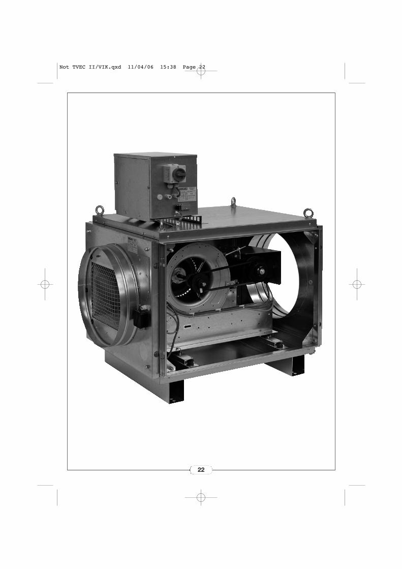
Ventilateur en caissonTVEC II / VIK micro-watt
Not TVEC II/VIK.qxd 11/04/06 15:38 Page 1
Identification IdentifizierungIdentificazione Identificación
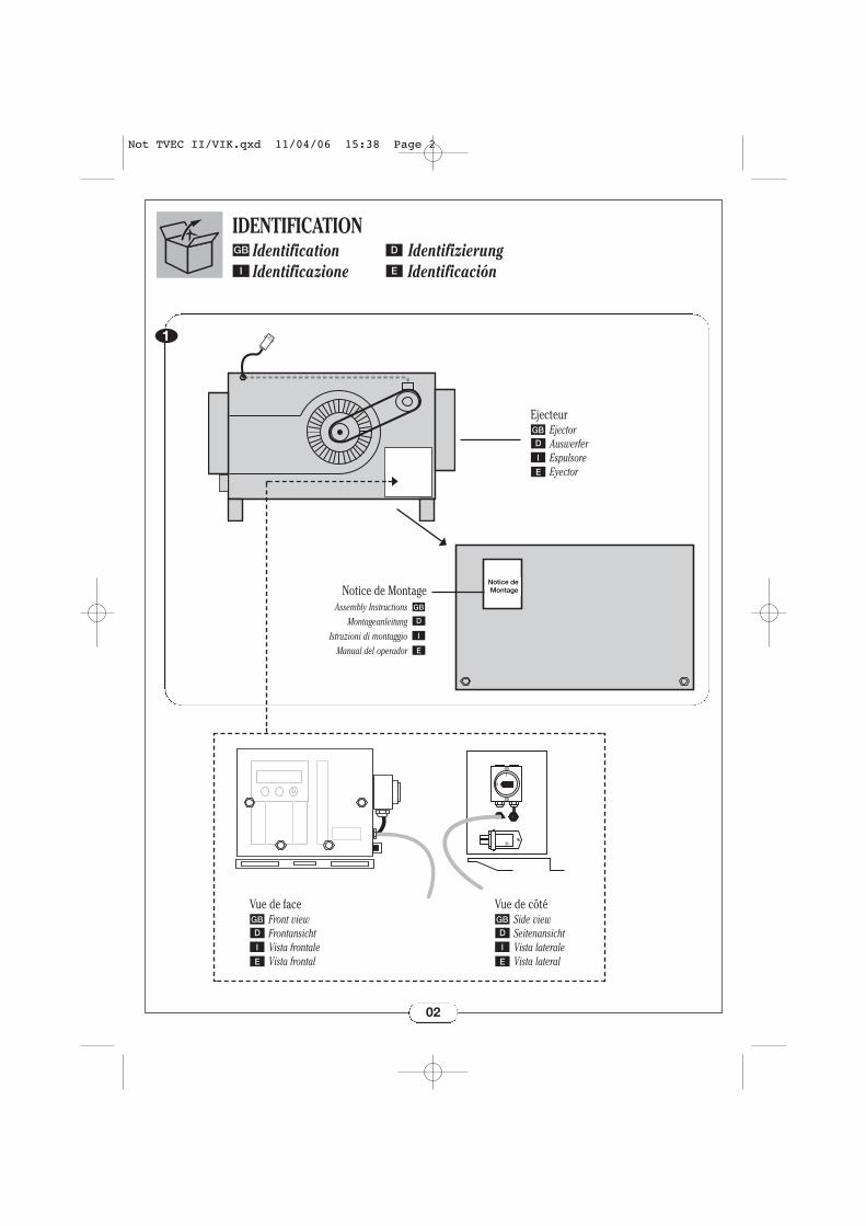
IDENTIFICATION
02
GB D
I E
GB
D
I
E
Assembly InstructionsMontageanleitung
Istruzioni di montaggioManual del operador
Vue de faceFront view FrontansichtVista frontale Vista frontal
GB
D
I
E
Vue de côtéSide view SeitenansichtVista laterale Vista lateral
GB
D
I
E
1
0
Notice de MontageNotice de Montage
EjecteurEjector AuswerferEspulsore Eyector
GB
D
I
E
1
Not TVEC II/VIK.qxd 11/04/06 15:38 Page 2
Installation InstallationInstallazione Instalación
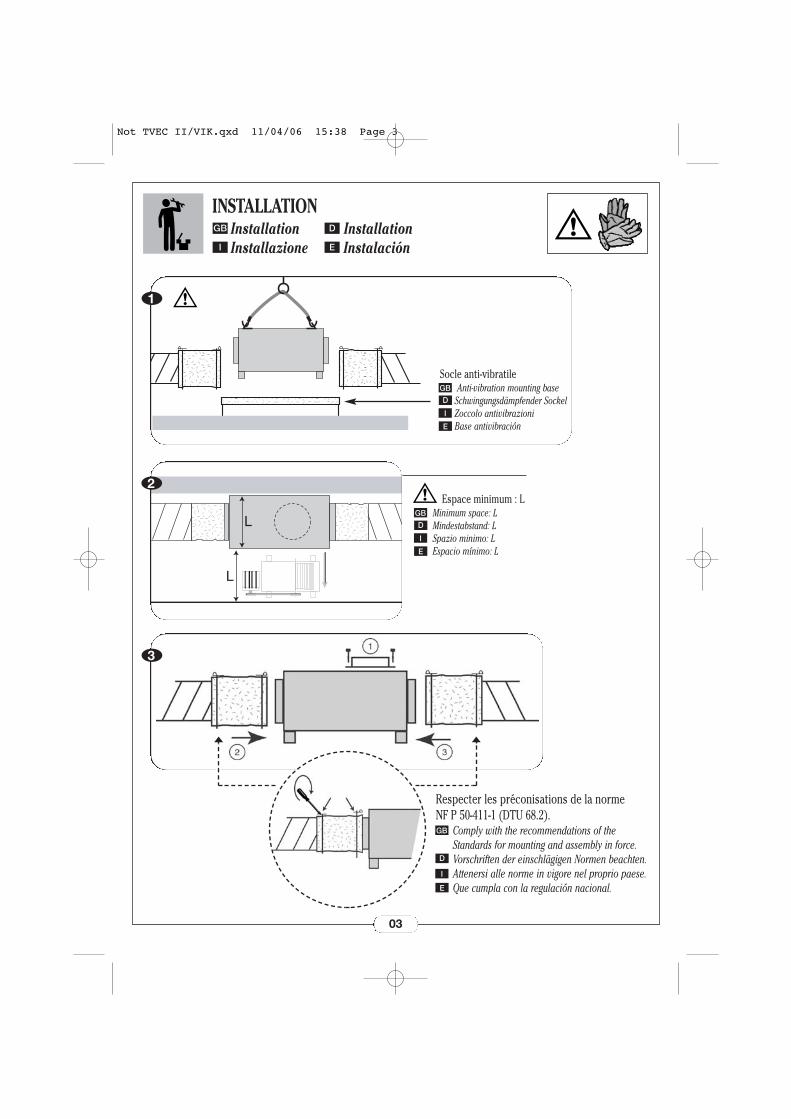
INSTALLATION
1
L
L
2
03
GB D
I E
Socle anti-vibratileAnti-vibration mounting base
Schwingungsdämpfender SockelZoccolo antivibrazioniBase antivibración
GB
D
I
E
3
Espace minimum : LMinimum space: LMindestabstand: LSpazio minimo: LEspacio mínimo: L
GB
D
I
E
Respecter les préconisations de la norme NF P 50-411-1 (DTU 68.2).
Comply with the recommendations of theStandards for mounting and assembly in force.Vorschriften der einschlägigen Normen beachten.Attenersi alle norme in vigore nel proprio paese. Que cumpla con la regulación nacional.
GB
D
I
E
Not TVEC II/VIK.qxd 11/04/06 15:38 Page 3
Warnings WarnhinweiseAvvertenze Advertencia
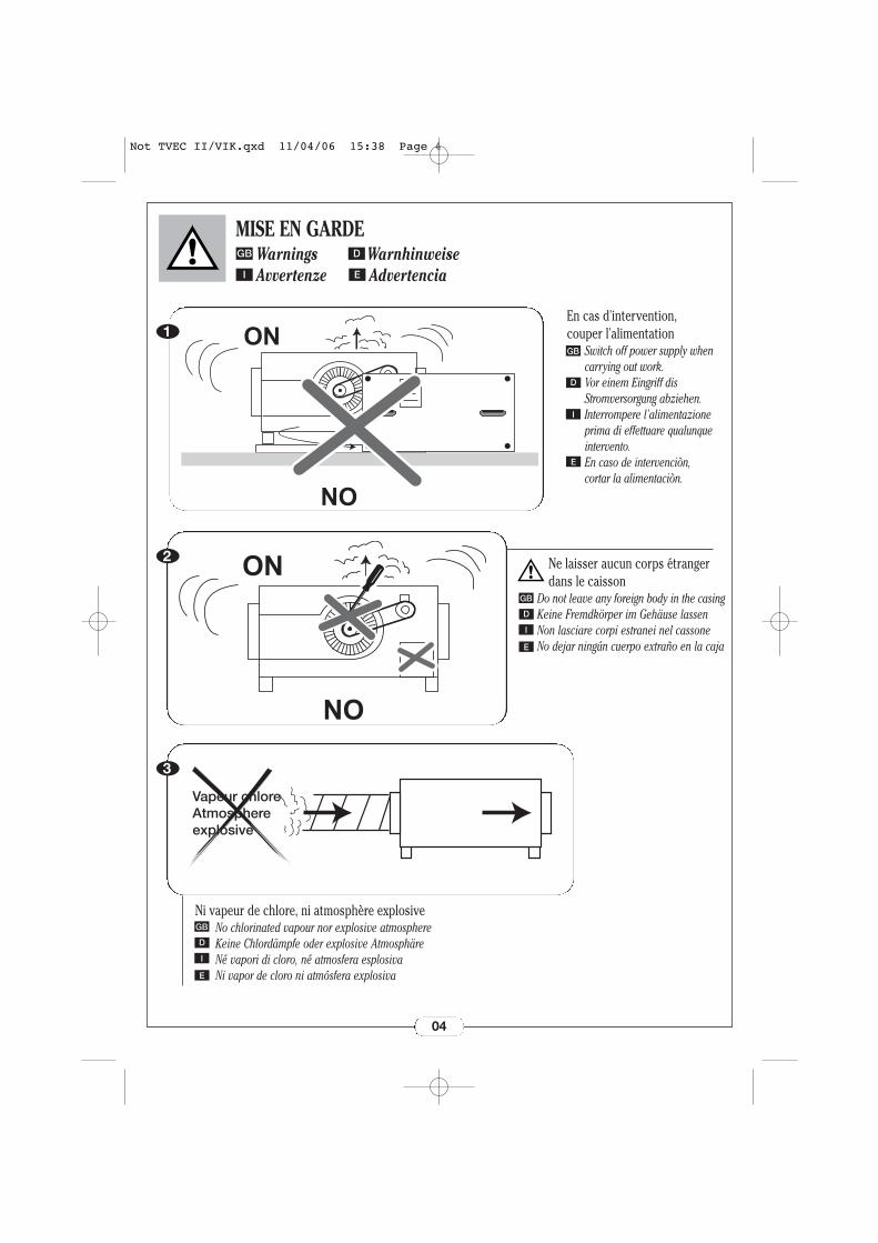
MISE EN GARDE
ON
NO
VEC
1
NO
ON2
Vapeur chloreAtmosphereexplosive
3
04
GB D
I E
Ni vapeur de chlore, ni atmosphère explosiveNo chlorinated vapour nor explosive atmosphereKeine Chlordämpfe oder explosive AtmosphäreNé vapori di cloro, né atmosfera esplosivaNi vapor de cloro ni atmósfera explosiva
GB
D
I
E
Ne laisser aucun corps étranger dans le caisson
Do not leave any foreign body in the casingKeine Fremdkörper im Gehäuse lassenNon lasciare corpi estranei nel cassoneNo dejar ningún cuerpo extraño en la caja
GB
D
I
E
En cas d'intervention, couper l'alimentation
Switch off power supply whencarrying out work.Vor einem Eingriff disStromversorgung abziehen.Interrompere l'alimentazioneprima di effettuare qualunqueintervento.En caso de intervenciòn, cortar la alimentaciòn.
GB
D
I
E
Not TVEC II/VIK.qxd 11/04/06 15:38 Page 4
05
Start-up InbetriebnahmeAvviamento Puesta en marcha
MISE EN ROUTEGB D
I E
GB
I
1
TVEC II / VIK
1
0
1
0
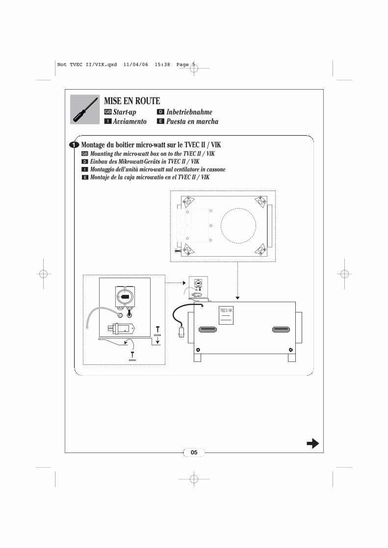
Montage du boitier micro-watt sur le TVEC II / VIKMounting the micro-watt box on to the TVEC II / VIKEinbau des Mikrowatt-Geräts in TVEC II / VIKMontaggio dell'unità micro-watt sul ventilatore in cassoneMontaje de la caja microwatio en el TVEC II / VIK
D
E
Not TVEC II/VIK.qxd 11/04/06 15:38 Page 5
06
Start-up InbetriebnahmeAvviamento Puesta en marcha
MISE EN ROUTEGB D
I E
2
X
X
CE
P1
P2
X
X
CE
P2
P1
2
1
0
3
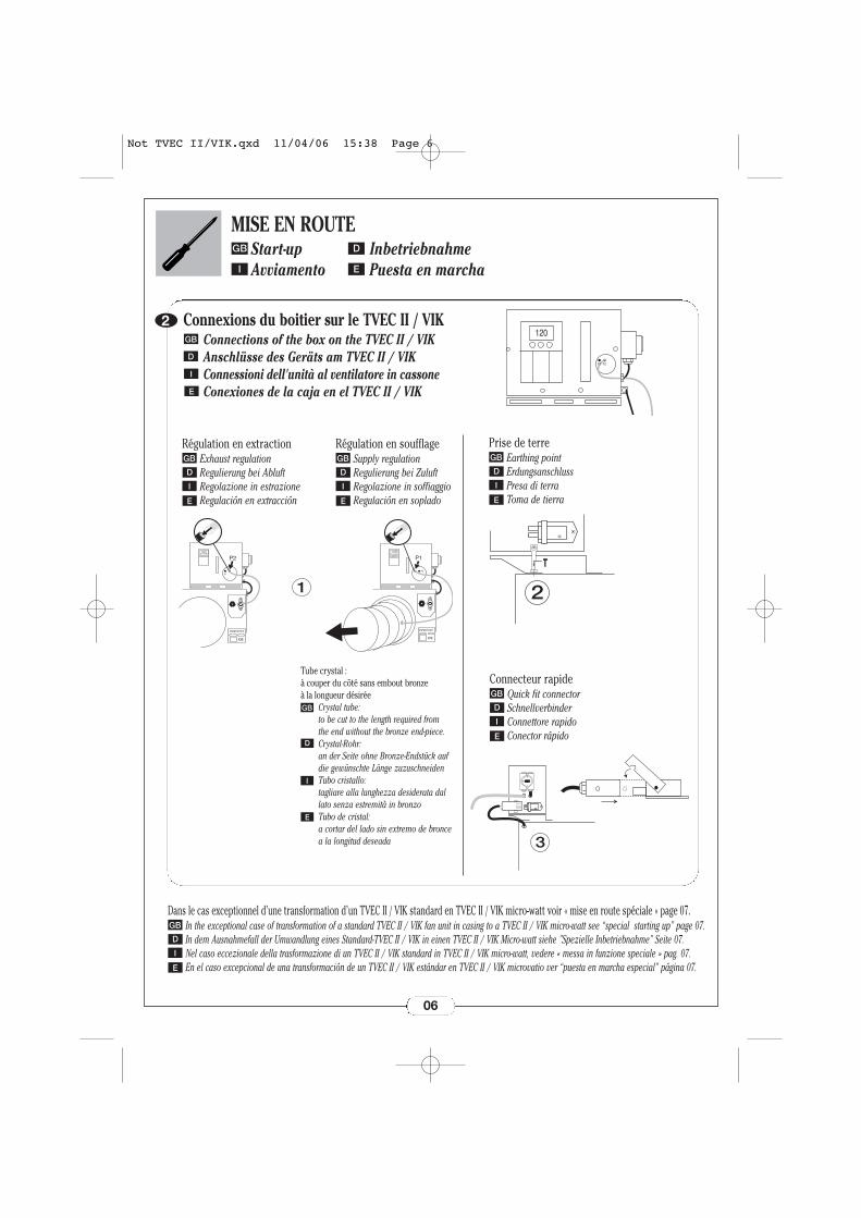
Prise de terreEarthing pointErdungsanschlussPresa di terraToma de tierra
GB
D
I
E
Connecteur rapideQuick fit connectorSchnellverbinderConnettore rapidoConector rápido
GB
D
I
E
Connexions du boitier sur le TVEC II / VIKConnections of the box on the TVEC II / VIKAnschlüsse des Geräts am TVEC II / VIKConnessioni dell'unità al ventilatore in cassoneConexiones de la caja en el TVEC II / VIK
GB
I
E
D
Dans le cas exceptionnel d’une transformation d’un TVEC II / VIK standard en TVEC II / VIK micro-watt voir « mise en route spéciale » page 07.In the exceptional case of transformation of a standard TVEC II / VIK fan unit in casing to a TVEC II / VIK micro-watt see “special starting up” page 07.In dem Ausnahmefall der Umwandlung eines Standard-TVEC II / VIK in einen TVEC II / VIK Micro-watt siehe "Spezielle Inbetriebnahme" Seite 07.Nel caso eccezionale della trasformazione di un TVEC II / VIK standard in TVEC II / VIK micro-watt, vedere « messa in funzione speciale » pag. 07.En el caso excepcional de una transformación de un TVEC II / VIK estándar en TVEC II / VIK microvatio ver “puesta en marcha especial” página 07.
GB
D
I
E
1
Régulation en extractionExhaust regulationRegulierung bei AbluftRegolazione in estrazioneRegulación en extracción
GB
D
I
E
Régulation en soufflageSupply regulationRegulierung bei ZuluftRegolazione in soffiaggioRegulación en soplado
GB
D
I
E
120
P2P1
Tube crystal : à couper du côté sans embout bronze à la longueur désirée
Crystal tube:to be cut to the length required from the end without the bronze end-piece.Crystal-Rohr:an der Seite ohne Bronze-Endstück auf die gewünschte Länge zuzuschneidenTubo cristallo:tagliare alla lunghezza desiderata dal lato senza estremità in bronzo Tubo de cristal:a cortar del lado sin extremo de bronce a la longitud deseada
GB
D
I
E
Not TVEC II/VIK.qxd 11/04/06 15:38 Page 6
MISE EN ROUTE SPÉCIALEGB
I
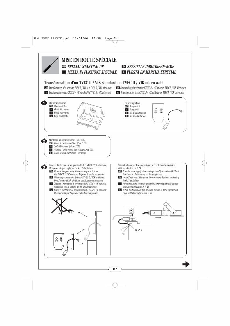
Transformation d’un TVEC II / VIK standard en TVEC II / VIK micro-wattTransformation of a standard TVEC II / VIK to a TVEC II / VIK micro-watt Umwandlung eines Standard-TVEC II / VIK in einen TVEC II / VIK Micro-wattTrasformazione di un TVEC II / VIK standard in TVEC II / VIK micro-watt Transformación de un TVEC II / VIK estándar en TVEC II / VIK microvatio
GB D
I E
1
2
07
SPECIAL STARTING UP SPEZIELLE INBETRIEBNAHMEMESSA IN FUNZIONE SPECIALE PUESTA EN MARCHA ESPECIAL
D
E
Montez le boîtier micro-watt (Voir P.05)Mount the micro-watt box (See P. 05)Gerät Micro-watt (siehe S.05)Montare l'unità micro-watt (vedere pag. 05).Monte la caja microvatio (Ver P.05)
GB
D
I
E
Boîtier micro-watt Micro-watt box Gerät Micro-watt Unità micro-watt Caja microvatio
GB
D
I
E
3Enlevez l’interrupteur de proximité du TVEC II / VIK standardRemplacez-le par la plaque du kit d’adaptation
Remove the proximity disconnecting switch from the TVEC II / VIK standard. Replace it by the adapter kitNäherungsschalter des Standard-TVEC II / VIK entfernen.Den Schalter durch die Platte des Adapterkits ersetzen.Togliere l'interruttore di prossimità del TVEC II / VIK standard.Sostituirlo con la piastra del kit di adattamento.Retire el interruptor de proximidad del TVEC II / VIK estándarReemplácelo por la plaque del kit de adaptación
GB
D
I
E
Si insufflation avec train de caisson percez le haut du caissoncôté insufflation en Ø 23.
If used for air supply via a casing assembly – make a Ø 23 cutinto the top of the casing on the supply side wenn Zuluft mit Lüfterkasten Oberseite des Kastens zuluftseitigin Ø 23 aufbohrenPer insufflazione con treno di cassoni, forare la parte alta del cas-sone lato insufflazione in Ø 23Si hay insuflación con tren de cajón, perfore la parte superior delcajón del lado insuflación en Ø 23
GB
D
I
E
Kit d’adaptationAdapter kit AdapterkitKit di adattamentoKit de adaptación
GB
D
I
E
1
0
Not TVEC II/VIK.qxd 11/04/06 15:38 Page 7
MISE EN ROUTE SPÉCIALEGB
I
4
08
SPECIAL STARTING UP SPEZIELLE INBETRIEBNAHMEMESSA IN FUNZIONE SPECIALE PUESTA EN MARCHA ESPECIAL
D
E
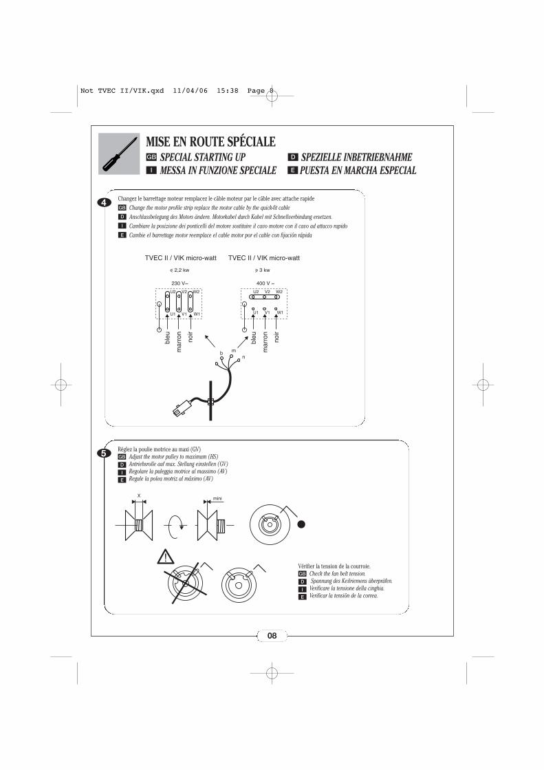
Changez le barrettage moteur remplacez le câble moteur par le câble avec attache rapideChange the motor profile strip replace the motor cable by the quick-fit cableAnschlussbelegung des Motors ändern. Motorkabel durch Kabel mit Schnellverbindung ersetzen.Cambiare la posizione dei ponticelli del motore sostituire il cavo motore con il cavo ad attacco rapidoCambie el barrettage motor reemplace el cable motor por el cable con fijación rápida
GB
D
I
E
5 Réglez la poulie motrice au maxi (GV)Adjust the motor pulley to maximum (HS)Antriebsrolle auf max. Stellung einstellen (GV)Regolare la puleggia motrice al massimo (AV)Regule la polea motriz al máximo (AV)
GB
D
I
E
Vérifier la tension de la courroie.Check the fan belt tension.Spannung des Keilriemens überprüfen.
Verificare la tensione della cinghia.Verificar la tensión de la correa.
GB
D
I
E
bleu
mar
ron
noir
bleu
mar
ron
noir
TVEC II / VIK micro-watt TVEC II / VIK micro-watt
230 V~ 400 V ~
b mn
U1
U2 V2 W2
V1 W1 U1
U2 V2 W2
V1 W1
< 2,2 kw > 3 kw
Xmini
Not TVEC II/VIK.qxd 11/04/06 15:38 Page 8
MISE EN ROUTE : Raccordement éléctriqueGB
I E
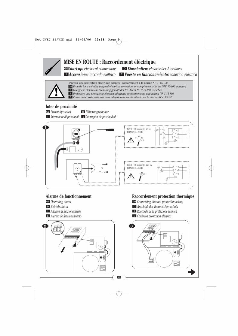
Inter de proximitéProximity switch NäherungsschalterInterruttore di prossimità Interruptor de proximidad
GB D
I E
Alarme de fonctionnementOperating alarmBetriebsalarmAllarme di funzionamentoAlarma de funcionamiento
GB
D
I
E
11
0
09
Start-up: electrical connections Einschalten: elektrischer AnschlussAccensione: raccordo elettrico Puesta en funcionamiento: conexión eléctrica
D
TVEC II / VIK micro-watt : ≥ 3 kw400 VAC, 3 ~, 50 Hz
X
X
CE
K12
K14 K11
2
Raccordement protection thermiqueConnecting thermal protection wiringAnschlub des thermischen schutzRaccordo della protezione termicaConexion proteccion electrica
GB
D
I
E
X
X
CE
2423
L1L2
L3
L1
L2
L3
1 2
43
65
L N
TVEC II / VIK micro-watt : ≥ 2,2 kw230 VAC, 2 ~, 50 Hz
L
N
1 2
43
L2
L1
65
Prévoir une protection électrique adaptée, conformment à la norme NF C 15-100Provide for a suitably adapted electrical protection, in compliance with the NFC 15-100 standardGeeignete elektrische Sicherung gemäß der frz. Norm NF C 15-100 vorsehen.Prevedere una protezione elettrica adeguata, conformemente alla norma NF C 15-100.Prever una protección eléctrica adaptada de conformidad con la norma NF C 15-100.
GBDI
E
Not TVEC II/VIK.qxd 11/04/06 15:38 Page 9
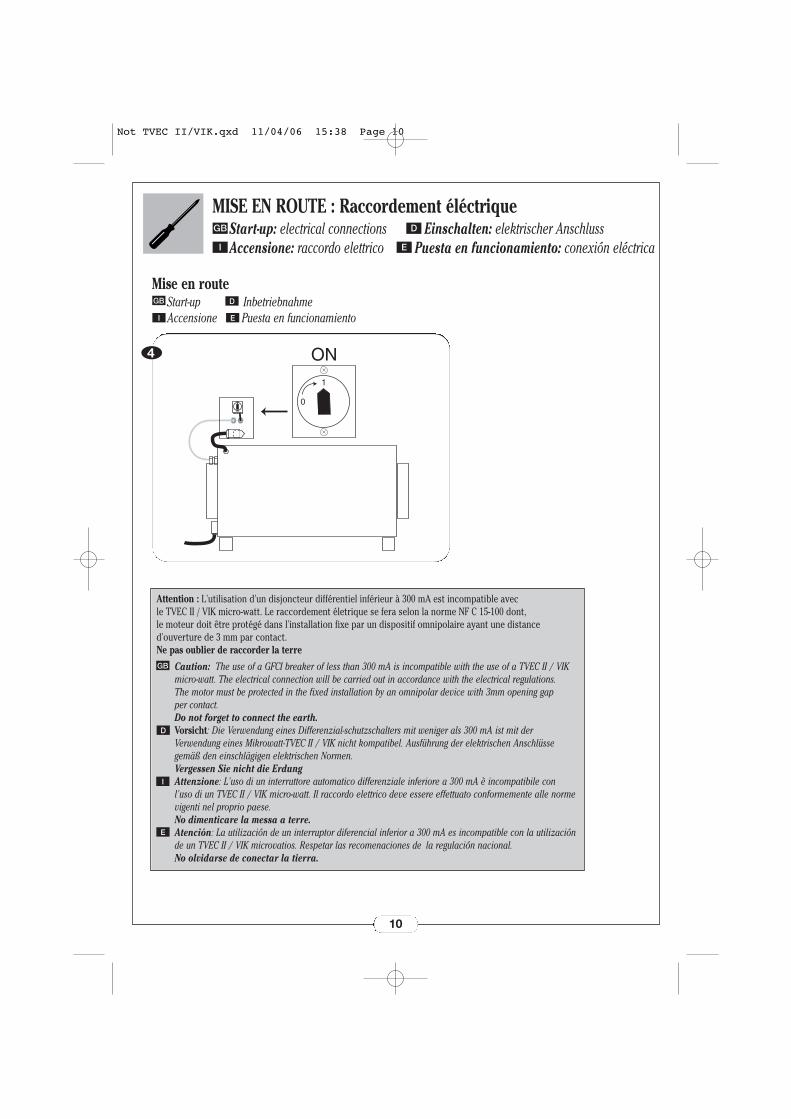
MISE EN ROUTE : Raccordement éléctriqueGB
I E
4
1
0
ON
Mise en routeStart-up InbetriebnahmeAccensione Puesta en funcionamiento
GB D
I E
10
Attention : L'utilisation d'un disjoncteur différentiel inférieur à 300 mA est incompatible avec le TVEC II / VIK micro-watt. Le raccordement életrique se fera selon la norme NF C 15-100 dont, le moteur doit être protégé dans l'installation fixe par un dispositif omnipolaire ayant une distanced'ouverture de 3 mm par contact. Ne pas oublier de raccorder la terre
Caution: The use of a GFCI breaker of less than 300 mA is incompatible with the use of a TVEC II / VIKmicro-watt. The electrical connection will be carried out in accordance with the electrical regulations. The motor must be protected in the fixed installation by an omnipolar device with 3mm opening gap per contact. Do not forget to connect the earth.Vorsicht: Die Verwendung eines Differenzial-schutzschalters mit weniger als 300 mA ist mit derVerwendung eines Mikrowatt-TVEC II / VIK nicht kompatibel. Ausführung der elektrischen Anschlüssegemäß den einschlägigen elektrischen Normen.Vergessen Sie nicht die ErdungAttenzione: L'uso di un interruttore automatico differenziale inferiore a 300 mA è incompatibile con l'uso di un TVEC II / VIK micro-watt. Il raccordo elettrico deve essere effettuato conformemente alle normevigenti nel proprio paese. No dimenticare la messa a terre.Atención: La utilización de un interruptor diferencial inferior a 300 mA es incompatible con la utilizaciónde un TVEC II / VIK microvatios. Respetar las recomenaciones de la regulación nacional. No olvidarse de conectar la tierra.
GB
D
I
E
Start-up: electrical connections Einschalten: elektrischer AnschlussAccensione: raccordo elettrico Puesta en funcionamiento: conexión eléctrica
D
Not TVEC II/VIK.qxd 11/04/06 15:38 Page 10
11
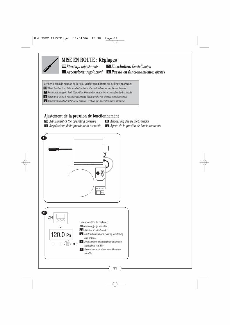
MISE EN ROUTE : Réglages
X
X
CE
Ajustement de la pression de fonctionnementAdjustment of the operating pressure Anpassung des BetriebsdrucksRegolazione della pressione di esercizio Ajuste de la presión de funcionamiento
GB D
I E
1
2
120,0 Pa
-
+
ONPotentiomètre de réglage : Attention réglage sensible
Adjustment potentiometerEinstell-Potentiometer: Achtung, Einstellungsehr sensibelPotenziometro di regolazione: attenzione,regolazione sensibilePotenciómetro de ajuste: atención ajustesensible
GB
D
I
E
GB
I E
Start-up: adjustments Einschalten: EinstellungenAccensione: regolazioni Puesta en funcionamiento: ajustes
D
Vérifier le sens de rotation de la roue. Vérifier qu’il n’existe pas de bruits anormaux.Check the direction of the impeller's rotation. Check that there are no abnormal noises.
Rotationsrichtung des Rads überprüfen. Sicherstellen, dass es keine anomalen Geräusche gibt.
Verificare il senso di rotazione della ruota. Verificare che non ci siano rumori anormali.
Verificar el sentido de rotación de la rueda. Verificar que no existen ruidos anormales.
GB
D
I
E
Not TVEC II/VIK.qxd 11/04/06 15:38 Page 11
12
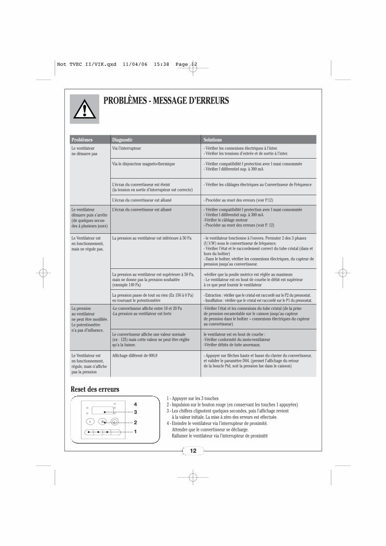
PROBLÈMES - MESSAGE D’ERREURS
Le ventilateur ne démarre pas
Via l’interrupteur
Via le disjoncteur magneto-thermique
L’écran du convertisseur est éteint (la tension en sortie d’interrupteur est correcte)
L’écran du convertisseur est allumé
- Vérifier les connexions électriques à l’inter.- Vérifier les tensions d’entrée et de sortie à l’inter.
- Vérifier compatibilité I protection avec I maxi consommée - Vérifier I différentiel sup. à 300 mA
- Vérifier les câblages électriques au Convertisseur de Fréquence
- Procéder au reset des erreurs (voir P.12)
Problèmes Diagnostic Solutions
Le ventilateur démarre puis s’arrête(de quelques secon-des à plusieurs jours)
L’écran du convertisseur est allumé - Vérifier compatibilité I protection avec I maxi consommée - Vérifier I différentiel sup. à 300 mA-Vérifier le câblage moteur- Procéder au reset des erreurs (voir P. 12)
Le Ventilateur est en fonctionnement,mais ne régule pas.
La pression au ventilateur est inférieure à 50 Pa
La pression au ventilateur est supérieure à 50 Pa,mais ne donne pas la pression souhaitée (exemple 140 Pa)
La pression passe de tout ou rien (Ex 150 à 0 Pa) en tournant le potentiomètre
- le ventilateur fonctionne à l’envers. Permuter 2 des 3 phases(U,V,W) sous le convertisseur de fréquence.- Vérifier l’état et le raccordement correct du tube cristal (dans ethors du boîtier)- Dans le boîtier, vérifier les connexions électriques, du capteur depression jusqu’au convertisseur.
-vérifier que la poulie motrice est réglée au maximum- Le ventilateur est en bout de courbe le débit est supérieur à ce que peut fournir le ventilateur
- Extraction : vérifier que le cristal est raccordé sur le P2 du pressostat.- Insufflation : vérifier que le cristal est raccordé sur le P1 du pressostat.
La pression au ventilateur ne peut être modifiée.Le potentiomètre n’a pas d’influence.
-Le convertisseur affiche entre 10 et 20 Pa-La pression au ventilateur est forte
Le convertisseur affiche une valeur normale (ex : 125) mais cette valeur ne peut être réglée qu’a la baisse.
-Vérifier l’état et les connexions du tube cristal (de la prise de pression escamotable sur le caisson jusqu’au capteur de pression dans le boîtier + connexions électriques du capteurau convertisseur)
le ventilateur est en bout de courbe :-Vérifier conformité du moto-ventilateur -Vérifier débits de fuite anormaux.
Le Ventilateur est en fonctionnement,régule, mais n’affichepas la pression
Affichage différent de 000,0 - Appuyer sur flèches haute et basse du clavier du convertisseur,et valider le paramètre D04. (permet l’affichage du retour de la boucle Pid, soit la pression lue dans le caisson)
Reset des erreurs1 - Appuyer sur les 3 touches2 - Impulsion sur le bouton rouge (en conservant les touches 1 appuyées)3 - Les chiffres clignotent quelques secondes, puis l’affichage revient
à la valeur initiale. La mise à zéro des erreurs est effectuée.4 - Eteindre le ventilateur via l’interrupteur de proximité.
Attendre que le convertisseur se décharge. Rallumer le ventilateur via l’interrupteur de proximité
4
3
2
1
Not TVEC II/VIK.qxd 11/04/06 15:38 Page 12
PROBLÈMES - MESSAGE D’ERREURS
13
E01
E02
E03
E04
E05
E09
E14
E15
E08E11E22
E21
Sur-intensité à vitesse constante (ventilateur en vitesse de croisière)
Sur-intensité pendant la décélération (ventilateur en train de s’arrêter)
Sur-intensité pendant l’accélération (ventilateur en train de démarrer)
Sur-intensité à l’arrêt
Surcharge du moteur
Sous-tension du réseau
Courant de fuite à la terre
Surtension de la tension d’alimentation
Erreur de lecture EEPROM
Protection thermique de l’appareil
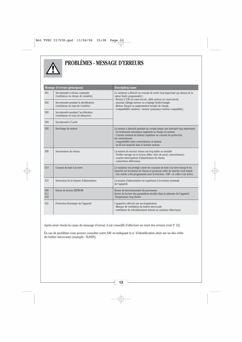
Le variateur a détecté un courant de sortie trop important (au dessus de lavaleur limite programmée) :- Bornes U,V,W en court-circuit, câble moteur en court-circuit,- mauvais câblage moteur ou couplage étoile/triangle,- Moteur bloqué ou augmentation brutale de charge,- Compatibilité variateur / moteur (puissance moteur compatible).
Le moteur a absorbé pendant un certain temps une intensité trop importante.- Un frottement mécanique augmente la charge du moteur,- Courant nominal du moteur supérieur au courant de protection du convertisseur,- compatibilité entre convertisseur et moteur.- un fil non branché dans le bornier moteur.
La tension du secteur réseau est trop faible ou instable- Vérifier serrage vis et écrous (filtre, inter de proxi, convertisseur)- courtes interruptions d’alimentation du réseau- contacteurs défectueux
Le variateur est protégé contre les courants de fuite à la terre lorsqu’il estbranché sur la tension de réseau et qu’aucun ordre de marche n’est donné.- Une entrée a été programmée avec la fonction « USP » et celle-ci est active.
La tension d’alimentation est supérieure à la tension nominale de l’appareil.
Erreur de fonctionnement du processeurErreur de lecture des paramètres stockés dans la mémoire de l’appareil-Température trop élevée
L’appareil a détecté une sur-température- Manque de ventilation du boîtier micro-watt- ventilateur de refroidissement interne au variateur défectueux
Message d’erreurs (principaux) Description/cause
Après avoir résolu la cause du message d’erreur, il est conseillé d’effectuer un reset des erreurs (voir P. 12).
En cas de problème vous pouvez consulter notre SAV en indiquant le n° d’identification situé sur un des côtés du boîtier micro-watt (exemple : 5L8459).
Not TVEC II/VIK.qxd 11/04/06 15:38 Page 13
4
3
2
1
PROBLEMS - ERROR MESSAGESGB
14
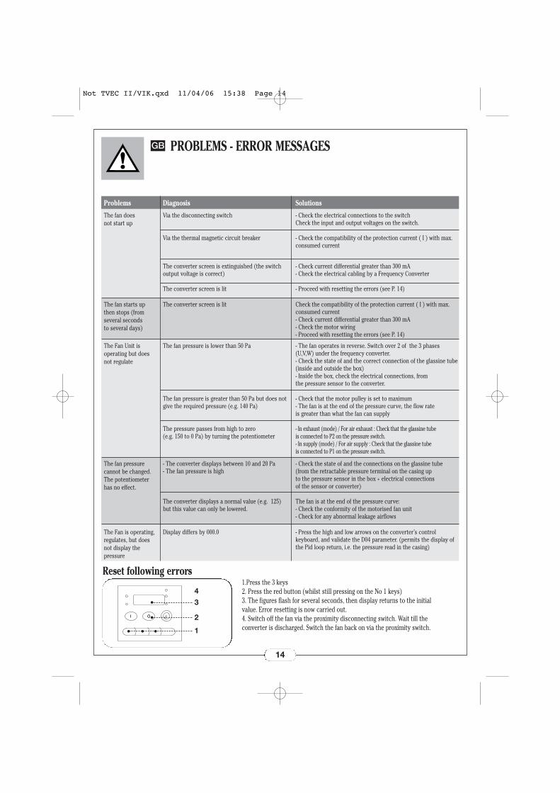
The fan does not start up
Via the disconnecting switch
Via the thermal magnetic circuit breaker
The converter screen is extinguished (the switchoutput voltage is correct)
The converter screen is lit
- Check the electrical connections to the switchCheck the input and output voltages on the switch.
- Check the compatibility of the protection current ( I ) with max.consumed current
- Check current differential greater than 300 mA- Check the electrical cabling by a Frequency Converter
- Proceed with resetting the errors (see P. 14)
Problems Diagnosis Solutions
The fan starts up then stops (fromseveral seconds to several days)
The converter screen is lit Check the compatibility of the protection current ( I ) with max.consumed current- Check current differential greater than 300 mA- Check the motor wiring- Proceed with resetting the errors (see P. 14)
The Fan Unit is operating but doesnot regulate
The fan pressure is lower than 50 Pa
The fan pressure is greater than 50 Pa but does notgive the required pressure (e.g. 140 Pa)
The pressure passes from high to zero (e.g. 150 to 0 Pa) by turning the potentiometer
- The fan operates in reverse. Switch over 2 of the 3 phases(U,V,W) under the frequency converter.- Check the state of and the correct connection of the glassine tube(inside and outside the box) - Inside the box, check the electrical connections, from the pressure sensor to the converter.
- Check that the motor pulley is set to maximum- The fan is at the end of the pressure curve, the flow rate is greater than what the fan can supply
- In exhaust (mode) / For air exhaust : Check that the glassine tube is connected to P2 on the pressure switch.- In supply (mode) / For air supply : Check that the glassine tube is connected to P1 on the pressure switch.
The fan pressure cannot be changed.The potentiometerhas no effect.
- The converter displays between 10 and 20 Pa- The fan pressure is high
The converter displays a normal value (e.g. 125)but this value can only be lowered.
- Check the state of and the connections on the glassine tube(from the retractable pressure terminal on the casing up to the pressure sensor in the box + electrical connections of the sensor or converter)
The fan is at the end of the pressure curve:- Check the conformity of the motorised fan unit- Check for any abnormal leakage airflows
The Fan is operating,regulates, but doesnot display the pressure
Display differs by 000.0 - Press the high and low arrows on the converter’s control keyboard, and validate the D04 parameter. (permits the display ofthe Pid loop return, i.e. the pressure read in the casing)
Reset following errors1.Press the 3 keys2. Press the red button (whilst still pressing on the No 1 keys)3. The figures flash for several seconds, then display returns to the initialvalue. Error resetting is now carried out.4. Switch off the fan via the proximity disconnecting switch. Wait till theconverter is discharged. Switch the fan back on via the proximity switch.
Not TVEC II/VIK.qxd 11/04/06 15:38 Page 14
E01
E02
E03
E04
E05
E09
E14
E15
E08E11E22
E21
Overcurrent at constant speed (fan at cruising speed)
Overcurrent during deceleration (fan about to stop)
Overcurrent during acceleration (fan is starting up)
Overcurrent when stopped
Motor overload
Network undervoltage
Earth leakage current
Overvoltage on the power supply voltage
EEPROM reading error
Thermal protection of the device
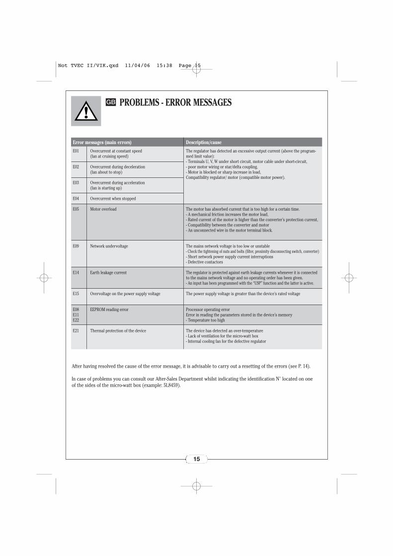
The regulator has detected an excessive output current (above the program-med limit value):- Terminals U, V, W under short circuit, motor cable under short-circuit,- poor motor wiring or star/delta coupling,- Motor is blocked or sharp increase in load,Compatibility regulator/ motor (compatible motor power).
The motor has absorbed current that is too high for a certain time.- A mechanical friction increases the motor load,- Rated current of the motor is higher than the converter’s protection current,- Compatibility between the converter and motor- An unconnected wire in the motor terminal block.
The mains network voltage is too low or unstable- Check the tightening of nuts and bolts (filter, proximity disconnecting switch, converter)- Short network power supply current interruptions- Defective contactors
The regulator is protected against earth leakage currents whenever it is connectedto the mains network voltage and no operating order has been given.- An input has been programmed with the “USP” function and the latter is active.
The power supply voltage is greater than the device’s rated voltage
Processor operating errorError in reading the parameters stored in the device’s memory- Temperature too high
The device has detected an over-temperature- Lack of ventilation for the micro-watt box- Internal cooling fan for the defective regulator
Error messages (main errors) Description/cause
After having resolved the cause of the error message, it is advisable to carry out a resetting of the errors (see P. 14).
In case of problems you can consult our After-Sales Department whilst indicating the identification N° located on one of the sides of the micro-watt box (example: 5L8459).
PROBLEMS - ERROR MESSAGES
15
GB
Not TVEC II/VIK.qxd 11/04/06 15:38 Page 15
4
3
2
1
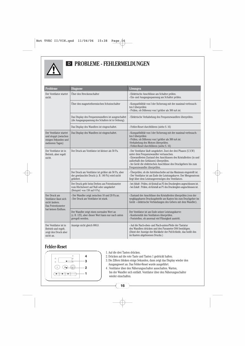
Der Ventilator startetnicht.
Über den Streckenschalter
Über den magnetothermischen Schutzschalter
Das Display des Frequenzwandlers ist ausgeschaltet(die Ausgangsspannung des Schalters ist in Ordnung).
Das Display des Wandlers ist eingeschaltet.
- Elektrische Anschlüsse am Schalter prüfen.- Ein- und Ausgangsspannung am Schalter prüfen.
- Kompatibilität von I der Sicherung mit der maximal verbrauch-ten I überprüfen - Prüfen, ob Differenz von I größer als 300 mA ist.
- Elektrische Verkabelung des Frequenzwandlers überprüfen.
- Fehler-Reset durchführen (siehe S. 16)
Probleme Diagnose Lösungen
Der Ventilator startetund stoppt (zwischeneinigen Sekunden undmehreren Tagen)
Das Display des Wandlers ist eingeschaltet. - Kompatibilität von I der Sicherung mit der maximal verbrauch-ten I überprüfen- Prüfen, ob Differenz von I größer als 300 mA ist.-Verkabelung des Motors überprüfen.- Fehler-Reset durchführen (siehe S. 16)
Der Ventilator ist inBetrieb, aber regeltnicht.
Der Druck am Ventilator ist kleiner als 50 Pa.
Der Druck am Ventilator ist größer als 50 Pa, aberder gewünschte Druck (z. B. 140 Pa) wird nicht geliefert.
Der Druck geht beim Drehen am Potentiometer vom Höchstwert auf Null oder umgekehrt (Beispiel: von 150 auf 0 Pa).
- Der Ventilator läuft umgekehrt. Zwei der drei Phasen (U,V,W)unter dem Frequenzwandler vertauschen.- Einwandfreien Zustand des Anschlusses des Kristallrohrs (in undaußerhalb des Gehäuses) überprüfen.- Im Gerät die elektrischen Anschlüsse des Druckgebers bis zumFrequenzwandler überprüfen.
- Überprüfen, ob die Antriebsscheibe auf das Maximum eingestellt ist.- Der Ventilator ist am Ende der Leistungskurve. Der Mengenstromliegt über dem Leistungsvermögen des Ventilators.
- bei Abluft : Prüfen, ob Kristall an P2 des Druckreglers angeschlossen ist.- bei Zuluft : Prüfen, ob Kristall an P1 des Druckreglers angeschlossen ist.
Der Druck amVentilator lässt sichnicht ändern. Das Potentiometerhat keinen Einfluss.
- Der Wandler zeigt zwischen 10 und 20 Pa an.- Der Druck am Ventilator ist stark.
Der Wandler zeigt einen normalen Wert an (z. B. 125), aber dieser Wert kann nur nach untengeregelt werden.
- Zustand der Anschlüsse des Kristallrohrs überprüfen (von derwegklappbaren Druckzapfstelle am Kasten bis zum Druckgeber imGerät + elektrische Verbindungen des Gebers mit dem Wandler).
Der Ventilator ist am Ende seiner Leistungskurve:- Konformität des Ventilators überprüfen.- Feststellen, ob anormal viel Flüssigkeit austritt.
Der Ventilator ist inBetrieb und regelt,zeigt den Druck abernicht an.
Anzeige nicht gleich 000,0. - Auf die Nach-oben- und Nach-unten-Pfeile der Tastatur des Wandlers drücken und den Parameter D04 bestätigen. (Dient der Anzeige der Rückkehr der Pid-Schleife, das heißt desim Kasten abgelesenen Drucks.)
Fehler-Reset1. Auf die drei Tasten drücken.2. Drücken auf die rote Taste und Tasten 1 gedrückt halten.3. Die Ziffern blinken einige Sekunden, dann zeigt das Display wieder den
Ausgangswert an. Das Fehler-Reset wurde ausgeführt.4 . Ventilator über den Näherungsschalter ausschalten. Warten,
bis der Wandler sich entlädt. Ventilator über den Näherungsschalter wieder einschalten.
PROBLEME - FEHLERMELDUNGEN
16
D
Not TVEC II/VIK.qxd 11/04/06 15:38 Page 16
E01
E02
E03
E04
E05
E09
E14
E15
E08E11E22
E21
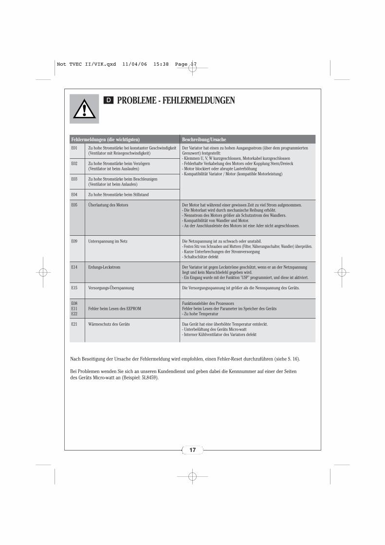
Zu hohe Stromstärke bei konstanter Geschwindigkeit(Ventilator mit Reisegeschwindigkeit)
Zu hohe Stromstärke beim Verzögern (Ventilator ist beim Auslaufen)
Zu hohe Stromstärke beim Beschleunigen (Ventilator ist beim Anlaufen)
Zu hohe Stromstärke beim Stillstand
Überlastung des Motors
Unterspannung im Netz
Erdungs-Leckstrom
Versorgungs-Überspannung
Fehler beim Lesen des EEPROM
Wärmeschutz des Geräts
Der Variator hat einen zu hohen Ausgangsstrom (über dem programmiertenGrenzwert) festgestellt:- Klemmen U, V, W kurzgeschlossen, Motorkabel kurzgeschlossen- Fehlerhafte Verkabelung des Motors oder Kopplung Stern/Dreieck- Motor blockiert oder abrupte Lasterhöhung- Kompatibilität Variator / Motor (kompatible Motorleistung)
Der Motor hat während einer gewissen Zeit zu viel Strom aufgenommen.- Die Motorlast wird durch mechanische Reibung erhöht.- Nennstrom des Motors größer als Schutzstrom des Wandlers.- Kompatibilität von Wandler und Motor.- An der Anschlussleiste des Motors ist eine Ader nicht angeschlossen.
Die Netzspannung ist zu schwach oder unstabil.- Festen Sitz von Schrauben und Muttern (Filter, Näherungsschalter, Wandler) überprüfen.- Kurze Unterbrechungen der Stromversorgung- Schaltschütze defekt
Der Variator ist gegen Leckströme geschützt, wenn er an der Netzspannungliegt und kein Marschbefehl gegeben wird.- Ein Eingang wurde mit der Funktion "USP" programmiert, und diese ist aktiviert.
Die Versorgungsspannung ist größer als die Nennspannung des Geräts.
Funktionsfehler des ProzessorsFehler beim Lesen der Parameter im Speicher des Geräts- Zu hohe Temperatur
Das Gerät hat eine überhöhte Temperatur entdeckt.- Unterbelüftung des Geräts Micro-watt- Interner Kühlventilator des Variators defekt
Fehlermeldungen (die wichtigsten) Beschreibung/Ursache
Nach Beseitigung der Ursache der Fehlermeldung wird empfohlen, einen Fehler-Reset durchzuführen (siehe S. 16).
Bei Problemen wenden Sie sich an unseren Kundendienst und geben dabei die Kennnummer auf einer der Seiten des Geräts Micro-watt an (Beispiel: 5L8459).
PROBLEME - FEHLERMELDUNGEN
17
D
Not TVEC II/VIK.qxd 11/04/06 15:38 Page 17
4
3
2
1
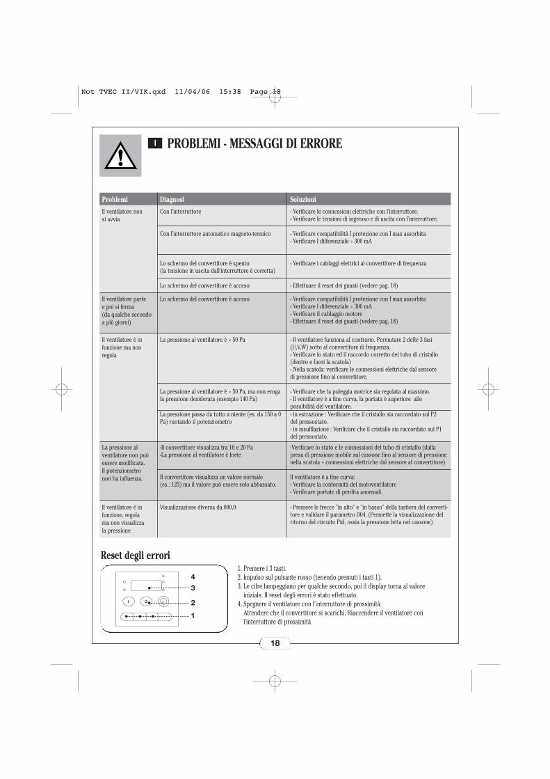
Il ventilatore non si avvia
Con l'interruttore
Con l'interruttore automatico magneto-termico
Lo schermo del convertitore è spento (la tensione in uscita dall'interruttore è corretta)
Lo schermo del convertitore è acceso
- Verificare le connessioni elettriche con l'interruttore.- Verificare le tensioni di ingresso e di uscita con l'interruttore.
- Verificare compatibilità I protezione con I max assorbita - Verificare I differenziale > 300 mA
- Verificare i cablaggi elettrici al convertitore di frequenza
- Effettuare il reset dei guasti (vedere pag. 18)
Problemi Diagnosi Soluzioni
Il ventilatore parte e poi si ferma (da qualche secondoa più giorni)
Lo schermo del convertitore è acceso - Verificare compatibilità I protezione con I max assorbita - Verificare I differenziale > 300 mA- Verificare il cablaggio motore- Effettuare il reset dei guasti (vedere pag. 18)
Il ventilatore è in funzione ma non regola
La pressione al ventilatore è < 50 Pa
La pressione al ventilatore è > 50 Pa, ma non erogala pressione desiderata (esempio 140 Pa)
La pressione passa da tutto a niente (es. da 150 a 0Pa) ruotando il potenziometro
- Il ventilatore funziona al contrario. Permutare 2 delle 3 fasi(U,V,W) sotto al convertitore di frequenza.- Verificare lo stato ed il raccordo corretto del tubo di cristallo(dentro e fuori la scatola)- Nella scatola: verificare le connessioni elettriche dal sensore di pressione fino al convertitore.
- Verificare che la puleggia motrice sia regolata al massimo.- Il ventilatore è a fine curva, la portata è superiore alle possibilità del ventilatore.- in estrazione : Verificare che il cristallo sia raccordato sul P2 del pressostato.- in insufflazione : Verificare che il cristallo sia raccordato sul P1del pressostato.
La pressione al ventilatore non puòessere modificata. Il potenziometro non ha influenza.
-Il convertitore visualizza tra 10 e 20 Pa-La pressione al ventilatore è forte
Il convertitore visualizza un valore normale (es.: 125) ma il valore può essere solo abbassato.
-Verificare lo stato e le connessioni del tubo di cristallo (dallapresa di pressione mobile sul cassone fino al sensore di pressionenella scatola + connessioni elettriche dal sensore al convertitore)
Il ventilatore è a fine curva:- Verificare la conformità del motoventilatore - Verificare portate di perdita anormali.
Il ventilatore è in funzione, regola ma non visualizza la pressione
Visualizzazione diversa da 000,0 - Premere le frecce "in alto" e "in basso" della tastiera del converti-tore e validare il parametro D04. (Permette la visualizzazione delritorno del circuito Pid, ossia la pressione letta nel cassone)
Reset degli errori1. Premere i 3 tasti.2. Impulso sul pulsante rosso (tenendo premuti i tasti 1).3. Le cifre lampeggiano per qualche secondo, poi il display torna al valore
iniziale. Il reset degli errori è stato effettuato.4. Spegnere il ventilatore con l'interruttore di prossimità.
Attendere che il convertitore si scarichi. Riaccendere il ventilatore conl'interruttore di prossimità
PROBLEMI - MESSAGGI DI ERRORE
18
I
Not TVEC II/VIK.qxd 11/04/06 15:38 Page 18

E01
E02
E03
E04
E05
E09
E14
E15
E08E11E22
E21
Sovrintensità a velocità costante (ventilatore a velocità di crociera)
Sovrintensità durante la decelerazione (ventilatore in corso di spegnimento)
Sovrintensità durante l'accelerazione (ventilatore in corso di avviamento)
Sovrintensità in arresto
Sovraccarico motore
Sotto tensione della rete
Corrente di fuga a terra
Sovratensione della tensione di alimentazione
Errore di lettura EEPROM
Protezione termica dell'apparecchio
Il variatore ha rilevato una corrente in uscita troppo grande (sopra al valore limite programmato): - Morsetti U,V,W in cortocircuito, cavo motore in cortocircuito, - errato cablaggio motore o accoppiamento stella/triangolo,- Motore bloccato o brusco aumento del carico,- Compatibilità variatore/motore (potenza motore compatibile).
Il motore ha assorbito per un certo tempo un'intensità troppo importante.- L'attrito meccanico aumenta il carico del motore,- Corrente nominale del motore superiore alla corrente di protezione delconvertitore,- Compatibilità tra convertitore e motore,- Un filo scollegato nella morsettiera motore.
La tensione di rete è troppo bassa o instabile.- Verificare il serraggio di viti e dadi (filtro, interruttore di prossimità, convertitore)- Brevi interruzioni di alimentazione di rete - Contattori difettosi
Il variatore è protetto contro le correnti di fuga a terra quando è collegato allatensione di rete e non è stato dato nessun ordine di marcia.- Un ingresso è stato programmato con la funzione "USP" e quest'ultima è attiva.
La tensione di alimentazione è superiore alla tensione nominale dell'apparecchio
Errore di funzionamento del processoreErrore di lettura dei parametri nella memoria dell'apparecchio -Temperatura troppo alta
L'apparecchio ha rilevato un picco di temperatura- Mancanza di ventilazione della scatola micro-watt- Ventilatore di raffreddamento interno al variatore difettoso
Messaggi di errore (principali) Descrizione/Causa
Dopo aver risolto le cause di errore, si consiglia di eseguire un reset degli errori (vedere pag. 18).
In caso di problema, consultare il nostro servizio post-vendita indicando il n° di identificazione posto su uno dei lati dell'unità micro-watt (esempio: 5L8459).
PROBLEMI - MESSAGGI DI ERRORE
19
I
Not TVEC II/VIK.qxd 11/04/06 15:38 Page 19
4
3
2
1
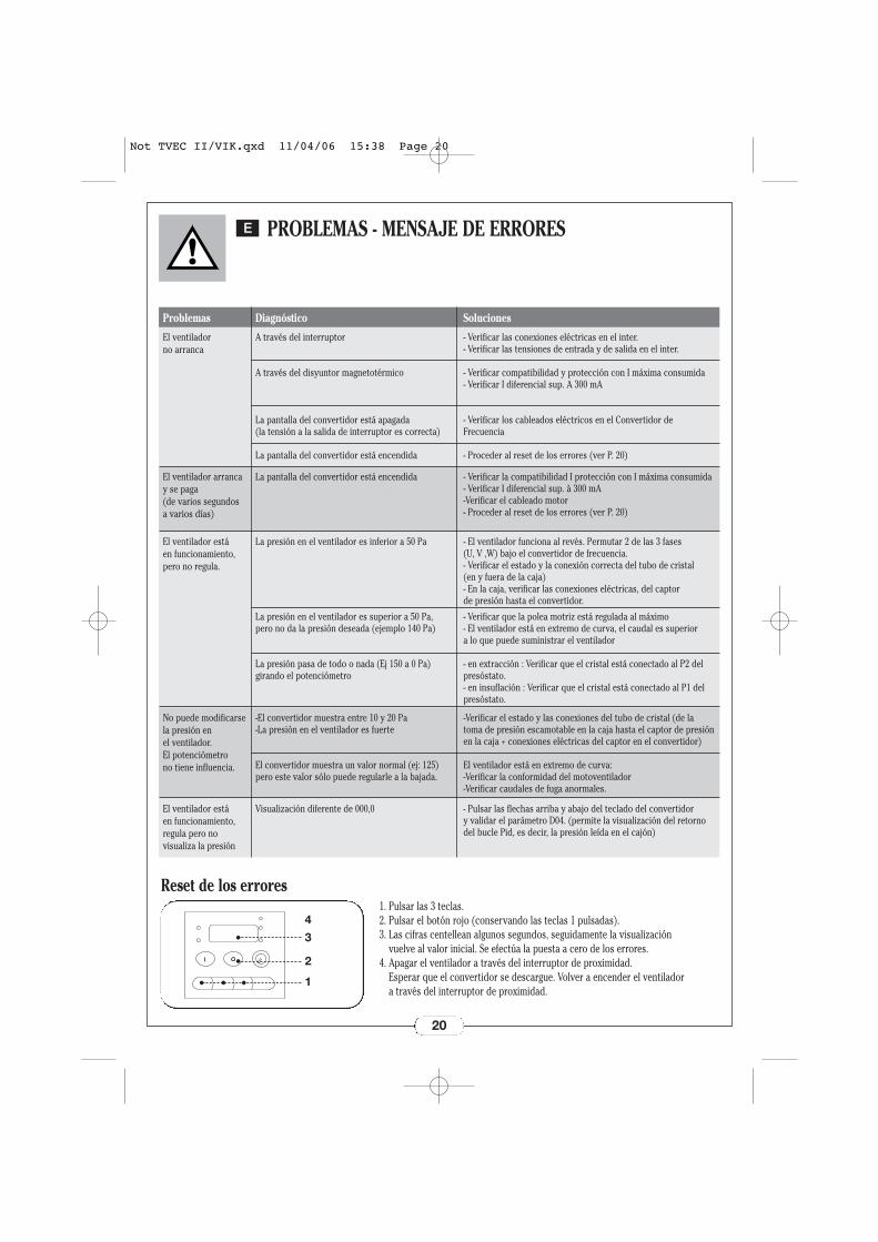
El ventilador no arranca
A través del interruptor
A través del disyuntor magnetotérmico
La pantalla del convertidor está apagada (la tensión a la salida de interruptor es correcta)
La pantalla del convertidor está encendida
- Verificar las conexiones eléctricas en el inter.- Verificar las tensiones de entrada y de salida en el inter.
- Verificar compatibilidad y protección con I máxima consumida - Verificar I diferencial sup. A 300 mA
- Verificar los cableados eléctricos en el Convertidor deFrecuencia
- Proceder al reset de los errores (ver P. 20)
Problemas Diagnóstico Soluciones
El ventilador arrancay se paga (de varios segundos a varios días)
La pantalla del convertidor está encendida - Verificar la compatibilidad I protección con I máxima consumida - Verificar I diferencial sup. à 300 mA-Verificar el cableado motor- Proceder al reset de los errores (ver P. 20)
El ventilador está en funcionamiento,pero no regula.
La presión en el ventilador es inferior a 50 Pa
La presión en el ventilador es superior a 50 Pa, pero no da la presión deseada (ejemplo 140 Pa)
La presión pasa de todo o nada (Ej 150 a 0 Pa) girando el potenciómetro
- El ventilador funciona al revés. Permutar 2 de las 3 fases (U, V ,W) bajo el convertidor de frecuencia.- Verificar el estado y la conexión correcta del tubo de cristal (en y fuera de la caja)- En la caja, verificar las conexiones eléctricas, del captor de presión hasta el convertidor.
- Verificar que la polea motriz está regulada al máximo- El ventilador está en extremo de curva, el caudal es superior a lo que puede suministrar el ventilador
- en extracción : Verificar que el cristal está conectado al P2 delpresóstato.- en insuflación : Verificar que el cristal está conectado al P1 delpresóstato.
No puede modificarsela presión en el ventilador. El potenciómetro no tiene influencia.
-El convertidor muestra entre 10 y 20 Pa-La presión en el ventilador es fuerte
El convertidor muestra un valor normal (ej: 125)pero este valor sólo puede regularle a la bajada.
-Verificar el estado y las conexiones del tubo de cristal (de latoma de presión escamotable en la caja hasta el captor de presiónen la caja + conexiones eléctricas del captor en el convertidor)
El ventilador está en extremo de curva:-Verificar la conformidad del motoventilador -Verificar caudales de fuga anormales.
El ventilador está en funcionamiento,regula pero no visualiza la presión
Visualización diferente de 000,0 - Pulsar las flechas arriba y abajo del teclado del convertidor y validar el parámetro D04. (permite la visualización del retornodel bucle Pid, es decir, la presión leída en el cajón)
Reset de los errores1. Pulsar las 3 teclas.2. Pulsar el botón rojo (conservando las teclas 1 pulsadas).3. Las cifras centellean algunos segundos, seguidamente la visualización
vuelve al valor inicial. Se efectúa la puesta a cero de los errores.4. Apagar el ventilador a través del interruptor de proximidad.
Esperar que el convertidor se descargue. Volver a encender el ventilador a través del interruptor de proximidad.
PROBLEMAS - MENSAJE DE ERRORES
20
E
Not TVEC II/VIK.qxd 11/04/06 15:38 Page 20
E01
E02
E03
E04
E05
E09
E14
E15
E08E11E22
E21
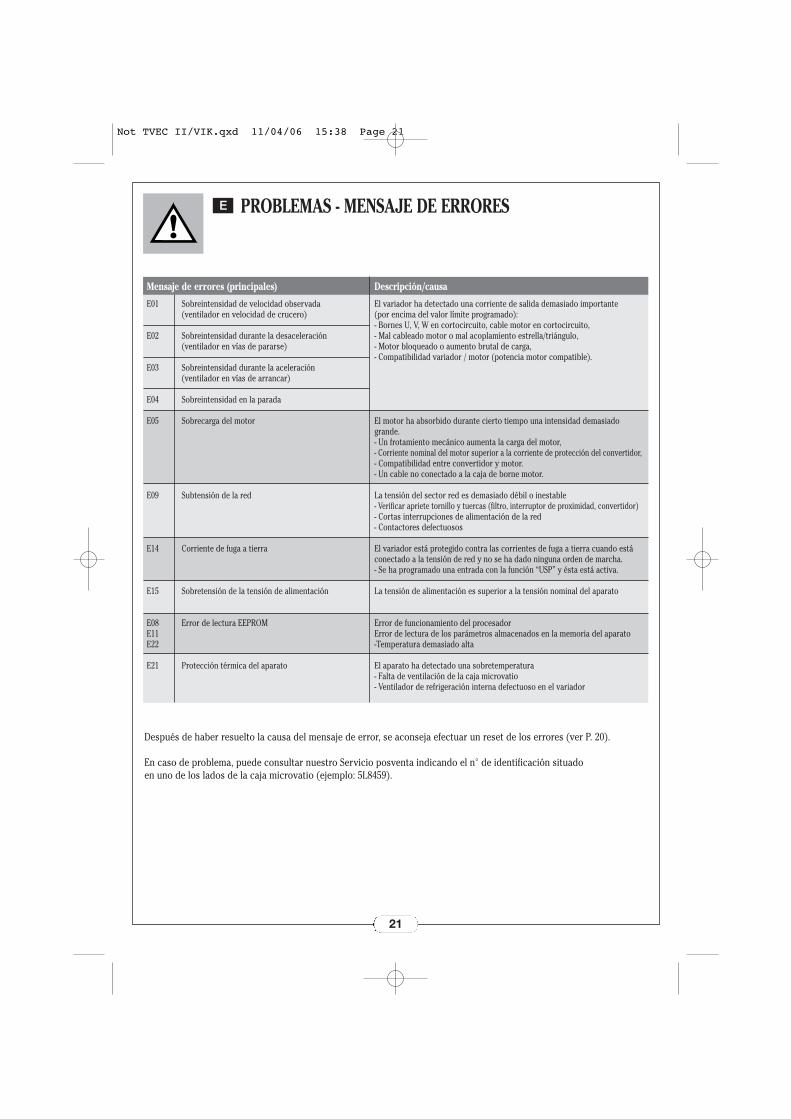
Sobreintensidad de velocidad observada (ventilador en velocidad de crucero)
Sobreintensidad durante la desaceleración (ventilador en vías de pararse)
Sobreintensidad durante la aceleración (ventilador en vías de arrancar)
Sobreintensidad en la parada
Sobrecarga del motor
Subtensión de la red
Corriente de fuga a tierra
Sobretensión de la tensión de alimentación
Error de lectura EEPROM
Protección térmica del aparato
El variador ha detectado una corriente de salida demasiado importante (por encima del valor límite programado):- Bornes U, V, W en cortocircuito, cable motor en cortocircuito,- Mal cableado motor o mal acoplamiento estrella/triángulo,- Motor bloqueado o aumento brutal de carga,- Compatibilidad variador / motor (potencia motor compatible).
El motor ha absorbido durante cierto tiempo una intensidad demasiado grande.- Un frotamiento mecánico aumenta la carga del motor,- Corriente nominal del motor superior a la corriente de protección del convertidor,- Compatibilidad entre convertidor y motor.- Un cable no conectado a la caja de borne motor.
La tensión del sector red es demasiado débil o inestable- Verificar apriete tornillo y tuercas (filtro, interruptor de proximidad, convertidor)- Cortas interrupciones de alimentación de la red- Contactores defectuosos
El variador está protegido contra las corrientes de fuga a tierra cuando estáconectado a la tensión de red y no se ha dado ninguna orden de marcha.- Se ha programado una entrada con la función “USP” y ésta está activa.
La tensión de alimentación es superior a la tensión nominal del aparato
Error de funcionamiento del procesadorError de lectura de los parámetros almacenados en la memoria del aparato-Temperatura demasiado alta
El aparato ha detectado una sobretemperatura- Falta de ventilación de la caja microvatio- Ventilador de refrigeración interna defectuoso en el variador
Mensaje de errores (principales) Descripción/causa
Después de haber resuelto la causa del mensaje de error, se aconseja efectuar un reset de los errores (ver P. 20).
En caso de problema, puede consultar nuestro Servicio posventa indicando el n° de identificación situado en uno de los lados de la caja microvatio (ejemplo: 5L8459).
PROBLEMAS - MENSAJE DE ERRORES
21
E
Not TVEC II/VIK.qxd 11/04/06 15:38 Page 21
22
Not TVEC II/VIK.qxd 11/04/06 15:38 Page 22
Not TVEC II/VIK.qxd 11/04/06 15:38 Page 23
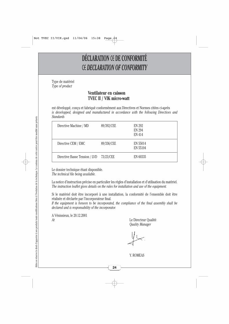
DÉCLARATION CE DE CONFORMITÉCE DECLARATION OF CONFORMITY
24
Type de matérielType of product
Ventilateur en caisson TVEC II / VIK micro-watt
est développé, conçu et fabriqué conformément aux Directives et Normes citées ci-aprèsis developped, designed and manufactured in accordance with the following Directives and Standards
Le dossier technique étant disponible.The technical file being available.
La notice d’instruction précise en particulier les règles d’installation et d’utilisation du matériel.The instruction leaflet gives details on the rules for installation and use of the equipment.
Si le matériel doit être incorporé à une installation, la conformité de l’ensemble doit être réalisée et déclarée par l’incorporateur final.If the equipment is forseen to be incorporated, the compliance of the final assembly shall be declared and is responsability of the incorporator.
A Vénissieux, le 20.12.2001At Le Directeur Qualité
Quality Manager
Y. ROMEAS
Directive Machine / MD 89/392/CEE EN 292EN 294EN 414
Directive CEM / EMC 89/336/CEE EN 55014EN 55104
Directive Basse Tension / LVD 73/23/CEE EN 60335
Alde
s se
rése
rve
le d
roit
d’ap
port
er à
ses p
rodu
its to
ute
mod
ifica
tions
liée
s à l’
évol
utio
n de
la te
chni
que.
Le c
onte
nu d
e ce
tte n
otic
e pe
ut ê
tre m
odifi
é sa
ns p
réav
is.Not TVEC II/VIK.qxd 11/04/06 15:38 Page 24