venanzetti vibrazioni milano srl via de gasperi, 14 - … norme generali di sicurezza .....3 sezione...
TRANSCRIPT

Venanzetti Vibrazioni Milano SrlVia De Gasperi, 14 - 42019 Scandiano (RE) Italia - Tel.+39-0522-851279 - Fax +39-0522-765357Sede legale: Via dell’Annunciata, 21 - Milano
IT Oscillatori meccanici USO E MANUTENZIONEEN Linear motion exciters USE AND MAINTENANCEFR Excitateurs à balourds UTILISATION ET ENTRETIENDE Unwucht-Erreger GEBRAUCH UND WARTUNGES Excitadores desequilibrado USO Y MANUTENCIONPrima di iniziare ad operare con il vibratore, leggere attentamente il manuale di uso e manutenzioneCarefully read the use and maintenance manual before beginning to work with the vibrator.Avant de commencer à opérer avec le vibrateur, lisez attentivement le manuel d’utilisation et d’entretien.Bevor man beginnt, den Unwuchtmotor zu benutzen, ist die Betriebs- und Wartungsanleitung aufmerksam duchzulesen.Antes de iniciar a trabajar con el vibrador, leer con atención el manual de uso y mantenimiento.
055114301/01/2010

2
ITALIANO ITALIANO
SEZIONE 1 - Descrizione e caratteristiche principali
1.0 PRESENTAZIONEQuesto manuale riporta le informazioni, e quanto ritenuto necessario per la conoscenza, l’installazione, il buon uso e la normale manutenzione degli Oscillatori Meccanici Serie VMD prodotti dalla Venanzetti Vibrazioni Milano s.r.l. di Scandiano (Reggio Emilia) Italia. Quanto riportato non costituisce una descrizione completa dei vari organi nè una esposizione dettagliata del loro funzionamento, però l’utente troverà quanto è normalmente utile conoscere per una corretta installazione, un buon uso in sicurezza e per una buona conservazione del prodotto.Dall’osservanza di quanto prescritto, dipende il regolare funzionamento, la durata e l’economia di esercizio del prodotto.La mancata osservanza delle norme descritte in questo opuscolo, la negli-genza ed un cattivo e inadeguato uso del prodotto, possono essere causa di annullamento, da parte della Venanzetti, della garanzia che essa dà al prodotto stesso. Al ricevimento dell’oscillatore controllare che:- L’imballaggio, se previsto, non risulti deteriorato al punto di aver
danneggiato il motovibratore;- La fornitura corrisponda alle specifiche dell’ordine (vedere quanto
trascritto nel Documento di Trasporto);- Non vi siano danni esterni.In caso di fornitura non corrispondente all’ordine o in presenza di danni esterni al prodotto informare immediatamente, dettagliatamente, sia lo spedizioniere che la Venanzetti o il suo rappresentante di zona.Smaltire i materiali di imballo conformemente alle disposizioni sullo smalti-mento vigenti sul luogo.
INDICESEZIONE 1: Descrizione e caratteristiche principali .............................. 21.0 Presentazione ................................................................................ 21.1 Garanzia ........................................................................................ 21.2 Identificazione ................................................................................ 21.3 Descrizione dell’oscillatore ............................................................ 21.4 Destinazione d’uso dell’oscillatore ................................................. 31.5 Caratteristiche tecniche ................................................................. 3
SEZIONE 2: Norme di sicurezza ............................................................ 32.0 Sicurezza ....................................................................................... 32.1 Norme generali di sicurezza .......................................................... 3
SEZIONE 3: Movimentazione e installazione......................................... 43.0 Movimentazione ............................................................................ 43.1 Prima dell’installazione .................................................................. 43.2 Installazione ................................................................................... 4
SEZIONE 4: Regolazione dell’intensitΰ delle vibrazioni ......................... 44.0 Variazione del momento statico ..................................................... 44.1 Montaggio masselli aggiuntivi ........................................................ 54.2 Rimozione masselli aggiuntivi ....................................................... 54.3 Montaggio coperchi masse ............................................................ 5
SEZIONE 5: Lubrificazione .................................................................... 65.0 Primo inserimento olio lubrificante ................................................. 65.1 Tempi per il cambio olio ................................................................. 65.2 Cambio olio lubrificante ................................................................. 6
SEZIONE 6: Accoppiamenti e motore di azionamento .......................... 76.0 Accoppiamento di un singolo oscillatore ....................................... 76.1 Accoppiamento di oscillatori in serie ............................................. 7
SEZIONE 7: Manutenzione e parti di ricambio....................................... 77.0 Manutenzione ................................................................................ 77.1 Parti di ricambio ............................................................................. 7
CARATTERISTICHE TECNICHE: ...................................................... 32 .Dimensioni di ingombro ........................................................................ 32Interassi di fissaggio e coppie di serraggio........................................... 33Dati tecnici: momento statico e cuscinetti........................................ 34-35Tabelle livello olio............................................................................. 36-37Caratteristiche olio lubrificante ............................................................. 38Tavola per parti di ricambio................................................................... 39Descrizione parti di ricambio ........................................................... 40-41Giunti di accoppiamento e potenze motori di azionamento .................. 42Accoppiamento di oscillatori ................................................................. 43
Dichiarazione di incorporazione (Direttiva 2006/42/CE) ................. 44
La Venanzetti, è comunque a completa disposizione per assicurare una pronta ed accurata assistenza tecnica e tutto ciò che può essere utile per il miglior funzionamento ed ottenere il massimo della resa dall’oscillatore.
1.1 GARANZIALa Ditta Costruttrice, oltre a quanto riportato sul contratto di fornitura, garan-tisce i suoi prodotti per un periodo di 12 (dodici) mesi dalla data di consegna. Tale garanzia si esplica unicamente nella riparazione o sostituzione gratuita di quelle parti che, dopo un attento esame effettuato dall’ufficio tecnico della Ditta Costruttrice, risultano difettose. La garanzia, con esclusione di ogni responsabilità per danni diretti o indiretti, si ritiene limitata ai soli difetti di materiale e cessa di avere effetto qualora le parti rese risultassero comunque smontate, manomesse o riparate al di fuori della fabbrica. Rimangono altresμ esclusi dalla garanzia i danni derivanti da negligenza, incuria, cattivo utilizzo e uso improprio del prodotto o da errate manovre dell’operatore ed errata installazione.La rimozione dei dispositivi di sicurezza, di cui il prodotto è dotato, farà decadere automaticamente la garanzia e le responsabilità della Ditta Costruttrice. La ga-ranzia decade inoltre qualora fossero usate parti di ricambio non originali. L’attrezzatura resa, anche se in garanzia dovrà essere spedita in Porto Franco.
1.2 IDENTIFICAZIONEIl numero di matricola dell’oscillatore è stampigliato sull’apposita targhetta di identificazione. Tale targhetta, riporta:DATI RELATIVI ALL’OSCILLATOREA) Tipo di oscillatore;B) Serie dell’oscillatore (identifica eventuali aggiornamenti sul
prodotto);C) Massimo momento statico e corrispondenti n° di giri RPM massimo,
forza centrifuga e peso dell’oscillatore;D) Minimo momento statico e corrispondenti n° di giri RPM massimo,
forza centrifuga e peso dell’oscillatore;E) Numero di matricola.DATI RELATIVI AL MOTORE CHE AZIONA L’OSCILLATOREF) Potenza nominale.
1.3 DESCRIZIONE DELL’OSCILLATORE4
5
1
6
3
2
A
C
D
B
E
F
Descrizione Fig. 1 :1 Carcassa;2 Piedini d’appoggio e di fissaggio3 Masse eccentriche;4 Coperchio protezione masse eccentriche;5 Staffe di aggancio per il sollevamento e sicurezza;6 Coperchio ingranaggi.
Fig. 1

3
ITALIANO ITALIANOGli oscillatori meccanici Venanzetti sono costruiti con una carcassa in ghisa sferoidale che, tramite 4 cuscinetti, sostiene due alberi accoppiati mediante due ingranaggi elicoidali. Alle estremità degli alberi sono montate masse eccentriche con momento variabile tramite l’inserimento di masselli aggiuntivi in acciaio o in piombo.Gli ingranaggi all’interno del corpo sono lubrificati sia per immersione in olio sia per esposizione a nebbia d’olio.Grazie all’accoppiamento degli alberi tramite ingranaggi le masse eccentriche sui due alberi ruotano sincronizzate in senso opposto, determinando una forza centrifuga risultante unidirezionale perpendicolare al piano di appoggio dell’oscillatore.Il moto viene trasmesso ad uno dei due alberi (albero conduttore) da un sistema di azionamento esterno che si collega all’albero tramite giunto, generalmente cardanico.L’azionamento esterno può essere costituito da un motore (elettrico o altro) collegato direttamente o tramite cinghie e pulegge, ecc.L’azionamento esterno può essere a giri variabili con valori minimo e massimo in base alle caratteristiche dello specifico oscillatore.Per incrementare la forza centrifuga ottenibile da un singolo oscillatore è possibile effettuare un collegamento in serie di più oscillatori uguali fra di loro, tramite accoppiamento degli alberi di trascinamento.
1.4 DESTINAZIONE D’USO DELL’OSCILLATOREGli oscillatori elencati nel presente libretto sono sono stati progettati e costruiti esclusivamente per impieghi su macchine vibranti.Tale oscillatore, non può essere messo in servizio prima che la macchina, in cui sarà incorporato, sia stata dichiarata conforme alle disposizioni della Direttiva 2006/42/CE e successive modifiche.Nell’ambito della Direttiva 2006/42/EC gli oscillatori meccanici VMD rientrano nella definizione di “quasi macchina”.L’utilizzo dello stesso per impieghi diversi da quelli previsti e non conformi a quanto descritto in questo opuscolo, oltre ad essere con-siderato improprio e vietato, scarica la Ditta Costruttrice da qualsiasi responsabilità diretta e/o indiretta.
1.5 CARATTERISTICHE TECNICHEPer le «Caratteristiche tecniche» dei singoli oscillatori, vedere tabelle specifiche a partire da pag. 32.
SEZIONE 2 - Norme di sicurezza
2.0 SICUREZZA
Si consiglia di leggere molto attentamente questo manuale ed in particolare le norme di sicurezza, facendo molta attenzione a quelle operazioni che risultano particolarmente pericolose.La Ditta Costruttrice declina ogni e qualsiasi responsabilità per la mancata osservanza delle norme di sicurezza e di prevenzione infor-tuni di seguito descritte. Declina inoltre ogni responsabilità per danni causati da un uso improprio dell’oscillatore o da modifiche eseguite senza autorizzazione.
Fare attenzione al segnale di pericolo presente in questo manuale; esso precede la segnalazione di un potenziale pericolo.
2.1 NORME GENERALI DI SICUREZZAPrima di utilizzare l’oscillatore pertanto leggere attentamente e memo-rizzare le seguenti norme sulla sicurezza. Dopo la lettura, conservare con cura il presente manuale.
Prima di effettuare qualsiasi operazione sull’oscillatore è assolutamente obbligatorio studiare e memorizzare tutte le informazioni contenute nel presente manuale.- Devono essere assolutamente rispettate le norme sulla sicurezza e le
norme anti-infortunistiche generali e locali del luogo di installazione.
- Tutte le persone che possono operare nella zona in cui è installato l’oscil-latore devono essere messe a conoscenza delle informazioni contenute nel presente libretto.
- ll personale destinato ad eseguire operazioni di manutenzione e ripara-zione sugli oscillatori deve essere personale qualificato e addestrato da parte del costruttore della macchina. Tale personale deve essere messo a conoscenza delle informazioni contenute nel presente libretto.
ATTENZIONE: Quando si effettuano operazioni sull’oscillatore meccanico è possibile che le masse eccentriche ruotino sul proprio asse con conseguente rischio di colpi e schiacciamento.
- Mantenere pulita e in ordine la zona di lavoro. Aree e ambienti in disordine favoriscono il verificarsi di incidenti.
- Prima di iniziare il lavoro, controllare la perfetta integrità dell’oscillatore e della macchina stessa su cui è applicato. Controllare il regolare funzionamento e che non vi siano elementi danneggiati o rotti. Le parti che risultassero danneggiate o rotte devono essere riparate o sostituite da personale competente e autorizzato.
- Riparare, o far riparare da personale non autorizzato dalla Ditta Costrut-trice, significa, oltre a perdere la garanzia, operare con attrezzature non sicure e potenzialmente pericolose.
- Non toccare l’oscillatore durante il funzionamento.- Qualsiasi tipo di verifica, controllo, pulizia, manutenzione, cambio e
sostituzione pezzi, deve essere effettuata con oscillatore fermo. Il motore elettrico di azionamento deve essere spento con spina staccata dalla presa di corrente.
- Si fa assoluto divieto di far toccare o far utilizzare l’oscillatore a bambini e a persone estranee, inesperte o non in buone condizioni di salute.
- Verificare che l’impianto di alimentazione del motore di azionamento sia conforme alle norme.
- Se l’installazione di un oscillatore su di una macchina fosse causa di superamento del livello sonoro, stabilito dalle norme vigenti nel Paese di utilizzo, è necessario che gli addetti si muniscano di protezioni adatte, tipo cuffie, per la salvaguardia dell’udito.
- Una copia integrale del presente libretto deve sempre accompagnare la documentazione della macchina vibrante su cui è installato l’oscillato-re.
- Una copia integrale del presente libretto deve sempre essere disponibile nelle vicinanze dell’oscillatore stesso.
- Anche se gli oscillatori sono progettati per funzionare a bassa temperatura d’esercizio, in ambienti particolarmente caldi la temperatura degli stessi può raggiungere valori elevati indotti dall’ambiente stesso.
Attendere pertanto il raffreddamento prima di intervenire sul oscillatore.
ATTENZIONE: In funzionamento l’oscillatore meccanico contiene olio lubrificante ad alta temperatura. Attendere il raffreddamento prima di intervenire sull’oscillatore.
- Devono essere usati solo gli utensili autorizzati e descritti nelle istruzioni d’uso o riportati nei cataloghi della Ditta Costruttrice. Non osservare questi consigli significa operare con attrezzature insicure e potenzialmente pericolose.
- Le riparazioni devono essere effettuate da personale autorizzato dalla Ditta Costruttrice. La Ditta Costruttrice è comunque a completa disposizione per assicurare un’immediata e accurata assistenza tecnica e tutto ciò che può essere necessario per il buon funzionamento e la massima resa dell’oscillatore.
- L’utilizzatore deve impedire che persone o corpi estranei vengano a contatto con le masse eccentriche durante il funzionamento.
ATTENZIONE: È severamente vietato utilizzare l’oscillatore VMD in atmosfere potenzialmente esplosive.

4
ITALIANO ITALIANO
SEZIONE 3 - Movimentazione e installazione
3.0 MOVIMENTAZIONEL’oscillatore può essere fornito privo di imballo o pallettizzato a seconda del tipo e della dimensione.Per la movimentazione del gruppo, se pallettizzato, usare un carrello ele-vatore o transpallet a forche, se privo d’imballo utilizzare esclusivamente i fori di sollevamento.
Nella movimentazione del gruppo prestare massima cura affinchι non sia assoggettata ad urti o vibrazioni onde evitare danneggiamenti ai cuscinetti volventi.Per agganciare e sollevare gli oscillatori meccanici utilizzare solamente i fori previsti nella carcassa dell’oscillatore.Per agganciare e sollevare gli oscillatori meccanici non utilizzare mai le masse, gli alberi o i coperchi masse.
Fare attenzione al peso massimo dell’oscillatore indicato in targhet-ta, gli apparecchi di sollevamento e movimentazione devono essere dimensionati per quel peso.Per il peso dei diversi oscillatori vedere anche pagine 34-35. L’oscillatore meccanico deve essere appoggiato esclusivamente sulla sua base di fissaggio.
3.1 PRIMA DELL’INSTALLAZIONEPrima dell’installazione, se l’oscillatore è rimasto immagazzinato per un lungo periodo, controllare a mano che gli alberi ruotino liberamente.
Se dal controllo risultassero anomalie, l’oscillatore deve essere inviato ad un Centro di Assistenza Venanzetti oppure alla Venanzetti stessa, per il ripristino dell’efficienza.
Gli oscillatori meccanici vengono forniti privi di olio. NON inserire olio prima che l’oscillatore sia montato sulla macchina nella sua posizione definitiva.
3.2 INSTALLAZIONE
Gli oscillatori meccanici non possono essere azionati fino a quando non è stato introdotto l’olio lubrificante.
Gli oscillatori meccanici possono essere montati solo con gli alberi in posizione orizzontale.
L’oscillatore meccanico deve essere fissato ad una struttura perfettamente piana ed in modo rigido con bulloni (qualità 8.8 - DIN 931-933) e dadi (qualità 8.8 - DIN 934) o dadi autobloccanti (DIN 982-985) in grado di sop-portare elevate coppie di serraggio. Utilizzare a tal proposito una chiave dinamometrica regolata secondo quanto riportato nella tabella “Coppie di serraggio” a pag.33.Il diametro del bullone, in base al tipo di oscillatore da installare, deve corrispondere a quello indicato nelle tabelle da pag. 33. È indispensabile inoltre, controllare che i bulloni siano serrati a fondo. Tale controllo è particolarmente necessario durante il periodo iniziale di funzionamento.Indipendentemente dal tipo di oscillatore, le coppie di serraggio delle viti di fissaggio dell’oscillatore alla struttura devono essere le seguenti:
Vite 8.8 Coppia di serraggio Nm ft·lbsM24 710 513M30 1150 830M36 1900 1370
Ricordarsi che la maggior parte delle avarie e dei guasti è dovuta a fissaggi irregolari o a serraggi mal eseguiti.
Ricontrollare il serraggio dopo un breve periodo di funzionamento, circa 50 ore.
Si consiglia poi successivi controlli ogni 1000 ore.
ATTENZIONE: l’utilizzo di viti o dadi non adatti oppure il serraggio non corretto può provocare la caduta dell’oscillatore e gravi danni alla macchina e alla salute delle persone.
Si consiglia di fissare l’oscillatore installato ad un cavo di sicurezza in acciaio, di opportuno diametro e di lunghezza tale a sostenere, causa accidentale distacco, l’oscillatore stesso, con caduta massima di 15 cm (6”).
Attenzione: Non effettuare saldature alla struttura con l’oscillatore montato e collegato. La saldatura potrebbe causare danni ai cuscinetti.
Una volta che l’oscillatore è fissato in modo definitivo sulla macchina vibrante occorre spostare il tappo di sfiato nella posizione idonea indicata nelle figure 1,2,3,4 a pag.36, in base alla posizione dell’oscillatore rispetto all’orizzontale. Per la posizione 180° (fig.3 pag.36) è necessario montare il tappo vetro in uno dei punti D.
Solo dopo aver posizionato il tappo di sfiato nella corretta posizione, ed il tappo vetro solo nel caso di oscillatore in posizione 180°, è possibile effettuare l’inserimento dell’olio lubrificante.
Gli oscillatori meccanici vengono forniti privi di olio. Da oscillatore nuovo, per il primo inserimento di olio lubrificante seguire le indicazioni al paragrafo 5.0.
Ricordare di fare funzionare per brevi periodi gli oscillatori quando si eseguono le messe a punto onde evitare danni all’oscillatore e alla struttura in caso di anomalie.
SEZIONE 4 - Regolazione dell’intensità delle vibrazioni
4.0 VARIAZIONE DEL MOMENTO STATICO
ATTENZIONE: Questa operazione deve essere eseguita rigorosamente da personale specializzato e con motore elettrico di azionamento ad alimentazione disinserita.
- Per la regolazione dell’intensità delle vibrazioni è necessario togliere i coperchi delle masse.
- Ciascuna massa eccentrica è prevista per alloggiare masselli aggiuntivi che possono essere in acciaio o in piombo.
ATTENZIONE: Al termine della propria vita utile l’oscillatore ed ogni sua parte deve essere smaltito separatamente dagli altri rifiuti e nel rispetto delle leggi e dei regolamenti vigenti nel paese d’uso.
- Dalle tabelle a pag.34-35 si vedano per ogni oscillatore i valori del momento statico in funzione dei pesi aggiuntivi. L’utilizzatore deve stabilire il momento statico di cui necessita sulla macchina vibrante e realizzare la configurazione opportuna con i masselli aggiuntivi.
- I pesi aggiuntivi devono essere montati sempre in posizione simmetrica rispetto alla mezzeria delle masse eccentriche. Per ciascun oscillatore le 4 masse eccentriche devono essere equipaggiate con gli stessi masselli aggiuntivi.
ATTENZIONE: Se su una macchina vibrante vengono installati più oscillatori in serie, tutti gli oscillatori devono avere lo stesso momento statico, ovvero la stessa configurazione di masse aggiuntive.

5
ITALIANO ITALIANOLa fornitura, in accordo con il cliente, può essere fatta priva di masselli aggiuntivi o con masselli aggiuntivi.
4.1 MONTAGGIO MASSELLI AGGIUNTIVI
ATTENZIONE: Questa operazione deve essere eseguita rigorosamente da personale specializzato e con motore elettrico di azionamento ad alimentazione disinserita.
ATTENZIONE: Quando si lavora sull’oscillatore le masse eccentriche possono muoversi e di conseguenza vi è pericolo di urti.
ATTENZIONE: Il montaggio dei masselli aggiuntivi provoca la rotazione delle masse eccentriche, fare attenzione agli urti che ne possono derivare.
Per il montaggio dei masselli aggiuntivi procedere nella sequenza indicata:- Sulle masse eccentriche verificare che siano liberi sia i fori di inserimento
dei masselli, sia i fori radiali per le spine elastiche di fissaggio dei masselli stessi.
- Inserire il massello nel foro in modo tale che il foro radiale del massello coincida con il foro radiale della massa eccentrica.
- Spingere il massello nel foro fino al completo inserimento nella massa eccentrica, a questo punto i fori radiali di massa e massello devono coincidere.
- Infilare la spina elastica di fissaggio nel foro radiale della massa eccentrica, fino a quando la spina è entrata completamente nel diametro della massa eccentrica.
1 - massello aggiuntivo2 - spina elastica di fissaggio
4.2 RIMOZIONE MASSELLI AGGIUNTIVI
ATTENZIONE: Questa operazione deve essere eseguita rigorosamente da personale specializzato e con motore elettrico di azionamento ad alimentazione disinserita.
ATTENZIONE: Quando si lavora sull’oscillatore le masse eccentriche possono muoversi e di conseguenza vi è pericolo di urti.
ATTENZIONE: La rimozione dei masselli aggiuntivi provoca la rotazione delle masse eccentriche, fare attenzione agli urti che ne possono derivare.
Procedere nella sequenza indicata:- Smontare per primi i masselli aggiuntivi dalle masse sull’albero lungo.- Spingere una spina elastica di fissaggio radialmente dentro al massello
da togliere.- Ruotare le masse in modo tale che non ci sia sovrapposizione del massello
aggiuntivo con la massa dell’albero corto.- Con colpi leggeri in direzione del corpo oscillatore spingere fuori il mas-
sello.- Togliere la spina elastica di fissaggio.
- I masselli aggiuntivi sulle masse dell’albero corto devono essere espulsi allo stesso modo ma verso l’esterno, in direzione opposta al corpo del-l’oscillatore.
1 - massello aggiuntivo2 - spina elastica di fissaggio
4.3 MONTAGGIO COPERCHI MASSE
ATTENZIONE: Prima della messa in funzione dell’oscillatore è assolutamente indispensabile montare i coperchi masse a protezione delle stesse. Il funzionamento senza coperchi masse costituisce un rischio per la macchina e per la salute delle persone.
I coperchi masse si compongono di 3 parti dal lato accoppiamento e di 4 parti dal lato senza accoppiamento:- 1 - scatola protezione masse - 2 - chiusura inferiore- 3 - chiusura laterale - 4 - protezione albero.La fornitura standard prevede il lato accoppiamento a destra rispetto alla targa di identificazione. L’utilizzatore può invertire il lato accoppiamento semplicemente spostando dall’altro lato la posizione della protezione 4.In caso di accoppiamento di due o più oscillatori in serie l’utilizzatore deve, per ogni oscillatore aggiunto, rimuovere la protezione 4 e installare il kit seconda uscita disponibile su richiesta.
ATTENZIONE: Per una corretta protezione delle masse è necessario che i coperchi masse vengano montati con tutte le parti componenti.Altrimenti ne risulterebbe un pericolo per le persone.
ATTENZIONE: Nel montaggio dei coperchi masse assicurarsi che tutte le viti siano serrate con apposita chiave dinamometrica secondo le coppie indicate di seguito:
Vite 8.8 Coppia di serraggio Nm ft·lbsM10 47 35 M12 78 58M14 128 94M16 186 137M18 265 195M20 373 275

6
ITALIANO ITALIANO
SEZIONE 5 - LUBRIFICAZIONE
5.0 PRIMO INSERIMENTO OLIO LUBRIFICANTE
Gli oscillatori meccanici vengono forniti privi di olio di lubrificazione. Prima di mettere in funzione l’oscillatore occorre pertanto introdurre l’olio lubrificante.
Prima di inserire l’olio lubrificante fissare il tappo a sfiato nella posizione idonea indicata nelle figure 1,2,3,4 a pagina 36, in base alla posizione dell’oscillatore rispetto all’orizzontale.Prima di inserire l’olio lubrificante per la posizione 180° (fig.3 pag.36) è anche necessario fissare il tappo vetro in uno dei punti D.
L’inserimento dell’olio nell’oscillatore è a cura dell’utilizzatore.Tale operazione deve essere eseguita con motore elettrico di aziona-mento ad alimentazione disinserita.
La quantità di olio da introdurre dipende dall’angolo di inclinazione dell’oscillatore sulla macchina rispetto al piano orizzontale (si veda tabella alla pag.37). Il livello dell’olio viene determinato con l’utilizzo dell’asta livello olio fornita insieme all’oscillatore.Mantenere tale asta sempre in prossimità della macchina vibrante e dell’oscillatore.
Il tipo di olio consigliato dipende dalla temperatura di esercizio dell’oscillatore o dalla temperatura ambiente, nella tabella di pag.38 sono indicati i diversi tipi di olio con alcuni suggerimenti per diverse marche produttrici di olio.
Utilizzare solamente oli lubrificanti di buona qualità conformi alle norme. Per i diversi tipi di oscillatore, in base alla inclinazione dell’oscillatore stesso rispetto al piano orizzontale, spostare i dadi dell’asta in modo da fissare le posizioni X e Y come da tabella di pag.37. Per esempio per l’oscillatore tipo VMD 23000/6 con inclinazione di montaggio di +75° (vedi pag.36), la quota X sull’asta deve essere 557mm mentre la quota Y deve essere 22mm.Dalle figure1, 2, 3, 4 a pag. 36, corrispondenti alle diverse posizioni dell’oscillatore, si evidenziano i seguenti punti:A - Tappo di sfiatoB - Asta livello olioC - Tappo di scarico olioD - Tappo livello olio visivo. Da utilizzare solo nella posizione 180°: togliere il tappo da uno dei 2 punti D e sostituirlo con il tappo a vetro fornito in dotazione;inserire olio finchè arriva a superare il livello del tappo a vetro.Dalla figure 1, 2, 3, 4 a pag. 36 si evidenziano le diverse posizioni da utilizzare per l’asta livello olio, svitare il tappo in posizione corrispondente ed inserire l’asta livello olio.
Dallo stesso foro per l’asta livello olio inserire l’olio fino a quando il livello non raggiunge i dadi sull’asta:
5.1 TEMPISTICA CAMBIO OLIO LUBRIFICANTE
Si raccomanda il primo cambio olio completo dopo circa 500 ore di funzionamento.
Successivamente si consiglia la sostituzione dell’olio ogni 1000 ore di esercizio o al massimo ogni 3 mesi.
Verificare il livello dell’olio almeno una volta al mese. Se si osserva un livello inferiore al minimo procedere al rabbocco.
La durata dell’oscillatore aumenta con cambi olio più frequenti.
5.2 CAMBIO OLIO LUBRIFICANTEIl foro più basso funge da tappo per lo svuotamento dell’olio, si veda tappo C nelle fig.1,2,3,4 a pag.36 in base all’inclinazione di montaggio dell’oscil-latore.Aprire il tappo e raccogliere l’olio usato attendendo il completo svuotamento dell’oscillatore.I tappi sono magnetici al fine di raccogliere le particelle metalliche derivanti dai contatti degli ingranaggi. Prima di riavvitare i tappi pulire gli stessi dalle particelle metalliche.
ATTENZIONE: Sostituire le guarnizioni di tenuta ogni volta che si svitano i tappi magnetici o a sfiato. Altrimenti sussiste il pericolo di perdita olio e conseguente distruzione dell’oscillatore.
A svuotamento effettuato richiudere i tappi a vite.
Qualora l’olio esausto si presenti in condizioni pessime si consiglia di ridurre l’intervallo di sostituzione. Infatti le scadenze sopra riportate sono puramente indicative, la durata dell’olio dipende dal tipo di olio utilizzato e dalle condizioni di temperatura di lavoro. Farsi consigliare anche dal fornitore dell’olio.
ATTENZIONE: Lo smaltimento dell’olio usato deve avvenire nel rispetto delle Leggi e Regolamenti vigenti nel paese di utilizzo, con particolare riferimento alle Leggi in materia di tutela ambientale e inquinamento.
Immettere l’olio nuovo seguendo le stesse indicazioni al paragrafo 5.0.
ATTENZIONE: L’asta di livello è usata solo per il controllo del livello olio e deve essere sostituita daun tappo per poter far funzionare l’oscillatore.
ATTENZIONE: Non mescolare olio sintetico con olio minerale.
ATTENZIONE: Assicurarsi che l’olio introdotto sia nuovo, conforme alle specifiche come descritto al paragrafo 5.0 ed esente da contaminazioni.
ATTENZIONE: Prima di passare da un tipo di olio ad un altro assicurarsi del completo svuotamento dell’oscillatore. Non effettuare rabbocchi con un olio diverso da quello presente nell’oscillatore. La miscelazione di sue olii diversi può determinare il peggioramento delle specifiche di entrambi gli olii.
ATTENZIONE: Qualora il livello di olio scenda al punto tale da non bagnare l’asta di livello, l’oscillatore non è più correttamente lubrificato e quindi è a rischio di rottura.
ATTENZIONE: Non immettere olio sopra al livello descritto al paragrafo 5.0. Un eccesso di olio può determinare surriscaldamento e danneggiamento dei cuscinetti.
LIVELLO OLIO

7
ITALIANO ITALIANOIl livello dell’olio può essere controllato dopo circa 30 minuti dall’arresto dell’oscillatore.
SEZIONE 6 - Accoppiamenti e motore di azionamento
6.0 Accoppiamento di un singolo oscillatoreL’oscillatore viene fornito, se non diversamente concordato con il cliente) con una flangia di accoppiamento a norme DIN montato sull’albero conduttore (di trascinamento) per l’accoppiamento con il giunto cardanico e l’albero cardanico del sistema di azionamento:
La fornitura Venanzetti si completa fino alla flangia di accoppiamento. Il giunto cardanico, l’albero e le prolunghe e, in generale, l’intero sistema di azionamento non sono parte integrante della fornitura dell’oscillatore. Venanzetti rimane comunque a disposizione per clienti che necessitano anche della fornitura di giunti, alberi, prolunghe e motore di azionamento.
ATTENZIONE: Si consiglia l’utilizzo di parti di accoppiamento di buona qualità e si raccomanda che tutti gli organi di movimento vengano adeguatamente protetti per evitare danni alle persone.
ATTENZIONE: Prestare attenzione alle caratteristiche tecniche dell’oscillatore in targhetta e nelle tabelle da pag.32. È assolutamente essenziale che vengano rispettate le velocità massime e minime, per evitare danneggiamento dell’oscillatore e possibili danni alle persone.
ATTENZIONE: Le caratteristiche del sistema di azionamento devono essere compatibili con le specifiche dell’oscillatore, in particolare la potenza deve essere almeno pari a quella indicata in targhetta.
Alla pagina 42 sono riportate le misure di riferimento per il giunto di accoppiamento dei vari modelli di oscillatore nonchè le potenze consigliate per il motore di azionamento di ogni singolo oscillatore.
6.1 Accoppiamento di oscillatori in serieAl fine di incrementare la forza centrifuga risultante si possono accoppiare in serie più oscillatori dello stesso tipo.L’accoppiamento deve avvenire come esemplificato nello schema di pag.43, cioè tramite alberi e giunti cardanici.Dopo l’accoppiamento verificare che le masse degli oscillatori siano nella stessa posizione, ovvero in fase fra loro.
ATTENZIONE: Gli oscillatori accoppiati in serie devono avere la stessa regolazione del momento statico, ovvero gli stessi masselli aggiuntivi.
ATTENZIONE: Le caratteristiche del sistema di azionamento devono essere compatibili con il trascinamento di tutti gli oscillatori in serie.Pertanto la coppia del motore di azionamento deve essere in grado di azionare il momento totale degli oscillatori in serie.
Rivolgersi a VENANZETTI per domande e assistenza per l’accoppiamento di oscillatori in serie.
SEZIONE 7 - Manutenzione e parti di ricambio
7.0 MANUTENZIONE
ATTENZIONE: La manutenzione dell’oscillatore deve essere eseguita rigorosamente da personale specializzato e con oscillatore smontato dalla macchina vibrante.
Soltanto tecnici autorizzati possono intervenire sulle parti costituenti l’oscillatore.Prima di intervenire per la manutenzione su un oscillatore attendere che la carcassa dello stesso sia a temperatura non superiore a 40°C ed assicurarsi che il collegamento elettrico del motore di azionamento sia disinserito.In caso di sostituzione di parti, montare esclusivamente ricambi ori-ginali Venanzetti.
ATTENZIONE: Ogni qualvolta si effettuano le operazioni di manutenzione si consiglia la sostituzione di tutte le viti e rondelle elastiche smontate e che il serraggio delle viti avvenga con chiave dinamometrica.
Si ricorda infine che la Ditta Costruttrice è sempre a disposizione per qualsiasi necessità di assistenza e ricambi.
ATTENZIONE: La Venanzetti declina ogni responsabilità per le operazioni di manutenzione svolte da terzi sugli oscillatori, anche se con utilizzo di ricambi originali.
Rispettare le leggi in fatto di ecologia in vigore nel Paese in cui viene utilizzata l’attrezzatura, relativamente all’uso ed allo smaltimento dei prodotti impiegati per la pulizia e la manutenzione dell’oscillatore nonchι osservare quanto raccomanda il produttore di tali prodotti.In caso di smantellamento della macchina, attenersi alle normative anti-inquinamento previste nel Paese di utilizzazione.
ATTENZIONE: Ricordarsi che l’olio lubrificante è un componente estremamente inquinante, procedere allo smaltimento nel rispetto delle Legislazioni vigenti.
7.1 PARTI DI RICAMBIO
ATTENZIONE: Utilizzare solo ricambi originali Venanzetti.
Per la richiesta delle parti di ricambio citare sempre:- Tipo di oscillatore (TYPE rilevabile dalla targhetta).- Serie dell’oscillatore (SERIE rilevabile dalla targhetta).- Numero di matricola (SERIAL NO. dalla targhetta).- Numero della parte di ricambio (rilevabile dalle tavole ricambi a partire
da pag.39) e quantità desiderata.- Indirizzo esatto di destinazione della merce e mezzo di spedizione.La Venanzetti, declina ogni responsabilità per errati invii dovuti a richieste incomplete o confusionarie.

8
ENGLISH ENGLISH
INDEXSECTION 1: Description and main features..............................................81.0 Presentation .......................................................................................81.1 Warranty ...................................................................................81.2 Identification .......................................................................................81.3 Linear motion exciter description .......................................................81.4 Destination of use of the exciter ........................................................91.5 Technical features ..............................................................................9
SECTION 2: Safety regulations.................................................................92.0 Safety .................................................................................................92.1 General safety regulations .................................................................9
SECTION 3: Handling and installation ....................................................103.0 Handling ...........................................................................................103.1 Before installation ............................................................................103.2 Installation ........................................................................................10
SECTION 4: Exciter force adjustment .....................................................104.0 Adjustment of the static moment .....................................................104.1 Additional weights assembling ......................................................... 114.2 Additional weights removal .............................................................. 114.3 Weight covers mounting .................................................................. 11
SECTION 5: Lubrication ..........................................................................125.0 Introducing lubricant oil at the first use ............................................125.1 Time intervals for oil changing .........................................................125.2 Lubricant oil change .........................................................................12
SECTION 6: Exciter coupling and drive motor ........................................136.0 Coupling of a single exciter ..............................................................136.1 Coupling of 2 or more exciters in series ..........................................13
SECTION 7: Maintenance and spare parts .............................................137.0 Maintenance ....................................................................................137.1 Spare parts ......................................................................................13
TECHNICAL FEATURES: ..................................................................32Overall dimensions ..................................................................................32Fixing distances and tightening torques ..................................................33Technical datas: static moment and bearing ...................................... 34-35Oil level tables .................................................................................... 36-37Lubricant oil features ...............................................................................38Spare parts list.........................................................................................39Description of spare parts................................................................... 40-41Coupling flange and drive motor power ..................................................42Coupling of linear motion exciters in series .............................................43 Declaration of incorporation (Directive 2006/42/EC) ..........................44
SECTION 1 – Description and main features
1.0 PRESENTATIONThis manual states the information, and all considered necessary for the understanding, installation, correct use and maintenance of the VMD Series Linear motion exciters manufactured by Venanzetti VIbrazioni Milano srl in Scandiano (Reggio Emilia) Italy. All stated does not make up a complete description of the various elements or a detailed description of their functioning. The user will however find all information normally useful for correct installation, correct, safe use and for good preservation of the exciter.Normal functioning, duration and operating costs of the exciter depends on compliance with the afore-mentioned prescriptions. Lack of compliance with the regulations described in this manual, negligence and an incorrect and inadequate use of the exciter may cause Venanzetti to void the warranty it gives to it. On receipt of the exciter check that:- Packaging, if envisioned, has not deteriorated to the point of
having damaged the exciter;- The supply corresponds to order specifications (see the
shipping document);- There is no external damage to the exciter.If the supply does not correspond to the order or the product is exter-nally damaged, inform both the forwarding agent and Venanzetti or its local representative, immediately. Dispose all packing materials in compliance with local regulations for waste disposal. Venanzetti, is however at complete disposal to ensure quick and accurate technical assistance and for all that may be necessary to improve functioning and to obtain maximum performance from the product.
1.1 WARRANTYThe Manufacturer, as well as that stated in the supply contract, guarantees its products for a period of 12 (twelve) months from the delivery date. This warranty is only applied in the free repair or replacement of those parts which, after careful examination by the Manufacturer’s technical office, result faulty. The warranty, with exclu-sion of all liability for direct or indirect damage, is limited to defects in materials and ceases to have effect whenever the returned parts are disassembled, tampered with or repaired outside of the factory. Damage deriving from negligence, carelessness, incorrect and improper use of the product, incorrect manoeuvres by the operator and incorrect installation are also excluded from the warranty.Removal of the exciter safety devices, will automatically cause the warranty to be forfeited along with liability of the Manufacturer. The warranty is also forfeited whenever non-original spare parts are used. The returned material, even if under warranty must be delivered with carriage paid.
1.2 IDENTIFICATIONThe exciter serial number is embossed on the identification plate. This plate states:DATAS CONCERNING THE EXCITERA) Exciter type;B) Exciter series (identify possible product updates);C) Maximum static moment and correspondent maximum RPM,
centrifugal force and exciter weight;D) Minimum static moment and correspondent maximum RPM,
centrifugal force and exciter weight;E) Serial number.DATAS CONCERNING THE DRIVE MOTORF) Rated power.
1.3 LINEAR MOTION EXCITER DESCRIPTION
A
C
D
B
E
F
Description Fig. 1 :1 Exciter body;2 Support and fixing feet;3 Eccentric weights;4 Eccentric weights protection cover;5 Coupling bracket for lifting and safety;6 Gears cover.
4
5
1
6
3
2
Fig. 1

9
ENGLISH ENGLISHThe Venanzetti linear motion exciters have been designed with a spheroidal cast iron body that, by means of 4 bearings, supports two shafts coupled by two helicoidal gears. The eccentric weights are mounted at the ends of both shafts, the static moment of the eccentric weights it’s adjustable by means of additional weights in steel or lead.The gear inside the exciter body are lubricated for oil immersion and for oil mist lubrication.Due to the shaft coupling by the gears the eccentric weights on the two shafts are rotating synchronized in opposite sense, determining a resulting unidirectional centrifugal force perpendicular to the mounting surface of the exciter.The rotation is obtained by an external driving system coupled with one of the two shafts (driving shaft) by coupling it with a joint, gene-rally a universal joint (Hooke joint or Cardan joint).The external drive can be a motor (electric or other) coupled directly or by belts and pulleys, etc. The external drive can have variable RPM with maximum and minimum values following specifications of the exciter. To increase the centrifugal force obtained by a single exciter, it is possible to couple in series two or more exciters, same type, coupling them by means of the driving shaft.
1.4 DESTINATION OF USE OF THE EXCITERThe exciters listed in this manual have been designed and built for specific needs and relative to use on vibrating machines.This exciter, cannot be commissioned before the machine into which it will be incorporated has been declared in compliance with the dispositions in the 2006/42/EC Directive and successive amendments. In the application field of the 2006/42/EC Directive the VMD linear motion exciters can be considered as “partly completed machinery”.Its use for jobs different from those envisioned and non-conform to that described in this manual, as well as being considered improper and prohibited, releases the Manufacturer from any direct and/or indirect liability.
1.5 TECHNICAL FEATURESSee the specific tables starting from page 32 for the «Technical Features» of the individual exciters.
SECTION 2 – Safety regulations2.0 SAFETY
Careful reading of this manual is highly recommended, the safety regulations in particular. Pay great attention to dangerous operations.The Manufacturer declines all liability for non-compliance to safety regulations and to accident-prevention prescriptions described below. It also declines any responsibility for dama-ge caused by improper use of the product or by unauthorised modifications.
Pay attention to the danger signal present in this manual; it precedes the signal for a potential danger.
2.1 GENERAL SAFETY REGULATIONSBefore using the exciter, carefully read and memorise the fol-lowing safety regulations. After reading, preserve this manual with care.
Before start to operate with the exciter it’s strictly mandatory to study and memorise all informations enclosed in this manual. - All safety regulations and regulations against accidents valid in
the country of use have to be absolutely followed.
- All the people working and operating in the area in which the exciter is installed must be aware of the informations included in this manual.
- The technicians in charge for maintenance and repairing opera-tions of the exciter have to be qualified and trained by the machi-ne manufacturer. These people have to be instructed about the informations included in this manual.
WARNING: When using and working with the exciter, it’s pos-sible that the eccentric weights turn on their axis with danger of knocking or pressing. - Maintain the work area clean and in order. Untidy areas and
environments favour accidents.- Before starting work, check the perfect integrity of the exciter and
the machine to which it is applied. Check normal functioning and that no elements are damaged or broken. The damaged or broke parts must be repaired or replaced by authorised, trained staff.
- Repair, or have repaired by unauthorised staff, means, operating with unsafe and potentially dangerous equipment as well as loosing the warranty.
- Do not touch the exciter when functioning.- Any type of check, control, cleaning, maintenance, change and
piece replacement, must be carried out with the exciter stopped. The drive motor has to be switched off with the plug disconnected from the socket.
- It is prohibited for children, unauthorised persons, unskilled per-sons and persons who are not in good health to touch or use the exciter.
- Check that the plant power supply of the drive motor is in com-pliance with the regulations.
- If the insertion of an exciter onto a machine causes the sound level, established by the regulations in force in the country in which it is to be used, to be exceeded, operators must use adequate protection to protect their hearing e.g. earphones.
- A complete copy of this manual has always to be included in the documents of the vibrating machine on which the exciter is installed.
- A complete copy of this manual has always to be available in the closeness of the exciter.
- Even if exciters are planned to work at low temperatures, in parti-cularly hot environments the temperature of the exciters may reach very high values which are induced by the environment itself.
Wait for the exciter cooling before intervening.
WARNING: When working the exciter body contain lubricant oil at high temperature. Wait for the exciter cooling before intervening.
- Only authorised tools that are described in the instructions or shown in the Manufacturers catalogue can be used. Ignoring this advice means operating unsafe and potentially dangerous equipment.
- Repairs must only be carried out by staff authorised by the Manufacturer. The Manufacturer is however at complete di-sposal to ensure immediate and accurate technical assistance and all that is necessary for good functioning and maximum performance of the product.
- The user must prevent persons or foreign bodies from coming into contact with the eccentric weights during functioning.
WARNING: It’s strictly forbidden to use the VMD exciter in po-tentially explosive atmosphere.

10
ENGLISH ENGLISHSECTION 3 – Handling and installation3.0 HANDLINGThe exciter may be supplied without packaging or palletised accor-ding to its type and size.To handle the unit, if palletised, use a forklift truck or transpallet with forks. If it is not packed exclusively use the rods or hoisting eye-bolts.
When handling the unit avoid blows or vibrations to prevent damage to the rolling bearings.To hook and lift the exciters use only the coupling bracket in the body of the exciter.To hook and lift the exciters never use the eccentric weights, the shafts or the weight covers.
Be aware of the exciter weight indicated in the plate, the han-dling and lifting equipments have to be dimensioned for this weight. For the exciter weights see also pages 34-35.The linear motion exciter has to be exclusively leaned by the fixing feet.
3.1 BEFORE INSTALLATIONBefore installation, if the exciter has been stored for a long period of time, check by hands that both shafts turn freely.
If anomalies result from the control, the vibrator must be sent to an Venanzetti Assistance Centre or to Venanzetti itself, for restoration of efficiency.
The exciters are supplied without lubricant oil. DON’T introduce oil before the exciter has been mounted on the vibrating machine in the final position.
3.2 INSTALLATION
The exciters cannot be driven till they have been filled with lubricant oil.
The exciters can be assembled only with the shafts in horizontal position.
The exciter must be fixed to a perfectly flat surface using bolts (quality 8.8 - DIN 931-933) and nuts (quality 8.8 - DIN 934) which are able to support high coupling torques. Use a dynamometric wrench adjusted according to that stated in the “Coupling torque” table on page 33.The diameter of the bolt, on the basis of the type of exciter to install, must correspond to that indicated in the table on page 33. It is also necessary to control that the bolts are tightened fully home. This control is particularly necessary during the initial functioning period.The exciter fixing bolts have to be tightened at the following tor-ques:
Vite 8.8 Coppia di serraggio Nm ft·lbsM24 710 513 M30 1150 830M36 1900 1370
Remember that most damage and faults are due to irregular fixing or badly performed tightening.
Re-control tightening after a brief functioning period, about 50 hours.
We recommend subsequent checks every 1000 hours.
ATTENTION: the use of not suitable bolts and nuts or the not correct tightening can determine the exciter fall and heavy da-mages to the vibrating machine and to the people health. It is advised to fix the installed exciter to a steel safety cable, with opportune diameter and a length that will support the vibrator in the case of its accidental detachment. Max. fall of 15 cm (6”).
Attention: Do not carry out welding to the structure with the exciter mounted and connected. Welding could cause damage to the bearings.
When the exciter is definitively fixed on the vibrating machine it’s necessary to move the breather plug with valve in the suitable position indicated in the figures 1, 2, 3, 4 in page 36, based on the exciter position respect to the horizontal.For 180° position (fig.3 page 36) it’s necessary to place the glass plug in one of the D points.
Only after positioning the breather plug with valve in the correct position, and the glass plug only in case of 180° exciter position, it’s possible to introduce lubricant oil.
Exciters are supplied without lubricant oil. So for a new exciter, for the first oil filling follow the indication in paragraph 5.0.
Remember to allow the exciters to function for brief periods of time during set-up. This prevents damage to the exciters and structure in the case of anomalies.
SECTION 4 – Exciter force adjustment4.0 ADJUSTMENT OF THE STATIC MOMENT
WARNING: This operation must be carried out exclusively by specialised staff and with the drive motor with the power supply disconnected.
- To adjust the exciter force it’s necessary to remove the weight covers.
- Each eccentric weight can be equipped with additional weights in lead or steel.
WARNING: At the end of exciter life, the exciter and all its parts have to be disposed separately from the other general waste and it has to be disposed following the regulations and laws envisioned in the country of use.
- Look at the tables in pages 34-35 for the different static moment values depending by the additional weights assembled on each exciter type. The user has to determine the static moment he needs for the vibrating machine and than obtain this value by a certain configuration with the additional weights.
- Additional weights have to be always mounted in a simmetrical position respect to the middle line of the weights. For all exciter types the eccentric weights have to be assembled with the same additional weights.
ATTENTION: If on a vibrating machine exciters in series are installed, all exciters need to have the same static moment, so the same weight configuration and additional weights.

11
ENGLISH ENGLISHFollowing customer request the exciter can be supplied with or without additional weights.
4.1 ADDITIONAL WEIGHTS ASSEMBLING WARNING: This operation must be carried out exclusively by specialised staff and with the drive motor with the power supply disconnected.
WARNING: When working on the exciter the eccentric weights may turn and so there is knocking danger.
WARNING: Mounting of additional weights can determine the rotation of eccentric weights, pay attention for knocking.
To assemble the additional weights proceed in the following indicated sequency:- Verify on the eccentric weights that both the holes for the additional
weights and the radial holes for the fixing elastic pins are free.- Introduce the additional weight in the hole in such a way that the
radial hole in the additional weight corresponds to the radial hole of the eccentric weight.
- Push the additional weight up to a complete introducing in the eccentric weight, than the radial holes of additional weight and eccentric weight have to correspond.
- Push the fixing elastic pin in the hole of the eccentric weight, till the pin it’s completely into the diameter of the eccentric weight.
1 - additional weight2 - fixing elastic pin
4.2 ADDITIONAL WEIGHTS REMOVAL WARNING: This operation must be carried out exclusively by specialised staff and with the drive motor with the power supply disconnected.
WARNING: When working on the exciter the eccentric weights may turn and so there is knocking danger.
WARNING: Removal of additional weights can determine the rotation of eccentric weights, pay attention for knocking.
Proceed in the following indicated sequency:- Start removing additional weights from the driving shaft.- Push the fixing elastic pin radially inside the additional weight to
be removed.- Rotate the weights in such a way there is no overlapping of the
additional weight with the eccentric weight of the driven shaft.- Remove the additional weight from the eccentric weight by lightly
tapping it.- Remove the fixing elastic pin from the disassembled additional
weight.
1 - additional weight2 - fixing elastic pin.
4.3 WEIGHT COVER MOUNTING WARNING: Before start driving the exciter it’s absolutely ne-cessary to assemble the weight covers to protect the eccentric weights. Drive the exciter without weight covers it’s a risk for the vibrating machine and for the people safety.
The weight covers are composed of 3 parts in the coupling side and of 4 parts in the other side: - 1 - main protection weight box - 2 - lower end cover- 3 - side end cover - 4 - shaft protection.The standard supply of the exciter is with the coupling side at the right respect to the identification plate. The user can invert position of the coupling side, easily moving in the opposite side the shaft protection n°4.In case of coupling of two or more exciters in series the user have, for each added exciter, to remove the protection n°4 and install the second opening kit, available on request.
WARNING: To correctly protect the eccentric weights it’s neces-sary to assemble the weight covers with all their parts. Otherwise it would be a risk for people safety.
WARNING: In the weight cover assembling be aware that all screws are correctly tightened with a suitable dynamometric wrench following the indicated torques:Screw 8.8 Tightening torque Nm ft·lbsM10 47 35 M12 78 58M14 128 94M16 186 137M18 265 195M20 373 275

12
ENGLISH ENGLISH
SECTION 5 – Lubrication5.0 INTRODUCING LUBRICANT OIL AT THE FIRST USE Linear motion exciters are supplied without lubricant oil. Befo-re driving the exciter it’s necessary to introduce the lubricant oil.
Before introducing lubricant oil fix the breather plug with valve in the suitable position indicated in the figures 1, 2, 3, 4 in page 36, based on the exciter position respect to the horizontal.Before introducing lubricant oil, for 180° position (fig.3 page 36) it’s also necessary to place the glass plug in one of the D points.
The user is responsible for introduction of lubricant oil in the exciter. This operation has to be carried out when the power supply of the drive motor is disconnected.
The oil quantity to be introduced in the exciter depends on the angle of inclination of the exciter respect to the horizontal (see table in page 37). The oil level can be determined by using the dipstick supplied together with the exciter.Keep the oil dipstick always in proximity of the vibrating machine and exciter.
The recommended oil type depends on the service temperature of the exciter or on the ambient temperature, in the table at page 38 are indicated different types of oil with some suggestions for different oil manufacturers.
Use only good quality lubricant oil in compliance with relevant standards.
For the different exciter types, following the angle of inclination of the exciter respect to the horizontal surface, move the nuts on the dipstick to set X and Y positions, as in table at page 37.As example for exciter type VMD 23000/6 mounted with an angle of inclination of +75° (see page 36), the X dimension on the dipstick has to be 557mm, while the Y dimension has to be 22mm.From figures 1, 2, 3, 4 in page 36, corresponding to the different exciter positions, are put in evidence the following points:A - Breather plug with valveB - Oil dipstickC - Plug for oil drainD - Glass plug for visual level. To be used only in 180° position:
remove plug from one of the D points and replace it with the glass plug included in the supply; introduce oil till the oil is just over the glass plug.
In the figures 1, 2, 3, 4 at page 36, are shown the different positions to be used for the oil dipstick, unscrew the plug in the corresponding position and introduce the oil dipstick.
From the same hole used for the oil dipstick fill oil till the oil level reach the nuts fixed on the dipstick.
5.1 TIME INTERVALS FOR OIL CHANGING
First oil change recommended after about 500 operating hours.
Subsequently we recommend oil change every 1000 operating hours or maximum three months.
Check oil level at least once a month. If a reduced level is found proceed to fill oil at the correct level.
The exciter life increase with more frequent oil changes.
5.2 LUBRICANT OIL CHANGEThe lowest plug in the exciter body have to be used for oil drain, see plug C in the figures 1, 2, 3, 4 in page 36 for the differents angle of inclination of the exciter when mounted on the machine.Unscrew the oil drain plug and collect old oil waiting the complete exciter emptying.The plugs are magnetics to collect metal particles created by gears contact. Before screwing again the plugs clean them by the metal particles.
ATTENTION: Replace seals every time the plugs are removed. Otherwise there is danger of oil losses and consequent damage to the exciter.
After complete emptying and plugs cleaning, screw again the plugs.
If the old oil is in bad conditions we recommend to reduce the inter-val time for oil change. Infact the mentioned above timing it’s just indicative, the oil life depends by the type of oil used and by the operating temperature. Set time intervals also on consultation with oil manufacturer.
ATTENTION: Old oil disposal have to be carried out in respect of the Laws and Regulations in force in the country of use, with particular reference to the Laws regarding environmental protection and pollution.
Fill new oil following same indications at paragraph 5.0.
ATTENTION: The dipstick is only used to check oil level and must be replaced with a screwed plug for operating the exciter.
ATTENTION: Don’t mix mineral oil with synthetic oil.
ATTENTION: Be sure the filled oil is new, in compliance with the requirements and specifications described in paragraph 5.0 and contamination free by particles and other.
ATTENTION: Before changing from a type of oil to another type, be sure the exciter is completely empty and all old oil has been drained. Don’t mix different oil types in the exciter, oil features get worse in case of oil mixing.
WARNING: When the oil level is lower the minimum oil level detectable by the dipstick, the exciter it’s not anymore correctly lubricated, there is heavy risk of breakage.
ATTENTION: Don’t fill oil over the recommended level described in paragraph 5.0. Too much oil in the exciter can bring to an overheating and damage the bearings.
OIL LEVEL

13
ENGLISH ENGLISHThe oil level shoul be checked by the dipstick about 30 minutes after switching off the exciter.
SECTION 6 – Exciter coupling and drive motor6.0 COUPLING OF A SINGLE EXCITERThe exciter is supplied (if not differently agreed with customer) with a coupling flange according to DIN standard, assembled on the driving shaft for the coupling with an universal joint and the Cardan shaft of the driving system:
The Venanzetti standard supply finish at the coupling flange. The universal joint, the shaft and shaft extensions and, in general, the complete driving system are not part of the exciter supply. Italvibras remain however at complete disposal for customer needing the supply of the joints, shafts, shafts extensions and drive motor.
ATTENTION: Venanzetti recommend to use good quality cou-pling parts and we recommend that all moving parts are suitably protected to avoid people injury.
ATTENTION: Take great care to the exciter technical features indicated in the identification plate and in the tables from page 32. It’s absolutely important to respect maximum and minimum speed to avoid exciter damage and possible people injuries.
ATTENTION: The driving system features have to be suitable for the exciter specifications, in particular the rated power has to be at least as indicated in the identification plate.
In page 42 there are the reference dimensions for the coupling flange of the different exciters types and the recommended rated power for the driving motor.
6.1 COUPLING OF 2 OR MORE EXCITERS IN SERIESTo increase the resulting centrifugal force it’s possible to couple together more exciters in series of the same type.The coupling has to be carried out as shown in the drawing of page 43, so with universal joints and shafts.After the coupling check that the eccentric weights of the exciters are in the same position, thus in phase one each other.
ATTENTION: The exciters coupled in series need to be adjusted at the same static moment, thus the same additional weights.
ATTENTION: The driving system features have to be suitable to drive all exciters in series. Consequently the driving system torque has to be able to drive the resulting static moment of alll exciters in series.
Address to Venanzetti questions and assistance requests to carry out exciters coupling in series.
SECTION 7 – Maintenance and spare parts7.0 MAINTENANCE
ATTENTION: The exciter maintenance have to be strictly carried out by specialised staff and with the exciter dismounted by the vibrating machine.
Only authorised technicians can intervene on the parts that make up the exciter.Before carrying out maintenance on the exciter wait until the temperature of the vibrator case is not above 40° C and ensure that the electrical power supply of the driving motor has been disconnected.If parts must be replaced, only Venanzetti original spare parts must be used.
ATTENTION: Every time the afore-mentioned maintenance ope-rations are carried out it is recommended that all disassembled screws and spring washers are replaced and that the screws are tightened using a dynamometric wrench.
Remember that the Manufacturer is always available for any type of assistance and spare parts.
ATTENTION: Venanzetti declines any liability for maintenance operations carried out by a third part company on the exciter, even if using original spare parts.
Respect the ecological laws in force in the country in which the equipment is used, relative to use and disposal of products used for cleaning and maintenance of the exciter. Always comply with recommendations of the manufacturer of these products.If the machine must be demolished, comply with the anti-pollu-tion regulations envisioned in the country of use.
ATTENTION: Remind that lubricant oil it’s an extremely pollutant component, carry out the disposal in respect to the existing Laws.
7.1 SPARE PARTS
ATTENTION: Use only original Venanzetti spare parts.
On requesting spare parts always state:- Type of exciter (TYPE detectable from the identification plate).- Exciter series (SERIES detectable from the identification plate).- Serial number (SERIAL NO. detectable from the identification
plate).- Spare part number (detectable from the spare part table starting
from page 39) and desired quantity.- Exact destination address of the goods and means of
delivery.Venanzetti, declines any liability for incorrect forwarding due to incomplete or confused requests.

14
FRANCAISFRANCAIS

15
FRANCAISFRANCAIS

16
FRANCAISFRANCAIS

17
FRANCAIS FRANCAIS

18
FRANCAIS

19

20
DEUTSCHDEUTSCH

21
DEUTSCH DEUTSCH

22
DEUTSCH DEUTSCH

23
DEUTSCH DEUTSCH

24
DEUTSCH DEUTSCH

25

26
ESPANOL ESPANOL

27
ESPANOL ESPANOL

28
ESPANOL ESPANOL

29
ESPANOL ESPANOL

30
ESPANOL ESPANOL

31
32
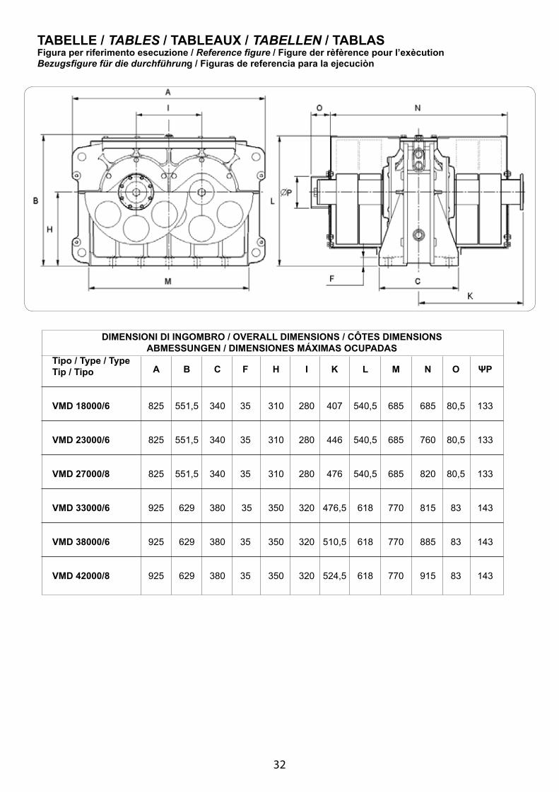
TABELLE / TABLES / TABLEAUX / TABELLEN / TABLASFigura per riferimento esecuzione / Reference figure / Figure der rèfèrence pour l’exècution Bezugsfigure für die durchführung / Figuras de referencia para la ejecuciòn
DIMENSIONI DI INGOMBRO / OVERALL DIMENSIONS / CÔTES DIMENSIONSABMESSUNGEN / DIMENSIONES MÁXIMAS OCUPADAS
Tipo / Type / Type Tip / Tipo A B C F H I K L M N O ΨP
VMD 18000/6 825 551,5 340 35 310 280 407 540,5 685 685 80,5 133 VMD 23000/6 825 551,5 340 35 310 280 446 540,5 685 760 80,5 133 VMD 27000/8 825 551,5 340 35 310 280 476 540,5 685 820 80,5 133 VMD 33000/6 925 629 380 35 350 320 476,5 618 770 815 83 143 VMD 38000/6 925 629 380 35 350 320 510,5 618 770 885 83 143 VMD 42000/8 925 629 380 35 350 320 524,5 618 770 915 83 143

33
Interassi di fissaggio / Fixing distances / Entre-axes de fixation / Abstand der Befestigungsloecher / Intereje de fixaciòn
Tipo / Type / Type Tip / Tipo 4x120 3x110 330 280 180 VMD 18000/6 / / 110 130 130 VMD 23000/6 260 200 220 252 280 VMD 27000/8 26 26 26 32 32 10 x M24 8 x M24 8 x M24 8 x M30 8 x M30
SC FR JS VC TV
DD1E
ØGN°
Tipo / Type / Type Tip / Tipo 5x120 3x140 VMD 33000/6 / / VMD 38000/6 300 250 VMD 42000/8 32 39 12 x M30
SC FR
DD1E
ØGN°
Coppia di serraggio per viti di fissaggio dell’oscillatore meccanico alla strutturaClamping torque for screws fixing the exciter to the structure
Couple de serrage des vis de fixation du excitateur à la structureAnzugsmoment der Schrauben für die Befestigung des Unwucht-Erreger an der Struktur
Par de apriete de los tornillos de fijaciòn de la excitatriz a la estructura N·m ft·lb M24 710 513 M30 1150 830 M36 1900 1370

34
Tipo Masselli aggiuntivi Momento statico Velocità massima Forza centrifuga Cuscinetto Durata cuscinetto Peso (con cop.masse) Type Additional weights Static moment Max speed Centrifugal Force Bearing Bearing lifetime Weight (includ.weight covers) Type Moment statique Vitesse maxim. Force Centrifuge Roulement Tip Statische moment Maxim. Drehzahl Fliekraft Lager Tipo Momento estatico Fuerza Centrifuga Rodamientos Vida rodamientos Peso (con tapas de masa) kgmm RPM kN kg
8225 1435 185,4 46000 563 11525 1239 194,2 46000 584 12245 1207 195,2 46000 606 VMD 18000/6 13580 1151 197,2 22319 47000 620 15545 1075 197,2 50300 628 16645 1039 197,2 52000 635 17980 1000 197,2 54000 649 10410 1410 227,6 46000 631 14600 1217 237,4 46000 658 15510 1186 239,4 46000 686 VMD 23000/6 17260 1132 242,3 46000 704 19700 1069 247,2 46000 713 21135 1037 249,2 46000 723 22885 1000 252,1 46000 741 12065 1115 164,8 89000 629 16940 941 164,8 105000 661 18005 913 164,8 109000 693 VMD 27000/8 20065 864 164,8 115000 715 22875 810 164,8 122000 724 24570 781 164,8 127000 736 26635 750 164,8 132000 758 17650 1220 288,4 40000 895 22663 1095 298,2 40000 922 23762 1072 299,2 40000 950 VMD 33000/6 25853 1034 303,1 40000 969 28775 987 307,1 40000 977 30492 962 310,0 40000 987 32583 935 312,0 40000 1005 20448 1153 298,2 40000 949 26278 1033 308,0 40000 981 27554 1012 310,0 40000 1013 VMD 38000/6 30023 975 312,9 40000 1035 33384 931 317,8 40000 1044 35412 908 319,8 40000 1056 37881 882 322,7 40000 1078
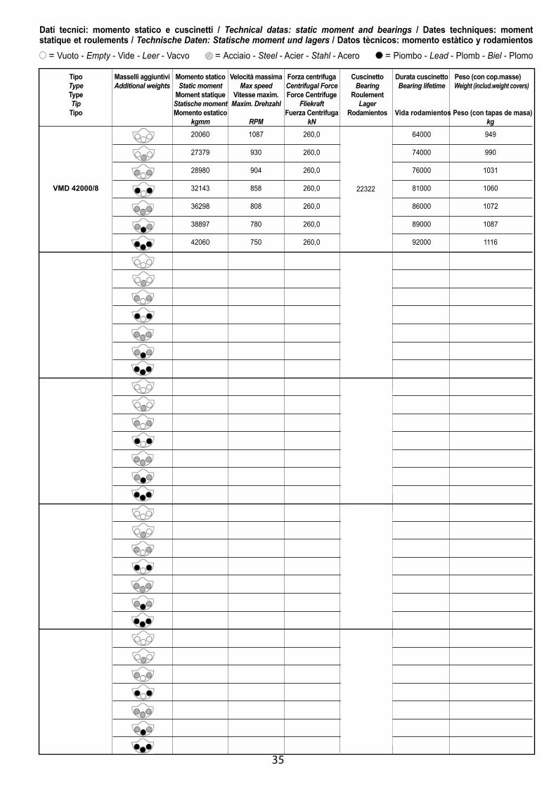
Dati tecnici: momento statico e cuscinetti / Technical datas: static moment and bearings / Dates techniques: moment statique et roulements / Technische Daten: Statische moment und lagers / Datos tècnicos: momento estàtico y rodamientos
= Vuoto - Empty - Vide - Leer - Vacνo = Acciaio - Steel - Acier - Stahl - Acero = Piombo - Lead - Plomb - Biel - Plomo
22319
22320
22319
22322
22324
35
Tipo Masselli aggiuntivi Momento statico Velocità massima Forza centrifuga Cuscinetto Durata cuscinetto Peso (con cop.masse) Type Additional weights Static moment Max speed Centrifugal Force Bearing Bearing lifetime Weight (includ.weight covers) Type Moment statique Vitesse maxim. Force Centrifuge Roulement Tip Statische moment Maxim. Drehzahl Fliekraft Lager Tipo Momento estatico Fuerza Centrifuga Rodamientos Vida rodamientos Peso (con tapas de masa) kgmm RPM kN kg 20060 1087 260,0 64000 949 27379 930 260,0 74000 990 28980 904 260,0 76000 1031 VMD 42000/8 32143 858 260,0 22319 81000 1060 36298 808 260,0 86000 1072 38897 780 260,0 89000 1087 42060 750 260,0 92000 1116
22322
Dati tecnici: momento statico e cuscinetti / Technical datas: static moment and bearings / Dates techniques: moment statique et roulements / Technische Daten: Statische moment und lagers / Datos tècnicos: momento estàtico y rodamientos
= Vuoto - Empty - Vide - Leer - Vacνo = Acciaio - Steel - Acier - Stahl - Acero = Piombo - Lead - Plomb - Biel - Plomo

36
Livello olio / Oil level / Jauge d’huile / Ölstand / Nivel de aceite
Fig. 1
Fig. 2
Fig. 3
Fig. 4
A - Tappo di sfiato / Breather plug with valve / Tapòn des vaporizador B - Asta livello olio / Oil dipstick / Barilla nivel de aceiteC - Tappo scarico olio / Oil drain plug / D - Tappo vetro per livello olio visivo / Glass plug for oil level plug / Tapòn visor nivel de aceite

37
VMD 18000/6 VMD 33000/6 VMD 23000/6 VMD 38000/6 VMD 27000/8 VMD 42000/8 Angolo installaz. Fig. Q.tà olio Q.tà olio Q.tà olio Q.tà olio Q.tà olio Installation angle Fig. Oil q.ty Oil q.ty Oil q.ty Oil q.ty Oil q.ty X Y Q.tè huile X Y Q.tè huile X Y Q.tè huile X Y Q.tè huile X Y Q.tè huile min./max. min./max. min./max. min./max. min./max. ° mm mm l mm mm l mm mm l mm mm l mm mm l 0 335 20 4,9/5,8 392 20 7,4/8,6 +5 315 20 4,5/5,5 371 20 6,6/8,0 +10 301 21 3,5/4,7 355 21 5,4/6,7 +15 287 22 3,0/3,9 340 22 4,3/5,5 +20 273 22 2,7/3,4 325 22 3,9/4,9 +25 260 23 2,6/3,2 310 23 3,7/4,6 +30 246 25 2,5/3,0 295 25 3,6/4,3 +35 232 26 2,5/2,9 280 26 3,5/4,2 +40 217 28 2,4/2,9 264 28 3,5/4,1 +45 201 31 2,4/2,9 247 31 3,4/4,0 +50 483 28 2,4/2,9 548 28 3,4/4,0 +55 499 26 2,4/2,9 566 26 3,4/4,0 +60 514 25 2,5/3,0 584 25 3,4/4,0 +65 529 23 2,5/3,0 600 23 3,4/4,1 +70 543 22 2,5/3,0 617 22 3,4/4,1 +75 557 22 2,5/3,0 633 22 3,4/4,1 +80 572 21 2,5/3,0 650 21 3,4/4,2 +85 587 20 2,5/3,0 667 20 3,4/4,2 +90 602 20 2,5/3,1 685 20 3,4/4,3 180 3 - - 5,3/6,2 - - 8,6/9,8 -5 -10 -15 -20 -25 -30 434 46 2,6/3,2 483 46 4,1/5,0 -35 454 40 2,5/3,1 508 40 3,9/4,7 -40 471 35 2,4/3,0 528 35 3,7/4,5 -45 486 31 2,4/2,9 547 31 3,6/4,3 -50 500 28 2,3/2,9 563 28 3,5/4,2 -55 513 26 2,3/2,9 579 26 3,4/4,1 -60 526 25 2,3/2,9 594 25 3,3/4,1 -65 538 23 2,3/2,9 608 23 3,3/4,1 -70 550 22 2,3/3,0 623 22 3,3/4,2 -75 563 22 2,4/3,0 638 22 3,4/4,3 -80 575 21 2,5/3,1 653 21 3,4/4,4 -85 588 20 2,5/3,1 668 20 3,5/4,4
1
2
4
Tabelle livello olio / Oil level tables / Tableaux de niveau d’huile / Ölstandstabellen / Tablas del nivel de aceite
38
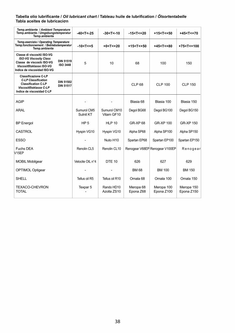
-40<T<-25 -30<T<-10 -15<T<+20 +15<T<+50 +45<T<+70
-10<T<+5 +0<T<+20 +15<T<+50 +45<T<+80 +75<T<+100
5 10 68 100 150
CLP 68 CLP 100 CLP 150 AGIP - - Blasia 68 Blasia 100 Blasia 150
ARAL Sumurol CM5 Sumurol CM10 Degol BG68 Degol BG100 Degol BG150 Sulnit KT Vitam GF10
BP Energol HP 5 HLP 10 GR-XP 68 GR-XP 100 GR-XP 150
CASTROL Hyspin VG10 Hyspin VG10 Alpha SP68 Alpha SP100 Alpha SP150
ESSO - Nuto H10 Spartan EP68 Spartan EP100 Spartan EP150
Fuchs DEA Renolin CL5 Renolin CL10 Renogear V68EP Renogear V100EP R e n o g e a r V15EP MOBIL Mobilgear Velocite OIL n°4 DTE 10 626 627 629
OPTIMOL Optigear - - BM 68 BM 100 BM 150 SHELL Tellus oil R5 Tellus oil R10 Omala 68 Omala 100 Omala 150 TEXACO-CHEVRON Texpar 5 Rando HD10 Meropa 68 Meropa 100 Meropa 150 TOTAL - Azolla ZS10 Epona Z68 Epona Z100 Epona Z150
Temp.ambiente / Ambient TemperatureTemp.ambiante / Umgebungstemperatur
Temp.ambiente
Temp.esercizio / Operating TemperatureTemp.fonctionnement / Betriebstemperatur
Temp.ambiente
Classe di viscositΰ ISO-VG ISO-VG Viscosity Class
Classe de viscositι ISO-VGViscositδtsklasse ISO-VG
Indice de viscosidad ISO-VG
DIN 51519ISO 3448
Classificazione C-LP C-LP Classification Classification C-LP
Viscositδtsklasse C-LPIndice de viscosidad C-LP
DIN 51502DIN 51517
Tabella olio lubrificante / Oil lubricant chart / Tableau huile de lubrification / Ölsortentabelle Tabla aceites de lubricaciσn
39

40
123456789
101112131415161718192021222324252627282930313233343536373839
123456789
101112131415161718192021222324252627282930313233343536373839
123456789
1011121314151617181920212223242526272829303132333435363738
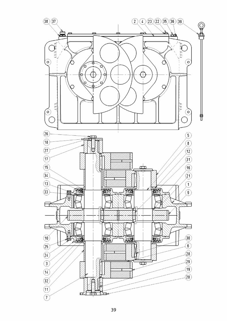
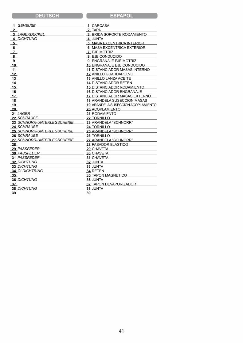
CARCASSE CaSEGEarS COvErBEarinG COvErGEarS COvEr SEaLWEiGhtaDDitiOnaL WEiGhtDrivinG ShaFtDrivEn ShaFtriGht GEarLEFt GEarWEiGht innEr SpaCErDuSt prOtECtivE DiSCOiL thrOWEr DiSCOiL thrOWEr SpaCEr BEarinG SpaCErGEar SpaCErOutSiDE WEiGht SpaCEr WEiGht paCkinG WaShErJOint paCkinG WaShEr JOintBEarinGSCrEWSChnOrr WaShErSCrEWSChnOrr WaShErSCrEWSChnOrr WaShErELaStiC pinkEykEykEySEaL GaSkEtSEaL GaSkEtSEaL rinGMaGnEtiC Drain pLuGSEaL GaSkEtBrEathEr pLuG With vaLvESEaL GaSkEtOiL DipStiCk
ITALIANO ENGLISH FRANΗAIS
CARCASSACOPERCHIO INGRANAGGICOPERCHIO CUSCINETTOGUARNIZ. COPERCHIO INGRANAGGIMASSAMASSELLO AGGIUNTIVOALBERO CONDUTTOREALBERO CONDOTTOINGRANAGGIO DX.INGRANAGGIO SX.DISTANZIALE MASSE INTERNODISCO PARAPOLVEREDISCO LANCIAOLIODISTANZIALE LANCIAOLIODISTANZIALE CUSCINETTODISTANZIALE INGRANAGGIODISTANZIALE MASSE ESTERNORONDELLA RITEGNO MASSERONDELLA RITEGNO GIUNTOGIUNTOCUSCINETTO ORIENTABILE A RULLIVITERONDELLA SCHNORRVITERONDELLA SCHNORRVITERONDELLA SCHNORRSPINA ELASTICALINGUETTA LINGUETTALINGUETTAGUARNIZIONEGUARNIZIONEANELLO DI TENUTATAPPO MAGNETICOGUARNIZIONE TAPPO DI SFIATOGUARNIZIONEASTA LIVELLO OLIO
41
123456789
101112131415161718192021222324252627282930313233343536373839
123456789
101112131415161718192021222324252627282930313233343536373839
CARCASATAPABRIDA SOPORTE RODAMIENTOJUNTA MASA EXCENTRICA INTERIORMASA EXCENTRICA EXTERIOR EJE MOTRIZEJE CONDUCIDOENGRANAJE EJE MOTRIZENGRANAJE EJE CONDUCIDODISTANCIADOR MASAS INTERNOANILLO GUARDAPOLVOANILLO LANZA ACEITEDISTANCIADOR RETENDISTANCIADOR RODAMIENTODISTANCIADOR ENGRANAJEDISTANCIADOR MASAS EXTERNOARANDELA SUSECCION MASASARANDELA SUSECCION ACOPLAMIENTO ACOPLAMIENTORODAMIENTOTORNILLOARANDELA “SCHNORR”TORNILLOARANDELA “SCHNORR”TORNILLOARANDELA “SCHNORR”PASADOR ELASTICOCHAVETACHAVETACHAVETAJUNTAJUNTARETENTAPON MAGNETICOJUNTATAPON DEVAPORIZADORJUNTA
DEUTSCH ESPAΡOL
Gehεuse
LaGErDECkELDiChtunG
LaGErSChrauBESChnOrr-untErLEGSChEiBESChrauBESChnOrr-untErLEGSChEiBESChrauBESChnOrr-untErLEGSChEiBE
paSSFEDErpaSSFEDErpaSSFEDErDiChtunGDiChtunGÖLDiChtrinG
DiChtunG
DiChtunG

42
Flangia di accoppiamento / Coupling flange / Bride de couplage / / Acoplamiento de interconexiσn
Potenza elettrica motore di azionamentoDrive motor electrical rated power
Puissance electrique du moteur d’actionnement
Potencia elιctrica del motor de tracciσn kW VMD 18000/6 11 VMD 23000/6 15 VMD 27000/8 11 VMD 33000/6 18,5 VMD 38000/6 18,5 VMD 42000/8 18,5
130 ± 0.1 VMD 18000/6 12 B12 VMD 23000/6 90 h6 VMD 27000/8 150 2.3
ddfdidet
155.5 ± 0.1 VMD 33000/6 M16 VMD 38000/6 110 h6 VMD 42000/8 180
ddfdidet
mm
mm

43
Accoppiamento di oscillatori / Exciters coupling / Couplage des excitateurs /
44
DICHIARAZIONE DI INCORPORAZIONE (Allegato II.B Direttiva 2006/42/CE)DECLARATION OF INCORPORATION (Annex II.B Directive 2006/42/EC)
DECLARATION D’INCORPORATIONEINBAUERKLÄRUNG
DECLARACION DE INCORPORACION
Il costruttore / The manufacturer / Le constructeur / Der Hersteller / El constructor:
Venanzetti Vibrazioni Milano Srl
Via De Gasperi, 14 - 42019 Scandiano (RE) Italia - Tel.+39-0522-851279 - Fax +39-0522-765357Sede legale: Via dell’Annunciata, 21 - Milano
DICHIARA che: / DECLARES that: / DECLARE que: / ERKLÄRT, DASS: / DECLARA que:
gli oscillatori meccanici della serie: / the linear motion exciters of the series:/ les excitateurs à balourds de les séries: die Unwucht-Erreger der Serien: / les excitadores desequilibrados de las series:
VMD
devono essere installati secondo le istruzioni fornite dal costruttore e non devono essere messi in servizio fino a che le macchine nelle quali verranno incorporati non siano state dichiarate conformi, se del caso, alla Direttiva Macchine 2006/42/CE must be installed following manufacturer instructions and must not be put into service until the final machineries into which they are to be incorporated have been declared in conformity with the provisions of the Machinery Directive 2006/ 42/EC, where appropriate
hanno documentazione tecnica pertinente compilata in conformità dell’allegato VII B have the relevant technical documentation is compiled in accordance with part B of Annex VII
e sono caratterizzati da informazioni tecniche che il costruttore si impegna a trasmettere alle competenti autorità nazionali in caso di richiesta adeguatamente motivata and they are characterized by relevant informations that the manufacturer undertakes to transmit to the national authorities in response to a reasoned request
Fiorano 01 Gennaio 2010
_________________________________ Presidente e persona autorizzata Firma / Signature / Signature / Unterschrift / Firma President and person authorised President Präsident Presidente
45
Venanzetti Vibrazioni Milano SrlVia De Gasperi, 14 - 42019 Scandiano (RE) Italia
Tel.+39-0522-851279 - Fax +39-0522-765357Sede legale: Via dell’Annunciata, 21 - Milano