veka - old.salda.ltold.salda.lt/content/download/veka en_lt_ru_pl.pdfaccessories 156 the company...
TRANSCRIPT

Accessories
The company reserves the right to make changes of technical data without prior notice156
• Low noise level. • Adjustable voltage fan control. • Electrical or water heater. • Easily removable inspection cover. • Filter box with pocket filter M5 class. • Possibility to install under the ceiling. • Optional wide range controls available. Air supply units for ventilation systems. Units’ casing is made of
galvanized steel and have insulation of 50 mm. Consists of cen-trifugal fan, heater (electrical or water), pocket filter. Not designed for functioning in explosive – inclined areas. Units are designed for clean air supply into premises. Have additional mounting brackets for under the ceiling instalation.
VEKA
AIR
HA
ND
LIN
G U
NIT
S
TGRV
Single phase speed controller
EKR 15.1PEKR 15.1 EKR 6.1 ETY/MTY
Monophase speed controller
Controller for electrical heater
Controller for electrical heater
TGRT
Three phase speed controller Shuft-off damper
SKG
Back draft shutter
RSK
Circular ducts silencer
AKS p. 230 p. 226 p. 221 p. 222 p. 227 p. 225 p. 224 p. 223
• Niski poziom hałasu.• Regulacja wentylatora napięcia.• Elektryczne lub podgrzewacz wody.• Łatwo zdejmowana pokrywa inspekcji.• Filtr pudełko z kieszeni M5 klasy filtra.• Możliwość instalacji pod sufitem.• Opcjonalnie dostępna szeroka gama kontroluje.Jednostki nawiewne dla systemów wentylacyjnych. Obudowa
Jednostki “wykonana jest z ocynkowanej stali i ma izolację 50 mm. Składa się z odśrodkowa wentylator, ogrzewanie (elektryczne lub wody), kieszeń na filtr. nie przeznaczone do funkcjonowania w wybuchowy - pochyłych obszarach. Urządzenia są przeznaczone do czyste powietrze do pomieszczeń. Mają dodatkowe uchwyty montażowe do montażu pod sufitem.
• Mažas triukšmo lygis.• Reguliuojamo greičio ventiliatorius (įtampos keitimas).• Elektrinis arba vandeninis šildytuvas.• Lengvai nuimamas dangtis patikrinimui.• Filtrų dėžė su M5 klasės filtru.Oro tiekimo agregatas skirtas oro padavimui į patalpas. Jis susi-
deda iš išcentrinio ventiliatoriaus, kurio greitis gali būti valdomas reguliatoriumi, oro šildytuvo ir kišeninio filtro. Visi šie elementai sumontuoti izoliuotame korpuse. Izoliacijos storis 50 mm. Korpu-sas pagamintas iš cinkuotos skardos su lengvai nuimamu dangčiu. Dangtis tvirtinamas keturiais lengvai atsegamais lankstais.
• Низкий уровень шума.• Вентилятор с регулированием скорости (изменение
напряжения).• Электрический или водяной нагреватель.• Легко снимаемая крышка для проверки.• Кассета фильтров с фильтром класса M5.• Дополнительно широкий спектр по подбору автоматики.Агрегат подачи воздуха предназначен для подачи воздуха
в помещения. Он состоит из эксцентрического вентилятора, скорость которого изменяется регулятором, а также нагревателя воздуха и карманного фильтра. Все эти элементы установлены в изолированном корпусе. Толщина изоляции 50 мм. Корпус изготовлен из оцинкованной жести с легко снимаемой крышкой. Крышка крепится легко отстёгивающимися шарнирами.
Air handling units
Oro tiekimo agrgatai
Centrale klimatyzacyjne
Приточные агрегаты
Accessories
157The company reserves the right to make changes of technical data without prior notice
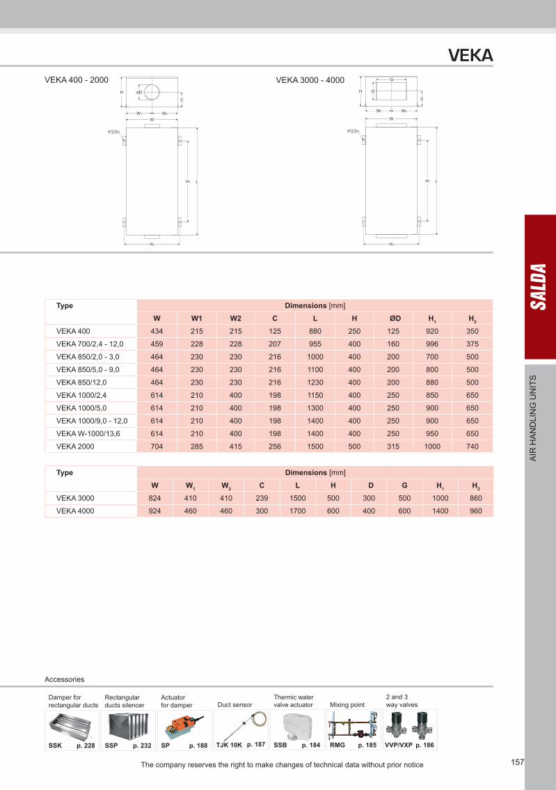
VEKA 400 - 2000 VEKA 3000 - 4000
Type Dimensions [mm]
W W1 W2 C L H ØD H1 H2
VEKA 400 434 215 215 125 880 250 125 920 350
VEKA 700/2,4 - 12,0 459 228 228 207 955 400 160 996 375
VEKA 850/2,0 - 3,0 464 230 230 216 1000 400 200 700 500
VEKA 850/5,0 - 9,0 464 230 230 216 1100 400 200 800 500
VEKA 850/12,0 464 230 230 216 1230 400 200 880 500
VEKA 1000/2,4 614 210 400 198 1150 400 250 850 650
VEKA 1000/5,0 614 210 400 198 1300 400 250 900 650
VEKA 1000/9,0 - 12,0 614 210 400 198 1400 400 250 900 650
VEKA W-1000/13,6 614 210 400 198 1400 400 250 950 650
VEKA 2000 704 285 415 256 1500 500 315 1000 740
Type Dimensions [mm]
W W1 W2 C L H D G H1 H2
VEKA 3000 824 410 410 239 1500 500 300 500 1000 860
VEKA 4000 924 460 460 300 1700 600 400 600 1400 960
VEKA
AIR
HA
ND
LIN
G U
NIT
S
SSK
Damper for rectangular ducts
SSP
Rectangular ducts silencer Duct sensor
Actuator for damper
SP TJK 10K p. 228 p. 232 p. 188 p. 187 SSB p. 184
Thermic watervalve actuator Mixing point
2 and 3 way valves
RMG VVP/VXP p. 185 p. 186

The company reserves the right to make changes of technical data without prior notice158
VEKA
AIR
HA
ND
LIN
G U
NIT
S
Type Accessories
TGRV TGRT ETYMTY
EKR 15.1EKR 15.1P
EKR 6.1
RSKSKGAKSAP
SSKSSP
SPPS
TJK10K
SSBHeating
SSBCooling
RMG 80/600C
RMG 60/400C
VVP/VXP 80/600C
VVP/VXP 60/400C
VEKA 400/1,2-L1 1,5 - 1,5 - + 125 - + + - - - - - -
VEKA 400/2,0-L1 1,5 - 1,5 - + 125 - + + - - - - - -
VEKA 400/5,0-L1 1,5 - 1,5 - + 125 - + + - - - - - -
VEKA 700/2,4-L1 1,5 - 1,5 - + 160 - + + - - - - - -
VEKA 700/5,0-L1 1,5 - 1,5 - + 160 - + + - - - - - -
VEKA 700/9,0-L1 1,5 - 1,5 15.1 - 160 - + + - - - - - -
VEKA 700/12,0-L1 1,5 - 1,5 15.1 - 160 - + + - - - - - -
VEKA 850/2,0-L1 2 - 1,5 - + 200 - + + - - - - - -
VEKA 850/3,0-L1 2 - 1,5 - + 200 - + + - - - - - -
VEKA 850/5,0-L1 2 - 1,5 - + 200 - + + - - - - - -
VEKA 850/6,0-L1 2 - 1,5 - + 200 - + + - - - - - -
VEKA 850/9,0-L1 2 - 1,5 15.1 - 200 - + + - - - - - -
VEKA 850/12,0-L1 2 - 1,5 15.1 - 200 - + + - - - - - -
VEKA1000/2,4-L1 5 - 4 - + 250 - + + - - - - - -
VEKA1000/2,4-L3 - 3 - - + 250 - + + - - - - - -
VEKA1000/5,0-L1 5 - 4 - + 250 - + + - - - - - -
VEKA1000/5,0-L3 - 3 - - + 250 - + + - - - - - -
VEKA1000/9,0-L1 5 - 4 15.1 - 250 - + + - - - - - -
VEKA1000/9,0-L3 - 3 - 15.1 - 250 - + + - - - - - -
VEKA1000/12,0-L1 5 - 4 15.1 - 250 - + + - - - - - -
VEKA1000/12,0-L3 - 3 - 15.1 - 250 - + + - - - - - -
VEKA W-1000/13,6-L1 5 - 4 - - 250 - + - 61* 81* 3-1,6-4 3-1,0-4 45.10-1,6 45.10-1,0
VEKA W-1000/13,6-L3 - 3 - - - 250 - + - 61* 81* 3-1,6-4 3-1,0-4 45.10-1,6 45.10-1,0
VEKA 2000/6,0-L1 11 - - - + 315 - + + - - - - - -
VEKA 2000/6,0-L3 - 4 - - + 315 - + + - - - - - -
VEKA 2000/15,0-L1 11 - - 15.1 - 315 - + + - - - - - -
VEKA 2000/15,0-L3 - 4 - 15.1 - 315 - + + - - - - - -
VEKA 2000/21,0-L1 11 - - 15.1P - 315 - + + - - - - - -
VEKA 2000/21,0-L3 - 4 - 15.1P - 315 - + + - - - - - -
VEKA W-2000/27,2-L1 11 - - - - 315 - + - 61* 81* 3-2,5-4 3-1,6-4 45.15-2,5 45.10-1,6
VEKA W-2000/27,2-L3 - 4 - - - 315 - + - 61* 81* 3-2,5-4 3-1,6-4 45.15-2,5 45.10-1,6
VEKA 3000/15,0-L1 14 - - 15.1 - - 500x300 + + - - - - - -
VEKA 3000/15,0-L3 - 7 - 15.1 - - 500x300 + + - - - - - -
VEKA 3000/21,0-L1 14 - - 15.1P - - 500x300 + + - - - - - -
VEKA 3000/21,0-L3 - 7 - 15.1P - - 500x300 + + - - - - - -
VEKA 3000/30,0-L1 14 - - 15.1P - - 500x300 + + - - - - - -
VEKA 3000/30,0-L3 - 7 - 15.1P - - 500x300 + + - - - - - -
VEKA 3000/39,0-L1 14 - - 15.1P - - 500x300 + + - - - - - -
VEKA 3000/39,0-L3 - 7 - 15.1P - - 500x300 + + - - - - - -
VEKA W-3000/40,8-L1 14 - - 15.1P - - 500x300 + - 61* 81* 3-4,0-4 3-2,5-4 45.20-4,0 45.15-2,5
VEKA W-3000/40,8-L3 - 7 - 15.1P - - 500x300 + - 61* 81* 3-4,0-4 3-2,5-4 45.20-4,0 45.15-2,5
VEKA 4000/21,0-L3 - 11 - 15.1P - - 600x400 + + - - - - - -
VEKA 4000/27,0-L3 - 11 - 15.1P - - 600x400 + + - - - - - -
VEKA 4000/39,0-L3 - 11 - 15.1P - - 600x400 + + - - - - - -
VEKA4000/54,0-L3 - 11 - 15.1P - - 600x400 + + - - - - - -
VEKA W-4000/54,0-L3 - 11 - - - - 600x400 + + 61* 81* 3-6,3-4 3-4,0-4 45.25-6,3 45.20-4,0
* - only with PRV control board
159The company reserves the right to make changes of technical data without prior notice
Air flow [m3/h]
Sta
tic p
ress
ure
[Pa]
Air flow [m3/h]
Sta
tic p
ress
ure
[Pa]
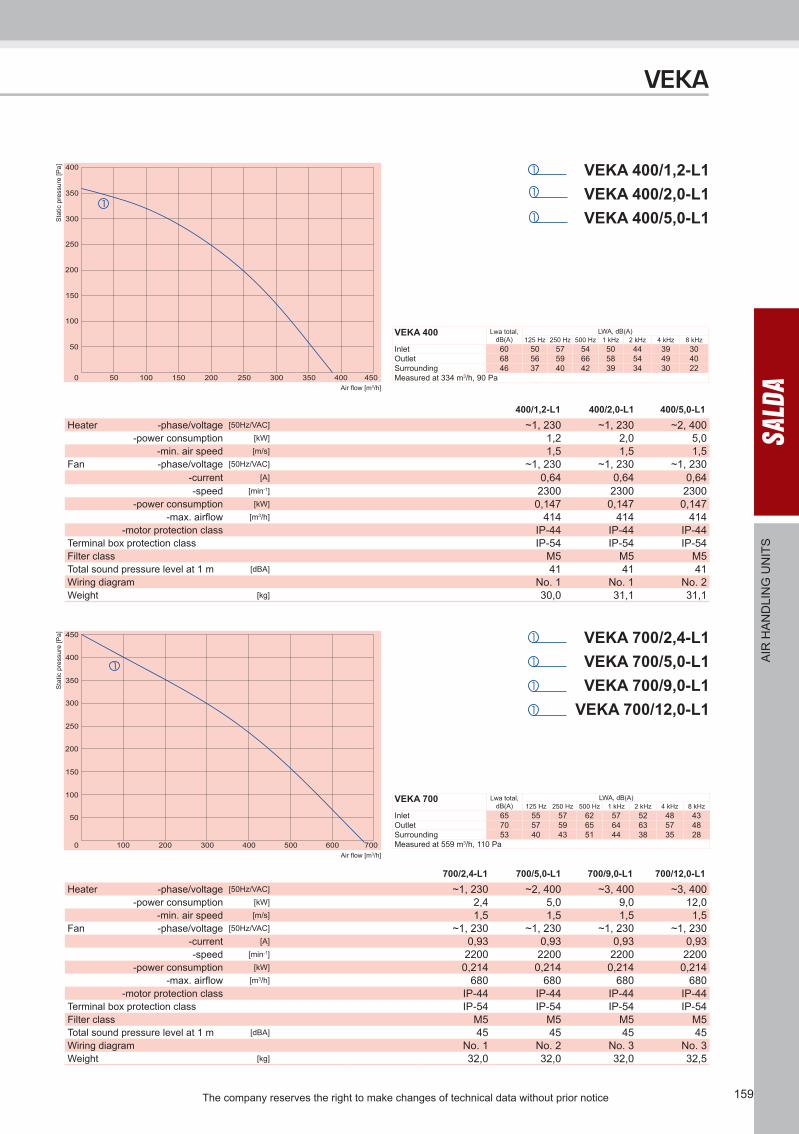
400/1,2-L1 400/2,0-L1 400/5,0-L1
VEKA 400/1,2-L1VEKA 400/2,0-L1VEKA 400/5,0-L1
700/2,4-L1 700/5,0-L1 700/9,0-L1 700/12,0-L1
VEKA 700/2,4-L1VEKA 700/5,0-L1VEKA 700/9,0-L1
VEKA 700/12,0-L1
Heater -phase/voltage [50Hz/VAC] ~1, 230 ~1, 230 ~2, 400-power consumption [kW] 1,2 2,0 5,0
-min. air speed [m/s] 1,5 1,5 1,5Fan -phase/voltage [50Hz/VAC] ~1, 230 ~1, 230 ~1, 230
-current [A] 0,64 0,64 0,64-speed [min-1] 2300 2300 2300
-power consumption [kW] 0,147 0,147 0,147-max. airflow [m3/h] 414 414 414
-motor protection class IP-44 IP-44 IP-44Terminal box protection class IP-54 IP-54 IP-54Filter class M5 M5 M5Total sound pressure level at 1 m [dBA] 41 41 41Wiring diagram No. 1 No. 1 No. 2Weight [kg] 30,0 31,1 31,1
Heater -phase/voltage [50Hz/VAC] ~1, 230 ~2, 400 ~3, 400 ~3, 400-power consumption [kW] 2,4 5,0 9,0 12,0
-min. air speed [m/s] 1,5 1,5 1,5 1,5Fan -phase/voltage [50Hz/VAC] ~1, 230 ~1, 230 ~1, 230 ~1, 230
-current [A] 0,93 0,93 0,93 0,93-speed [min-1] 2200 2200 2200 2200
-power consumption [kW] 0,214 0,214 0,214 0,214-max. airflow [m3/h] 680 680 680 680
-motor protection class IP-44 IP-44 IP-44 IP-44Terminal box protection class IP-54 IP-54 IP-54 IP-54Filter class M5 M5 M5 M5Total sound pressure level at 1 m [dBA] 45 45 45 45Wiring diagram No. 1 No. 2 No. 3 No. 3Weight [kg] 32,0 32,0 32,0 32,5
VEKA
AIR
HA
ND
LIN
G U
NIT
S
VEKA 400 Lwa total, dB(A)
LWA, dB(A)125 Hz 250 Hz 500 Hz 1 kHz 2 kHz 4 kHz 8 kHz
Inlet 60 50 57 54 50 44 39 30Outlet 68 56 59 66 58 54 49 40Surrounding 46 37 40 42 39 34 30 22Measured at 334 m3/h, 90 Pa
VEKA 700 Lwa total, dB(A)
LWA, dB(A)125 Hz 250 Hz 500 Hz 1 kHz 2 kHz 4 kHz 8 kHz
Inlet 65 55 57 62 57 52 48 43Outlet 70 57 59 65 64 63 57 48Surrounding 53 40 43 51 44 38 35 28Measured at 559 m3/h, 110 Pa
The company reserves the right to make changes of technical data without prior notice160
Air flow [m3/h]
Sta
tic p
ress
ure
[Pa]
Air flow [m3/h]
Sta
tic p
ress
ure
[Pa]
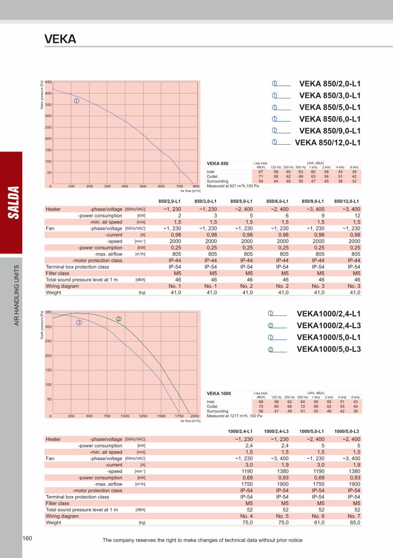
850/2,0-L1 850/3,0-L1 850/5,0-L1 850/6,0-L1 850/9,0-L1 850/12,0-L1
VEKA1000/2,4-L1VEKA1000/2,4-L3VEKA1000/5,0-L1VEKA1000/5,0-L3
1000/2,4-L1 1000/2,4-L3 1000/5,0-L1 1000/5,0-L3
VEKA 850/2,0-L1VEKA 850/3,0-L1VEKA 850/5,0-L1VEKA 850/6,0-L1VEKA 850/9,0-L1
VEKA 850/12,0-L1
Heater -phase/voltage [50Hz/VAC] ~1, 230 ~1, 230 ~2, 400 ~2, 400 ~3, 400 ~3, 400-power consumption [kW] 2 3 5 6 9 12
-min. air speed [m/s] 1,5 1,5 1,5 1,5 1,5 1,5Fan -phase/voltage [50Hz/VAC] ~1, 230 ~1, 230 ~1, 230 ~1, 230 ~1, 230 ~1, 230
-current [A] 0,98 0,98 0,98 0,98 0,98 0,98-speed [min-1] 2000 2000 2000 2000 2000 2000
-power consumption [kW] 0,25 0,25 0,25 0,25 0,25 0,25-max. airflow [m3/h] 805 805 805 805 805 805
-motor protection class IP-44 IP-44 IP-44 IP-44 IP-44 IP-44Terminal box protection class IP-54 IP-54 IP-54 IP-54 IP-54 IP-54Filter class M5 M5 M5 M5 M5 M5Total sound pressure level at 1 m [dBA] 46 46 46 46 46 46Wiring diagram No. 1 No. 1 No. 2 No. 2 No. 3 No. 3Weight [kg] 41,0 41,0 41,0 41,0 41,0 41,0
Heater -phase/voltage [50Hz/VAC] ~1, 230 ~1, 230 ~2, 400 ~2, 400-power consumption [kW] 2,4 2,4 5 5
-min. air speed [m/s] 1,5 1,5 1,5 1,5Fan -phase/voltage [50Hz/VAC] ~1, 230 ~3, 400 ~1, 230 ~3, 400
-current [A] 3,0 1,9 3,0 1,9-speed [min-1] 1190 1380 1190 1380
-power consumption [kW] 0,69 0,93 0,69 0,93-max. airflow [m3/h] 1750 1900 1750 1900
-motor protection class IP-54 IP-54 IP-54 IP-54Terminal box protection class IP-54 IP-54 IP-54 IP-54Filter class M5 M5 M5 M5Total sound pressure level at 1 m [dBA] 52 52 52 52Wiring diagram No. 4 No. 5 No. 6 No. 7Weight [kg] 75,0 75,0 61,0 65,0
VEKA
AIR
HA
ND
LIN
G U
NIT
S
VEKA 850 Lwa total, dB(A)
LWA, dB(A)125 Hz 250 Hz 500 Hz 1 kHz 2 kHz 4 kHz 8 kHz
Inlet 67 56 60 63 60 58 45 39Outlet 71 58 62 69 63 56 51 42Surrounding 54 44 48 50 47 45 38 32Measured at 627 m3/h,100 Pa
VEKA 1000 Lwa total, dB(A)
LWA, dB(A)125 Hz 250 Hz 500 Hz 1 kHz 2 kHz 4 kHz 8 kHz
Inlet 68 58 62 64 59 55 51 43Outlet 75 60 68 72 69 62 55 49Surrounding 56 47 49 51 50 48 42 39Measured at 1217 m3/h, 100 Pa

161The company reserves the right to make changes of technical data without prior notice
Air flow [m3/h]
Sta
tic p
ress
ure
[Pa]
Air flow [m3/h]
Sta
tic p
ress
ure
[Pa]
VEKA1000/9,0-L1VEKA1000/9,0-L3
VEKA1000/12,0-L1VEKA1000/12,0-L3
1000/9,0-L1 1000/9,0-L3 1000/12,0-L1 1000/12,0-L3
VEKA W-1000/13,6-L1VEKA W-1000/13,6-L3
W-1000/13,6-L1 W-1000/13,6-L3
Heater -phase/voltage [50Hz/VAC] ~3, 400 ~3, 400 ~3, 400 ~3, 400-power consumption [kW] 9 9 12 12
-min. air speed [m/s] 1,5 1,5 1,5 1,5Fan -phase/voltage [50Hz/VAC] ~1, 230 ~3, 400 ~1, 230 ~3, 400
-current [A] 3,0 1,9 3,0 1,9-speed [min-1] 1190 1380 1190 1380
-power consumption [kW] 0,69 0,93 0,69 0,93-max. airflow [m3/h] 1750 1900 1750 1900
-motor protection class IP-54 IP-54 IP-54 IP-54Terminal box protection class IP-54 IP-54 IP-54 IP-54Filter class M5 M5 M5 M5Total sound pressure level at 1 m [dBA] 52 52 52 52Wiring diagram No. 8 No. 9 No. 12 No. 13Weight [kg] 70,0 70,0 73,0 73,0
Water heater -power [kW] 13,6 13,6-water temp. Tin/Tout
[oC] +80/+60 +80/+60-water flow rate [l/s] 0,17 0,17
-water pressure drop [kPa] 13,81 13,81-kvs value [m³/h] 1,5 1,5
Fan -phase/voltage [50Hz/VAC] ~1, 230 ~3, 400-current [A] 3,0 1,9-speed [min-1] 1190 1380
-power consumption [kW] 0,69 0,93-max. airflow [m3/h] 1540 1620
-motor protection class IP-54 IP-54Terminal box protection class IP-54 IP-54Filter class M5 M5Total sound pressure level at 1 m [dBA] 52 52Wiring diagram No. 14 No. 15Weight [kg] 78,0 78,0
VEKA
AIR
HA
ND
LIN
G U
NIT
S
VEKA W 1000 Lwa total, dB(A)
LWA, dB(A)125 Hz 250 Hz 500 Hz 1 kHz 2 kHz 4 kHz 8 kHz
Inlet 68 59 61 63 60 57 50 41Outlet 75 61 67 71 69 64 53 46Surrounding 55 46 48 50 49 45 40 37Measured at 1185 m3/h, 100 Pa
VEKA 1000 Lwa total, dB(A)
LWA, dB(A)125 Hz 250 Hz 500 Hz 1 kHz 2 kHz 4 kHz 8 kHz
Inlet 68 58 62 64 59 55 51 43Outlet 75 60 68 72 69 62 55 49Surrounding 56 47 49 51 50 48 42 39Measured at 1217 m3/h, 100 Pa
The company reserves the right to make changes of technical data without prior notice162
Air flow [m3/h]
Sta
tic p
ress
ure
[Pa]
Air flow [m3/h]
Sta
tic p
ress
ure
[Pa]
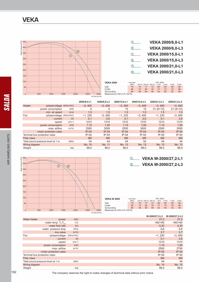
VEKA 2000/6,0-L1VEKA 2000/6,0-L3
VEKA 2000/15,0-L1VEKA 2000/15,0-L3VEKA 2000/21,0-L1VEKA 2000/21,0-L3
2000/6,0-L1 2000/6,0-L3 2000/15,0-L1 2000/15,0-L3 2000/21,0-L1 2000/21,0-L3
VEKA W-2000/27,2-L1VEKA W-2000/27,2-L3
W-2000/27,2-L1 W-2000/27,2-L3
Heater -phase/voltage [50Hz/VAC] ~2, 400 ~2, 400 ~3, 400 ~3, 400 ~3, 400 ~3, 400-power consumption [kW] 6 6 15 15 21 (9+12) 21 (9+12)
-min. air speed [m/s] 1,5 1,5 1,5 1,5 1,5 1,5Fan -phase/voltage [50Hz/VAC] ~1, 230 ~3, 400 ~1, 230 ~3, 400 ~1, 230 ~3, 400
-current [A] 5,1 2,6 5,1 2,6 5,1 2,6-speed [min-1] 1210 1310 1210 1310 1210 1310
-power consumption [kW] 1,15 1,50 1,15 1,50 1,15 1,50-max. airflow [m3/h] 2500 3000 2500 3000 2500 3000
-motor protection class IP-54 IP-54 IP-54 IP-54 IP-54 IP-54Terminal box protection class IP-54 IP-54 IP-54 IP-54 IP-54 IP-54Filter class M5 M5 M5 M5 M5 M5Total sound pressure level at 1 m [dBA] 54 54 54 54 54 54Wiring diagram No. 10 No. 11 No. 12 No. 13 No. 12 No. 13Weight [kg] 98,0 98,0 98,0 98,0 98,0 98,0
Water heater -power [kW] 27,2 27,2-water temp. Tin/Tout
[oC] +80/+60 +80/+60-water flow rate [l/s] 0,32 0,32
-water pressure drop [kPa] 9,6 9,6-kvs value [m³/h] 3,7 3,7
Fan -phase/voltage [50Hz/VAC] ~1, 230 ~3, 400-current [A] 5,1 2,6-speed [min-1] 1210 1310
-power consumption [kW] 1,15 1,50-max. airflow [m3/h] 2500 2790
-motor protection class IP-54 IP-54Terminal box protection class IP-54 IP-54Filter class M5 M5Total sound pressure level at 1 m [dBA] 54 54Wiring diagram No. 14 No. 15Weight [kg] 98,0 98,0
VEKA
AIR
HA
ND
LIN
G U
NIT
S
VEKA 2000 Lwa total, dB(A)
LWA, dB(A)125 Hz 250 Hz 500 Hz 1 kHz 2 kHz 4 kHz 8 kHz
Inlet 79 70 77 72 65 62 60 56Outlet 85 73 80 79 77 73 72 68Surrounding 66 58 64 58 52 50 52 49Measured at 2102 m3/h,130 Pa
VEKA W 2000 Lwa total, dB(A)
LWA, dB(A)125 Hz 250 Hz 500 Hz 1 kHz 2 kHz 4 kHz 8 kHz
Inlet 79 70 77 72 65 62 60 56Outlet 85 73 80 79 77 73 72 68Surrounding 66 58 64 58 52 50 52 49Measured at 2102 m3/h,130 Pa

163The company reserves the right to make changes of technical data without prior notice
Air flow [m3/h]
Sta
tic p
ress
ure
[Pa]
Air flow [m3/h]
Sta
tic p
ress
ure
[Pa]
VEKA
AIR
HA
ND
LIN
G U
NIT
S
VEKA 3000/15,0-L1VEKA 3000/15,0-L3VEKA 3000/21,0-L1VEKA 3000/21,0-L3
3000/15,0-L1 3000/15,0-L3 3000/21,0-L1 3000/21,0-L3
VEKA 3000/30,0-L1VEKA 3000/30,0-L3VEKA 3000/39,0-L1VEKA 3000/39,0-L3
3000/30,0-L1 3000/30,0-L3 3000/39,0-L1 3000/39,0-L3
Heater -phase/voltage [50Hz/VAC] ~3, 400 ~3, 400 ~3, 400 ~3, 400-power consumption [kW] 15 15 21 (9+12) 21 (9+12)
-min. air speed [m/s] 1,5 1,5 1,5 1,5Fan -phase/voltage [50Hz/VAC] ~1, 230 ~3, 400 ~1, 230 ~3, 400
-current [A] 11,0 4,1 11,0 4,1-speed [min-1] 1340 1300 1340 1300
-power consumption [kW] 2,5 2,5 2,5 2,5-max. airflow [m3/h] 4000 4500 4000 4500
-motor protection class IP 54 IP 54 IP 54 IP 54Terminal box protection class IP 54 IP 54 IP 54 IP 54Filter class M5 M5 M5 M5Total sound pressure level at 1 m [dBA] 56 56 56 56Wiring diagram No. 12 No. 13 No. 12 No. 13Weight [kg] 103,0 103,0 103,0 103,0
Heater -phase/voltage [50Hz/VAC] ~3, 400 ~3, 400 ~3, 400 ~3, 400-power consumption [kW] 30 (15+15) 30 (15+15) 39 (9+12+18) 39 (9+12+18)
-min. air speed [m/s] 1,5 1,5 1,5 1,5Fan -phase/voltage [50Hz/VAC] ~1, 230 ~3, 400 ~1, 230 ~3, 400
-current [A] 11,0 4,1 11,0 4,1-speed [min-1] 1340 1300 1340 1300
-power consumption [kW] 2,5 2,5 2,5 2,5-max. airflow [m3/h] 4000 4500 4000 4500
-motor protection class IP 54 IP 54 IP 54 IP 54Terminal box protection class IP 54 IP 54 IP 54 IP 54Filter class M5 M5 M5 M5Total sound pressure level at 1 m [dBA] 56 56 56 56Wiring diagram No. 12 No. 13 No. 12 No. 13103,0Weight [kg] 103,0 103,0 103,0 103,0
VEKA 3000 Lwa total, dB(A)
LWA, dB(A)125 Hz 250 Hz 500 Hz 1 kHz 2 kHz 4 kHz 8 kHz
Inlet 80 71 70 76 75 68 62 58Outlet 86 73 76 82 80 76 72 65Surrounding 67 60 63 59 56 53 49 46Measured at 3480 m3/h, 100 Pa
VEKA 3000 Lwa total, dB(A)
LWA, dB(A)125 Hz 250 Hz 500 Hz 1 kHz 2 kHz 4 kHz 8 kHz
Inlet 80 71 70 76 75 68 62 58Outlet 86 73 76 82 80 76 72 65Surrounding 67 60 63 59 56 53 49 46Measured at 3480 m3/h, 100 Pa

The company reserves the right to make changes of technical data without prior notice164
Air flow [m3/h]
Sta
tic p
ress
ure
[Pa]
Air flow [m3/h]
Sta
tic p
ress
ure
[Pa]
VEKA W-3000/40,8-L1VEKA W-3000/40,8-L3
VEKA 4000/21,0-L3VEKA 4000/27,0-L3VEKA 4000/39,0-L3VEKA4000/54,0-L3
4000/21,0-L3 4000/27,0-L3 4000/39,0-L3 4000/54,0-L3Heater -phase/voltage [50Hz/VAC] ~3, 400 ~3, 400 ~3, 400 ~3, 400
-power consumption [kW] 21 (9+12) 27 (12+15) 39 (9+12+18) 54 (9+12+15+18)-min. air speed [m/s] 1,5 1,5 1,5 1,5
Fan -phase/voltage [50Hz/VAC] ~3, 400 ~3, 400 ~3, 400 ~3, 400-current [A] 6,0 6,0 6,0 6,0-speed [min-1] 1320 1320 1320 1320
-power consumption [kW] 3,7 3,7 3,7 3,7-max. airflow [m3/h] 6020 6020 6020 6020
-motor protection class IP 54 IP 54 IP 54 IP 54Terminal box protection class IP 54 IP 54 IP 54 IP 54Filter class M5 M5 M5 M5Total sound pressure level at 1 m [dBA] 58 58 58 58Wiring diagram No. 13 No. 13 No. 13 No. 13Weight [kg] 175,0 175,0 175,0 175,0
Water heater -power [kW] 40,8 40,8-water temp. Tin/Tout
[oC] +80/+60 +80/+60-water flow rate [l/s] 0,49 0,49
-water pressure drop [kPa] 5,7 5,7-kvs value [m³/h] 7,4 7,4
Fan -phase/voltage [50Hz/VAC] ~1, 230 ~3, 400-current [A] 11 4,10-speed [min-1] 1340 1300
-power consumption [kW] 2,5 2,5-max. airflow [m3/h] 3770 3740
-motor protection class IP 54 IP 54Terminal box protection class IP 54 IP 54Filter class M5 M5Total sound pressure level at 1 m [dBA] 56 56Wiring diagram No. 14 No. 15Weight [kg] 110,0 110,0
W-3000/40,8-L1 W-3000/40,8-L3
VEKA
AIR
HA
ND
LIN
G U
NIT
S
VEKA W 3000 Lwa total, dB(A)
LWA, dB(A)125 Hz 250 Hz 500 Hz 1 kHz 2 kHz 4 kHz 8 kHz
Inlet 80 71 70 76 75 68 62 58Outlet 86 73 76 82 80 76 72 65Surrounding 67 60 63 59 56 53 49 46Measured at 3480 m3/h, 100 Pa
VEKA W 4000 Lwa total, dB(A)
LWA, dB(A)125 Hz 250 Hz 500 Hz 1 kHz 2 kHz 4 kHz 8 kHz
Inlet 82 55 72 78 76 73 68 63Outlet 90 59 73 81 86 83 81 75Surrounding 72 60 65 69 64 60 57 53Measured at 5853 m3/h, 200 Pa

165The company reserves the right to make changes of technical data without prior notice
Air flow [m3/h]
Sta
tic p
ress
ure
[Pa]
VEKA
AIR
HA
ND
LIN
G U
NIT
S
VEKA W-4000/54,0-L3
W-4000/54,0-L3Water heater -power [kW] 54
-water temp. Tin/Tout[oC] +80/+60
-water flow rate [l/s] 0,71-water pressure drop [kPa] 8,2
-kvs value [kPa] 9Fan -phase/voltage [50Hz/VAC] ~3, 400
-current [A] 6,0-speed [min-1] 1320
-power consumption [kW] 3,7-max. airflow [m3/h] 5940
-motor protection class IP-54Terminal box protection class IP-54Filter class M5Total sound pressure level at 1 m [dBA] 58Wiring diagram No. 15Weight [kg] 185,0
VEKA W 4000 Lwa total, dB(A)
LWA, dB(A)125 Hz 250 Hz 500 Hz 1 kHz 2 kHz 4 kHz 8 kHz
Inlet 82 55 72 78 76 73 68 63Outlet 90 59 73 81 86 83 81 75Surrounding 72 60 65 69 64 60 57 53Measured at 5853 m3/h, 200 Pa
The company reserves the right to make changes of technical data without prior notice166
VEKA
AIR
HA
ND
LIN
G U
NIT
S
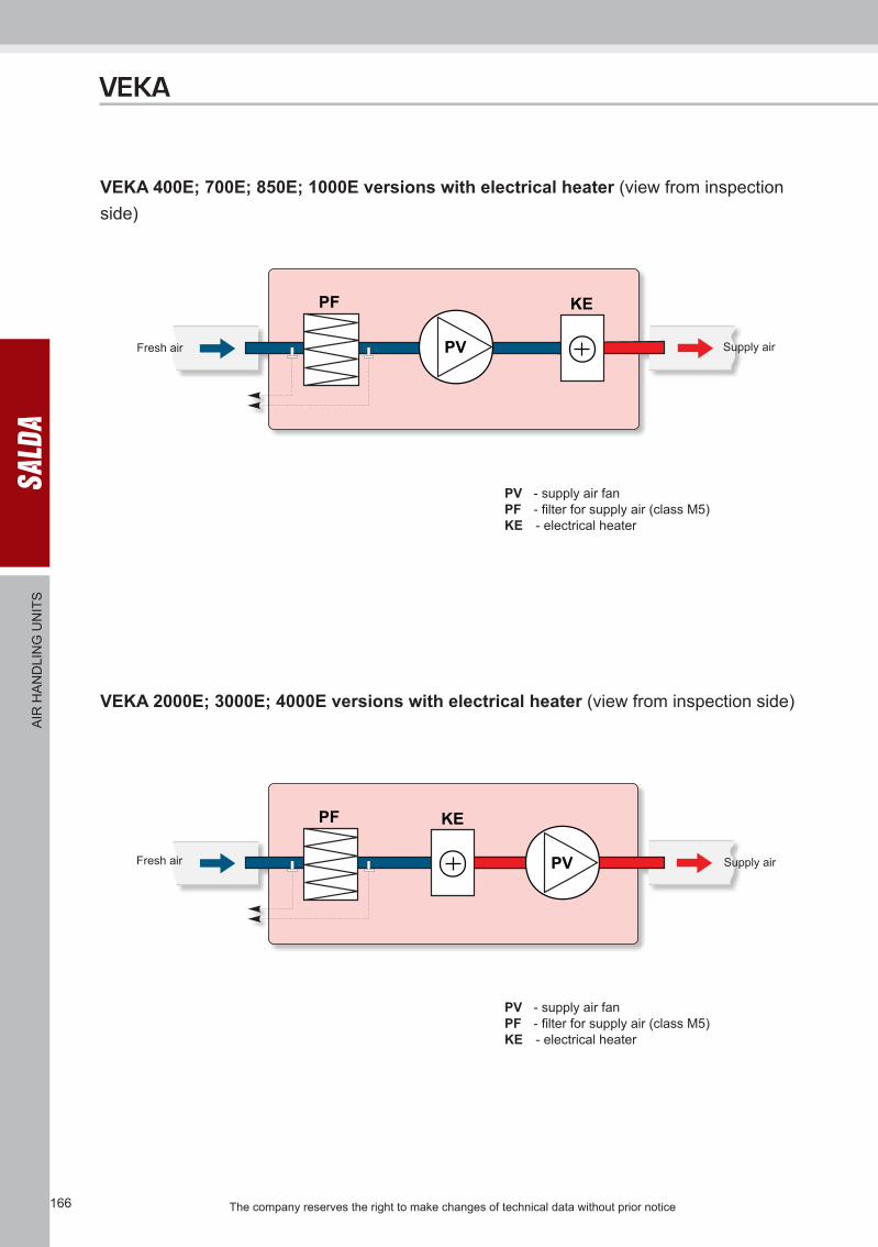
VEKA 400E; 700E; 850E; 1000E versions with electrical heater (view from inspection side)
PV - supply air fanPF - filter for supply air (class M5)KE - electrical heater
Fresh air Supply air
VEKA 2000E; 3000E; 4000E versions with electrical heater (view from inspection side)
PV - supply air fanPF - filter for supply air (class M5)KE - electrical heater
Fresh air Supply air

167The company reserves the right to make changes of technical data without prior notice
VEKA
AIR
HA
ND
LIN
G U
NIT
S
VEKA 1000W versions with water heater (view from inspection side)
VEKA 2000W; 3000W; 4000W versions with water heater (view from inspection side)
PV - supply air fanPF - filter for supply air (class M5)KV - water heaterM1 - optionally supplied mixing valve and motor
PV - supply air fanPF - filter for supply air (class M5)KV - water heaterM1 - optionally supplied mixing valve and motor
Fresh air
Fresh air
Supply air
Supply air

The company reserves the right to make changes of technical data without prior notice168
Wiring diagram No. 1C -Centrifugal fanD -Electrical heater
Wiring diagram No. 2
Wiring diagram No. 4
C -Centrifugal fanD -Electrical heater
Wiring diagram No. 3C -Centrifugal fanD -Electrical heater
C -Centrifugal fanD -Electrical heater
Wiring diagram No. 5C -Centrifugal fanD -Electrical heater
Wiring diagram No. 6C -Centrifugal fanD -Electrical heater
Wiring diagram No. 7C -Centrifugal fanD -Electrical heater
VEKA
AIR
HA
ND
LIN
G U
NIT
S
Wiring diagram No. 8C -Centrifugal fanD -Electrical heater
Wiring diagram No. 9C -Centrifugal fanD -Electrical heater
222
Wiring diagram No. 10A -Overheat protection with manual reset 100°CB -Overheat protection with automatical reset 50°CC -Centrifugal fanD -Electrical heater

169The company reserves the right to make changes of technical data without prior notice
VEKA
AIR
HA
ND
LIN
G U
NIT
S
Wiring diagram No. 12A -Overheat protection with manual reset 100°CB -Overheat protection with automatical reset 50°CC -Centrifugal fanD -Electrical heater
22
2
Wiring diagram No. 11A -Overheat protection with manual reset 100°CB -Overheat protection with automatical reset 50°CC -Centrifugal fanD -Electrical heater
C -Centrifugal fan
Wiring diagram No. 14 Wiring diagram No. 15C -Centrifugal fan
222
Wiring diagram No. 13A -Overheat protection with manual reset 100°CB -Overheat protection with automatical reset 50°CC -Centrifugal fanD -Electrical heater