veichi sd700 series servo system manual...sd700 series servo drives are mainly used for the occasion...
TRANSCRIPT
Contents
I SD700 Series Servo Technical Manual
Contents
Contents ................................................................................................................................................. I Abstract ....................................................................................................................................... 1 1.
Series Introduction ................................................................................................................ 1 1.1. Name of Each Part of the Servo Drive ................................................................................. 1 1.2. Basic Information of Servo Unit............................................................................................ 2 1.3.
Installation Dimensions ............................................................................................ 2 1.3.1. Installation Way ........................................................................................................ 3 1.3.2. Rated electrical parameters ..................................................................................... 3 1.3.3. Basic specifications .................................................................................................. 4 1.3.4.
System Diagram ................................................................................................................... 8 1.4. System Configuration Example............................................................................................ 9 1.5. Name the Drive ................................................................................................................... 10 1.6. Maintenance and Inspection of Servo Unit ........................................................................ 11 1.7.
Overhaul of Servo Motor ........................................................................................ 11 1.7.1. Overhaul of Servo Drive ......................................................................................... 11 1.7.2. Approximate Standards for Changing Internal Parts of Servo Units ..................... 11 1.7.3.
Panel Operation ....................................................................................................................... 12 2. Basic Operation .................................................................................................................. 12 2.1.
Keys’ Names and Functions of the Panel Operator .............................................. 12 2.1.1. Functions Switch .................................................................................................... 13 2.1.2. Status Display ......................................................................................................... 13 2.1.3.
Auxiliary Functions Operation of Fn group......................................................................... 14 2.2. Parameter Pn Group’s Operation....................................................................................... 14 2.3. Operations of Monitoring Display Un Group ...................................................................... 15 2.4.
Wiring and Connections ........................................................................................................... 16 3. Main Circuit Wiring.............................................................................................................. 16 3.1.
Terminals Explanation: ........................................................................................... 16 3.1.1. Wiring Diagram ....................................................................................................... 17 3.1.2. B/C/D-volume three-phase wiring diagram ............................................................ 18 3.1.3.
Definition of CN1 Terminal .................................................................................................. 19 3.1. CN7 USB Communication Terminal Connection ............................................................... 20 3.2. CN6A and CN6B Communication Terminal Connection.................................................... 20 3.3. CN5 Full Closed Loop Port................................................................................................. 21 3.4. Switch-Value Input Signal ................................................................................................... 23 3.5.
Input Signal Explanation......................................................................................... 23 3.5.1. Input Signal Configuration ...................................................................................... 24 3.5.2. Confirming the Input Status .................................................................................... 26 3.5.3.
Switching Output Signal ..................................................................................................... 27 3.6. Output Signal Explanation ...................................................................................... 27 3.6.1. Output Signal Configuration ................................................................................... 27 3.6.2. Confirming the Output Status ................................................................................. 28 3.6.3.
Connection with the Upper Device ..................................................................................... 29 3.7. Analog Input Circuit 3 ............................................................................................. 29 3.7.1.
Contents
II SD700 Series Servo Technical Manual
Position Instruction Input Circuit ............................................................................ 29 3.7.2. Connection example of open collector outtput ...................................................... 30 3.7.3. Sequence Control Input Circuit .............................................................................. 33 3.7.4. Sequence Output Loop .......................................................................................... 34 3.7.5.
Position Control Wiring Diagram ........................................................................................ 37 3.8. Speed Control Wiring Diagram .......................................................................................... 38 3.9.
Torque Control Wiring Diagram ........................................................................................ 39 3.10. CN2 Encoder Connection ................................................................................................. 40 3.11. Regenerative Resistor Connection .................................................................................. 40 3.12.
Connection of Regenerative Resistors ................................................................ 40 3.12.1. Selection of Regenerative Resistor.................................................................................. 40 3.13. Noise and High Harmonic Countermeasures .................................................................. 41 3.14.
Trial operation ........................................................................................................................... 41 4. Inspections and Notes before Trail Operation ................................................................... 41 4.1.
Conditions of the Servo Motor:............................................................................... 42 4.1.1. Conditions of the Servo Drive ................................................................................ 42 4.1.2. Installation ............................................................................................................... 42 4.1.3.
JOG trail operation ............................................................................................................. 42 4.2. Operation .................................................................................................................................. 43 5.
Basic Functions .................................................................................................................. 43 5.1. Quick Guide ............................................................................................................ 43 5.1.1. Servo Enable and Over-range Setting ................................................................... 43 5.1.2. Motor Rotation Direction ......................................................................................... 45 5.1.3. Stop Mode............................................................................................................... 45 5.1.4. Electromagnetic Brake ........................................................................................... 46 5.1.5. Regenerative Resistor ............................................................................................ 48 5.1.6. Overload ................................................................................................................. 48 5.1.7. Multi-turn Absolute Encoder ................................................................................... 49 5.1.8. Torque Limit ............................................................................................................ 50 5.1.9.
Position Mode ..................................................................................................................... 52 5.2. Quick Guide ............................................................................................................ 53 5.2.1. Basic Settings ......................................................................................................... 53 5.2.2. Deviation Clearance ............................................................................................... 56 5.2.3. Command Pulse Prohibition ................................................................................... 57 5.2.4. Positioning Approach .............................................................................................. 57 5.2.5. Positioning Completion ........................................................................................... 58 5.2.6. Command Pulse Input Magnification Switching .................................................... 59 5.2.7. Smooth Settings ..................................................................................................... 60 5.2.8. Frequency Output ................................................................................................... 61 5.2.9.
Speed Mode........................................................................................................................ 63 5.3. Quick Guide ............................................................................................................ 64 5.3.1. Basic Settings ......................................................................................................... 64 5.3.2. Soft Start ................................................................................................................. 67 5.3.3. Zero Fixed Functions .............................................................................................. 68 5.3.4. Rotation Detection Signal ....................................................................................... 69 5.3.5. Consistent Speed ................................................................................................... 70 5.3.6.
Torque Mode ....................................................................................................................... 71 5.4. Quick Guide ............................................................................................................ 72 5.4.1. Basic Settings ......................................................................................................... 72 5.4.2.

Contents
III SD700 Series Servo Technical Manual
Adjustment of Instruction Offset ............................................................................. 74 5.4.3. Speed Limit in Torque Control ................................................................................ 74 5.4.4.
Hybrid Control Mode Selection .......................................................................................... 74 5.5. Other Output Signals .......................................................................................................... 78 5.6.
Servo Ready Output Signal .................................................................................... 78 5.6.1. Warning Output Signal ........................................................................................... 78 5.6.2.
Timing.................................................................................................................................. 79 5.7. Power Enable ON Timing ....................................................................................... 79 5.7.1. Power-Off Enable OFF Timing ............................................................................... 80 5.7.2.
Adjustment ................................................................................................................................ 80 6. Adjustments ........................................................................................................................ 80 6.1.
Adjustments Steps .................................................................................................. 80 6.1.1. Safety Precautions When Adjusting ....................................................................... 81 6.1.2.
Robust Control .................................................................................................................... 83 6.2. Profile ...................................................................................................................... 83 6.2.1. Steps ....................................................................................................................... 84 6.2.2. Supplement ............................................................................................................. 84 6.2.3. Relevant Parameters .............................................................................................. 84 6.2.4.
Inertia Recognition .............................................................................................................. 86 6.3. Profile: ..................................................................................................................... 86 6.3.1. Steps ....................................................................................................................... 86 6.3.2. Supplyment ............................................................................................................. 86 6.3.3.
Intelligent Setting ................................................................................................................ 87 6.4. Profile ...................................................................................................................... 87 6.4.1. Steps ....................................................................................................................... 87 6.4.2. Supplyment ............................................................................................................. 89 6.4.3. Related Parameters................................................................................................ 90 6.4.4.
Bandwidth Setting ............................................................................................................... 91 6.5. Profile ...................................................................................................................... 91 6.5.1. Steps ....................................................................................................................... 91 6.5.2. Supplyment ............................................................................................................. 92 6.5.3. Related Parameters................................................................................................ 93 6.5.4.
Manual Adjustment Function .............................................................................................. 94 6.6. Servo Gain .............................................................................................................. 94 6.6.1. Gain Switching ........................................................................................................ 96 6.6.2. Speed Feedforward ................................................................................................ 99 6.6.3. Torque Feedforward .............................................................................................100 6.6.4. P/PI Switching.......................................................................................................100 6.6.5.
Accessibility ............................................................................................................................105 7. List of Auxiliary Functions .................................................................................................105 7.1. Displaying Alarm Logs (Fn000) ........................................................................................105 7.2.
Overview ...............................................................................................................105 7.2.1. Operating Procedure ............................................................................................106 7.2.2.
Clear Alarm Record (Fn001) ............................................................................................106 7.3. Summary ...............................................................................................................106 7.3.1. Operating Procedure ............................................................................................106 7.3.2.
Software Reset (Fn002) ...................................................................................................106 7.4. Summary ...............................................................................................................106 7.4.1. Operating Procedure ............................................................................................107 7.4.2.
Contents
IV SD700 Series Servo Technical Manual
Restoring Factory Parameters (Fn003) ...........................................................................107 7.5. Overview ...............................................................................................................107 7.5.1. Operating Procedure ............................................................................................107 7.5.2.
JOG Operation (Fn005) ....................................................................................................107 7.6. Summary ...............................................................................................................107 7.6.1. Operating Procedure ............................................................................................108 7.6.2.
Program JOG Operation (Fn006).....................................................................................108 7.7. Summary ...............................................................................................................108 7.7.1. Operating Procedure ............................................................................................109 7.7.2.
Automatic Adjustment of Instruction Offset (Fn100) ........................................................109 7.8. Summary ...............................................................................................................109 7.8.1. Operating Procedure ............................................................................................109 7.8.2.
Speed Command Offset Manual Adjustment (Fn101)..................................................... 110 7.9. Summary ............................................................................................................... 110 7.9.1. Operating .............................................................................................................. 110 7.9.2. Summary ............................................................................................................... 110 7.9.3. Operating Procedure ............................................................................................ 111 7.9.4.
Current Offset Automatic Adjustment (Fn103) ............................................................... 111 7.10. Summary............................................................................................................. 111 7.10.1. Operating Procedure .......................................................................................... 111 7.10.2.
Current Offset Manual Adjustment (Fn104) ................................................................... 111 7.11. Overview ............................................................................................................. 111 7.11.1. Operating Procedure .......................................................................................... 112 7.11.2.
Initializing the Detection Value of Vibration Detection (Fn105) ..................................... 112 7.12. Summary............................................................................................................. 112 7.12.1. Operating Procedure .......................................................................................... 113 7.12.2.
Bandwidth Settings (Fn303) ........................................................................................... 113 7.13. Summary............................................................................................................. 113 7.13.1.
7.14.2 Operating Procedure ........................................................................................... 114 EasyFFT (Fn401)............................................................................................................ 114 7.14.
Summary............................................................................................................. 114 7.14.1. Operating Procedure .......................................................................................... 115 7.14.2.
Online Vibration Monitoring (Fn402) .............................................................................. 115 7.15. Overview ............................................................................................................. 115 7.15.1. Operating Procedure .......................................................................................... 115 7.15.2.
Function Code Instructions .................................................................................................... 116 8. Basic Control Related Pn0 Group Parameters ................................................................ 116 8.1. Gain Related Pn1 Group ..................................................................................................121 8.2. Position Related Pn2 Group Parameters .........................................................................128 8.3. Speed Related Pn3 Group Parameters ...........................................................................133 8.4. Torque Related Pn4 Group Parameters...........................................................................135 8.5. Jogging Related Pn0 Group Parameters .........................................................................137 8.6. Switch Configuration Related Pn6 Group Parameters ....................................................137 8.7. Expansion Related Pn7 Group Parameters.....................................................................140 8.8.
Monitoring Parameters ...........................................................................................................141 9. Fault Code and Countermeasures.........................................................................................144 10.
Fault Code ......................................................................................................................144 10.1. Warning Code .................................................................................................................149 10.2.
Communication.......................................................................................................................150 11.

Contents
V SD700 Series Servo Technical Manual
Communication introduction ...........................................................................................150 11.1. RS485 communication protocol description...................................................................150 11.2. Communication frame structure .....................................................................................150 11.3. Command code and communication data description...................................................151 11.4. Communication frame error check mode: ......................................................................153 11.5. Error message response ................................................................................................154 11.6.
Host Debugging Instruction ....................................................................................................155 12. System Requirements ....................................................................................................155 12.1.
System Configuration .........................................................................................155 12.1.1. Connection Configuration ...................................................................................155 12.1.2.
Main Interface .................................................................................................................156 12.2. Features ..........................................................................................................................158 12.3. Real-Time Monitoring .....................................................................................................162 12.4. Auxiliary Functions ..........................................................................................................163 12.5.
JOG .....................................................................................................................163 12.5.1. Inertia Identification ............................................................................................164 12.5.2. Mechanical Characteristics ................................................................................166 12.5.3. Analysis ...............................................................................................................168 12.5.4. Bandwidth setting ...............................................................................................168 12.5.5. Offset Adjustment ...............................................................................................170 12.5.6. Soft Reset ...........................................................................................................171 12.5.7. Restoring the Factory Value ...............................................................................171 12.5.8. Fault Information .................................................................................................172 12.5.9.
Digital Oscilloscope ........................................................................................................172 12.6. Real-Time Acquisition .........................................................................................175 12.6.1. Trigger Acquisition ..............................................................................................175 12.6.2. Graphic Operations ............................................................................................176 12.6.3.
Others .............................................................................................................................181 12.7. Window Display ..................................................................................................181 12.7.1. Help .....................................................................................................................181 12.7.2.

Abstract
1
Abstract 1.
Series Introduction 1.1.
SD700 series servo drives are mainly used for the occasion of high speed, high frequency and high positioning accuracy. The servo unit can maximize the performance of the machine in the shortest time, which can improve the production efficiency.
Name of Each Part of the Servo Drive 1.2.
Motorencoderlineport
Multi-functioncontrolport
CommunicationRJ45
Host computermicro USB
Operationkeyboard
Digital display tube
Rotate thekeyboard cover
Top full-closedloop port
Heat sink
Servo nameplate
Power Indicator
Main circuitpower
Control power
Motor power
Safetygrounding
Braking unit
Main circuit powerprotection cover
Abstract
2
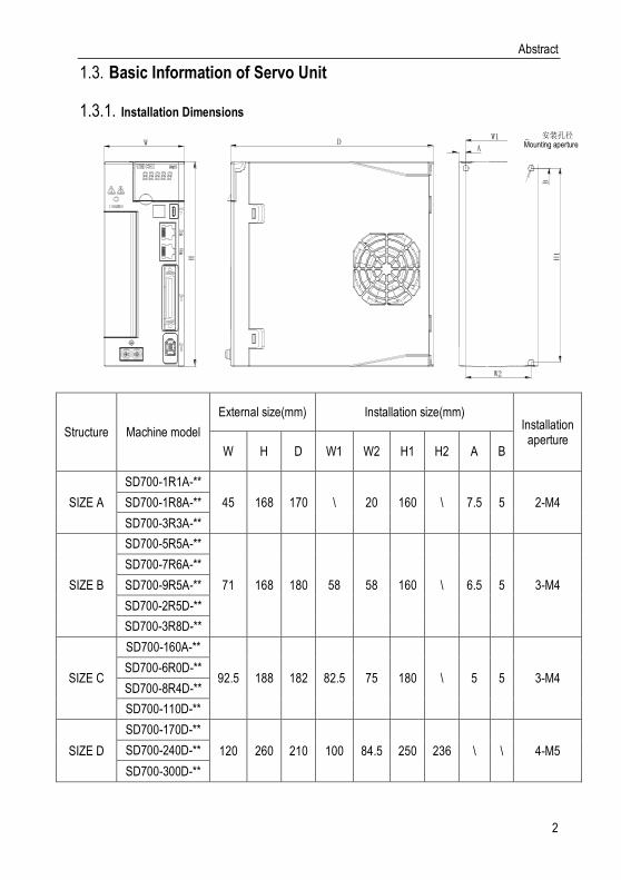
Basic Information of Servo Unit 1.3.
Installation Dimensions 1.3.1.
W
H
DW1
H1
B
A
安装孔径
W2
Structure Machine model
External size(mm) Installation size(mm) Installation aperture
W H D W1 W2 H1 H2 A B
SIZE A
SD700-1R1A-**
45 168 170 \ 20 160 \ 7.5 5 2-M4 SD700-1R8A-**
SD700-3R3A-**
SIZE B
SD700-5R5A-**
71 168 180 58 58 160 \ 6.5 5 3-M4
SD700-7R6A-**
SD700-9R5A-**
SD700-2R5D-**
SD700-3R8D-**
SIZE C
SD700-160A-**
92.5 188 182 82.5 75 180 \ 5 5 3-M4 SD700-6R0D-**
SD700-8R4D-**
SD700-110D-**
SIZE D
SD700-170D-**
120 260 210 100 84.5 250 236 \ \ 4-M5 SD700-240D-**
SD700-300D-**
Mounting aperture
Abstract
3
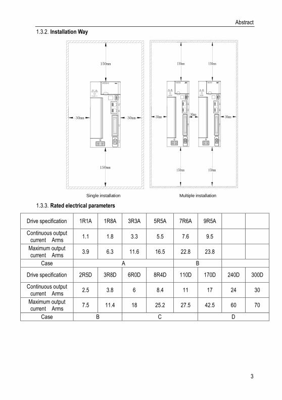
Installation Way 1.3.2.
150mm
30mm
150mm
30mm
单台安装空间
150mm
30mm30mm30mm
150mm
150mm 150mm
多台安装空间
Single installation Multiple installation
Rated electrical parameters 1.3.3.
Drive specification 1R1A 1R8A 3R3A 5R5A 7R6A 9R5A
Continuous output current Arms
1.1 1.8 3.3 5.5 7.6 9.5
Maximum output current Arms
3.9 6.3 11.6 16.5 22.8 23.8
Case A B
Drive specification 2R5D 3R8D 6R0D 8R4D 110D 170D 240D 300D
Continuous output current Arms
2.5 3.8 6 8.4 11 17 24 30
Maximum output current Arms
7.5 11.4 18 25.2 27.5 42.5 60 70
Case B C D

Abstract
4
Basic specifications 1.3.4.
Project Specifications
Control Mode IGBT, PWM Control, Sine wave current drive mode
Feedback Rotary Motor Combination
Serial communication encoders: 17-bit, 20-bit, 24-bit (absolute encoder)
Pulse encoder: Provincial linear encoder: 2500 line
Rotary transformer type encoder
Environmental conditions
Environment temperature -5℃~55℃(55 ° C ~ 60 ° C, can reduce the
rated value to use)
Storage temperature -20℃~85℃
Environmental humidity Less 95%RH(No freezing, no condensation)
Storage humidity Less 95%RH(No freezing, no condensation)
Vibration resistance 4.9m/s²
Impact resistance 19.6m/s²
Protection level IP20
Cleanliness
Non-corrosive and flammable gas
No water, oil, pharmacy splash
Dust, salt, and metal powder are less in the environment
Altitude Below 1000m (1000m~2000m, can reduce
the rated value to use)
others No static electricity interference, strong electric field, strong magnetic noise, radiation, etc.
Applicable standard EN 61800-5-1:2007 EN 61800-3:2004/A1:2012
Installation type Base mounting Type: All models
Shelf mounting type: All models
Performance
Speed control range 1:6000 (The lower limit of the speed control range is the value under non-stop condition at the rated torque load)
Speed fluctuation rate
Load fluctuation Below ± 0.01% of rated speed (load fluctuation: 0%~100%)
Voltage fluctuation Rated speed 0% (rated voltage ± 10%)
Temperature fluctuation
Below ± 0.1% of rated speed (temperature fluctuation: 25± 25° C)
Torque control accuracy ± 1%
Soft-start time setting 0~10s (acceleration and deceleration can be
set separately)

Abstract
5
Communication
function
RS-485
1:N communication
When RS-485 port, N max = 127 stations
Axis address setting
Through parameter setting
USB communication
Connected equipment
Computer
According to USB1.1 specification (12M)
Display function Charge indicator
Panel operation function Push button switch × 4
Input and output signals
Encoder divider pulse output A-phase, B-phase, and C-phase: linear drive transmission frequency pulse number, can free to set
Sequence input signal
Fixed input
Operating voltage range: DC 5V± 5%
Input points: 1 point
Encoder absolute data request input (SEN) signal
Assignable input signal
Operating voltage range: DC24V± 20%
Input points: 9 points
Input method: common collector input, common emitter input
Input signal
Servo ON (/S-ON)
P operation/P-CON
Home reset deceleration switch signal (/DEC)
Forward drive prohibition (P-OT), reverse drive prohibition (N-OT)
Alarm reset (/ALM-RST)
Forward external torque limit (/P-CL), reverse external torque limit (/N-CL)
Speed rotation direction selection (/SPD-D) signal
Control Mode Switch (/C-SEL)
Zero Fixed (/ZCLAMP)
Command Pulse Disable (/INHIBIT)
Magnetic pole detection input (/P-DET) signal
Gain switching (/G-SEL)
Command pulse input override switch (/PSEL)
SEN input (/SEN) signal
Assignable signals and change positive/negative logic
Sequential output Fixed output Operating voltage range: DC5V~DC30V

Abstract
6
signal Output points: 1 point
Output signal: servo alarm (ALM)
Assignable output signal
Operating voltage range: DC5V~DC30V
Output points: 3 points
Input method: opt coupler output (isolated type)
Output signal
Positioning completed (/COIN)
Rotary checkout (/TGON)
Servo ready (/S-RDY)
Torque Limit Detection (/CLT)
Speed Limit Checkout (/VLT)
Brakes (/BK)
Warning (/WARN)
Locate nearby (/NEAR)
Assignable signals and change positive/negative logic
Dynamic brake Operation in the main circuit power OFF, servo alarm, servo OFF, and over-travel (OT)
Regenerative Function built-in
Over-travel (OT) protection Dynamic brake (DB) stop, deceleration stop or free-running stop during P-OT, N-OT input operation
Protective function Over-current, over-voltage, under-voltage, overload, regenerative failure, etc.
Accessibility function Gain adjustment, alarm records, JOG operation, origin search, etc.
Security function
Input STO: Base of the power module block signal
Control method
Position Control
Feed forward compensation 0%~100%
Location reach arrange 0~1073741824 instruction unit
Input signal
Command pulse
Command pulse form
Choose any of the followings
Symbol & pulse sequence, CW+CCW pulse sequence, 90° phase difference two-phase pulse
Input form Linear drive, open collector
Maximum input frequency
Line driver
Symbol + pulse sequence, CW + CCW pulse sequence: 4Mpps
90° phase difference two-phase pulse: 1Mpps
Open collector

Abstract
7
Symbol + pulse sequence, CW + CCW pulse sequence: 200 Kpps
90° phase difference two-phase pulse: 200Kpps
Input override switch
1~100 times
Clear signal Position deviation clearing
Speed control
Soft-start time setting 0~10s (acceleration and deceleration can be
set separately)
input signal
Command voltage
Maximum input voltage: ± 10V (Forward rotation of motor when positive voltage is commanded)
Rated speed at DC6V [factory setting]
Can change input gain setting
input resistance About 14KΩ
Loop time parameter 30μs
Internally set speed control
Rotation direction selection
Use P operation signal
Speed selection
Using Forward/Reverse External Torque Limit Signal Input
Stop or change to other control mode when both sides are OFF
Torque control
input signal
Command voltage
Maximum input voltage: ± 10V (positive rotation of motor when positive voltage is commanded)
Rated speed at DC6V [factory setting]
Can change input gain setting
Input resistance About 14KΩ
Loop time parameter 16μs

Abstract
8
System Diagram 1.4.
Over-temperature/current protection
Dynamicbrake circuit
M
L1
L2
L3
Maincircuitpower
Rheostat
Charge
B1/⊕
2
B2 B3
Voltage sampling
Delay Drive Temperature sampling
Gate drive
Current sampling
Controlpower
RheostatL1C
L2CControlpower
ARM+FPGA
CN7 CN6
MicroUSB Dual RJ45 bus interface Full-closed loop and 2500 line interface
I/O
A/D
CN5
Input and output signals
Command voltage input
Encoder divider pulse output
Command pulse input
U
V
W
CN1
CN2
Servo motor
ENC
Fan
Bus encoderinterface
Panel operator
Abstract
9
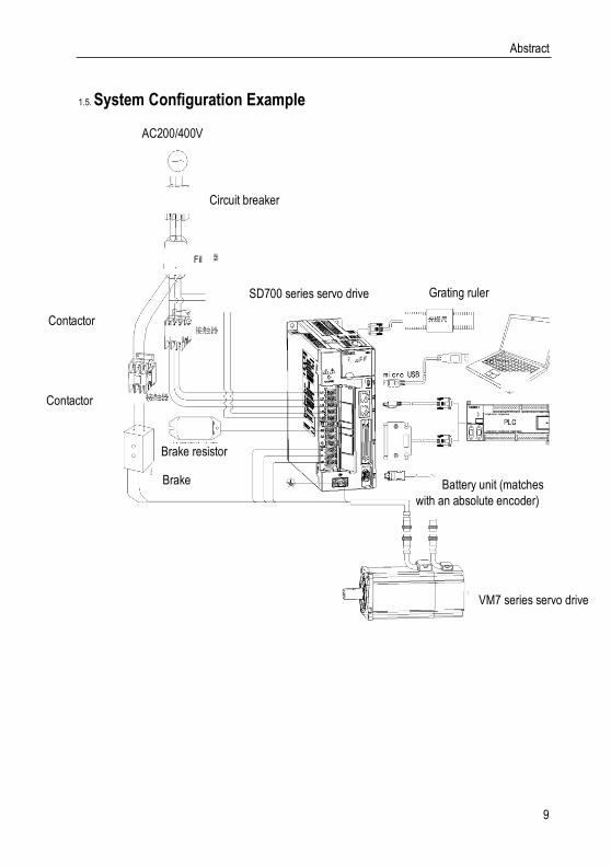
System Configuration Example 1.5.
AC200/400V
Circuit breaker
Filter
Brake resistor
Brake power
SD700 series servo drive
Battery unit (matches
with an absolute encoder)
VM7 series servo drive
Grating ruler
Contactor
Contactor

Abstract
10
Name the Drive 1.6.
SD700-3R3A-PA*A B C D E F G
Field ID Field Explanation
A SD:Servo product code
B 700:Product series
C
Current class:
1R1:1.1A 1R8:1.8A 3R3:3.3A 5R5:5.5A 7R6:7.6A 9R5:9.5A
2R5:2.5A 3R8:3.8A 6R0:6A 8R4:8.4A 110:11A 170:17A 240:
24A 300:30A
D Input voltage class:
A:220VAC;D:400VAC
E
Type:
P: pulse type; S: standard type; C: CAN open bus type; N: Ether CAT bus type; M: MECHATROLINK-II bus type; L: MECHATROLINK-III bus type
F
Supported encoder types:
A Absolute type
B Incremental
T Rotary transformer type
G Product management number, standard product default.
Difference functions between different types:
Code model Input pulse
16-bit analog value
Full closed loop
RS485 CAN open
Ether CAT
MECHATRO
LINK Ⅱ
MECHATRO
LINK Ⅲ
P Pulse type √ × × √ × × × ×
S Standard type √ √ √ √ × × × ×
C CAN type × × × × √ × × ×
N Ether CAT type × × × × × √ × ×
M MECHATROLINK
Ⅱ type × × × × × × √ ×
L MECHATROLINK
Ⅲ type × × × × × × × √
*1.M-II type refers to the servo unit interface specification for MECHATROLINK-II communication command type
*2.M-III type refers to the servo unit interface specification for MECHATROLINK-III communication command type

Abstract
11
Maintenance and Inspection of Servo Unit 1.7.
The servo system is made up of many parts. The equipment performs its functions only when all the parts work properly. In mechanical parts and electronic parts, some parts need to be maintained depending on the conditions of use. It must be regularly checked or replaced according to the service-time to ensure that the servo motor and servo drive can operate normally for a long time.
Overhaul of Servo Motor 1.7.1.
Since the AC servo motor does not have the electric brush so that only a simple daily maintenance is required. The maintenance period in the table is a rough standard. Please judge and determine the most appropriate time for repair according to the conditions of use and use environment.
Inspect items Inspect
time The essentials of inspection
and maintenance Notes
Vibration and sound confirmation
every day Tactile and auditory judgments No increase compared to usual
Appearance overhaul
According to the insult
Erasing with a cloth or cleaning with an air gun
-
Insulation resistance measurement
At least once a year
Disconnect the servo unit and measure the insulation resistance with a 500V megger. Resistance value exceeding 10MΩ is normal
When it is 10MΩ or less, please contact our maintenance department.
Replacement of oil seals
At least once every 5000 hours
Please contact our agents or technical support.
Only servo motor with oil seal.
Comprehensive maintenance
At least once every 20,000 hours or 5 years
-
Overhaul of Servo Drive 1.7.2.
Although the servo drive unit does not require daily inspections, it should be overhauled more than once a year.
Maintenance project
Inspect time The essentials of inspection and maintenance
Notes
Appearance maintenance more than
once a year
No garbage, dust, oil traces, etc. Erasing with a cloth or cleaning with an air gun
Loose screws
Wiring board, connector mounting screws and so on must not loosen
Please tighten
Approximate Standards for Changing Internal Parts of Servo Units 1.7.3.
Electrical and electronic parts are subject to mechanical wear and aging. To ensure safety,

Panel Operation
12
please do regular inspections. In addition, please refer to the following table for the standard number of years of replacement, and contact our agency or sales office. After the inspection, we will judge whether we need to replace the parts. The servo unit serviced by our company has its user parameters adjusted back to the factory settings. Be sure to reset the user parameters before use by yourself.
Parts’ name Standard replacement
period Conditions of use
Cooling fan 4~5 years
Ambient temperature: annual average 30° C Load rate: 80% or less Operating rate: 20 hours or less
Smoothing capacitor 7~8 years
Relay According to actual use conditions
Aluminum electrolytic capacitors on printed circuit boards
5 years
Panel Operation 2.
Basic Operation 2.1.
Keys’ Names and Functions of the Panel Operator 2.1.1.
The panel operator consists of panel monitor and keys. The panel operator could display condition, operate the accessory functions, set parameters and monitor the motions of the drive unit. The panel operator keys’ names and functions are shown as below:
MODE
SET
DATA

Panel Operation
13
Keys’ name Functions
MODE/SET key
Shift the function modes
Confirm parameter settings
Operate the accessory functions
UP key Select parameters up or increase the value, switch between high, medium,
and low segment values in multiple segment display parameters
▼ DOWN key Select parameters down or decrease the value, switch between high,
medium, and low segment values in multiple segment display parameters
DATA/SHIFT key
Press and hold the DATA/SHIFT button for about 1 second to enter or exit
Short press to move to the left one (when flashing)
Caution! Pressing the Up and Down keys at the same time could reset the drive alarm, but remember to exclude
causes of the alarm before reset the drive alarm.
Functions Switch 2.1.2.
Press the MODE/SET key, the function will be switched like this shown as below:
Parameters setting
Aux functions
MonitoringStatus display
MODE/SET MODE/SET MODE/SET
MODE/SET
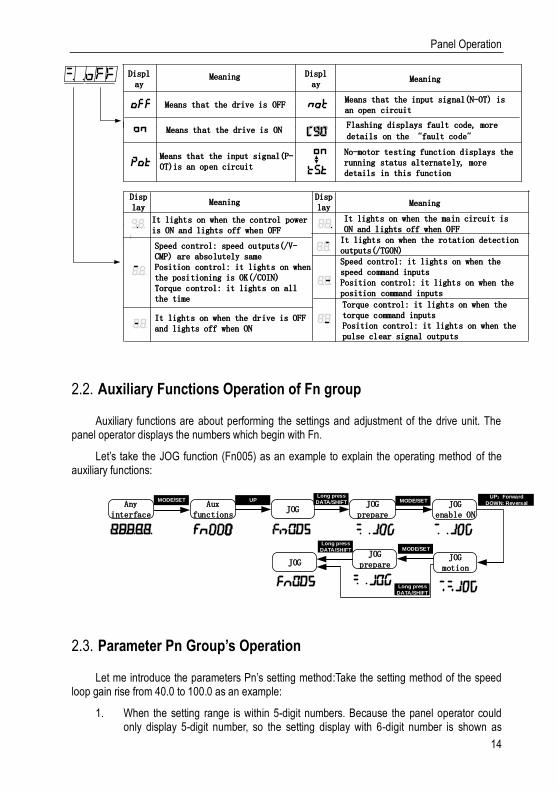
Status Display 2.1.3.
The method of judging the status display is as follows:
Panel Operation
14
Display
Meaning MeaningDisplay
Means that the drive is OFF
Means that the drive is ON
Means that the input signal(P-OT)is an open circuit
Means that the input signal(N-OT) is an open circuit
Flashing displays fault code, more
details on the �fault code
No-motor testing function displays the running status alternately, more details in this function
Display
Meaning MeaningDisplay
It lights on when the control power is ON and lights off when OFF
Speed control: speed outputs(/V-CMP) are absolutely samePosition control: it lights on when the positioning is OK(/COIN)Torque control: it lights on all the time
It lights on when the drive is OFF and lights off when ON
It lights on when the main circuit is ON and lights off when OFFIt lights on when the rotation detection outputs(/TGON)Speed control: it lights on when the speed command inputs Position control: it lights on when the position command inputs
Torque control: it lights on when the torque command inputsPosition control: it lights on when the pulse clear signal outputs
Auxiliary Functions Operation of Fn group 2.2.
Auxiliary functions are about performing the settings and adjustment of the drive unit. The panel operator displays the numbers which begin with Fn.
Let’s take the JOG function (Fn005) as an example to explain the operating method of the auxiliary functions:
JOGAux
functionsJOG
prepareAny
interface
MODE/SET UPLong press
DATA/SHIFT JOG enable ON
MODE/SETUP:Forward
DOWN: Reversal
JOG motion
JOG prepareJOG
MODE/SETLong press
DATA/SHIFT
Long press
DATA/SHIFT
Parameter Pn Group’s Operation 2.3.
Let me introduce the parameters Pn’s setting method:Take the setting method of the speed loop gain rise from 40.0 to 100.0 as an example:
1. When the setting range is within 5-digit numbers. Because the panel operator could only display 5-digit number, so the setting display with 6-digit number is shown as

Panel Operation
15
below:
2. When the setting range is beyond 6-digit numbers:
High digit Middle digit Low digit
They appear only when the number is a negative
Operations of Monitoring Display Un Group 2.4.
This function could monitor setting command values of the drive unit, the status of input and output signals and internal conditions of the drive unit. The panel operator displays the numbers which begin with Un, then let’s take this function as an example to explain the operating method of the monitoring display: when the motor speed is 3000rpm:
Aux functions
Enter into monitoring
Any interface
MODE/SETLong press
DATA/SHIFT
Wiring and Connections
16
Wiring and Connections 3.
Main Circuit Wiring 3.1.
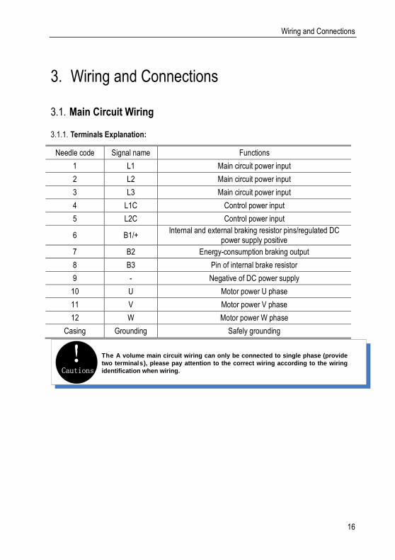
Terminals Explanation: 3.1.1.
Needle code Signal name Functions
1 L1 Main circuit power input
2 L2 Main circuit power input
3 L3 Main circuit power input
4 L1C Control power input
5 L2C Control power input
6 B1/+ Internal and external braking resistor pins/regulated DC
power supply positive
7 B2 Energy-consumption braking output
8 B3 Pin of internal brake resistor
9 - Negative of DC power supply
10 U Motor power U phase
11 V Motor power V phase
12 W Motor power W phase
Casing Grounding Safely grounding
Cautions! The A volume main circuit wiring can only be connected to single phase (provide
two terminals), please pay attention to the correct wiring according to the wiring
identification when wiring.
Wiring and Connections
17
Wiring Diagram 3.1.2.
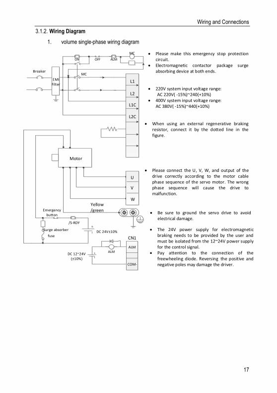
1. volume single-phase wiring diagram
Yellow/green
Surge absorber
Motor
fuse
BreakerMC
MC
ALM
COM-
ALM
ALMON OFF
DC 12~24V(±10%)
DC 24V±10%
CN1
220V system input voltage range: AC 220V( -15%)~240(+10%) 400V system input voltage range:
AC 380V( -15%)~440(+10%)
When using an external regenerative braking resistor, connect it by the dotted line in the figure.
Please connect the U, V, W, and output of the drive correctly according to the motor cable phase sequence of the servo motor. The wrong phase sequence will cause the drive to malfunction.
Be sure to ground the servo drive to avoid electrical damage.
The 24V power supply for electromagnetic braking needs to be provided by the user and must be isolated from the 12~24V power supply for the control signal.
Pay attention to the connection of the freewheeling diode. Reversing the positive and negative poles may damage the driver.
Please make this emergency stop protection circuit.
Electromagnetic contactor package surge absorbing device at both ends.
EMI Filter
/S-RDY
Emergency button
U
V
W
B1/+
B2
-
L1
L2
L1C
L2C

Wiring and Connections
18
B/C/D-volume three-phase wiring diagram 3.1.3.
Yellow/green
Surge absorber
Motor
Fuse
Breaker
MC
MC
ALM
COM-
ALM
ALMON OFF
DC 12~24V(±10%)
DC 24V±10%
CN1
L1
L2
L3
L1C
L2C
220V system input voltage range: AC 220V( -15%)~240(+10%) 400V system input voltage range: AC 380V( -15%)~440(+10%)
Please connect the U, V, W, and output of the drive correctly according to the motor cable phase sequence of the servo motor. The wrong phase sequence will cause the drive to malfunction.
Do not disconnect short wires between B2 and B3 unless using an external regenerative braking resistor.
When using an external regenerative braking resistor, disconnect the short wiring between B2 and B3 and connect them by the dotted line in the figure.
Be sure to ground the servo drive to avoid electrical damage.
T he 24V power supply for electromagnetic braking needs to be provided by the user and must be isolated from the 12~24V power supply for the control signal.
Pay attention to the connection of the freewheeling diode. Reversing the positive and negative poles may damage the driver.
Please make this emergency stop protection circuit. Electromagnetic contactor package surge absorbing
device at both ends.EM I
Filter
/S-RDY
Emergency button
U
V
W
B1/+
B2
B3
-
Wiring and Connections
19
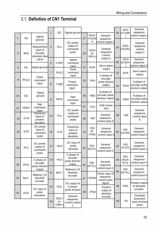
Definition of CN1 Terminal 3.1.
2 SGSignal
ground
4 SEN
Requirement
input of
encoder
absolute data
(SEN)
6 SG Signal ground
Signal ground
3 PL1
OC power
output of
command
pulse
5 V-REF
Speed
command
input
1 SG
8 /PULSPulse
command
input
7 PULS
Pulse
command
input
10 SG
Signal
ground
9 T-REFTorque
command
input
27
/SO2+
(TGON
+)
General
sequence
control output 2
29
/SO3+
(S-
RDY+)
General
sequence
control
output 3
31 ALM+Servo alarm
output
33 PAO
A phase of
encoder
pulse division
output
35 PBO
B phase of
encoder pulse
division output
26
/SO1-
(V-CMP-
)
General
sequence
control output 2
28/SO2-
(TGON-)
General
sequence
control
output 2
30/SO3-
(S-RDY-
)
General
sequence
control output 3
32 ALM-Servo alarm
output
34 /PAO
A phase of
encoder pulse
division output
11 SIGNSign
command
input
36 /PBO
B phase of
encoder pulse
division output
12 /SIGN
Sign
command
input
37 STOSafe torque
limit
13 PL2
OC power
output of
command
pulse14 /CLR
Clearance
input of
position
deviation
39 /SI9
General
sequence
control input 9
/SI838
General
sequence
control input
8
16 OCP
OC power
input of
command
pulse
CLR
Clearance
input of
position
deviation
15 41
/SI3
(P-
CON)
General
sequence
control input 340
/SI0
(/S-ON)
General
sequence
control input 0
18 PL3
OC power
output of
command
pulse
17 OCS
OC input of
pulse
direction 43/SI2
(N-OT)
General
sequence
control input 2
42/SI1
(P-OT)
General
sequence
control input 1
20 /PCO
C phase of
encoder
pulse division
output
19 PCO
C phase of
encoder
pulse division
output
44
/SI4
(/ALM-
RTS)
General
sequence
control input 4
22 BAT-
Battery(-) of
absolute
encoder
21 BAT+
Battery(+) of
absolute
encoder
45/SI5
(/P-CL)
General
sequence
control input 5
46/SI6
(/N-CL)
General
sequence
control input 6
47 +24VIN
Power input of
sequence
control input
signal48 PSO
Position output
of absolute
encoder
24 OCS
OC input of
pulse
clearance
23 OCZ
OC output of
Z phase
pulse division49 /PSO
Position
output of
absolute
encoder
25/SO1+
(V-
CMP+)
General
sequence
control output
1
50 TH
Overheat
protection
input of linear
motor

Wiring and Connections
20
Note: When using multi-turn absolute encoder, please pay attention to the connection of battery and serial data. For the setting of multi-turn absolute encoder.
CN7 USB Communication Terminal Connection 3.2.
Pin number Name Function
1 VBUS External power supply +5V
2 D- Data-
3 D+ Data+
4 - Unused
5 GND Ground
CN6A and CN6B Communication Terminal Connection 3.3.
引脚8
引脚1
引脚8
引脚1
CN6A
CN6B
Depending on the model, the definition of the port is different. When using the model, you need to confirm the definition of the interface. For the model identification, see "1.6 Drive Naming".
The field identification bit E is P: pulse type; S: standard type; C: CANopen bus type.
CN6A/CN6B Interface definition
Pin number Signal name Function Pin number Signal name Function
1 CANH CAN Data+ 6 -
Pin 8 Pin 1 Pin 8
Pin 1

Wiring and Connections
21
2 CANL CAN Data- 7 GND 485 Ground
3 CANG CAN Ground 8 - -
4 485- 485 Data- Case shield shield
5 485+ 485 Data+
The field identification bit E is M: MECHATROLINK-II bus type.
CN6A/CN6B Interface definition
Pin
number Signal name Function
1 SRD+ M-II Data+ 6 - -
2 SRD- M-II Data- 7 - -
3 - - 8 - -
4 - - Case Shield Shield
5 - -
The field identification bit E is N: EtherCAT bus type; L: MECHATROLINK-III bus type.
CN6A/CN6B Interface definition
Pin number Signal name Function Pin Signals Function
1 TX+ Data sending+ 6 RX- Data accept-
2 TX- Data sending- 7 - -
3 RX+ Data accept+ 8 - -
4 - - Case Shield Shield
5 - -
For the simultaneous use of multiple drives, the cascading mode is CN6A, CN6B is out, the cascading cable is below 50cm, and the last CN6B needs to be connected to the terminating resistor as appropriate.
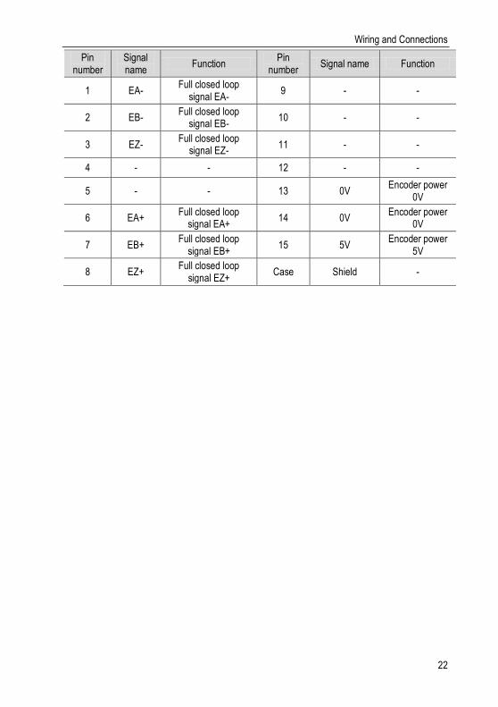
CN5 Full Closed Loop Port 3.4.
12345
1112131415
678910
2500 line encoder and full closed loop interface
Wiring and Connections
22
Pin number
Signal name
Function Pin
number Signal name Function
1 EA- Full closed loop
signal EA- 9 - -
2 EB- Full closed loop
signal EB- 10 - -
3 EZ- Full closed loop
signal EZ- 11 - -
4 - - 12 - -
5 - - 13 0V Encoder power
0V
6 EA+ Full closed loop
signal EA+ 14 0V
Encoder power 0V
7 EB+ Full closed loop
signal EB+ 15 5V
Encoder power 5V
8 EZ+ Full closed loop
signal EZ+ Case Shield -

Wiring and Connections
23
Switch-Value Input Signal 3.5.
Input Signal Explanation 3.5.1.
Control mode
Signal name Needle number
Function number and description
Normal
/S-ON
Allocated signal (38~46)
0x01 Control signal of servo motor ON/OFF (power on/off)
POT 0x02
Prohibited forward rotation drive When the mechanical movement exceeds the movable range, stop the servo motor drive (over travel prevention function)
NOT 0x03
Prohibited reverse drive When the mechanical movement exceeds the movable range, stop the servo motor drive (over-travel prevention function)
/ALM-RST 0x04 Alarm clear
/P-CON 0x05
When the P action command signal is ON, the speed control loop is switched from PI (proportional, integral) control to P (proportional) control.
/TLC 0x06 Torque limit switching Use when changing the torque limit during operation
/SPD-D 0x08 used to change the direction of motor control in internal speed,
/SPD-A 0x09 When used as internal speed mode, it is used to select the internal speed command /SPD-B 0x0A
/C-SEL 0x0B Control mode switching, used as a switching control mode when the control mode is mixed mode
/ZCLAMP 0x0C Zero fixed signal speed mode, used as a fixed zero.
/INHIBIT 0x0D Pulse input inhibit when used in position mode, it is used as disable pulse input count
/G-SEL 0x0E Gain switching gain switching to manual gain switching used as a switching gain
/PSEL 0x10 Command pulse input override switch position mode, used as switching pulse input override signal
+24VIN 47
Use when the sequence signal is input with the control power supply. Operating voltage range: +11V to +25V (please provide your own +24V power supply.)
Wiring and Connections
24
SEN 4 Enter the signal that requires initial data when using an absolute encoder
BAT+ BAT-
21 22
Spare battery connection pin for absolute encoder. Note: do not connect when using an encoder cable with a battery pack.
Speed V-REF 5(6) Enter the speed command. Maximum input voltage: ± 10V
Position
PULS /PULS SIGN /SIGN
7 8 11 12
Set any of the following input pulse patterns. Symbol + pulse sequence CW+CCW pulse sequence 90° phase difference 2-phase pulse
CLR /CLR
15 14
Clear position deviation during position control
Torque T-REF 9(10) Enter the torque command and the maximum input voltage: ± 10V
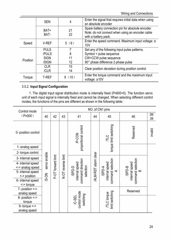
Input Signal Configuration 3.5.2.
1. The digital input signal distribution mode is internally fixed (Pn600=0). The function servo unit of each input signal is internally fixed and cannot be changed. When selecting different control modes, the functions of the pins are different as shown in the following table:
Control mode
(Pn000)
NO. of CN1 pins
40 42 43 41 44 45 46 38/39
0- position control
/S-O
N
se
rvo
enab
le
P-O
T fo
rwar
d lim
it
N-O
T r
ever
se li
mit
/P-C
ON
prop
ortio
nal c
ontr
ol
/ALM
-RS
T a
larm
cle
ar
/TLC
torq
ue li
mit
switc
hing
Res
erve
d
inva
lid
1- analog speed
2- torque control
3- internal speed
/SP
D-D
inte
rnal
spe
ed
com
man
d di
rect
ion
sele
ctio
n
/SP
D-A
inte
rnal
spe
ed
com
man
d se
lect
ion
A
/SP
D-B
inte
rnal
spe
ed
com
man
d se
lect
ion
B
4- internal speed <-> analog speed
5- internal speed <-> position
6- internal speed <-> torque
7- position <-> analog speed
/C-S
EL
cont
rol m
ode
switc
hing
/TLC
torq
ue
limit
switc
hing
Reserved
8- position <-> torque
9- torque <-> analog speed

Wiring and Connections
25
10- speed <-> speed control with zero fixed function /Z
CLA
MP
zero
fixe
d
11- speed <-> position control with command
pulse inhibit function
/INH
IBIT
com
man
d
puls
e
proh
ibiti
on
2. The switching input signal distribution mode is the parameter configuration (Pn600=1 default parameter). The function of each input signal is configured by the user and is set by parameters Pn601~Pn609.
(a) Default setting
Function code NO. of CN1 pins Default function
Pn601 40 0x01: Servo enable
Pn602 42 0x02: Can run in forward direction
Pn603 43 0x03: Can run in reverse direction
Pn604 41 0x05: Manual P, PI control
Pn605 44 0x04: Alarm clear
Pn606 45 0x06: Torque limit switching
Pn607 46 0x07: Reserved
Pn608 39 0x00: Invalid
Pn609 38
(b) Negation
The driver provides reverse input signal switching function in order to facilitate wiring:
1. Take the servo enable (/S-ON) as an example, the default setting is Pn601=0x01. When the signal is ON, the servo is enabled. When the setting is Pn601=0x101, the servo is disabled when the signal is ON.
2. Take the positive travel limit (POT) as an example, the default setting is Pn602=0x02. When the signal is OFF, the servo positive stroke limit is set. If the setting is Pn602=0x102, the servo forward stroke limit is released when the signal is OFF.

Wiring and Connections
26
Cautions!
1. Signal ON: The state when the digital input signal (/S-ON, etc.) is connected to the ground terminal of the external +24 VIN power supply2. Signal OFF: The status when the digital input signal (/S-ON, etc.) is disconnected from the ground terminal of the external +24VIN power supply3. The positive travel limit (POT)/negative travel limit (NOT) in the digital input signal is the OFF valid signal, and the other input signal is the ON effective signal.
c) Always valid
Through the setting of parameters Pn610, Pn611 and Pn612, the configured input signal can always be valid. For example, when Pn610=0x01 (servo enable), the servo is always in the enabled ON state after power-on, and the external enable signal (/ S-ON) does not take effect.
Cautions! If the same function is configured on different pin numbers, Er.040 will be reported
(parameter setting error alarm). Refer to "Diagnostics Codes and Countermeasures" for related alarms and processing methods.
Confirming the Input Status 3.5.3.
The status of the input signal can be checked by input signal monitoring (Un100). The Un100 segment display and corresponding pin numbers are as follows:
9 8 7 6 5 4 3 2 1
Up:OFFDown:ONCodes
Display LED Number of input pin Signal name (factory configuration)
1 CN1-40 /S-ON
2 CN1-41 /P-CON
3 CN1-42 P-OT
4 CN1-43 N-OT
5 CN1-44 /ALM-RST
6 CN1-45 /TLC
7 CN1-46 Reserved
8 CN1-39 Invalid
9 CN1-38 Invalid
The upper SEG (LED) lights up when the input signal is OFF. The lower SEG (LED) lights up when the input signal is ON.
Wiring and Connections
27
Switching Output Signal 3.6.
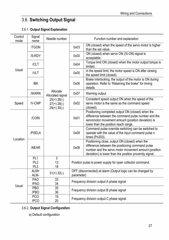
Output Signal Explanation 3.6.1.
Control mode
Signal name
Needle number Function number and explanation
Usual
/TGON
Allocate Allocated signal
25(+) 26(-) 27(+) 28(-) 29(+) 30(-)
0x03 ON (closed) when the speed of the servo motor is higher than the set value.
/S-RDY 0x00 ON (closed) when servo ON (/S-ON) signal is acceptable.
/CLT 0x04 Torque limit ON (closed) when the motor output torque is limited.
/VLT 0x05 In the speed limit, the motor speed is ON after closing the speed limit (closed).
/BK 0x06 Brake interlocking, the output of the motor is ON during operation. Refer to “Retaining the brake” for timing details.
/WARN 0x07 Warning output
Speed /V-CMP 0x02 Consistent speed output ON when the speed of the servo motor is the same as the command speed (closed).
Location
/COIN 0x01
Positioning completed output ON (closed) when the difference between the command pulse number and the servomotor movement amount (position deviation) is lower than the position reach range.
/PSELA 0x09 Command pulse override switching can be switched to operate with the value of the input command pulse n times (Pn203).
/NEAR 0x08
Positioning close, output ON (closed) when the difference between the positioning command pulse number and the servo motor movement amount (position deviation) is lower than the position proximity signal.
PL1 PL2 PL3
3 13 18
Position pulse is power supply for open collector command.
Usual
ALM+ ALM-
31(+) 32(-) OFF (disconnected) at alarm (Output logic can be changed by parameter)
PAO /PAO
33 34
Frequency division output A phase signal
PBO /PBO
35 36
Frequency division output B phase signal
PCO /PCO
19 20
Frequency division output C phase signal
Output Signal Configuration 3.6.2.
a) Default configuration

Wiring and Connections
28
The function of each output signal is configured by the user and is set by parameters Pn613 ~ Pn615. The default functions are as follows:
Function code CN1 pin number Default function
Pn613 25/26 0x00: Servo ready
Pn614 27/28 0x01: Positioning completed
Pn615 29/30 0x02: Consistent speed
b) Negation
1. General switch output signal inversion function, take the servo ready signal (/S-RDY) as an example, default setting Pn613=0x00, servo ready and then the output signal is ON; change the setting Pn613=0x100, the servo is ready, then the output signal is OFF.
2. The alarm output signal (ALM) is the output of the fixed pin number. The default setting is Pn622.1=0. If the servo alarm occurs, the output signal will be OFF. If the change is set to Pn622.1=1, the servo alarm will output the signal ON.
Cautions!
1. Pn622.1 indicates the first bit of parameter Pn622. Refer to function code parameter explanation for details.
2. The signal that is not output is in the "invalid" state. Example speed control, positioning complete (/COIN)
signal is "invalid".
3. If the polarity of the brake signal (/BK) is reversed and used with positive logic, the brake will not be actuated
when the signal line is broken. If you have to use this setting, be sure to check the operation to ensure that there
are no safety issues.
4. When multiple signals are distributed on the same output circuit, the output will be XORed.
Confirming the Output Status 3.6.3.
The status of the output signal can be confirmed by the output signal monitor (Un101). The Un101 segment display and corresponding pin numbers are as follows:
9 8 7 6 5 4 3 2 1
Up:OFFDown:ONCodes
Display LED
The number of input pin Signal name (factory setting)
1 CN1-31、32 ALM
2 CN1-25、26 /S-RDY
3 CN1-27、28 /COIN
Wiring and Connections
29
4 CN1-29、30 /V-CMP
The upper SEG (LED) lights up when the output signal is OFF. The lower SEG (LED) lights up when the output signal is ON.
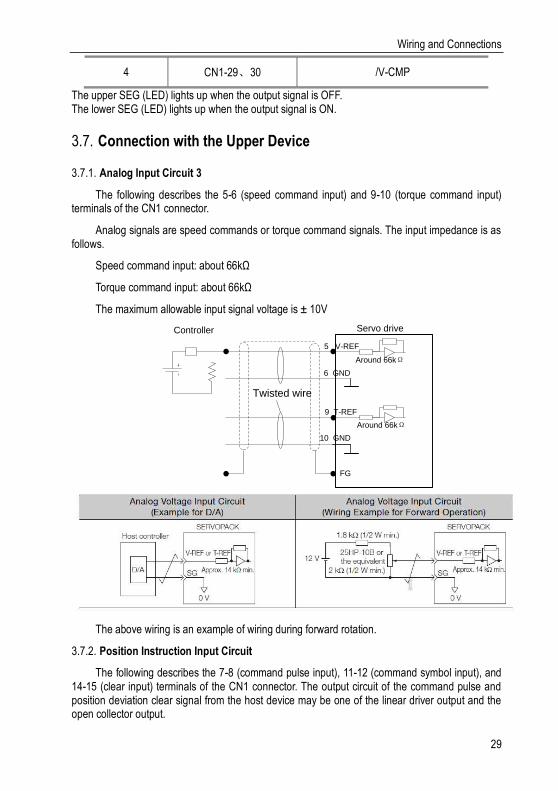
Connection with the Upper Device 3.7.
Analog Input Circuit 3 3.7.1.
The following describes the 5-6 (speed command input) and 9-10 (torque command input) terminals of the CN1 connector.
Analog signals are speed commands or torque command signals. The input impedance is as follows.
Speed command input: about 66kΩ
Torque command input: about 66kΩ
The maximum allowable input signal voltage is ± 10V
5 V-REF
6 GND
9 T-REF
Controller Servo drive
FG
Twisted wire
10 GND
Around 66kΩ
Around 66kΩ
The above wiring is an example of wiring during forward rotation.
Position Instruction Input Circuit 3.7.2.
The following describes the 7-8 (command pulse input), 11-12 (command symbol input), and 14-15 (clear input) terminals of the CN1 connector. The output circuit of the command pulse and position deviation clear signal from the host device may be one of the linear driver output and the open collector output.

Wiring and Connections
30
Connection example of linear drive output
7 PULSE
8 /PULSE
PULSE
SIGN11 SIGN
12 /SIGN
FG
Shield wire
Servo driveHost
computer control
SIGN15 CLR
14 /CLR
150Ω
150Ω
150Ω
The differential pulse input signal voltage is ± 3.3V and the maximum frequency is 4MHz. This signal transmission method has the best anti-noise capability. It is recommended to use this connection preferentially.
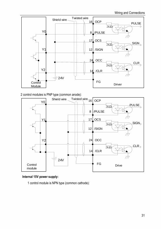
Connection example of open collector outtput 3.7.3.
External 24V power supply:
1 control module is NPN type (common cathode):
Wiring and Connections
31
16 OCP
8 /PULSE
12 /SIGN
FGDriver
Control Module
Y1
Y0
PULSE
SIGN
Twisted wireShield wire
17 OCS
14 /CLR
24V
CLR24 OCC
2KΩ
Y2
2KΩ
2KΩ
2 control modules is PNP type (common anode):
SIGN
FG24V
DriveControl module
Y0
Y1
PULSE
Shield wire Twisted wire
CLR
16 OCP
8 /PULSE
12 /SIGN
17 OCS
14 /CLR
24 OCCY2
2KΩ
2KΩ
2KΩ
Internal 15V power supply:
1 control module is NPN type (common cathode):

Wiring and Connections
32
CLR
GND
Twisted wire
DriveControl module
Y2
Y1
Y0
PULSE7 PULSE
8 /PULSE
11 SIGN
12 /SIGN
15 CLR
14 /CLR
SIGN
3 PL115V
15V13 PL2
15V18 PL3
FG
Shield wire
1KΩ
150Ω
1KΩ
150Ω
1KΩ
150Ω
2 control modules is PNP type (common anode):
Control module
Y0
CLR
FGDrive
PULSE7 PULSE
8 /PULSE
11 SIGN
12 /SIGN
15 CLR
14 /CLR
SIGN
15V3 PL1
15V13 PL2
18 PL315V
1 GND
Y1
Y2
1KΩ
150Ω
1KΩ
150Ω
Twisted wire
Shield wire
1KΩ
150Ω

Wiring and Connections
33
Sequence Control Input Circuit 3.7.4.
The following describes the 38 to 46 terminals of the CN1 port. Connect via a relay or open collector transistor circuit. When using a relay connection, select the relay for the minute current. If you do not use a minute current relay, it will cause poor contact.
E.g., /S-ON
DC24V
SERVOPACK
47 +24VIN
E.g., /S-ON
DC24V
SERVOPACK
47 +24VIN
4.7KΩ4.7KΩ
Examples for Relay Circuit Examples for Open-Collector Circuits
Note: The external power supply (DC24V) must have a capacity of 50 mA or more. The input loop of the servo unit uses a bidirectional optocoupler. Please select the sink
circuit connection or the source circuit connection according to the specifications of the machine.

Wiring and Connections
34
Sequence Output Loop 3.7.5.
Servo unit signal output circuit is the following three kinds:
1. Open collector output circuit
The output signal (SEN, OCZ) is an open collector transistor output circuit. Please receive through optocoupler circuit, relay circuit or linear receiver circuit.

Wiring and Connections
35
OCZ
GND
Twisted wire
Servo drive
Controller
VCC
SEN
OCZ
GND
VCC
SEN
Optocoupler loop example Relay circuit example
Controller
Servo drive
Twisted wire
OCZ
GND
Twisted wire
Servo drive
Controller
VCC
SEN
Linear receiver loop example
2. Optocoupler output circuit
The brake linkage (/BK), servo alarm (ALM), servo ready (/S-RDY) and other sequence output signals belong to the optocoupler output circuit. Connect via relay or line receiver circuit.
ALM/S-RDY and other
output terminals
RY
Servo motor
+
-
Breaker
Enconder
电机
Surge
absorberBrake winding
dedicated
power supply
Emergency
buttonRY
DC24V
/BK
DC24v
Motor
3. Linear drive output circuit
The following describes the 33-34 (phase A signal), 35-36 (phase B signal), and 19-20 (phase C signal) terminals of the CN1 port. The output signal (PAO, /PAO, PBO, /PBO) and the origin pulse signal (PCO, /PCO) of the encoder's serial data are converted into two-phase (A-phase, B-phase) pulses and output through the line driver output circuit. On the upper device

Wiring and Connections
36
side, please use a linear receiver circuit.
PAO
PAO-
PBO
PBO-
PCO
PCO-
GND
Twisted wire
220~
470Ω
Using a linear receiver is
equivalent SN75ALS175
GND
Shelter wire
Servo motor
Please connect shielded
wire according to the
requirements of the
equipment
FG
Wiring and Connections
37
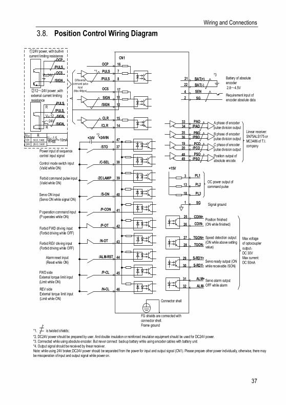
Position Control Wiring Diagram 3.8.
COIN+
COIN-
TGON+
TGON-
S-RDY+
S-RDY-
ALM+
ALM-
PL1
PL2
PL3
SG
PAO/PAO
PBO/PBO
PCO/PCO
/PSOPSO
PULS
/PULS
/SIGN
SIGN
CLR
/CLR
OCP
OCS
Differential
command pulse
input
(Max 4Mpps)
OC
A phase of encoder pulse division output
B phase of encoder pulse division output
C phase of encoder pulse division output
Position output of absolute encode
OC power output of command pulse
Signal ground
Position finished(ON while finished)
Speed detection output(ON while above setting value)
Servo ready output (ON while receivable /SON)
Servo alarm outputOFF while alarm
CN1
7
8
11
12
15
14
Linear receiver:SN75ALS175 or MC3486 of T.I. company
Connector shell
FG shields are connected with connector shell.Frame ground
Max voltage of optocoupler
output:DC 30VMax current: DC 50mA
*1
33
3536
1920
4849
3
34
13
18
1
25
26
27
28
29
30
31
32
�24V power, with built-in
current limiting resistance
12~24V power ,with
external current limiting resistance
VDC24V
PULS
/PULS
SIGN
/SIGN
VDC12
~24V
R
R
VDC
12V
24V
R
2KΩ,1/4W
1KΩ,1/4WVDC-1.5R+68 10mA
OCP
/PULS
OCS
/SIGN
16
17
Battery of absolute encoder
2.8~4.5V
Requirement input of encoder absolute data
*3
4
2
21
22
BAT(+)
BAT(-)
SEN
SG
*2
/S-ON
/P-CON
/P-OT
/N-OT
/ALM-RST
/P-CL
/N-CL
Power input of sequence control input signal
Servo ON input(Servo ON while signal ON)
P operation command input(P operates while ON)
Forbid FWD driving input (Forbid driving while OFF)
Alarm reset input(Reset while ON)
FWD sideExternal torque limit input (Limit while ON)
Forbid REV driving input (Forbid driving while OFF)
REV sideExternal torque limit input (Limit while ON)
40
41
42
43
44
45
46
+24V47
+24VIN
39/ZCLAMP
38/C-SEL
37/STO
Forbid command pulse input(Valid while ON)
Control mode switch input(Valid while ON)
*2. DC24V power should be prepared by user. And double insulation or reinforced insulation equipment should be used for DC24V power. *3. Connected while using absolute encoder. But never connect backup battery while using encoder cables with battery unit. *4. Output signal should be received by linear receiver.Note: while using 24V braker,DC24V power should be separated from the power for input and output signal (CN1). Please prepare other power individually, otherwise, there may be misoperation of input and output signal while power on.
*1. is twisted shields;
+15V

Wiring and Connections
38
Speed Control Wiring Diagram 3.9.
COIN+
COIN-
TGON+
TGON-
S-RDY+
S-RDY-
ALM+
ALM-
PL1
PL2
PL3
SG
PAO/PAO
PBO/PBO
PCO/PCO
/PSOPSO
A phase of encoder pulse division output
B phase of encoder pulse division output
C phase of encoder pulse division output
Position output of absolute encode
OC power output of command pulse
Signal ground
Position finished(ON while finished)
Speed detection output(ON while above setting value)
Servo ready output (ON while receivable /SON)
Servo alarm outputOFF while alarm
CN1
Linear receiver:SN75ALS175 or MC3486 of T.I. company
Connector shell
FG Shields are connected to connector shellFrame grounded
Max voltage of optocoupler
output:DC 30VMax current: DC 50mA
33
3536
1920
4849
3
34
13
18
1
25
26
27
28
29
30
31
32
5
9
10
6
V-REF
SG
SG
T-REF
Speed command input
(Max input voltage:± 10V)D/A
D/A
A/D
External torque limit/ Feedforward torque
(Max input voltage:± 10V)
*2
/S-ON
/P-CON
/P-OT
/N-OT
/ALM-RST
/P-CL
/N-CL
Power input of sequence control input signal
Servo ON Input(Servo ON while signal ON)
P operation command input(P operates while ON)
Forbid FWD driving input(Forbidden while OFF)
Alarm reset input(Reset while on)
FWD sideExternal torque limit input
(Limit while ON)
Forbid REV driving input (Forbidden while OFF)
REV sideExternal torque limit input
(Limit while ON)
40
41
42
43
44
45
46
+24V 47+24VIN
39/ZCLAMP
38/C-SEL
37/STO
Zero-position fixation input(Valid while ON)
Control mode switch input(valid while ON)
Battery of absolute encoder
2.8~4.5V
Requirement input of encoder absolute data
*3
4
2
21
22
BAT(+)
BAT(-)
SEN
SG
*2. DC24V power should be prepared by user. And double insulation or reinforced insulation equipment should be used for DC24V power. *3. Connected while using absolute encoder. But never connect backup battery while using encoder cables with battery unit. *4. Output signal should be received by linear receiver.Note: while using 24V braker,DC24V power should be separated from the power for input and output signal (CN1). Please prepare other power individually, otherwise, there may be misoperation of input and output signal while power on.
*1. is the twisted shields
+15V

Wiring and Connections
39
Torque Control Wiring Diagram 3.10.
COIN+
COIN-
TGON+
TGON-
S-RDY+
S-RDY-
ALM+
ALM-
PL1
PL2
PL3
SG
PAO/PAO
PBO/PBO
PCO/PCO
/PSOPSO
A phase of encoder pulse division output
B phase of encoder pulse division output
C phase of encoder pulse division output
Position output of absolute encode
OC power output of command pulse
Signal ground
Position finished(ON while finished)
Speed detection output(ON while above setting value)
Servo ready output (ON while receivable /SON)
Servo alarm outputOFF while alarm
CN1
Linear receiver:SN75ALS175 or MC3486 of T.I. company
Connector shell
FG Shields are connected to connector shellFrame grounded
Max voltage of optocoupler
output:DC 30VMax current: DC 50mA
33
3536
1920
4849
3
34
13
18
1
25
26
27
28
29
30
31
32
5
9
10
6
V-REF
SG
SG
T-REF
Speed command input
(Max input voltage:± 10V)D/A
D/A
A/D
Torque command input
(Max input voltage:± 10V)
Battery of absolute encoder
2.8~4.5V
Requirement input of encoder absolute data
*3
4
2
21
22
BAT(+)
BAT(-)
SEN
SG
*2
/S-ON
/P-CON
/P-OT
/N-OT
/ALM-RST
/P-CL
/N-CL
Power input of sequence control input signal
Servo ON Input(Servo ON while signal ON)
P operation command input(P operates while ON)
Forbid FWD driving input(Forbidden while OFF)
Alarm reset input(Reset while on)
FWD sideExternal torque limit input
(Limit while ON)
Forbid REV driving input (Forbidden while OFF)
REV sideExternal torque limit input
(Limit while ON)
40
41
42
43
44
45
46
+24V 47+24VIN
39/ZCLAMP
38/C-SEL
37/STO
Zero-position fixation input(Valid while ON)
Control mode switch input(valid while ON)
*2. DC24V power should be prepared by user. And double insulation or reinforced insulation equipments should be used for DC24V power. *3. Connected while using absolute encoder. But never connect backup battery while using encoder cables with battery unit. *4. Output signal should be received by linear receiver.Note: While using 24V braker,DC24V power should be separated from the power for input and output signal (CN1). Please prepare other power individually, otherwise, there may be misoperation of input and output signal while power on.
*1. is the twisted shields
+15V
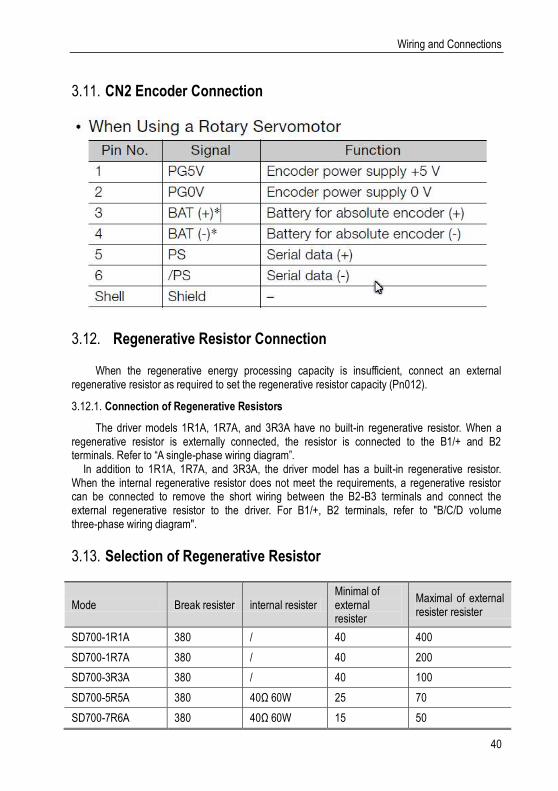
Wiring and Connections
40
CN2 Encoder Connection 3.11.
Regenerative Resistor Connection 3.12.
When the regenerative energy processing capacity is insufficient, connect an external regenerative resistor as required to set the regenerative resistor capacity (Pn012).
Connection of Regenerative Resistors 3.12.1.
The driver models 1R1A, 1R7A, and 3R3A have no built-in regenerative resistor. When a regenerative resistor is externally connected, the resistor is connected to the B1/+ and B2 terminals. Refer to “A single-phase wiring diagram”. In addition to 1R1A, 1R7A, and 3R3A, the driver model has a built-in regenerative resistor. When the internal regenerative resistor does not meet the requirements, a regenerative resistor can be connected to remove the short wiring between the B2-B3 terminals and connect the external regenerative resistor to the driver. For B1/+, B2 terminals, refer to "B/C/D volume three-phase wiring diagram".
Selection of Regenerative Resistor 3.13.
Mode Break resister internal resister Minimal of external resister
Maximal of external resister resister
SD700-1R1A 380 / 40 400
SD700-1R7A 380 / 40 200
SD700-3R3A 380 / 40 100
SD700-5R5A 380 40Ω 60W 25 70
SD700-7R6A 380 40Ω 60W 15 50
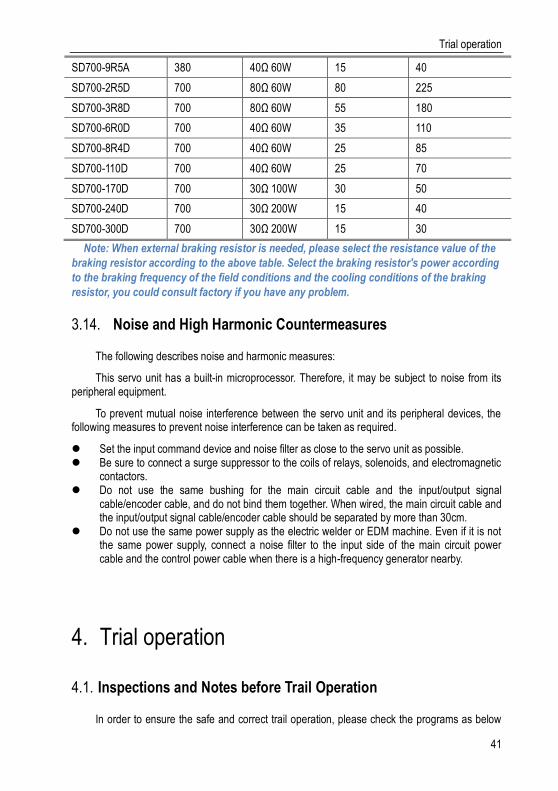
Trial operation
41
SD700-9R5A 380 40Ω 60W 15 40
SD700-2R5D 700 80Ω 60W 80 225
SD700-3R8D 700 80Ω 60W 55 180
SD700-6R0D 700 40Ω 60W 35 110
SD700-8R4D 700 40Ω 60W 25 85
SD700-110D 700 40Ω 60W 25 70
SD700-170D 700 30Ω 100W 30 50
SD700-240D 700 30Ω 200W 15 40
SD700-300D 700 30Ω 200W 15 30
Note: When external braking resistor is needed, please select the resistance value of the
braking resistor according to the above table. Select the braking resistor's power according
to the braking frequency of the field conditions and the cooling conditions of the braking
resistor, you could consult factory if you have any problem.
Noise and High Harmonic Countermeasures 3.14.
The following describes noise and harmonic measures:
This servo unit has a built-in microprocessor. Therefore, it may be subject to noise from its peripheral equipment.
To prevent mutual noise interference between the servo unit and its peripheral devices, the following measures to prevent noise interference can be taken as required.
Set the input command device and noise filter as close to the servo unit as possible. Be sure to connect a surge suppressor to the coils of relays, solenoids, and electromagnetic
contactors. Do not use the same bushing for the main circuit cable and the input/output signal
cable/encoder cable, and do not bind them together. When wired, the main circuit cable and the input/output signal cable/encoder cable should be separated by more than 30cm.
Do not use the same power supply as the electric welder or EDM machine. Even if it is not the same power supply, connect a noise filter to the input side of the main circuit power cable and the control power cable when there is a high-frequency generator nearby.
Trial operation 4.
Inspections and Notes before Trail Operation 4.1.
In order to ensure the safe and correct trail operation, please check the programs as below

Trial operation
42
before that:
Conditions of the Servo Motor: 4.1.1.
You need to check and confirm all programs as below, if there is any problem, please handle it properly before that trail operation
1. Are the Settings, wires and connections correct?
2. Is there any looseness in each fastening part?
3. When you use servo motors with oil seals, is the oil seal damaged? Is it smeared with organic oil?
4. Is the brake released beforehand when it is a servo motor with a holding brake?
Conditions of the Servo Drive 4.1.2.
You need to check and confirm all programs as below, if there is any problem, please handle it properly before that trail operation.
1. Are the Settings, wires and connections correct?
2. Is the supply voltage of the servo unit normal?
3. Is the driver status display interface free of warnings, alarms, etc.?
Installation 4.1.3.
1. Install the servo motor and servo unit according to the installation conditions.
2. The servo motor may fall when it rotates, so be sure to fix it on the machine.
3. Be sure to leave the servomotor at no load.
JOG trail operation 4.2.
The trial run refers to the JOG operation of the servo motor unit. The purpose of the single trial operation of the servo motor is to confirm whether the servo unit and the servo motor are correctly connected and whether the servo motor is operating normally. Confirm the following points before running:
The motor is in the enabled state and the jog operation is invalid during the operation.We suggest that the load inertia is not greater than thirty times of the motor inertia, or it could possibly cause strong mechanical vibration.
The Pn500, Pn310, Pn311 parameters set JOG speed, acceleration and deceleration time.For details on the panel operation steps, see "Auxiliary Functions".

Operation
43
Operation 5.
Basic Functions 5.1.
Quick Guide 5.1.1.
Basic parameters quick guide
Servo-enabled, Over-travelSetting parameters Pn601~Pn609
For wiring details, see "Sequence input circuit"
Stop modesSetting parameters Pn004/Pn005/Pn007
Electromagnetic brakeSetting parameters Pn008/
Pn009/Pn010For wiring details, see "Sequence output circuit"
Regeneration resistanceSetting parameters Pn012/Pn013For connection details, see
"Regeneration Resistor Connection"
OverloadSetting parameters
Pn015/Pn016
Torque limitSetting parameters Pn050~Pn052Set parameters Pn045~Pn047
(undervoltage)
Motor rotation direction
Setting parameter Pn002
Servo Enable and Over-range Setting 5.1.2.
Enable
Set the servo ON (/S-ON) signal that controls servo motor electrification / non- electrification. Pin numbers can be configured by parameters Pn601 ~ Pn609, and are always configured effectively by parameters Pn610~Pn612. See “Input Signal Configuration” for details.
Over-range
The over-range prevention function of the servo unit refers to the safety function of forcibly stopping the servo motor by inputting a signal of the limit switch when the movement part of the machine exceeds the safe movement range. For rotary applications such as circular tables and conveyors, the over-range function may not be required. In this case, the input signal wiring for over-range is not required.
Cautions! 1. In the one-way over-travel state, commands in the opposite direction of over-travel can
be received.2. In position control, when the servo motor stops due to over - travel, the position deviation remains unchanged. To clear the position deviation, a clear signal (CLR) must be input.
1. Signal Setting
Pin numbers can be configured by parameters Pn601~Pn609, and are always configured effectively by parameters Pn610~Pn612. See “Input Signal Configuration” for details.
2. Stop Mode
When an over-range occurs, the servo motor can be stopped by any of the following three methods.

Operation
44
Dynamic brake (DB) stop: By short-circuiting the electrical circuit, the servo motor can be quickly stopped.
Deceleration stop: Decelerate to stop with the emergency stop torque (Pn053). Free-running stop: Naturally stopped due to friction when the motor rotates.
The servo motor status after stopping is divided into the following two types.
Free running state: A state that naturally stops due to friction when the motor rotates.
Zero-fixed state: The state of the zero position is maintained in the position loop.
When the over-range occurs, select the stopping method of the servo motor through Pn007. For details, please see parameter Pn007.
Cautions! It cannot decelerate to stop during torque control. Pn007 is set to DB or
free-running stop. After the servo motor stops, it enters the free running state.
3. Warning Checkout
The over-range warning function is a function that detects the over-range warning (A.9A0) after the over-range is entered when the servo is turned on. With this function, the servo unit can transmit the information on detecting the over-range to the upper device even if the over-range signal is input instantaneously. When using this function, please set Pn006=1 "Check over-range warning".
The timing of check out over-travel warning
OFF ON
Overtravel signal
Invalid Valid Invalid
Overtravel warningAL9A0
正常 Warning status lasts 1s
Normal
Enable OFF does not check out warningAutomatically clear warnings
Valid Invalid
A warning is detected when an over-range occurs in the same direction as the command.
When an over-range in the opposite direction to the command is issued, no warning is detected. For example, under the forward command, no warning will be issued even if the N-OT signal (reverse drive prohibited) is turned on while moving.
When there is no instruction, an over-range warning in the forward or reverse direction will be detected.

Operation
45
When the servo is turned off, no warning will be detected even if it enters the over-range state.
In the over-range state, no warning is detected when the servo is switched from the servo OFF state to the servo ON state. The warning I/O will remain output for 1 second after the over-range status is released and will be automatically cleared afterwards.
Motor Rotation Direction 5.1.3.
The actual rotation direction of the servo motor can be switched by Pn002 without changing the polarity of the speed command/position command. At this time, although the rotation direction of the motor is changed, the polarity of the output signal from the servo unit, such as the encoder frequency-divided pulse output, does not change.
Pn002=0 in the factory setting (forward rotation direction) indicates that the counterclockwise rotation (CCW) is positive when looking at the servo motor cover.
Function mode
Parameter name
Range Defaults Unit Communication
address When enabled
Pn002
Motor rotation direction selection
0~1 0 - 0x0002 After restart
Faces to the motor end: 0- Counterclockwise direction is positive 1- Clockwise direction is positive
Stop Mode 5.1.4.
1. Servo OFF and class 1 alarms
Motor stop method can be selected by Pn004
• Dynamic brake (DB) stops and maintains DB status: By shorting the electrical circuit, the servo motor can be stopped in an emergency, and the DB status is maintained after stopping.
• Dynamic brake (DB) stops and DB status is released: By shorting the electrical circuit, the servo motor can be stopped in an emergency and the DB status is released after stopping.
• Free running stop: The friction when the motor rotates naturally stops.
Cautions! When the servo motor stops or rotates at a very low speed, when the dynamic brake is selected to stop, it will
be the same as the free stop, and no braking force will be generated.
2. Topping modes for type 2 alarms
Type 2 alarms can select zero speed stop in addition to the servo motor OFF method and type 1 alarm stop method. See the description of parameter Pn053 for the torque limit at zero speed stop.

Operation
46
Cautions! The setting of zero speed stop mode is valid only for position control and speed control.
Electromagnetic Brake 5.1.5.
The brake is a part that holds the position when the servo unit power is off so that the moving part of the machine does not move due to its own weight or external force. It is built into the servo motor with a brake. Please use it as shown below.
The brake has a delay time for operation. ON and OFF of the operation ensure the brake operation time.
Servo enable signal(/S-
ON)
Motor power
Brake linkage signal(/BK)
Electromagnetic brake status
OFF ON OFF
OFF
OFF OFF
OFFON
ON
Brake openBrake holding brake
Brake holding brake
Position, speed
instruction
OFFON
OFF
1
3
1
2
OFF
1. Different types of brakes may have slightly different holding brakes and loosening brakes.
2. Please ensure that the input command is after the brake opening operation time to ensure the accuracy of the command

Operation
47
3. When the motor is locked, it may cause danger when the servo motor is prevented from operating when the servo is turned off. The motor lock time (Pn008) can be set to ensure that the motor during the brake is not operated.
The motor stops locking/BK signal OFF timing
When an alarm occurs during servo motor rotation, the servo motor stops and the brake signal (/BK) turns OFF. At this time, the brake signal (/BK) output time can be adjusted by setting the brake command output speed value (Pn010) and the servo OFF-brake command waiting time (Pn009), the brake signal (/BK) output time can be adjusted.
Servo enable signal(/S-
ON)
Motor power
Brake linkage signal(/BK)
ON OFF
Motor is not powered
OFFON
Motor power
Feedback speed
1
2
Brake delay release speedPn010
Brake delayPn009
When the motor enters the non-energized state, when the motor speed is lower than the set value of Pn010, the /BK signal output time is subject to 1
After the motor enters the non-energized state, the set time of Pn009 is passed first, and the output time of /BK signal is subject to 2
The motor is running / BK signal OFF timing
When the servo motor is stopped, the brake (/BK) signal and the servo ON (/S-ON) signal are turned off at the same time. By setting Pn008, it is possible to change the time from when the servo ON (/S-ON) signal is OFF to when the motor actually enters the non-energized state.
Servo enable signal(/S-ON)
Motor energized
Brake chain signal(/BK)
ON OFF
Brake
The motor is not powered
Motor energized
Brake open
Pn008
Note:
An alarm occurs when the servo is locked. Regardless of this setting, the servo motor immediately enters the non-energized state.

Operation
48
At this time, the machine may move before the brake due to the delay of the brake action.
Regenerative Resistor 5.1.6.
Refer to “Regeneration Resistor Connection” for the wiring method. When connecting an external regenerative resistor, set parameters Pn012 and Pn013 according to the external resistance.
The regenerative resistor capacity should be set to a value that matches the allowable capacity of the connected external regenerative resistor. The setting differs depending on the cooling condition of the external regenerative resistor.
• Self-cooling method (natural convection cooling): Set to 20% or less of the regenerative resistor capacity (W).
• Forced air cooling: Set to 50% or less of the regenerative resistor capacity (W).
Example: When the capacity of the self-cooling external regenerative resistor is 100W, the setting value is 100W × 20% = 20W. Therefore, set Pn012 = 2 (setting unit: 10W).
Overload 5.1.7.
This servopack can change the detection time of the overload warning (AL.910) and overload (continuous maximum) alarm (Er. 720). However, it is not possible to change the detection value of the overload characteristic and overload (instantaneous maximum) alarm (Er. 710). The factory defaults are:
1. Change of the time of detection of overload warning (AL.910)
The factory overload warning detection time is 20% of the overload alarm detection time. The overload warning detection time can be changed by changing the overload warning value (Pn015). In addition, using it as an overload protection function corresponding to the system used can improve the security of the system. For example, as shown below, after changing the overload warning value (Pn015) from 20% to 50%, the overload warning detection time is half (50%) of the overload alarm detection time.
Overload detection
time
Torque command%100% 200%
Overload alarm detection curve
50% overload warning
detected
20% overload warning detected
2. Change of the detection time of the overload warning (Er. 720)
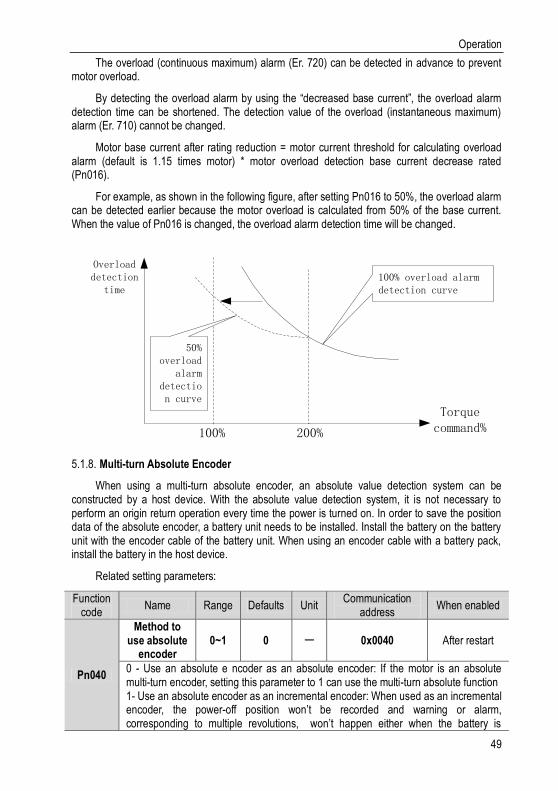
Operation
49
The overload (continuous maximum) alarm (Er. 720) can be detected in advance to prevent motor overload.
By detecting the overload alarm by using the “decreased base current”, the overload alarm detection time can be shortened. The detection value of the overload (instantaneous maximum) alarm (Er. 710) cannot be changed.
Motor base current after rating reduction = motor current threshold for calculating overload alarm (default is 1.15 times motor) * motor overload detection base current decrease rated (Pn016).
For example, as shown in the following figure, after setting Pn016 to 50%, the overload alarm can be detected earlier because the motor overload is calculated from 50% of the base current. When the value of Pn016 is changed, the overload alarm detection time will be changed.
Overload detection
time
Torque command%100% 200%
100% overload alarm detection curve
50% overload
alarm detection curve
Multi-turn Absolute Encoder 5.1.8.
When using a multi-turn absolute encoder, an absolute value detection system can be constructed by a host device. With the absolute value detection system, it is not necessary to perform an origin return operation every time the power is turned on. In order to save the position data of the absolute encoder, a battery unit needs to be installed. Install the battery on the battery unit with the encoder cable of the battery unit. When using an encoder cable with a battery pack, install the battery in the host device.
Related setting parameters:
Function code
Name Range Defaults Unit Communication
address When enabled
Pn040
Method to use absolute
encoder 0~1 0 - 0x0040 After restart
0 - Use an absolute e ncoder as an absolute encoder: If the motor is an absolute multi-turn encoder, setting this parameter to 1 can use the multi-turn absolute function 1- Use an absolute encoder as an incremental encoder: When used as an incremental encoder, the power-off position won’t be recorded and warning or alarm, corresponding to multiple revolutions, won’t happen either when the battery is

Operation
50
under-voltage or the drive is de-energized
Pn041
Absolute encoder battery
warning/warning
selection
0~1 0 - 0x0041 After restart
0- Set the low battery voltage as a fault: The driver powers up/resets for 4~9 seconds to monitor the battery status. Under-voltage will be reported as an under voltage alarm (Er. 830). Over time will not be detected. 1- Set the low battery voltage as a warning: Under-voltage (below 3V) will be reported as an under voltage alarm (Al.930). It will always monitor the battery voltage and can be self-recovery meanwhile enable running is out of restriction.
Pn792
Absolute encoder operation
0~2 0 - 0x0792 After restart
0 - No action 1- Write motor parameters to encoder EEPROM 2- Clear multi-turn encoder laps: if you use it initially or replace or insert/remove the battery during power-down of the drive. After power on, an encoder backup alarm (Er. 810) will be reported. This parameter is set to 2 and it can only be cleared after re-powered.
Related monitoring data:
Monitoring code
Monitoring name Range Unit Communication
address
Un010
Absolute encoder single-turn value
0x80000000~0x7fffffff
Encoder pulse unit
0xE011
Displays the single-turn absolute position of the servo motor rotor's current position
Un011
Absolute encoder multi-turn value
0x80000000~0x7fffffff
Encoder pulse unit
0xE011
Displays the single-turn absolute position of the servo motor rotor's current position.
Cautions! 1. When replacing the battery, please make sure that the driver is powered on and the
encoder cable is connected normally. Otherwise, the encoder will be notified of the backup
warning by reconnecting the encoder.
Torque Limit 5.1.9.
1. Torque limit method
For the purpose of protecting the machine etc., the output torque can be limited and set by parameter Pn050. The torque limit can be in the following four ways:
Pn050 Torque limit method description Related parameters
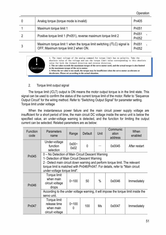
Operation
51
0 Analog torque (torque mode is invalid) Pn405
1 Maximum torque limit 1 Pn051
2 Positive torque limit 1 (Pn051), reverse maximum torque limit 2 Pn051 、Pn052
3 Maximum torque limit 1 when the torque limit switching (/TLC) signal is OFF; Maximum torque limit 2 when ON.
Pn051 、Pn052
Cautions!
1. The input voltage of the analog command for torque limit has no polarity. Take the absolute value of the voltage and use the torque limit value corresponding to this absolute value for both the forward direction and reverse direction.2. The set value exceeds the maximum torque of the servo motor used, and the actual torque is also limited
to the maximum torque of the servo motor.
3. When the set value is too small, the torque may be insufficient when the servo motor accelerates or
decelerates. Please set according to the actual situation.
2. Torque limit output signal
The torque limit (/CLT) output is ON means the motor output torque is in the limit state. This signal can be used to confirm the status of the current torque limit of the motor. Refer to “Sequence Output Circuit” for the wiring method. Refer to “Switching Output Signal” for parameter setting. Torque limit under voltage
When the instantaneous power failure and the main circuit power supply voltage are insufficient for a short period of time, the main circuit DC voltage inside the servo unit is below the specified value, an under-voltage warning is detected, and the function for limiting the output current can be selected. Related parameters are as below:
Function code
Parameters name
Range Default Unit Communic
ation address
When enabled
Pn045
Under-voltage function selection
0x00~0x02
0 - 0x0045 After restart
0 – No Detection of Main Circuit Descent Warning 1- Detection of Main Circuit Descent Warning 2 - Detect main circuit down warning and perform torque limit. The relevant torque limit is matched with Pn046/Pn047. For details, refer to "Main circuit under-voltage torque limit".
Pn046
Torque limit when main
circuit voltage drops
0~100 50 % 0x0046 Immediately
According to the under voltage warning, it will impose the torque limit inside the servo unit.
Pn047
Torque limit release time when main
circuit voltage
0~1000
100 Ms 0x0047 Immediately

Operation
52
drops
After the under-voltage warning signal releases, the torque limit value is controlled within the servo unit according to the set time. For details, see "Under-voltage limit of the main circuit".
By combining this function with the setting function of the instantaneous stop holding time, when the power supply voltage is insufficient, it is possible to avoid the shutdown due to the alarm and continue the operation without performing the power restoration operation.
Uner-voltage warning, apply torque limit inside the servo unit. After receiving the under voltage warning release signal, the torque limit value is controlled within the servo unit according to the set release time. The logical timing is as follows:
Main loop input power
Main circuit power disconnection time
bus voltage
280V *1
200V*2
0% Torque
Torque limit
Undervoltage warning Starting
torque limit
Pn046
Pn047
The bus voltage drop speed can be alleviated by limiting the output torque
1: 560V at 400VAC2: 400V at 400VAC
Position Mode 5.2.
For details on the wiring related to the position mode; see "Connection Control Example for Position Control". The position control is selected by the control mode selection (Pn000 = 0, factory default).
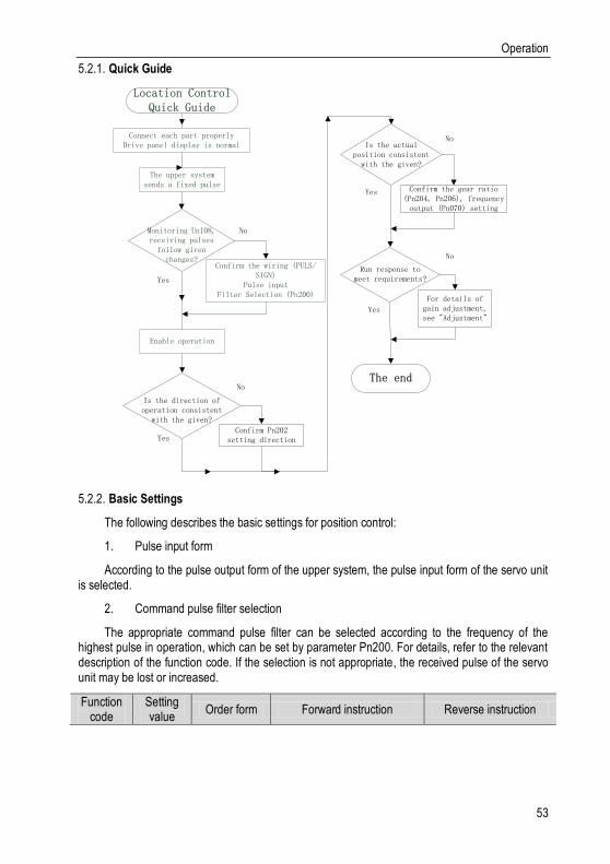
Operation
53
Quick Guide 5.2.1.
Enable operation
Monitoring Un108, receiving pulses
follow given changes?
Connect each part properlyDrive panel display is normal
The upper system sends a fixed pulse
Confirm the wiring (PULS/SIGN)
Pulse inputFilter Selection (Pn200)
No
Yes
Is the direction of operation consistent
with the given?
Confirm Pn202 setting directionYes
No
Is the actual position consistent
with the given?
Confirm the gear ratio (Pn204, Pn206), frequency output (Pn070) setting
Yes
No
Run response to meet requirements?
For details of gain adjustment, see "Adjustment"
No
Yes
The end
Location Control Quick Guide
Basic Settings 5.2.2.
The following describes the basic settings for position control:
1. Pulse input form
According to the pulse output form of the upper system, the pulse input form of the servo unit is selected.
2. Command pulse filter selection
The appropriate command pulse filter can be selected according to the frequency of the highest pulse in operation, which can be set by parameter Pn200. For details, refer to the relevant description of the function code. If the selection is not appropriate, the received pulse of the servo unit may be lost or increased.
Function code
Setting value
Order form Forward instruction Reverse instruction

Operation
54
Pn201
0 Pulse + direction
positive logic
1 CW+CCW
positive logic
4 Quadrature encoding 4
times
5
Pulse + direction negative
logic
6 CW+CCW negative
logic
3. Electronic gear ratio
When the reduction ratio of the motor shaft and the load side is n/m (when the load shaft rotates by n revolutions when the motor rotates by m revolutions), the set value of the electronic gear ratio can be obtained by the following formula:
Electronic gear ratio𝐵
𝐴=
𝑃𝑛204
𝑃𝑛206
=Encoder resolution
Load shaft movement amount in 1 rotation (command unit)×
𝑚
𝑛
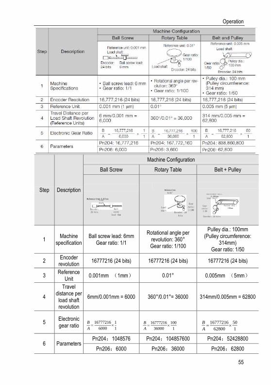
Operation
55
Step Description
Machine Configuration
Ball Screw Rotary Table Belt + Pulley
1 Machine
specification Ball screw lead: 6mm
Gear ratio: 1/1
Rotational angle per revolution: 360° Gear ratio: 1/100
Pulley dia.: 100mm (Pulley circumference:
314mm) Gear ratio: 1/50
2 Encoder
revolution 16777216 (24 bits) 16777216 (24 bits) 16777216 (24 bits)
3 Reference
Unit 0.001mm (1mm) 0.01° 0.005mm (5mm)
4
Travel distance per load shaft revolution
6mm/0.001mm = 6000 360° /0.01° = 36000 314mm/0.005mm = 62800
5 Electronic gear ratio
6 Parameters Pn204:1048576 Pn204:104857600 Pn204:52428800
Pn206:6000 Pn206:36000 Pn206:62800
Encoder: 24 bits
Ball screw
lead: 6mm
Reference Unit: 0.001mmLoad shaft Gear
ratio: 1:100
Load shaft
Reference Unit:
0.01°
Encoder: 24 bits
Gear ratio: 1:50
Pulley dia.: 100mm
Load Shaft
Reference Unit: 0.005mm
Encoder: 24 bits
16777216 1
6000 1
B
A
16777216 100
36000 1
B
A
16777216 50
62800 1
B
A

Operation
56
Cautions! 1. When the electronic gear ratio numerator is 0, the denominator setting is the number of
command pulses corresponding to one revolution of the motor.2. If 0.001 ≤ electronic gear ratio (B/A) ≤ 16778 is out of this setting range, "Er. 040 alarm" will occur.
Deviation Clearance 5.2.3.
The deviation clear signal (/CLR) is the input signal to clear the servo unit deviation counter.
1. Clear signal wiring
Deviation clear signal wiring can be divided into linear driver output and open collector output. Please refer to “Position Command Input Circuit” for wiring details.
2. Setting the deviation clear mode
The shape of the clear signal is set by Pn272.
function code
parameter name range Defaults unit mailing address
Effective mode
Pn272
Position deviation clear mode
0x00~0x03 0 - 0x0272 Power down
effective
Set the clear mode of the digital position deviation clear signal (/CLR): 0-level clear when cleared 1-rising edge OFF->ON clear Clear when 2-level OFF 3-falling edge clears when ON->OFF
When Pn272 = 0 or 2, in order to perform clear signal processing, the amplitude of the clear signal must be 250μs or more.
When Pn272 = 1 or 3, in order to perform clear signal processing, the amplitude of the clear signal must be 20μs or more.
About the pulse amplitude of the clear signal
When Pn272 = 0 or 2, the clear signal must have a width of 250 μs or more in order to perform clear signal processing.
When Pn272 = 1, 3, the clear signal amplitude must be 20 μs or more in order to perform clear signal processing.
Cautions! When set to keep clear, the servo lock function is invalid. Therefore,
the servo motor will rotate at a slight speed due to the drift pulse in
the speed loop.
3. Deviation clearing method selection

Operation
57
Depending on the status of the servo unit, you can choose when to clear the position deviation. Set the deviation clearing method by Pn273:
function code
parameter name range Default
s unit
mailing address
Effective mode
Pn273
Position deviation clear mode
0x00~0x02 0 - 0x0273 Power down
effective
Set the clear mode of the digital position deviation clear signal (/CLR): 0-level clear when cleared 1-rising edge OFF->ON clear Clear when 2-level OFF 3-falling edge clears when ON->OFF
See the “Deviation Clearance” for details on the pulse amplitude of the clear signal.
In position control, the positional deviation remains unchanged when the servo motor is stopped due to the travel limit.
Cautins! When the position mode is running, the servo motor stops running due to
the stroke limit, and the position deviation is still maintained. Pay
attention to the safety of the motor when removing the stroke limit.
Command Pulse Prohibition 5.2.4.
The command pulse inhibition (/INHIBIT) function is a function that prohibits the command pulse input from being counted during position control. When this function is enabled, the servo unit enters a state where it cannot receive the command pulse input.
1. Configuration of Command Pulse Prohibition
The signal is not configured in the factory default switch configuration. Therefore, the pin number configuration (0x0D) needs to be performed by parameters Pn601~Pn609.
2. Command pulse inhibited wiring
The command pulse disable signal is a universally configurable digital input. See "Sequence Input Circuit" for wiring details.
Positioning Approach 5.2.5.
When positioning is close to (/NEAR) position control, the host device may receive the positioning proximity signal before confirming the positioning completion signal, so as to prepare for the sequence of actions after the positioning is completed. In this way, the time required to complete the positioning can be shortened. This signal is usually used in pair with the positioning completion signal. Refer to the “Positioning completed” instruction for the positioning completion signal.
1. Positioning close to the configuration
The signal is not configured in the factory default digital output configuration. Therefore, the

Operation
58
pin number configuration (0x08) needs to be performed by parameters Pn613~Pn615.
When the difference between the command pulse number of the host device and the movement amount of the servo motor (position deviation) is lower than the setting value of Pn260 (position proximity signal width), the signal is output when the positioning close output condition is satisfied.
2. Locating close wiring
The positioning proximity signal is a universally configurable digital output. See “Sequence Output Circuit” for wiring details
Positioning Completion 5.2.6.
In position control, it indicates the servo motor positioning completed (/COIN) signal.
1. Positioning completed configuration
In the factory default digital output configuration, the signal is configured as CN1's 27th and 28th pin numbers (Pn614=0x01) by default. Please confirm before use.
Function code
Parameter name
Range Defaults Unit Communication
address When enabled
Pn262
Positioning completion
range 0~1073741824 7
Command unit
0x0262 0x0263
Immediately
In the position control, the servo motor positioning completion signal will be output when the difference between the command pulse number from the host device and the servo motor movement amount (position deviation) is lower than the set value that means the host device confirming positioning has been completed.
If the set value is too large, the permanent positioning completion signal may be output when the deviation is small during low-speed operation. When outputting a constant positioning signal, please lower the setting until the signal is no longer output.
Function code
Parameter name
Range def
aults u
nit
Communication address
When enabled
Pn274
Positioning completion
signal output time
0x00~0x02 0 - 0x0274 Immedi
ately
Set the output timing of the positioning completion signal /COIN: 0- Output when the absolute value of position deviation is less than the positioning
completion range (Pn262). 1- Output when the absolute value of the position deviation is smaller than the
positioning completion range (Pn262) and the command after the position command filtering is 0.
2- Output When the absolute value of the position deviation is smaller than the positioning completion range (Pn262) and the positioning command input is 0.
2. Positioning completion wiring
The positioning completion signal is a universally configurable digital output. For wiring details, refer to “Sequence Output Circuit”.

Operation
59
Command Pulse Input Magnification Switching 5.2.7.
The ON/OFF of the override input switching signal (/PSEL) of the command pulse input switches the input override of the position command pulse to 1 and n times (n = 1 to 100). The switching of the override can be confirmed by the command pulse input of the override switching output signal (/PSELA).
Please switch the command pulse magnification while the position command pulse is 0. If the position command pulse is not 0, the servo motor may cause a position error or cause a position loss.
1. Configuration of command pulse input magnification switching
The signal is not configured in the factory default digital input configuration. Therefore, the pin number configuration (0x10) needs to be performed by parameters Pn601~Pn609.
Command pulse input magnification Pn203
Function code
Parameter name
Range defaults unit Communication
address When enabled
Pn203
Command pulse input
magnification 1~100 1
x1 times
0x0203 Immediately
Set the command pulse input magnification value to be used in conjunction with ON/OFF of the command pulse magnification switching signal for switching the position command pulse input magnification to 1 and the parameter setting multiple. Note: The input pulse frequency is too low. If the value is set too large, the speed may not be steady.

Operation
60
Command pulse input multiplier switching input signal /PSEL
Command pulse input multiplier switching output signal /PSELA
Valid
Invalid
Valid
Invalid
Below 4ms
x1 Pn203 x1
Below 4ms
Internal action
2. Command pulse input magnification switching wiring
The command pulse input override signal is a universally configurable digital input. See “Sequence Input Circuit” for wiring details.
Smooth Settings 5.2.8.
The command pulse input is filtered to make the rotation of the servo motor smoother. This function is more effective in the following situations:
The host device that issued the command does not perform acceleration / deceleration
When the instruction pulse frequency is extremely low
When the position command smoothing function is set, the system response may be affected. Please use it reasonably.
The filter-related parameter settings are as follows:
Function code
Parameter name
Range defaults unit Communic
ation address
When enabled
Pn211
Position command
low-pass filter time constant
0~655 0 ms 0x0211 After stop
This parameter is used to set the time constant of the first-order low-pass filter corresponding to the position command and it can reduce the mechanical shock in the case of abrupt changes in the input pulse command frequency by setting this parameter.
Pn212
Average filter time in position
instruction rolling
0~1000 0 ms 0x0212 After stop
This parameter is used to set the time constant of the moving average filter of the corresponding position instruction. It can reduce the mechanical shock in the case of abrupt changes in the input pulse command frequency by setting this parameter.
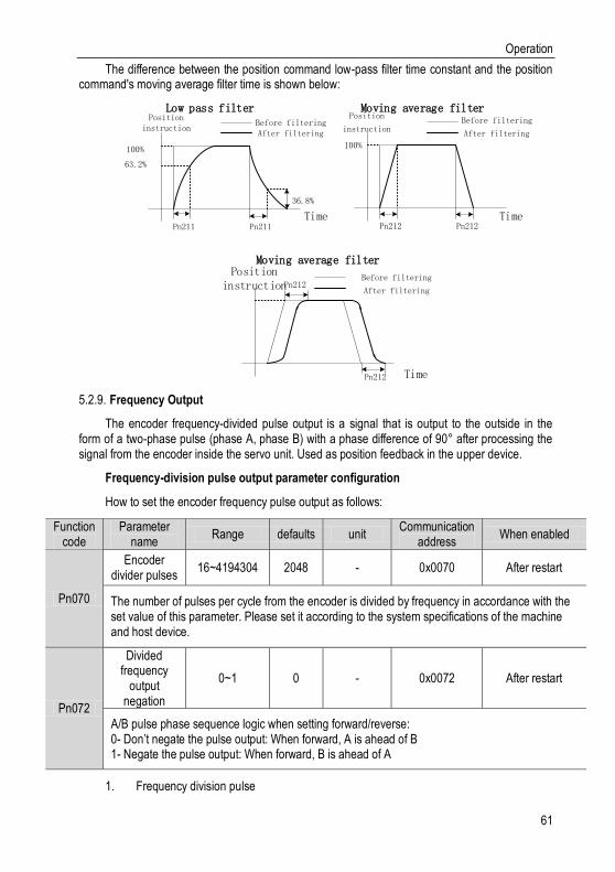
Operation
61
The difference between the position command low-pass filter time constant and the position command's moving average filter time is shown below:
Position instruction
100%
63.2%
36.8%
Pn211 Pn211
Before filteringAfter filtering
Time
Low pass filter Moving average filterPosition
instruction
Pn212 Pn212
Before filtering
After filtering
Time
100%
Moving average filter
Pn212
Pn212
Before filtering
After filtering
Position instruction
Time
Frequency Output 5.2.9.
The encoder frequency-divided pulse output is a signal that is output to the outside in the form of a two-phase pulse (phase A, phase B) with a phase difference of 90° after processing the signal from the encoder inside the servo unit. Used as position feedback in the upper device.
Frequency-division pulse output parameter configuration
How to set the encoder frequency pulse output as follows:
Function code
Parameter name
Range defaults unit Communication
address When enabled
Pn070
Encoder divider pulses
16~4194304 2048 - 0x0070 After restart
The number of pulses per cycle from the encoder is divided by frequency in accordance with the set value of this parameter. Please set it according to the system specifications of the machine and host device.
Pn072
Divided frequency
output negation
0~1 0 - 0x0072 After restart
A/B pulse phase sequence logic when setting forward/reverse: 0- Don’t negate the pulse output: When forward, A is ahead of B 1- Negate the pulse output: When forward, B is ahead of A
1. Frequency division pulse
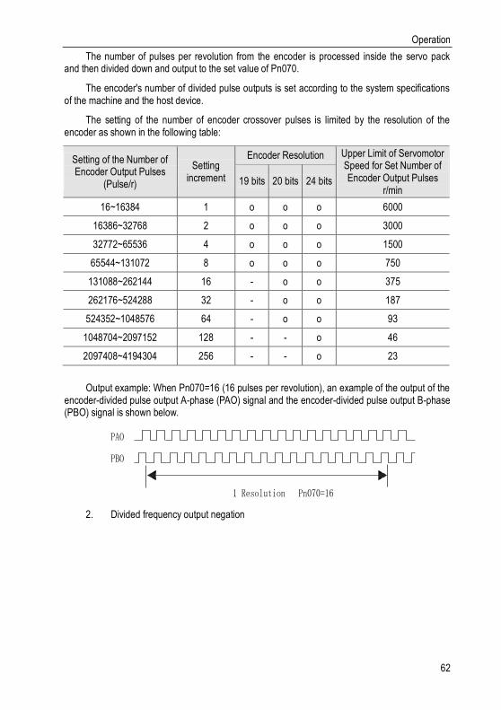
Operation
62
The number of pulses per revolution from the encoder is processed inside the servo pack and then divided down and output to the set value of Pn070.
The encoder's number of divided pulse outputs is set according to the system specifications of the machine and the host device.
The setting of the number of encoder crossover pulses is limited by the resolution of the encoder as shown in the following table:
Setting of the Number of Encoder Output Pulses
(Pulse/r)
Setting increment
Encoder Resolution Upper Limit of Servomotor Speed for Set Number of Encoder Output Pulses
r/min 19 bits 20 bits 24 bits
16~16384 1 o o o 6000
16386~32768 2 o o o 3000
32772~65536 4 o o o 1500
65544~131072 8 o o o 750
131088~262144 16 - o o 375
262176~524288 32 - o o 187
524352~1048576 64 - o o 93
1048704~2097152 128 - - o 46
2097408~4194304 256 - - o 23
Output example: When Pn070=16 (16 pulses per revolution), an example of the output of the encoder-divided pulse output A-phase (PAO) signal and the encoder-divided pulse output B-phase (PBO) signal is shown below.
PAO
PBO
1 Resolution Pn070=16
2. Divided frequency output negation

Operation
63
90°
When forward, B phase leads 90°
90°
When reversing, phase A leads 90°
A
B
C
Time Time
A
B
C
Parameter Pn072 can be set to invert the logic of the AB phase signal of the divided output pulse.
The amplitude of the Z-phase pulse varies with the number of encoder-divided pulses (Pn070) and is consistent with the amplitude of the A-phase.
Split pulse output wiring
See the “Linear Drive Output Circuit” for details on the wiring of the divided pulse output.
Speed Mode 5.3.
For details on speed mode wiring, see "Speed Control Connection Example". It is selected by control mode selection (Pn000).
The speed control mode is divided into internal speed mode (Pn000=3) and analog speed mode (Pn000=1) according to the command source.

Operation
64
Quick Guide 5.3.1.
Enable operation
Monitoring Un103, receiving speed follows
given changes?
Connect each part properlyDrive panel display is normal
The upper system gives a fixed voltage V-REF
Confirm the wiring (V-REF)
See "Analog Input Circuit" for details
No
Yes
Is the direction of operation consistent with
the given?
Confirm Pn301 setting direction.Yes
No
Is the actual speed consistent with the
given?
Confirm analog speed command gain
setting Pn300, Pn302, Pn303
Yes
No
Run response to meet requirements?
Gain adjustment, see "Adjustment"
for details.
No
Yes
The quick wizard ends
Speed Control Quick Guide
The upper system gives a binary signal (/SPD-A, /SPD-B, /SPD-D)
Select internal speed (Pn304, Pn305, Pn306)
Internal speed control (Pn000=3)
Analog speed control (Pn000=1)
Basic Settings 5.3.2.
Control mode selection (Pn000=3), internal speed mode, internal speed command direction selection based on digital input (/SPD-D) internal speed command selection A (/SPD-A), internal speed command selection B (/SPD- B) configuration to select the speed instruction.
The control mode selection (Pn000 = 1) is the analog speed mode. The speed command is given according to the voltage of V-REF (CN1-5, CN1-6) and the set value of analog speed command gain Pn300.
The basic settings for these two modes are described below:
1. Analog speed
Function code
Parameter name
Range Defaults Unit Communication
Address When enabled
Pn300 Analog 150~3 600 0.01V/ 0x0300 Immediately

Operation
65
speed command
gain
000 rated speed
This parameter is used to set servo motor speed that should be equal to analog voltage value (V-REF) required for the speed command of the rated value. Caution: Do not apply more than -10~10V and exceeding this range may cause damage to the driver.
Pn301
Analog speed
command negation
0~1 0 - 0x0301 Immediately
Set the voltage polarity of the analog speed command: 0-Positive polarity: positive voltage corresponds to positive speed command. 1- Negative polarity: positive voltage corresponds to negative speed command.
Pn302
Analog speed
instruction filter time
0~655.35
0.40 Ms 0x0302 Immediately
The function could be set to smooth the speed command when one delay filter is applied to the analog speed command (V-REF) input and it does not usually need to be changed. If the set value is too large, the responsiveness may decrease. Please set this parameter while confirming the response.
Pn303
Analog speed
command dead zone
range
0~3 0 V 0x0303 Immediately
In the analog speed control, even if the input command is 0V, the servo motor may rotate at a slight speed. This is because there is a slight deviation in the commands inside the servo unit. This error can be eliminated by setting an appropriate analog speed command deadband range.
Set the analog voltage value of the speed command (V-REF, see “Analog Input Circuit” for wiring) that makes the speed of the servo motor rated as the analog speed command gain Pn300.
Example: The factory default parameter Pn300 = 600 (6V corresponds to the rated speed (assuming 3000rpm). If the V-REF input voltage is 1V, the speed command corresponds to 500rpm. If 3V is input, the speed command corresponds to 1500rpm.
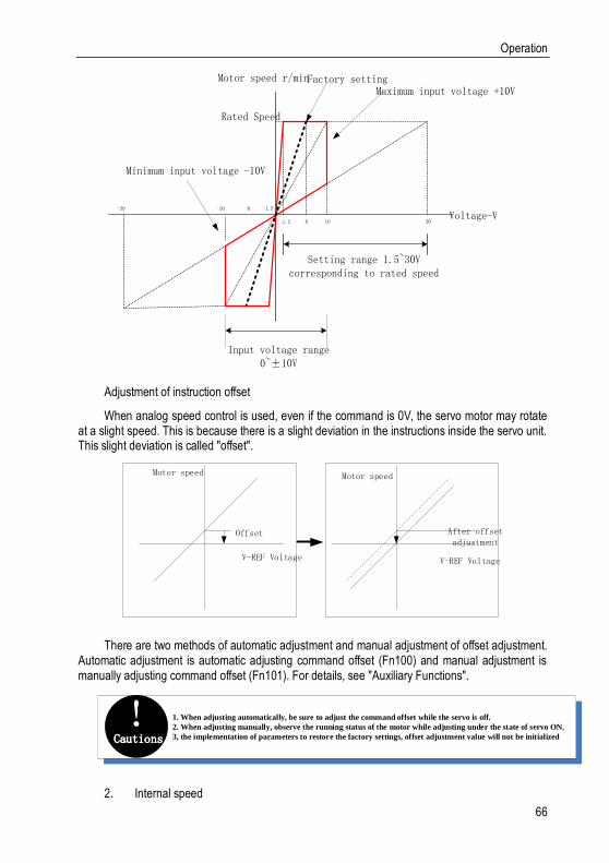
Operation
66
Input voltage range 0~±10V
Setting range 1.5~30V corresponding to rated speed
Maximum input voltage +10V
Rated Speed
Motor speed r/min
-30 -10 -6 -1.5
1.5 6 10 30
Minimum input voltage -10V
Factory setting
Voltage-V
Adjustment of instruction offset
When analog speed control is used, even if the command is 0V, the servo motor may rotate at a slight speed. This is because there is a slight deviation in the instructions inside the servo unit. This slight deviation is called "offset".
Motor speed
Offset
V-REF Voltage
Motor speed
After offset adjustment
V-REF Voltage
There are two methods of automatic adjustment and manual adjustment of offset adjustment. Automatic adjustment is automatic adjusting command offset (Fn100) and manual adjustment is manually adjusting command offset (Fn101). For details, see "Auxiliary Functions".
Cautions! 1. When adjusting automatically, be sure to adjust the command offset while the servo is off.
2. When adjusting manually, observe the running status of the motor while adjusting under the state of servo ON.
3, the implementation of parameters to restore the factory settings, offset adjustment value will not be initialized
2. Internal speed

Operation
67
Function code
Parameter name
Range Defaults Unit Communication
address When enabled
Pn304 Pn305 Pn306
Internal speed 1
0~10000 100 rpm 0x0304 Immediately
Internal speed 2
0~10000 200 rpm 0x0305 Immediately
Internal speed 3
0~10000 300 rpm 0x0306 Immediately
When operating in the internal speed mode, the servo unit provides 3 internal speed commands and selects A and B through the internal speed command of the switch.
The speed is selected through the digital input signal control:
Switch input signal Direction of speed instruction Speed instruction size
/SPD-D /SPD-A /SPD-B
OFF
OFF OFF
Positive
0
OFF ON Internal speed 1(Pn304)
ON ON Internal speed 2(Pn305)
ON OFF Internal speed 3(Pn306)
ON
OFF OFF
Negative
0
OFF ON Internal speed 1(Pn304)
ON ON Internal speed 2(Pn305)
ON OFF Internal speed 3(Pn306)
Soft Start 5.3.3.
The soft start function is a speed command that converts a step speed command to a smoother constant acceleration/deceleration. You can set the acceleration time and deceleration time, and use this function when you want to achieve smooth speed control during speed control.
Function code
Parameter name
Range Defaults Unit Communication
address When
enabled
Pn310
Speed command trapezoidal acceleration
time
0~10000
0 ms 0x0310 Immediately
Acceleration of the set speed from 0r/min to the rated speed (corresponding to the motor model). When the given speed is greater or less than the rated speed, the actual acceleration time is calculated in proportion.
Pn311
Speed command trapezoidal
deceleration time
0~10000
0 ms 0x0311 Immediately
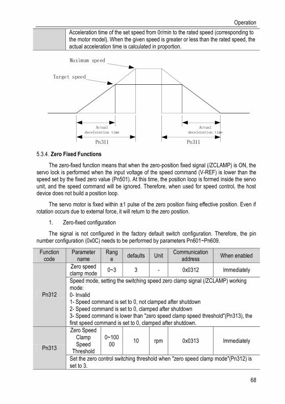
Operation
68
Acceleration time of the set speed from 0r/min to the rated speed (corresponding to the motor model). When the given speed is greater or less than the rated speed, the actual acceleration time is calculated in proportion.
Target speed
Actual deceleration time
Maximum speed
Pn311
Actual deceleration time
Pn311
Zero Fixed Functions 5.3.4.
The zero-fixed function means that when the zero-position fixed signal (/ZCLAMP) is ON, the servo lock is performed when the input voltage of the speed command (V-REF) is lower than the speed set by the fixed zero value (Pn501). At this time, the position loop is formed inside the servo unit, and the speed command will be ignored. Therefore, when used for speed control, the host device does not build a position loop.
The servo motor is fixed within ± 1 pulse of the zero position fixing effective position. Even if rotation occurs due to external force, it will return to the zero position.
1. Zero-fixed configuration
The signal is not configured in the factory default switch configuration. Therefore, the pin number configuration (0x0C) needs to be performed by parameters Pn601~Pn609.
Function code
Parameter name
Range
defaults Unit Communication
address When enabled
Pn312
Zero speed clamp mode
0~3 3 - 0x0312 Immediately
Speed mode, setting the switching speed zero clamp signal (/ZCLAMP) working mode: 0- Invalid 1- Speed command is set to 0, not clamped after shutdown 2- Speed command is set to 0, clamped after shutdown 3- Speed command is lower than "zero speed clamp speed threshold"(Pn313), the first speed command is set to 0, clamped after shutdown.
Pn313
Zero Speed Clamp Speed
Threshold
0~10000
10 rpm 0x0313 Immediately
Set the zero control switching threshold when "zero speed clamp mode"(Pn312) is set to 3.
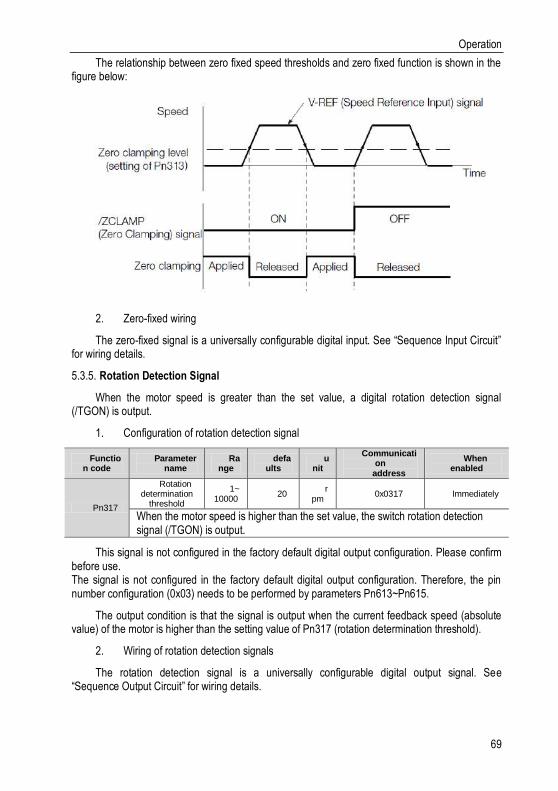
Operation
69
The relationship between zero fixed speed thresholds and zero fixed function is shown in the figure below:
2. Zero-fixed wiring
The zero-fixed signal is a universally configurable digital input. See “Sequence Input Circuit” for wiring details.
Rotation Detection Signal 5.3.5.
When the motor speed is greater than the set value, a digital rotation detection signal (/TGON) is output.
1. Configuration of rotation detection signal
Function code
Parameter name
Range
defaults
unit
Communication
address
When enabled
Pn317
Rotation determination
threshold
1~10000
20 r
pm 0x0317 Immediately
When the motor speed is higher than the set value, the switch rotation detection signal (/TGON) is output.
This signal is not configured in the factory default digital output configuration. Please confirm before use. The signal is not configured in the factory default digital output configuration. Therefore, the pin number configuration (0x03) needs to be performed by parameters Pn613~Pn615.
The output condition is that the signal is output when the current feedback speed (absolute value) of the motor is higher than the setting value of Pn317 (rotation determination threshold).
2. Wiring of rotation detection signals
The rotation detection signal is a universally configurable digital output signal. See “Sequence Output Circuit” for wiring details.

Operation
70
Consistent Speed 5.3.6.
The speed coincidence signal (/V-CMP) is a signal that is output when the difference between the speed of the servo motor and the command speed is equal to or lowers than the set value of the speed coincidence range Pn320. Used when interlocking with the upper device. This signal is the output signal during speed control.
1. Configuration of Speed-consistent Signals
Function code
Parameter name
Range
Defaults
Unit
Communication
address
When enabled
Pn320
Speed consistent
range
0~100
10 r
pm 0x0320 Immediately
When the difference between the motor speed and the command speed is lower than the set value, the switch-speed match signal (/V-CMP) is output.
In the factory default digital output configuration, the signal is configured as CN129 and 30 pin numbers (Pn614=0x02) by default. Please confirm before use.
If Pn320 is set to 100 and the speed reference is 2000mm-1, the signal would be output when the motor speed is between 1900 mm-1and 2100 mm-1.

Operation
71
Pn320
Motor speed
Speed command
Within the two dashed lines / V-CMP output
For example: Pn320=100, when the speed command is 2000r, min, the feedback speed is 1900~2100r/min, signal output
Pn320
2. Wiring of speed-consistent signals
The speed-consistent signal is a universally configurable digital output signal. For details on wiring, see "Sequence Output Circuit".
Torque Mode 5.4.
Refer to "Connection Example of Torque Control" for details on the wiring related to the torque mode. It is selected by control mode selection (Pn000=2). The torque mode is divided into the internal torque command (Pn400=0) and the analog torque command (Pn400=1, factory default) by the selection of the torque command source.
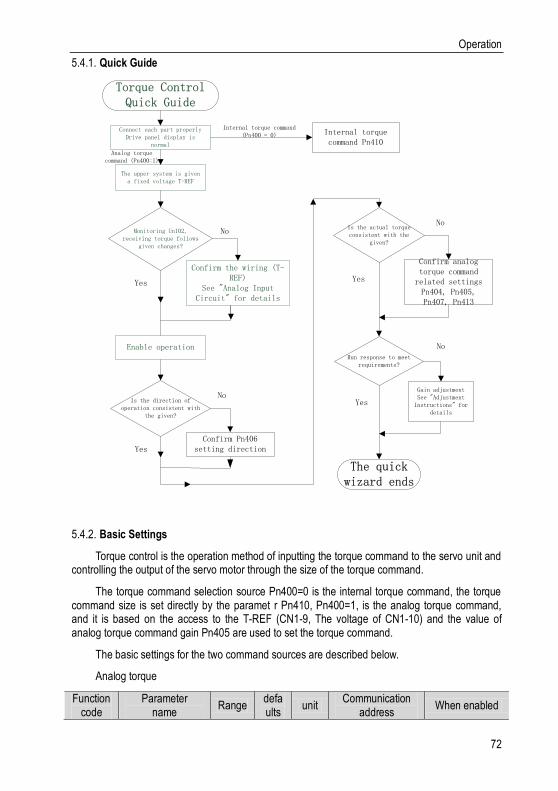
Operation
72
Quick Guide 5.4.1.
Enable operation
Monitoring Un102, receiving torque follows
given changes?
Connect each part properlyDrive panel display is
normal
The upper system is given a fixed voltage T-REF
Confirm the wiring (T-REF)
See "Analog Input Circuit" for details
No
Yes
Is the direction of operation consistent with
the given?
Confirm Pn406 setting directionYes
No
Is the actual torque consistent with the
given?
Confirm analog torque command
related settingsPn404, Pn405, Pn407, Pn413
Yes
No
Run response to meet requirements?
Gain adjustmentSee "Adjustment
Instructions" for details
No
Yes
The quick wizard ends
Torque Control Quick Guide
Internal torque command Pn410
Internal torque command (Pn400 = 0)
Analog torque command (Pn400=1)
Basic Settings 5.4.2.
Torque control is the operation method of inputting the torque command to the servo unit and controlling the output of the servo motor through the size of the torque command.
The torque command selection source Pn400=0 is the internal torque command, the torque command size is set directly by the paramet r Pn410, Pn400=1, is the analog torque command, and it is based on the access to the T-REF (CN1-9, The voltage of CN1-10) and the value of analog torque command gain Pn405 are used to set the torque command.
The basic settings for the two command sources are described below.
Analog torque
Function code
Parameter name
Range defaults
unit Communication
address When enabled
Operation
73
Pn404
Analog torque command filter
time
0~655.35
0.00 ms 0x0404 Immediately
The parameter is used to smooth the torque command when we apply a delay filter to the analog torque command (T-REF) input, usually it does not need to be changed. If the set value is too large, the responsiveness may decrease. So please set it up as we check the response.
Pn405
Analog torque command gain
10~100
30
0.1V/Rated
speed
0x0405 Immediately
This parameter is used to set the analog voltage value (T-REF) required for the rated torque of the servo motor. Caution: Do not apply more than -10~10V, exceeding this range may cause damage to the driver.
Pn406
Analog torque command negation
0~1 0 - 0x0406 Immediately
The analog voltage corresponds to the polarity setting of the torque command: 0- Positive polarity: Positive voltage corresponds to positive torque command. 1- Negative polarity: Positive voltage corresponds to negative torque command.
Pn407
Analog torque command dead
zone range 0~3 0 V 0x0407 Immediately
In analog torque control, even if the input command is 0V, the servo motor may rotate at a slight speed. This is because a slight deviation occurs in the command inside the servo unit. This error can be eliminated by setting an appropriate analog torque command deadband range.
Inner torque
Function code
Parameter name
Range Defaults Unit Communication address
When enabled
Pn410
Internal torque command in torque control
-500~500 0 % 0x0410 Immediately
The command source for selecting the torque control is the torque command size setting for internal setting.
Set the analog voltage value of the speed command (T-REF, see “Analog Input Circuit” for wiring) to make the speed of the servo motor the rated value through the analog speed command gain Pn405.
Example: The factory default parameter Pn405=30 (3V corresponds to the rated torque). If the input voltage at the T-REF terminal is 1.5V, the torque command corresponds to 50%. If 3V is input, the torque command corresponds to 100%.
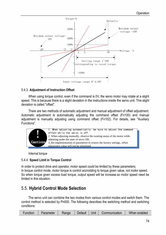
Operation
74
Input voltage range 0~±10V
Setting range 1~10V corresponding to rated torque
Maximum output voltage +10V
100%
Torque-%
-10 -3 -1
1 3 10
Minimum output voltage-10V
Defaults
Voltage -V
200%
350%
-350%
Adjustment of Instruction Offset 5.4.3.
When using torque control, even if the command is 0V, the servo motor may rotate at a slight speed. This is because there is a slight deviation in the instructions inside the servo unit. This slight deviation is called "offset".
There are two methods of automatic adjustment and manual adjustment of offset adjustment. Automatic adjustment is automatically adjusting the command offset (Fn100) and manual adjustment is manually adjusting using command offset (Fn102). For details, see "Auxiliary Functions".
Cautions
!1. When adjusting automatically, be sure to adjust the command offset while the servo is off.2. When adjusting manually, observe the running status of the motor while
adjusting under the state of servo ON.
3, the implementation of parameters to restore the factory settings, offset
adjustment value will not be initialized
Internal torque
Speed Limit in Torque Control 5.4.4.
In order to protect drive and operator, motor speed could be limited by these parameters; In torque control mode, motor torque is control accrodding to torque given value, not motor speed. So when torque given excess load torque, output speed will be increase.so motor speed need be limited in this situation.
Hybrid Control Mode Selection 5.5.
The servo unit can combine the two modes from various control modes and switch them. The control method is selected by Pn000. The following describes the switching method and switching conditions:
Function Parameter Range Default Unit Communication When enabled
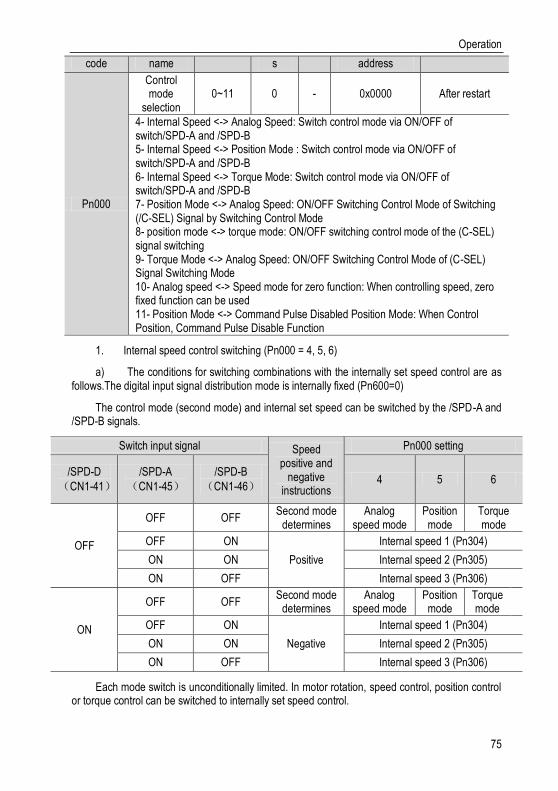
Operation
75
code name s address
Pn000
Control mode
selection 0~11 0 - 0x0000 After restart
4- Internal Speed <-> Analog Speed: Switch control mode via ON/OFF of switch/SPD-A and /SPD-B 5- Internal Speed <-> Position Mode : Switch control mode via ON/OFF of switch/SPD-A and /SPD-B 6- Internal Speed <-> Torque Mode: Switch control mode via ON/OFF of switch/SPD-A and /SPD-B 7- Position Mode <-> Analog Speed: ON/OFF Switching Control Mode of Switching (/C-SEL) Signal by Switching Control Mode 8- position mode <-> torque mode: ON/OFF switching control mode of the (C-SEL) signal switching 9- Torque Mode <-> Analog Speed: ON/OFF Switching Control Mode of (C-SEL) Signal Switching Mode 10- Analog speed <-> Speed mode for zero function: When controlling speed, zero fixed function can be used 11- Position Mode <-> Command Pulse Disabled Position Mode: When Control Position, Command Pulse Disable Function
1. Internal speed control switching (Pn000 = 4, 5, 6)
a) The conditions for switching combinations with the internally set speed control are as follows.The digital input signal distribution mode is internally fixed (Pn600=0)
The control mode (second mode) and internal set speed can be switched by the /SPD-A and /SPD-B signals.
Switch input signal Speed positive and
negative instructions
Pn000 setting
/SPD-D
(CN1-41)
/SPD-A
(CN1-45)
/SPD-B
(CN1-46) 4 5 6
OFF
OFF OFF Second mode
determines Analog
speed mode Position mode
Torque mode
OFF ON
Positive
Internal speed 1 (Pn304)
ON ON Internal speed 2 (Pn305)
ON OFF Internal speed 3 (Pn306)
ON
OFF OFF Second mode
determines Analog
speed mode Position mode
Torque mode
OFF ON
Negative
Internal speed 1 (Pn304)
ON ON Internal speed 2 (Pn305)
ON OFF Internal speed 3 (Pn306)
Each mode switch is unconditionally limited. In motor rotation, speed control, position control or torque control can be switched to internally set speed control.
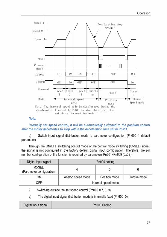
Operation
76
Speed 3
Speed 2
Speed 1
/COIN
Command pulse
/SPD-A
/SPD-B
OFF
ON
ON ON
ON OFF
OFF
OFF
OFF
OFF
OFF
ON
Speed 1
Speed2
Speed3
Switching
Pulse Speed 1
Internal speed mode
Position mode
Internal Speed mode
Deceleration stop (Pn311)
Command
Mode
Note: The internal speed mode is decelerated during the deceleration time set by Pn311 to stop the motor, then
switch to the position mode.
Note:
Internally set speed control, it will be automatically switched to the position control after the motor decelerates to stop within the deceleration time set in Pn311.
b) Switch input signal distribution mode is parameter configuration (Pn600=1 default parameter)
Through the ON/OFF switching control mode of the control mode switching (/C-SEL) signal, the signal is not configured in the factory default digital input configuration. Therefore, the pin number configuration of the function is required by parameters Pn601~Pn609 (0x0B).
Digital input signal Pn000 setting
/C-SEL (Parameter configuration)
4 5 6
ON Analog speed mode Position mode Torque mode
OFF Internal speed mode
2. Switching outside the set speed control (Pn000 = 7, 8, 9)
a) The digital input signal distribution mode is internally fixed (Pn600=0).
Digital input signal Pn000 Setting

Operation
77
/C-SEL(CN1-41)
(parameter
configuration)
7 8 9
ON Analog speed mode Torque mode Analog speed mode
OFF Position mode Position mode Torque mode
b) Switch input signal distribution mode is parameter configuration (Pn600=1 default parameter).
Digital input signal Pn000 Setting
/C-SEL (Parameter
configuration) 7 8 9
ON Analog speed mode Torque mode Analog speed mode
OFF Position mode Position mode Torque mode
3. Internally set speed control switching (Pn000 = 10, 11)
a) The digital input signal distribution mode is internally fixed (Pn600=0)
Digital input signal
Pn000 setting
/C-SEL
(CN1-41) 10 11
ON Speed mode with zero fixed
function Positioning mode with command pulse inhibit
function
OFF Speed mode Position control
b) Switch input signal distribution mode is parameter configuration (Pn600=1 default parameter)
Switch input signal Pn000 Setting
10 11
/ZCLAMP
(parameter
configuration)
ON Speed mode with zero
fixed function (*1) -
OFF Speed mode -
/INHIBIT
(parameter
configuration)
ON - Positioning mode with command pulse
inhibit function
OFF - Position control
*1: The effective mode of the digital zero-speed clamp signal (/ZCLAMP) must be used in conjunction with the setting of parameters Pn312 and Pn313. For details, see the description of the function code.
Operation
78
Other Output Signals 5.6.
Servo Ready Output Signal 5.6.1.
The servo ready output signal (/S-RDY) is a signal that indicates that the servo unit can receive servo ON (/S-ON) signals and command signals.
This signal is output under the following conditions:
The main circuit power is on. For details on the output timing of /S-RDY during power-on, see "Power-up enable ON timing".
Non-hardwired base blocking status
No alarm occurred
When using an absolute encoder, the SEN signal turns ON (H level)
1. Servo-ready parameter configuration
In the factory default digital output configuration, the signal is configured as CN1's 25th and 26th pin numbers (Pn613=0x00) by default. Please confirm before use.
2. Servo ready wiring
The servo ready signal is a universal configurable digital output. See "Sequence Output Circuit" for wiring details.
Warning Output Signal 5.6.2.
The warning output signal (/WARN) is a warning function before the alarm, which makes it easier for the host device to judge the operation of the servo unit in advance. For detailed warning code, please refer to "Warning Code".
3. Configuration of warning output signals
This signal is not configured in the factory default digital output configuration. The pin number configuration (0x07) needs to be performed by parameters Pn613~Pn615.
4. Wiring of warning output signals
The warning output signal is a universally configurable digital output signal. See “Sequence Output Circuit” for wiring details.
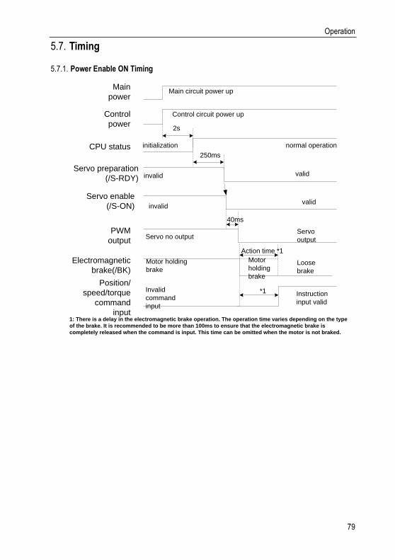
Operation
79
Timing 5.7.
Power Enable ON Timing 5.7.1.
Main
power
Control
power
PWM
output
Electromagnetic
brake(/BK)
Servo enable
(/S-ON)
CPU status
1: There is a delay in the electromagnetic brake operation. The operation time varies depending on the type
of the brake. It is recommended to be more than 100ms to ensure that the electromagnetic brake is
completely released when the command is input. This time can be omitted when the motor is not braked.
Position/
speed/torque
command
input
2s
*1
Control circuit power up
Main circuit power up
normal operation
Servo no output
Loose
brake
Motor holding
brake
Servo
output
Invalid
command
input
Instruction
input valid
Action time *1
initialization
Servo preparation
(/S-RDY)
250ms
invalid valid
40ms
Motor
holding
brake
validinvalid

Adjustment
80
Power-Off Enable OFF Timing 5.7.2.
Main
power
Control
power
PWM
output
Brake chain
signal (/BK)
output
1: Undervoltage fault occurs when the control power supply voltage drops below 170V/350V (220V series/400V series)
2: Output from /BK to the actual brake of the motor. The time varies depending on the type of the brake. See "Electromagnetic brake" for
the timing of the /BK signal when the alarm or enable is OFF.
*1 Power off the
control circuit
Main circuit
loses power
Servo
output
Motor
holding
brakeLoose
brake
Servo no
output
*2
valid
Note 4
Position/
speed/torque
command
input
invalid
Loose
brake
Adjustment 6.
Adjustments 6.1.
Adjustments Steps 6.1.1.
Adjustments refer to optimaize the function of responsiveness by adjusting the servo unit’s servo gain. Servo gain is set by the combinations of many parameters, including speed circle gain, position circle gain, filter, friction compensation, rotation inertia and so on. These paramenters would influence with each other, so you must take the balance among all paramenters into the consideration while setting. The factory settings of the servo gain are stable settings. Use all the adjusting functions according to the uses’ mechanical conditions in order to improve the responsiveness. The following figure is basic adjustment procedure flow chart; please adjust the machine according to the status and operating conditions of the machine.

Adjustment
81
Smart settings adjustment via no
instructions
Is the adjustment result satisfactory?
Adjust with robust control
Yes
No
Is the adjustment result satisfactory?
Starting adjusting
Adjust with broadband settings
Is the adjustment result
satisfactory?
Adjust with broadband settings
Is the adjustment result
satisfactory?
No
No
No
End
Yes
End
End
End
Yes
Yes
No
Safety Precautions When Adjusting 6.1.2.
When you are making adjustments, please set the servopack protection functions shown below under appropriate conditions.
Set the overtravel
Please set the overtravel and you could refer to the servo enable and overtravel setting if you want more details.
The settings of the torque limit

Adjustment
82
The torque limit function is about calculate the torque that mechanical motions need in order to make sure that the torque is not greater than this troque limit value. If the torque is set below the value required for operation, overshoot or vibration may occur.
See more details in the “torque limit”.
Set excessive position deviation alarm value
The excessive position deveiation alarm is an effective protection function when we are using servo unit for position control. When the motor operation does not match the command, you can detect the abnormal condition and stop the motor by setting an appropriate position deviation alarm. The position deviation is the difference between the position command value and the actual position. The position deviation can be expressed by the relationship between the following position loop gain (Pn103) and motor speed.
Position deviationinstruction unit
=Motor speed[min−1]
60∗
Encoder resolution∗1
Pn103[0.1 s⁄ ] 102⁄∗
Pn206
Pn204
When the acceleration/deceleration of the position command exceeds the tracking ability of the motor, the follow-up hysteresis will become large, resulting in the positional deviation not satisfying the above relation. Please reduce the acceleration and deceleration of the position command to the value that can be tracked by the motor or increase the value of the excessive position error alarm.
Set the vibration detection function
Please initialize (Fn105) the detection value detected by the vibration and set an appropriate value for the vibration detection function. For details, refer to the corresponding "Accessibility"
Set excessive position deviation alarm value when servo is ON
If the servo is turned ON while the position deviation is accumulated, the motor will return to the original position to make the position deviation "0"and avoid causing a danger. In order to avoid this kind of situation, you can set an excessive position deviation alarm value when the servo is turned on to restrict the operation.

Adjustment
83
Robust Control 6.2.
In factory default, the robust control function is valid. When resonance and vibration occur, please change the attune value and load value via Fn301 or set Pn177 and Pn178.
Profile 6.2.1.
Robust function could get stable response through adjusting the whole system automatically no matter what kind of mechanisim or fluctuation of load.
Function code Name Range Defaul
t Uni
t Communication address
When enabled
Pn175
Robust control
selection
0x00~0x01
1 - 0x0175 After
restart
Set the robust control function switch: 0-invalid 1-valid
Pn177
Robust control tuning value
10~80 40.0 Hz 0x0177 Immediatel
y
Set a greater robust control gain tuning value, systematic response gets faster, but system overshoot and excessive noise may occur
Pn178
The minmum value of robust control
0~500 0 % 0x0178 Immediatel
y
Set a greater load ratio of robust control, systematic response gets faster, but the systematic excessive noise may occur, and we could increase this value in order
to decrease the over-sdjustment and overshoot when torque is excessive.
Robust control function is valid in position control or speed control and invalid in torque control. When robust control is valid, some of the control functions of the table below would be restrained.
Function name Operation Executable conditions and
notes
Vibration detection value initialization (Fn105)
Yes
Robust control is invalid in operation, and it turns to be valid when the operation is
over
Bandwidth setting(Fn303) No
EasyFFT (Fn401) Yes
Robust control is invalid in operation, and it turns to be valid when the operation is
over

Adjustment
84
Gain shift No
Inertia recognization Yes
Robust control is invalid in operation, and it turns to be valid when the operation is
over
Mechanical analysis Yes
Robust control is invalid in operation, and it turns to be valid when the operation is
over
Parameters which become invalid when robust control function are valid. When we set robust
control function valid in factory default, the Pn100、Pn101、Pn102, Pn103, Pn105, Pn106, Pn107,
Pn140, Pn110, Pn170 are invalid.
Steps 6.2.2.
Robust control function could be set via the auxiliary function Fn301 on panel operator and more details on”Accessibility”, or we could set relevant parameters via”parameters setting”
Caution! Before operating the robust control function, please confirm the setting
below, if not, it will display �NO-OP in operation:1. Robust control function is valid (Pn175=1)2. No-motor debugging function is invalid (Pn730=0)
Supplement 6.2.3.
In robust control, due to the increase of the tuning value, the system may cause resonance noise. You can set the Pn151 to choose whether to automatically set the notch. The factory default is “Auto-tuning”. Only when the corresponding notch function is not needed, it is set to “Auto-adjust without auxiliary function.”
Function code
Name Range default Unit Communication
address When
enabled
Pn151
Automatic adjustment
and selection of notch filter
2
0x00~0x01
1 - 0x0151 Immediately
0-No automatic adjustment via auxiliary functions 1-Automatic adjustment via auxiliary functions
Relevant Parameters 6.2.4.
The parameters need to be set are shown as below when operating robust control function:
Parameter Name
Pn175 Robust switch
Pn104 First torque command filter

Adjustment
85
Pn156 Second notch filter frequency
Pn157 Second stage notch filter Q value
Adjustment
86
Inertia Recognition 6.3.
Profile: 6.3.1.
Inertia recognition means that the servo unit performs automatic operation (forward and reverse reciprocating motion) without issuing commands from the upper device, and the load inertia moment is recognized during operation. The rotary inertia ratio (ratio of load inertia to motor rotor inertia) is the reference parameter for performing the gain adjustment, and the correct value must be set as far as possible. The load moment of inertia can be calculated based on the weight and composition of each part of the machine, but the operation is very tedious. With this function, after the motor is driven several times in the positive/negative direction, a high-precision load moment of inertia value can be obtained.
The motor operates according to the following operating specifications.
The highest speed: ± 1000min-1 (changeable)
Acceleration: ± 20000min-1/s (changeable)
Travel distance: maximum ± 2.5 turns (changeable)
Steps 6.3.2.
The inertia recognition function can only be identified by the upper computer debugging software VCSDsoft. For details on the identification procedure, refer to “Upper Position Debugging Related” - “Inertia Identification”.
Supplyment 6.3.3.
When identifying the inertia, please make sure that the system can operate the range and set the operating conditions reasonably according to the operable range. Under different operating conditions, the recognition result may have minor deviations.
If the servo torque limit is set too small, the result of inertia identification may be affected, resulting in discrepancy between the identification result and the actual inertia. Please confirm before identification.
After inertia identification, after changing the inertia ratio (Pn100), the original gain-related parameters of the servo system need to be re-adjusted, otherwise vibration and noise may occur.
Adjustment
87
Intelligent Setting 6.4.
Profile 6.4.1.
Users can choose intelligent setting with command input and no command input
No command input
It means the function of automatically adjusting the servo unit according to the mechanical characteristics when the automatic operation (forward and reverse reciprocating motions) is performed within the set range. Intelligent settings can be performed without connection to the control system. The automatic operation is as follows
Highest speed: motor rated speed
Acceleration torque: motor rated torque about 100%
Move distance: can be set arbitrarily. The factory setting is equivalent to 3 turns of the motor
Command input
It is the method of automatically adjusting the running command from the host control system. The command intelligent setting can also be used for additional adjustments after the commandless intelligent setting. When the correct moment of inertia ratio is set, no-instruction intelligent setting can be omitted, and only the intelligent setting operation with instructions is performed.
Cautions! The command smart setting starts with the current speed loop gain (Pn101) as a
reference. If vibration occurs at the start of the adjustment, correct adjustment cannot be performed. In this case, lower the speed loop gain (Pn101) until the vibration disappears, and then readjust.
The intelligent setting process adjusts the following items:
Moment of inertia ratio (intelligent setting without command)
Gain adjustment (speed loop gain, position loop gain, etc.)
Filter adjustment (torque command filter, notch filter)
Friction compensation
IF suppression control
Vibration suppression
Low-frequency vibration suppression (only when Mode = 2 or 3) (without command smart setting)
Steps 6.4.2.
The intelligent setting function cannot be set by the panel operator, and it needs to cooperate with the host computer debugging software to perform related operations. The instructionless intelligent setting is slightly different from the related operation of the instructional intelligent setting.
Adjustment
88
For detailed steps, see "host computer operation instructions" - "Intelligent setting".
Confirmation before execution
Before performing intelligent settings, be sure to confirm the following settings. If set incorrectly, this function cannot be performed during operation.
No overtravel has occurred
No torque control
Gain switching selection switch is manual gain switching (Pn110 = 0) and is the first gain
No motor test function is invalid (Pn730 = 0)
No alarm or warning occurred
Robust control function is invalid (Pn175 = 0)
Cautions! 1. When the commandless intelligent setting is executed in the speed control status, it
will automatically switch to position control to perform adjustment, and return speed control after adjustment is completed.2. The intelligent command setting cannot be executed in the speed control status.3. During the intelligent setting process, the command pulse input override switch function becomes invalid.
Failed to perform adjustment or adjustment failed example
In the following occasions, intelligent settings will not be performed properly. Please use the bandwidth setting (see "Bandwidth setting" for details).
The motor is in power (in servo ON) in position control (with command intelligent setting)
When the mechanical system can only run in one direction
The scope of activities is narrow, below 0.5 laps
When the moment of inertia changes within the set operating range
When the mechanical dynamic friction is large
The mechanical rigidity is low and vibration occurs during positioning
When P (proportional) control is selected, "Load inertia moment measurement" is selected, In the moment of inertial recognition, or when switching from P/CON signal to P control
When using the mode switch, when "Load moment of inertia measurement" is selected, the mode switch function becomes invalid during the moment of inertia recognition and becomes PI control. The mode switch function becomes active again after the moment of inertia recognition is completed.
When speed feed forward and torque feed forward are input
When the positioning complete width (Pn262) is small
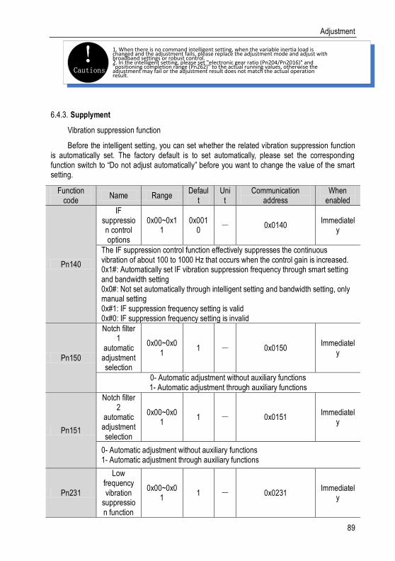
Adjustment
89
Cautions! 1. When there is no command intelligent setting, when the variable inertia load is
changed and the adjustment fails, please replace the adjustment mode and adjust with broadband settings or robust control.2. In the intelligent setting, please set "electronic gear ratio (Pn204/Pn2016)" and "positioning completion range (Pn262)" to the actual running values, otherwise the adjustment may fail or the adjustment result does not match the actual operation result.
Supplyment 6.4.3.
Vibration suppression function
Before the intelligent setting, you can set whether the related vibration suppression function is automatically set. The factory default is to set automatically, please set the corresponding function switch to “Do not adjust automatically” before you want to change the value of the smart setting.
Function code
Name Range Defaul
t Uni
t Communication
address When
enabled
Pn140
IF suppression control options
0x00~0x11
0x0010
- 0x0140 Immediatel
y
The IF suppression control function effectively suppresses the continuous vibration of about 100 to 1000 Hz that occurs when the control gain is increased. 0x1#: Automatically set IF vibration suppression frequency through smart setting and bandwidth setting 0x0#: Not set automatically through intelligent setting and bandwidth setting, only manual setting 0x#1: IF suppression frequency setting is valid 0x#0: IF suppression frequency setting is invalid
Pn150
Notch filter 1
automatic adjustment selection
0x00~0x01
1 - 0x0150 Immediatel
y
0- Automatic adjustment without auxiliary functions 1- Automatic adjustment through auxiliary functions
Pn151
Notch filter 2
automatic adjustment selection
0x00~0x01
1 - 0x0151 Immediatel
y
0- Automatic adjustment without auxiliary functions 1- Automatic adjustment through auxiliary functions
Pn231
Low frequency vibration
suppression function
0x00~0x01
1 - 0x0231 Immediatel
y
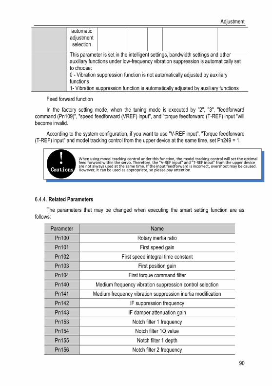
Adjustment
90
automatic adjustment selection
This parameter is set in the intelligent settings, bandwidth settings and other auxiliary functions under low-frequency vibration suppression is automatically set to choose: 0 - Vibration suppression function is not automatically adjusted by auxiliary functions 1- Vibration suppression function is automatically adjusted by auxiliary functions
Feed forward function
In the factory setting mode, when the tuning mode is executed by "2", "3", "feedforward command (Pn109)", "speed feedforward (VREF) input", and "torque feedforward (T-REF) input "will become invalid.
According to the system configuration, if you want to use "V-REF input", "Torque feedforward (T-REF) input" and model tracking control from the upper device at the same time, set Pn249 = 1.
Cautions! When using model tracking control under this function, the model tracking control will set the optimal
feed forward within the servo. Therefore, the "V-REF input" and "T-REF input" from the upper device are not always used at the same time. If the input feedforward is incorrect, overshoot may be caused. However, it can be used as appropriate, so please pay attention.
Related Parameters 6.4.4.
The parameters that may be changed when executing the smart setting function are as follows:
Parameter Name
Pn100 Rotary inertia ratio
Pn101 First speed gain
Pn102 First speed integral time constant
Pn103 First position gain
Pn104 First torque command filter
Pn140 Medium frequency vibration suppression control selection
Pn141 Medium frequency vibration suppression inertia modification
Pn142 IF suppression frequency
Pn143 IF damper attenuation gain
Pn153 Notch filter 1 frequency
Pn154 Notch filter 1Q value
Pn155 Notch filter 1 depth
Pn156 Notch filter 2 frequency

Adjustment
91
Pn157 Notch Filter 2Q Value
Pn158 Notch filter 2 depth
Pn240 Model tracking control selection
Pn241 Model tracking control gain
Pn242 Model tracking control attenuation coefficient
Pn243 Model tracking control speed feed forward gain
Pn244 Model tracking control forward torque feed forward gain
Pn245 Model tracking control reverse torque feed forward gain
Bandwidth Setting 6.5.
Profile 6.5.1.
The bandwidth setting is a method of inputting a speed command or a position command from the host device, and manually adjusting the running speed.
By adjusting one or two values with the bandwidth setting, the relevant servo gain setting can be automatically adjusted.
The bandwidth setting adjusts the following items:
Gain adjustment (speed loop gain, position loop gain, etc.)
Filter adjustment (torque command filter, notch filter)
Friction compensation
IF suppression control
Low frequency vibration suppression
Use the bandwidth setting when you cannot achieve satisfactory response characteristics after setting it by smart settings. If you want to further fine-tune each servo gain after adjusting the bandwidth setting, see “Manual adjustment” for manual tuning.
Steps 6.5.2.
Before performing bandwidth setting, be sure to confirm the following settings. If it is set incorrectly, "NO-OP" will be displayed in the operation and this function cannot be performed.
Invalid selection of no motor test function (Pn730 = 0)
Robust control selection is invalid (Pn175 = 0)
Tuning mode is set to 0 or 1 when tuning is performed by speed control
The bandwidth setting procedure can be performed by any one of the panel operator or the upper level debugging software. However, the panel operator can only operate when the tuning mode is set to “0-stability” or “1-high response”. For detailed operation procedure, see “Bandwidth Setting (Fn303)”. When positioning-specific adjustments "2-positioning" and "3-positioning are not required to be over-tuned" are required, they must be used in conjunction with "host computer

Adjustment
92
debugging software".
Cautions! After the inertia recognition or intelligent setting correctly set the moment of inertia
ratio (Pn100), perform the broadband setting operation.
Supplyment 6.5.3.
Viabration suppression function
Before setting the bandwidth, you can set whether the related vibration suppression function is automatically set. The factory default is to set automatically. Please set the corresponding function switch to “Do not adjust automatically” before you want to change its value through the bandwidth setting.
Function code
Name Range Defaul
t Uni
t Communication
address When
enabled
Pn140
IF suppression control options
0x00~0x11
0x0010
- 0x0140 Immediatel
y
The IF suppression control function effectively suppresses the continuous vibration of about 100 to 1000 Hz that occurs when the control gain is increased. 0x1#: Automatically set IF vibration suppression frequency through smart setting and bandwidth setting 0x0#: Not set automatically through intelligent setting and bandwidth setting, only manual setting 0x#1: IF suppression frequency setting valid 0x#0: IF suppression frequency setting invalid
Pn150
Notch filter 1
automatic adjustment selection
0x00~0x01
1 - 0x0150 Immediatel
y
0- Automatic adjustment without auxiliary functions 1- Automatic adjustment through auxiliary functions
Pn151
Notch filter 2
automatic adjustment selection
0x00~0x01
1 - 0x0151 Immediatel
y
0- Automatic adjustment without auxiliary functions 1- Automatic adjustment through auxiliary functions
Pn231 Low
frequency vibration
0x00~0x01
1 - 0x0231 Immediatel
y
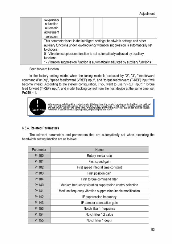
Adjustment
93
suppression function automatic
adjustment selection
This parameter is set in the intelligent settings, bandwidth settings and other auxiliary functions under low-frequency vibration suppression is automatically set to choose: 0 - Vibration suppression function is not automatically adjusted by auxiliary functions 1- Vibration suppression function is automatically adjusted by auxiliary functions
Feed forward function
In the factory setting mode, when the tuning mode is executed by "2", "3", "feedforward command (Pn109)", "speed feedforward (VREF) input", and "torque feedforward (T-REF) input "will become invalid. According to the system configuration, if you want to use "V-REF input", "Torque feed forward (T-REF) input", and model tracking control from the host device at the same time, set Pn249 = 1.
Cautions! When using model tracking control under this function, the model tracking control will set the optimal
feed forward within the servo. Therefore, the "V-REF input" and "T-REF input" from the upper device are not always used at the same time. If the input feedforward is incorrect, overshoot may be caused. However, it can be used as appropriate, so please pay attention.
Related Parameters 6.5.4.
The relevant parameters and parameters that are automatically set when executing the bandwidth setting function are as follows:
Parameter Name
Pn100 Rotary inertia ratio
Pn101 First speed gain
Pn102 First speed integral time constant
Pn103 First position gain
Pn104 First torque command filter
Pn140 Medium frequency vibration suppression control selection
Pn141 Medium frequency vibration suppression inertia modification
Pn142 IF suppression frequency
Pn143 IF damper attenuation gain
Pn153 Notch filter 1 frequency
Pn154 Notch filter 1Q value
Pn155 Notch filter 1 depth

Adjustment
94
Pn156 Notch filter 2 frequency
Pn157 Notch Filter 2Q Value
Pn158 Notch filter 2 depth
Pn240 Model tracking control selection
Pn241 Model tracking control gain
Pn242 Model tracking control attenuation coefficient
Pn243 Model tracking control speed feed forward gain
Pn244 Model tracking control forward torque feed forward gain
Pn245 Model tracking control reverse torque feed forward gain
Manual Adjustment Function 6.6.
After the intelligent setting and bandwidth setting adjustment, the function for further individual adjustment is required:
Servo Gain 6.6.1.
Deviation
counter
Position loop gain
KP
speed control deviceKV Ti
Tf Current controll
er
Power converte
rM
PG
Command input
servo motor
Encoder
Position loop
Speed loopCurrent loop
Position control loopSpeed control loop
+
-
+
-
+
-
To manually adjust the servo gain, adjust the servo gains one by one based on understanding the composition and characteristics of the servo unit. In most cases, if there is a large change in one parameter, the other parameter must be adjusted again. In order to confirm the response characteristics, preparations must be made to observe the output waveform of the analog monitor using a measuring instrument. The servo unit consists of three feedback loops (position loop, speed loop, and current loop). The more the inner loop, the more responsive it needs to be. Failure to follow this principle will result in poor responsiveness or vibration. Since the

Adjustment
95
current loop ensures sufficient responsiveness, the user does not have to make adjustments. By setting the following servo gains, the response characteristics of the servo unit can be adjusted.
Function code
parameter Range Defaul
t Uni
t Communication
address When
enabled
Pn100
Rotary inertia ratio
0~20000 100 % 0x0100 Immediatel
y
Moment of inertia ratio = load inertia of motor shaft conversion / rotor moment of inertia of servo motor *100%
Pn101
First speed gain
1~2000 40.0 Hz 0x0101 Immediatel
y
Determine the parameters of the speed loop responsiveness. If the response of the speed loop is low, it becomes a delay factor of the outer position loop, so overshoot or vibration of the speed command occurs. In the range where the mechanical system does not generate vibration, the larger the setting value, the more stable the servo system is. The better the responsiveness
Pn102
First speed integration
time constant
0.15~512
20.00 ms 0x0102 Immediatel
y
In order to respond to small input, the speed loop contains integral elements. Because this integral element is a delay element for the servo system, when the time parameter is set too large, overshoot may occur, or the positioning time may be prolonged, and the responsiveness may be deteriorated.
Pn103
First position
gain 1~2000 40.0 1/s 0x0103
Immediately
The position loop response is determined by the position loop gain. The higher the setting of the position loop gain, the higher the responsiveness and the shorter the positioning time. The position loop gain cannot be increased beyond the rigidity of the mechanical system. To increase the position loop gain to a larger value, the rigidity of the machine must be increased.
Pn104
First torque command
filter
0~655.35
1.00 ms 0x0104 Immediatel
y
Adjusting the parameters of the torque command filter may eliminate the machine vibration caused by the servo drive. The smaller the value, the better the responsiveness can be controlled. However, the conditions are restricted by the machine conditions.
Pn401
Torque command
second-order low-pass filter cut-off frequency
100~5000
5000 Hz 0x0401 Immediatel
y
Use this parameter to set the cutoff frequency of the second-order torque filter. When this parameter is set to 5000, the function of the filter is invalid.
Pn402 Torque 0.5~1 0.50 1 0x0402 Immediatel

Adjustment
96
command second-order low-pass
filter Q
y
By setting this parameter, the Q value of the second-order torque filter can be set. Increasing the Q value can improve the system responsiveness, but noise will be generated when the setting is too large.
Gain Switching 6.6.2.
The gain switching function includes "manual gain switching" that uses an external input signal and "automatic gain switching" that automatically switches. By using the gain switching function, the gain can be increased during positioning, the positioning time can be shortened, and the gain can be reduced and vibration can be suppressed when the motor stops.
Function code
Parameter name
Range Defau
lt Uni
t Communication
address When
enabled
Pn110
Gain switching
mode selection
switch
0x00~0x01
0 - 0x0110 Immediate
ly
The gain switching function includes two methods of “manual gain switching” using an external input signal and “automatic gain switching” automatically switching. By using the gain switching function, the gain can be increased during positioning, and the positioning time can be shortened when the motor is stopped. Reduce gain and suppress vibration. 0-Manual Gain Switching by Manual Gain Switching of External Input Signal (G-SEL) 1- When the automatic switching condition is established (Pn111), it automatically switches from the first gain to the second gain; otherwise, it switches back to the first gain.
Pn111
Position control gain automatic switching condition
0x00~0x05
0 - 0x0111 Immediate
ly
Set the conditions for automatic gain switching: 0-positioning completion signal ON 1- Positioning completion signal OFF 2-positioning approach signal ON 3-positioning proximity signal OFF 4-position command is 0 after filter and pulse input is OFF 5-position command pulse input ON If the condition is met, then switch to the second gain, otherwise switch to the first gain
Pn112 Gain
switching transition time
0~65535 0 ms 0x0112 Immediate
ly
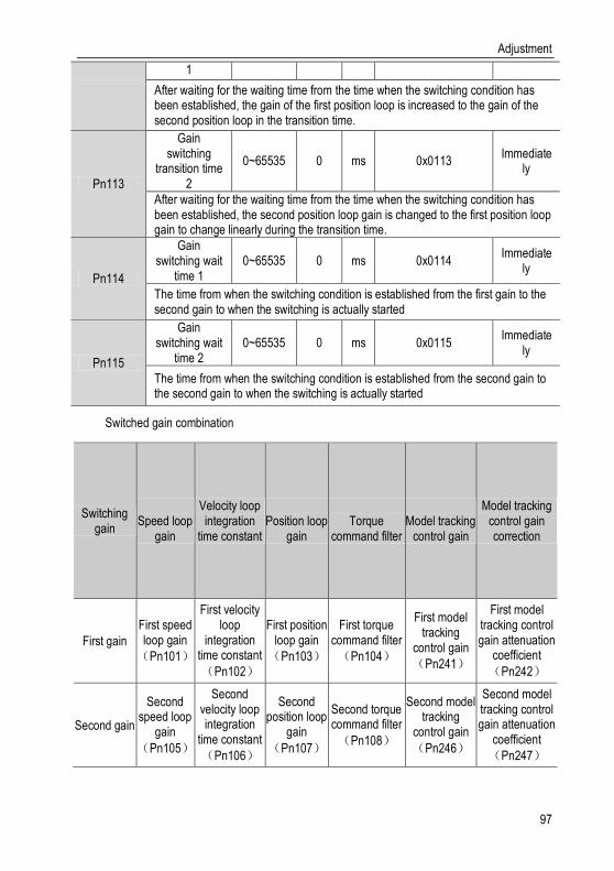
Adjustment
97
1
After waiting for the waiting time from the time when the switching condition has been established, the gain of the first position loop is increased to the gain of the second position loop in the transition time.
Pn113
Gain switching
transition time 2
0~65535 0 ms 0x0113 Immediate
ly
After waiting for the waiting time from the time when the switching condition has been established, the second position loop gain is changed to the first position loop gain to change linearly during the transition time.
Pn114
Gain switching wait
time 1 0~65535 0 ms 0x0114
Immediately
The time from when the switching condition is established from the first gain to the second gain to when the switching is actually started
Pn115
Gain switching wait
time 2 0~65535 0 ms 0x0115
Immediately
The time from when the switching condition is established from the second gain to the second gain to when the switching is actually started
Switched gain combination
Switching gain
Speed loop
gain
Velocity loop integration
time constant
Position loop
gain
Torque
command filter
Model tracking
control gain
Model tracking control gain correction
First gain
First speed loop gain
(Pn101)
First velocity loop
integration time constant
(Pn102)
First position loop gain
(Pn103)
First torque command filter
(Pn104)
First model tracking
control gain
(Pn241)
First model tracking control gain attenuation
coefficient
(Pn242)
Second gain
Second speed loop
gain
(Pn105)
Second velocity loop integration
time constant
(Pn106)
Second position loop
gain
(Pn107)
Second torque command filter
(Pn108)
Second model tracking
control gain
(Pn246)
Second model tracking control gain attenuation
coefficient
(Pn247)

Adjustment
98
Cautions! 1. Gain switching of model tracking control gain and model tracking control attenuation coefficient is
only applicable to "manual switching gain"2. Gain switching of model tracking control gain and model tracking control attenuation factor is switched only when the following conditions are met: No instruction The motor is stopped
Manually switch
"Manual switching gain" means the first gain and the second gain are switched by the external input signal gain switching signal (/G-SEL).
Gain switching configuration
The signal is not configured in the factory default switch configuration. Therefore, the pin number configuration (0x0E) needs to be performed by parameters Pn601~Pn609.
Gain switching wiring
The gain switching signal is a universally configurable digital input. See "Sequence Input Circuit" for wiring details.
Automatic switching
Function code
Parameter Range Default Unit Communic
ation address
Way to be effective
Pn111
Position control gain automatic switching condition
0x00~0x05 0 - 0x0111 Immediatel
y
Set the conditions for automatic gain switching: 0-Position completion signal ON 1-Position completion signal OFF 2-positioning proximity signal ON 3-positioning proximity signal OFF 4-position command filtered to 0 and pulse input OFF 5-position command pulse input ON If the condition is met, switch to the 2nd gain, otherwise switch to the 1st gain.
"Auto switching gain" is only valid in position control. The switching conditions are performed by the following settings:
Switching logic
parameter Switching conditions Switching gain Switching waiting time Switching time
Pn111 setting corresponding
condition A
Condition A is met The first gain →
Second gain Waiting time 1
Pn114
Switching time 1
Pn112
Condition A isn’t met The second gain →
First gain Waiting time 2
Pn115
Switching time 2
Pn113

Adjustment
99
Please select the "switching condition A" which automatically switches the gain from the following settings.
For example, in the automatic switching gain mode conditioned on the completion of the positioning signal (/COIN), it is assumed that the position loop gain Pn103 is switched to the second position loop gain Pn107. The /COIN signal of the switching condition is ON, and after waiting for the waiting time Pn114 from the time when the switching condition has been met, the gain is changed from Pn103 to Pn107 in a straight line during the switching time Pn112.
Position loop gain Pn103
/COIN
Switching condition ismet
Waiting time Pn114
Switching timePn112
The second position loop
gain Pn107
ON OFF
Speed Feedforward 6.6.3.
Feedforward is the function of feedforward compensation to shorten the positioning time during position control. The speed feed forward is divided into internal speed feed forward (Pn121/Pn122) and analog (V-REF) given speed feed forward (using V-REF as speed feed forward selection Pn123). This command is sent to the servo together with the position command unit.
Related parameters
Function code
Parameter Range Default Unit
Communication address
When enabled
Pn121
Speed feed forward
gain 0~100 0 % 0x0121
Immediately
Speed feed forward is a function to shorten the positioning time. This function is effective when the servo unit performs position control. Note: When the feed forward command is too large, position overshooting will occur. Please check the response while setting appropriatly
Pn122
Speed feedforward filter
time
0~64 0.00 Ms 0x0122 Immediat
ely
Speed feed forward low-pass filter time constant, which can slow position overshoot and torque jump caused by feed forward
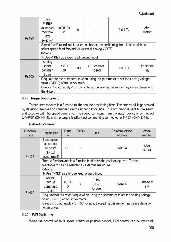
Adjustment
100
Pn123
Use V-REF
as speed feedforw
ard selection
0x00~0x01
0 - 0x0123 After
restart
Speed feedforward is a function to shorten the positioning time. It is possible to select speed feed forward via external analog V-REF. 0-None 1- Use V-REF as speed feed forward input
Pn300
Analog speed
command gain
150~3000
600 0.01V/Rated
speed 0x0300
Immediately
Required for the rated torque when using this parameter to set the analog voltage value (T-REF) of the servo motor. Caution: Do not apply -10~10V voltage. Exceeding this range may cause damage to the driver.
Torque Feedforward 6.6.4.
Torque feed forward is a function to shorten the positioning time. The command is generated by deviating the position command on the upper device side. This command is sent to the servo unit together with the speed command. The speed command from the upper device is connected to V-REF (CN1-5, 6), and the torque feedforward command is connected to T-REF (CN1-9, 10).
Related parameters
Function code
Parameter Rang
e Defau
lt Unit
Communication address
When enabled
Pn124
Speed/position control selection (T-REF
assignment)
0~1 0 - 0x0124 After
restart
Torque feed forward is a function to shorten the positioning time. Torque feedforward can be selected by external analog T-REF. 0-None 1- Use T-REF as a torque feed forward input
Pn405
Analog torque
command gain
10~100
30 0.1V/ Rated torque
0x0405 Immediat
ely
Required for the rated torque when using this parameter to set the analog voltage value (T-REF) of the servo motor. Caution: Do not apply -10~10V voltage. Exceeding this range may cause damage to the driver.
P/PI Switching 6.6.5.
When the control mode is speed control or position control, P/PI control can be switched.

Adjustment
101
When the control mode is mixed, it is valid only when it is switched to internal speed, analog speed and position mode. The P/PI switching can be switched by the binary signal manual P-PI control signal (/P-CON). When the /P-CON signal is turned ON, P control is performed. The conditions for selecting automatic switching can also be selected by the parameter speed loop P/PI switching condition selection switch Pn131.
Manual P-PI Control
Manual P-PI Control Configuration
The signal is not configured in the factory default switch configuration. Therefore, the pin number configuration (0x05) needs to be performed by parameters Pn601~Pn609.
Manual P-PI control wiring
The gain switching signal is a universally configurable digital input. See "Sequence Input Circuit" for wiring details.
Automatic switching
For automatic P/PI switching, the switching condition is set by Pn131, and the switching condition value is set by Pn132, Pn133, Pn134, and Pn135. By properly setting the switching conditions and condition values, overshoot during acceleration and deceleration can be suppressed and the settling time can be shortened.
Overshot
Feedback
CommandStable Time
Over-adjustment
Time Time
SpeedSpeed
Stable time
Function code
Parameter Range Default Unit Communication
address When
enabled
Pn131
Speed loop P/PI switching
condition selection
switch
0x00~0x04
0 - 0x0131 Immediately
The mode switch is a function that automatically performs P control and PI control switching. Setting the switching condition by this parameter and satisfying the corresponding switching condition value can suppress overshoot during acceleration and deceleration and shorten the settling time. 0 - Conditioned by internal torque command 1- Conditional speed instruction 2- Conditional acceleration 3- Conditional position deviation pulse 4-No mode switch function

Adjustment
102
Pn132
Speed loop P/PI switching
condition (torque
command)
0~800 200 % 0x0132 Immediately
When the torque command exceeds the torque set by this parameter, the speed loop will be switched to P control, otherwise PI control
Pn133
Speed loop P/PI switching condition (speed
command)
0~10000 0 rpm 0x0133 Immediately
When the speed command exceeds the speed set by this parameter, the speed loop will be switched to P control, otherwise PI control
Pn134
Speed loop P/PI switching conditions (accelerati
on)
0~30000 0 rpm/s 0x0134 Immediately
When the speed command exceeds the acceleration set by this parameter, the speed loop will be switched to P control, otherwise PI control
Pn135
Speed loop P/PI switching conditions (position deviation)
0~10000 0 Instruction
unit 0x0135 Immediately
When the position deviation exceeds the value set by this parameter, the speed loop will be switched to P control, otherwise PI control
When the switching condition of the mode switch is set as a torque command [factory setting], when the torque command exceeds the torque set in Pn10C, the speed loop will switch to P control. The factory torque command value is set to 200%.
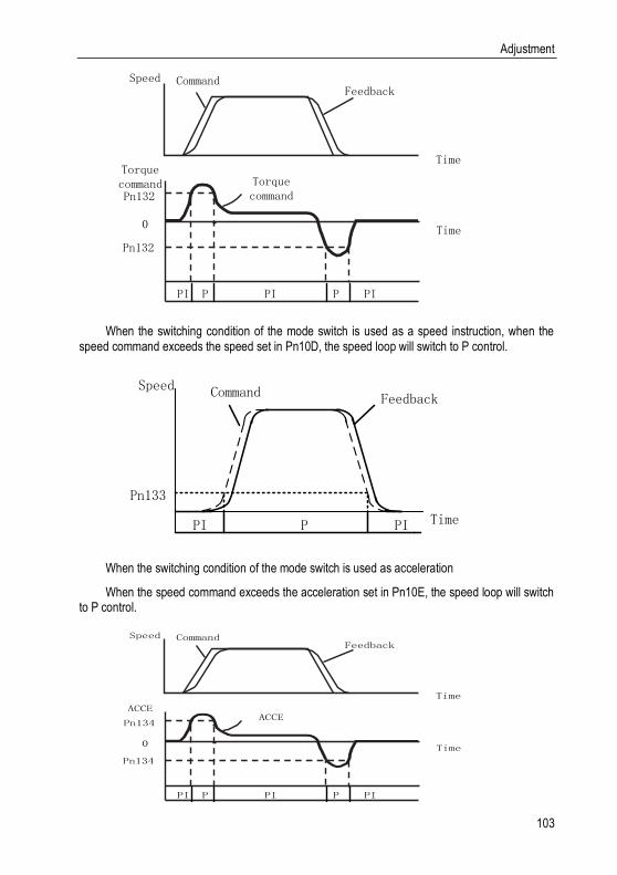
Adjustment
103
Speed CommandFeedback
Time
Torque command
Torque command
Time
Pn132
Pn132
PI P PI P PI
0
When the switching condition of the mode switch is used as a speed instruction, when the speed command exceeds the speed set in Pn10D, the speed loop will switch to P control.
Time
Speed Command Feedback
Pn133
PI P PI
When the switching condition of the mode switch is used as acceleration
When the speed command exceeds the acceleration set in Pn10E, the speed loop will switch to P control.
Speed CommandFeedback
Time
ACCEACCE
Time
Pn134
Pn134
PI P PI P PI
0

Adjustment
104
When the switching condition of the mode switch is set as the position deviation, when the position deviation exceeds the value set in Pn10F, the speed loop will switch to P control. This setting is valid only for position control.
Time
Position offset
Pn135
PI P PI
Speed CommandFeedback
Time

Accessibility
105
Accessibility 7.
List of Auxiliary FunctionsThe auxiliary function is displayed with a number starting 7.1.
with Fn, and functions related to the operation and adjustment of the servo motor are performed. The following table lists the auxiliary functions and reference items.
Auxiliary function number Function description
Fn 000 Display alarm record
Fn 001 Clear alarm record
Fn 002 Software reset
Fn 003 Restore factory parameters
Fn 005 JOG operation
Fn 006 Program JOG operation
Fn 100 Automatic adjustment of instruction offset
Fn 101 Speed command offset manual adjustment
Fn 102 Torque command offset manual adjustment
Fn 103 Current offset automatic adjustment
Fn 104 Current offset manual adjustment
Fn 105 Initialize the detected value of the vibration detection
Fn 303 Bandwidth setting
Fn 401 Easy FFT
Fn 402 Online vibration monitoring
Displaying Alarm Logs (Fn000) 7.2.
Overview 7.2.1.
The servo unit has a record alarm function and can record up to 10 alarms that have occurred. This auxiliary function allows you to confirm the number and time of the alarm (measurement of the duration of the control power supply and the main circuit power supply in 100ms increments, and the function to display the total operation time in the event of an alarm, if it is 365 days per year. it can last for about 31 years if you operating it 24 hours a day.)
Cautions! 1. When the same alarm occurs continuously, if the interval between alarms is less than
1 hour, it will not be saved. If it exceeds 1 hour, it will be saved.
2. When an alarm does not occur, “ ----” is displayed on the panel operator.
3, the alarm record can only be cleared by "clear alarm record (Fn001)".

Accessibility
106
Operating Procedure 7.2.2.
Latest alarm
Display alarm record
Old alarmAny interface
MODE/SETLong press
DATA/SHIFT Low alarm recording time
UP: 1 query
DOWN: 9 next
query
Long press
DATA/SHIFT
Short press
DATA/SHIFT
Alarm recording time median
Short press
DATA/SHIFTShort press
DATA/SHIFTAlarm recording time high
Short press
DATA/SHIFT
Long press
DATA/SHIFT
Old alarmAccessibi
lity
Accessibility
Clear Alarm Record (Fn001) 7.3.
Summary 7.3.1.
The alarm record of the servo unit can only be cleared by clearing the alarm record (Fn001) function. Alarm recording cannot be cleared by resetting the alarm or switching off the main circuit power of the servo unit.
Operating Procedure 7.3.2.
Clear alarm record
Accessibility
Alarm clear
Any interface
MODE/SET Clear confirmatio
n
Long press
DATA/SHIFT
Long press
DATA/SHIFT
Accessibility
UPMODE/SET
Flash 2s
Software Reset (Fn002) 7.4.
Summary 7.4.1.
The function of resetting the servo unit is from the inside by software. Used to re-power on or reset the alarm after changing the parameter setting. It is also possible to validate the setting without turning the power back on.
Cautions! 1. This function must be started with servo off.
2. This function has nothing to do with the upper device to reset the servo unit. Same as when the power
is turned on, the servo unit outputs the ALM signal, and other output signals may also be forcibly
changed.
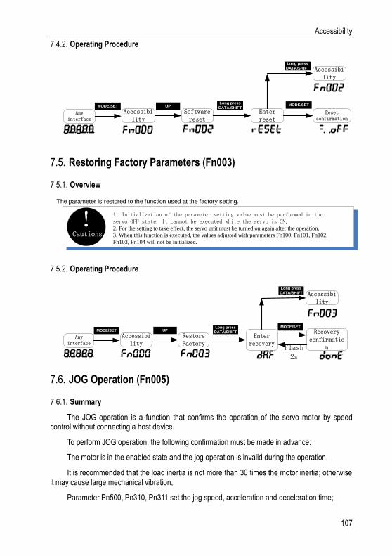
Accessibility
107
Operating Procedure 7.4.2.
Software reset
Accessibility
Enter reset
Any interface
MODE/SET
Reset confirmation
Long press
DATA/SHIFT
Long press
DATA/SHIFT
Accessibility
UP MODE/SET
Restoring Factory Parameters (Fn003) 7.5.
Overview 7.5.1.
The parameter is restored to the function used at the factory setting.
Cautions! 1. Initialization of the parameter setting value must be performed in the
servo OFF state. It cannot be executed while the servo is ON.2. For the setting to take effect, the servo unit must be turned on again after the operation.
3. When this function is executed, the values adjusted with parameters Fn100, Fn101, Fn102,
Fn103, Fn104 will not be initialized.
Operating Procedure 7.5.2.
Restore Factory
Accessibility
Enter recovery
Any interface
MODE/SET Recovery confirmatio
n
Long press
DATA/SHIFT
Long press
DATA/SHIFT
Accessibility
UPMODE/SET
Flash 2s
JOG Operation (Fn005) 7.6.
Summary 7.6.1.
The JOG operation is a function that confirms the operation of the servo motor by speed control without connecting a host device.
To perform JOG operation, the following confirmation must be made in advance:
The motor is in the enabled state and the jog operation is invalid during the operation.
It is recommended that the load inertia is not more than 30 times the motor inertia; otherwise it may cause large mechanical vibration;
Parameter Pn500, Pn310, Pn311 set the jog speed, acceleration and deceleration time;
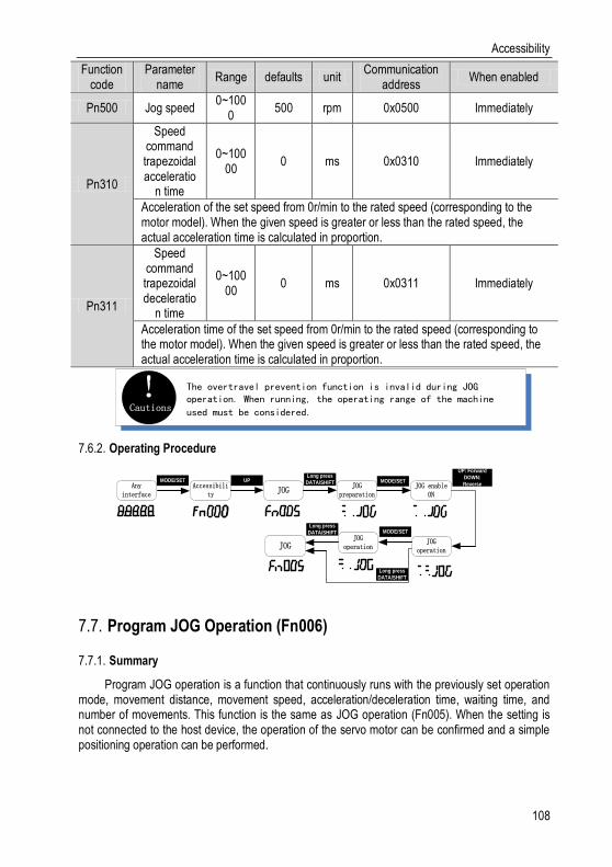
Accessibility
108
Function code
Parameter name
Range defaults unit Communication
address When enabled
Pn500 Jog speed 0~100
0 500 rpm 0x0500 Immediately
Pn310
Speed command trapezoidal acceleratio
n time
0~10000
0 ms 0x0310 Immediately
Acceleration of the set speed from 0r/min to the rated speed (corresponding to the motor model). When the given speed is greater or less than the rated speed, the actual acceleration time is calculated in proportion.
Pn311
Speed command trapezoidal deceleratio
n time
0~10000
0 ms 0x0311 Immediately
Acceleration time of the set speed from 0r/min to the rated speed (corresponding to the motor model). When the given speed is greater or less than the rated speed, the actual acceleration time is calculated in proportion.
Cautions! The overtravel prevention function is invalid during JOG
operation. When running, the operating range of the machine
used must be considered.
Operating Procedure 7.6.2.
JOGAccessibili
tyJOG
preparationAny
interface
MODE/SET UPLong press
DATA/SHIFTJOG enable
ON
MODE/SET
UP: Forward
DOWN:
Reverse
JOG operation
JOG operationJOG
MODE/SETLong press
DATA/SHIFT
Long press
DATA/SHIFT
Program JOG Operation (Fn006) 7.7.
Summary 7.7.1.
Program JOG operation is a function that continuously runs with the previously set operation mode, movement distance, movement speed, acceleration/deceleration time, waiting time, and number of movements. This function is the same as JOG operation (Fn005). When the setting is not connected to the host device, the operation of the servo motor can be confirmed and a simple positioning operation can be performed.

Accessibility
109
Cautions! 1. Program JOG operation is position control, gear ratio and position command filtering
are valid, but pulse instructions cannot be input to the servo unit.
2. The overtravel prevention function takes effect.
Operating Procedure 7.7.2.
Program JOG
Accessibility
Program JOG preparation
Any interface
MODE/SET UPLong press
DATA/SHIFT
Enabled ON
MODE/SET
In the
setting
direction
UP/DOWN
working process
Program JOG preparationJOG
MODE/SETLong press
DATA/SHIFT
Long press
DATA/SHIFT
End of operation
Automatic Adjustment of Instruction Offset (Fn100) 7.8.
Summary 7.8.1.
The automatic adjustment command offset is a method of automatically adjusting the command voltage after measuring the offset amount. The measured offset will be stored in the servo unit.
Cautions! 1, the servo is OFF
2. Offset adjustment overrange or input voltage instruction during offset adjustment may
fail to adjust
Operating Procedure 7.8.2.
Turn off the servo drive and input the 0V command voltage from the host device or external circuit.
Automatic offset
adjustment
Accessibility
Enter automatic adjustment
Any interface
MODE/SET
Adjustment confirmation
Long press
DATA/SHIFT
Long press
DATA/SHIFT
Accessibility
UPMODE/SET
Flash2s
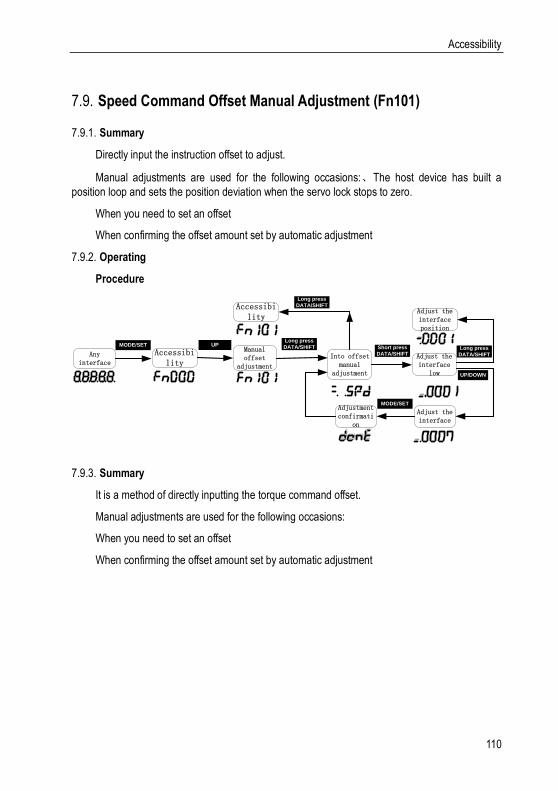
Accessibility
110
Speed Command Offset Manual Adjustment (Fn101) 7.9.
Summary 7.9.1.
Directly input the instruction offset to adjust.
Manual adjustments are used for the following occasions:、The host device has built a
position loop and sets the position deviation when the servo lock stops to zero.
When you need to set an offset
When confirming the offset amount set by automatic adjustment
Operating 7.9.2.
Procedure
Manual offset
adjustment
Accessibility
Into offset manual
adjustment
Any interface
MODE/SET
Adjust the interface
low
Long press
DATA/SHIFT
Long press
DATA/SHIFT
Accessibility
UPShort press
DATA/SHIFT
Adjust the interface
UP/DOWN
MODE/SETAdjustment confirmati
on
Adjust the interface position
Long press
DATA/SHIFT
Summary 7.9.3.
It is a method of directly inputting the torque command offset.
Manual adjustments are used for the following occasions:
When you need to set an offset
When confirming the offset amount set by automatic adjustment
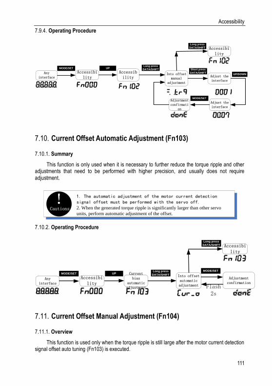
Accessibility
111
Operating Procedure 7.9.4.
Accessibility
Accessibility
Into offset manual
adjustment
Any interface
MODE/SET
Adjust the interface
Long press
DATA/SHIFT
Long press
DATA/SHIFT
Accessibility
UPShort press
DATA/SHIFT
Adjust the interface
UP/DOWN
MODE/SETAdjustment confirmati
on
Current Offset Automatic Adjustment (Fn103) 7.10.
Summary 7.10.1.
This function is only used when it is necessary to further reduce the torque ripple and other adjustments that need to be performed with higher precision, and usually does not require adjustment.
Cautions! 1. The automatic adjustment of the motor current detection
signal offset must be performed with the servo off.2. When the generated torque ripple is significantly larger than other servo
units, perform automatic adjustment of the offset.
Operating Procedure 7.10.2.
Current bias
automatic adjustment
Accessibility
Into offset automatic adjustment
Any interface
MODE/SET
Adjustment confirmation
Long press
DATA/SHIFT
Long press
DATA/SHIFT
Accessibility
UPMODE/SET
Flash2s
Current Offset Manual Adjustment (Fn104) 7.11.
Overview 7.11.1.
This function is used only when the torque ripple is still large after the motor current detection signal offset auto tuning (Fn103) is executed.
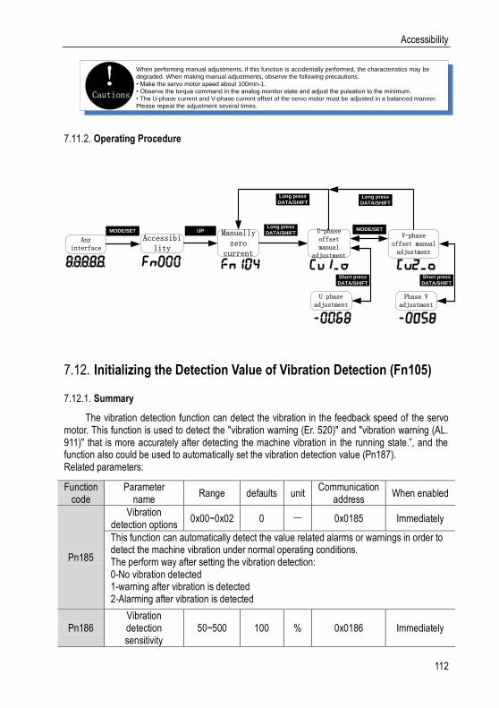
Accessibility
112
Cautions!
When performing manual adjustments, if this function is accidentally performed, the characteristics may be
degraded. When making manual adjustments, observe the following precautions.
• Make the servo motor speed about 100min-1.
• Observe the torque command in the analog monitor state and adjust the pulsation to the minimum.
• The U-phase current and V-phase current offset of the servo motor must be adjusted in a balanced manner.
Please repeat the adjustment several times.
Operating Procedure 7.11.2.
Manually zero
current
Accessibility
U-phase offset manual
adjustment
Any interface
MODE/SETV-phase
offset manual adjustment
Long press
DATA/SHIFT
Long press
DATA/SHIFTUP MODE/SET
Long press
DATA/SHIFT
Short press
DATA/SHIFT
U phase adjustment
Short press
DATA/SHIFT
Phase V adjustment
Initializing the Detection Value of Vibration Detection (Fn105) 7.12.
Summary 7.12.1.
The vibration detection function can detect the vibration in the feedback speed of the servo motor. This function is used to detect the "vibration warning (Er. 520)" and "vibration warning (AL. 911)" that is more accurately after detecting the machine vibration in the running state.”, and the function also could be used to automatically set the vibration detection value (Pn187). Related parameters:
Function code
Parameter name
Range defaults unit Communication
address When enabled
Pn185
Vibration detection options
0x00~0x02 0 - 0x0185 Immediately
This function can automatically detect the value related alarms or warnings in order to detect the machine vibration under normal operating conditions. The perform way after setting the vibration detection: 0-No vibration detected 1-warning after vibration is detected 2-Alarming after vibration is detected
Pn186 Vibration detection sensitivity
50~500 100 % 0x0186 Immediately
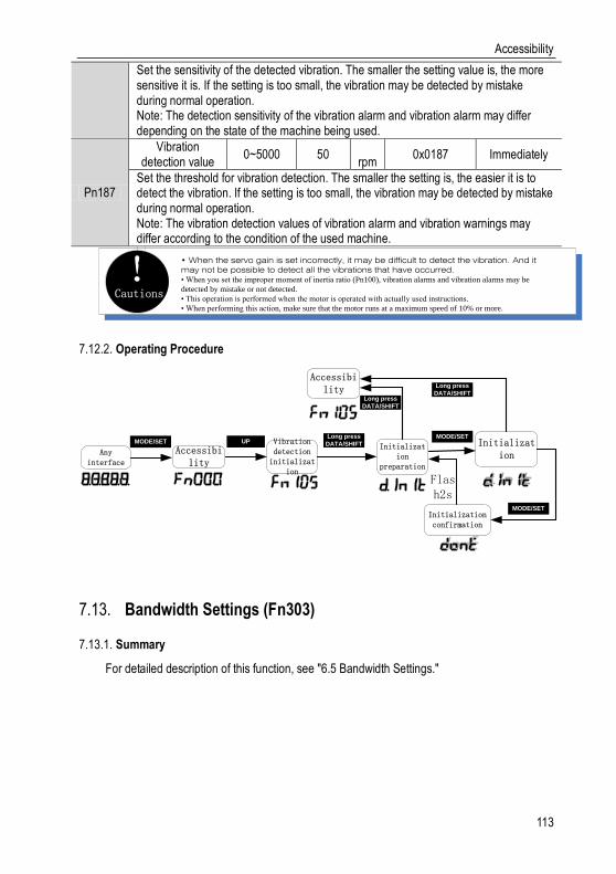
Accessibility
113
Set the sensitivity of the detected vibration. The smaller the setting value is, the more sensitive it is. If the setting is too small, the vibration may be detected by mistake during normal operation. Note: The detection sensitivity of the vibration alarm and vibration alarm may differ depending on the state of the machine being used.
Pn187
Vibration detection value
0~5000 50 rpm
0x0187 Immediately
Set the threshold for vibration detection. The smaller the setting is, the easier it is to detect the vibration. If the setting is too small, the vibration may be detected by mistake during normal operation. Note: The vibration detection values of vibration alarm and vibration warnings may differ according to the condition of the used machine.
Cautions!
• When the servo gain is set incorrectly, it may be difficult to detect the vibration. And it may not be possible to detect all the vibrations that have occurred.• When you set the improper moment of inertia ratio (Pn100), vibration alarms and vibration alarms may be
detected by mistake or not detected.
• This operation is performed when the motor is operated with actually used instructions.
• When performing this action, make sure that the motor runs at a maximum speed of 10% or more.
Operating Procedure 7.12.2.
Vibration detection
initialization
Accessibility
Initialization
preparation
Any interface
MODE/SET Initialization
Long press
DATA/SHIFT
Accessibility
UPMODE/SET
Long press
DATA/SHIFT
Initialization confirmation
Long press
DATA/SHIFT
MODE/SET
Flash2s
Bandwidth Settings (Fn303) 7.13.
Summary 7.13.1.
For detailed description of this function, see "6.5 Bandwidth Settings."
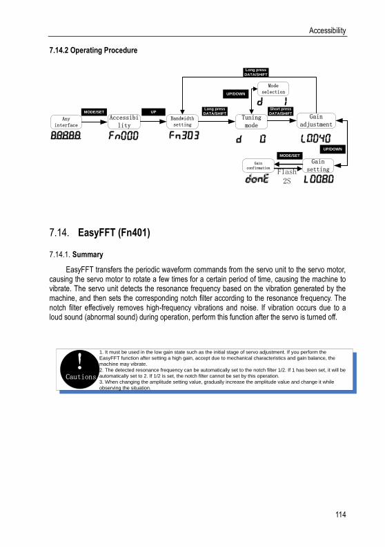
Accessibility
114
7.14.2 Operating Procedure
Bandwidth setting
Accessibility
Tuning mode
Any interface
MODE/SET
Gain adjustment
Long press
DATA/SHIFTUP
Long press
DATA/SHIFT
UP/DOWN
Gain setting
Mode selection
UP/DOWN
MODE/SET
Gain confirmation
Flash2S
Short press
DATA/SHIFT
EasyFFT (Fn401) 7.14.
Summary 7.14.1.
EasyFFT transfers the periodic waveform commands from the servo unit to the servo motor, causing the servo motor to rotate a few times for a certain period of time, causing the machine to vibrate. The servo unit detects the resonance frequency based on the vibration generated by the machine, and then sets the corresponding notch filter according to the resonance frequency. The notch filter effectively removes high-frequency vibrations and noise. If vibration occurs due to a loud sound (abnormal sound) during operation, perform this function after the servo is turned off.
Cautions!
1. It must be used in the low gain state such as the initial stage of servo adjustment. If you perform the
EasyFFT function after setting a high gain, accept due to mechanical characteristics and gain balance, the
machine may vibrate.
2. The detected resonance frequency can be automatically set to the notch filter 1/2. If 1 has been set, it will be
automatically set to 2. If 1/2 is set, the notch filter cannot be set by this operation.
3. When changing the amplitude setting value, gradually increase the amplitude value and change it while
observing the situation.

Accessibility
115
Operating Procedure 7.14.2.
EasyFFTAccessibi
lityAmplitude setting
Any interface
MODE/SET
Ready state
Long press
DATA/SHIFTUP
Long press
DATA/SHIFTUP/DOWN
Operating status
Amplitude setting
MODE/SET
Checkout processFlash
2S
Long press
DATA/SHIFT
MODE/SET
UP/DOWN
Checkout result
Confirmation of results
MODE/SET
Flash2S
Long press
DATA/SHIFT
Online Vibration Monitoring (Fn402) 7.15.
Overview 7.15.1.
When the servo is ON and vibration occurs during operation, this operation can set the notch filter 1 or the torque command filter according to the vibration frequency, sometimes eliminating the vibration. The vibration frequency of the noise generated by the mechanical resonance or the like is detected, and the frequency of the large-peak vibration is displayed on the manipulator. For this frequency, an effective torque command filter or notch filter 1 frequency is automatically selected and related parameters are automatically set. When using the upper computer debugging software to adjust, it is recommended to perform the smart setting or bandwidth setting. Generally, no manual operation is required. Only if the upper level debugging software is not used, it is key-assisted.
Operating Procedure 7.15.2.
Vibration monitoring
Accessibility
Monitoring preparation
Any interface
MODE/SET V phase offset manual
adjustment
Long press
DATA/SHIFT
Long press
DATA/SHIFTUP MODE/SET
Long press
DATA/SHIFT
Monitoring results
Monitoring failed
MODE/SET
confirm
Long press
DATA/SHIFT
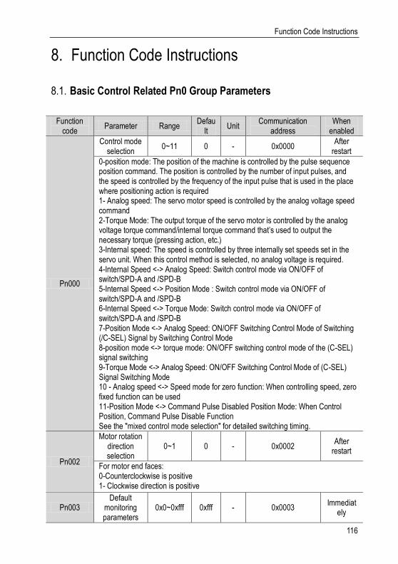
Function Code Instructions
116
Function Code Instructions 8.
Basic Control Related Pn0 Group Parameters 8.1.
Function code
Parameter Range Defau
lt Unit
Communication address
When enabled
Pn000
Control mode selection
0~11 0 - 0x0000 After
restart
0-position mode: The position of the machine is controlled by the pulse sequence position command. The position is controlled by the number of input pulses, and the speed is controlled by the frequency of the input pulse that is used in the place where positioning action is required 1- Analog speed: The servo motor speed is controlled by the analog voltage speed command 2-Torque Mode: The output torque of the servo motor is controlled by the analog voltage torque command/internal torque command that’s used to output the necessary torque (pressing action, etc.) 3-Internal speed: The speed is controlled by three internally set speeds set in the servo unit. When this control method is selected, no analog voltage is required. 4-Internal Speed <-> Analog Speed: Switch control mode via ON/OFF of switch/SPD-A and /SPD-B 5-Internal Speed <-> Position Mode : Switch control mode via ON/OFF of switch/SPD-A and /SPD-B 6-Internal Speed <-> Torque Mode: Switch control mode via ON/OFF of switch/SPD-A and /SPD-B 7-Position Mode <-> Analog Speed: ON/OFF Switching Control Mode of Switching (/C-SEL) Signal by Switching Control Mode 8-position mode <-> torque mode: ON/OFF switching control mode of the (C-SEL) signal switching 9-Torque Mode <-> Analog Speed: ON/OFF Switching Control Mode of (C-SEL) Signal Switching Mode 10 - Analog speed <-> Speed mode for zero function: When controlling speed, zero fixed function can be used 11-Position Mode <-> Command Pulse Disabled Position Mode: When Control Position, Command Pulse Disable Function See the "mixed control mode selection" for detailed switching timing.
Pn002
Motor rotation direction selection
0~1 0 - 0x0002 After
restart
For motor end faces: 0-Counterclockwise is positive 1- Clockwise direction is positive
Pn003 Default
monitoring parameters
0x0~0xfff 0xfff - 0x0003 Immediat
ely
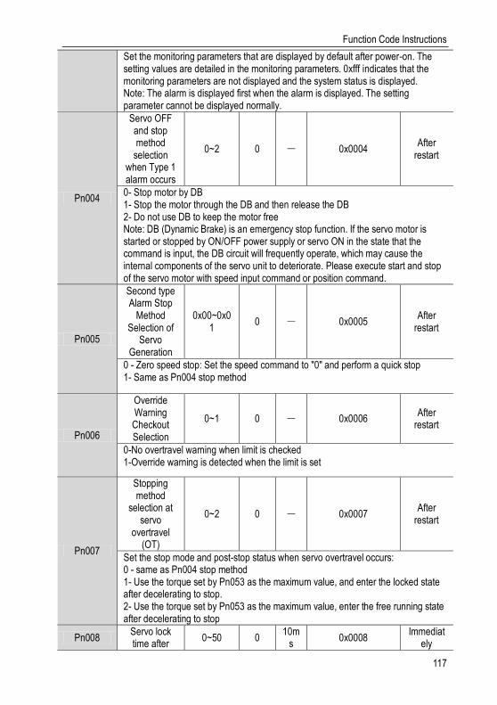
Function Code Instructions
117
Set the monitoring parameters that are displayed by default after power-on. The setting values are detailed in the monitoring parameters. 0xfff indicates that the monitoring parameters are not displayed and the system status is displayed. Note: The alarm is displayed first when the alarm is displayed. The setting parameter cannot be displayed normally.
Pn004
Servo OFF and stop method
selection when Type 1 alarm occurs
0~2 0 - 0x0004 After
restart
0- Stop motor by DB 1- Stop the motor through the DB and then release the DB 2- Do not use DB to keep the motor free Note: DB (Dynamic Brake) is an emergency stop function. If the servo motor is started or stopped by ON/OFF power supply or servo ON in the state that the command is input, the DB circuit will frequently operate, which may cause the internal components of the servo unit to deteriorate. Please execute start and stop of the servo motor with speed input command or position command.
Pn005
Second type Alarm Stop
Method Selection of
Servo Generation
0x00~0x01
0 - 0x0005 After
restart
0 - Zero speed stop: Set the speed command to "0" and perform a quick stop 1- Same as Pn004 stop method
Pn006
Override Warning Checkout Selection
0~1 0 - 0x0006 After
restart
0-No overtravel warning when limit is checked 1-Override warning is detected when the limit is set
Pn007
Stopping method
selection at servo
overtravel (OT)
0~2 0 - 0x0007 After
restart
Set the stop mode and post-stop status when servo overtravel occurs: 0 - same as Pn004 stop method 1- Use the torque set by Pn053 as the maximum value, and enter the locked state after decelerating to stop. 2- Use the torque set by Pn053 as the maximum value, enter the free running state after decelerating to stop
Pn008 Servo lock time after
0~50 0 10m
s 0x0008
Immediately

Function Code Instructions
118
electromagnetic brake holding
When the servo motor is enabled but not running and the brake (/BK) signal and the servo ON (/S-ON) signal are off at the same time, setting this parameter can change the non-powered time from the brake (/BK) signal OFF to the actual input of the motor. Note: The brake delay time is slightly different. When this parameter is set, the motor can be prevented from the slight moving by the weight or the external force of the vertical-axis mechanical movement.
Pn009
Electromagnetic brake
holding time delay
10~100 50 10m
s 0x0009
Immediately
The servo motor won’t be electrified when the Servo OFF/Alarm/Main circuit OFF occur during the rotation. By setting this parameter and Pn010 (any one is met), the output timing of the brake signal (/BK) OFF can be adjusted. Note: The relevant logic is described in "Keep brake action"
Pn010
Electromagnetic brake
brake delay release speed
0~10000 100
rpm
0x0010 Immediat
ely
See the description of “Electromagnetic brake brake delay” for details
Pn012
External regenerative
resistor power
0~65535 0 10W 0x0012 Immediat
ely
When connecting an external regenerative resistor, the regenerative resistor power should be set to a value that matches the allowable capacity of the connected external regenerative resistor. The setting differs depending on the cooling condition of the external regenerative resistor. Note: Refer to "Setting the regenerative resistor" for details
Pn013
External regenerative
resistor 0~65535 0 mΩ 0x0013
Immediately
When connecting an external regenerative resistor, the regenerative resistor value should be set to the value matching the connected external regenerative resistor. Note: The minimum regenerative resistance of each power section could be different. Please refer to “Set regenerative resistor” for details. Otherwise, the internal components of the servo unit may be damaged.
Pn015
Overload warning value
1~100 20 % 0x0015 After
restart
Setting this parameter can change the overload warning detection time. For example, the factory overload warning detection time is 20% of the overload warning detection time. Note: The overload alarm detection time is detailed in "Overload alarm"

Function Code Instructions
119
Pn016
Motor overload detection
base current derating setting
10~100 100 % 0x0016 After
restart
This parameter can change the motor current threshold for calculating the overload alarm, which can shorten the overload alarm detection time. Note: This value is invalid when the motor current is rated above 200%.
Pn030 Reserved 0~65535 0 - 0x0030 Immediat
ely
Pn031
Parameter modification
operation lock
0~1 0 - 0x0031 After
restart
0-allow panel parameters modification 1-prohibit panel parameters modification
Pn040
Method to use absolute
encoder 0~1 0 - 0x0040
After restart
0 - Use an absolute encoder as an absolute encoder: If the motor is an absolute multi-turn encoder, setting this parameter to 1 can use the multi-turn absolute function 1- Use an absolute encoder as an incremental encoder: When used as an incremental encoder, the power-off position won’t be recorded and warning or alarm, corresponding to multiple revolutions, won’t happen either when the battery is undervoltage or the drive is de-energized
Pn041
Absolute encoder battery
warning/warning selection
0~1 0 - 0x0041 After
restart
0- Set the low battery voltage as a fault: The driver powers up/resets for 4~9 seconds to monitor the battery status. Undervoltage will be reported as an under voltage alarm (Er. 830). Over time will not be detected. 1- Set the low battery voltage as a warning: Undervoltage (below 3V) will be reported as an under voltage alarm (Al.930). It will always monitor the battery voltage and can be self-recovery meanwhile enable running is out of restriction
Pn045
Undervoltage function selection
0x00~0x02
0 - 0x0045 After
restart
0 – No Detection of Main Circuit Descent Warning 1- Detection of Main Circuit Descent Warning 2 - Detect main circuit down warning and perform torque limit. The relevant torque limit is matched with Pn046/Pn047. For details, refer to "Main circuit undervoltage torque limit".
Pn046 Torque limit 0~100 50 % 0x0046 Immediat

Function Code Instructions
120
when main circuit voltage
drops
ely
According to the under voltage warning, it will impose the torque limit inside the servo unit. For details, see the "Torque limit under voltage" instruction.
Pn047
Torque limit release time when main
circuit voltage drops
0~1000 100 ms 0x0047 Immediat
ely
After the under-voltage warning signal releases, the torque limit value is controlled within the servo unit according to the set time. For details, see “Under-voltage limit of the main circuit”.
Pn050
Torque limit setting
0~3 1 - 0x0050 Immediat
ely
0 - Analog torque (torque mode is invalid) 1- maximum torque limit is 1 2- maximum Forward torque limit is 1 and maximum Reverse torque limit is 2 3- Maximum torque limit is 1 when the "Torque Limit Switching" switch is OFF while Maximum torque limit is 2 when it’s ON
Pn051 Maximum
torque limit 1 0~500 500 % 0x0051
Immediately
Pn052 Maximum
torque limit 2 0~500 500 % 0x0052
Immediately
Pn053 Emergency stop torque
0~800 800 % 0x0053 Immediat
ely
The torque when set the motor stop method to deceleration stop.
Pn061
Panel parameter
display selection
0x00~0x01
1 - 0x0061 After
restart
0- Only display setting parameters 1- Show all parameters
Pn070
Encoder divider pulses
16~4194304
2048 - 0x0070 After
restart
The number of pulses per cycle from the encoder is divided by frequency in accordance with the set value of this parameter. Please set it according to the system specifications of the machine and host device. Note: The set value is the number of A/B quadrature output pulses in one turn. The setting of the number of encoder crossover pulses will be limited due to the resolution of the encoder. For details, see the “Divided pulse output setting” instruction.
Pn072
negate the divide
frequency output
0~1 0 - 0x0072 After
restart

Function Code Instructions
121
A/B pulse phase sequence logic when setting forward/reverse: 0- Don’t negate the pulse output: When forward, A is ahead of B 1- Negate the pulse output: When forward, B is ahead of A
Pn080 Local
communication address
0x00~0x7F
1 - 0x0080 After
restart
Pn081
485 communication baud rate
selection
0~4 1 - 0x0081 After
restart
0-9600bps 1-19200bps 2-38400bps 3-57600bps 4-115200bps
Pn082
485 communication verification
method
0~5 1 - 0x0082 After
restart
0-no parity (N,8,1) 1-even parity (E,8,1) 2-odd check (O,8,1) 3-no check (N,8,2) 4-Even Check (E,8,2) 5-Odd Check (O,8,2)
Gain Related Pn1 Group 8.2.
Function code
Parameter Range
Default
Unit Communicatio
n address When
enabled
Pn100
Rotary inertia ratio 0~200
00 100 % 0x0100
Immediately
Rotary inertia ratio = load inertia of motor shaft conversion / rotor rotary inertia of servo motor *100%
Pn101
First speed gain 1~200
0 40.0 Hz 0x0101
Immediately
Determine the parameters of the speed loop responsiveness. It becomes a delay element of the outer position loop when the response of the speed loop is low, so overshoot or vibration of the speed command occurs. In the range where the mechanical system does not vibrate, the larger the value is set, the more stable the servo system becomes and the better the responsiveness will be.
Pn102
First speed integration time constant
0.15~512
20.00 ms 0x0102 Immedia
tely
In order to respond to small input, the speed loop contains integral elements. Since this integral element is a delay factor for the servo system, when the time parameter is set too large, overshoot may occur, or the positioning time may be extended meanwhile resulting in poor responsiveness.
Pn103 First position gain 1~200 40.0 1/s 0x0103 Immedia

Function Code Instructions
122
0 tely
The position loop response is determined by the position loop gain. The higher the setting of the position loop gain is, the higher the responsiveness and the shorter the positioning time will be. The position loop gain cannot be increased beyond the rigidity of the mechanical system. To increase the position loop gain to a larger value, the rigidity of the machine must be increased.
Pn104
First torque command filter 0~655.
35 1.00 ms 0x0104
Immediately
Adjusting the parameters of the torque command filter may eliminate the machine vibration caused by the servo drive. The smaller the value is, the better the responsiveness can be. However, the conditions are restricted by the machine conditions.
Pn105
Second speed gain 1~200
0 40.0 Hz 0x0105
Immediately
Determine the parameters of the speed loop responsiveness. It becomes a delay element of the outer position loop when the response of the speed loop is low, so overshoot or vibration of the speed command occurs. In the range where the mechanical system does not vibrate, the larger the value is set, the more stable the servo system becomes and the better the responsiveness will be
Pn106
The second speed integration time constant
0.15~512
20.00 ms 0x0106 Immedia
tely
In order to respond to small input, the speed loop contains integral elements. Since this integral element is a delay factor for the servo system, when the time parameter is set too large, overshoot may occur, or the positioning time may be extended meanwhile resulting in poor responsiveness.
Pn107
Second position gain 1~200
0 40.0 1/s 0x0107
Immediately
The position loop response is determined by the position loop gain. The higher the setting of the position loop gain is, the higher the responsiveness and the shorter the positioning time will be. The position loop gain cannot be increased beyond the rigidity of the mechanical system. To increase the position loop gain to a larger value, the rigidity of the machine must be increased.
Pn108
Second torque command filter 0~655.
35 1.00 ms 0x0108
Immediately
Adjusting the parameters of the torque command filter may eliminate the machine vibration caused by the servo drive. The smaller the value is, the better the responsiveness can be. However, the conditions are restricted by the machine conditions.
Pn110
Gain switching mode selection switch
0x00~0x01
0 - 0x0110 Immedia
tely
The gain switching function includes two methods of “manual gain switching” using an external input signal and “automatic gain switching” automatically switching. By using the gain switching function, gain can be increased and positioning time can be shortened during the positioning time. When the motor is stopped. Reduce gain and suppress vibration. 0- Manual Gain Switching of the External Input Signal (G-SEL) 1- When the automatic switching condition is met (Pn111), it automatically switches from the first gain to the second gain; otherwise, it switches back to the first gain.
Pn111 automatic switching condition of
position control gain 0x00~0x05
0 - 0x0111 Immedia
tely

Function Code Instructions
123
Set the conditions for automatic gain switching: 0-positioning completion signal ON 1-Positioning completion signal OFF 2-positioning proximity signal ON 3- positioning proximity signal OFF 4- position command is 0 after filtering and pulse input is OFF 5- position command pulse input is ON If the conditions are met, then switch to the second gain, otherwise switch to the first gain
Pn112
Gain switching transition time 1 0~655
35 0 ms 0x0112
Immediately
After finish the Waiting Time from the time when the switching condition has been met, the gain of the first position loop is changed linearly to the gain of the second position loop in the transition time.
Pn113
Gain switching transition time 2 0~655
35 0 ms 0x0113
Immediately
After finish the Waiting Time from the time when the switching condition has been met, the gain of the second position loop is changed linearly to the gain of the first position loop in the transition time.
Pn114
Gain switching wait time 1 0~655
35 0 ms 0x0114
Immediately
The time from when switching condition is established from the first gain to the second gain to when the switching is actually started
Pn115
Gain switching wait time 2 0~655
35 0 ms 0x0115
Immediately
The time from when switching condition is established from the second gain to the first gain to when the switching is actually started
Pn121
Speed feedforward gain 0~100 0 % 0x0121 Immedia
tely
The time from when switching condition is established from the second gain to the first gain to when the switching is actually started
Pn122
Speed feedforward filter time 0~64 0.00 ms 0x0122 Immedia
tely
Speed feedforward low-pass filter time constant can slow position overshoot and torque jump caused by feedforward
Pn123
Use V-REF as speed feedforward selection
0x00~0x01
0 - 0x0123 After
restart
Speed feedforward is a function to shorten the positioning time. It is possible to select speed feed forward via external analog V-REF. 0-None 1- Use V-REF as speed feed forward input
Pn124 Speed/position control selection
(T-REF assignment) 0~1 0 - 0x0124
After restart

Function Code Instructions
124
Torque feedforward is a function to shorten the positioning time. Torque feedforward can be selected by external analog T-REF. 0-None 1- Use T-REF as a torque feed forward input
Pn130
Speed loop control method (PI/IP) 0~1 0 - 0x0130 After
restart
0-PI control 1-I-P control
Pn131
Speed loop P/PI switching condition selection switch
0x00~0x04
0 - 0x0131 Immedia
tely
The mode switch is a function that automatically switches P control and PI control. Through setting the switching condition by this parameter and meeting the corresponding switching condition value can suppress overshoot during acceleration and deceleration and shorten the settling time. 0- Conditioned by internal torque command 1- Conditioned by speed instruction 2- Conditioned by acceleration 3- Conditioned by position deviation pulse 4-No mode switch function
Pn132
Speed loop P/PI switching condition (torque command)
0~800 200 % 0x0132 Immedia
tely
When the torque command exceeds the torque set by this parameter, the speed loop will be switched to P control, otherwise PI control
Pn133
Speed loop P/PI switching condition (speed command)
0~10000
0 rpm
0x0133 Immedia
tely
When the speed command exceeds the speed set by this parameter, the speed loop will be switched to P control, otherwise PI control
Pn134
Speed loop P/PI switching conditions (acceleration)
0~30000
0 rpm/s
0x0134 Immedia
tely
When the speed command exceeds the acceleration set by this parameter, the speed loop will be switched to P control, otherwise PI control
Pn135
Speed loop P/PI switching conditions (position deviation)
0~10000
0 指令
单位 0x0135
Immediately
When the position deviation exceeds the value set by this parameter, the speed loop will be switched to P control, otherwise PI control
Pn140
IF suppression control options 0x00~0x11
0x0010
- 0x0140 Immedia
tely
The IF suppression control function effectively suppresses the continuous vibration of about 100 to 1000 Hz that occurs when the control gain is increased. 0x1#: Automatic setting of IF suppression frequency through intelligent setting and bandwidth setting 0x0#: Not set by intelligent setting, bandwidth setting, only manual setting 0x#1: IF suppression frequency setting is valid 0x#0: IF suppression frequency setting is invalid
Pn142 IF suppression frequency 1~300
0 100.0 Hz 0x0142
Immediately
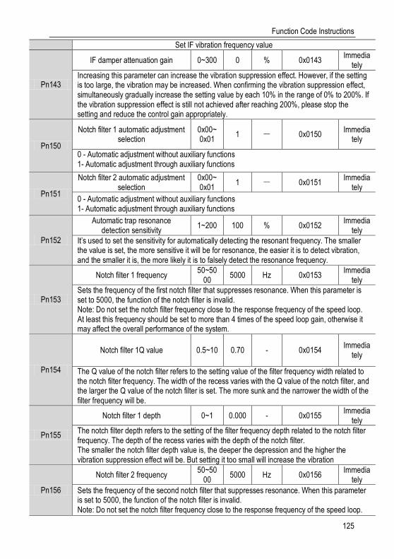
Function Code Instructions
125
Set IF vibration frequency value
Pn143
IF damper attenuation gain 0~300 0 % 0x0143 Immedia
tely
Increasing this parameter can increase the vibration suppression effect. However, if the setting is too large, the vibration may be increased. When confirming the vibration suppression effect, simultaneously gradually increase the setting value by each 10% in the range of 0% to 200%. If the vibration suppression effect is still not achieved after reaching 200%, please stop the setting and reduce the control gain appropriately.
Pn150
Notch filter 1 automatic adjustment selection
0x00~0x01
1 - 0x0150 Immedia
tely
0 - Automatic adjustment without auxiliary functions 1- Automatic adjustment through auxiliary functions
Pn151
Notch filter 2 automatic adjustment selection
0x00~0x01
1 - 0x0151 Immedia
tely
0 - Automatic adjustment without auxiliary functions 1- Automatic adjustment through auxiliary functions
Pn152
Automatic trap resonance detection sensitivity
1~200 100 % 0x0152 Immedia
tely
It’s used to set the sensitivity for automatically detecting the resonant frequency. The smaller the value is set, the more sensitive it will be for resonance, the easier it is to detect vibration, and the smaller it is, the more likely it is to falsely detect the resonance frequency.
Pn153
Notch filter 1 frequency 50~50
00 5000 Hz 0x0153
Immediately
Sets the frequency of the first notch filter that suppresses resonance. When this parameter is set to 5000, the function of the notch filter is invalid. Note: Do not set the notch filter frequency close to the response frequency of the speed loop. At least this frequency should be set to more than 4 times of the speed loop gain, otherwise it may affect the overall performance of the system.
Pn154
Notch filter 1Q value 0.5~10 0.70 - 0x0154 Immedia
tely
The Q value of the notch filter refers to the setting value of the filter frequency width related to the notch filter frequency. The width of the recess varies with the Q value of the notch filter, and the larger the Q value of the notch filter is set. The more sunk and the narrower the width of the filter frequency will be.
Pn155
Notch filter 1 depth 0~1 0.000 - 0x0155 Immedia
tely
The notch filter depth refers to the setting of the filter frequency depth related to the notch filter frequency. The depth of the recess varies with the depth of the notch filter. The smaller the notch filter depth value is, the deeper the depression and the higher the vibration suppression effect will be. But setting it too small will increase the vibration
Pn156
Notch filter 2 frequency 50~50
00 5000 Hz 0x0156
Immediately
Sets the frequency of the second notch filter that suppresses resonance. When this parameter is set to 5000, the function of the notch filter is invalid. Note: Do not set the notch filter frequency close to the response frequency of the speed loop.
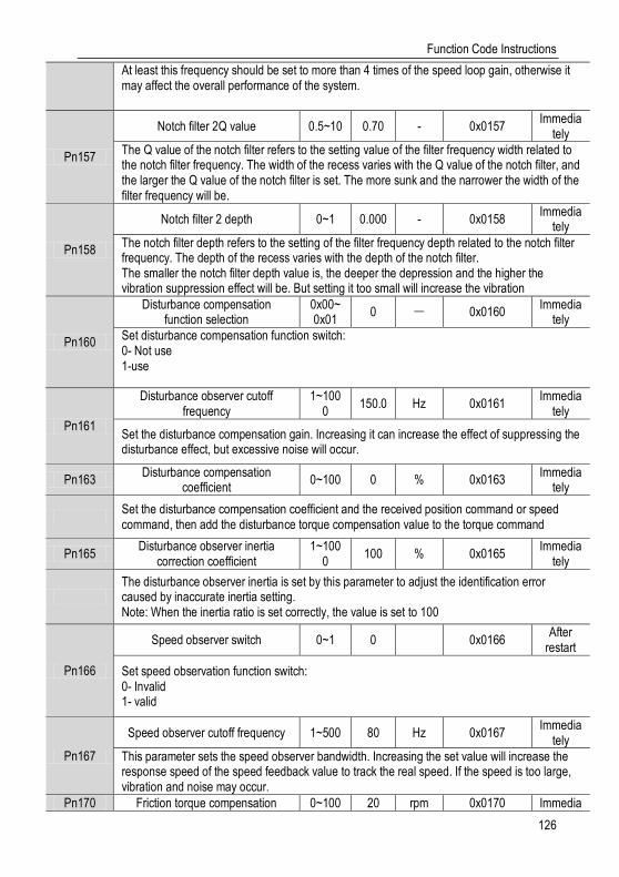
Function Code Instructions
126
At least this frequency should be set to more than 4 times of the speed loop gain, otherwise it may affect the overall performance of the system.
Pn157
Notch filter 2Q value 0.5~10 0.70 - 0x0157 Immedia
tely
The Q value of the notch filter refers to the setting value of the filter frequency width related to the notch filter frequency. The width of the recess varies with the Q value of the notch filter, and the larger the Q value of the notch filter is set. The more sunk and the narrower the width of the filter frequency will be.
Pn158
Notch filter 2 depth 0~1 0.000 - 0x0158 Immedia
tely
The notch filter depth refers to the setting of the filter frequency depth related to the notch filter frequency. The depth of the recess varies with the depth of the notch filter. The smaller the notch filter depth value is, the deeper the depression and the higher the vibration suppression effect will be. But setting it too small will increase the vibration
Pn160
Disturbance compensation function selection
0x00~0x01
0 - 0x0160 Immedia
tely
Set disturbance compensation function switch: 0- Not use 1-use
Pn161
Disturbance observer cutoff frequency
1~1000
150.0 Hz 0x0161 Immedia
tely
Set the disturbance compensation gain. Increasing it can increase the effect of suppressing the disturbance effect, but excessive noise will occur.
Pn163 Disturbance compensation
coefficient 0~100 0 % 0x0163
Immediately
Set the disturbance compensation coefficient and the received position command or speed command, then add the disturbance torque compensation value to the torque command
Pn165 Disturbance observer inertia
correction coefficient 1~100
0 100 % 0x0165
Immediately
The disturbance observer inertia is set by this parameter to adjust the identification error caused by inaccurate inertia setting. Note: When the inertia ratio is set correctly, the value is set to 100
Pn166
Speed observer switch 0~1 0
0x0166 After
restart
Set speed observation function switch: 0- Invalid 1- valid
Pn167
Speed observer cutoff frequency 1~500 80 Hz 0x0167 Immedia
tely
This parameter sets the speed observer bandwidth. Increasing the set value will increase the response speed of the speed feedback value to track the real speed. If the speed is too large, vibration and noise may occur.
Pn170 Friction torque compensation 0~100 20 rpm 0x0170 Immedia
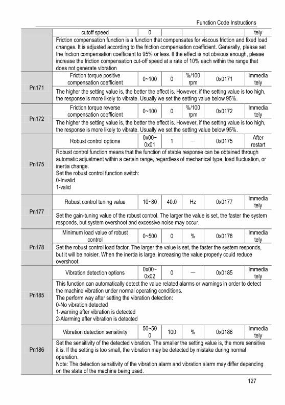
Function Code Instructions
127
cutoff speed 0 tely
Friction compensation function is a function that compensates for viscous friction and fixed load changes. It is adjusted according to the friction compensation coefficient. Generally, please set the friction compensation coefficient to 95% or less. If the effect is not obvious enough, please increase the friction compensation cut-off speed at a rate of 10% each within the range that does not generate vibration
Pn171
Friction torque positive compensation coefficient
0~100 0 %/100
rpm 0x0171
Immediately
The higher the setting value is, the better the effect is. However, if the setting value is too high, the response is more likely to vibrate. Usually we set the setting value below 95%.
Pn172
Friction torque reverse compensation coefficient
0~100 0 %/100
rpm 0x0172
Immediately
The higher the setting value is, the better the effect is. However, if the setting value is too high, the response is more likely to vibrate. Usually we set the setting value below 95%.
Pn175
Robust control options 0x00~0x01
1 - 0x0175 After
restart
Robust control function means that the function of stable response can be obtained through automatic adjustment within a certain range, regardless of mechanical type, load fluctuation, or inertia change. Set the robust control function switch: 0-Invalid 1-valid
Pn177
Robust control tuning value 10~80 40.0 Hz 0x0177 Immedia
tely
Set the gain-tuning value of the robust control. The larger the value is set, the faster the system responds, but system overshoot and excessive noise may occur.
Pn178
Minimum load value of robust control
0~500 0 % 0x0178 Immedia
tely
Set the robust control load factor. The larger the value is set, the faster the system responds, but it will be noisier. When the inertia is large, increasing the value properly could reduce overshoot.
Pn185
Vibration detection options 0x00~0x02
0 - 0x0185 Immedia
tely
This function can automatically detect the value related alarms or warnings in order to detect the machine vibration under normal operating conditions. The perform way after setting the vibration detection: 0-No vibration detected 1-warning after vibration is detected 2-Alarming after vibration is detected
Pn186
Vibration detection sensitivity 50~50
0 100 % 0x0186
Immediately
Set the sensitivity of the detected vibration. The smaller the setting value is, the more sensitive it is. If the setting is too small, the vibration may be detected by mistake during normal operation. Note: The detection sensitivity of the vibration alarm and vibration alarm may differ depending on the state of the machine being used.
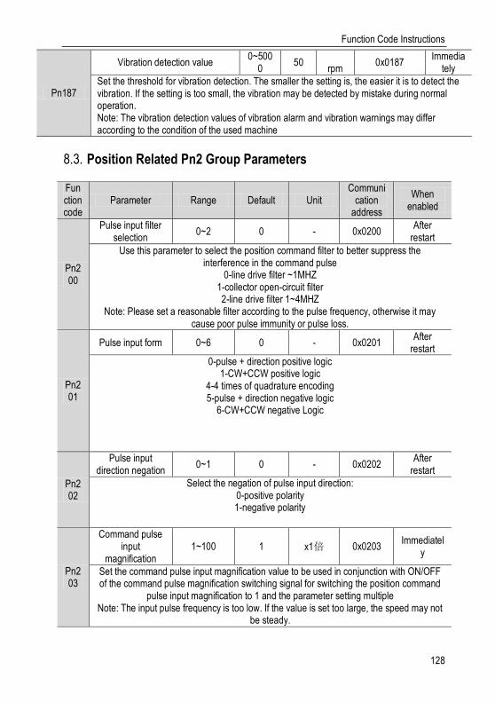
Function Code Instructions
128
Pn187
Vibration detection value 0~500
0 50
rpm 0x0187
Immediately
Set the threshold for vibration detection. The smaller the setting is, the easier it is to detect the vibration. If the setting is too small, the vibration may be detected by mistake during normal operation. Note: The vibration detection values of vibration alarm and vibration warnings may differ according to the condition of the used machine
Position Related Pn2 Group Parameters 8.3.
Function code
Parameter Range Default Unit Communi
cation address
When enabled
Pn200
Pulse input filter selection
0~2 0 - 0x0200 After
restart
Use this parameter to select the position command filter to better suppress the interference in the command pulse
0-line drive filter ~1MHZ 1-collector open-circuit filter 2-line drive filter 1~4MHZ
Note: Please set a reasonable filter according to the pulse frequency, otherwise it may cause poor pulse immunity or pulse loss.
Pn201
Pulse input form 0~6 0 - 0x0201 After
restart
0-pulse + direction positive logic 1-CW+CCW positive logic
4-4 times of quadrature encoding 5-pulse + direction negative logic
6-CW+CCW negative Logic
Pn202
Pulse input direction negation
0~1 0 - 0x0202 After
restart
Select the negation of pulse input direction: 0-positive polarity 1-negative polarity
Pn203
Command pulse input
magnification 1~100 1 x1倍 0x0203
Immediately
Set the command pulse input magnification value to be used in conjunction with ON/OFF of the command pulse magnification switching signal for switching the position command
pulse input magnification to 1 and the parameter setting multiple Note: The input pulse frequency is too low. If the value is set too large, the speed may not
be steady.

Function Code Instructions
129
Pn204
Pn206
Electronic gear ratio numerator
0~1073741824
64 - 0x0206 0x0207
After restart
Electronic gear ratio denominator
1~1073741824
1 - 0x0208 0x0209
After restart
The electronic gear ratio is a function for setting the workpiece movement amount of one pulse unit of the upper device input command. Take the screw drive as an example, it has a screw pitch of 10mm, When the upper system requires that reduction ratio of the motor
shaft and the load side machine is N1/N2 (the motor shaft rotates N2 revolutions when the load shaft rotates N1 revolutions), the set value of the electronic gear ratio is obtained by
the following formula: Electronic Gear Ratio numerator /Electronic Gear Ratio denominator = Encoder Resolution
/ Pulse Number of Upper System 1r * Reduction Ratio N1/N2
Pn211
Position command
low-pass filter time constant
0~655 0 ms 0x0211 After stop
This parameter is used to set the time constant of the first-order low-pass filter corresponding to the position command and it can reduce the mechanical shock in the
case of abrupt changes in the input pulse command frequency by setting this parameter.
Pn212
Average filter time in position
instruction rolling 0~1000 0 ms 0x0212 After stop
This parameter is used to set the time constant of the moving average filter of the corresponding position instruction. It can reduce the mechanical shock in the case of
abrupt changes in the input pulse command frequency by setting this parameter.
Pn230
Low-frequency vibration
suppression options
0x00~0x02 0 - 0x0230 Immediatel
y
This parameter is used with Pn231 as the automatic adjustment mode setting 0 - No vibration suppression
1- Additional vibration suppression function for specific frequency 2-Add vibration suppression to 2 different frequencies
Pn231
Automatic adjustment selection in
low-frequency vibration
suppression
0x00~0x01 1 - 0x0231 Immediatel
y
This parameter is set to choose if the low-frequency vibration suppression is automatically set in the intelligent settings, bandwidth settings and other auxiliary functions:
0 - Vibration suppression function won’t be automatically adjusted via auxiliary functions 1- Vibration suppression function will be automatically adjusted via auxiliary functions
Pn232
Low-frequency vibration
0.1~300 40.0 % 0x0232 Immediatel
y
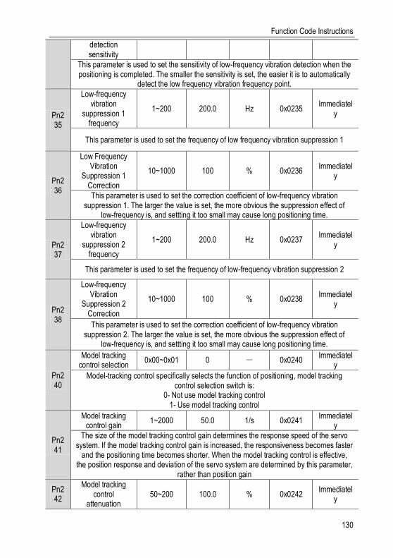
Function Code Instructions
130
detection sensitivity
This parameter is used to set the sensitivity of low-frequency vibration detection when the positioning is completed. The smaller the sensitivity is set, the easier it is to automatically
detect the low frequency vibration frequency point.
Pn235
Low-frequency vibration
suppression 1 frequency
1~200 200.0 Hz 0x0235 Immediatel
y
This parameter is used to set the frequency of low frequency vibration suppression 1
Pn236
Low Frequency Vibration
Suppression 1 Correction
10~1000 100 % 0x0236 Immediatel
y
This parameter is used to set the correction coefficient of low-frequency vibration suppression 1. The larger the value is set, the more obvious the suppression effect of
low-frequency is, and settting it too small may cause long positioning time.
Pn237
Low-frequency vibration
suppression 2 frequency
1~200 200.0 Hz 0x0237 Immediatel
y
This parameter is used to set the frequency of low-frequency vibration suppression 2
Pn238
Low-frequency Vibration
Suppression 2 Correction
10~1000 100 % 0x0238 Immediatel
y
This parameter is used to set the correction coefficient of low-frequency vibration suppression 2. The larger the value is set, the more obvious the suppression effect of
low-frequency is, and settting it too small may cause long positioning time.
Pn240
Model tracking control selection
0x00~0x01 0 - 0x0240 Immediatel
y
Model-tracking control specifically selects the function of positioning, model tracking control selection switch is:
0- Not use model tracking control 1- Use model tracking control
Pn241
Model tracking control gain
1~2000 50.0 1/s 0x0241 Immediatel
y
The size of the model tracking control gain determines the response speed of the servo system. If the model tracking control gain is increased, the responsiveness becomes faster
and the positioning time becomes shorter. When the model tracking control is effective, the position response and deviation of the servo system are determined by this parameter,
rather than position gain
Pn242
Model tracking control
attenuation 50~200 100.0 % 0x0242
Immediately

Function Code Instructions
131
coefficient
The tracking attenuation coefficient of the model decreases, and the position tuning section is easy to cause excessive overshoot. If the setting is too small, the position
oscillates easily. When the setting increases, the position overshoot decreases, but when the position is too large, the position easily rebounds, causing the positioning time to change. Long, it is recommended to keep this value unchanged during normal use.
Pn243
Model tracking control speed
feedforward gain 0~1000 100.0 % 0x0243
Immediately
The feed forward gain of the model tracking speed is reduced, and the responsiveness is slower, but position overshoot doesn’t easily occur. If the feedforward gain is too small, the
position deviation will end in a long time.
Pn244
Model tracking control forward
torque feedforward gain
0~1000 100.0 % 0x0244 Immediatel
y
It’s a forward position command and could be used when adjusting the forward response separately. When it is increased, the torque feed forward rises faster and the positioning
time can be shortened appropriately.
Pn245
Model tracking control reverse
torque feedforward gain
0~1000 100.0 % 0x0245 Immediatel
y
It’s a reverse position command and could be used when adjusting the forward response separately. When it is increased, the torque feed forward rises faster and the positioning
time can be shortened appropriately.
Pn246
Second model tracking control
gain 1~2000 50.0 1/s 0x0246
Immediately
Use second gain when model tracking is valid.
Pn247
Second model tracking control
attenuation coefficient
50~200 100.0 % 0x0247 Immediatel
y
Use second gain when model tracking is valid.
Pn249
Speed feedforward/torqu
e feedforward selection
0x00~0x01 0 - 0x0249 Immediatel
y
0-not use model tracking control and external speed and torque feed forward at the same time
1-use model tracking control and external speed and torque feed forward at the same time When using the model tracking control, the optimal feedforward will be set inside the servo, and it is not recommended to use the "speed feed forward (V-REF) input" and
"torque feed forward (T-REF) input" from the upper unit at the same time. However, it can be used at the same time as needed. In this case, if the input feed forward is incorrect, it
may cause overshoot and system instability.

Function Code Instructions
132
Pn260
Position near signal width
1~1073741824
1073741824
Command unit
0x0260 0x0261
Immediately
In the position control, the host device can receive the positioning proximity signal before confirming the positioning completion signal, so as to prepare for the sequence of actions
after the positioning is completed and shorten the time required for the positioning to complete the operation, The signal will be output as the difference between the command
pulse number of the host device and the servo motor movement (position deviation) is lower than the set value
Pn262
Positioning completion range
0~1073741824
7 Comman
d unit 0x0262 0x0263
Immediately
In the position control, the servo motor positioning completion signal will be output when the difference between the command pulse number from the host device and the servo motor movement amount (position deviation) is lower than the set value that means the
host device confirming positioning has been completed.
Pn264
Maximum position deviation threshold
1~1073741823
5242880 Comman
d unit 0x0264 0x0265
Immediately
When the motor operation does not match the instruction, by setting the appropriate Pn264 (maximum position deviation threshold), an abnormal condition can be detected
and the motor can be stopped.
Pn266
Excessive position deviation warning setting
10~100 100 % 0x0266 Immediatel
y
This parameter is used to set the position deviation excessive warning threshold. When the position deviation is greater than the product of the Pn264 (maximum position
deviation threshold) and this parameter, an excessive position deviation warning will be generated.
Pn267
Position Deviation Alarm Threshold when the Servo is
ON
1~1073741823
5242880 Comman
d unit 0x0267 0x0268
Immediately
This parameter is used to set the threshold for excessive position deviation alarm at the moment of servo ON. When the servo is ON, if the position deviation value exceeds this
setting value, an excessive servo deviation alarm will be generated when the servo is ON.
Pn269
Position Deviation Warning
Threshold when the Servo is ON
10~100 100 % 0x0269 Immediatel
y
This parameter is used to set the warning threshold for excessive position deviation at the servo ON moment. When the servo is turned ON and the position deviation is greater than
the product of “Excessive position deviation warning threshold at servo ON” and the parameter, the warning will be generated when the servo is ON.
Pn270
speed limit value when the Servo is
ON 0~10000 10000 rpm 0x0270
Immediately

Function Code Instructions
133
If the servo is turned ON with the position deviation accumulated, the speed limit is executed by this parameter. When the command pulse is input in this state, the alarm Er.D02 (Excessive position deviation alarm caused by speed limit during servo ON) is
displayed when the set value of Pn264 (maximum position deviation threshold) is exceeded.
Pn272
Position deviation clear mode
0x00~0x03 0 - 0x0272 After
restart
Set the clear mode of the switch position deviation clear signal (/CLR): 0- Cleared when level is ON
1- Cleared when the rising edge OFF->ON 2-Cleared when level is OFF
3- Cleared when the falling edge ON->OFF
Pn273
Position deviation removal method
selection 0x00~0x02 0 - 0x0273
After restart
Set the deviation removal method: 0- Servo OFF, Alarm and /CLR Signal Position Deviation can be cleared
1-/CLR signal position deviation can be cleared 2-Alarm and /CLR signal position deviation can be cleared
Note: 1. For details on the pulse amplitude of the clear signal, refer to the description of “Deviation Clearance”.
2. In the position control, the position deviation remains unchanged when the servo motor stops due to the travel limit.
Pn274
Positioning completion signal
output time 0x00~0x02 0 - 0x0274
After restart
Set the deviation removal method: 0- Servo OFF, Alarm and /CLR Signal Position Deviation can be cleared
1-/CLR signal position deviation can be cleared 2-Alarm and /CLR signal position deviation can be cleared
Note: 1. For details on the pulse amplitude of the clear signal, refer to the description of “Deviation Clearance”.
2. In the position control, the position deviation remains unchanged when the servo motor stops due to the travel limit.
Speed Related Pn3 Group Parameters 8.4.
Function code
Parameter
Range
Default
Unit Communication
address When
enabled
Pn300
Analog speed
command gain
150~3000
600
0.01V/ Rated speed
0x0300 Imme
diately
This parameter is used to set servo motor speed that should be equal to analog voltage value (V-REF) required for the speed command of the rated value.
Caution: Do not apply more than -10~10V and exceeding this range may cause damage to the driver.
Pn301 Analog
speed command
0~1 0 - 0x0301 Imme
diately

Function Code Instructions
134
negation
Set the voltage polarity of the analog speed command: 0-Positive polarity: positive voltage corresponds to positive speed command 1- Negative polarity: positive voltage corresponds to negative speed command
Pn302
Analog speed
instruction filter time
0~655.35
0.40
ms 0x0302 Imme
diately
The function could be set to smooth the speed command when one delay filter is applied to the analog speed command (V-REF) input and it does not usually need to be changed. If the set value is too large, the responsiveness may decrease. Please set this parameter while confirming the response.
Pn303
Analog speed
command dead zone
range
0~3 0 V 0x0303 Imme
diately
In the analog speed control, even if the input command is 0V, the servo motor may rotate at a slight speed. This is because there is a slight deviation in the commands inside the servo unit. This error can be eliminated by setting an appropriate analog speed command deadband range.
Pn304 Pn305 Pn306
Internal speed 1
0~10000
100
rpm 0x0304 Imme
diately
Internal speed 2
0~10000
200
rpm 0x0305 Imme
diately
Internal speed 3
0~10000
300
rpm 0x0306 Imme
diately
When operating in the internal speed mode, the servo unit provides three internal speed commands and through Switch Internal Speed Command Selection A and B we could select as follow:
/SPD-A /SPD-B speed command OFF OFF Zero Speed OFF ON Internal speed 1 ON ON internal speed 2 ON OFF Internal Speed 3
Pn310
Speed command trapezoidal acceleratio
n time
0~10000
0 ms 0x0310 Imme
diately
Acceleration of the set speed from 0r/min to the rated speed (corresponding to the motor model). When the given speed is greater or less than the rated speed, the actual acceleration time is calculated in proportion.
Pn311
Speed command trapezoidal deceleratio
n time
0~10000
0 ms 0x0311 Imme
diately
Acceleration time of the set speed from 0r/min to the rated speed (corresponding to the motor model). When the given speed is greater or less than the rated speed, the actual acceleration time is calculated in proportion.
Pn312
Zero speed clamp mode
0~3 3 - 0x0312 Imme
diately

Function Code Instructions
135
Speed mode, setting the switching speed zero clamp signal (/ZCLAMP) working mode: 0-Invalid 1-speed command is set to 0, not clamped after shutdown 2-speed command is set to 0, clamped after shutdown 3-speed command is lower than "zero speed clamp speed threshold"( Pn313), the first
speed command is set to 0, clamped after shutdown
Pn313
Zero Speed Clamp Speed
Threshold
0~10000
10
rpm 0x0313 Imme
diately
Set the zero control switching threshold when "zero speed clamp mode"( Pn312) is set to 3
Pn317
Rotation
determination
threshold
1~10000
20
rpm
0x0317 Imme
diately
When the motor speed is higher than the set value, the switch rotation detection signal (/TGON) is output.
Pn320
Speed consistent
range
0~100
10
rpm 0x0320
Immediately
When the difference between the motor speed and the command speed is lower than the set value, the switch-speed match signal (/V-CMP) would be output.
Torque Related Pn4 Group Parameters 8.5.
Function code
Parameter
Range
Default
Unit Communication
address When
enabled
Pn400
Torque command selection
0~1 1 - 0x0400 Immed
iately
Select the torque control command source: 0-Internal settings 1- Analog input
Pn401
Torque command
second-order low-pass filter cut-off frequency
100~5000
5000
Hz 0x0401 Immed
iately
This parameter is used to set the cut-off frequency of the second-order torque filter. When this parameter is set to 5000, the filter function is invalid.
Pn402
Torque command
second-order low-pass
filter Q
0.5~1 0.
50 1 0x0402
Immediately
This parameter is used to set the Q value of the second-order torque filter. Increasing the Q value can improve the system response, but noise will be generated when the setting is too large.
Pn403
Torque command direction setting
0~1 0 - 0x0403 Immed
iately

Function Code Instructions
136
Set the switching torque command direction selection (/T-SIGN) signal to activate the switch:
0 - Torque command direction selection (/T-SIGN) signal is invalid 1- Torque command direction selection (/T-SIGN) signal is valid Note: Torque command is invalid when /T-SIGN is valid, torque command is positive when
/T-SIGN signal is ON, and torque command is negative when /T-SIGN signal is OFF.
Pn404
Analog torque
command filter time
0~655.35
0.00
ms 0x0404 Immed
iately
The parameter is used to smooth the torque command when we apply a delay filter to the analog torque command (T-REF) input, usually it does not need to be changed. If the set value is too large, the responsiveness may decrease. So please set it up as we check the response.
Pn405
Analog torque
command gain
10~100
30
0.1V/rated
torque
0x0405 Immed
iately
This parameter is used to set the analog voltage value (T-REF) required for the rated torque of the servo motor.
Caution: Do not apply more than -10~10V, exceeding this range may cause damage to the driver.
Pn406
Analog torque
command negation
0~1 0 - 0x0406 Immed
iately
The analog voltage corresponds to the polarity setting of the torque command: 0-Positive polarity: Positive voltage corresponds to positive torque command 1-Negative polarity: Positive voltage corresponds to negative torque command
Pn407
Analog torque
command dead zone
range
0~3 0 V 0x0407 Immed
iately
In analog torque control, even if the input command is 0V, the servo motor may rotate at a slight speed. This is because a slight deviation occurs in the command inside the servo unit. This error can be eliminated by setting an appropriate analog torque command deadband range.
Pn410
Internal torque
command in torque control
-500~500
0 % 0x0410 Immed
iately
The command source for selecting the torque control is the torque command size setting for internal setting.
Pn411
Speed control mode
setting in torque control
0~1 1 - 0x0411 After
restart
0- select the lower one between the speed corresponding to the analog voltage (V-REF) and the speed set by Pn413
1-select the speed set by Pn413
Pn412
Speed limit
selection
0x00~0x01
0 - 0x0412 After
restart
0-motor maximum speed (determined by internal part of the motor model) + torque mode speed limit (Pn411)
1- Overspeed detection alarm speed (determined by internal part of the motor model) +

Function Code Instructions
137
torque mode speed limit (Pn411)
Pn413
Speed limit in torque control
0~10000
1000
rpm 0x0413 Immed
iately
This parameter is used to set speed limit in torque control with Pn411
Jogging Related Pn0 Group Parameters 8.6.
Function code
Parameter Range
Defaul
t Unit
Communication address
When
enabled
Pn500 JOG speed 0~1000
500
rpm 0x0500 Imm
ediately
Pn502
Program JOG operation mode
0x00~0x05
0 - 0x0502 Imm
ediately
0-(waiting time->forward motion)*number of cycles 1-(waiting time->backward motion)*number of cycles 2-(waiting time->forward motion)*number of cycles->(waiting time->backward
motion)*number of cycles 3-(waiting time->backward motion)*number of cycles->(waiting time->forward
motion)*number of cycles 4-(waiting time->forward motion->waiting time->backward motion)*number of cycles 5-(waiting time->backward motion->waiting time ->forward motion)*number of cycles
Pn503
Program JOG moving distance
1~1073741824
32768
Command unit
0x0503 Imm
ediately
Set the JOG movement distance of the running program as the command unit
Pn505
Program JOG acceleration/decel
erat-ion time
2~10000
100
ms 0x0505 Imm
ediately
Set the time of accelerating from 0r/min to the rated speed (corresponding to the motor model). When the set speed is greater or less than the rated speed, calculate the actual acceleration/deceleration time according to the ratio.
Pn506
Program JOG waiting time
0~10000
100
ms 0x0506 Imm
ediately
Set the waiting time between JOG sections of the running program in conjunction with the program JOG operation mode (Pn502)
Pn507
Program JOG movement times
0~1000
1 回 0x0507 Imm
ediately
Set the movement times of the running program in conjunction with JOG operation mode (Pn502)
Note: it is infinite when set to 0
Pn508 Program JOG
movement speed 1~10000
500
rpm 0x0508 Imm
ediately
Switch Configuration Related Pn6 Group Parameters 8.7.
Function code
Parameter
Range
Default
Unit
Communication address
When enabled
Pn600 Digital
input signal distribution
0~1 1 - 0x0600 After
restart

Function Code Instructions
138
mode
Set the binary input signal distribution method: 0-Internal fixed: used by pins and functions fixed inside the servo unit. See “CN1 terminal”
for details. 1-parameter configuration: It is used according to the function configured on each pin and
is configured and used by function code Pn601~Pn609
Pn601 Pn602 Pn603 Pn604 Pn605 Pn606 Pn607 Pn608 Pn609
CN1-40 input
configuration
0~0x114
0x01
- 0x0601 After
restart
CN1-42 input
configuration
0~0x114
0x02
- 0x0602 After
restart
CN1-43 input
configuration
0~0x114
0x03
- 0x0603 After
restart
CN1-41 input
configuration
0~0x114
0x05
- 0x0604 After
restart
CN1-44 input
configuration
0~0x114
0x04
- 0x0605 After
restart
CN1-45 input
configuration
0~0x114
0x06
- 0x0606 After
restart
CN1-46 input
configuration
0~0x114
0x07
- 0x0607 After
restart
CN1-39 input
configuration
0~0x114
0x00
- 0x0608 After
restart
CN1-38 input
configuration
0~0x114
0x00
- 0x0609 After
restart
0x00: Invalid 0x01: Servo enable 0x101: Servo enable negation 0x02: Run in positive direction 0x102: Run in positive direction is prohibited 0x03: Run in negative direction 0x103: Run in negative direction is prohibited 0x04: Alarm clear 0x104: Counter clear 0x05: Manual P-PI control 0x105: Manual P-PI control negation 0x06: Torque limit switch 0x106: Torque limit switch negation 0x07: Reserved 0x107: Reserved 0x08: Internal speed command direction selection 0x108: Internal speed
command direction selection D negation 0x09: Internal speed command selection A 0x109: Internal speed command selection
A negation 0x0A: Internal speed command selection B 0x10A: Internal speed command selection
B is negation 0x0B: Control mode switch 0x10B: Control mode switch negation 0x0C: Zero speed clamp 0x10C: Zero speed clamp negation 0x0D: Command pulse disable 0x10D: Command pulse disable negation 0x0E: Gain switching 0x10E: Gain switching negation 0x0F: Direction selection of torque command 0x10F: Direction selection of torque
command negation 0x10: Command pulse rate switching 0x110: Command pulse rate switch negation
Pn610 Pn611 Pn612
Switch input
internal
0~0x14
0x00
- 0x0610 After
restart
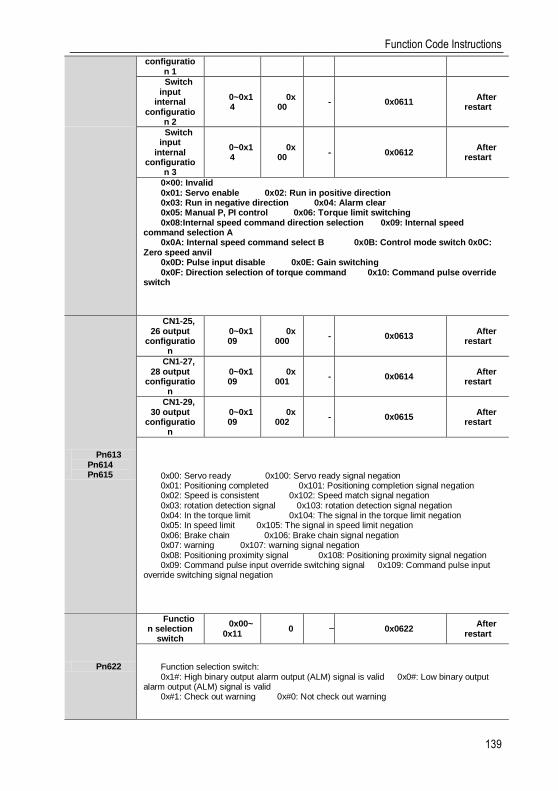
Function Code Instructions
139
configuration 1
Switch input
internal configuratio
n 2
0~0x14
0x00
- 0x0611 After
restart
Switch input
internal configuratio
n 3
0~0x14
0x00
- 0x0612 After
restart
0×00: Invalid 0x01: Servo enable 0x02: Run in positive direction 0x03: Run in negative direction 0x04: Alarm clear 0x05: Manual P, PI control 0x06: Torque limit switching 0x08:Internal speed command direction selection 0x09: Internal speed
command selection A 0x0A: Internal speed command select B 0x0B: Control mode switch 0x0C:
Zero speed anvil 0x0D: Pulse input disable 0x0E: Gain switching 0x0F: Direction selection of torque command 0x10: Command pulse override
switch
Pn613 Pn614 Pn615
CN1-25, 26 output
configuration
0~0x109
0x000
- 0x0613 After
restart
CN1-27, 28 output
configuration
0~0x109
0x001
- 0x0614 After
restart
CN1-29, 30 output
configuration
0~0x109
0x002
- 0x0615 After
restart
0x00: Servo ready 0x100: Servo ready signal negation 0x01: Positioning completed 0x101: Positioning completion signal negation 0x02: Speed is consistent 0x102: Speed match signal negation 0x03: rotation detection signal 0x103: rotation detection signal negation 0x04: In the torque limit 0x104: The signal in the torque limit negation 0x05: In speed limit 0x105: The signal in speed limit negation 0x06: Brake chain 0x106: Brake chain signal negation 0x07: warning 0x107: warning signal negation 0x08: Positioning proximity signal 0x108: Positioning proximity signal negation 0x09: Command pulse input override switching signal 0x109: Command pulse input
override switching signal negation
Pn622
Function selection
switch
0x00~0x11
0 - 0x0622 After
restart
Function selection switch: 0x1#: High binary output alarm output (ALM) signal is valid 0x0#: Low binary output
alarm output (ALM) signal is valid 0x#1: Check out warning 0x#0: Not check out warning
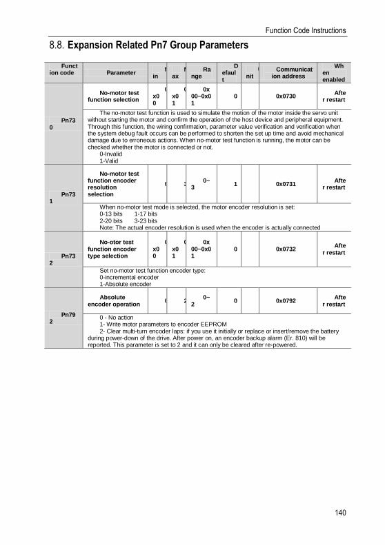
Function Code Instructions
140
Expansion Related Pn7 Group Parameters 8.8.
Function code Parameter
Min
Max
Range
Default
Unit
Communication address
When enabled
Pn730
No-motor test function selection
0x00
0x01
0x00~0x01
0 - 0x0730 Afte
r restart
The no-motor test function is used to simulate the motion of the motor inside the servo unit without starting the motor and confirm the operation of the host device and peripheral equipment. Through this function, the wiring confirmation, parameter value verification and verification when the system debug fault occurs can be performed to shorten the set up time and avoid mechanical damage due to erroneous actions. When no-motor test function is running, the motor can be checked whether the motor is connected or not.
0-Invalid 1-Valid
Pn731
No-motor test function encoder resolution selection
0 3 0~
3 1 - 0x0731
After restart
When no-motor test mode is selected, the motor encoder resolution is set: 0-13 bits 1-17 bits 2-20 bits 3-23 bits Note: The actual encoder resolution is used when the encoder is actually connected
Pn732
No-otor test function encoder type selection
0x00
0x01
0x00~0x01
0 - 0x0732 Afte
r restart
Set no-motor test function encoder type: 0-incremental encoder 1-Absolute encoder
Pn792
Absolute encoder operation
0 2 0~
2 0 - 0x0792
After restart
0 - No action 1- Write motor parameters to encoder EEPROM 2- Clear multi-turn encoder laps: if you use it initially or replace or insert/remove the battery
during power-down of the drive. After power on, an encoder backup alarm (Er. 810) will be reported. This parameter is set to 2 and it can only be cleared after re-powered.

Monitoring Parameters
141
Monitoring Parameters 9.
Monitoring code
Monitoring name range unit
mailing address
Un000 Motor rotation speed 0x80000000~0x7fffffff rpm 0xE000
Display the actual speed of the servo motor
Un001
Speed command 0x80000000~0x7fffffff rpm 0xE001
Display the current speed command of the servo motor Note: When it is not enabled, this value shows the analog speed (corresponding to V-REF)
Un002 Internal torque command 0x80000000~0x7fffffff % 0xE002
Display current actual torque command with servo motor rated torque as 100%
Un003
Rotor pulse position relative to the Z axis
0x80000000~0x7fffffff pulse 0xE003
Shows the mechanical absolute position of the motor within one revolution of the encoder
Un004 Electrical angle 0x80000000~0x7fffffff ° 0xE004
Displays the electrical angle of the current position of the servo motor rotor
Un005
Speed of input pulse command
0x80000000~0x7fffffff rpm 0xE005
Display input position pulse command speed
Un006
Counter of input command pulse
0x80000000~0x7fffffff Command
Unit 0xE006
Displays the number of command pulses received by the servo motor
Un007 Counter of feedback pulse 0x80000000~0x7fffffff
Command Unit 0xE007
Displays cumulative pulses fed back from the servo motor encoder
Un008
Counter of feedback pulse 1
0x80000000~0x7fffffff Encoder pulse
unit 0xE008
Displays cumulative pulses fed back from the servo motor encoder
Un009 Position deviation
0x80000000~0x7fffffff Command
Unit 0xE009
Display the difference between the command pulse number of the upper device and the servo motor movement amount
Un00A Cumulative load rate 0x80000000~0x7fffffff % 0xE00A
Un00B Regeneration load rate 0x80000000~0x7fffffff % 0xE00B
Un00C Electricity consumption of
DB resistance 0x80000000~0x7fffffff %
0xE00C
Un00D Effective gain monitoring 1~2 - 0xE00D
Un00E Total running time 0~0xFFFFFFFF 100ms 0xE00E
Un00F Overload rate 0~0xFFFFFFFF % 0xE00F
Un035 DSP software version 0~0xFFFF - 0xE035

Monitoring Parameters
142
Un036 FPGA software version 0~0xFFFF - 0xE036
Un089 Heat sink temperature 0~0xFFFF ℃ 0xE090
Un100
IO port input signal monitoring
0~0xFFFF - 0xE100
See "3.3.3 Confirming the input status" for details
Un101
IO port output signal monitoring
0~0xFFFF - 0xE101
See "3.3.3 Confirming the output status" for details
Un102
T-REF monitoring 0~0xFFFF % 0xE102
Corresponds to the T-REF input voltage, according to the analog torque command gain
Un103 V-REF monitoring 0~0xFFFF rpm 0xE103
Corresponds to the T-REF input voltage, according to the analog torque command gain
Un104 Pulse command input
frequency 0~0xFFFFFFFF Hz 0xE104
Un108 External input command
pulse counter 0~0xFFFFFFFF
Command Unit
0xE108
Un110 Integrated monitoring of
internal signal status 0~0xFFFFFFFF - 0xE110
Un120 Integrated monitoring of
internal input signal status 0~0xFFFFFFFF - 0xE120
Un130 Integrated monitoring of
internal output signal 0~0xFFFFFFFF - 0xE130
Un140 Main circuit bus voltage 0~0xFFFF V 0xE140
Un141 Effective current feedback 0~0xFFFF 0.01A 0xE141
Three-phase synthetic feedback current effective value
Un300 Current alarm code 0~0xFFFF - 0xE300
Un301 Last alarm code 0~0xFFFF - 0xE301
Un302 Timestamp while alarm
occurs 0~0xFFFFFFFF 100ms 0xE302
Un303 Motor speed while alarm
occurs 0~0xFFFF rpm 0xE303
Un304 Speed command while
alarm occurs 0~0xFFFF rpm 0xE304
Un305 Internal torque command
while alarm occurs 0~0xFFFF % 0xE305
Un306 Input command pulse
speed while alarm occurs 0~0xFFFF rpm 0xE306
Un307 Deviation counters (position
deviation)while alarm occurs
0~0xFFFFFFFF pulse 0xE307
Un308 DC bus voltage while alarm
occurs 0~0xFFFF V 0xE308
Un309 Effective current feedback
while alarm occurs 0~0xFFFF % 0xE309

Monitoring Parameters
143
Un30A Cumulative load rate while
alarm occurs 0~0xFFFF % 0xE30A
Un30B Regenerative load rate
while alarm occurs 0~0xFFFF % 0xE30B
Un30C Electricity consumption of DB resistance while alarm
occurs 0~0xFFFF % 0xE30C
Un30D Maximum cumulative load
rate while alarm occurs 0~0xFFFF % 0xE30D
Un30E Rotation inertia ratio while
alarm occurs 0~0xFFFF % 0xE30E
Un30F Abnormal times of serial encoder communication
while alarm occurs 0~0xFFFF - 0xE30F
Un310 Internal signal monitoring
while alarm occurs 0~0xFFFFFFFF - 0xE310
Un313 Internal input signal
monitoring while alarm occurs
0~0xFFFFFFFF - 0xE313
Un317 Internal output signal
monitoring while alarm occurs
0~0xFFFFFFFF - 0xE317
Un320 Fault code history 1 0~0xFFFF - 0xE320
Un321 Fault code history 2 0~0xFFFF - 0xE321
Un322 Fault code history 3 0~0xFFFF - 0xE322
Un323 Fault code history 4 0~0xFFFF - 0xE323
Un324 Fault code history 5 0~0xFFFF - 0xE324
Un325 Fault code history 6 0~0xFFFF - 0xE325
Un326 Fault code history 7 0~0xFFFF - 0xE326
Un327 Fault code history 8 0~0xFFFF - 0xE327
Un328 Fault code history 9 0~0xFFFF - 0xE328
Un329 Fault code history 10 0~0xFFFF - 0xE329
Un330 Fault time history 1 0~0xFFFFFFFF 100ms 0xE330
Un331 Fault time history 2 0~0xFFFFFFFF 100ms 0xE331
Un332 Fault time history 3 0~0xFFFFFFFF 100ms 0xE332
Un333 Fault time history 4 0~0xFFFFFFFF 100ms 0xE333
Un334 Fault time history 5 0~0xFFFFFFFF 100ms 0xE334
Un335 Fault time history 6 0~0xFFFFFFFF 100ms 0xE335
Un336 Fault time history 7 0~0xFFFFFFFF 100ms 0xE336
Un337 Fault time history 8 0~0xFFFFFFFF 100ms 0xE337
Un338 Fault time history 9 0~0xFFFFFFFF 100ms 0xE338
Un339 Fault time history 10 0~0xFFFFFFFF 100ms 0xE339
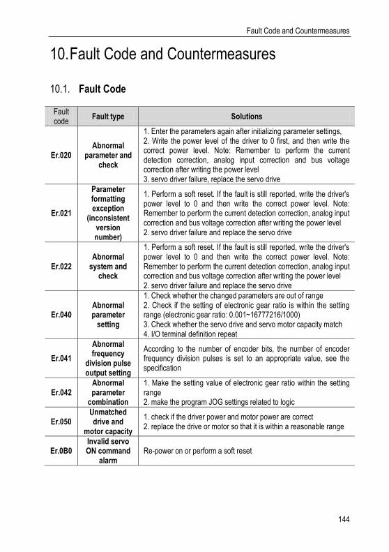
Fault Code and Countermeasures
144
Fault Code and Countermeasures 10.
Fault Code 10.1.
Fault code
Fault type Solutions
Er.020 Abnormal
parameter and check
1. Enter the parameters again after initializing parameter settings, 2. Write the power level of the driver to 0 first, and then write the correct power level. Note: Remember to perform the current detection correction, analog input correction and bus voltage correction after writing the power level 3. servo driver failure, replace the servo drive
Er.021
Parameter formatting exception
(inconsistent version number)
1. Perform a soft reset. If the fault is still reported, write the driver's power level to 0 and then write the correct power level. Note: Remember to perform the current detection correction, analog input correction and bus voltage correction after writing the power level 2. servo driver failure and replace the servo drive
Er.022 Abnormal
system and check
1. Perform a soft reset. If the fault is still reported, write the driver's power level to 0 and then write the correct power level. Note: Remember to perform the current detection correction, analog input correction and bus voltage correction after writing the power level 2. servo driver failure and replace the servo drive
Er.040 Abnormal parameter
setting
1. Check whether the changed parameters are out of range 2. Check if the setting of electronic gear ratio is within the setting range (electronic gear ratio: 0.001~16777216/1000) 3. Check whether the servo drive and servo motor capacity match 4. I/O terminal definition repeat
Er.041
Abnormal frequency
division pulse output setting
According to the number of encoder bits, the number of encoder frequency division pulses is set to an appropriate value, see the specification
Er.042 Abnormal parameter
combination
1. Make the setting value of electronic gear ratio within the setting range 2. make the program JOG settings related to logic
Er.050 Unmatched drive and
motor capacity
1. check if the driver power and motor power are correct 2. replace the drive or motor so that it is within a reasonable range
Er.0B0 Invalid servo ON command
alarm Re-power on or perform a soft reset
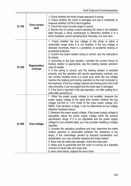
Fault Code and Countermeasures
145
Er.100 Over-current
fault
1. Check whether the motor phase sequence is wrong 2. Check whether the motor is damaged and use a multimeter to measure whether U/V/W is short together. 3. Check the motor encoder angle is correct 4. Monitor the UV phase current sampling AD value in the disabled state through a virtual oscilloscope to determine whether it is a driver hardware current sampling fault. Normally, it is near zero.
Er.320 Regeneration
overload
1. Check whether the bus voltage of the driver is within a reasonable range when it is not enabled. If the bus voltage is detected incorrectly, there is a possibility of accidental braking or accidental protection. 2. Confirm the brake resistor wiring is correct; see the instructions for details. 3. According to the load situation, consider the current choice of braking resistor is appropriate; see the braking resistor selection rules for details. 4. If the wiring is correct, and the braking resistor is selected properly, and the operation still reports regenerative overload, you can monitor whether there is a small drop when the bus voltage reaches the braking point during operation by the host computer or the keyboard. If the bus voltage reaches the braking point and it still rises smoothly, it can be judged that the brake pipe is damaged. 5. If the fault is reported in the last operation, run after waiting for a while after powering on.
Er.400 Over-voltage
1. When the power supply voltage is not enabled, measure the power supply voltage at the same time monitor whether the bus voltage (Un140) is 1.414 times of the input power voltage (AC RMS). If the deviation is large, it can be determined as bus voltage detection hardware failure. 2. Measure the power supply voltage. If the power supply voltage is adjustable, adjust the power supply voltage within the product specification range. If it is not adjustable and the power supply voltage is in an unstable state, you may consider installing a voltage regulator. 3, consider the operating conditions and load, determine the brake resistor selection is reasonable (whether the resistance is too large), if the overvoltage caused by frequent acceleration and deceleration, you may consider replacing the brake resistor 4. there may be brake pipe damage, check the brake pipe 5. Make sure to guarantee that the motor is running at a tolerable moment of inertia ratio and mass ratio 6, servo drive failure, replace the servo drive
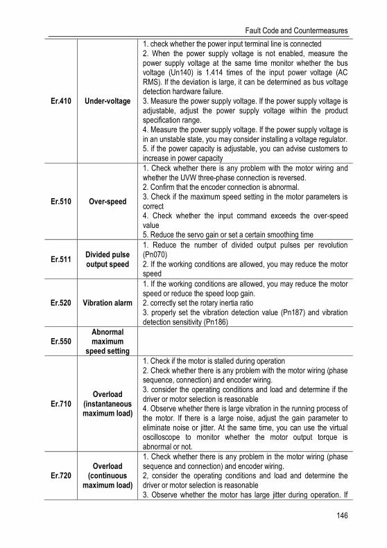
Fault Code and Countermeasures
146
Er.410 Under-voltage
1. check whether the power input terminal line is connected 2. When the power supply voltage is not enabled, measure the power supply voltage at the same time monitor whether the bus voltage (Un140) is 1.414 times of the input power voltage (AC RMS). If the deviation is large, it can be determined as bus voltage detection hardware failure. 3. Measure the power supply voltage. If the power supply voltage is adjustable, adjust the power supply voltage within the product specification range. 4. Measure the power supply voltage. If the power supply voltage is in an unstable state, you may consider installing a voltage regulator. 5. if the power capacity is adjustable, you can advise customers to increase in power capacity
Er.510 Over-speed
1. Check whether there is any problem with the motor wiring and whether the UVW three-phase connection is reversed. 2. Confirm that the encoder connection is abnormal. 3. Check if the maximum speed setting in the motor parameters is correct 4. Check whether the input command exceeds the over-speed value 5. Reduce the servo gain or set a certain smoothing time
Er.511 Divided pulse output speed
1. Reduce the number of divided output pulses per revolution (Pn070) 2. If the working conditions are allowed, you may reduce the motor speed
Er.520 Vibration alarm
1. If the working conditions are allowed, you may reduce the motor speed or reduce the speed loop gain. 2. correctly set the rotary inertia ratio 3. properly set the vibration detection value (Pn187) and vibration detection sensitivity (Pn186)
Er.550 Abnormal maximum
speed setting
Er.710 Overload
(instantaneous maximum load)
1. Check if the motor is stalled during operation 2. Check whether there is any problem with the motor wiring (phase sequence, connection) and encoder wiring. 3. consider the operating conditions and load and determine if the driver or motor selection is reasonable 4. Observe whether there is large vibration in the running process of the motor. If there is a large noise, adjust the gain parameter to eliminate noise or jitter. At the same time, you can use the virtual oscilloscope to monitor whether the motor output torque is abnormal or not.
Er.720 Overload
(continuous maximum load)
1. Check whether there is any problem in the motor wiring (phase sequence and connection) and encoder wiring. 2, consider the operating conditions and load and determine the driver or motor selection is reasonable 3. Observe whether the motor has large jitter during operation. If

Fault Code and Countermeasures
147
there is a huge noise, adjust the gain parameter to eliminate noise or jitter. Also, use a virtual oscilloscope to monitor whether the motor output torque is abnormal.
Er.730 DB overload 1
1. The load is too heavy when the machine stops that cause the overload of DB resistor and you could try to reduce the operating speed or reduce the load. 2. check whether the motor is driven by external force 3. according to customer needs, re-evaluate whether it needs to pass the DB mode requirements during the shutdown, if you do not need, you can choose other ways to stop 4. If the fault is reported in the last operation, run after waiting for a while after powering on.
Er.7A0 Heat sink over-heat
1. Check whether the air duct is blocked and the fan is damaged with a fan drive. 2. Check the installation conditions of the driver, whether the heat dissipation condition is good or not and increase the heat dissipation condition of the driver as much as possible. 3. Check the drive load conditions, if the load is too heavy, you can suggest that customers replace a high-power segment of the drive. 4. If possible, reduce the driver carrier frequency
Er.810 Abnormal encoder backup
1. Check the multi-turn encoder battery power condition 2. Perform multi-turn encoder clear operation
Er.830 Battery
under-voltage Replace multi-turn encoder battery
Er.BF4 Hardware
over-current
Unplug the power cable and turn on the servo unit again. If an alarm still occurs, the servo unit may be malfunctioning, and then you could replace the servopack. If not, confirm whether it is power line or motor failure
Er.C10 Out of control
alarm
1. Check if the motor wiring is normal 2. Check if the motor and encoder are normal 3. Re-connect the servo drive power, if an alarm still occurs, it may be a servo drive failure
Er.C90
Encoder communication
failure: line-broken
1. Use multimeter to test every signal line of the encoder line and see if signal lines break. 2. Check the encoder line model and confirm the model is correct. 3. Check the length of the encoder line and the encoder line can not be too long. 4. It may be caused by interference, try to ground the driver or wire the encoder around the magnetic ring 5. check the motor group parameters and confirm the motor is correct 6. If you already exclude various reasons and the servo driver may malfunction, then you could consider replacing the servo unit.
Er.C91
Abnormal encoder
communication position data acceleration
Er.CA0 Abnormal encoder
parameters

Fault Code and Countermeasures
148
Er.D00 Excessive position deviation
1. Set the appropriate position deviation excessive alarm value 2. Check whether the encoder cable and motor cable are connected properly. You can use the hand to rotate the motor and monitor whether the Un003 (rotor relative Z pulse position) varies between 0 and 16777216 (24-bit encoder). 3. Calculate the pulse frequency input and acceleration planning and check if the electronic gear ratio setting is reasonable 4. Determine whether the relevant parameters are reasonable. For example: you could check the torque limit, speed limit, inertia ratio, position gain, speed gain is too small or the position filter is too large, etc. 5. Calculate if the motor selection is too small or the acceleration and deceleration are too slow that cause huge position deviation.
Er.D01
Excessive position deviation
during servo ON
Set correct value of Pn267 (overrunning position deviation when servo is ON)
Er.D02
Excessive position
deviation alarm caused by speed limit
during servo ON
Set correct Maximum position deviation threshold (Pn264) or set correct speed limit value (Pn270) during servo ON.

Fault Code and Countermeasures
149
Warning Code 10.2.
Warning code
Type Solutions
AL.900 Excessive
Position deviation warning
1. Correctly set relevant parameters such as gear ratio, gain, position filtering, torque limit, etc.
2. confirm the encoder line motor wiring is correct
3. If you already exclude various reasons, the servo driver may malfunction and you could consider replacing the servo unit.
AL.901
Excessive position deviation
warning during servo ON
Set correct excessive position deviation value during servo ON
AL.910 Overload warning
1. Check if there is any problem of the motor wiring and encoder wiring.
2. Incorrect motor or driver selection
AL.911 Vibration warning 1. Reduce the motor speed or reduce the speed loop gain.
2. Set the moment of inertia ratio correctly
AL.920 Regeneration
overload warning
1. Set the power supply voltage within the specification range.
2. Set resistance value and capacity correctly
3. Replace the servo drive because of servo driver failure
AL.921 DB overload
warning
1. Reduce the servo motor command speed.
2. Reduce the rotary inertia ratio.
3. Replace the servo drive because of servo driver failure
AL.930 Battery
under-voltage warning
Replace the battery
AL.941
Parameter change warning
needed to re-power off
Power down the drive before restart it
AL.971 Under-voltage
warning
1. Adjust the AC/DC power supply voltage to the product specifications.
2. increase the power capacity.
Communication
150
Communication 11.
Communication introduction 11.1.
Servo driver can support RS485, CANopen bus type, EtherCAT bus type, MECHATROLINK-II bus type. Here we mainly introduce the related content of general model RS485 communication. Other communication needs to refer to the special communication manual. 485 communications can realize the following functions.
a) Read and write servo driver function code related parameters
b) Monitor the working status of the servo drive
c) Constitute a multi-axis control system
d) Operate the servo assist function
RS485 communication protocol description 11.2.
Provide RS485 communication interface, the wiring is detailed in CN6, and the master-slave communication is carried out by the international standard Modbus communication protocol. Users can achieve centralized control through PC/PLC, control PC, etc. to suit specific application requirements.
The Modbus serial communication protocol defines the frame content and usage format for asynchronous transmission in serial communication. These include: host polling and broadcast frame, slave response frame format; host organization frame content includes: slave address (or broadcast address), execution commands, data and error check. The response of the slave is also the same structure, including: action confirmation, return data and error check. If the slave encounters an error while receiving a frame, or fails to complete the action requested by the host, it will organize a fault frame as a response to the host.
The communication protocol is an asynchronous serial master-slave Modbus communication protocol. Only one device (host) in the network can establish a protocol (called "query/command"). Other devices (slave) can only respond to the host's "query/command" by providing data, or according to the host's "query/command". The host here refers to a personal computer (PC), an industrial control device or a programmable logic controller (PLC), etc. The slave refers to a servo drive or other control device having the same communication protocol. The host can communicate with a slave separately and broadcast information to all slaves. For a host "query/command" that is accessed separately, the slave must return a message (called a response). For the broadcast message sent by the host, the slave does not need to feed back the response message to the host.
Communication frame structure 11.3.
Modbus only supports RTU transmission mode. The user can configure the serial communication parameters (baud rate, check mode, etc.).

Communication
151
Each 8Bit byte in the message frame contains two 4Bit hexadecimal characters.
Start bit Device address
command data CRC check Terminator
T1-T2-T3-T4 8Bit 8Bit N 8Bit 16Bit T1-T2-T3-T4
In this mode, the message transmission starts at least at a pause interval of 3.5 characters. During transmission, the network device continuously detects the network bus, including the pause interval. When the first field (address field) is received, the corresponding device decodes the next transmitted character, and if there is a pause of at least 3.5 characters, it indicates the end of the message.
In RTU mode, the entire message frame must be transmitted as a continuous stream. If there is a pause time of more than 1.5 characters before the frame is completed, the receiving device will refresh the incomplete message and assume that the next byte is the address of a new message. area. Similarly, if a new message begins with the previous message in less than 3.5 character times, the receiving device will consider it a continuation of the previous message. If the above two situations occur during the transmission, the CRC check will inevitably generate an error message and feed back to the sender device.
Command code and communication data description 11.4.
In the communication command, the data address read and written is the hexadecimal number of the parameter name, for example, the address of the inertia ratio Pn100 is 0x0100.
(1) Command code: 03H
Function: Read N words (Word can read up to 16 words in succession).
For example, if the servo drive with the slave address 01H reads the address e003 and reads two consecutive words, the structure of the frame is described as follows.
Host command information:
START T1-T2-T3-T4(3.5 bytes of transmission time)
ADDR 01H
CMD 03H
Read start address high e0H
Read start address low 03H
high number of data (in word) 00H
low number of data is (in word) 02H
CRC CHK low bit 03H
CRC CHK high bit CBH
END T1-T2-T3-T4(3.5 bytes of transmission time)
The slave responds to the message:
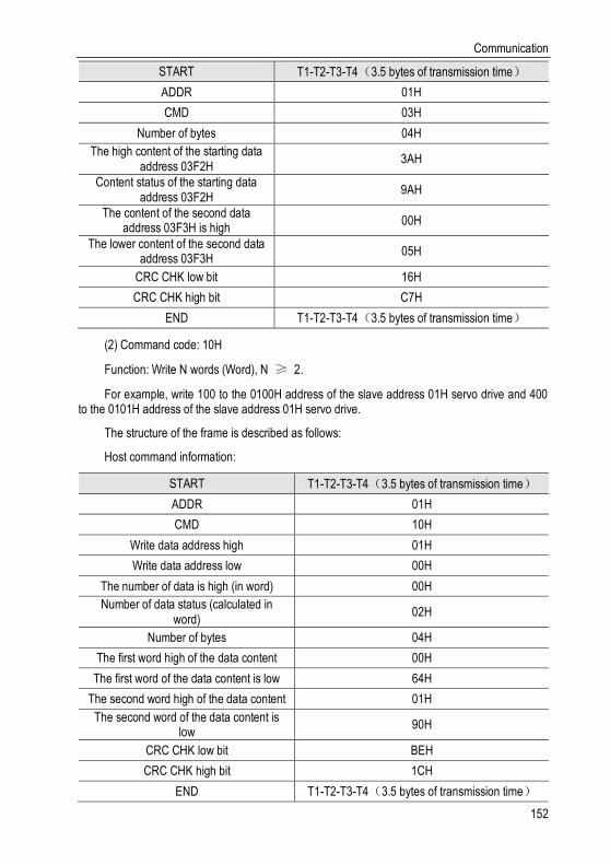
Communication
152
START T1-T2-T3-T4(3.5 bytes of transmission time)
ADDR 01H
CMD 03H
Number of bytes 04H
The high content of the starting data address 03F2H
3AH
Content status of the starting data address 03F2H
9AH
The content of the second data address 03F3H is high
00H
The lower content of the second data address 03F3H
05H
CRC CHK low bit 16H
CRC CHK high bit C7H
END T1-T2-T3-T4(3.5 bytes of transmission time)
(2) Command code: 10H
Function: Write N words (Word), N ≥ 2.
For example, write 100 to the 0100H address of the slave address 01H servo drive and 400 to the 0101H address of the slave address 01H servo drive.
The structure of the frame is described as follows:
Host command information:
START T1-T2-T3-T4(3.5 bytes of transmission time)
ADDR 01H
CMD 10H
Write data address high 01H
Write data address low 00H
The number of data is high (in word) 00H
Number of data status (calculated in word)
02H
Number of bytes 04H
The first word high of the data content 00H
The first word of the data content is low 64H
The second word high of the data content 01H
The second word of the data content is low
90H
CRC CHK low bit BEH
CRC CHK high bit 1CH
END T1-T2-T3-T4(3.5 bytes of transmission time)
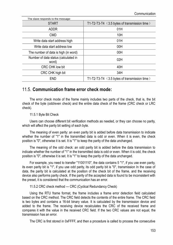
Communication
153
The slave responds to the message:
START T1-T2-T3-T4(3.5 bytes of transmission time)
ADDR 01H
CMD 10H
Write data start address high 01H
Write data start address low 00H
The number of data is high (in word) 00H
Number of data status (calculated in word)
02H
CRC CHK low bit 40H
CRC CHK high bit 34H
END T1-T2-T3-T4(3.5 bytes of transmission time)
Communication frame error check mode: 11.5.
The error check mode of the frame mainly includes two parts of the check, that is, the bit check of the byte (odd/even check) and the entire data check of the frame (CRC check or LRC check).
11.5.1 Byte Bit Check
Users can choose different bit verification methods as needed, or they can choose no parity, which will affect the parity bit setting of each byte.
The meaning of even parity: an even parity bit is added before data transmission to indicate whether the number of "1" in the transmitted data is odd or even. When it is even, the check position is "0", otherwise it is set. It is "1" to keep the parity of the data unchanged.
The meaning of the odd check: an odd parity bit is added before the data transmission to indicate whether the number of "1" in the transmitted data is odd or even. When it is odd, the check position is "0", otherwise it is set. It is "1" to keep the parity of the data unchanged.
For example, you need to transfer "11001110", the data contains 5 "1", if you use even parity, its even parity bit is "1", if you use odd parity, its odd parity bit is "0", transmission In the case of data, the parity bit is calculated at the position of the check bit of the frame, and the receiving device also performs parity check. If the parity of the accepted data is found to be inconsistent with the preset, it is considered that the communication has an error.
11.5.2 CRC check method --- CRC (Cyclical Redundancy Check)
Using the RTU frame format, the frame includes a frame error detection field calculated based on the CRC method. The CRC field detects the contents of the entire frame. The CRC field is two bytes and contains a 16-bit binary value. It is calculated by the transmission device and added to the frame. The receiving device recalculates the CRC of the received frame and compares it with the value in the received CRC field. If the two CRC values are not equal, the transmission has an error.
The CRC is first stored in 0xFFFF, and then a procedure is called to process the consecutive
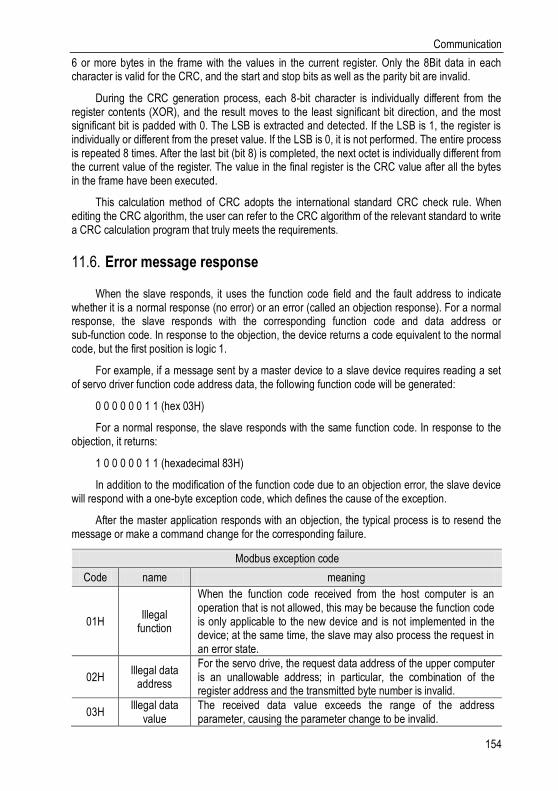
Communication
154
6 or more bytes in the frame with the values in the current register. Only the 8Bit data in each character is valid for the CRC, and the start and stop bits as well as the parity bit are invalid.
During the CRC generation process, each 8-bit character is individually different from the register contents (XOR), and the result moves to the least significant bit direction, and the most significant bit is padded with 0. The LSB is extracted and detected. If the LSB is 1, the register is individually or different from the preset value. If the LSB is 0, it is not performed. The entire process is repeated 8 times. After the last bit (bit 8) is completed, the next octet is individually different from the current value of the register. The value in the final register is the CRC value after all the bytes in the frame have been executed.
This calculation method of CRC adopts the international standard CRC check rule. When editing the CRC algorithm, the user can refer to the CRC algorithm of the relevant standard to write a CRC calculation program that truly meets the requirements.
Error message response 11.6.
When the slave responds, it uses the function code field and the fault address to indicate whether it is a normal response (no error) or an error (called an objection response). For a normal response, the slave responds with the corresponding function code and data address or sub-function code. In response to the objection, the device returns a code equivalent to the normal code, but the first position is logic 1.
For example, if a message sent by a master device to a slave device requires reading a set of servo driver function code address data, the following function code will be generated:
0 0 0 0 0 0 1 1 (hex 03H)
For a normal response, the slave responds with the same function code. In response to the objection, it returns:
1 0 0 0 0 0 1 1 (hexadecimal 83H)
In addition to the modification of the function code due to an objection error, the slave device will respond with a one-byte exception code, which defines the cause of the exception.
After the master application responds with an objection, the typical process is to resend the message or make a command change for the corresponding failure.
Modbus exception code
Code name meaning
01H Illegal
function
When the function code received from the host computer is an operation that is not allowed, this may be because the function code is only applicable to the new device and is not implemented in the device; at the same time, the slave may also process the request in an error state.
02H Illegal data
address
For the servo drive, the request data address of the upper computer is an unallowable address; in particular, the combination of the register address and the transmitted byte number is invalid.
03H Illegal data
value The received data value exceeds the range of the address parameter, causing the parameter change to be invalid.

Host Debugging Instruction
155
Modbus exception code
Code name meaning
11H Parity error
When the RTU format CRC check bit or the ASCII format LRC check bit is different from the check calculation number of the lower computer in the frame information sent by the host computer, the check error information is reported.
Host Debugging Instruction 12.
System Requirements 12.1.
System Configuration 12.1.1.
1. When the user uses the software for the first time, please confirm whether the NET3.5 and NET4.0 frameworks are installed. This is a prerequisite; otherwise the software cannot be opened. But for Win7 and above operating systems, there is no need to install NET 3.5 and NET 4.0 frameworks.
2. The host computer system currently supports USB communication debugging.
3. The system only supports servo SD700 series servo product debugging;
4. Verify that the "Use FIPS-compliant algorithms for encryption" option is set to disabled (Control Panel - Administrative Tools - Local Security Policy - Security Options - Use FIPS-compliant algorithms for encryption - disabled)
Connection Configuration 12.1.2.
The servo driver is connected to the computer through the communication connector, and the interface type is USB. Basic configuration:
1. Anti-jamming Android micro phone data cable.
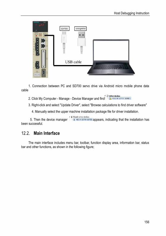
Host Debugging Instruction
156
1. Connection between PC and SD700 servo drive via Android micro mobile phone data cable
2. Click My Computer - Manage - Device Manager and find
3. Right-click and select "Update Driver", select "Browse calculations to find driver software"
4. Manually select the upper machine installation package file for driver installation.
5. Then the device manager appears, indicating that the installation has been successful.
Main Interface 12.2.
The main interface includes menu bar, toolbar, function display area, information bar, status bar and other functions, as shown in the following figure;

Host Debugging Instruction
157
Menu bar
The menu bar includes functions such as files, settings, tools, advanced applications, windows, and help;
[File]: Open and exit the system;
[Settings]: user rights, service personnel rights, developer rights;
[Tools]: parameter settings, real-time monitoring, digital oscilloscope, fault information, screenshots and other functions;
[Advanced applications]: inertia identification, JOG, program JOG, homing, mechanical characteristics, FFT analysis, single parameter adjustment, intelligent adjustment, offset adjustment;
[Window]: Cascading display, horizontal display, vertical display, all off;
[Help]: about;
[Toolbar]
The toolbar includes communication disconnection, communication connection, JOG, program JOG, soft reset, factory reset, parameter setting, monitoring parameters, digital oscilloscope, fault maintenance, screenshot, mechanical characteristics, FFT analysis, intelligent adjustment, offset adjustment, single parameter adjustment, exit and other functions;
Function display area
The function display area is used as a form container to provide sub-window display of reading and writing parameters, monitoring parameters, digital oscilloscope, fault maintenance, and function debugging;
Information columns
[Some parameters] show supplementary explanation

Host Debugging Instruction
158
Status bar
The status bar includes the current communication status and servo work status.
Features 12.3.
File
Documents include open, exit, etc.;
Turn on
Open function: open the existing file;
Step:
Click the menu bar [File] -> [Open] -> [Select the current system directory folder Test32] -> [Select VCDGSmsyc.vcb file];
Exit
Exit function: Close the current system
Step:
Click [Exit] in the file column, exit the system, or click [Exit System] on the motor toolbar to exit the system.
Read and write parameters
Read and write parameters include functions such as reading and writing of function codes, import, and export;
Step:
1. Start reading and writing parameters interface:
Click on the menu bar "Tools" -> "Parameter Settings"
2. The pop-up read/write parameters (parameter setting) interface is displayed in the display area, as shown in the following figure:

Host Debugging Instruction
159
1- Toolbar
The toolbar includes reading the current page function code, reading all page function codes, writing function codes to EERPOM, exporting the current page function code, exporting all function codes, importing function codes in batches, comparing the differences of two file parameters and finding out modified parameters, as shown below:
2-Multi page
Each page is displayed in different functional groups. At the same time, common parameters and different parameter pages are added to facilitate viewing of function codes.
3-function code
The function code is a specific function and provides relevant information such as the current state, name, current value, unit, default value, minimum value, maximum value, and attribute, etc. When a row is clicked, the corresponding function code comment is provided as below;
: Waiting : Communication is normal
4─ Information column
Display parameter modification after the effective mode and function code supplementary explanation;
Function code reading
Function code reading can be read individually or in batches.
Step:
1. Current group read: switch to a group of parameters, left-click on [read] -> select [current group], read the current group parameters
2. Read all: Left-click on [Read] -> Select [All] to read all parameters and the pop-up dialog box will display the progress of the read function code in the form of a progress bar; as shown in the following figure:
Function code write/import
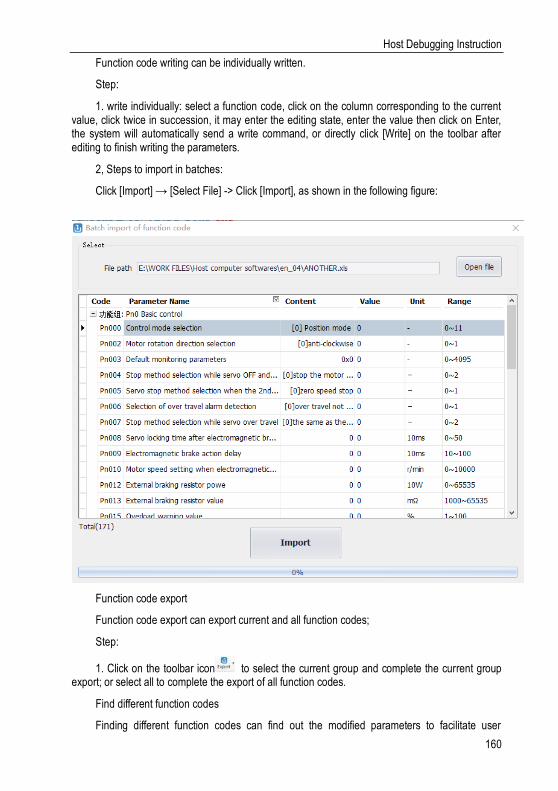
Host Debugging Instruction
160
Function code writing can be individually written.
Step:
1. write individually: select a function code, click on the column corresponding to the current value, click twice in succession, it may enter the editing state, enter the value then click on Enter, the system will automatically send a write command, or directly click [Write] on the toolbar after editing to finish writing the parameters.
2, Steps to import in batches:
Click [Import] → [Select File] -> Click [Import], as shown in the following figure:
Function code export
Function code export can export current and all function codes;
Step:
1. Click on the toolbar icon to select the current group and complete the current group export; or select all to complete the export of all function codes.
Find different function codes
Finding different function codes can find out the modified parameters to facilitate user
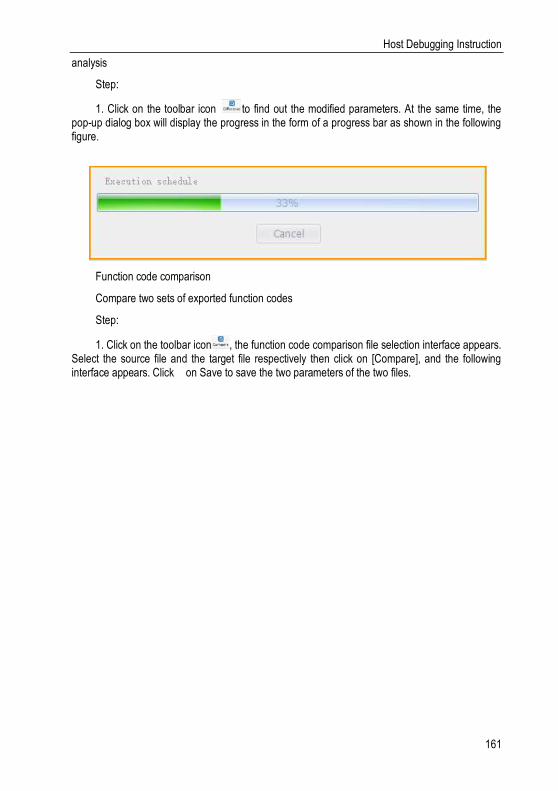
Host Debugging Instruction
161
analysis
Step:
1. Click on the toolbar icon to find out the modified parameters. At the same time, the pop-up dialog box will display the progress in the form of a progress bar as shown in the following figure.
Function code comparison
Compare two sets of exported function codes
Step:
1. Click on the toolbar icon , the function code comparison file selection interface appears. Select the source file and the target file respectively then click on [Compare], and the following interface appears. Click on Save to save the two parameters of the two files.
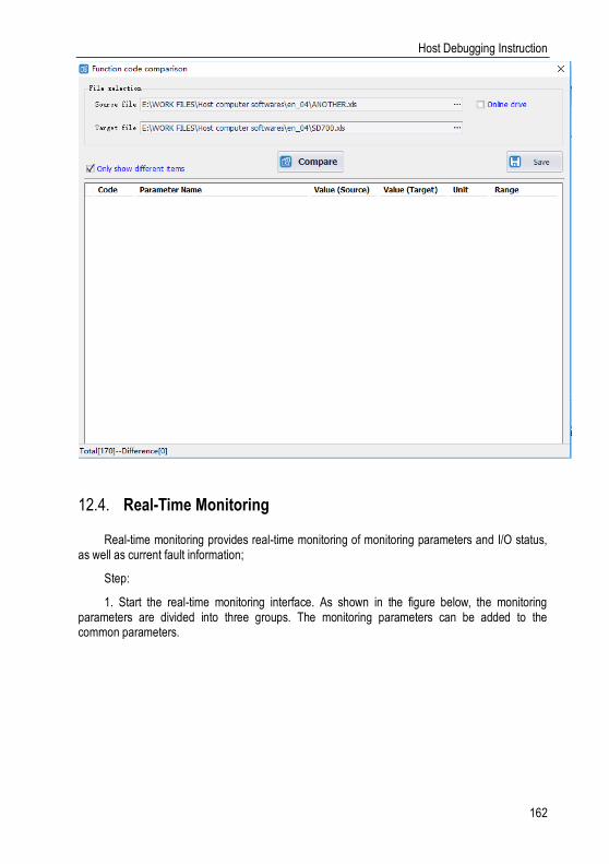
Host Debugging Instruction
162
Real-Time Monitoring 12.4.
Real-time monitoring provides real-time monitoring of monitoring parameters and I/O status, as well as current fault information;
Step:
1. Start the real-time monitoring interface. As shown in the figure below, the monitoring parameters are divided into three groups. The monitoring parameters can be added to the common parameters.
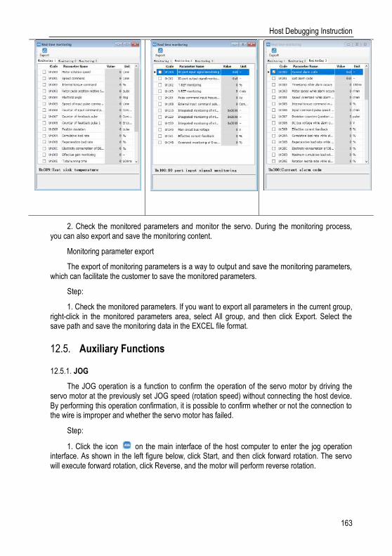
Host Debugging Instruction
163
2. Check the monitored parameters and monitor the servo. During the monitoring process, you can also export and save the monitoring content.
Monitoring parameter export
The export of monitoring parameters is a way to output and save the monitoring parameters, which can facilitate the customer to save the monitored parameters.
Step:
1. Check the monitored parameters. If you want to export all parameters in the current group, right-click in the monitored parameters area, select All group, and then click Export. Select the save path and save the monitoring data in the EXCEL file format.
Auxiliary Functions 12.5.
JOG 12.5.1.
The JOG operation is a function to confirm the operation of the servo motor by driving the servo motor at the previously set JOG speed (rotation speed) without connecting the host device. By performing this operation confirmation, it is possible to confirm whether or not the connection to the wire is improper and whether the servo motor has failed.
Step:
1. Click the icon on the main interface of the host computer to enter the jog operation interface. As shown in the left figure below, click Start, and then click forward rotation. The servo will execute forward rotation, click Reverse, and the motor will perform reverse rotation.

Host Debugging Instruction
164
Inertia Identification 12.5.2.
The inertia Identification function allows the servo unit to perform automatic operation (forward and reverse reciprocating motions), and estimates the moment of inertia of the load during operation.
Step:
1. Click [Inertia Identification]→[Next] on the host interface to enter the following interface in the inertia identification operation process, as shown in the following figure.

Host Debugging Instruction
165
2. As shown in the above figure, set the corresponding parameters according to the actual situation (usually keep the default), and click [Next] → [Write] → [Next] → [Enable] → [Forward] → [Reverse] After the forward rotation is repeated three times, the final inertia identification result is displayed, as shown in the following figure.
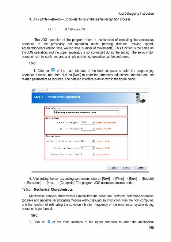
Host Debugging Instruction
166
3. Click [Write]→[Next]→[Complete] to finish the inertia recognition process.
1.1.1.1.1 12.5.3 Program JOG
The JOG operation of the program refers to the function of executing the continuous operation in the previously set operation mode (moving distance, moving speed, acceleration/deceleration time, waiting time, number of movements). This function is the same as the JOG operation, and the upper apparatus is not connected during the setting. The servo motor operation can be confirmed and a simple positioning operation can be performed.
Step:
1. Click on of the main interface of the host computer to enter the program jog operation process, and then click on [Next] to enter the parameter adjustment interface and set related parameters as required. The detailed interface is as shown in the figure below.
4. After setting the corresponding parameters, click on [Next] → [Write] → [Next] → [Enable] → [Execution] → [Next] → [Complete]. The program JOG operation process ends.
Mechanical Characteristics 12.5.3.
Mechanical analysis characteristics mean that the servo unit performs automatic operation (positive and negative reciprocating motion) without issuing an instruction from the host computer, and the function of estimating the common vibration frequency of the mechanical system during operation is performed.
Step:
1. Click on of the main interface of the upper computer to enter the mechanical

Host Debugging Instruction
167
characteristics analysis operation process, click on [Next] → [Next] to enter the parameter adjustment interface, and adjust the corresponding parameters according to the actual situation, as shown in the following figure.
2. Click [Next] → [Write] → [Next] → [Enable] → [Forward] → [Enable] → [Reverse] → [Next] → [Complete] to enter the mechanical properties FFT analysis interface, as shown in the figure below
2. From the above figure, you can analyze the frequency, amplitude, and phase of the
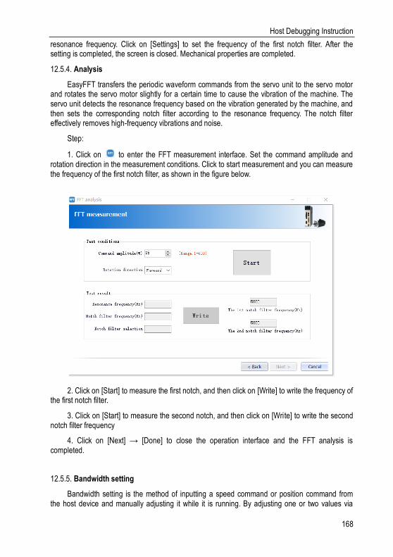
Host Debugging Instruction
168
resonance frequency. Click on [Settings] to set the frequency of the first notch filter. After the setting is completed, the screen is closed. Mechanical properties are completed.
Analysis 12.5.4.
EasyFFT transfers the periodic waveform commands from the servo unit to the servo motor and rotates the servo motor slightly for a certain time to cause the vibration of the machine. The servo unit detects the resonance frequency based on the vibration generated by the machine, and then sets the corresponding notch filter according to the resonance frequency. The notch filter effectively removes high-frequency vibrations and noise.
Step:
1. Click on to enter the FFT measurement interface. Set the command amplitude and rotation direction in the measurement conditions. Click to start measurement and you can measure the frequency of the first notch filter, as shown in the figure below.
2. Click on [Start] to measure the first notch, and then click on [Write] to write the frequency of the first notch filter.
3. Click on [Start] to measure the second notch, and then click on [Write] to write the second notch filter frequency
4. Click on [Next] → [Done] to close the operation interface and the FFT analysis is completed.
Bandwidth setting 12.5.5.
Bandwidth setting is the method of inputting a speed command or position command from the host device and manually adjusting it while it is running. By adjusting one or two values via
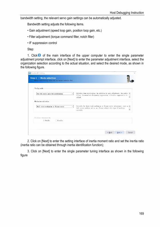
Host Debugging Instruction
169
bandwidth setting, the relevant servo gain settings can be automatically adjusted.
Bandwidth setting adjusts the following items.
• Gain adjustment (speed loop gain, position loop gain, etc.)
• Filter adjustment (torque command filter, notch filter)
• IF suppression control
Step:
1. Click of the main interface of the upper computer to enter the single parameter adjustment prompt interface, click on [Next] to enter the parameter adjustment interface, select the organization selection according to the actual situation, and select the desired mode, as shown in the following figure.
2. Click on [Next] to enter the setting interface of inertia moment ratio and set the inertia ratio (inertia ratio can be obtained through inertia identification function);
3. Click on [Next] to enter the single parameter tuning interface as shown in the following figure

Host Debugging Instruction
170
3. Click on [Adjust Start] to tune the tuning value (generally increase). During the process of increasing the tuning value, the servo will vibrate. At this time, vibration detection will be performed automatically. If not, operation can be performed manually, and the tuning value can be set in combination with the figure captured by the digital oscilloscope, or 80% of the tuning value of the motor can be selected as the tuning value. Specific or combined with the actual site requirements for adjustment settings.
4. In the tuning process, when the servo motor is vibrating, it will detect the resonance frequency and the intermediate frequency suppression frequency. After the tuning is completed, click on [Next] to enter the auto tuning completion interface and click on [Finish] to complete the single parameter adjustment operation.
Offset Adjustment 12.5.6.
Offset adjustment is divided into two parts:
1: Speed/torque command offset (automatic/manual) adjustment
2: Motor/current detection signal offset (automatic/manual) adjustment
Step:
1. Click on the main interface of the host computer to enter the offset wizard interface. Click on [Next] to enter the offset adjustment function selection interface, select the function you need to adjust, and click on [Next] to enter the adjustment interface.
2. Set the adjustment method, click on [Next], click on [Finish], the offset adjustment screen closes, and the adjustment process ends.
12.5.8 Back to Origin
The origin search is a function that determines the position of the origin pulse (Z phase) of the incremental encoder and stops at this position.
Step:
1. Click on the main interface of the host computer to enter the origin setting wizard
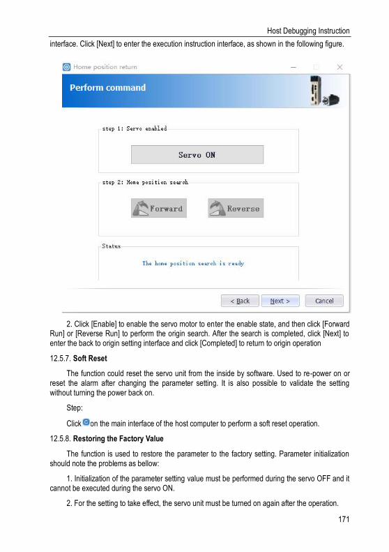
Host Debugging Instruction
171
interface. Click [Next] to enter the execution instruction interface, as shown in the following figure.
2. Click [Enable] to enable the servo motor to enter the enable state, and then click [Forward Run] or [Reverse Run] to perform the origin search. After the search is completed, click [Next] to enter the back to origin setting interface and click [Completed] to return to origin operation
Soft Reset 12.5.7.
The function could reset the servo unit from the inside by software. Used to re-power on or reset the alarm after changing the parameter setting. It is also possible to validate the setting without turning the power back on.
Step:
Click on the main interface of the host computer to perform a soft reset operation.
Restoring the Factory Value 12.5.8.
The function is used to restore the parameter to the factory setting. Parameter initialization should note the problems as bellow:
1. Initialization of the parameter setting value must be performed during the servo OFF and it cannot be executed during the servo ON.
2. For the setting to take effect, the servo unit must be turned on again after the operation.
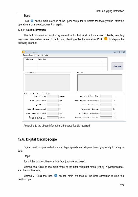
Host Debugging Instruction
172
Steps:
Click on the main interface of the upper computer to restore the factory value. After the operation is completed, power it on again.
Fault Information 12.5.9.
The fault information can display current faults, historical faults, causes of faults, handling
measures, information related to faults, and clearing of fault information. Click to display the following interface
According to the above information, the servo fault is repaired.
Digital Oscilloscope 12.6.
Digital oscilloscopes collect data at high speeds and display them graphically to analyze data.
Steps:
1, start the data oscilloscope interface (provide two ways):
Method one: Click on the main menu of the host computer menu [Tools] -> [Oscilloscope], start the oscilloscope;
Method 2: Click the icon on the main interface of the host computer to start the oscilloscope.
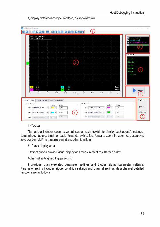
Host Debugging Instruction
173
3, display data oscilloscope interface, as shown below
1 - Toolbar
The toolbar includes open, save, full screen, style (switch to display background), settings, screenshots, legend, timeline, back, forward, rewind, fast forward, zoom in, zoom out, adaptive, zero position, dot/line , measurement and other functions
2 - Curve display area
Different curves provide visual display and measurement results for display;
3-channel setting and trigger setting
It provides channel-related parameter settings and trigger related parameter settings. Parameter setting includes trigger condition settings and channel settings; data channel detailed functions are as follows

Host Debugging Instruction
174
Data channel I/O channel
4 - Waveform display selection area
It provides selection and display of desired waveforms.
5 - Digital display of measured value
It provides display of current value, effective value, average value, maximum value, minimum

Host Debugging Instruction
175
value, peak value, etc.
6 - Record button operation button
It’s used to start and stop recording
7 - Collection method selection
It’s used to choose the mode of wave recording, real-time and triggered acquisition
Real-Time Acquisition 12.6.1.
Real-time acquisition is displayed in real time in the form of waveforms on the servo operating conditions.
Steps:
1. Start: Select real-time acquisition mode, set the channel settings, as shown in the figure
below, then click the record button , start recording, and the status of the icon changes to
,
2. Stop: click on the record button to stop recording, and the status of the icon
changes to .
Trigger Acquisition 12.6.2.
The trigger acquisition is based on the trigger condition and the acquisition cycle and makes the servo operation status displayed in the form of a waveform.
Steps:
1. Select the trigger for the acquisition mode. After the data channel and trigger conditions
are set, as shown in the following figure, click the record button , which triggers the start of recording.
Note: After setting the trigger condition parameters, the terminal receives the trigger condition and will automatically judge according to the conditions.
2. After the waveform to be triggered is received, the waveform will remain in the last state;
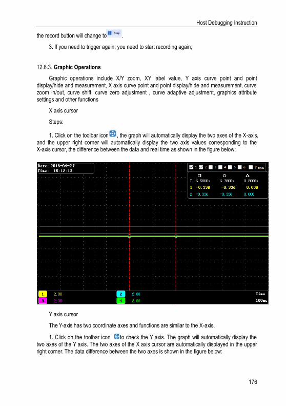
Host Debugging Instruction
176
the record button will change to .
3. If you need to trigger again, you need to start recording again;
Graphic Operations 12.6.3.
Graphic operations include X/Y zoom, XY label value, Y axis curve point and point display/hide and measurement, X axis curve point and point display/hide and measurement, curve zoom in/out, curve shift, curve zero adjustment , curve adaptive adjustment, graphics attribute settings and other functions
X axis cursor
Steps:
1. Click on the toolbar icon , the graph will automatically display the two axes of the X-axis, and the upper right corner will automatically display the two axis values corresponding to the X-axis cursor, the difference between the data and real time as shown in the figure below:
Y axis cursor
The Y-axis has two coordinate axes and functions are similar to the X-axis.
1. Click on the toolbar icon to check the Y axis. The graph will automatically display the two axes of the Y axis. The two axes of the X axis cursor are automatically displayed in the upper right corner. The data difference between the two axes is shown in the figure below:
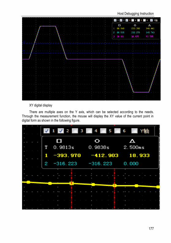
Host Debugging Instruction
177
XY digital display
There are multiple axes on the Y axis, which can be selected according to the needs. Through the measurement function, the mouse will display the XY value of the current point in digital form as shown in the following figure.

Host Debugging Instruction
178
Y axis scale display/hide
The Y coordinate scale is displayed as a fixed value, and the Y axis scale display/hide can be modified through the toolbar settings.
Steps:
1. Click the top right corner of the oscilloscope interface and and in the Y axis option, check the label visibility and scale visibility.
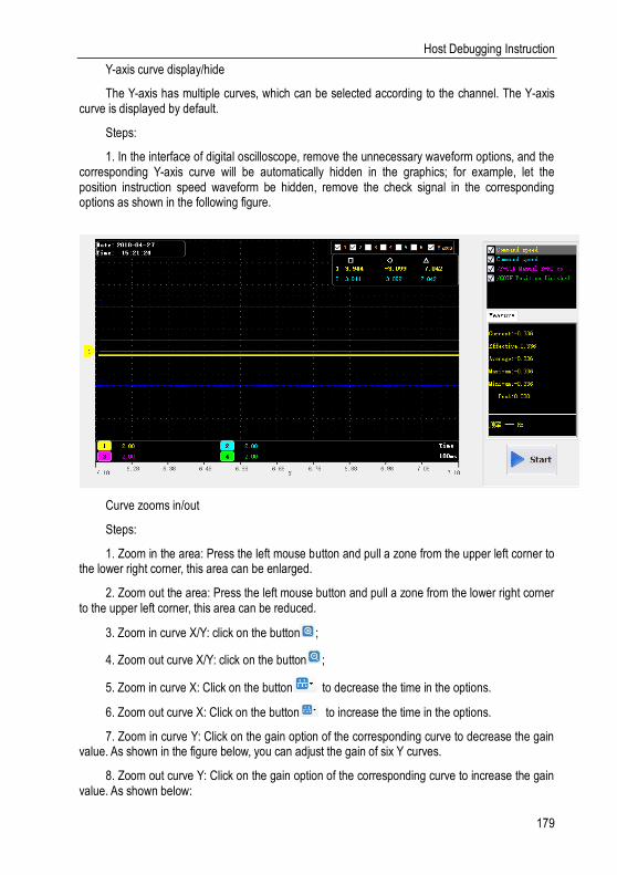
Host Debugging Instruction
179
Y-axis curve display/hide
The Y-axis has multiple curves, which can be selected according to the channel. The Y-axis curve is displayed by default.
Steps:
1. In the interface of digital oscilloscope, remove the unnecessary waveform options, and the corresponding Y-axis curve will be automatically hidden in the graphics; for example, let the position instruction speed waveform be hidden, remove the check signal in the corresponding options as shown in the following figure.
Curve zooms in/out
Steps:
1. Zoom in the area: Press the left mouse button and pull a zone from the upper left corner to the lower right corner, this area can be enlarged.
2. Zoom out the area: Press the left mouse button and pull a zone from the lower right corner to the upper left corner, this area can be reduced.
3. Zoom in curve X/Y: click on the button ;
4. Zoom out curve X/Y: click on the button ;
5. Zoom in curve X: Click on the button to decrease the time in the options.
6. Zoom out curve X: Click on the button to increase the time in the options.
7. Zoom in curve Y: Click on the gain option of the corresponding curve to decrease the gain value. As shown in the figure below, you can adjust the gain of six Y curves.
8. Zoom out curve Y: Click on the gain option of the corresponding curve to increase the gain value. As shown below:
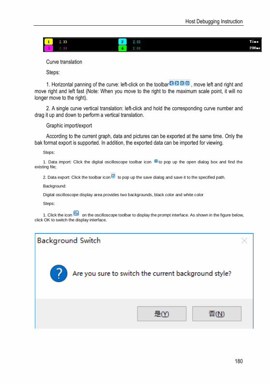
Host Debugging Instruction
180
Curve translation
Steps:
1. Horizontal panning of the curve: left-click on the toolbar , move left and right and move right and left fast (Note: When you move to the right to the maximum scale point, it will no longer move to the right).
2. A single curve vertical translation: left-click and hold the corresponding curve number and drag it up and down to perform a vertical translation.
Graphic import/export
According to the current graph, data and pictures can be exported at the same time. Only the bak format export is supported. In addition, the exported data can be imported for viewing.
Steps:
1. Data import: Click the digital oscilloscope toolbar icon to pop up the open dialog box and find the existing file;
2. Data export: Click the toolbar icon to pop up the save dialog and save it to the specified path.
Background:
Digital oscilloscope display area provides two backgrounds, black color and white color
Steps:
1. Click the icon on the oscilloscope toolbar to display the prompt interface. As shown in the figure below, click OK to switch the display interface.

Host Debugging Instruction
181
Others 12.7.
Window Display 12.7.1.
The window display is divided into: cascade, horizontal, vertical display, all off;
1. Cascade: click on the main menu of the host computer window [window] -> [cascade display];
2, level: click on the host computer interface menu bar [window] -> [horizontal display];
3, vertical: click on the main interface of the host computer menu window [window] -> [vertical display];
4. Close: Click on the main window of the host computer menu bar [Window] -> [Close all];
Help 12.7.2.
It provides servo debugging software version and other information.
Steps:
Click on the menu bar [help] -> [about], the software version information appears, as shown below