vehicular ad-hoc network based anti-theft model for car
TRANSCRIPT

i
Vehicular Ad-hoc Network based
Anti-theft
Model for car theft prevention in South
Africa
K Mawonde
orcid.org/0000-0002-7552-3549
Dissertation submitted in fulfilment of the requirements for the
degree Master of Science in Computer Science at the North West
University
Supervisors: Dr F Lugayizi
Dr B Isong
Graduation: July 2019
Student number: 23728949

ii
DECLARATION
I, KUDAKWASHE MAWONDE, hereby declare that this project report titled “Vehicular
Ad-Hoc Network Based Anti-Theft Model for Car Theft Prevention in South Africa” is my
own work carried out at North West University, Mafikeng Campus and has not been submitted
in any form for the award of a degree to any other university or institution of tertiary education
or published earlier. All the material used as source of information has been duly acknowledged
in the text.
Signature: ___________________ Date: ____________________
Kudakwashe Mawonde
APPROVAL
Signature: _____________________ Date: _____________________
Supervisor: Dr F. L. Lugayizi
Department of Computer Science
North West University
Mafikeng Campus
South Africa
Signature: _____________________ Date: _______________________
Co-supervisor: Dr. B. Isong
Department of Computer Science
North West University
Mafikeng Campus
South Africa.

iii
ACKNOWLEDGEMENTS
First and foremost, I would like to thank God for every blessing and lesson I have received in
my life, for it is the accumulation of all those experiences that has led me to this point and it
will continue to guide me as I progress. I offer acknowledgements to the following individuals
for helping me make this journey a success.
Secondly, I offer my astounding gratitude to my Supervisor Dr F. L Lugayizi and Co-
Supervisor Dr B. Isong for their incredible guidance and mentoring from the inception of this
work, to its completion. The insight they offered was crucial and insured success as an
inevitability. May God continue to bless them abundantly.
Special thanks to the Department of Computer Science and CSIR which afforded us all the
requirements we needed to complete this work, from suitable workstations to unrestricted
access to facilities.
Last but not least, I would like to thank my family for their overwhelming support throughout
this journey and their continued words of encouragement.

iv
ABSTRACT
Vehicle security is an area of major concern as indicated by the rate at which vehicles are stolen
in South Africa. This is evident from the statistics found on reputable government sites and
from the frequency at which people report stolen or hijacked vehicles. It also seems that despite
the various advances in technology accessible to the public, the thefts have not significantly
subsided, if at all.
The underlying problem is that vehicles on the road have inefficient security technology and
the new vehicles being manufactured are using variations of the old technology without
removing most of the weaknesses or using new technologies in the vehicles that in turn
introduce new ways in which perpetrators can compromise the security of the vehicles. Due to
this problem there is a need for a new approach in handling security which not only addresses
the problems of the past but ensures that no additional avenues are created through the
introduction of new technology. This will in-turn help in the development and introduction of
more robust security systems and technologies and further reduce the rate of successful vehicle
theft and hijackings.
This research attempts to address this security pandemic through the introduction of a new
security system based on networking, cryptography and biometrics that aims to safeguard the
vehicle through robust security mechanisms and bolster that with sensors to detect hardware
tempering. The system uses a One-Time Password implementation to ensure that security keys
are not reused and to prevent the capture of compromising information in the event of a data
transmission intercept. This is achieved through a simulation approach where the system
components are simulated in an effort to examine the effectiveness of the proposed system
using a multitude of mobile devices, a wireless network and different computers running
Windows and Linux to evaluate the results.
An analysis on the results was conducted where the controlled and uncontrolled variations of
the simulation were investigated. The results showed the shortfalls in the implementation in
the amount of information that the attacker was able to obtain however minimal and showed
the strength of the implementation in the robustness of the security and the abstraction of
critical data transmitted between the subsystems/ modules of the vehicle security system. It
also analysed the ineffectiveness of implementing an open network in such a security system.
From the simulations conducted we concluded that the system was effective in the tasks
intended and that it severely hampered the ability of a perpetrator compromising it through the
analysis of data transmissions and the use of captured data.
v
TABLE OF CONTENTS DECLARATION...................................................................................................................... ii
ACKNOWLEDGEMENTS .................................................................................................. iii
ABSTRACT ............................................................................................................................. iv
Chapter 1 .................................................................................................................................... 1
Introduction ................................................................................................................................ 1
1.1 Background and Motivation ............................................................................................ 1
1.1.1 Vehicular Ad Hoc Networks ..................................................................................... 2
1.1.2 Radio Frequency Identification ................................................................................. 4
1.1.3 Infrared ...................................................................................................................... 6
1.1.4 One Time Passwords................................................................................................. 6
1.2 Problem Statement ........................................................................................................... 7
1.3 Research Goal .................................................................................................................. 8
1.4 Research Questions .......................................................................................................... 8
1.5 Research Objectives ..................................................................................................... 8
1.6 Research Limitations ....................................................................................................... 8
1.7 Research Contributions .................................................................................................... 9
1.8 Research Methodology .................................................................................................... 9
1.9 Research Outputs ........................................................................................................... 10
1.10 Thesis Outline .............................................................................................................. 11
Chapter 2 .................................................................................................................................. 12
RELATED Literature............................................................................................................... 12
2.1. Chapter Outline ............................................................................................................. 12
2.2. Introduction and Background ....................................................................................... 12
2.3. Overview of Security .................................................................................................... 18
2.3.1 Related Works on Vehicle theft and Vehicle Security ........................................... 18
2.4. Technologies used for Car Theft Prevention and Tracking .......................................... 23
2.4.1. Radio Frequency Identification .................................................................................. 24
2.4.2 Bluetooth ..................................................................................................................... 29
2.6. Vehicular Ad hoc Networks.......................................................................................... 31
2.7. Normal Networks (Wi-Fi Direct).................................................................................. 32
2.8. Network Infrastructure Selection – Normal networks vs. VANETS ............................ 35
2.9. One Time Passwords..................................................................................................... 35
2.10. Biometric Authentication ............................................................................................ 37
2.11 Critical Literature Review............................................................................................ 38
vi
2.12 Chapter Summary ........................................................................................................ 38
Chapter 3 .................................................................................................................................. 39
Research Methodology and Materials ..................................................................................... 39
3.1 Chapter Outline .............................................................................................................. 39
3.2 Methodology and Design ............................................................................................... 39
3.3 Methods and Techniques ............................................................................................... 41
3.3.1 System Overview .................................................................................................... 41
3.3.2 System Analysis ...................................................................................................... 42
a) System Requirements Process ............................................................................... 42
b) System Requirements Specification ...................................................................... 43
3.3.3 System Modelling ................................................................................................... 47
3.3.4 Use Case Model .......................................................................................................... 47
a) Actors..................................................................................................................... 47
b) Actor Roles ............................................................................................................ 49
c) Use Cases ............................................................................................................... 50
d) Use Case Description............................................................................................. 52
3.3.5 Sequence Diagrams ..................................................................................................... 62
3.3.6 Activity Diagrams ....................................................................................................... 66
3.3.7 System Design ............................................................................................................ 68
a) System Architecture .............................................................................................. 68
b) Components Detailed-Design and Requirements .................................................. 70
3.3.8 Network Architecture.................................................................................................. 75
3.3.9 System Algorithmic Design ........................................................................................ 77
a) The KEY algorithm ............................................................................................... 78
b) The CARSEC algorithm ........................................................................................ 82
c) The BLACKBOX .................................................................................................. 84
3.3.10 System Security ........................................................................................................ 86
3.3.11 Chapter Summary ..................................................................................................... 86
Chapter 4 .................................................................................................................................. 87
Simulation Setups and Experiments ........................................................................................ 87
4.0 Chapter Outline .............................................................................................................. 87
4.1 Introduction .................................................................................................................... 87
4.2 Focus and Scope ............................................................................................................ 89
4.3 Description of Overall Setup ......................................................................................... 90
4.4 Modules Description ...................................................................................................... 92

vii
4.4.1 The Wireless Network Adapter .............................................................................. 92
4.4.2 CARSEC ................................................................................................................. 92
4.4.3 KEY ........................................................................................................................ 93
4.4.4 Attacker Device ...................................................................................................... 93
4.5 Setting up of Individual Modules .................................................................................. 94
4.5.1 Wireless Network Adapter ...................................................................................... 94
4.5.2 CARSEC ................................................................................................................. 95
4.5.3 KEY ........................................................................................................................ 95
4.5.4 Attacker Device ...................................................................................................... 98
4.6 Simulation Setup ............................................................................................................ 99
4.6.1 Network Setup ........................................................................................................ 99
4.6.2 Setup of Attacker Device ...................................................................................... 101
4.6.3 Generation and transmission of the password ...................................................... 103
4.6.4 Capturing of traffic by Attacker Device ............................................................... 105
4.7 Test Parameters ............................................................................................................ 106
4.8 Testing Environments .................................................................................................. 109
4.8 Chapter Summary ........................................................................................................ 115
Chapter 5 ................................................................................................................................ 116
Results and Discussion .......................................................................................................... 116
5.1 Chapter Outline ............................................................................................................ 116
5.2 Simulation Results – Controlled Variation .................................................................. 116
5.3 Simulations Results – Uncontrolled and Secure Variation .......................................... 128
5.4 Simulation Results – Uncontrolled and Open Variation.............................................. 139
5.5 Evaluation and Discussion ........................................................................................... 144
5.6 Chapter Summary ........................................................................................................ 145
Chapter 6 ................................................................................................................................ 146
Conclusion and Future Work ................................................................................................. 146
6.1 Chapter Outline ............................................................................................................ 146
6.2 Summary ...................................................................................................................... 146
6.3 Conclusion ................................................................................................................... 147
6.4 Future Work ................................................................................................................. 147
REFERENCES ...................................................................................................................... 148

viii
TABLE OF FIGURES
Figure 1.1 Chart showing car and motorcycle theft from 2005 to 2016 [1]……………………1
Figure 1.2 Illustration of VANETs [12]………………………………………………………..3
Figure 1.3 Diagrammatic representation of RFID [4]…...………………………………...…..5
Figure 2.1 Most stolen passenger vehicle brands [26]…………………………………….…..15
Figure 2.2 Most stolen SUV brands [26].………………………………………………….....16
Figure 2.3 Most stolen Manufacturer truck brands [26]………………………………….…..17
Figure 2.4 Diagrammatic representation of RFID communication mechanism [3]………….25
Figure 2.5 The Bluetooth Protocol Stack [60]…………………………………………….....30
Figure 3.1 Proposed Research Work sequence……………………………………………....40
Figure 3.2 System actors…………………………………………………………………......48
Figure 3.3 VANET Antitheft system use case diagram…………………………………...…51
Figure 3.4 Antitheft System Sequence Diagram………………………………………...…...63
Figure 3.5 Antitheft System Activity diagram…………………………………………...…..67
Figure 3.6 System Architecture…………………………………………………………...….69
Figure 3.7 System Component Design…………………………………………………….....71
Figure 3.8 Network Architecture…………………………………………………………......76
Figure 3.9 KEY algorithm to register fingerprint………………………………………..……79
Figure 3.10 Algorithm showing the normal operation of the KEY…………………………..81
Figure 3.11 Algorithm detailing how the CARSEC functions…………………………….....83
Figure 3.12 Algorithm showing how the BLACKBOX part of the system operates……..….85
Figure 4. 1 Diagrammatic representation of Experiment setup……………………………....91
Figure 4. 2 Wireless Network Adapter…………………………………………………..……92
Figure 4. 3 CARSEC……………………………………………………………………..…..93
Figure 4. 4 KEY…………………………………………………………………………..….93
Figure 4. 5 Attacker Device……………………………………………………………….....94
Figure 4.6 Secure wireless communication setup on the Wireless Network adapter
module……………………………………………………………………………………….94
Figure 4. 7 Syncthing on CARSEC………………………………………………………….95
Figure 4. 8 Syncthing configured on the KEY module…………………………………..…..96
Figure 4. 9 Syncthing connected from CARSEC to KEY………………………………..…..96

ix
Figure 4. 10 AndOTP running on the KEY module……………………………………..……97
Figure 4. 11 KEY uses shared password to encrypt password file………………………..….98
Figure 4. 12 Attacker device running a live version of Kali Linux……………………..……98
Figure 4. 13 CARSEC connected to the closed secure wireless network………………….....99
Figure 4. 14 KEY connected to the closed secure wireless network…………………..…….100
Figure 4. 15 checking wireless interfaces………………………………………………..…..101
Figure 4. 16 checking the capabilities of the wireless adapter……………………………….101
Figure 4. 17 setting promiscuous mode on………………………………………………..…101
Figure 4. 18 configuring a monitoring interface…………………………………………..…102
Figure 4. 19 Confirming the monitor interface is active…………………………………..…102
Figure 4. 20 Scanning for networks…………………………………………………………102
Figure 4. 21 Results of Network Scanning…………………………………………………..102
Figure 4. 22 Isolate channel of interest and capture traffic…………………………………103
Figure 4. 23 Capture isolated network traffic……………………………………………….103
Figure 4. 24 TOTP generation by AndOTP………………………………………………….103
Figure 4. 25 Encrypted file containing password……………………………………………103
Figure 4. 26 KEY syncing encrypted password file with CARSEC………………………...104
Figure 4. 27 CARSEC syncing encrypted password file from KEY………………………..104
Figure 4. 28 captured activity on the closed secure network………………………………...105
Figure 4. 29 Captured traffic from closed secure network in Wireshark…………………….105
Figure 4. 30 Diagrammatic representation of Simulation parameters……………………….107
Figure 4. 31 Elevated data access level in the first scenario…………………………………110
Figure 4. 32 Captured transmission of closed secure network from Attacker Device……….112
Figure 4. 33 Captured traffic on open wireless network……………………………………..114
Figure 5. 1 Data transmissions directly from the CARSEC module of the vehicle security
system………..…………………………………………………………………...................117
Figure 5. 2 Cryptographic key exchange between the Syncthing clients on KEY and
CARSEC…………………………………………………………………………………... 119
Figure 5. 3 TCP Stream of encrypted transmissions between the KEY and CARSEC
Modules… ………………………………………………………………………………….121
Figure 5. 4 Throughput and Segment length………………………………………………..123

x
Figure 5. 5 Zoomed in version of Throughput and segment length graph………………….125
Figure 5. 6 Round Trip Time…… ………………………………………………………….127
Figure 5. 7 Traffic from vehicle security system………………………………………….....129
Figure 5. 8 capture statistics from attacker's device……………...……………………….....131
Figure 5. 9 Captured transmissions of KEY on the vehicle wireless network…………..…..133
Figure 5. 10 Captured transmissions of CARSEC on the vehicle wireless network……..….135
Figure 5. 11 Captured wireless network handshake on attacker's device…………………….137
Figure 5. 12 traffic from a vehicle security system using an open network……………..…..140
Figure 5. 13 Captured data transmissions from the vehicle security network using
an open wireless network…………………………………………………………………....142

xi
LIST OF TABLES
Table 2.1 Hijacking Statistics for 2016/2017…………………………………………………13
Table 2.2 Vehicle Theft Statistics for 2016/2017…………………………………………….14
Table 3.1 KEY Requirements………………………………………………………………...44
Table 3.2 CARSEC Requirements……………………………………………………………45
Table 3.3 BLACKBOX Requirement Priorities……………………………………………...46
Table 3.4 Actors and Roles…………………………………………………………………...49
Table 3.5 Receive response from KEY and Generate challenge……………………………..53
Table 3.6 Unlock Vehicle functions………………………………………………………….55
Table 3.7 Send log data to BLACKBOX…………………………………………………….56
Table 3.8 Unauthorized access and or tampering…………………………………………….57
Table 3.9 Register biometrics………………………………………………………………...58
Table 3.10 Read and authenticate fingerprint………………………………………………...59
Table 3.11 Generate One Time Password…………………………………………………….60
Table 3.12 Transmit encrypted log data………………………………………………………61

xii
LIST OF ACRONYMS
AES Advanced Encryption Standard
API Application Program Interface
CAN Controlled Area Network
DOS Denial of Service
DST Digital Signal Transponders
ECDH Elliptical Curve Diffie Hellman
ECMQV Elliptical Curve Menezes-Qu-Vanstone
ECU Electronic Control Unit
ESSID Extended Service Set Identification
GHz Gigahertz
GIN Group Identification Number
GM Group Member
GO Group Owner
GPS Global Positioning System
GSM Global System for Mobile communication
HMAC Hash Message Authentication Code
IEEE Institute of Electrical and Electronics Engineers
IM Instant Message
IoT Internet of Things
IR Infrared
ITS Intelligent Transport Systems
LC Legacy Client
LED Light Emitting Diode
LPR Licence Plate Recognition

xiii
MAC Media Access Control
MANET Mobile Ad Hoc Network
MD4 Message-Digest 4
MD5 Message-Digest 5
NSA National Security Agency
OBU On-Board Unit
OTP One Time Password
PIN Personal Identification Number
QoS Quality of Service
RFID Radio Frequency Identification
RFID Radio Frequency Identification
RSU Road Side Unit
SHA Secure Hash Algorithm
SoC System on Chip
SPU Secure Processing Unit
SSID Service Set Identifier
SUV Sports Utility Vehicle
TLS Transport Layer Security
TOTP Time based One Time Password
UHF Ultra High Frequency
V2I Vehicle to Infrastructure
V2V Vehicle to Vehicle
VANET Vehicle Ad Hoc Network
VIN Vehicle Identification Number

xiv
WPA2-PSK Wi-Fi Protected Access 2 Pre-Shared Key

1
CHAPTER 1
INTRODUCTION
1.1 Background and Motivation
Motor Vehicles (here forth referred to simply as “Vehicles”) as a source of transportation have
helped the human race advance in numerous ways by offering convenient and reliable
transport. They have enabled people to travel long distances in short spaces of time at a fraction
of what it would cost to accomplish the same feat using air travel so it is no surprise that these
motorized objects have become an intricate part of our lives through personal vehicles and
public transport. With the increased popularity and use of vehicles, there has also been a need
to consistently improve them in all aspects from performance, safety, stability and security.
Sadly with all advancements, car theft is still prevalent, as evidenced with the number of car
thefts or car robberies that occur every year. Figure 1.1 presented in [1] showed yearly car theft
estimates in South Africa from 2005 to 2016.
Figure 1.1 Chart showing car and motorcycle theft from 2005 to 2016 [1]
Whilst the chart shows a gradual decrease in the yearly figure of crimes, the number of
vehicular thefts is still alarmingly high and a cause for concern. Infrared [2], used to be the
technology used to secure vehicles through remote means but with limitations such as the need

2
for line of sight for a signal to be transmitted successfully, there was a need for the development
of a more convenient communication standard which was more robust. Current car security is
based on active Radio Frequency Identification (RFID)[3] technology which enables the
inclusion of device specific data and increases transmission capabilities. A study by Chawla et
al., [4] highlighted concerns in RFID as certain implementations have compromised the
security of the technology in favour of convenience and low cost, making counterfeiting of
security keys possible and in some cases successful.
Given the critical limitations posed by RFID, it is worth investigating alternative technology
which can mitigate the probability of successful car theft, if at all, and one such approach comes
through the use of Vehicular Ad-hoc Network (VANETs) technology. VANETs are a vehicle
specific technology built from Mobile Ad-hoc Networks (MANETs) which are general purpose
distributed self-configuring wireless networks built from nodes that do not rely on a centralized
hub to facilitate intercommunication [5]. Normally the use of this technology has been to
facilitate inter-vehicle communication but in this particular instance, it can be used in vehicle
security through the creation of a closed and encrypted network between the vehicle as a node
and the wireless key as the second node. The key would use a one-time password system to
generate a unique and temporary key that is encrypted and transmitted to the vehicle and
matched against the key generated by the identical one-time password system in the vehicle.
1.1.1 Vehicular Ad Hoc Networks
VANETs, as shown in Figure 1.2, are a special class of MANETs [5, 6] in which vehicles
facilitate communication with each other by acting as independent and fully functional network
nodes. These nodes form a fully autonomous and self-configuring network that does not need
a centralized control node to route information between them. Due to the additional factors
such as high mobility and random driver behavior, VANETS operate in slightly different
manner in comparison to MANETS. VANETS use the 5.9 GHz frequency, as detailed by
Armstrong et al., [7] which enables vehicles to communicate with each other (Vehicle to
Vehicle) and with infrastructure (Vehicle to Infrastructure). This technology is used to increase
the basic usefulness of a vehicle by providing enhanced safety information for the driver,
entertainment for the occupants of the vehicle through networked media and general
comfort[8].

3
Figure 1.2 Illustration of VANETs[9]

4
1.1.2 Radio Frequency Identification
Radio Frequency Identification (RFID) is a technology that operates through the use of a
transceiver communicating with a reader when the two devices are in range of each other as
illustrated in Figure 1.3. This results in the reader obtaining information about the transceiver
that identifies the transceiver. RFID tags fall under passive, semi-passive and active [4].
Passive tags do not have a power source so they use the electromagnetic field created by the
reader to power up and a process called backscattering to transmit information to the reader
[4]. Semi-passive tags have their own power sources but they also use backscattering to
transmit information to the reader. The active tag is the one set apart as it has its own power
source and transmitter. RFID technology has been implemented in vehicle security through the
embedding of the transceiver in the keys or vehicle remote and the integration of the reader
with the vehicle’s locking system creating a secure remote locking system which is encrypted
[10]. However the information transmitted between the key and the vehicle is susceptible to
interception and misuse since the energy used is not enough to fully power encryption circuits
and therefore limits the use of full-strength keys [4]. Authors in [11] described a device that
would only serve to further circumvent inbuilt security offered by RFID technology, were it to
fall in the hands of an adversary, by compromising the security of the data embedded in a
device.

5
Figure 1.3 Diagrammatic representation of RFID[4]
6
1.1.3 Infrared
Infrared is to a shortwave electromagnetic signal that is used for short range transmissions.
Labonde [2] proposed the use of IR in a vehicle security system that uses a mobile transponder
in the form of a key or a portable device carried by the driver which receives a coded
interrogation signal from the vehicle and sends back a coded answer signal. The signal is
validated by the car and the vehicle unlocks the doors electronically. This technology however
falls short in the transmission range and security mechanisms that are applied to the transmitted
codes, which are nonexistent thereby making the system vulnerable to code interception or
even device cloning.
1.1.4 One Time Passwords
One Time Passwords are an authentication system used to circumvent eavesdropping [12] and
capturing of sensitive authentication information on a network through the use of a temporary
password that is encrypted. The concept was originated by Bellcore [13] and most, if not all,
forms of modern adaptations have evolved from that. Haller et al., [12] detailed how the
security of an OTP system is dependent non-invertible secure hash functions such as the ones
found in MD4 [14], MD5 [15] and SHA [16] algorithms. The system uses session specific
information between the user and the server to generate a unique password by combining the
user’s secret key and session specific information as part of the challenge used to generate the
password. Generation sequences are synced through the use of a password sequence number
with details of the last successful login [12]. Lamport [17] proposed that when the challenge is
created through the use of the user’s secret key and the seed or session specific information
produced by the server, it is run through the hash function multiple times before a one-time
password is generated. The password is then verified when the server generates a password by
running the hash function once and comparing it to the previously valid password. Guski et al.,
[18] proposed the combination of time-dependent information with non-time-dependent
information to create the authentication parameter which can later be inversed for verification
purposes at the authenticating node, eliminating the need for password regeneration at the
authenticating node but this however contrasts the non-invertible properties of the system.
There have been numerous vehicle security proposals over the years like the one by Berman et
al.,[19] in which they suggested the input of a secret initiation sequence that activated the
vehicle functions but the limitations of this technology come in the lack of authentication, as
anyone with the knowledge of the secret sequence can disable the system. In another article

7
[20], a keypad was proposed, in combination with the use of a remote signalling module which
increases security but falls short in the use of a recognizable pattern in the form of the key code.
The predominant technology used in vehicle security is RFID with some variation of a rolling
code mechanism to create a pseudorandom sequence of validation keys but this has been
circumvented through the use of a capture device that records the transmitted codes and uses
them in a replay attack. The model proposed in this thesis aims to eliminate that vector of attack
through the use of an encrypted OTP system that uses random keys between the vehicle and
the key, as well as device specific information to authenticate the user.
1.2 Problem Statement
The recent vehicle theft statistics [1] indicate that despite the improvements made on vehicle
security, vehicles are still being stolen and this is problematic in that it indicates a possible
vulnerability with the current technology used to secure vehicles. The implementation of RFID
technology [3] in remote locking of vehicles and antitheft devices [4] has resulted in a decrease
in technical vulnerabilities due to the increased complexity of the system. RFID is more
convenient than Infrared [2] since it does not require line of sight for it to be functional. The
shortcomings of RFID arise from the manner in which the technology is implemented, since it
sends a code to the receiver located on the vehicle for verification, be it a fixed or rolling code
[21] and does not send any sort of feedback or response to the transmitter, making it susceptible
to replay attacks [22] from a technical adversary who can successfully block the original signal
transmitted from the genuine transmitter and copy the code or encoded information being
transmitted to the vehicle for later use. This makes vehicles secured with RFID technology
susceptible to theft by a technically inclined adversary and it is for this reason that a more
robust approach be implemented to mitigate the vulnerabilities in vehicles and further ensure
security. This is not to say that vehicle theft can be solely attributed to vulnerabilities found in
remote systems, since there are a myriad of ways in which perpetrators can compromise
security including, but not limited to, the theft of the original remote/ transmitter or a robbery.
However, securing of the transmission between the remote/ transceiver against interception or
man-in-the-middle attacks[23] reduces the avenues with which a perpetrator may conduct an
attack.
The shortcomings of the technologies currently implemented in vehicle security warrant an
investigation into more robust theft countermeasures that will further secure vehicles and this
research aims to propose such a counter measure.
8
1.3 Research Goal
The main aim of this research is to design a VANET-based anti-theft model for car theft
prevention in South Africa.
1.4 Research Questions
The main research question prompts enquiry into the possible development of alternative
vehicle security systems that address the current and inherent weaknesses found in pre-existing
systems. Further analysis results in the questions formulated later in this subsection.
To meet the aim of this research, the following questions (RQ) can be asked:
RQ1: What existing technologies are effective in the prevention of car theft?
To answer this question, the following sub questions are answered.
RQ1.1: What technologies are currently used in vehicle security?
RQ1.2: What are the limitations of the technologies currently implemented in vehicle
security?
RQ2: How can we design a secure car theft prevention system to combat stolen vehicles in
South Africa?
RQ3: How can one implement and evaluate the system in RQ2?
1.5 Research Objectives
To meet the aim of this research, the following research objectives (RO) will be performed:
RO1: Investigate the trends in car theft, technologies used in car security and VANETs.
RO2: Design vehicle theft prevention system using the suitable technology
RO3: Implement and evaluate the designed system in ii.
1.6 Research Limitations
The limitations in this research are mainly on RO3 listed in Section 1.5 above and they affect
the system in the manner detailed below:
a) Functional components of the system were tested and evaluated individually in order
to offer a clearer picture at the stages where a potential compromise of the system would
occur.

9
b) The system was simulated and evaluated on a 2.4 GHz wireless network for simplicity
as the other devices which were used in the simulation are able to communicate on this
band instead of a custom band.
c) The encryption and security of the transmissions were the factors used to evaluate the
effectiveness of the system.
d) There were only three variations of the simulations that were conducted as they were
determined sufficient to provide clarity on the research objectives namely a secure
closed network control, an open network control and a controlled variation to compare
the results of the first two against (each other).
e) Network stability was also tested and its evaluation was limited to round trip time,
throughput and segment length.
f) The One Time Password and data encryption were demonstrated in simulation but not
evaluated as the display was deemed sufficient in relation to the overall functionality
of the system.
g) The black box aspect of the system is excluded from the simulations since it is
considered lower priority in terms of functionality.
1.7 Research Contributions
This research aims to provide a solution, or at the very least, foresight into new avenues that
can be explored in the pursuit of advancement in vehicular security technology. This will aid
other researchers in refining or evolving the research into more complex systems which offer
even more efficiency without any drawbacks that exist in the currently implemented
technology and without introducing additional vectors that can be manipulated by adversaries
and this is achievable through proper implementation of the security systems.
The research also aims to aid manufacturers in the consideration of more advanced security
mechanisms that cannot be compromised by traditional means like their current technology
and it introduces the possible use of biometrics as a sophisticated and non-invasive
implementation of antitheft in their next generation vehicles.
1.8 Research Methodology
In order to obtain valid and reliable results for this study, the simulation research method was
used to model varied situations in which the same data of interest was obtained and analysed.
The data obtained had two facets of analysis and therefore a mixed approach was used in the
analysis of the resulting data in order to achieve the intended primary goals.

10
The mixed method of analysis involves the use of both quantitative and qualitative analysis to
obtain information from the results obtained in the simulation. These methods are used in
parallel to obtain more comprehensive results based on statistical and observational data.
1.9 Research Outputs
During the course of this research, a paper titled “A Survey on Vehicle Security Systems:
Approaches and Technologies” was produced and published to IECON18 which offered a
detailed look into the state of currently implemented vehicle security technologies and assessed
their strengths and weaknesses.
11
1.10 Thesis Outline
This research will be organized as follows:
Chapter 1 is the introduction of the research where the underlying problem is
described in detail in order to provide a clear picture of the areas that need
addressing. The goal is highlighted in this chapter as well as the questions that
can be asked to formulate objectives that aid in achieving the said goal. An
initial literature review is conducted which highlights some of the areas of
importance in the research. The scope and limitations of the research are also
detailed in this chapter.
Chapter 2 is the literature study that contains a comprehensive detail of all the
areas of focus in this research including the investigation into currently
implemented technologies and a look into the alternative technologies currently
under development. An exploration into the shortcomings of existing
technologies is also conducted and it is followed by a look into potential
technologies that can be used to bolster current security.
Chapter 3 details the system that is being proposed. It covers aspects of the
system in detail including but not limited to the network and system design and
architecture, the proposed hardware components layout and design and the
functional and non-functional specifications. It details the way in which the
system is to function and details various functional features in the system.
Chapter 4 is where the system is implemented through simulation by using
multiple computers and mobile devices to represent the components of the
system, namely the vehicle and the key. Two more devices are used to represent
the network module and the device used by the attacker to monitor and capture
transmitted data.
Chapter 5 discusses the results obtained in Chapter 4 and evaluates the results
from the different components in relation to the overall system. It also discusses
the results of the network stability.
Chapter 6 summarizes the research, provides conclusions based on the results
obtained in Chapter 5 and brings forth recommendations on what can be done
as future work and how the system can further be improved.
12
CHAPTER 2
RELATED LITERATURE
2.1. Chapter Outline
This chapter will explore the nature of vehicle theft in detail to determine the elements in which
this crime occurs and look at previous works that have investigated this phenomenon in detail
to provide a complete picture of the severity and scope of the problem faced by everyday
motorists in their daily commute. The chapter will also investigate the technologies that are
currently implemented in vehicles both old and new and the ways in which these technologies
provide security and function as well as the shortcomings of the currently implemented
technology with an indication of how these weaknesses are used by perpetrators to circumvent
these security measures. This chapter will contain a section on technologies that can be used in
the proposed solution under study in this thesis. A look into alternative security approaches
will be conducted, in which technologies such as passwords and biometrics will be assessed.
2.2. Introduction and Background
Vehicle security has consistently been a major concern for vehicle manufacturers around the
globe. Although this is a common occurrence with varying levels from country to country there
are places like South Africa where the rate at which thefts and hijackings occur is severely high
with some unfortunate cases resulting in the fatality of the driver and passengers.
According to Africa Check [24] an estimated 52 307 cars or motorcycles were stolen in the
2017 year with a daily average of 146 thefts, which is a decrease from the 53 809 for 2016.
Such alarming figures raise questions on the motivations of such events and concerns on the
effectiveness of the security implemented in the vehicles currently on the road. The same
source also lists vehicle theft as the second highest type of crime reported to the police in the
country at a staggering 94% and second only to murder which is at 98%.
A survey by CarTrack [25] shows a more detailed description of the hijackings and vehicle
thefts per province per province as shown in the figures below.

13
Table 2.1 Hijacking Statistics for 2016/2017[25]
The data in the Figure 2.1 above and Figure 2.2 below clearly indicate that the Gauteng
province experiences the highest hijackings in the country then KwaZulu Natal and next it is
Western Cape being the top three provinces. Incidentally, the three named provinces also house
the biggest cities in the country with Gauteng having two (Johannesburg and Pretoria) which
could mean that criminals are more concentrated or active in large metropolitan areas.

14
Table 2.2 Vehicle Theft Statistics for 2016/2017[25]
Vehicle theft is also predominant in provinces with major cities with Gauteng taking the lead
and Western Cape being a close second.
CarTrack, a vehicle tracking company released its statistics for the most hijacked and stolen
car brands in three segments, Passenger vehicles, Sports Utility Vehicles (SUVs) and trucks
[26] as shown in figures below.

15
Figure 2.1 Most stolen passenger vehicle brands[26]
According to the Figure 2.3 above, Volkswagen owners suffer the most losses as they are the
highest number of victims with a focus made on the Polo model owners. They cover 35% of
total vehicle thefts and highjackings. Toyota is a close second, accounting for 18% of total
passenger vehicle thefts.

16
Figure 2.2 Most stolen SUV brands[26]
In the SUV segment, as shown in Figure 2.4 above, Toyota owners suffer the heaviest losses
as drivers of the Fortuner model are particularly targeted the most with a 55% of all SUV thefts
and hijackings. Land Rover owners are second on the list with a 10%.

17
Figure 2.3 Most stolen Manufacturer truck brands [26]
For trucks as shown in the Figure 2.5 above, the order of hijacked or stolen brands is Nissan,
Scania and Freightliner with percentages of 23, 16 and 15 respectively.
All of these different vehicle types use different security mechanisms on top of the traditional
lock and key but despite the numerous technologies implemented in these vehicles, the rate of
theft and hijacking is still substantially high.
The above statistics indicate that there is a severe deficit in the security technologies currently
implemented and they further warrant an investigation of the predominantly used vehicle
security technologies and weaknesses, as well as a study of new technologies or combination
thereof, that can be used to cover the gaps created by current technology and to mitigate the
loss of motor vehicles through theft or hijacking.
18
2.3. Overview of Security
This section offers a comprehensive study into the current security implementations as well as
other security related studies.
2.3.1 Related Works on Vehicle theft and Vehicle Security
Vehicle theft is a global menace and as such, professionals from different fields have worked
tirelessly and studied causes of the high rates at which these thefts occur from sociological
patterns which hint at the motive of theft to technological vulnerabilities which present attack
surfaces for threat actors to use in illegally accessing vehicles. A study by Copes et al [27] used
crime-specific models to investigate the way in which vehicle theft rate varied according to the
availability of targets, population activity and supply of potential offenders and concluded that
various factors affect the rate of vehicle theft, including but not limited to, availability of the
vehicles, size of the offender pool, how easy it is to conceal the stolen vehicle and the kind of
protection offered in the vicinity where the vehicle is located. Their study also showed that
certain passenger vehicles were selected due to their level of security. Newman [28] studied
and provided work on how development of many of current car technologies was in response
to vehicle related crimes, for example, keys were developed as rudimentary immobilizers
meant to prevent unauthorised access and use of vehicles, license plates were developed and
mandated to reduce the anonymity of vehicles which were similar in model, make and
specifications. Mechanical immobilizers were also developed in the 1950s but they proved to
be easily overcome by perpetrators. Electronic immobilizers were then developed to combat
the short comings of mechanical immobilisers and they worked by interrupting fuel and
ignition systems [29]. Door lock technology evolved as well offering a more robust and discrete
placement of the locking mechanisms and it was augmented by the development of remote
locking which used encrypted radio frequency identification devices.
In a similarly themed study by Farrel et al. [30] investigated the decrease in vehicle theft in the
United Kingdom in the mid-90s and attributed it to the improvements that had been made in
vehicle security. They developed a tool to analyse the effectiveness of different security
technologies when implemented together and ranked the different security device combinations
to determine which combination offered the highest protection factor. The summation from
that study was that the combination of central locking and electronic immobilisers was crucial
in every configuration and additional technologies such as alarms and trackers were beneficial
to the security of the vehicle as well.

19
The unescapable fact is that despite the advancements made by the vehicular industry to ensure
the minimisation of vehicle theft through continuous development and improvement of existing
security solutions, attackers and perpetrators have continuously proved to be resourceful in
attaining the knowhow required to compromise these systems. This statement stands true for
different types of technology from mechanical locks to electrical locks and even trackers. This
has led to the inevitable conclusion that for security breaches in vehicles to be mitigated, there
is a need to explore newer technologies and to conduct different approaches in how security is
handled.
Lui et al. [31] proposed an internet of things (IoT) based vehicle anti-theft tracking system in
which he used technologies such as global system for mobile communication (GSM) and global
positioning system (GPS) in conjunction with radio frequency identification (RFID), vibration
sensors and pyro-electric sensors to detect theft through some pre-set conditions and transmit
the location information to the owner as a tracking measure. The owner’s mobile phone running
Android software would process the messages sent by the tracking system in the car through
an application on the phone and would enable the owner to take various actions besides simply
tracking the vehicle such as locking the vehicle and disabling it. This solution offered an
improvement over pre-existing tracking solutions from big name companies that need a
computer with dedicated software and a hefty monthly fee by being less costly to implement
and more versatile in that the application was installed on the owner’s phone, offering high
mobility and being less cumbersome to use. This solution’s shortcomings stem from its nature
in that it cannot actually prevent theft of the vehicle but instead only alerts the owner that a
theft is occurring or has occurred.
Other improvements and innovations have come from the government side mainly in the law
enforcement sector with technologies such as license plate recognition (LPR) which uses
optical character recognition to read license plates of vehicles in traffic and scan them against
the database of stolen vehicles and vehicles of interest in real time [32]. Such a system flags
any vehicles that match the criteria so that law enforcement officials can further act and
apprehend the suspects or detain the vehicle. While effective, this technology can be hampered
by inaccuracies that come from deformation of the license plates or unorthodox placement of
the license plate which would result in false positives or reading errors. It also is not that useful
in countries that have different types of plates for different states like South Africa as all kinds
of plates would have to be taken into account before deployment.

20
Sadagopan et al. [33] proposed an anti-theft control system that uses an embedded chip with a
sensor to detect the insertion of a key and sends a message to the vehicle owner’s mobile phone
informing them that the vehicle is being accessed followed by a prompt in the vehicle to enter
a unique password that has been sent to the owner’s phone to activate the car. In the event of 3
incorrect password attempts the vehicle number and current position is sent to the police whilst
the fuel injector is disabled and the vehicle enters into a locked mode where a secret key is
required to unlock it. This solution is relatively simple and convenient when compared to
alternatives like [34] and [35] that use secure processors with smart card chips to store group
identification numbers (GIN) and integrated security based circuit boards that communicate
with the electronic control unit (ECU) respectively. The limitations of the alternatives are in
the specialised hardware which sometimes offers delays and can be breached by specialised
hardware and processes intended to compromise those particular systems.
Countries like Germany mandated the use of electronic immobilisers as early as 1995 in all
their new vehicles [36] which proved to significantly hinder vehicle thefts. These systems were
developed to a point where it was impossible to steal a vehicle without the original key as the
security was interweaved into various critical systems of the vehicle. This has proven to be a
good solution, however its limitation comes in the form of vehicle hijackings where the owner
is forced to relinquish the original key and in cases where the thief steals the original key from
the owner. Since the key is the only requirement, loss of the key or acquisition of the key by
an assailant results in total security failure as the thief can just drive off with the vehicle.
Patents [20] and [37] proposed similar systems in which the vehicle’s security was controlled
by a central component that was disabled through the entry of a security code or a personal
identification number (PIN) and invalid entries would lead to the disabling of components like
the vehicle’s fuel system. In the latter, there is a component of remote control where law
enforcement officials can remotely disable the fuel system and shut down a stolen vehicle
during pursuit. A central control station is used to transmit control signals to a vehicle to unlock
it in [38]. In [19] a special sequence was used to start the vehicle or enter flight prevention
mode in order to stall the vehicle. All the above mentioned securities offer security at the cost
of convenience and extra knowledge required to operate vehicles which is not an optimal
solution in consumer vehicles.
Waraksa et al. [21] proposed a passive keyless entry system which used a radio based beacon
and receiver with differential phase encoded data with error correction coding that operated on
21
altering frequencies and used a clock to reset the receiver after successful authentication. This
implementation is not secure by today's standards since it was not encrypted and hence was
susceptible to interception and reverse engineering. Another proposal was by Brinkmeyer et
al. [39] which involved the use of a rapid encryption method to aid in the processing of secret
coded information transmitted between the key and the vehicle. Copying of keys was prevented
by the use of random pieces of information in the transmission to authenticate the source. This
solution lacked countermeasures against physical tampering which would give threat actors
access to the hardware for reverse engineering.
Remote keyless-entry systems are the current technology in vehicles and they are made popular
by the convenience offered by keeping a key fob in the bag and just pushing a button to start
and stop the vehicle. The key fob is an electronic device that transmits unique codes to the
vehicle in order to unlock the vehicle functions. With the different implementations of the
technology by different vendors, there are variations in the security offered by devices with
some being more secure than others. The general trend in security for this technology comes
in the form of encryption and code algorithms used to secure the transmitted code which is
pseudo randomly generated using a technique called rolling code [40].
Rolling code in its current form, is susceptible to many attacks due to design specific shortfalls.
Samy Kamkar presented a device (RollJam) at Def Con 2015 which was able to breach the
security of rolling codes by jamming the incoming signal from the key fob and storing it so
that the vehicle does not receive it. The device keeps listening for a second signal and upon
receiving it, the device captures it as well then stops jamming the key fob. At the same time
the jamming is stopped, it transmits the first code it captured and keeps the second code which
is still valid for later use.
van de Beek et al. [41] investigated the effect of electromagnetic interference in the functioning
of keyless-entry systems and concluded that the wireless communication was susceptible to
jamming through the use of pulsed interference after they measured the bit-error rate.
In other instances [42] keyless-entry systems are compromised through the use of devices that
amplify the signal from the vehicle and send it to a second device which then transmits the
signal from within the key’s range and captures the response from the key before transmitting
it back to the first device. The response is used to unlock the vehicle. This is known as the two-
thief attack.
22
Due to the relative infancy of the current generation keyless-entry systems, there are several
approaches taken by different vehicle manufacturers resulting in significant variations in
system’s implementation. This also means that inevitably some manufacturers will have better
implementations than others and that some systems are less secure than others. The need to
complement the key-less entry system with auxiliary features in an effort to attract consumers
and seem ahead of the curve technologically has left some brands with systems that prioritise
feature at the expense of security and this is an area of concern as a balance has to be established
to a point where security is sufficient and features are still available to complement the
technology.
Nissan had issues with its Leaf model which is an electrical vehicle, after researchers were able
to control a range of its features remotely through the exploitation of vulnerable application
program interfaces (APIs) that were used in the vehicle as part of its smart features [43]. The
discovery was made when an owner of the model setup a proxy on their local machine to
investigate the transmissions between the Nissan Leaf companion app and the vehicle and
discovered that the API calls made by the app had no authentication but instead just used a
vehicle identification number (VIN). After more probing the user, with the aid of his research
companions, was able to retrieve personal information and control the air conditioner as well
as check the status of the vehicle without any form of authorisation by performing a direct API
call from a web browser using a simple GET function and a VIN number. Since VINs are not
exactly private, this means a threat actor can remotely interact with a vehicle with any valid
VIN obtained from reconnaissance or enumeration. With other researchers able to retrieve the
trip data using the same method, there is potential for a threat actor to profile a user’s driving
behaviour based on the information retrieved from the trip logs. In the event that the application
controlled more features like remote start up and stop, the vehicle would be vulnerable to theft
from any assailant with substantial knowhow on how to interact with the vehicle without
authorization.
In 2015, Miller and Valasek [44] proved a vulnerability found in the Chrysler group vehicles
(Chrysler, Jeep and Dodge) by exploiting crucial vehicle functions remotely through the inbuilt
internet connected UConnect system found in these vehicles. This is a more severe
vulnerability compared to the one of Nissan mentioned above in that it actually allowed them
to compromise the ECU through the CAN bus and to query it for information like the location
of the vehicle and to issue outright commands to the vehicle like displaying the wrong speed,
enabling or disabling vehicle features, disabling the throttle or the brakes. At low speeds they

23
proved that they could even control the steering wheel, making this device very dangerous in
the wrong hands. The pair compromised the on-board system called Uconnect connected to the
internet via a cellular network and laterally traversed through the vehicle systems until they
had access to the CAN bus which is connected to the vehicle’s mechanical functions. In a video
published on wired.com they were able to change the volume of the stereo, switch on the air
conditioner, activate the wipers and the cleaning fluid and disable the throttle causing the
vehicle to come to a dead stop. They revealed that restarting the vehicle would re-enable the
throttle but this would be a temporary fix since it would not prevent hackers from accessing
your vehicle repeatedly.
Brands like Tesla which use next generation technology in their electric cars have very strong
security in their vehicles but there are cases in which even the strong fall victim to unforeseen
vulnerabilities. At Def Con in 2015, researchers Marc Rogers and Kevin Mahaffey presented
their findings in their successful attempt to compromise a Tesla Model S, one of the company’s
most popular offerings[45]. It should be noted that their success was only as a result of
disassembling the centre console of the vehicle in order to access the on-board electronics
physically. This enabled them to explore the data on one of the memory cards used by the car
which had a file with keys used to start the vehicle. They were not able to access Tesla’s virtual
private network until they spliced some wires into the on-board proprietary Ethernet port in
order to download the vehicle firmware in which they found a data folder with insecurely stored
passwords. Additionally they managed to spoof the wireless connection used by all Teslas to
connect automatically to service centres since it used a static network key. After exploiting
these three vectors, they obtained access to the infotainment system which gave them control
to almost all of the vehicle’s functions. This however did not give them the ability to send CAN
data through the Ethernet meaning they could not perform anything beyond the legitimately
offered functions. It is also worth noting that above five (5) miles per hour, the vehicle’s safety
system limited access to the emergency brakes and steering solely to the driver.
2.4. Technologies used for Car Theft Prevention and Tracking
This subsection presents in detail the technology used in current vehicle security with a critique
on the underlying weaknesses found in the functionality of the technology and its
implementation. While detailed schematics on vehicle security implementation by vehicle
manufacturers are proprietary, the predominant underlying technology utilised is mainly RFID

24
technology in one form or another, with a few manufacturers augmenting it with Bluetooth for
more smart features.
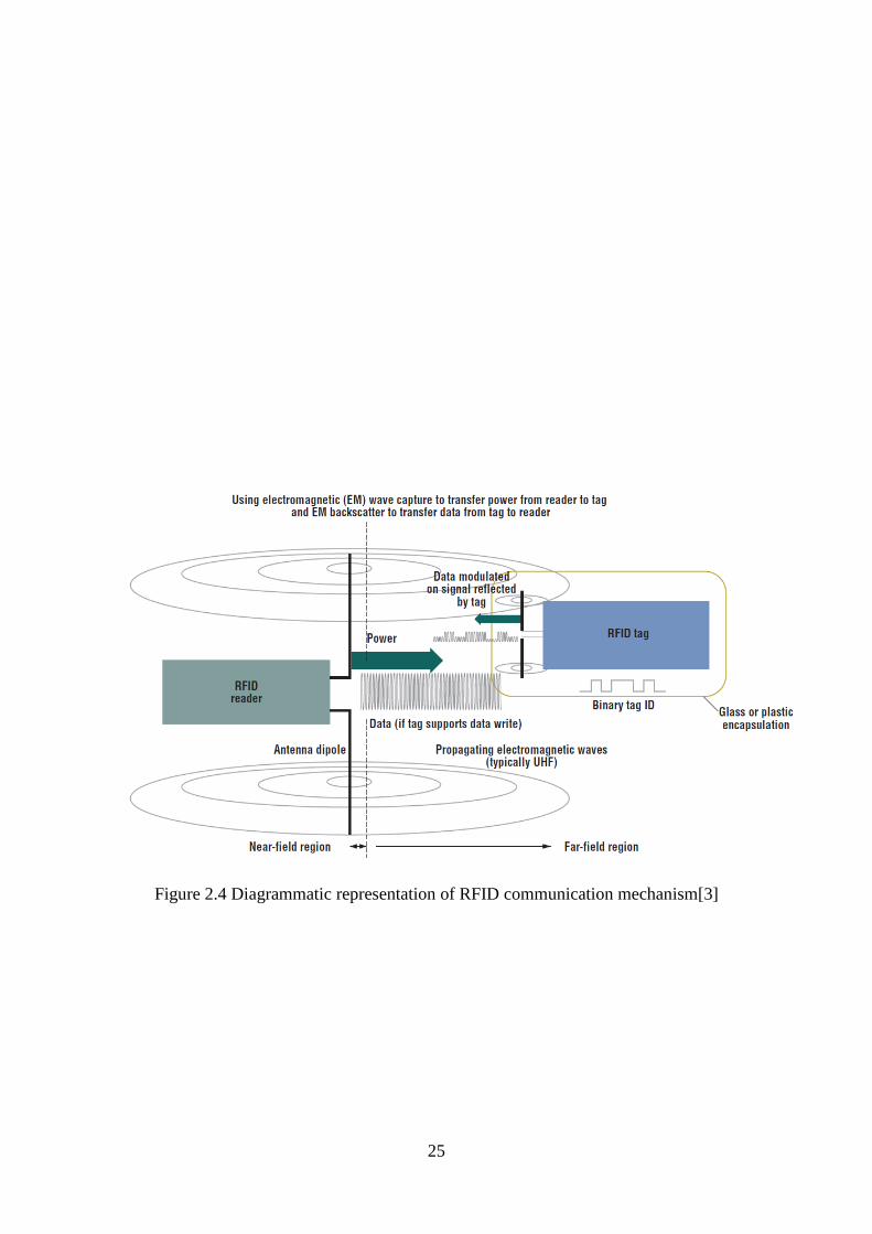
2.4.1. Radio Frequency Identification
Radio Frequency Identification is a technology that uses radio waves to facilitate
communication between a tag and a receiver. The tag is used to store information that can be
read by the reader upon interaction within a range limited to a few meters [46]. The tag is
comprised of a microchip which stores programmed information and an antenna to interact
with the reader. The reader is a transceiver which interrogates a reader that is in range in order
for it to read the information on it.
25
Figure 2.4 Diagrammatic representation of RFID communication mechanism[3]
26
RFID devices can be broadly classified into two categories:
Passive tags are simplistic and cheap with no built in power supply. They use the
electromagnetic field from the reader’s interrogation signal as a power source for the inbuilt
circuitry and backscattering to transmit the stored information back to the reader [4]. There are
variations of this implementation which contain inbuilt power sources and no transmitter
referred to as semi-passive device [4].
Active tags have an integrated power source and a transmitter. These are self-reliant in
powering the internal circuitry and transmitting a signal to the reader. The other main difference
is that it transmits a continuous signal whilst passive RFID does not.
RFID technology is used in various applications such as supply chain for inventory tracking
and as a security measure against counterfeiting. It also improves stock management
capabilities of a company when implemented. RFIDs, with the augmentation of proprietary
encryption, have been implemented as a form of access control with tags embedded in
employee cards or student cards and used to restrict access to secure buildings or offices [4].
Telepass or Autopass devices also utilize RFID so that payments at toll gates can be processed
automatically without the need for the driver to interact with the toll gate or the toll gate
operator. Of all the uses of this technology, the one of interest in this study is the use in
automotive security where RFID tags are embedded in the vehicle key as a form of an antitheft
measure and to restrict duplication of the key. Some more secure alternatives to the standard
RFIDs called digital signal transponders (DSTs) are used in vehicle immobilizers to
continuously interrogate the vehicle key, a deterrent to cutting off the fuel injectors[47].
Most of the current keyless entry systems use RFID technology together with other
technologies like Bluetooth and cellular networks to interact with the vehicle and manipulate
its functions as covered in the above subsection.
Although most implementations of RFID technology are augmented with some variation of
cryptography to ensure security, devices are still susceptible to a range of attacks that can
compromise the confidentiality of the devices and result in breaches. Bono et al. [47] conducted
a security analysis on RFID devices with cryptographic functions implemented on them and
managed to successfully breach the security of such a device through reverse engineering,
cracking the encryption key and spoofing the device. This was accomplished through obtaining
a schematic related to the cipher used in the encryption and observing the responses of the

27
device to their actions which enabled them to successfully recreate the cipher and its
parameters.
A study[48] investigated the breaching of RFID hardware cryptographically protected with a
cipher unknown to the authors through various techniques in order to obtain the keys used by
the cipher. This again serves to highlight the limitations of RFID technology regardless of the
security technology used to secure it. There is no doubting the uses of this technology but the
fact is with the rapid advancements in all facets of technology, it has become less strenuous to
compromise the security used on RFID technology which lacked the adequate technical
specifications to implement any strong cryptographic functions to begin with [49].
RFIDs, as discussed by Peris-Lopez et al. [10], are susceptible to physical attack through
hardware tampering, denial of service through signal jamming, counterfeiting and spoofing,
eavesdropping through interception of transmitted information and analysis of the traffic due
to the lack of security surrounding the technology and the way in which it operates. This poses
a great concern for the vehicle manufacturers who implement this technology as part of their
security infrastructure. Although some implementations of RFID involve the use of
cryptographic key pairs [47] to combat cloning and replay attacks, it does not provide adequate
protection against traffic interception and even when the traffic is encrypted a skilled adversary
with enough time will decipher the transmission.
Continuing with the theme of functional and security concerns surrounding RFIDs, Juels [50]
mentioned how there are concerns of object tracking device reconnaissance since RFID devices
continuously transmit (Semi-active or active tags) or respond to interrogation signals by readers
(passive tags) without interaction or notification of the user. This leaves the user unaware to
any attacks being carried out on them or their hardware. This can lead to attacker devices
probing victim devices without any countermeasures to prevent the interaction thereby
increasing the chances of the victim’s device being compromised. A solution was proposed in
[51] where an RFID device was to use a cap to limit the number of times a reader could
interrogate it and limit the amount of data transmitted to and from the RFID device. This was
all in an effort to reduce the chances of data being compromised through continuous
interrogation by an attacker’s RFID reader. In [52] they manipulated the distance between the
RFID tag and reader in a way which prevented the interception of confidential information by
attackers through the use of a random string and a logical XOR function to obfuscate the
sensitive data.

28
A survey by Peris-Lopez et al. [10] attempted to address the concerns of RFID through
consolidating numerous sources that tackled different vulnerabilities using varied methods like
the proposal in [53] to create a kill switch that could permanently deactivate the RFID tag but
such a solution is borderline drastic and would only be suitable as a last resort. Cryptographic
approaches were also considered by [54] who suggested the use of rewritable memory to store
a randomly generated identification for the tag that it would use to conceal the true tag identity
as a security measure to combat tracking, whilst Feldhofer et al. [55] opted for a symmetric
key encryption solution based on an encryption implementation found in [56]. Another
approach implemented was the use of hash functions as seen in [52] but the limitations of this
approach stem from the use of additional infrastructure to facilitate full functionality of the
RFID device thereby making the solution more complex to implement. In addition, the function
would be one way so it lacks a feedback mechanism that can be used for validations.
On a tangent, RFID technology still has its uses in modern day vehicle systems that do not
require security functions like the vehicle tracking system suggested by Pandit et al. [57] that
aims to address the issues of congestions and vehicle theft. In [58] a similar implementation to
the one mentioned above was proposed, which used ultra-high frequency (UHF) RFID devices
to log vehicle statistics in certain areas which contained reader hardware and a monitoring
system. Lee et al., [59] proposed the use of RFID devices to augment inter-vehicle
communication facilitated by VANETs as part of a more accurate global positioning system.
29
2.4.2 Bluetooth
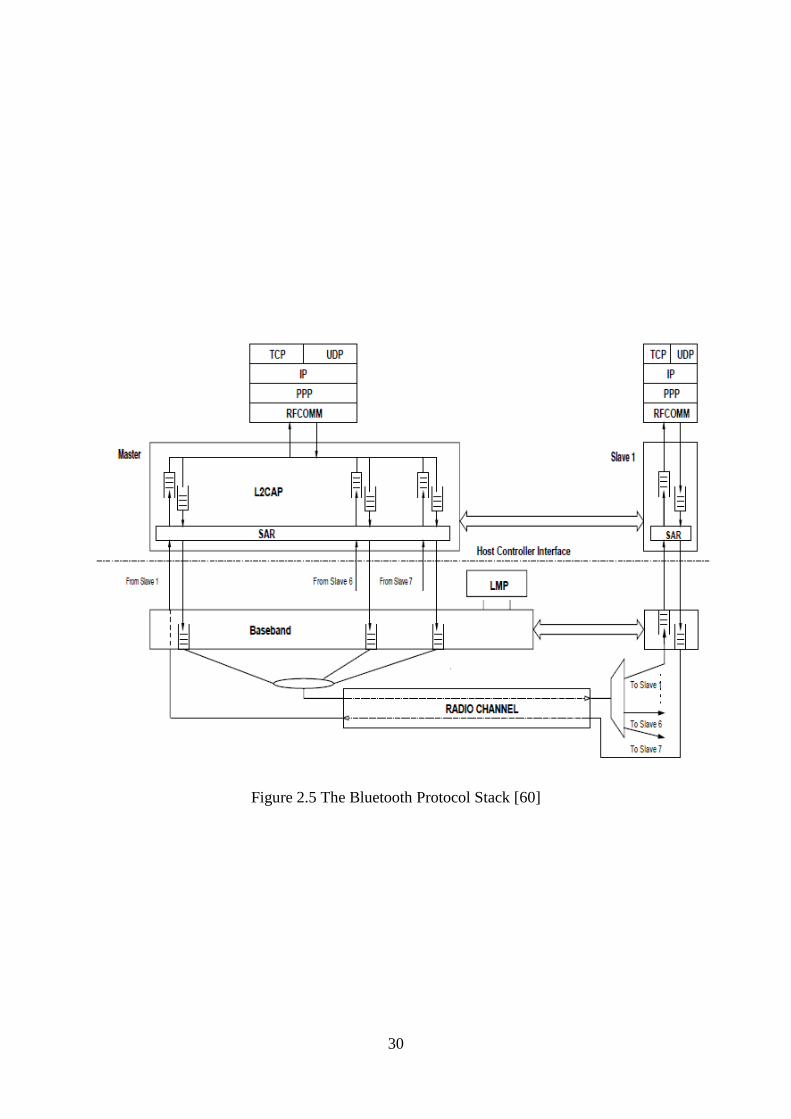
Bluetooth wireless technology is a master driven time division duplex system that transmits
data and voice over asynchronous and synchronous channels respectively [60] thereby
facilitating short range communication between two wireless devices as shown in Figure 2.7
and it is designed by a company called Bluetooth SIG Inc. It effectively eliminated the need to
connect different devices through physical cables and adapters by providing a low cost
universal communication interface that could be implemented in devices with varying
architectures thereby enabling them to communicate seamlessly [61]. This technology uses low
energy hardware to communicate and transmit data on the 2.4 GHz spectrum.
30
Figure 2.5 The Bluetooth Protocol Stack [60]

31
Due to the rise in smart appliances and an increased focus on interconnectivity of real world
devices used daily by people, there has been developments in implementing numerous wireless
devices and services in everyday utilities to increase functionality. A particular example would
be the inclusion of Bluetooth devices in infotainment systems of almost all vehicles [62] that
are currently in production for media consumption or more advanced features such as
controlling vehicle systems. Talty, et al. [63] proposed the use of near field communications
to securely pair a Bluetooth device belonging to a user with one found in the vehicle so that the
two devices can communicate and transmit data between them. This could be useful for features
such as mobile phone music playback via the infotainment system. In another publication,
Talty, et al. [64] proposed the use of Bluetooth technology to connect to the vehicle and to
transmit diagnostic information from the vehicle to the connected device thereby eliminating
the need for a proprietary interface or specialised hardware. This allows for automated
communication between the vehicle and the use device without intervention on the part of the
user.
Chen, et al., [65] discussed the use of an on board vehicle antitheft system that has a Bluetooth
module integrated into it for communication with a user device that is used to authenticate the
user and unlock vehicle functionality. When the on board Bluetooth module does not receive a
signal from the Bluetooth module on the user device, it arms the vehicle security and only
disables it after receiving a signal from the user device when it is in range. While the proposed
system is more secure, the previously mentioned RFID, is still susceptible to man-in-the-
middle attacks and cloning from adversaries with enough technical skill. It also does not
address the other problem with RFID of continuously transmitting a signal thereby running the
risk of eavesdropping from rogue Bluetooth devices belonging to the attackers.
2.6. Vehicular Ad hoc Networks
VANETS are a sub category of Mobile Ad hoc Networks[6] which facilitate the
communication between vehicles as network nodes taking into account the mobility of the
vehicles in the communication practices used for data transmission. They fall under the
mandate of Intelligent Transport Systems (ITS)[66] and have found several uses from safety to
entertainment applications in vehicles. They enable vehicles to provide active safety which
prioritises the delivery of timely safety information to the user from other nodes or vehicles in
the form of warning messages. Vehicles communicate with each other through On-Board Units
(OBUs) in what is referred to as Vehicle to Infrastructure Communication (V2I) and to roadside
infrastructure called Road Side Units (RSUs) in what is referred to as Vehicle to Vehicle

32
Communication (V2V)[67] to relay or obtain information. The main advantage of VANETs
lies in their inherent ability to self-organise without the use of a central controller to coordinate
communication and issue commands, making them highly versatile and highly configurable.
They operate on the 75 MHz of Dedicated Short Range Communications (DSRC) spectrum
allocated to them at 5.9 GHz.[68].
Al-kahtani [69] conducted a survey which detailed the vulnerabilities of VANETs including
but not limited to:
Denial of Service (DOS) - involves the transmission of fake messages to nodes to
hamper network functions through processing of unnecessary transactions.
Timing attacks – purposefully creating a delay in the transmission of messages from
one node to the other resulting window of validity of the data especially in urgent
scenarios.
Malware – the use of malicious software in transmission between nodes to
compromise the security and functionality of On-Board Units in vehicles or Road Side
Units.
Masquerade – an attack where a malicious actor uses the legit identity of another node
to communicate with a target consequently obtain otherwise private information.
Sybil Attack[70, 71] – an attacker appears as multiple nodes by generating multiple
illegitimate identities thereby tricking other legitimate nodes in the network into
perceiving a wrong size of the network.
While VANETs offer a certain level of in-built security measures to counteract most of the
conventional attacks, it is worth noting that there are attacks for which they cannot defend
against due to the complexity of the attacks and the limitations imposed on VANETs from a
design perspective.
2.7. Normal Networks (Wi-Fi Direct)
Wi-Fi refers to a wireless communication technology where compatible devices use time-
division duplex [72] to transmit data between themselves without the constraints of a physical
connection. This technology is governed by the IEEE 802.11 standards [73] and operates
commonly on the 2.4 GHz and 5 GHz frequency spectrums. This technology is of particular
interest because it is a possible vector for facilitating communication between devices without
the need for a physical connection and it also provides protection mechanisms in the form of
encrypted exchanges to secure device to device communication. Given the wide scope in which
33
Wi-Fi functions, the device to device communication features will make a good foundation for
a robust secure key to car closed network system that will be crucial for the sake of this study.
Wi-Fi Direct [74] is an expansion upon the 802.11 standard [75] which allows devices with the
adequate hardware to connect to each other and exchange data wirelessly without the use of an
access point or central controller [76]. The devices in question go through a process of
discovery where they detect other devices in the same channels and after receiving a response,
negotiation of group ownership commences where one of the devices is selected to be the group
owner (GO)[77] on the basis of the highest intent value. This process is completed through the
comparison of attributes such as the device information, intent value and operational channel.
After negotiations and selection of the GO, security is set up and the other devices within the
network are assigned IP addresses through the dynamic host configuration protocol (DHCP) in
order for them to start communication. When the device setup is complete, communication and
transmission can begin in a secure environment. Due to how Wi-Fi Direct originates from
802.11, it inherits numerous properties from it as well such as energy saving, security and the
ability to implement more functional device to device communication than any other
counterparts. Wi-Fi Direct is meant to connect multiple devices as group members (GMs) and
legacy clients (LC) to the GO after the GO sends out beacon packets to devices within range
and they respond thereby joining the network.
As is the case with other technologies, Wi-Fi Direct also faces security challenges. A study by
Shen et al. [78] details the numerous ways in which attackers can compromise the security and
functionality of these networks; detailing the use of eavesdropping on open channels
commonly used in wireless communications to capture traffic, impersonation of a legitimate
user through the spoofing of their medium access control (MAC) address and IP address and
message modification which involves the attacker altering data transmissions without being
detected. The exchange of secret keys in Wi-Fi Direct are conducted using the Diffie-Hellman
key agreement [79] which utilizes unprotected and open networks to exchange data between
nodes that are used to calculate the shared secret key to be used in the transmissions between
the two devices. This key exchange is vulnerable to numerous attacks as detailed in [80] by
Kocha et al. who investigated the use of timing attacks on numerous key exchange mechanisms
including but not limited to Diffie-Hellman. Shen et al.,[78] also elaborated on how the
traditional Diffie-Hellman key exchange was susceptible to man in the middle attacks (MITM)
from an adversary who was technologically savvy enough to intercept the publicly shared

34
information between the two nodes and send his own publicly shared information to each of
the nodes to complete the generation of shared secret keys with both devices.
Most of these vulnerabilities have been eliminated through the enhancement of traditional
security mechanisms with elliptical curve cryptography [81] making it inefficient for
adversaries to attempt deciphering or breaking the security mechanisms when they are
deployed. The National Security Agency (NSA) published a set of standards referred to as NSA
Suite B[82] used as guidelines on the level of security required for devices used in the United
States government for secure communication. This set of requirements covers all aspects of
network communication from key exchange to bulk data transmission and uses very robust
security protocols to ensure that it is close to impossible for an adversary to compromise
secured systems and secured transmissions between the systems.
The standards contain specifications for two different levels of security, namely SECRET and
TOP SECRET but for the sake of this study the focus will be on the SECRET standards only
as they should prove adequate to secure the proposed system and computationally less straining
when compared to the latter. For the encryption, the preference is towards AES-128[83] or
higher using Galois/Counter Mode[84] due to its complexity and the block size. It makes it
computationally expensive to break even with highly powerful hardware. The digital signature
required is an Elliptical Curve Digital Signature Agreement with a prime modulus which is at
least 256 bits in length [85]. The key agreement between devices is done through the use of
Elliptical Curve Diffie-Hellman (ECDH) or Elliptical Curve Menezes-Qu-Vanstone (ECMQV)
authentication protocols with a minimum key length of 256 bits with the use of a prime
modulus. Hash functions to ensure data integrity is conducted through the use of Secure Hash
Algorithms (SHA-256) and higher.
The above mentioned suite of cryptographic protocols ensure secure transmission of data
between nodes and in the event of eavesdropping by an adversary, the data is not compromised
due to the multiple measures taken to ensure security. Gura et al.,[86] investigated the use of
elliptical curve cryptography on an Amtel ATmega128 which is a processor with a clock speed
of 8 MHz in an effort to mitigate risks that came with data transmissions from small devices
connected to the internet and determined the cryptographic operations required to be
computationally inexpensive on the provided hardware and therefore possible despite the
hardware limitations which eliminated the possibility of flexible key management. With the
advances in microprocessor technology, System on Chips like the Qualcomm Snapdragon

35
845[87] can perform the cryptographic functions at a much higher rate, using less energy and
at higher clock frequencies and efficiency due to specialised hardware integrated into the chip
to process cryptographic functions.
2.8. Network Infrastructure Selection – Normal networks vs. VANETS
The unescapable fact is that VANETs are specialised for large scale deployment [88] in
scenarios where the communication in question is between multiple vehicles as indicated by
the way in which they operate and their accounting for high mobility in selection of components
like the routing protocols used to transmit information from one node to another. With the
vehicle security in question, there are only two nodes communicating, one being the key and
the other being the car and the communication is exclusive thereby eliminating the need for
numerous routing protocols and a large scale deployment solution. Due to the fact that the key
is within the vehicle at all times of operation, the high mobility factor catered for by VANETs
is eliminated since devices are constantly within range of each other. A traditional network
based solution network is ideal due to the plethora of features that it can offer in the securing
of both communication devices from the deployment of highly secure cipher suites to the use
of mechanisms such as one-time passwords (OTPs) and virtual private networks to prevent
replay or man-in-the middle attacks. With this in mind, it stands to reason that the main
technology would utilize traditional network infrastructure and the vehicle would use VANETs
to transmit black box data to a RSU which will in turn transmit the information over the internet
to a secure manufacturer server for storage and analysis.
2.9. One Time Passwords
One Time Passwords are an authentication system used as a contingency in most cases to verify
the identity of the authenticated user. They work through the use of server side and client side
software whereby the server side software sends a pseudorandom token to in the client side
software that can be used together with the password to log a user[18]. Such a token expires
after a single use and therefore cannot be reused in a later session making it useless in a replay
attack where the attacker captures traffic between the authenticating devices for reuse. For a
one time password to be validated, the server and the client devices must share a secret key and
set of cryptographic functions that can be used to calculate the unique password. The server
generates a session specific challenge that is then sent to the client device after being encrypted
by the shared secret key. The client receives the encrypted information and decrypts it to obtain
the session challenge which runs a predefined set of cryptographic functions on it to generate
36
a onetime password which it then encrypts and sends back as the response to the server. Upon
reception, the server decrypts the response and calculates its own pass word based on the
session challenge previously transmitted and then compares it to the response from the client.
If there is a match, authentication is successful and the client is logged in otherwise the login
fails.
The effectiveness of the onetime password system is based on the secure hash algorithm (SHA)
and its properties of non-invertability [89] which in this case will produce an output with a
minimum key length of 256 bits. The client device runs the challenge through N number of
SHA sequences before subtracting N to (N – 1). The server goes through the same process with
the challenge and compares the two passwords for authentication, a variation of Lamport et
al.[17]. N is an arbitrary value used to determine the number of cryptographic operations and
is synchronised between the client and server devices for functionality. The server can test a
limited range of N in the case of an initial mismatch before invalidating the authentication
attempt [12]. The use of randomly generated secret shared keys between the server and the
client facilitates a more stringent approach in the implementation of onetime passwords making
old secret keys invalid and further securing the system. In [90] a hash-based message
authentication code (HMAC) based onetime password system was proposed where the counter
actually increments and a resynchronisation protocol is used when there is a mismatch in the
passwords produced by the two components of the system. It also discussed the possible
weakness that arises from truncating the SHA output in the interest of efficiency as it opens the
system to brute force attacks.
While the level of security offered by onetime passwords is not as robust as that of public key
cryptography, it is sufficient for setups where there is no communication with a third party
certificate validation infrastructure. With that being said, there is a need to enforce prerequisites
which make the system sufficiently robust and usable in a real life scenario without sensitive
data being compromised. Haller et al. [13] suggested a onetime password system which uses a
64 bit input and a non-secret seed both of which are potential attack vectors from a security
perspective as an adversary can perform a brute force attack on 64 bits and the non-secret seed
aids a reverse engineer in their efforts to defeat the system. In [91], Huang et al. suggested a
onetime password system that uses instant messaging (IM) and a web based infrastructure to
provide a user a password on their IM client during each login attempt. This approach uses the
pre-existing security mechanisms built into the internet such as Transport Layer Security (TLS)
to encrypt traffic but its main drawback is that it cannot be implemented in an isolated

37
environment where the use of an IM client is not required, thus limiting the scope of its
functionality. Additionally, if an adversary manages to compromise any aspect of the
underlying infrastructure it is built upon, the system may be compromised as well.
2.10. Biometric Authentication
Biometric authentication is the use of unique bodily physical structures to uniquely identify an
individual and verify their identity. As detailed by Liu et al. [92], biometric information
encompasses facial features, hand geometry, iris and fingerprint to name a few. It is an
alternative form of authorization offering more security and eliminating the need to memorise
or carry hardware based credentials. Its only shortcomings are in the form of the inability to
replace them in the event of stolen identity data and its non-secrecy due to the fact that
fingerprints are openly visible [93]. For the scope of this study, the focus is on fingerprint
verification as it has been proven to be one of the most reliable forms of biometric
authentication [94] and offers ease of use with a non-invasive scanning procedure. Faundez-
Zanuy [93] detailed the different implementations of fingerprint identification technology
ranging from optical scanners that use light to record the pattern to capacitive scanners, clearly
showing the benefits and shortfalls of each technology. The capacitive scanners are the most
commonly implemented currently due to the small size and ease of integration into mobile
systems.
Fingerprints are identified though ridges and valleys found on and unique to each finger called
minutiae through numerous algorithms, some of which are detailed in the works of Multoni et
al. [95]. To briefly describe the collection of minutiae, an image of the fingerprint is used where
the image is oriented taking into account the gradients along the pixels in both horizontal and
vertical axes. The area of interest is isolated and refined for clear pattern identification, after
which minutiae points are clearly identified and stored, together with the orientation and
segment of each point [96].
There are many concerns surrounding the security of biometric systems with Roberts et al. [97]
detailing the numerous potential attack vectors found on biometric systems which could enable
an attacker to conduct identity spoofing. However, with the colossal advances of the fingerprint
recognition technology, all the previous concerns have been addressed. Companies like
Infineon VeriTouch [98] and Qualcomm [99] have invested millions into advancing the
technology through the use of encrypted vaults such as the one detailed in [100] and the use of
dedicated processing units such as the secure processing unit (SPU) offered as a component of

38
Qualcomm’s Snapdragon 845 mobile processor (SoC)[87] used in mobile devices which
isolates the biometric functions on the chip eliminating the need to transmit the secure pattern
data for verification. Such advancements in the technology makes it ideal for wide scale
deployment in mobile devices as a secure authentication mechanism [98].
2.11 Critical Literature Review
The various works explored in this chapter cover the various attempts made across the globe
by different individuals and organisations in an attempt to improve the security in different
types of vehicles. The common trait seems to be the specialisation in a certain problem thereby
leaving some pre-existing avenues of compromise still open. It is refreshing to observe cases
such as that of Tesla in which their current implementation of security technology leaves little
to be desired and is close to what can be considered ideal. On to the technologies themselves,
it is apparent that the approach of using a single technology is less fruitful than that of using
multiple elements, the only stipulation being the different elements function uniformly and in
unison. Another point to note is that some existing weaknesses in current security technology
are being phased out by the rapid development of technology as a whole, which is resulting in
either the strengthening of current technologies using new techniques or the development of
completely new technologies that address the weaknesses with relative ease.
The solution proposed in this thesis leverages the rapid advancement in processor architecture
where mobile processors used in smartphones are powerful enough to run full desktop
computers and their sizes enable them to be embedded in something as small as a car key. This
is similar to the use of RFID tags in keys as an antitheft mechanism to combat the use of
counterfeit keys but with exponentially more complex functions occurring between the vehicle
and the key other than a simple check. Ultimately from the literature studied above in earlier
subsections, it is a fair assessment to state that some of the compromises in the existing
technologies are due to the age of the technology and the approach taken in applying it in
vehicle security. This accounts for most of the cases with the exception of newer
implementations in which the improvements were improperly implemented and as a result,
new attack vectors were created.
2.12 Chapter Summary
This chapter contained a detailed literature review of the current existing technologies used in
the security implementations in modern vehicles. It also contained substantial literature on
different technologies that can be used to replace and improve upon current security and the
chapter also looked at more sophisticated alternatives to user authentication besides a simple
key that could be used to enhance the security offered by vehicle systems. Finally a look into
networking and network technologies as an alternative approach to tackling vehicle security
was considered through the investigation of different types of networks.

39
CHAPTER 3
RESEARCH METHODOLOGY AND MATERIALS
3.1 Chapter Outline
This chapter details the research methodology and methods used in this work together with the
nature and functionality of the proposed system, detailing all of its functions and the extent to
which it functions. It covers the system’s requirements, the system design and expected
performance.
3.2 Methodology and Design
This section of the chapter discusses the research methodology used to obtain the information
relevant for completion of the goals set out in the earlier chapters. This includes formulation
of the methodology by which the assessment was conducted and defining parameters for data
to be collected and analysed.
The Figure 3.1 below details the sequence in which the research was conducted and supports
the process descriptions that follow:
The research concept was developed through investigation and a preliminary
literature review to justify the validity of the research work. The research proposal
was subsequently developed with objectives and area of interest defined.
A comprehensive primary literature review was conducted investigating multiple
factors around the research area including but not limited to, existing vehicle
security, literature on vehicle theft, exploration into new and improved security
approaches and the weaknesses that are found in such approaches.
This aided in the conceptualisation of a security system that addressed most of the
discovered weaknesses and formulation of a sequence of tests to be conducted on
the simulation equivalent components of the actual proposed security system.
Simulations were conducted using predefined parameters and results were gathered.
Qualitative and Quantitative methods of analysis were used on the results.
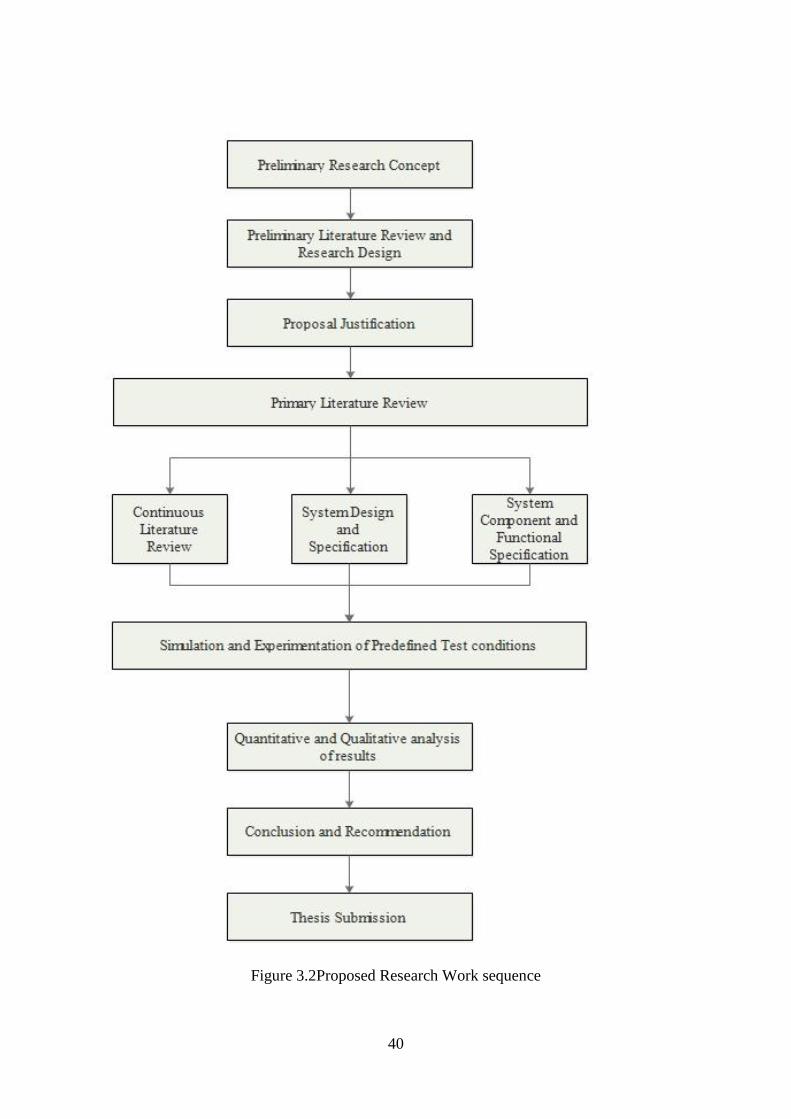
40
Figure 3.2Proposed Research Work sequence
41
In order to obtain valid and reliable results for this study, the Simulation research method was
used to model varied situations in which the same data of interest were obtained and analysed.
The data obtained after manipulating the simulation devices has two facets of analysis and
therefore a mixed approach was used in the analysis of the resulting data in order to achieve
the intended primary goals.
Simulation method of research is used in instances where the study falls out of the bounds of
the experimental realm, meaning that it is not possible to actually implement the system in
question in real life at that particular moment due to financial or technological constraints,
which happens to be the case in this study.
The mixed method of analysis [101] involves the use of both quantitative analysis [102] in the
form of numerical analysis where the numerical results are compared to a control set in order
to derive a conclusion and qualitative [103] analysis in which non-numerical data is visually
analysed in order to derive an analysis to obtain information from the results obtained in the
simulation. These methods are used in parallel to obtain more comprehensive results based on
statistical and observational data. The statistical data would be the quantifiable parameters of
interest such as performance in a wireless network whilst the observational data would be the
visual comparison between the results of a simulation to note the differences and similarities
in them. The entire simulation is done in a lab environment as there was no need to involve the
human factor beyond the intended functions of the simulation. Additionally, the possible
interview of other individuals working in similar security technology solutions was infeasible
due to the fact that most of the information is proprietary and therefore not freely available or
accessible in a dialogue.
3.3 Methods and Techniques
This section of the chapter describes the system design, components and architecture. It
provides information on the way in which the system functions including the hardware
components required in every sub-module and their functional parameters.
3.3.1 System Overview
The system being designed aims to increase vehicle security by eliminating the vulnerabilities
of the security systems currently in use in most vehicles. The system aims to accomplish this
feat by using technologies such as capacitive fingerprint scanners, System on Chips (SoCs) and
wireless interfaces to control security functions. These functions include the secure
communication of the wireless key and the car with mechanisms put in place to prevent man-

42
in-the-middle attacks or replay attacks and any other techniques that can be used by
perpetrators to compromise the security of the vehicle.
The functions also extend to anti-hijacking where the vehicle will require biometric
authentication to unlock the key and car functions. This system benefits the user by providing
more secure vehicle security and anti-hijacking measures which cannot be bypassed as easily.
It also ensures that in the event that the key is stolen from the owner, the car cannot be unlocked
or started since biometric authentication is a prerequisite to unlocking system functions.
3.3.2 System Analysis
System analysis involves the in-depth investigation of aspects of a system that is being
designed. That includes an in depth look at the problem that has to be solved and the methods
in which the problem can be addressed in the most efficient manner. In the case of the current
system, the system analysis process is used to detail the functions of the components in the
system and the different technologies that are included in the build of the system. It is also used
to outline the way in which system components interact with each other in handling required
functions.
a) System Requirements Process
There are various articles in the scientific and security communities that detail the
vulnerabilities and shortcomings of conventional vehicle security as well as videos made by
security researchers that illustrate ways in which these on-board systems can be compromised
by an individual with the right knowledge and hardware. This coupled with the alarming rate
of car theft, shows a need for a different approach to vehicle security that accommodates the
possibility of a security system without any of the current systems’ vulnerabilities. This system
would aim to provide functional improvements as well as non-functional additions to bolster
its protection against physical contact and tampering.
This system’s requirements are a result of a brainstorming on alternative security protocols that
bare robust (options) and can be deployed in the vehicle security environment with currently
existing technology. The requirements process is also guided by a set of use cases which are
considered to be the main functions of the system. Requirements are crucial as they serve as a
guide to determining the functions and limitations of the system as well as the components
needed for the system to operate optimally and achieve its intended goal.
43
b) System Requirements Specification
System requirements specification refers to the detailed description of how components in the
system interact and how the user interacts with the system as a whole. It outlines the behaviour
of the system and that includes the specific capabilities of the system and its limitations. The
requirements are divided into functional and non-functional. Functional requirements are
technical details outlining the fundamental operations of the system, that is, the system’s
response to different user interactions. Non-functional requirements refers to the state of the
system in its functions from a non-technical perspective that does not affect the underlying
functional components of the system [104].
The system requirements specification fall under three entries or components of the
system, the KEY, the CARSEC and the BLACKBOX, all as functional components
that make up the proposed system and function in a co-dependent manner.
The KEY refers to the system embedded in the physical key of the vehicle and is used
to gain entry and access vehicle functions.
The CARSEC refers to the security system embedded into the car that is used to secure
the car against theft and hijacking.
The BLACKBOX refers to the securely stored diagnostics box in the vehicle that
collects information during the operation of the vehicle and transmits the information
to a secure server when certain predetermined conditions are met.
Based on the above mentioned components, the functional requirements (FR) and non-
functional requirements (NFR) that will be satisfied by our system are presented in Table 3.1,
3.2 and 3.3 respectively.
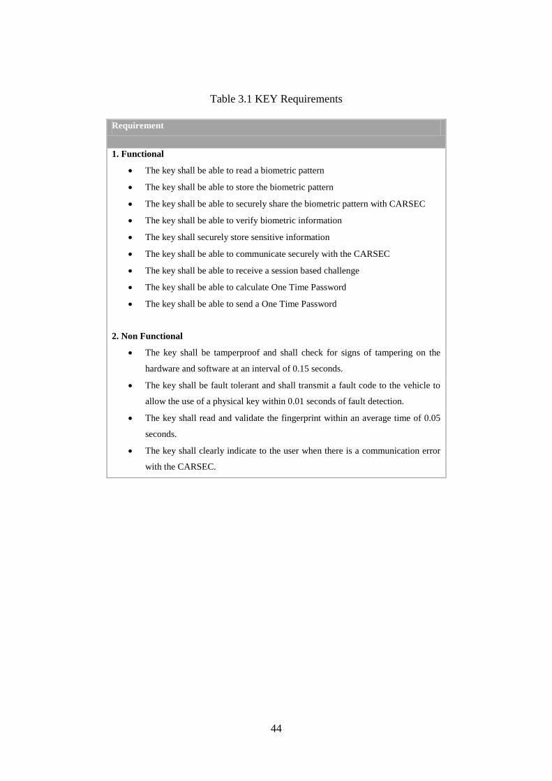
44
Table 3.1 KEY Requirements
Requirement
1. Functional
The key shall be able to read a biometric pattern
The key shall be able to store the biometric pattern
The key shall be able to securely share the biometric pattern with CARSEC
The key shall be able to verify biometric information
The key shall securely store sensitive information
The key shall be able to communicate securely with the CARSEC
The key shall be able to receive a session based challenge
The key shall be able to calculate One Time Password
The key shall be able to send a One Time Password
2. Non Functional
The key shall be tamperproof and shall check for signs of tampering on the
hardware and software at an interval of 0.15 seconds.
The key shall be fault tolerant and shall transmit a fault code to the vehicle to
allow the use of a physical key within 0.01 seconds of fault detection.
The key shall read and validate the fingerprint within an average time of 0.05
seconds.
The key shall clearly indicate to the user when there is a communication error
with the CARSEC.
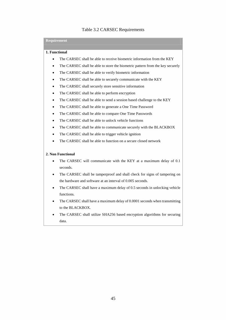
45
Table 3.2 CARSEC Requirements
Requirement
1. Functional
The CARSEC shall be able to receive biometric information from the KEY
The CARSEC shall be able to store the biometric pattern from the key securely
The CARSEC shall be able to verify biometric information
The CARSEC shall be able to securely communicate with the KEY
The CARSEC shall securely store sensitive information
The CARSEC shall be able to perform encryption
The CARSEC shall be able to send a session based challenge to the KEY
The CARSEC shall be able to generate a One Time Password
The CARSEC shall be able to compare One Time Passwords
The CARSEC shall be able to unlock vehicle functions
The CARSEC shall be able to communicate securely with the BLACKBOX
The CARSEC shall be able to trigger vehicle ignition
The CARSEC shall be able to function on a secure closed network
2. Non Functional
The CARSEC will communicate with the KEY at a maximum delay of 0.1
seconds.
The CARSEC shall be tamperproof and shall check for signs of tampering on
the hardware and software at an interval of 0.005 seconds.
The CARSEC shall have a maximum delay of 0.5 seconds in unlocking vehicle
functions.
The CARSEC shall have a maximum delay of 0.0001 seconds when transmitting
to the BLACKBOX.
The CARSEC shall utilize SHA256 based encryption algorithms for securing
data.
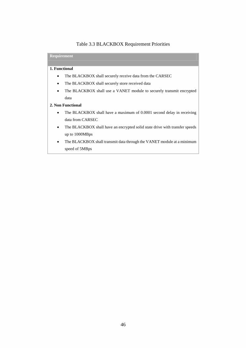
46
Table 3.3 BLACKBOX Requirement Priorities
Requirement
1. Functional
The BLACKBOX shall securely receive data from the CARSEC
The BLACKBOX shall securely store received data
The BLACKBOX shall use a VANET module to securely transmit encrypted
data
2. Non Functional
The BLACKBOX shall have a maximum of 0.0001 second delay in receiving
data from CARSEC
The BLACKBOX shall have an encrypted solid state drive with transfer speeds
up to 1000MBps
The BLACKBOX shall transmit data through the VANET module at a minimum
speed of 5MBps
47
3.3.3 System Modelling
System modelling refers to the conceptualization of a system in a graphical or functional
manner, in order to illustrate the way in which the system will function and the components
that were used in the system. It serves to provide more information on the nature of the system
in the form of the system’s structure, functions and other details that will further detail the
system[105].
For this study, system modelling is an important step as it helps to conceptualize a virtually
non-existent solution to the problem being addressed and as such, system modelling helps to
provide much needed information on the specifications of the system under design. With the
usage of use cases, actors, roles and other models, we are able to show the different components
of the system and how they interact with each other throughout their various roles and this also
helps to expose the limitations of the proposed system, if any, and to remedy them.
3.3.4 Use Case Model
Use cases are abstract representations of scenarios that may occur that affect the system and
how they detail the manner in which the system will behave in such scenarios. They help to
define the scope of the system’s functionality and that is what makes them crucial in this
particular study. The collection of use cases in this study is used to detail all possible
interactions of components within the system and of the system with external factors.
The system as a whole can be divided into the vehicle (CARSEC), the key (KEY) and the Black
box (BLACKBOX) where these components can be referred to as the actors in the system
performing different roles in unison with the other components, thereby making the system
function.
a) Actors
Actors are components of the system that may be part of the system or external that interact
with the system. In this research, the actors vary from the user (human) that interacts with the
system to the components within the system that interact with each other inorder to make the
system functional. Actors’interactions with or within the system are detailed through use cases.

48
Figure 3.2 System actors

49
b) Actor Roles
Roles represent the different responsibilities of the actors in the system. They detail the
interactions between the actors and the system and help to illuminate on the relationship
between the actors and the system.
Table 3.4 Actors and Roles
CARSEC KEY BLACKBOX
Securely synchronize biometric
information from the KEY,
Transmit interrogation signal,
Receive response from the KEY,
Send session specific challenge,
Generate One Time Password,
Compare and validate One Time
Password,
Unlock vehicle functions,
Trigger ignition,
Send log data to BLACKBOX,
Send feedback to the KEY,
Detect tampering,
Troubleshoot
Record fingerprint from user,
Securely store fingerprint, Securely
send biometric information to the
CARSEC,
Read and authenticate fingerprint,
Detect tampering,
Securely transmit information to
CARSEC,
Respond to CARSEC node
interrogation signal,
Receive session specific challenge,
Generate One Time Password,
Securely send One Time Password,
Get feedback from CARSEC,
Troubleshoot
Receive secure log data from
CARSEC,
Check for tampering,
Transmit log data to RSU securely

50
c) Use Cases
This suubsection presents the system use case diagram showing the actors, use cases and
possible interactions on the system. This is shown in Figure 3.3.

51
Figure 3.3 VANET Antitheft system use case diagram

52
d) Use Case Description
This section presents Tables 3.5 to 3.12 which provide the description of each use case shown
in Figure 3.3.
Table 3.5 below details the manner in which the security system in the vehicle (CARSEC)
detects the keyfob (KEY) and sends a session specific challenge that is used to generate an
OTP.
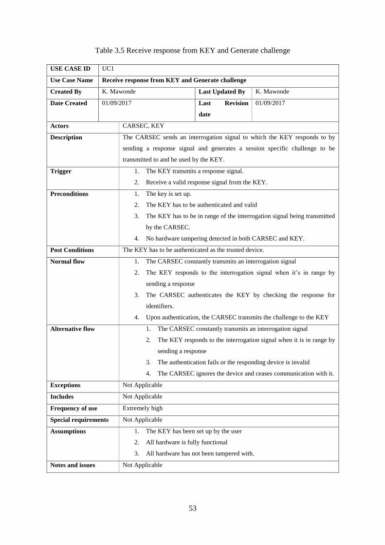
53
Table 3.5 Receive response from KEY and Generate challenge
USE CASE ID UC1
Use Case Name Receive response from KEY and Generate challenge
Created By K. Mawonde Last Updated By K. Mawonde
Date Created 01/09/2017 Last Revision
date
01/09/2017
Actors CARSEC, KEY
Description The CARSEC sends an interrogation signal to which the KEY responds to by
sending a response signal and generates a session specific challenge to be
transmitted to and be used by the KEY.
Trigger 1. The KEY transmits a response signal.
2. Receive a valid response signal from the KEY.
Preconditions 1. The key is set up.
2. The KEY has to be authenticated and valid
3. The KEY has to be in range of the interrogation signal being transmitted
by the CARSEC.
4. No hardware tampering detected in both CARSEC and KEY.
Post Conditions The KEY has to be authenticated as the trusted device.
Normal flow 1. The CARSEC constantly transmits an interrogation signal
2. The KEY responds to the interrogation signal when it’s in range by
sending a response
3. The CARSEC authenticates the KEY by checking the response for
identifiers.
4. Upon authentication, the CARSEC transmits the challenge to the KEY
Alternative flow 1. The CARSEC constantly transmits an interrogation signal
2. The KEY responds to the interrogation signal when it is in range by
sending a response
3. The authentication fails or the responding device is invalid
4. The CARSEC ignores the device and ceases communication with it.
Exceptions Not Applicable
Includes Not Applicable
Frequency of use Extremely high
Special requirements Not Applicable
Assumptions 1. The KEY has been set up by the user
2. All hardware is fully functional
3. All hardware has not been tampered with.
Notes and issues Not Applicable

54
Table 3.6 below describes the manner in which the security system reacts after getting a valid
or invalid response from the keyfob in which the former would result in vehicle functions being
unlocked and the latter would result in all functions remaining locked and the CARSEC
sending a failure message to the keyfob in the form of a light or symbol.

55
Table 3.6 Unlock Vehicle functions
USE CASE ID UC2
Use Case Name Unlock Vehicle functions
Created By K. Mawonde Last Updated By K. Mawonde
Date Created 01/09/2017 Last Revision
date
01/09/2017
Actors KEY, CARSEC
Description Unlocks the vehicle and subsequently its functions.
Trigger The KEY sends an authentic and valid response to the challenge to the CARSEC.
Preconditions 1. The KEY sends a valid response to the challenge
2. Both the CARSEC and the KEY have not been tampered with.
3. The communication has not been compromised
4. The response is valid within the context of the session.
Post Conditions Vehicle is unlocked
Normal flow 1. The CARSEC generates a One Time Password using the session specific
challenge it generated.
2. The CARSEC receives a response to the challenge from the KEY.
3. The CARSEC compares the two One Time Passwords and validates the
response.
4. Upon validation, the CARSEC unlocks the vehicle.
5. The CARSEC sends Pass signal as feedback to the KEY
Alternative flow 1. The CARSEC generates a One Time Password using the session specific
challenge it generated.
2. The CARSEC receives a response to the challenge from the KEY.
3. The CARSEC compares the two One Time Passwords and validates the
response.
4. Validation fails and the session is discarded.
5. The CARSEC sends Fail signal as feedback to the KEY.
6. The CARSEC sends interrogation signal.
Exceptions Not Applicable
Includes Not Applicable
Frequency of use Extremely high
Special requirements Not Applicable
Assumptions Not Applicable
Notes and issues Not Applicable

56
Table 3.7 shows how a subsystem of the vehicle security system called the BLACKBOX logs
all activity data from the CARSEC and stores it on an on-board hard drive and constantly
checks the system for tampering through hardware sensors and the CARSEC system.
Table 3.7 Send log data to BLACKBOX
USE CASE ID UC3
Use Case Name Send log data to BLACKBOX
Created By K. Mawonde Last Updated By K. Mawonde
Date Created 01/09/2017 Last Revision
date
01/09/2017
Actors CARSEC, BLACKBOX
Description Log data is securely transmitted to the BLACKBOX by the CARSEC
Trigger Any activity by the CARSEC.
Preconditions
Post Conditions The BLACKBOX securely receives log data form the CARSEC.
Normal flow 1. The CARSEC node is active.
2. The CARSEC node securely transmits log data of every event to the
BLACKBOX
Alternative flow 1. The BLACKBOX is not receiving any data.
2. The BLACKBOX checks for tampering.
Exceptions Not Applicable
Includes Not Applicable
Frequency of use High
Special requirements Not Applicable
Assumptions Security of the system has not been compromised.
Notes and issues Not Applicable

57
Table 3.8 details how the system responds to attempted unauthorized access. The system uses
the hardware sensors to constantly check for tampering and when it detects an anomaly on any
hardware that is part of the security system or the vehicle itself, it locks down the system and
isolates all signals before sending a priority log to the BLACKBOX.
Table 3.8 Unauthorized access and or tampering
USE CASE ID UC4
Use Case Name Unauthorized access and or tampering
Created By K. Mawonde Last Updated By K. Mawonde
Date Created 01/09/2017 Last Revision
date
01/09/2017
Actors BLACKBOX, CARSEC, KEY
Description Tampering (on any level) has been detected.
Trigger 1. Tampering
2. Attempt to perform unauthorized actions.
Preconditions Tampering has been detected in the KEY, CARSEC, BLACKBOX or the vehicle.
Post Conditions Vehicle is secured.
Normal flow 1. Tampering is detected on the KEY, CARSEC, BLACKBOX or the
vehicle.
2. The CARSEC stops communication with the KEY.
3. The vehicle is locked and the CARSEC stops external communication.
4. The CARSEC attempts to securely send log data to the BLACKBOX.
5. If secure communication with the BLACKBOX fails, there is no second
attempt.
Alternative flow Not Applicable
Exceptions Not Applicable
Includes Not Applicable
Frequency of use Low
Special requirements Not Applicable
Assumptions The system has been compromised.
Notes and issues Not Applicable

58
Table 3.9 explains the process of setting up the keyfob for the owner of the car whereby the
KEY checks for prior setup information and tampering before accepting the fingerprint of the
new user. This is only achievable with specialised hardware and encryption keys that are used
to put the key into setup mode.
Table 3.9 Register biometrics
USE CASE ID UC5
Use Case Name Register biometrics
Created By K. Mawonde Last Updated By K. Mawonde
Date Created 01/09/2017 Last Revision
date
01/09/2017
Actors KEY, USER
Description The owner of the vehicle (USER) registers their biometric information on the initial
setup of the KEY.
Trigger Manual
Preconditions 1. The KEY has not been setup
2. The manufacturer is conducting the setup.
Post Conditions 1. The setup is complete and the biometric information is recorded.
Normal flow 1. Check for hardware tampering
2. Enter setup mode if no tampering was detected.
3. Record fingerprint and securely store it
4. Exit setup mode
5. Synchronise the biometric information with the CARSEC.
Alternative flow 1. Check for hardware tampering
2. Stop process if hardware tampering detected.
Exceptions Not Applicable
Includes Not Applicable
Frequency of use Extremely low
Special requirements Not Applicable
Assumptions The device is undergoing first time setup or setup for a new owner.
Notes and issues Not Applicable

59
Table 3.10 describes how the keyfob reads and authenticates the user’s fingerprint before
activating and sending out a signal detectable by the CARSEC system. If the user’s fingerprint
does not match, the keyfob does not activate.
Table 3.10 Read and authenticate fingerprint
USE CASE ID UC6
Use Case Name Read and authenticate fingerprint
Created By K. Mawonde Last Updated By K. Mawonde
Date Created 01/09/2017 Last Revision date 01/09/2017
Actors KEY, USER
Description Authenticate biometric input
Trigger Fingerprint entry on KEY
Preconditions
Post Conditions The fingerprint is checked
Normal flow 1. The USER enters a fingerprint for identification
2. The KEY checks the fingerprint against the securely stored biometric
information.
3. The KEY authenticates the entry and activates.
Alternative flow 1. The USER enters a fingerprint for identification
2. The KEY checks the fingerprint against the securely stored biometric
information.
3. The KEY fails to authenticate the entry and stays inactive.
Exceptions Not Applicable
Includes Not Applicable
Frequency of use Extremely high
Special requirements Not Applicable
Assumptions The KEY has already been setup.
Notes and issues Not Applicable
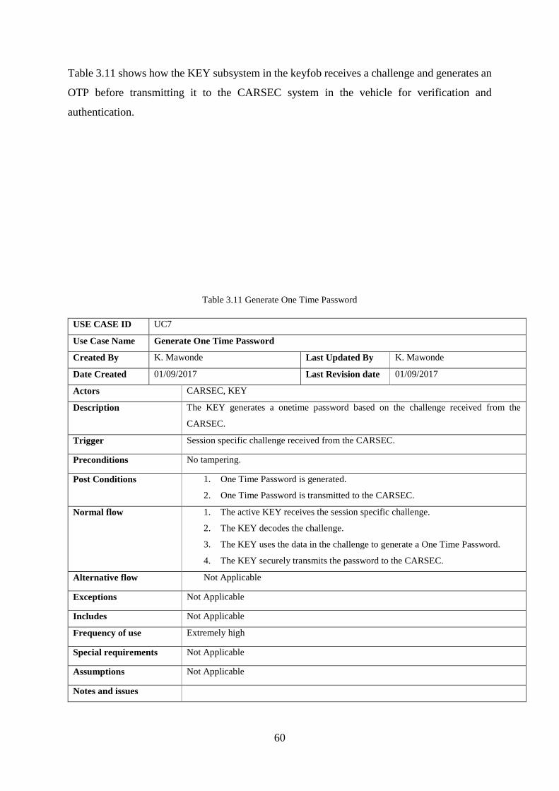
60
Table 3.11 shows how the KEY subsystem in the keyfob receives a challenge and generates an
OTP before transmitting it to the CARSEC system in the vehicle for verification and
authentication.
Table 3.11 Generate One Time Password
USE CASE ID UC7
Use Case Name Generate One Time Password
Created By K. Mawonde Last Updated By K. Mawonde
Date Created 01/09/2017 Last Revision date 01/09/2017
Actors CARSEC, KEY
Description The KEY generates a onetime password based on the challenge received from the
CARSEC.
Trigger Session specific challenge received from the CARSEC.
Preconditions No tampering.
Post Conditions 1. One Time Password is generated.
2. One Time Password is transmitted to the CARSEC.
Normal flow 1. The active KEY receives the session specific challenge.
2. The KEY decodes the challenge.
3. The KEY uses the data in the challenge to generate a One Time Password.
4. The KEY securely transmits the password to the CARSEC.
Alternative flow Not Applicable
Exceptions Not Applicable
Includes Not Applicable
Frequency of use Extremely high
Special requirements Not Applicable
Assumptions Not Applicable
Notes and issues

61
Table 3.12 details how the BLACKBOX subsystem uses its OBU to connect to other OBUs or
an RSU before transmitting log data to a proprietary server owned by the manufacturer after it
has been encrypted.
Table 3.12 Transmit encrypted log data
USE CASE ID UC8
Use Case Name Transmit encrypted log data
Created By K. Mawonde Last Updated By K. Mawonde
Date Created 01/09/2017 Last Revision date 01/09/2017
Actors BLACKBOX
Description The BLACKBOX transmits encrypted log data to the manufacturer
Trigger Connectivity with a Road Side Unit or mobile node.
Preconditions Connection has to be established.
Post Conditions Encrypted log data is transmitted.
Normal flow 1. The BLACKBOX securely receives log data from the CARSEC which it
encrypts.
2. The BLACKBOX connects to a Road Side Unit.
3. The BLACKBOX transmits the encrypted log data to the manufacturer’s
server.
Alternative flow Not Applicable
Exceptions Not Applicable
Includes Not Applicable
Frequency of use Extremely high.
Special requirements Not Applicable
Assumptions Not Applicable
Notes and issues Not Applicable

62
3.3.5 Sequence Diagrams
Sequence diagrams are used to detail the interactions of components within a system. This
implies the behaviour between different actors or actors and objects within the system. They
are used to model the functionality of the system by providing a detailed breakdown of the
functions of the system and the components or actors that trigger them. They also show the
relative actions taken by the system as a result of interaction with these objects or actors. For
the purposes of this study, a sequence diagram is used to show how the actors as components
of the security system, interact with each other and their behaviour under different scenarios.

63
Figure 3.4 Antitheft System Sequence Diagram

64
The Figure 3.4 details the operations of all the components that make up the system.
For the system to function as intended, some of the components will function upon the
completion of a condition and behave differently if the condition is not met as detailed
in the following conditions:
Condition 1: FingerprintStored
Initially when the manufacturer is programming the key for the owner (USER),
the KEY must not have any biometric information stored on it
(FingerprintStored =0) for the registration to be successful. If for any reason the
KEY has biometric information then steps are taken to remedy the situation.
Condition 2: FingerprintStored
This condition should be 1 after the user has been registered and only then can
the USER use their fingerprint to activate the KEY and unlock the car through
the CARSEC system.
Condition 3: FingerprintValid
When the USER attempts to authenticate themselves through their fingerprint,
this condition has to be met for the KEY to activate and interact with the
CARSEC. This acts as a layer of security which prevents unauthorised use of
the KEY or interception of signals from the KEY to the CARSEC for man in
the middle attacks.
Condition 4: KEYMessageValid
This condition is met after the USER is authenticated and as a result, the KEY
responds to the interrogation signal continuously transmitted by the CARSEC.
This acts as a prerequisite to further communication between the KEY and the
CARSEC.
Condition 5: KEYResponse
This condition is met when the CARSEC receives a response from the KEY
after which it sends a session specific challenge.
65
Condition 6: Challenge
This refers to the session specific challenge securely transmitted from the
CARSEC to the KEY and used by the KEY to calculate a one-time password
through cryptographic calculations.
Condition 7: OTPValid
When this condition is met (OTPValid=1), the vehicle would have compared
the one-time password sent by the KEY to the one internally generated in the
CARSEC using the same session specific challenge and found them to match.
Condition 8: ResponseValid
This condition is met after the one-time password is validated and the CARSEC
sends feedback to the KEY to show that the validation was successful. In the
event of an invalid response, the session is discarded and the process starts from
the beginning.

66
3.3.6 Activity Diagrams
Activity diagrams such as the one in Figure 3.5 detail the process followed by the system when
it is functioning as intended. They show the various activities within the system that occur and
clearly illustrate the progression from one process to the other thereby providing a more
informative view of how the system processes run. Activity diagrams are vital for their
illustration of the flow followed by the system when it operational which gives a deeper
understanding of the functionality of the system and the processes it conducts.

67
Figure 3.5 Antitheft System Activity diagram
68
3.3.7 System Design
This section presents a detailed structure of the system and its components. It discusses the
type of technologies used in the system to make it functional and provides an architectural view
of the system.
a) System Architecture
System architecture refers to the nature of the system in relation to the environment in which
it operates. It shows the design of the system under which it will satisfy its fucntional and non-
functionsl requirements. In context of the current study, the system architecture present in
Figure 3.6 shows the system and components around it required for it to function as intended.
It shows a diagramatic representation of the numerous components that work together to
achieve the intended function of the system. The red vehicle depicted has the proposed security
system within it and uses a wireless network to facilitate communication between the keyfob
and the vehicle. The vehicle has a blackbox system within it which stores security activity logs
and transmits them to the manufacturer’s proprietery server through the OBU to other OBUs
or RSUs.
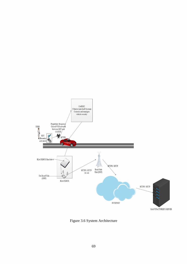
69
Figure 3.6 System Architecture

70
b) Components Detailed-Design and Requirements
System Components Detailed Design in Figure 3.7 details the technical specifications of
components that make up the system. It offers a detailed description of the current existing
technologies that can be used in the design as part of the system. These components offer
guidance in the design of the system.
Figure 3.7 describes the indivicual hardware components that can be used in the manufacture
of the security system’s components and shows how the subsytems work in conjuction with
each other to make up the overall security system. The subsytems KEY, CARSEC and
BLACKBOX that make up the system are described in detail following the figure.
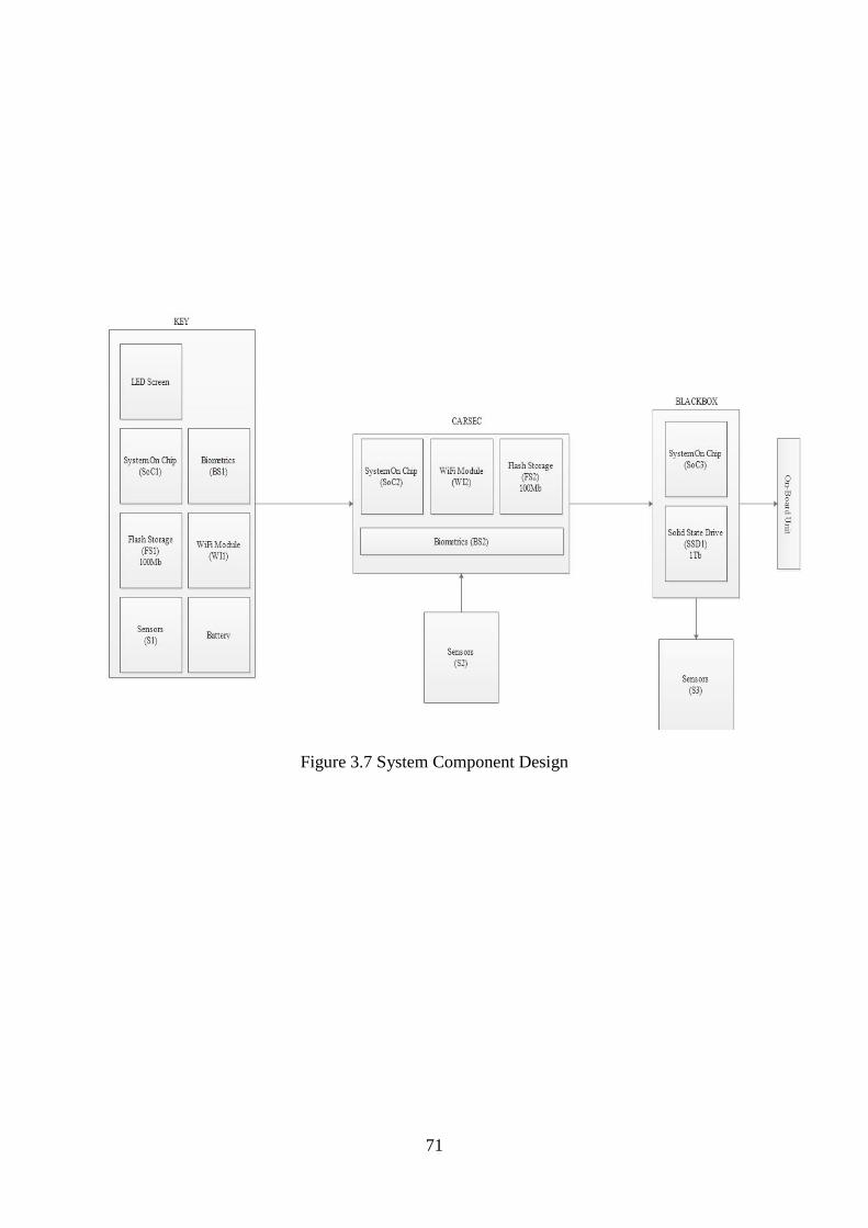
71
Figure 3.7 System Component Design

72
i. The KEY
Components of the KEY in the systems are as follows:
System on Chip (SoC1): SoC1 is a portable System on Chip similar to platforms used
for smartphones which has 1 GHz base clock on the processor and modules to process
biometric information and encryption. The system is designed to use as little energy as
possible for most functions with exceptions when cryptographic processes are running.
This enables encryption and decryption to be done at near instantaneous speeds.
Biometric Scanner (BS1): a highly portable ultrasonic and capacitive scanner built into
the key that works in conjunction with the SoC and a secure environment to store and
process fingerprint information.
Wireless interface (Wi-Fi) (WI1): a network interface that comes with limited
broadcasting capabilities. The interface is hardcoded to communicate with a single
SSID (CARSEC) and the interface cannot be reconfigured after the fact. The interface
operates on a proprietary frequency to avoid interference with other devices operating
on the common 2.4 GHz and 5 GHz bands used by most wireless devices. This further
secures the device’s communication. The SoC aids in communication by encrypting all
transmissions.
Flash Storage (FS1): the device contains a secure storage partition used to store the
biometric information which was initially registered by the user and other crucial
information.
Battery: a long lasting rechargeable unit essential for the operation of the device.
Sensors (S1): a variety of tamperproof sensors are used to secure the device against
physical tampering and to detect any faults with the key.
LED Screen: the key houses a tiny 0.5” LED Screen that displays status and feedback
information form CARSEC as well as any fault codes as detected by the sensors on the
KEY or in CARSEC.

73
ii. The CARSEC
Components of the CARSEC in the system are as follows:
System on Chip (SoC2): SoC2 is a portable System on Chip similar to platforms used
for smartphones which has 1 GHz base clock on the processor and modules to process
biometric information and encryption. The system is designed to use as little energy as
possible for most functions with exceptions when cryptographic processes are running.
This enables encryption and decryption to be done at near instantaneous speeds.
Biometric Scanner (BS2): a highly portable ultrasonic and capacitive scanner built into
the key that works in conjunction with the SoC and a secure environment to store and
process fingerprint information that is used in the vehicle as a contingent in the event
of hardware failure. The CARSEC receives biometric information from the KEY after
a user registers their fingerprint.
Wireless interface (Wi-Fi)(WI2): a network interface that comes with limited
broadcasting capabilities. The interface is hardcoded to communicate with a single
SSID (CARSEC) and the interface cannot be reconfigured after the fact. The interface
operates on a proprietary frequency to avoid interference with other devices operating
on the common 2.4 GHz and 5 GHz bands used by most wireless devices. This further
secures the device’s communication. The SoC aids in communication by encrypting all
transmissions.
Flash Storage (FS2): the device contains a secure storage partition used to store the
biometric information which was initially registered by the user and other crucial
information.
Sensors (S2): a variety of tamperproof sensors are used to secure the device against
physical tampering and to detect any faults with the vehicle and all components
connected to the security system of the car. Sensors on the vehicle may also be
connected to non-security essential components like the wiring harnesses, diagnostics
port and the connection to the BLACKBOX to further enhance tampering detection.

74
iii. The BLACKBOX
Components of the BLACKBOX is as follows:
Sensors (S3): a variety of tamperproof sensors are used to secure the device against
physical tampering and to detect any faults with the vehicle and all components
connected to the security system of the car. Sensors on the vehicle may also be
connected to non-security essential components like the wiring harnesses, diagnostics
port and the connection to the CARSEC to further enhance tampering detection.
System on Chip (SoC3): SoC3 is a portable System on Chip similar to platforms used
for smartphones which has 1 GHz base clock on the processor to perform encryption
using manufacturer specific encryption protocols which make the log data unreadable
to everyone else but the manufacturer.
On-Board Unit: used for V2I communication when log data is being transmitted to the
manufacturer’s server. The unit communicates with VANET enabled vehicles (V2V)
or RSUs and uses the connection to send the data to the database located on the
manufacturer’s server.
Solid State Drive: used to store log data produced by the system each time it is active.
The data is encrypted and stored. The data on the hard drive is transmitted to the
manufacturer’s server when the On-Board Unit is connected to an external node.

75
3.3.8 Network Architecture
In the context of this research, network architecture refers to the framework used to define the
attributes of a network from the devices in the network to the ways in which the devices
communicate with each other. It is used to illustrate the manner in which communication is
facilitated in a network through a diagrammatic overview as shown in Figure 3.6.

76
Figure 3.8 Network Architecture

77
The network connectivity of this system, as shown in Figure 3.8 is limited to transmitting
encrypted log data that is stored in the BLACKBOX to the manufacturer’s server through the
use of an OBU that communicates with RSU to facilitate the data transfer. The OBU of the
BLACKBOX actively seeks out connections with other OBUs and RSUs so that it can transmit
the data to the manufacturer’s server through them. The vehicle security system (CARSEC)
has no access to this connection and is completely isolated on its own proprietary closed
network. The CARSEC system sends log data to the BLACKBOX through a physical and
isolated connection with sensors in place to detect any hardware tampering in the form of the
communication cable being spliced into by a perpetrator.
3.3.9 System Algorithmic Design
In this section we present the algorithms of the system from Figure 3.9 to Figure 3.11, starting
with algorithms in the KEY part of the system, followed by the CARSEC’s algorithm and lastly
the BLACKBOX algorithm.
However, the following assumptions under which the system operates as stated as follow:
Assumptions
The system is functioning as intended with an active connection between the On-Board
Unit and a nearby Road Side Unit.
Potential (perpetrators) have neither the technology nor the knowledge at hand to
compromise the system without triggering the safety mechanisms in place.
The perpetrators do not have access to key programming hardware made available to
the manufacturer’s retailers.

78
a) The KEY algorithm
The algorithm below as shown in Figure 3.9 details the setup process of the key which is done
by the manufacturer’s retailer at the time of the vehicle’s purchase.
Pseudocode (Fingerprint Register)
If (FingerprintStored==0)
If (ManufactureIDValid==1)
{
Register Fingerprint;
FingerprintStored++;
SendFingerprint;
Return 0;
}
Else
Access Denied;
Else If(ReplaceFingerprint)
{If (ManufactureIDValid==1)
{
Delete Fingerprint;
FingerprintStored--;
Register Fingerprint;
FingerprintStored++;
SendFingerprint;
Return 0;
}
}
Else Return 0;
The Pseudocode above is used when setting up a key for a new owner and it works by checking
for a stored fingerprint (FingerprintStored) and if there is none, the manufacturer issued code
(ManufactureIDValid) is used by the retailer to allow a new fingerprint to be registered as
shown in Figure 3.9.

79
Figure 3.9 KEY algorithm to register fingerprint

80
The algorithm below as shown in Figure 3.10 shows how the key will function after it has been
succesfully setup and is being used by the registered user to access their vehicle.
Pseudocode (Fingerprint Authentication)
Read Fingerprint;
If (FingerprintStored==ReadFingerprint)
{
Respond to CARSEC;
If (ChallengeReceived)
{
Calculate OTP;
Trnasmit OTP to CARSEC;
Listen for response;
}
Break;
}
Return 0;
This pseudocode details how the key responds to CARSEC by authenticating the user first and
then responding to the interrogation signal sent by CARSEC or remaining inactive when
authentication fails as shown in Figure 3.10

81
Figure 3.10 Algorithm showing the normal operation of the KEY.

82
b) The CARSEC algorithm
The algorithm below as shown in Figure 3.11 shows the manner in which the vehicle security
system CARSEC functions.
Pseudocode (CARSEC)
If (KeyInRange)
{
Transmit Interrogation Signal;
If (KeyResponds)
{
Send Challenge;
Calculate OTP;
If (OTPRecevied)
If (OTPReceived==OTP)
{
Unlock vehicle;
Send Feedback Success;
}
Else
Send Feedback Fail;
Send log data to BLACKBOX;
}
Go to start;
}
Go to start;
In this Pseudocode and in Figure 3.11, CARSEC continuously checks for the presence of the
car key (KEY) and when the key is in range CARSEC transmits a continuous interrogation
signal. Once the key responds, CARSEC sends a unique session specific challenge and waits
for an OTP response form the KEY. Once the response is received, CARSEC compares it to
the OTP it generated using the same session specific challenge it sent to the KEY and if the
OTPs match, the vehicle is unlocked and a success signal is sent. All data is then sent as a log
to the BLACKBOX.

83
Figure 3.11 Algorithm detailing how the CARSEC functions.

84
c) The BLACKBOX
This algorithm shown in Figure 3.12 details the functionality of the blackbox whenever activity
is detected in CARSEC.
Pseudocode
If(VehicleActivity)
{
Receive log data from CARSEC;
Encrypt log data;
Store log data;
Transmit log data ot Manufacturer Server;
}
Goto start;
The pseudocode above and Figure 3.12 below shows how the BLACKBOX waits until activity
is detected with CARSEC and then a log is received and encrypted before being stored. When
the On-Board Unit that is part of the BLACKBOX is connected to a Road Side Unit, it transmits
the stored data to the Manufacturer’s Server.
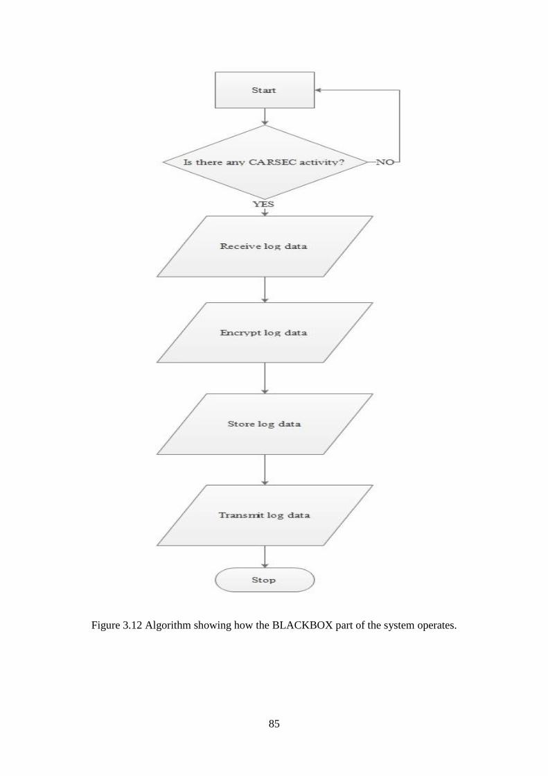
85
Figure 3.12 Algorithm showing how the BLACKBOX part of the system operates.
86
3.3.10 System Security
In terms of hardware security, the system uses sensors located on the hardware components
that make up the entire system. The sensors are in place to detect physical tampering in an
effort to bypass the security measures, for instance, splicing communication wires to intercept
secure data or opening up of the key to bypass the fingerprint and forcefully activate the key.
This is done in an effort to eliminate hardware vulnerabilities that are usually manipulated by
perpetrators.
The CARSEC communicates with the key wirelessly using a proprietary frequency so as to
avoid traffic detection and interception by tech savvy perpetrators. This minimises the potential
attack vectors that can be used by attackers to compromise the system and acts as a
complimentary measure to the system’s encryption. The use of device based session specific
information eliminates the probability of man-in-the-middle attacks or replay attacks as the
information expires as soon as it is produced and is not reusable.
3.3.11 Chapter Summary
In this chapter, we went through all the requirements of the system and detailed the way in
which the system functions including the components that go into each part of the system. We
discussed the way in which the system communicates with external networks and the way
individual components that make up the system communicate and interact with each other.

87
CHAPTER 4
SIMULATION SETUPS AND EXPERIMENTS
4.0 Chapter Outline
This chapter presents information on the simulations related to the study. This entails the
depiction of the scenarios under which the experiments were being conducted as well as a
description of the tools that were used to accomplish the intended goal. Moreover, it explains
the relation of the investigations to the overall goal of the study and addresses some aspects of
the practical parameters that were crucial areas of interest in this study. The purpose of this
chapter was to provide a practical scale of the functionality expected out of the theoretical
system that was proposed in this work.
4.1 Introduction
This research study was proposing a vehicle security system that addresses the weaknesses and
shortcomings of currently implemented security technologies through the use of a network-
based approach that aims to bolster the inherent security offered as well as a suite of security
features that make attacks or interception by an adversary difficult. The system is comprised
of individual subsystems that work in combination to form the overall security system in a
secure environment. To elaborate, the system has three main components, the KEY which is a
subsystem found in the keyfob of the vehicle, CARSEC which is the other subsystem which is
found in the vehicle and corresponds with the KEY and finally the BLACKBOX which is a
subsystem linked to the CARSEC through hard lines.
The KEY offers biometric authentication which is used to activate it for secure communication
with CARSEC including the transmission of corresponding cryptographic functions and the
generation and verification of a one-time password used to authenticate the particular session
and validate the identity of the user thereby eliminating the risk of replay attacks in the event
that an adversary captures transmitted data and decodes it.
The CARSEC subsystem communicates with the KEY using a closed wireless network after
the KEY has been activated and connected to the network when the identity of the KEY is
confirmed using the MAC address as well as a secret identifier tag that can be based off of the
key fob’s serial number. The CARSEC system verifies the OTP and communicates with the
vehicle through the ECU to unlock the vehicle and its corresponding functions for use.
88
The BLACKBOX subsystem’s primary functions are logging of activities and transmission of
the logs to an offsite server using an On-Board Unit (OBU) that communicates using vehicle
to vehicle (V2V) or vehicle to infrastructure (V2I) transmission to other vehicles and Road-
Side Units (RSU) respectively. This subsystem logs successful authentications, failed
authentications, intrusion attempts from unrecognized sources and attempts of physical
tampering.
This section details different scenarios in which the system will be able to operate, outlining
the system’s behaviour when certain conditions are met or imposed on it. It should be noted
that the scenarios in this instance do not include the normal function of the system of locking
and unlocking vehicle systems for the user, but instead focus on abnormal scenarios as follows:
Hijacking: in this scenario the user has already unlocked and started driving the vehicle
and by some unfortunate happenstance becomes the victim of a hijacking. Usually, in
such an event, the perpetrator would drive off leaving the owner abandoned on the side
of the road and the vehicle sensors would flag the opening of the door (or any door)
during operation and start a 30 second timer. After the timer elapses, the vehicle lets
off a notification sound to prompt for user’s biometric authentication upon which
failure to authenticate would cause the vehicle to cut the fuel feed, lock vehicle systems
and lock the vehicle itself. If another 30 seconds elapses without authentication the
vehicle’s hazards turn on and the BLACKBOX transmits an emergency signal to the
manufacturer’s server and indeed nearby mobile nodes. This mode will only be
deactivated after the user authenticates biometrically.
Initial theft: this scenario covers the off chance that a perpetrator has managed to
bypass the vehicle’s door locks and gained physical access to the vehicle. The sensors
would flag tampering and this would trigger the disabling of the fuel feed and locking
of all functions. This also prompts the BLACKBOX to send an emergency signal to the
manufacturer’s server. A valid fingerprint entry would bypass this mode and resume
normal function.
Hardware failure: in the event that CARSEC or KEY malfunction through a hardware
fault or otherwise of the KEY, there is a designed bypass to enable vehicle access to
the owner. While the system is keyless, the physical key fob has a traditional key in it
that can be used to physically unlock the vehicle’s doors. However this does not unlock
89
the vehicle functions. To unlock hardware functions in such a situation, the user inputs
their fingerprint into a backup reader located in the vehicle. It should be noted that there
is no alternative if the fault is on the vehicle side or affects CARSEC short of contacting
or going to the manufacturer to rectify the problem.
Vehicle tampering: in this scenario, a tech savvy perpetrator has managed to gain
physical access to the vehicle and they are trying to physically compromise CARSEC’s
functionality by intercepting data between the system’s components through a hardware
tap. The sensors will flag the tampering and CARSEC will take the appropriate
measures to prevent interception like rerouting data through alternative communication
lines and going into emergency mode. Once hardware tampering is detected at this
level, it is disabled by a two factor unlock comprising of the owner’s fingerprint and
valid manufacturer credentials.
4.2 Focus and Scope
The practical implementation of the vehicle security system that is proposed in this study would
require a substantial amount of capital to design the keyfob as specified by the hardware
requirements mentioned in Chapter 3, which not only requires specialized components, but
designers and engineers to design an appropriate form factor that is portable and does not
compromise the functionality of the device. The same capital would be required to design the
other two subsystems that make up the overall system and a vehicle to modify and implement
the system in, all of which are unavailable to us.
Due to limiting factors such as the lack of access to a design laboratory and the capital to
purchase components and build the system, we have limited the scope of the practical part of
the study to simulations of various critical components that would be found in the system in an
effort to offer insight on how the components would function in such an environment under
our configuration. This therefore means that the practical aspect of this study will be limited to
the demonstration of the one-time password generation, transmission of the password over a
wireless network and the information obtained from attempting to intercept the transmission
using an adversary’s device. The focus is on attempting to successfully intercept and decrypt
the transmitted device and thereby obtain the security information being transmitted between
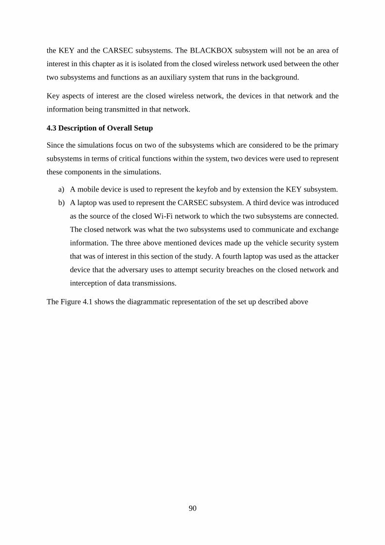
90
the KEY and the CARSEC subsystems. The BLACKBOX subsystem will not be an area of
interest in this chapter as it is isolated from the closed wireless network used between the other
two subsystems and functions as an auxiliary system that runs in the background.
Key aspects of interest are the closed wireless network, the devices in that network and the
information being transmitted in that network.
4.3 Description of Overall Setup
Since the simulations focus on two of the subsystems which are considered to be the primary
subsystems in terms of critical functions within the system, two devices were used to represent
these components in the simulations.
a) A mobile device is used to represent the keyfob and by extension the KEY subsystem.
b) A laptop was used to represent the CARSEC subsystem. A third device was introduced
as the source of the closed Wi-Fi network to which the two subsystems are connected.
The closed network was what the two subsystems used to communicate and exchange
information. The three above mentioned devices made up the vehicle security system
that was of interest in this section of the study. A fourth laptop was used as the attacker
device that the adversary uses to attempt security breaches on the closed network and
interception of data transmissions.
The Figure 4.1 shows the diagrammatic representation of the set up described above

91
Figure 4. 1 Diagrammatic representation of Experiment setup

92
4.4 Modules Description
For the purpose of the experiment the wireless network adapter was treated as an individual
module bringing the total number of modules of interest to four, including the CARSEC, KEY
and the attacker device.
4.4.1 The Wireless Network Adapter
The Wireless Network Adapter is a module in this experiment which is responsible for
facilitating the wireless network that is used for communication between the CARSEC and
KEY subsystems and a target for the attacker device. It is responsible for determining the
security protocols used to secure the communication channel and the Wi-Fi network properties
such as the ESSID and the passphrase. The module is device type independent, meaning it can
be a mobile smartphone capable of producing a Wi-Fi hotspot that shares its internal mobile
data connection, to an access point connected to an Ethernet cable such as another laptop, router
or microcomputer platform. In this experiment, one device was used as this module, namely a
Xiaomi Mi A1 smartphone running Android 8.1 [106] Oreo using a mobile hotspot shown in
Figure 4.2 below.
Figure 4. 2 Wireless Network Adapter
4.4.2 CARSEC
The CARSEC module was a laptop with wireless connectivity capabilities. While the model is
irrelevant in the conduction of the experimentation, the model in use in this case was a MSI
GL62m laptop with an Intel Killer Wi-Fi adapter and running Windows 10 [107] as shown in
Figure 4.3. It is used to log traffic information as a controlled test illustrating the unencrypted
data transmitted between it and the KEY and ultimately the information that is the end goal for

93
the attacker in their interception of the communications between the CARSEC and KEY
modules.
Figure 4. 3 CARSEC
4.4.3 KEY
The KEY module was a mobile device with wireless connectivity capabilities. While a variety
of devices can be used to represent this module, this scenario utilizes a Xiaomi Redmi Note 4
running Android 7 Nougat [106] as shown in Figure 4.4. This module provided information on
the type of functions being used to calculate the one-time password as well as the mechanism
for transmission to the CARSEC module.
Figure 4. 4 KEY
4.4.4 Attacker Device
This module was a laptop with wireless connectivity capabilities and in this particular scenario,
it was an Asus A555LB running Windows 10 as the primary operating system as shown in
Figure 4.5 below. It is used to intercept the transmissions between the CARSEC and KEY
modules.

94
Figure 4. 5 Attacker Device
4.5 Setting up of Individual Modules
4.5.1 Wireless Network Adapter
This module was configured to use a 2.4 GHz band network secured through the use of WPA2
PSK and a password which was eleven characters long. The cipher suite built in to WPA2 PSK
was considered to be sufficient to secure communication between the devices in the network,
with other augmentations considered as mentioned in Figure 4.6.
Figure 4. 6 Secure wireless communication setup on the Wireless Network adapter module

95
4.5.2 CARSEC
This module uses Windows 10 and was connected to the wireless network configured above
by the Network Adapter module. There are a couple of open source programs used to
collectively simulate the functionality of CARSEC in this experiment, namely syncthing [108]
to facilitate synchronization between the CARSEC and KEY modules over the established
connection. This program was sourced from GitHub and pairs the KEY and CARSEC module
by establishing a shared secret key used in the transmission of information and thereby offering
an additional layer of security over the standard offered by 802.11q. Syncthing is setup on
Windows and runs in a web based interface as shown in the Figure 4.7.
Figure 4. 7 Syncthing on CARSEC
4.5.3 KEY
This module runs three applications to simulate the functionality of the KEY. It runs the
companion application of the open source program Syncthing[108] which was used to
complete the communication between the two devices as shown in Figure 4.8. Syncthing is an
open source and trustworthy application that offers users the ability to synchronize data
between a multitude of devices without the restrictions and governance of a central server like
in cloud synchronization. This gives the user full control over their data.

96
Figure 4. 8 Syncthing configured on the KEY module
The corresponding applications connect the two modules and prepare for synchronization
between the two as shown in Figure 4.9.
Figure 4. 9 Syncthing connected from CARSEC to KEY
The second application is called AndOTP[109] which utilizes the Time One Time Password
algorithms utilized in most two factor authenticator applications such as Google Authenticator.
This enables the use of system time to synchronize cryptographic functions that produce the
OTP in a way that does not cause an out of synchronization password to be generated, thereby
reducing the chances of false positives. The application is also open source from GitHub and
is shown in Figure 4.10.
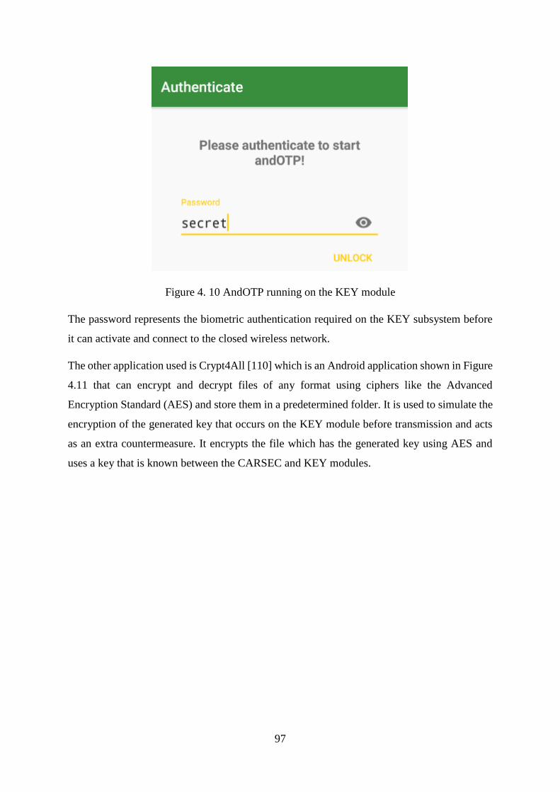
97
Figure 4. 10 AndOTP running on the KEY module
The password represents the biometric authentication required on the KEY subsystem before
it can activate and connect to the closed wireless network.
The other application used is Crypt4All [110] which is an Android application shown in Figure
4.11 that can encrypt and decrypt files of any format using ciphers like the Advanced
Encryption Standard (AES) and store them in a predetermined folder. It is used to simulate the
encryption of the generated key that occurs on the KEY module before transmission and acts
as an extra countermeasure. It encrypts the file which has the generated key using AES and
uses a key that is known between the CARSEC and KEY modules.

98
Figure 4. 11 KEY uses shared password to encrypt password file
4.5.4 Attacker Device
This module is configured to run a live version of Kali Linux [111] as shown in Figure 4.12, a
distribution of Linux specialized for penetration testing and suitable for use in attacking and
intercepting the closed network in which the CARSEC and KEY modules communicate.
Figure 4. 12 Attacker device running a live version of Kali Linux

99
Kali Linux is able to configure the wireless adapter on the attacker device to capture traffic
from numerous wireless networks and contains a suite of tools that can be used to analyse the
captured data.
4.6 Simulation Setup
This section of the chapter details the manner in which the simulations were conducted. The
various functions of the different modules are detailed as well as the manner in which they fit
into the overall system in terms of functionality and chronological operations. The sequence
was divisible into four phases, namely the setup of the network, the setup of the attacker device,
the generation and transmission of the password and the capture of the network traffic by the
attacker device.
4.6.1 Network Setup
The network is set up using the Xiaomi Mi A1’s mobile hotspot feature as shown in Figure 4.6
above. The CARSEC module was configured by connecting the MSI laptop to the wireless
network as shown in the Figure 4.13.
Figure 4. 13 CARSEC connected to the closed secure wireless network

100
The KEY module was configured through connecting the Xiaomi Redmi Note 4 mobile device
to the wireless network as shown below in Figure 4.14.
Figure 4. 14 KEY connected to the closed secure wireless network
After the initial setup, both devices used as CARSEC and KEY modules can automatically
connect to the secure wireless network.

101
4.6.2 Setup of Attacker Device
The attacker device was running a live version of Kali Linux and now needed to be configured
for it to capture wireless traffic from a foreign network. This was accomplished through the
steps detailed below.
Figure 4. 15 checking wireless interfaces
The attacker confirms that the hardware in use has a wireless interface through the use of the
iwconfig command shown in Figure 4.15 above.
Figure 4. 16 checking the capabilities of the wireless adapter
The attacker then checks if the hardware in use has the capability to capture the network traffic
using the iw list command. This is confirmed with the presence of the active monitor as shown
in Figure 4.16 above.
Figure 4. 17 setting promiscuous mode on
The attacker switches in promiscuous mode as shown in Figure 4.17 above.

102
Figure 4. 18 configuring a monitoring interface
As shown in Figure 4.18, the attacker configures the monitor interface and kills all programs
that may disrupt its functionality using the airmon-ng start command on the wireless interface.
Figure 4. 19 Confirming the monitor interface is active
The attacker confirms the activation of the monitor interface by checking wireless interfaces
again as shown in Figure 4.19 above.
Figure 4. 20 Scanning for networks
Figure 4. 21 Results of Network Scanning

103
The attacker uses the command in Figure 4.20 to obtain the results in Figure 4.21. If the network
of interest is the only network available or if the attacker knows the ESSID of the network,
they can isolate the network and monitor it as shown in the figure below.
Figure 4. 22 Isolate channel of interest and capture traffic
Figure 4. 23 Capture isolated network traffic
The network of interest is targeted for traffic capture as shown in Figure 4.22 and the attacker
now waits for activity on the network as shown in Figure 4.23.
4.6.3 Generation and transmission of the password
AndOTP is used to generate the TOTP as shown in Figure 4.24 below.
Figure 4. 24 TOTP generation by AndOTP
The generated password is encrypted as an additional countermeasure against network traffic
decryption by an attacker as shown in Figure 4.11 to produce the AES encrypted file shown in
Figure 4.25.
Figure 4. 25 Encrypted file containing password
The encrypted file containing the password is synced from the KEY to CARSEC as illustrated
by Figures 4.26 and 4.27 respectively below.
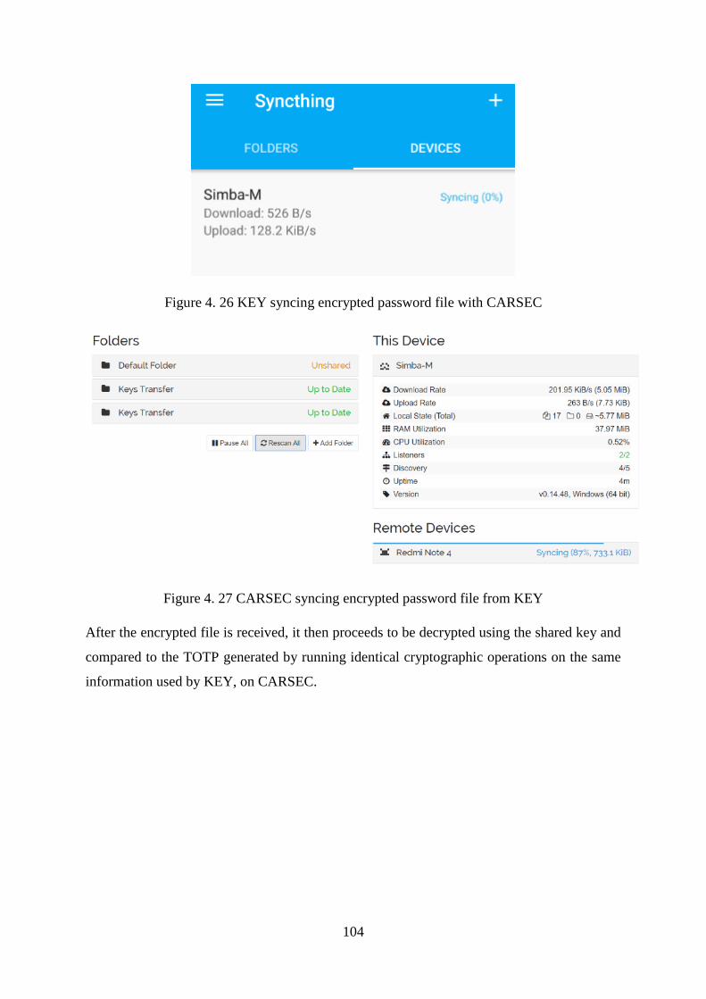
104
Figure 4. 26 KEY syncing encrypted password file with CARSEC
Figure 4. 27 CARSEC syncing encrypted password file from KEY
After the encrypted file is received, it then proceeds to be decrypted using the shared key and
compared to the TOTP generated by running identical cryptographic operations on the same
information used by KEY, on CARSEC.
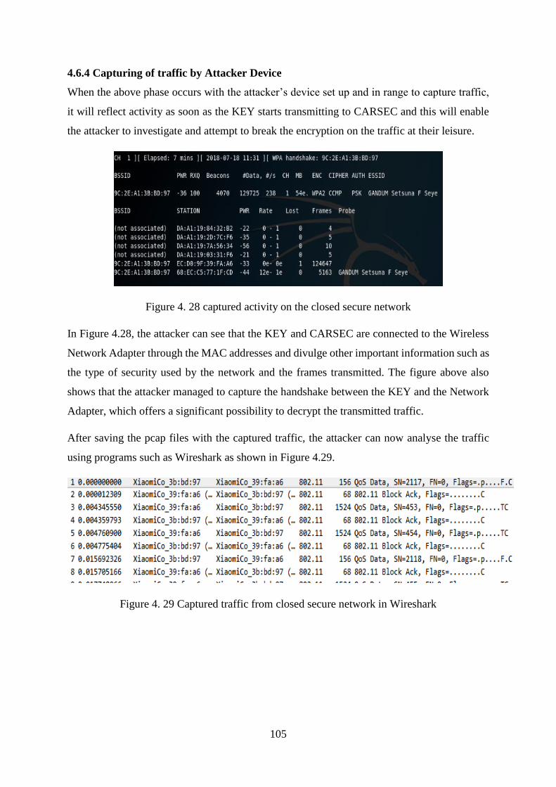
105
4.6.4 Capturing of traffic by Attacker Device
When the above phase occurs with the attacker’s device set up and in range to capture traffic,
it will reflect activity as soon as the KEY starts transmitting to CARSEC and this will enable
the attacker to investigate and attempt to break the encryption on the traffic at their leisure.
Figure 4. 28 captured activity on the closed secure network
In Figure 4.28, the attacker can see that the KEY and CARSEC are connected to the Wireless
Network Adapter through the MAC addresses and divulge other important information such as
the type of security used by the network and the frames transmitted. The figure above also
shows that the attacker managed to capture the handshake between the KEY and the Network
Adapter, which offers a significant possibility to decrypt the transmitted traffic.
After saving the pcap files with the captured traffic, the attacker can now analyse the traffic
using programs such as Wireshark as shown in Figure 4.29.
Figure 4. 29 Captured traffic from closed secure network in Wireshark

106
4.7 Test Parameters
The simulations as shown in Figure 4.30 were conducted under three variations and from two
perspectives:
The controlled simulation is from the point of a user who has system level access and can
analyse internally generated traffic. This is the perspective of a technician as it offers
information that would not even be available to the vehicle owner or end user. The above
mentioned perspective will cover both open and secure wireless networks as the security level
on the network does not affect the amount or level of information accessed by an individual
with such access. The metrics of concern in this variation of the simulation are Throughput and
Round Trip Time as they will be used to assess the performance of the wireless network which
is being used in the security system.
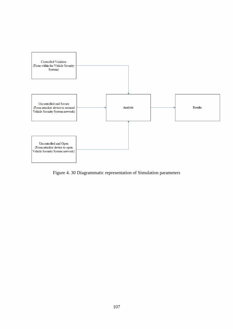
107
Figure 4. 30 Diagrammatic representation of Simulation parameters

108
The second and third variations are both from the perspective of the attacker and attacker
device. The difference between the two variations is that one is monitoring a secure network
whilst the other is monitoring an open network. It is worth noting that the variation of
importance is the one with the attacker targeting the secure network, as it is a more realistic
representation of a practical scenario which could occur in the real world. The quantitative
metric for the scenarios in the second and third variations is the packet flow graph which shows
the packets transmitted against time. This indicates the ability of the attacker device to intercept
the secured traffic and the amount of traffic that is captured in relation to the traffic transmitted
in the network of interest. The other result of interest lies in the transmissions captured by the
attacker device, with a similarity to the transmission in the controlled variation being used to
determine the success or failure of the attack.

109
4.8 Testing Environments
The simulations were conducted in three environments which are overly similar in terms of the
setup but varied in the level of access to the security system and the level of security of the
network being utilized. In all two setups, the CARSEC and KEY modules connect to a network
in the same manner with the variation being a result of the level of access to the system. This
means that both simulations use devices that are connected to a closed secure network.
In the first scenario of the simulations shown in Figure 4.31, the data transmitted was logged
directly from CARSEC giving the user unfettered access to the system’s communication
infrastructure and by extension, access to the data before it is encrypted and transmitted and
the received data after decryption. It is worth noting that this version of the experiment does
not reflect the access level that is granted as a result of an attack but rather the access level
granted to manufacturer technicians who run diagnostics on the system and furthermore it acts
as a control set of data as it serves to indicate the kind of data expected to be obtained by an
attacker in the event of a total and successful system compromise.

110
Figure 4. 31 Elevated data access level in the first scenario

111
The second scenario that is shown in Figure 4.32 is the most probable one as it is from the point
of view of the attacker instead of a technician like the scenario above. It shows information
from the view of the attacker who has no prior access or information and is trying to
compromise the vehicle security system through intercepting the transmitted data between
CARSEC and KEY.
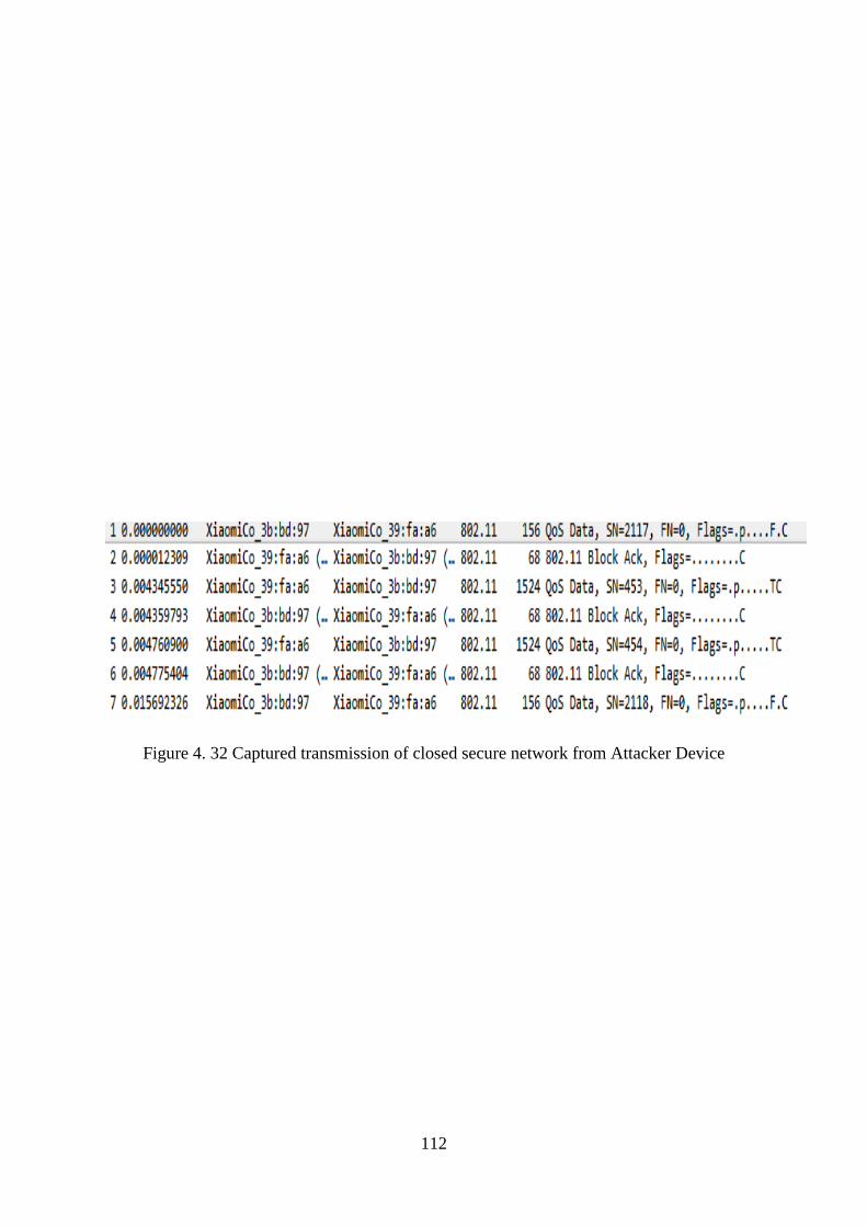
112
Figure 4. 32 Captured transmission of closed secure network from Attacker Device

113
The third scenario that is shown in Figure 4.33 uses an open wireless network. This scenario
does not represent a realistic implementation since the use of an open network would hinder
the strength of security that the system aims to achieve. In an actual vehicle security system,
the use of an open network would be nothing but an additional attack vector that can be
manipulated by an adversary to compromise the vehicle’s security.

114
Figure 4. 33 Captured traffic on open wireless network

115
4.8 Chapter Summary
This chapter covers details of the simulation experiments relevant to this study. It involves
specifying parameters under which the simulations are run and the components that are
involved in the simulations. It details simulation components and relates them to modules or
subsystems that are part of the vehicle security system in question. Finally it details the
scenarios under which the experiments are run.
116
CHAPTER 5
RESULTS AND DISCUSSION
5.1 Chapter Outline
This chapter evaluates and discusses the results obtained from the simulations conducted in the
previous chapter. It also addresses some of the metrics of interest in this study that are used to
offer insight into the evaluation process.
5.2 Simulation Results – Controlled Variation
The controlled experiment reflects the data access level that is viewed from the perspective of
the manufacturer technician or mechanical specialist working with or on the vehicle and
subsequently the vehicle system on behalf of the manufacturer or car dealer. Form this point
of view, diagnostic information as well as unencrypted data transmissions can be observed.
This is a high level of access only afforded to official technicians with the appropriate
equipment for the purposes of running diagnostics and monitoring system performance,
therefore if an attacker were able to obtain this level of access to the vehicle system, it would
be a clear indicator of complete system compromise. This is therefore essentially a control to
reflect the possible results of a complete system compromise and will be what the attacker will
aim to achieve through decrypting captured traffic data. The level of access in this variation of
the experiment offers the opportunity to monitor metrics that are otherwise unavailable for
analysis in any other situation and therefore Throughput and Round Trip Time will be the
metrics of interest in this scenario as well as a view of data transmission logs and the type of
information openly available to the technician.
Throughput refers to the rate at which data is transmitted in a network while Round Trip Time
refers to the time taken by a signal to reach its destination from its source and for the response
to that particular signal to be received.
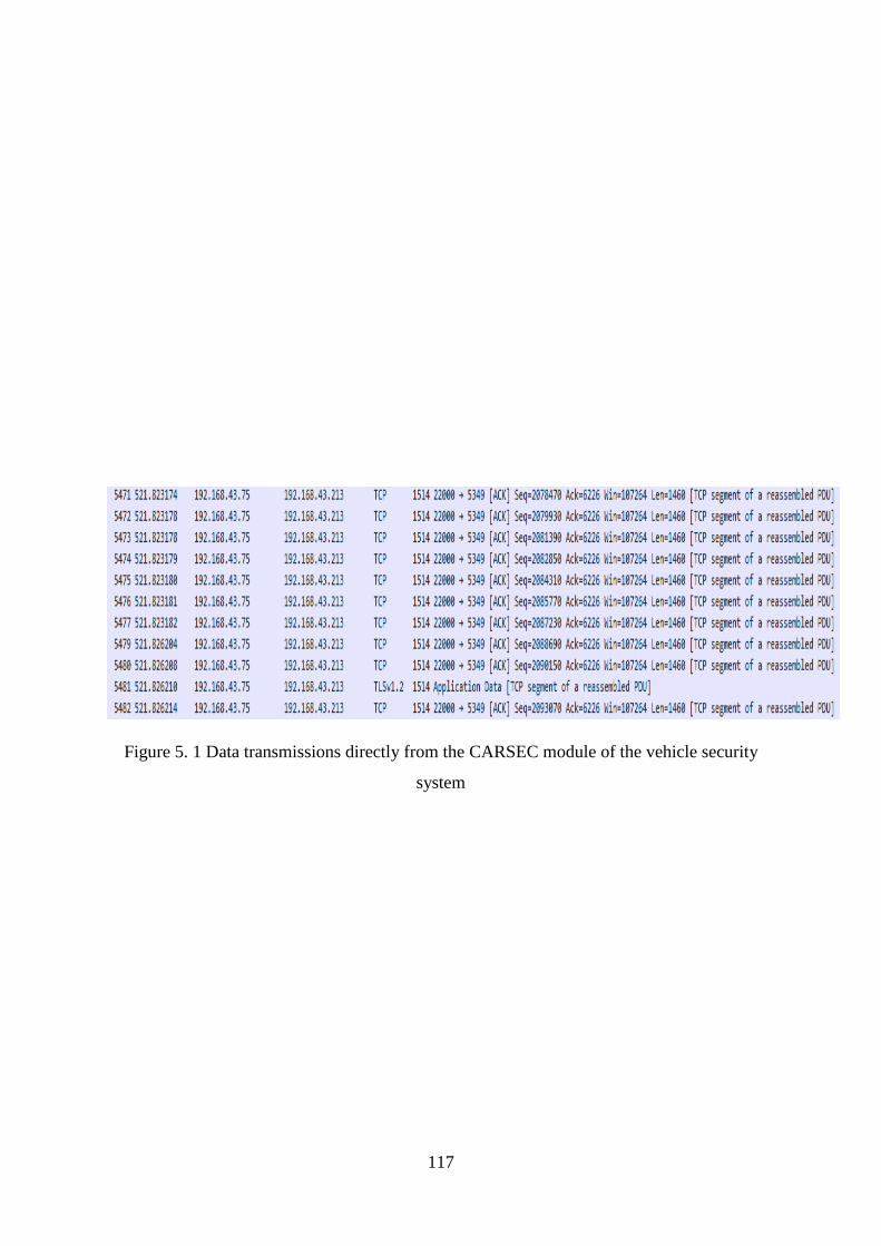
117
Figure 5. 1 Data transmissions directly from the CARSEC module of the vehicle security
system

118
In Figure 5.1, the technician has access to all the information being transmitted from and
received to the vehicle including traffic from the CARSEC system itself. This kind of access
to information is meant to help in diagnosis and repair. Figure 5.1 also gives details of the
source and destination of the transmission, as well as the protocol in use together with the ports
used. It also describes packet information that is significantly useful to anyone with the
technical knowhow as it can be used to profile the system.
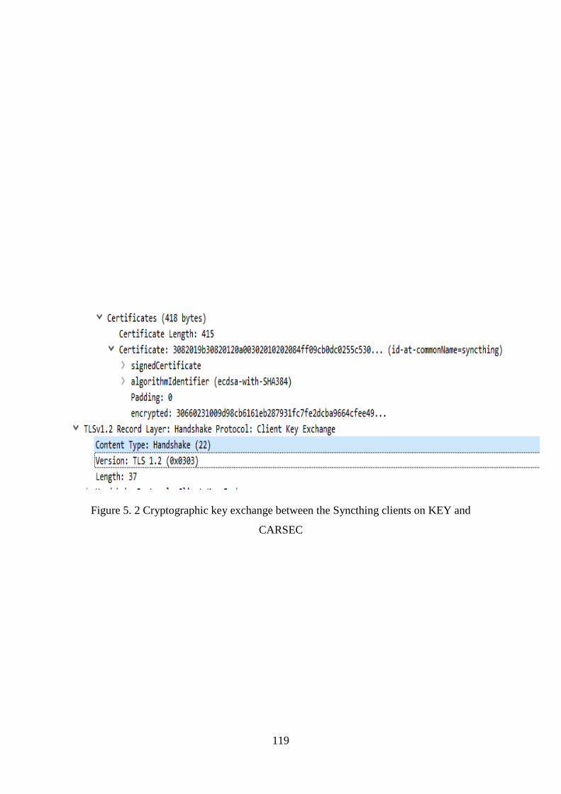
119
Figure 5. 2 Cryptographic key exchange between the Syncthing clients on KEY and
CARSEC

120
Figure 5.2 shows a key exchange between Syncthing, the application used to facilitate
synchronization between the CARSEC and KEY modules thereby allowing secure
transmission of data between the vehicle and its key. It is using Elliptical Curve Digital
Signature Agreement algorithm with Secure Hash Algorithm (SHA384) and this combination
ensures security against practical attacks as it is up to specifications with the requirements of
NSA Suite B. This coupled with the inherent security found in the wireless standard 802.11q
which is being used by the network ensures that even if the security of the network is
compromised, there will still be an extra layer of security for the attacker to get through.
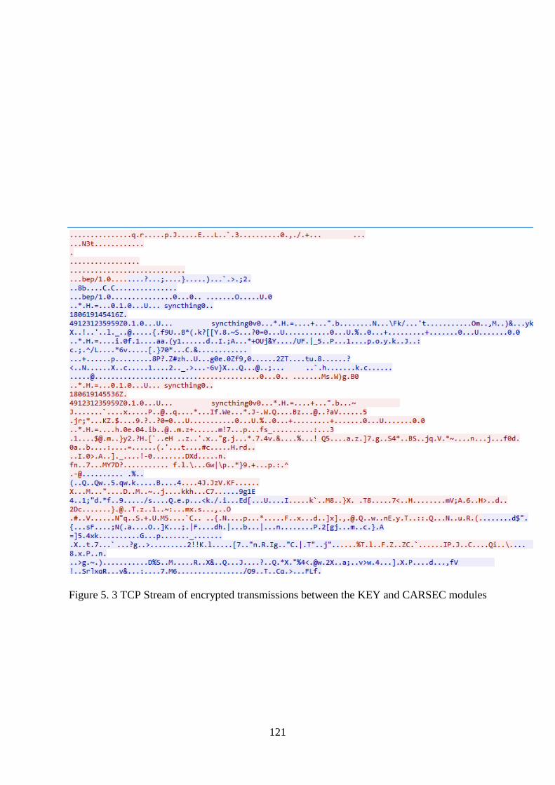
121
Figure 5. 3 TCP Stream of encrypted transmissions between the KEY and CARSEC modules

122
Figure 5.3 shows the TCP stream from the data transmission captured on the vehicle, as viewed
by someone with technician access level. While most of it appears to be abstract, it does
mention “syncthing” and under the right circumstances and knowhow can be used to extract
more information.
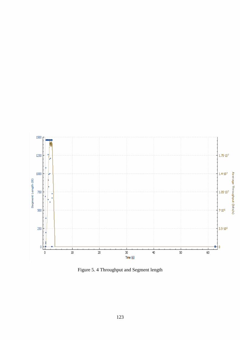
123
Figure 5. 4 Throughput and Segment length

124
The Figure 5.4 above shows the throughput recorded from the CARSEC and KEY modules on
the secured wireless network. It details the length of the segments transmitted as well as the
average throughput.

125
Figure 5. 5 Zoomed in version of Throughput and segment length graph

126
Figure 5.5 provides a more detailed and zoomed in version of Figure 5.4 before it, clearly
indicating the segment length and average throughput over time. The transmission showed
segments consistently at 1460 and an Average Throughput ranging from just over 2.375 Mb/s
to around 2.5 Mb/s during peak transmission. This shows consistent performance on the part
of the network stability and transmissions around the 2 Mb/s which are more than sufficient
for the system to work optimally.

127
Figure 5. 6 Round Trip Time

128
The Figure 5.6 above shows the highest RTT between 5.6 ms and 5.8 ms at the 2 s mark after
which it fluctuates up to the 4 s mark and then hits a low of 0.06 ms before rising steadily over
60s to just over 0.2 ms. In reality even the peak RTT would not be noticeable in normal
operation as the delay would be too minute for the user to be concerned.
5.3 Simulations Results – Uncontrolled and Secure Variation
This variation of the simulation is the one that reflects an actual attack on the vehicle security
system. It simulates the attacker’s use of specialized hardware to capture the transmission in
the closed network in which the KEY and CARSEC operate in an effort to decrypt the traffic
and profile the system as a precursor to compromising the system and gaining access to the
vehicle. Unlike the earlier variation, the access that the attacker has is highly limited and should
only be identical to the one in the previous variation when the attacker has successfully
compromised the vehicle security system. This variation of the simulation has a basic access
to packet flow and that is the metric which will be used to assess the success of capturing
transmitted data. The other analysis will be on the captured data and will be used to determine
the success or failure of the attack on the system.

129
Figure 5. 7 Traffic from vehicle security system

130
Figure 5.7 shows a graphical representation of the traffic transmitted by the vehicle security
system as observed by the attacker. The presence of anything above a flat line is enough to
indicate that the capture device being used by the attacker is functioning properly and as
indicated above, over 600s the attacker captured fluctuating amounts of data being transmitted
with the highest peak being around 500 Kbits/s.

131
Figure 5. 8 capture statistics from attacker's device

132
The statistics in Figure 5.8 above show the amount of traffic from the vehicle security system
detected by the attacker’s device. From the figure above, the device being used by the attacker
managed to capture 100% of the traffic it detected coming from the vehicle security system.

133
Figure 5. 9 Captured transmissions of KEY on the vehicle wireless network

134
Figure 5.9 shows transmission of data blocks between modules in the vehicle security system
through the secure wireless network. While information such as the type of data being
transmitted is hidden from the attacker, other information such as the MAC addresses of the
devices and the device names, is visible to the attacker and that is a cause for concern as such
information can be used by the attacker to profile the architecture of the security system in the
vehicle. The attacker can also investigate weaknesses found in the individual hardware in an
effort to discover an attack vector.

135
Figure 5. 10 Captured transmissions of CARSEC on the vehicle wireless network

136
Figure 5.10 also shows transmission of data between modules in the vehicle security system.
While the information is still not as open as it can be, the figure details acknowledgements and
Quality of Service (QoS) data that can be used by the attacker to gain more information about
the system.

137
Figure 5. 11 Captured wireless network handshake on attacker's device
138
In Figure 5.11 above, the attacker’s device indicates that it has captured a WPA handshake
between two modules in the vehicle security system. This means that the attacker was able to
capture security transmissions between the KEY and CARSEC where the key fob of the vehicle
was connecting to the closed secure wireless network. This is obviously a problem as it further
aids the attacker in their endeavour to compromise the vehicle security system, as the captured
security information can be used to decipher the captured transmission. While the design of the
system is meant to counter such compromises, it does not stop the attacker from analysing how
the modules communicate through the captured information.
Despite all the information captured by the attacker as shown in the figures above, the attacker
has not managed to obtain the level of information access that was shown in Figures 5.1 to 5.5
above and therefore has failed to completely compromise the vehicle’s security system.

139
5.4 Simulation Results – Uncontrolled and Open Variation
This variation of the simulation is not an accurate representation of the real world scenario as
it would be counterproductive for a manufacturer to implement a security system that utilizes
an open wireless network for its communications. It is meant to provide insight into the type
of information that could be captured by an attacker as a result of poor implementation by the
manufacturer as historically evidenced with some new technologies introduced into production
with critical flaws.

140
Figure 5. 12 traffic from a vehicle security system using an open network

141
Over a period of 320s, the attacker captured data transmissions between the vehicle security
modules using the open wireless network with a peak of 1 Mb/s.
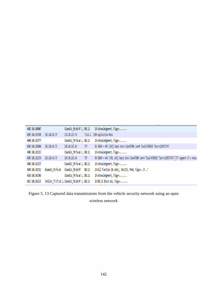
142
Figure 5. 13 Captured data transmissions from the vehicle security network using an open
wireless network

143
As expected, in Figure 5.13 the attacker is able to capture the transmission data that not only
shows the devices acting as modules in the vehicle security system, but their IP addresses as
well. The attacker is also able to obtain details about the data transmitted including the
protocols and the type of data. This indicates that with the exception of the encrypted payload
that needs further deciphering, the attacker is otherwise able to completely compromise the
security system with little difficulty thereby reinforcing the inefficiency and inadequacy of an
open wireless network in a security system.
144
5.5 Evaluation and Discussion
The results indicate that the attempt by an attacker to compromise transmitted data from the
vehicle security system through interception and decoding will be met by various challenges
due to the security measures built into the communication infrastructure being used. The use
of a secured wireless network on top of data that is encrypted beforehand through other security
mechanisms ensures that the attacker has to go through a multitude of security layers in order
to obtain the original data and thereby faces a challenge which severely reduces the probability
of success. This was deduced through the comparison of the captured data from the attacker
device and the captured transmission logs in the controlled variation of the simulation which
was from within the security system.
In comparison to other existing systems, the proposed security system presents the most
complex solution that addresses most if not all of the weaknesses shared amongst security
systems. The RFID systems based on rolling code algorithms have been proven to be weak
cryptographically due to the limitations in the architecture of RFID based devices and they
have also been breached through the use of replay attacks. This is because the transceiver
continuously broadcasts without the user’s knowledge. The proposed system addresses all
these shortfalls by using technology and communication mechanisms that can support Top
Secret level cryptographic countermeasures and can fully utilize cypher suites and different
cryptographic algorithms that ensure confidentiality and security. The use of a Time based One
Time Password as a fundamental function of the security system ensures that even in the event
of the capture and decoding of transmitted data, the captured credentials will not work because
they will have expired. The use of biometrics to authenticate the user and activate the keyfob
and by extension, the KEY subsystem, ensures that there are no unwarranted transmissions that
can potentially leak information even when the key is probed by a rogue signal.
While most vehicle security systems handle the issue of theft though checking for the key
within the vehicle, they do not account for hijack scenarios since the key may still be present
whilst the owner is not. The proposed security system addresses this through the use of re-
verification where the opening of any doors or switching off of the vehicle results in the keyfob
arming itself and needing re-entry of the fingerprint within a 30-second window. This ensures
that only authorized users are in possession of the keyfob and operating the vehicle.
Whilst the argument can be made that the use of a network based approach can introduce
additional attack vectors that can be utilized by the attacker, a justification can be made in that

145
current vehicle technology already exhibits connectivity in one form or the other meaning the
attack vector is already in play. This means implementing the security system would not add
any foreign vectors, but instead would bolster the security on all the other vehicle subsystems
through the use of anti-tampering communication busses and sensors to detect breaches.
Additionally, potential vectors are known and can be accounted for during implementation
since the technology being used is more than capable of ensuring a secure system.
5.6 Chapter Summary
In this chapter, an analysis on the results was conducted where the controlled and uncontrolled
variations of the simulation were investigated. The results showed the efficiency in the
implementation in the minimal amount of information that the attacker was able to obtain and
showed the strength of the implementation in the robustness of the security and the abstraction
of critical data transmitted between the subsystems/ modules of the vehicle security system. It
also analysed the ineffectiveness of implementing an open network in such a security system.
146
CHAPTER 6
CONCLUSION AND FUTURE WORK
6.1 Chapter Outline
This chapter summarises the previous chapters and provides a conclusion based on the results
obtained in the previous chapter. It also provides insight into potential areas of improvement
and highlights the numerous ways in which the improvements can be conducted.
6.2 Summary
This study was divided into six chapters. A brief summary of all the chapters is detailed below.
Chapter 1 was the introduction in which the problem was stated and the goal formulated. From
the goal, objectives were formulated as a means of tackling the research problem and a
preliminary literature study was conducted.
Chapter 2 was the literature review on vehicle security. The prospective solutions and
underlying technologies were also investigated in detail. Key aspects such as RFID were
covered under the section of currently implemented technologies and their strengths and
weaknesses were detailed. Alternative security mechanisms such as biometrics were also
investigated as well as networking technologies integrated in new generation vehicles as part
of the infotainment systems. This chapter answered the first research question (RQ1) and also
addressed the sub-questions RQ 1.1 and 1.2 through an exhaustive review of the related
literature.
Chapter 3 was where the research methodologies and research methods were detailed as well
as a detailed look into the system which was proposed thereby addressing the second research
question (RQ2). The components, architecture and functionality of the system was detailed as
well as the limitations of the system. This chapter also detailed the system in component form
where each subsystem’s potential hardware components were laid out. The system architecture
was also presented and used to show how the components of the security system worked in the
vehicle and together with other external devices such as RSUs and OBUs from different
vehicles. The network architecture was also drawn out and it showed how the BLACKBOX
sub-component communicated to the proprietary server through RSUs and OBUs. Some of the
functionality of the system was also described through the use of use case diagrams to show
the manner in which the security system would respond to certain scenarios.
Chapter 4 detailed the simulation phase of the study where predefined simulation variations
were conducted in order to produce qualitative and quantitative results. For the simulation,

147
three variations were used to conduct a comprehensive probe and analysis into the components
under investigation and this yielded sufficient results and aided in addressing the final research
question (RQ3).
Chapter 5 involved the discussion of the results and a comparison of the results obtained
throughout the variations of the simulations. This involved the comparison of results from the
controlled variation of the setup to those of the uncontrolled variations of the setup in order to
determine if the goal had been achieved.
6.3 Conclusion
From the results obtained, we were able to conclude that the proposed system offered
significant security and the transmitted data was not leaked. This proved that the security
mechanisms used in the system together with the security offered by the underlying
technologies provided sufficient security to thwart or significantly derail the progress of an
attack by an adversary. The communication between the subsystems was beyond optimal and
remained stable throughout the simulations even with variations made to the underlying
components. This means that despite the environment, the system’s subcomponents would be
able to communicate reliably. One criticism in the observed results is the ability of the
adversary to obtain security key exchange traffic as this presents a potential attack vector which
can be used by the adversary but even after decoding the traffic, the adversary would not be
able to reuse the transmitted data in an attack to masquerade as a legitimate device and therefore
the leak can be overlooked for now.
6.4 Future Work
Potential areas of future interest include the practical modelling of the system where a
prototype is created using the recommended specifications. There is also potential
improvement to be gained from the use of fully bespoke and uniform code for the entire system
to streamline performance and improve security by centralizing it and booby-trapping inherent
flaws. Another area of consideration for improvement is the one-time password algorithm
which can be possibly modified to include hardware identification metadata to further secure
the system against rogue devices masquerading as legitimate hardware.
148
REFERENCES
[1] C. S. SA. (2015, 17 May 2017). National Crime Stats. Available:
http://www.crimestatssa.com/national.php
[2] D. Labonde, "Motor vehicle security system," ed: Google Patents, 1997.
[3] R. Want, "An introduction to RFID technology," IEEE Pervasive Computing, vol. 5, pp. 25-
33, 2006.
[4] V. Chawla and D. S. Ha, "An overview of passive RFID," IEEE Communications Magazine,
vol. 45, pp. 11-17, 2007.
[5] J. Macker, "Mobile ad hoc networking (MANET): Routing protocol performance issues and
evaluation considerations," 1999.
[6] S. Yousefi, M. S. Mousavi, and M. Fathy, "Vehicular Ad Hoc Networks (VANETs):
Challenges and Perspectives," in 2006 6th International Conference on ITS
Telecommunications, 2006, pp. 761-766.
[7] L. Armstrong, "Dedicated short-range communications project," ed, 2008.
[8] E. Schoch, F. Kargl, and M. Weber, "Communication patterns in VANETs," IEEE
Communications Magazine, vol. 46, pp. 119-125, 2008.
[9] M. Al-Qutayri, C. Yeun, and F. Al-Hawi, Security and privacy of intelligent VANETs: INTECH
Open Access Publisher, 2010.
[10] P. Peris-Lopez, J. C. Hernandez-Castro, J. M. Estevez-Tapiador, and A. Ribagorda, "RFID
Systems: A Survey on Security Threats and Proposed Solutions," in Personal Wireless
Communications: IFIP TC6 11th International Conference, PWC 2006, Albacete, Spain,
September 20-22, 2006. Proceedings, P. Cuenca and L. Orozco-Barbosa, Eds., ed Berlin,
Heidelberg: Springer Berlin Heidelberg, 2006, pp. 159-170.
[11] J. Westhues, "Hacking the prox card," RFID: Applications, Security, and Privacy, pp. 291-300,
2005.
[12] N. Haller, C. Metz, P. Nesser, and M. Straw, "A one-time password system," 2070-1721, 1998.
[13] N. Haller, "The S/KEY one-time password system," 1995.
[14] R. Rivest, "The MD4 Message-Digest Algorithm, RFC 1320," ed: MIT and RSA Data Security,
Inc, 1992.
[15] R. Rivest, "The MD5 message-digest algorithm," 1992.
[16] F. P. NIST, "180-1: Secure Hash Standard," ed: April, 1995.
[17] L. Lamport, "Password authentication with insecure communication," Communications of the
ACM, vol. 24, pp. 770-772, 1981.
[18] R. H. Guski, R. C. Larson, S. M. Matyas Jr, D. B. Johnson, and D. Coppersmith,
"Authentication system using one-time passwords," ed: Google Patents, 1997.

149
[19] L. C. Berman and J. C. Noe, "Car theft prevention device," ed: Google Patents, 1995.
[20] E. Ecker, "Automotive theft-prevention system using a key pad and a remote signaling
module," ed: Google Patents, 1997.
[21] T. J. Waraksa, P. A. Michaels, S. A. Slaughter, J. A. Poirier, and I. B. Rea, "Rolling code for a
keyless entry system," ed: Google Patents, 1995.
[22] P. Syverson, "A taxonomy of replay attacks [cryptographic protocols]," in Proceedings The
Computer Security Foundations Workshop VII, 1994, pp. 187-191.
[23] Y. Desmedt, "Man-in-the-Middle Attack," in Encyclopedia of Cryptography and Security, H.
C. A. van Tilborg and S. Jajodia, Eds., ed Boston, MA: Springer US, 2011, pp. 759-759.
[24] A. Check. (2017). FACTSHEET: South Africa’s crime statistics for 2016/17 | Africa Check.
Available: https://africacheck.org/factsheets/south-africas-crime-statistics-201617/
[25] Wheels24. (2017). Vehicle crime in SA: Patterns behind car theft. Available:
http://www.wheels24.co.za/News/Guides_and_Lists/vehicle-crime-in-sa-patterns-behind-car-
theft-20171103
[26] S. W.-. Businesstech.co.za, "The most hijacked cars and car brands in South Africa," 2017.
[27] H. Copes, "ROUTINE ACTIVITIES AND MOTOR VEHICLE THEFT: A CRIME SPECIFIC
APPROACH," Journal of Crime and Justice, vol. 22, pp. 125-146, 1999/01/01 1999.
[28] G. Newman, "Car safety and car security: an historical comparison," Understanding and
Preventing Car Theft. Crime Prevention Studies, vol. 17, 2004.
[29] N. Tilley, G. Farrell, A. Tseloni, and J. Mailley, "Curbing Vehicle Theft: Experience beyond
the United States," Report to Rutgers School of Criminal Justice as part of a larger study of
vehicle theft prevention devices for the National Highway Traffic Safety Administration, 2009.
[30] G. Farrell, A. Tseloni, and N. Tilley, "The effectiveness of vehicle security devices and their
role in the crime drop," Criminology & Criminal Justice, vol. 11, pp. 21-35, 2011.
[31] Z. Liu, A. Zhang, and S. Li, "Vehicle anti-theft tracking system based on Internet of things," in
Proceedings of 2013 IEEE International Conference on Vehicular Electronics and Safety,
2013, pp. 48-52.
[32] B. Taylor, C. Koper, and D. Woods, "Combating Vehicle Theft in Arizona: A Randomized
Experiment With License Plate Recognition Technology," Criminal Justice Review, vol. 37,
pp. 24-50, 2012.
[33] V. K. Sadagopan, U. Rajendran, and A. J. Francis, "Anti theft control system design using
embedded system," in Proceedings of 2011 IEEE International Conference on Vehicular
Electronics and Safety, 2011, pp. 1-5.
[34] J.-H. Wu, C.-C. Kung, J.-H. Rao, P.-C. Wang, C.-L. Lin, and T.-W. Hou, "Design of an in-
vehicle anti-theft component," in Intelligent Systems Design and Applications, 2008. ISDA'08.
Eighth International Conference on, 2008, pp. 566-569.

150
[35] H. G. L. H. N. Yong and D. W. Teo, "JCM:‘Secure wireless Vechile Monitoring and control’,"
in IEEE Asia-Pacific Conference on Services Computing APSCC, 2009, p. 81.
[36] J. Bässmann, "Vehicle Theft Reduction in Germany: The Long-Term Effectiveness of
Electronic Immobilisation," European Journal on Criminal Policy and Research, vol. 17, p.
221, June 14 2011.
[37] R. F. Szwed, "Car theft and high speed chase prevention device," ed: Google Patents, 1999.
[38] Y. Tsuria and D. Handelman, "Theft prevention system and method," ed: Google Patents, 1999.
[39] H. Brinkmeyer, M. Daiss, G. Schwegler, and B. Kruger, "Vehicle security device with
electronic use authorization coding," ed: Google Patents, 1998.
[40] A. I. Alrabady and S. M. Mahmud, "Analysis of attacks against the security of keyless-entry
systems for vehicles and suggestions for improved designs," IEEE transactions on vehicular
technology, vol. 54, pp. 41-50, 2005.
[41] S. v. d. Beek, S. Jeunink, and F. Leferink, "Effect of pulsed interference on an ASK receiver,"
in 2015 IEEE International Symposium on Electromagnetic Compatibility (EMC), 2015, pp.
1136-1140.
[42] D. Juzswik, "Evolving automotive access systems," in Proc. 4th Int. Conf. Vehicle Electronic
System, 2001, pp. 8.2. 1-8.2. 7.
[43] T. Hunt, "Controlling vehicle features of Nissan LEAFs across the globe via vulnerable APIs,"
Blog post, February, 2016.
[44] A. Greenberg, "Hackers remotely kill a jeep on the highway—With me in it," Wired, vol. 7, p.
21, 2015.
[45] Roadshow. (2015, February 26). Tesla hackers explain how they did it at Defcon. Available:
https://www.cnet.com/roadshow/news/tesla-hackers-explain-how-they-did-it-at-def-con-23/
[46] EPC-RFID, "What is RFID?," 2018.
[47] S. Bono, M. Green, A. Stubblefield, A. Juels, A. D. Rubin, and M. Szydlo, "Security Analysis
of a Cryptographically-Enabled RFID Device," in Usenix Security, 2005, pp. 1-16.
[48] E. Biham and A. Shamir, "Differential fault analysis of secret key cryptosystems," in Annual
international cryptology conference, 1997, pp. 513-525.
[49] S. Sarma, "Radio-frequency identification: security risks and challenges," Cryptobytes, vol. 6,
2003.
[50] A. Juels, "RFID security and privacy: a research survey," IEEE Journal on Selected Areas in
Communications, vol. 24, pp. 381-394, 2006.
[51] A. Juels, "Minimalist cryptography for low-cost RFID tags," in International conference on
security in communication networks, 2004, pp. 149-164.
[52] S. A. Weis, S. E. Sarma, R. L. Rivest, and D. W. Engels, "Security and privacy aspects of low-
cost radio frequency identification systems," in Security in pervasive computing, ed: Springer,
2004, pp. 201-212.

151
[53] A.-I. Center, "Draft protocol specification for a 900 MHz class 0 radio frequency identification
tag," Auto-ID Center, 2003.
[54] S. Kinoshita, F. Hoshino, T. Komuro, A. Fujimura, and M. Ohkubo, "Low-cost RFID privacy
protection scheme," IPS Journal, vol. 45, pp. 2007-2021, 2004.
[55] M. Feldhofer, S. Dominikus, and J. Wolkerstorfer, "Strong authentication for RFID systems
using the AES algorithm," in International Workshop on Cryptographic Hardware and
Embedded Systems, 2004, pp. 357-370.
[56] M. Jung, H. Fiedler, and R. Lerch, "8-bit microcontroller system with area efficient AES
coprocessor for transponder applications," in Ecrypt workshop on RFID and Lightweight
Crypto, 2005, pp. 32-43.
[57] A. A. Pandit, A. K. Mundra, and J. Talreja, "RFID Tracking System for Vehicles (RTSV)," in
2009 First International Conference on Computational Intelligence, Communication Systems
and Networks, 2009, pp. 160-165.
[58] J. D. Tseng, W. D. Wang, and R. J. Ko, "An UHF Band RFID Vehicle Management System,"
in 2007 International Workshop on Anti-Counterfeiting, Security and Identification (ASID),
2007, pp. 390-393.
[59] E. K. Lee, S. Yang, S. Y. Oh, and M. Gerla, "RF-GPS: RFID assisted localization in VANETs,"
in 2009 IEEE 6th International Conference on Mobile Adhoc and Sensor Systems, 2009, pp.
621-626.
[60] A. Das, A. Ghose, A. Razdan, H. Saran, and R. Shorey, "Enhancing performance of
asynchronous data traffic over the Bluetooth wireless ad-hoc network," in Proceedings IEEE
INFOCOM 2001. Conference on Computer Communications. Twentieth Annual Joint
Conference of the IEEE Computer and Communications Society (Cat. No.01CH37213), 2001,
pp. 591-600 vol.1.
[61] C. Bisdikian, "An overview of the Bluetooth wireless technology," IEEE Communications
Magazine, vol. 39, pp. 86-94, 2001.
[62] G. Leen and D. Heffernan, "Vehicles without wires," Computing & Control Engineering
Journal, vol. 12, pp. 205-211, 2001.
[63] T. J. Talty and M. B. Ames, "Simplified vehicle bluetooth pairing employing near field
communication tags," ed: Google Patents, 2013.
[64] T. Witkowski, K. Dykema, S. Geerlings, M. Zeinstra, and R. Buege, "Bluetooth transmission
of vehicle diagnostic information," 2004.
[65] S. C. Chen, "Vehicle anti-thief device with bluetooth recognition," ed: Google Patents, 2005.
[66] Y. Qian and N. Moayeri, "Design of Secure and Application-Oriented VANETs," in VTC
Spring 2008 - IEEE Vehicular Technology Conference, 2008, pp. 2794-2799.
[67] C. Harsch, A. Festag, and P. Papadimitratos, "Secure position-based routing for VANETs," in
Vehicular Technology Conference, 2007. VTC-2007 Fall. 2007 IEEE 66th, 2007, pp. 26-30.
152
[68] L. Armstrong, "Dedicated short range communications (dsrc) home," 2002.
[69] M. S. Al-kahtani, "Survey on security attacks in Vehicular Ad hoc Networks (VANETs)," in
2012 6th International Conference on Signal Processing and Communication Systems, 2012,
pp. 1-9.
[70] D. Boneh and M. Franklin, "Identity-based encryption from the Weil pairing," in Annual
international cryptology conference, 2001, pp. 213-229.
[71] S. Park, B. Aslam, D. Turgut, and C. C. Zou, "Defense against sybil attack in vehicular ad hoc
network based on roadside unit support," in Military Communications Conference, 2009.
MILCOM 2009. IEEE, 2009, pp. 1-7.
[72] M. Duarte, A. Sabharwal, V. Aggarwal, R. Jana, K. K. Ramakrishnan, C. W. Rice, et al.,
"Design and Characterization of a Full-Duplex Multiantenna System for WiFi Networks," IEEE
Transactions on Vehicular Technology, vol. 63, pp. 1160-1177, 2014.
[73] B. P. Crow, I. Widjaja, J. G. Kim, and P. T. Sakai, "IEEE 802.11 wireless local area networks,"
IEEE Communications magazine, vol. 35, pp. 116-126, 1997.
[74] W.-F. Alliance, "Wi-Fi peer-to-peer (P2P) technical specification," www. wi-fi. org/Wi-
Fi_Direct. php, 2010.
[75] I. S. Association, "Part 11: Wireless LAN medium access control (MAC) and physical layer
(PHY) specifications," IEEE std, vol. 802, p. 2012, 2012.
[76] A. Pyattaev, K. Johnsson, S. Andreev, and Y. Koucheryavy, "3GPP LTE traffic offloading onto
WiFi Direct," in 2013 IEEE Wireless Communications and Networking Conference Workshops
(WCNCW), 2013, pp. 135-140.
[77] A. GARCIA-SAAVEDRA and P. SERRANO, "DEVICE-TO-DEVICE
COMMUNICATIONS WITH WIFI DIRECT: OVERVIEW AND EXPERIMENTATION,"
IEEE Wireless Communications, p. 97, 2013.
[78] W. Shen, B. Yin, X. Cao, L. X. Cai, and Y. Cheng, "Secure device-to-device communications
over WiFi direct," IEEE Network, vol. 30, pp. 4-9, 2016.
[79] W. Garner, "Diffie-Hellman Key Exchange."
[80] P. C. Kocher, "Timing Attacks on Implementations of Diffie-Hellman, RSA, DSS, and Other
Systems," Berlin, Heidelberg, 1996, pp. 104-113.
[81] G. Seroussi, "Elliptic curve cryptography," in 1999 Information Theory and Networking
Workshop (Cat. No.99EX371), 1999, p. 41.
[82] D. Hankerson and A. Menezes, "NSA Suite B," in Encyclopedia of Cryptography and Security,
H. C. A. van Tilborg and S. Jajodia, Eds., ed Boston, MA: Springer US, 2011, pp. 857-857.
[83] J. S. L. Law, "Suite B Cryptographic Suites for IPsec," 2011.
[84] S. Adibi, "An application layer non-repudiation wireless system: A cross-layer approach," in
2010 IEEE International Symposium on "A World of Wireless, Mobile and Multimedia
Networks" (WoWMoM), 2010, pp. 1-2.
153
[85] E. Baker, "Suite B cryptography," ed: March, 2006.
[86] N. Gura, A. Patel, A. Wander, H. Eberle, and S. C. Shantz, "Comparing Elliptic Curve
Cryptography and RSA on 8-bit CPUs," Berlin, Heidelberg, 2004, pp. 119-132.
[87] Qualcomm, "Snapdragon 845 Mobile Platform with Adreno 630 GPU and Hexagon 685 DSP,"
2018.
[88] I. Ku, Y. Lu, M. Gerla, R. L. Gomes, F. Ongaro, and E. Cerqueira, "Towards software-defined
VANET: Architecture and services," in 2014 13th Annual Mediterranean Ad Hoc Networking
Workshop (MED-HOC-NET), 2014, pp. 103-110.
[89] P. FIPS, "180-1. secure hash standard," National Institute of Standards and Technology, vol.
17, p. 45, 1995.
[90] D. M'raihi, M. Bellare, F. Hoornaert, D. Naccache, and O. Ranen, "Hotp: An hmac-based one-
time password algorithm," 2070-1721, 2005.
[91] C.-Y. Huang, S.-P. Ma, and K.-T. Chen, "Using one-time passwords to prevent password
phishing attacks," Journal of Network and Computer Applications, vol. 34, pp. 1292-1301,
2011.
[92] S. Liu and M. Silverman, "A practical guide to biometric security technology," IT Professional,
vol. 3, pp. 27-32, 2001.
[93] M. Faundez-Zanuy, "Biometric security technology," IEEE Aerospace and Electronic Systems
Magazine, vol. 21, pp. 15-26, 2006.
[94] A. K. Jain, S. Pankanti, S. Prabhakar, and A. Ross, "Recent advances in fingerprint
verification," in International Conference on Audio-and Video-Based Biometric Person
Authentication, 2001, pp. 182-190.
[95] D. Maltoni, D. Maio, A. K. Jain, and S. Prabhakar, Handbook of fingerprint recognition:
Springer Science & Business Media, 2009.
[96] R. de Luis-Garcı́a, C. Alberola-López, O. Aghzout, and J. Ruiz-Alzola, "Biometric
identification systems," Signal Processing, vol. 83, pp. 2539-2557, 2003/12/01/ 2003.
[97] C. Roberts, "Biometric attack vectors and defences," Computers & Security, vol. 26, pp. 14-25,
2007/02/01/ 2007.
[98] N. L. Clarke and S. M. Furnell, "Advanced user authentication for mobile devices," Computers
& Security, vol. 26, pp. 109-119, 2007/03/01/ 2007.
[99] C. Qualcomm, "Technologies," Inc., May, 2008.
[100] K. Nandakumar, A. K. Jain, and S. Pankanti, "Fingerprint-Based Fuzzy Vault: Implementation
and Performance," IEEE Transactions on Information Forensics and Security, vol. 2, pp. 744-
757, 2007.
[101] C. Teddlie and A. Tashakkori, Foundations of mixed methods research: Integrating
quantitative and qualitative approaches in the social and behavioral sciences: Sage, 2009.
154
[102] A. Wool, "A quantitative study of firewall configuration errors," Computer, vol. 37, pp. 62-67,
2004.
[103] S. Lewis, "Qualitative Inquiry and Research Design: Choosing Among Five Approaches,"
Health Promotion Practice, vol. 16, pp. 473-475, 2015.
[104] I. Sommerville, Software Engineering: Addison-Wesley Publishing Company, 2010.
[105] OpenLearn. (2017, 21- Nov- 2017). Systems modelling. Available:
http://www.open.edu/openlearn/science-maths-technology/computing-and-ict/systems-
computer/systems-modelling/content-section-2.1#
[106] A. Developers, "What is android," ed: Android Developers, http://developer. android.
com/guide/basics/what-is-android. html, accessed May, 2011.
[107] J. Richter, "Programming Applications for Microsoft Windows (Microsoft Programming
Series)," Microsoft Press, Redmond WA, vol. 6, pp. 2000-2002, 1999.
[108] J. Borg, "SyncThing (2015)," ed, 2015.
[109] M. Logan, E. Merritt, and R. Carlsson, Erlang and OTP in Action: Manning Publications Co.,
2010.
[110] Z. Sabra and H. Artail, "Preserving anonymity and quality of service for VoIP applications over
hybrid networks," in Electrotechnical Conference (MELECON), 2014 17th IEEE
Mediterranean, 2014, pp. 421-425.
[111] J. Muniz, Web Penetration Testing with Kali Linux: Packt Publishing Ltd, 2013.