vector-dev.fnal.gov€¦ · web view · 2012-09-25for hf respirator mask or scba use. use only a...
TRANSCRIPT
TD/IB4/CPL/EP Tool OP Specification # 5520-OP-464055February 5, 2012
Rev. None
f Fermi National Accelerator LaboratoryBatavia, IL 60510
5520-OP-464055INDUSTRIAL BUILDING 4
CAVITY PROCESSING LABORATORYELECTROPOLISH TOOL
OPERATING PROCEDURE
Tooling Maintenance Identifier:[TCP1004]
Date Organization Extension
Prepared by:
Anthony CrawfordAnthony Crawford
2/27/12 TD/SMD 5409
Reviewed by:
Charlie CooperCharlie Cooper
3/2/12 TD/SMD 2538
Reviewed by:
Richard RutheRichard Ruthe
3/6/12 TD/ESH 5424
Approved by:
Lance CooleyLance Cooley
3/6/12 TD/SMD 6797
IB4/CPL/EP Tool OPPage 1 of 59

TD/IB4/CPL/EP Tool OP Specification # 5520-OP-464055February 5, 2012
Rev. NoneRevision Page
Revision Step No. Revision Description TRR No. DateNone N/A Initial Release 2259 02/05/2012
IB4/CPL/EP Tool OPPage 2 of 59

TD/IB4/CPL/EP Tool OP Specification # 5520-OP-464055February 5, 2012
Rev. NoneTable of Contents
1 Scope51.1 Purpose51.2 Location51.3 Frequency of Occurrence71.4 Responsibility and Authority7
2 Operating Procedure72.1 Equipment7
2.1.1 EP Tool7 2.1.1.1 EP Tool Cabinet7 2.1.1.2 EP Tool Sled7 2.1.1.3 Fluid Handling System8 2.1.1.4 Secondary Containment9 2.1.1.5 Compressed Air Supply for Fluid Pumps10 2.1.1.6 Hazardous Gas Detectors11 2.1.1.7 Hand-held HF Gas Detector11 2.1.1.8 EP Power Supply12
2.2 Material132.3 Normal Operating Procedure13
2.3.1 EP Tool Assembly Procedure132.3.2 EP ToolOperating Procedure142.3.3 EP Tool Disassembly Procedure152.3.4 EP Tool Cleanup17 2.3.4.1 Low pH Rinse Water17 2.3.4.2 General17 2.3.4.3 Spent Electrolyte172.3.5 Off Normal EP Process Plan17
3 Integrated Quality Assurance (IQA)183.1 Inspection183.2 Documentation18
3.2.1 EP Process Log183.2.2 Electrolyte Usage Log183.2.3 EP Checklist183.2.4 Records18
4 Integrated Safety Management (ISM)194.1 Safety and Health19
4.1.1 Electrolyte Work Class Definitions194.1.2 Training Modules204.1.3 Personal Protective Equipment204.1.4 Additional Safety Notes23 4.1.4.1 Two Man Rule24 4.1.4.2 Electrolyte Inventory24 4.1.4.3 Lock Out Tag Out Requirements25 4.1.4.3.1 EP Power Supply25 4.1.4.3.2 Fluid Pumps25 4.1.4.4 Area Control25
4.1.5 Emergency Response25 4.1.5.1 Worker Exposure25 4.1.5.2 HF Gas Alarm Without Worker Exposure28 4.1.5.3 General Emergency Shutdown Procedure28 4.1.5.3.1 Loss of Electrical Power28 4.1.5.3.2 Tornado/Fire Alarm/Emergency Warning28
4.2 Environment294.2.1 Waste Generated29 4.2.1.1 Liquid Waste29 4.2.1.2 Gaseous Waste30
IB4/CPL/EP Tool OPPage 3 of 59

TD/IB4/CPL/EP Tool OP Specification # 5520-OP-464055February 5, 2012
Rev. None 4.2.1.3 Illinois EPA Operating Permit for Air Quality31 4.2.1.4 Illinois EPA Operating Permit for Water Quality314.2.2 Controls314.2.3 Response to Off Normal Occurrence31
Attachments:Appendix A – List of Authorized Workers32Appendix B – FNAL Hazard Analysis Form32Appendix C – MSDS37
Appendix C.1 – MSDS Hydrofluoric Acid38Appendix C.2 – MSDS Sulfuric Acid43Appendix C.3 – MSDS Sodium Bicarbonate45
Appendix D – RKI Eagle Hand-held HF Gas Detector Operating Instructions48Appendix E – Calculation of Hydrogen Gas Generation51Appendix F – EP Tool and Electrolyte Handling LOTO OP (TD-512072) 52Appendix G – FNAL Illinois EPA Water Quality Permit Application Excerpt57
IB4/CPL/EP Tool OPPage 4 of 59

TD/IB4/CPL/EP Tool OP Specification # 5520-OP-464055February 5, 2012
Rev. None1 Scope
This document is valid for all use of the Industrial Building 4 (IB4) Cavity Processing Laboratory (CPL) Electropolish (EP) tool including components located within the IB4/CPL/chemical storeroom.1.1 Purpose
This document describes the operating procedure (OP) for tooling required to electropolish single cell niobium radiofrequency cavities in the IB4 CPL. The EP process uses mixed acids and electrical power to decrease the roughness of niobium surfaces. The machine in which EP takes place is called the IB4 EP tool.
The IB4 EP tool is similar to the ANL/FNAL EP tool located at Argonne National Laboratory. The ANL/FNAL tool has been operated safely and successfully for several years. The main distinction between the IB4 EP tool and the ANL/FNAL EP tool is that the ANL/FNAL EP tool is intended for production processing of nine-cell International Linear Collider (ILC) and FNAL Project-X cavities and the IB4 EP tool is intended to electropolish single-cell 1.3 GegaHertz cavities used in FNAL Technical Division (TD) research and developmental work.
The design of the IB4 EP tool is based on tools used by the semiconductor manufacturing industry to treat surfaces of silicon wafers. There is a large amount of accumulated knowledge and operating experience with this type of equipment.
Please note: All operating procedures referenced in this document can be found on tdserver1 at:
http://tdserver1.fnal.gov/tdweb/qm/operationprocedurespage.asp
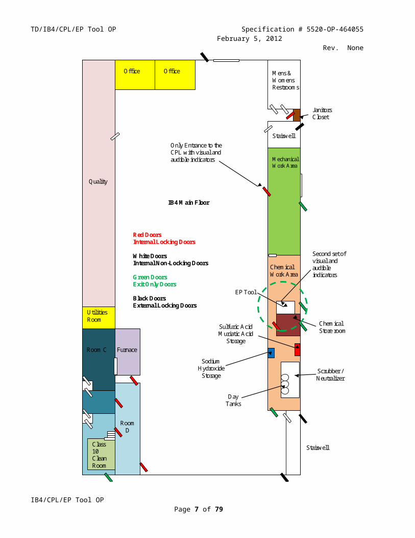
1.2 LocationThe location of the EP Tool within IB4 is shown in Figure 1.2.1.
IB4/CPL/EP Tool OPPage 5 of 59

TD/IB4/CPL/EP Tool OP Specification # 5520-OP-464055February 5, 2012
Rev. None
Room C
Utilities Room
Room D
Mechanical Work Area
Chemical Work Area
Chemical Store room
Furnace
Class 10 Clean Room
Mens & Womens Restrooms
Stairwell
Janitors Closet
Red Doors Internal Locking Doors White Doors Internal Non-Locking Doors Green Doors Exit Only Doors Black Doors External Locking Doors
IB4 Main Floor
Quality
Stairwell
Office Office
Only Entrance to the CPL with visual and audible indicators
Second set of visual and audible indicators
EP Tool
Sulfuric Acid Muriatic Acid
Storage
Sodium Hydroxide
Storage
Day Tanks
Scrubber / Neutralizer
Figure 1.2.1 Location of the EP Tool
IB4/CPL/EP Tool OPPage 6 of 59
TD/IB4/CPL/EP Tool OP Specification # 5520-OP-464055February 5, 2012
Rev. None1.3 Frequency of Occurrence
The EP tool is intended to process one cavity per week. The frequency of electrolyte handling needed to support electropolishing activity is covered in 5520-OP-464051 “IB4/CPL/Electrolyte Handling OP”. It is anticipated that one 30 gallon drum of electrolyte will be received per month and one 30 gallon drum of electrolyte will be shipped away per month.
1.4 Responsibility and AuthorityResponsibility and authority for the IB4/CPL/EP tool rests with the operations person in charge (OPIC). This includes scheduling, Integrated Safety Management (ISM), Integrated Quality Assurance (IQA), and establishment and maintenance of the OP and the operational readiness clearance.
The OPIC will be assisted by an authorized EP Tool Operator (EPTO) for all procedures and will be assisted by authorized chemical workers as required. Additional workers may be present for training during operation of the EP tool.
Responsibility and authorization are covered in more detail in 5520-OP-464050 “IB4/CPL/EP Tool Authorization OP”.
2 Operating Procedure2.1 Equipment
2.1.1 EP ToolThe IB4 CPL EP tool is shown in Figure 2.1.1.1. The tool consists of the EP tool cabinet and the EP tool sled.
Figure 2.1.1.1. IB4 EP Tool2.1.1.1 EP Tool Cabinet
The EP tool cabinet, including the windows, is made of electrolyte resistant PVC plastic. All seams are thermally fused to prevent leaks.
2.1.1.2 EP Tool SledThe EP tool sled is shown in Figure 2.1.1.2.1. The sled can be removed from the cabinet by breaking the appropriate electrical and fluid connections and retracting the sled by means of a rail system. Cabinet doors are closed whenever electrolyte is present.
IB4/CPL/EP Tool OPPage 7 of 59
Hazardous Gas Detectors
Warning and Alarm Lamps
PLCMonitor

TD/IB4/CPL/EP Tool OP Specification # 5520-OP-464055February 5, 2012
Rev. None
Figure 2.1.1.2.1 Electropolish Tool Sled
2.1.1.3 Fluid handling SystemA diagram of the fluid handling system for the EP Tool is shown in Figure 2.1.1.3.1.
IB4/CPL/EP Tool OPPage 8 of 59

TD/IB4/CPL/EP Tool OP Specification # 5520-OP-464055February 5, 2012
Rev. None
Figure 2.1.1.3.1 IB4 EP Tool Fluid Flow Diagram
2.1.1.4 Secondary Containment EquipmentThe EP tool cabinet functions as secondary containment for the EP process. In addition, the EP tool cabinet as well as the entire IB4 chemical storeroom each sit on a large secondary containment vessel. Any electrolyte spills of more than one gallon can be pumped from these vessels into a dedicated electrolyte resistant storage drum located in the chemical storeroom. Any electrolyte spills of one gallon or less, or low pH water spills, can be diluted with water and pumped to the IB4 neutralizer. Control of the pumps is accomplished by an EP tool operator from the EP tool programmable logic controller (PLC) panel. The secondary containment vessel for the EP Tool cabinet is shown in Figure 2.1.1.4.1.
IB4/CPL/EP Tool OPPage 9 of 59

TD/IB4/CPL/EP Tool OP Specification # 5520-OP-464055February 5, 2012
Rev. None
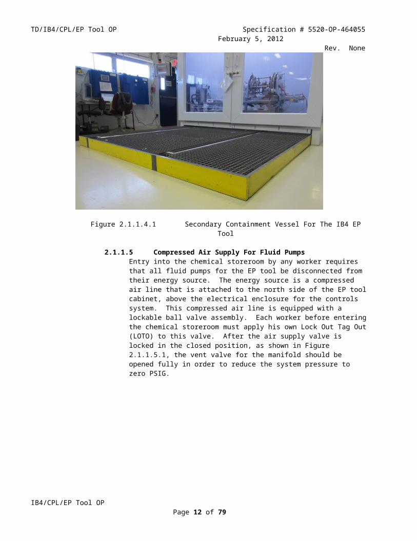
Figure 2.1.1.4.1 Secondary Containment Vessel For The IB4 EP Tool
2.1.1.5 Compressed Air Supply For Fluid PumpsEntry into the chemical storeroom by any worker requires that all fluid pumps for the EP tool be disconnected from their energy source. The energy source is a compressed air line that is attached to the north side of the EP tool cabinet, above the electrical enclosure for the controls system. This compressed air line is equipped with a lockable ball valve assembly. Each worker before entering the chemical storeroom must apply his own Lock Out Tag Out (LOTO) to this valve. After the air supply valve is locked in the closed position, as shown in Figure 2.1.1.5.1, the vent valve for the manifold should be opened fully in order to reduce the system pressure to zero PSIG.
Figure 2.1.1.5.1 LOTO Valve for Fluid Pump Energy Source (Compressed Air)
IB4/CPL/EP Tool OPPage 10 of 59
Manifold Vent Valve
Compressed Air LOTO Valve

TD/IB4/CPL/EP Tool OP Specification # 5520-OP-464055February 5, 2012
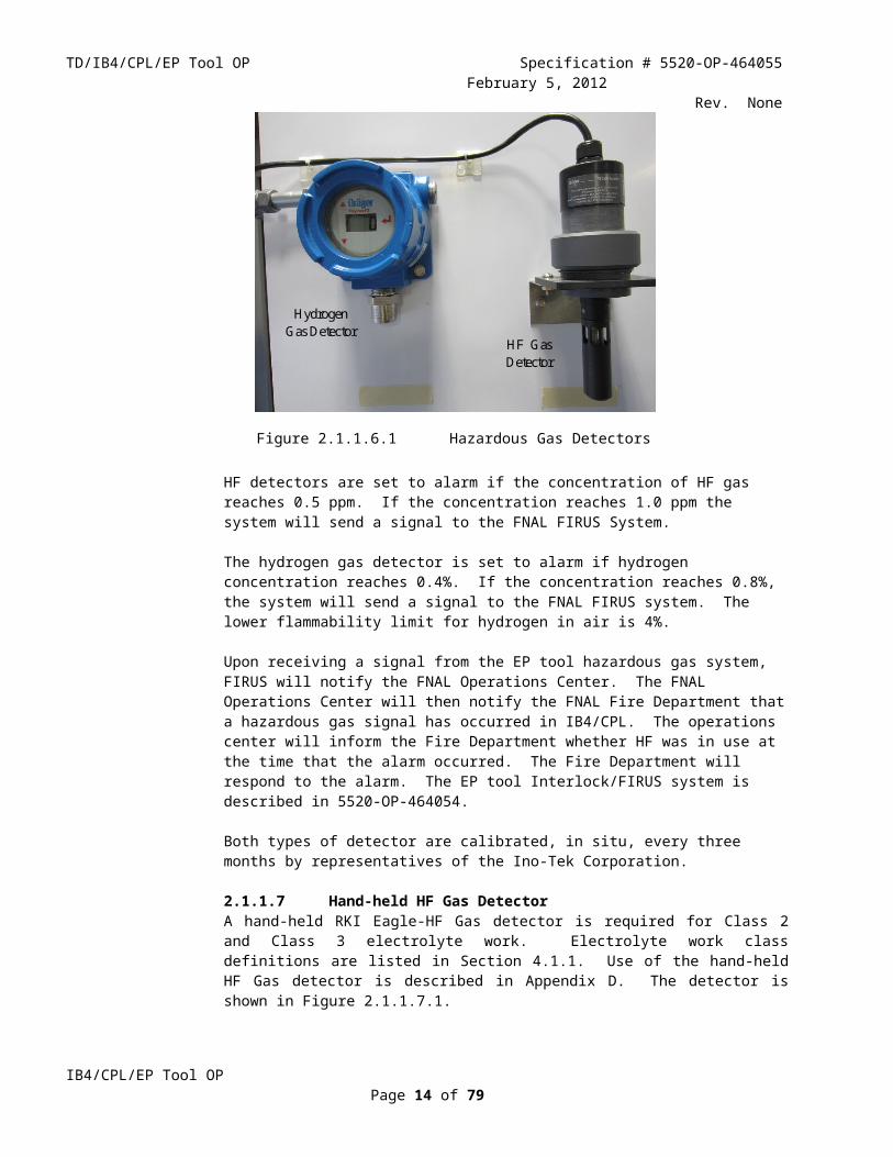
Rev. None2.1.1.6 Hazardous Gas DetectorsHazardous gas detectors are used to protect both people and equipment. Hazardous Gas detectors mounted on the front panel of the EP tool are shown in Figure 2.1.1.6.1. The location of the detectors can be seen in Figure 2.1.1.1. There is also an independent HF detector located near the center point of the ceiling in the IB4/CPL chemical storeroom. All three of these detectors are part of the EP tool Interlock/FIRUS system. The chemical storeroom HF gas detector is described in 5520-OP-464051 “IB4/CPL/Electrolyte Handling OP”.
Hydrogen Gas Detector
HF Gas Detector
Figure 2.1.1.6.1 Hazardous Gas Detectors
HF detectors are set to alarm if the concentration of HF gas reaches 0.5 ppm. If the concentration reaches 1.0 ppm the system will send a signal to the FNAL FIRUS System.
The hydrogen gas detector is set to alarm if hydrogen concentration reaches 0.4%. If the concentration reaches 0.8%, the system will send a signal to the FNAL FIRUS system. The lower flammability limit for hydrogen in air is 4%.
Upon receiving a signal from the EP tool hazardous gas system, FIRUS will notify the FNAL Operations Center. The FNAL Operations Center will then notify the FNAL Fire Department that a hazardous gas signal has occurred in IB4/CPL. The operations center will inform the Fire Department whether HF was in use at the time that the alarm occurred. The Fire Department will respond to the alarm. The EP tool Interlock/FIRUS system is described in 5520-OP-464054.
Both types of detector are calibrated, in situ, every three months by representatives of the Ino-Tek Corporation.
2.1.1.7 Hand-held HF Gas DetectorA hand-held RKI Eagle-HF Gas detector is required for Class 2 and Class 3 electrolyte work. Electrolyte work class definitions are listed in Section 4.1.1. Use of the hand-held HF Gas detector is described in Appendix D. The detector is shown in Figure 2.1.1.7.1.
IB4/CPL/EP Tool OPPage 11 of 59
TD/IB4/CPL/EP Tool OP Specification # 5520-OP-464055February 5, 2012
Rev. None
Figure 2.1.1.7.1 RKI Eagle-HF Portable Hydrogen Fluoride Gas Detector
2.1.1.8 EP Power SupplyThe electrical power used for the EP process is provided by an Agilent 6691A 0-30V/0-220A DC power supply located in a closed relay rack (FRR309 / FCC-2-1458) near the IB4/CPL scrubber. The supply and cabinet are shown in Figure 2.1.1.8.1.
Figure 2.1.1.8.1 EP Tool Power Supply And Relay Cabinet
The EP power supply is controlled only through the EP tool PLC. There are no local controls under normal operation. Whenever work is performed inside the EP tool cabinet, the electrical power cord to the EP power supply must be disconnected and LOTO must be applied by each worker before entering the EP tool cabinet. Please see EP Tool/Chemical Storeroom LOTO OP (TD-512072) appended to this document.
IB4/CPL/EP Tool OPPage 12 of 59
EP power supply located here

TD/IB4/CPL/EP Tool OP Specification # 5520-OP-464055February 5, 2012
Rev. None
2.2 MaterialElectrolyte used for electropolishing niobium is a mixture of 96% ( by weight) sulfuric acid and 49% (by weight) hydrofluoric acid. The ratio of the mixture is by volume 9:1 sulfuric:hydrofluoric. Because of its highly corrosive and chemically poisonous properties, EP electrolyte requires special handling. National Fire Protection Association (NFPA) hazardous material diamonds for electrolyte components are shown in Figure 2.2.1.
Sulfuric Acid Hydrofluoric Acid
Figure 2.2.1 NFPA 704 Designations for Electrolyte Components
Note: NFPA 704 Designations are explained in Appendix C “MSDS”.
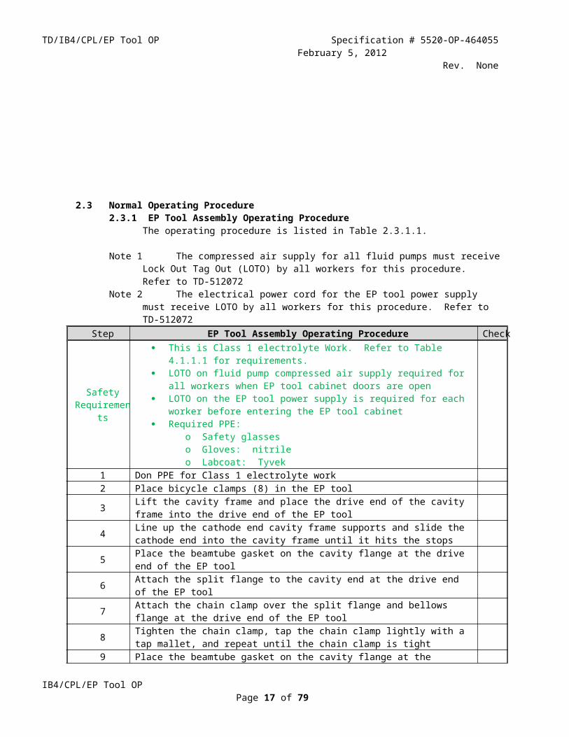
2.3 Normal Operating Procedure2.3.1 EP Tool Assembly Operating Procedure
The operating procedure is listed in Table 2.3.1.1.
Note 1 The compressed air supply for all fluid pumps must receive Lock Out Tag Out (LOTO) by all workers for this procedure. Refer to TD-512072
IB4/CPL/EP Tool OPPage 13 of 59
TD/IB4/CPL/EP Tool OP Specification # 5520-OP-464055February 5, 2012
Rev. NoneNote 2 The electrical power cord for the EP tool power supply must receive LOTO by all workers for
this procedure. Refer to TD-512072Step EP Tool Assembly Operating Procedure Check
Safety Requirements
This is Class 1 electrolyte Work. Refer to Table 4.1.1.1 for requirements. LOTO on fluid pump compressed air supply required for all workers when EP
tool cabinet doors are open LOTO on the EP tool power supply is required for each worker before entering
the EP tool cabinet Required PPE:
o Safety glasseso Gloves: nitrileo Labcoat: Tyvek
1 Don PPE for Class 1 electrolyte work2 Place bicycle clamps (8) in the EP tool
3 Lift the cavity frame and place the drive end of the cavity frame into the drive end of the EP tool
4 Line up the cathode end cavity frame supports and slide the cathode end into the cavity frame until it hits the stops
5 Place the beamtube gasket on the cavity flange at the drive end of the EP tool6 Attach the split flange to the cavity end at the drive end of the EP tool
7 Attach the chain clamp over the split flange and bellows flange at the drive end of the EP tool
8 Tighten the chain clamp, tap the chain clamp lightly with a tap mallet, and repeat until the chain clamp is tight
9 Place the beamtube gasket on the cavity flange at the cathode end of the EP tool10 Attach the split flange to the cavity end at the cathode end of the EP tool
11 Attach the chain clamp over the split flange and bellows flange at the cathode end of the EP tool
12 Tighten chain clamp, tap the chain clamp lightly with a tap mallet, and repeat until the chain clamp is tight
13 Latch bicycle clamps (8) tight14 Slide hold down clamps to the cathode end of the EP tool and tighten them15 Attach the electrical connection braid to the cavity16 Ensure that the cavity frame is free of obstructions17 Push the EP tool frame into the EP Tool cabinet until it hits the stops18 Connect electrolyte lines (2) on the front of the EP tool19 Connect chiller lines (2)20 Connect air and nitrogen lines21 Connect EP current leads at the upper-right rear of the EP tool cabinet22 Connect control cable connectors (2)23 Close the doors of the EP tool cabinet24 Wipe down your PPE with Wypall X80 towels25 Remove LOTO from fluid pump compressed air supply26 Dispose of the used Wypall X80 towels in the trash27 Remove and store PPE
Table 2.3.1.1 EP Tool Assembly Operating Procedure
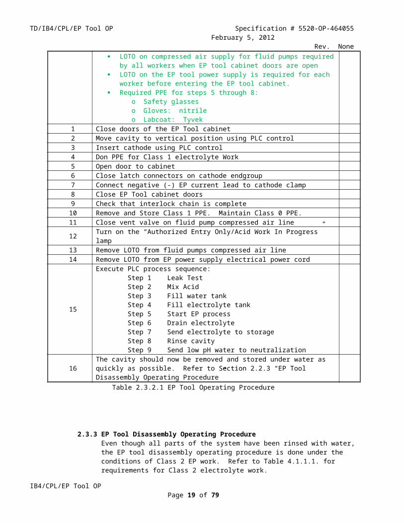
2.3.2 EP Tool Operating ProcedureRefer to Figure 2.1.1.3.1 for component identification and location within the fluid diagram.
Note 1 The compressed air supply for all fluid pumps must receive LOTO by all workers for parts of this procedure. Refer to TD-512072
IB4/CPL/EP Tool OPPage 14 of 59

TD/IB4/CPL/EP Tool OP Specification # 5520-OP-464055February 5, 2012
Rev. NoneNote 2 The electrical power cord for the EP tool power supply must receive LOTO by all workers for
parts of this procedure. Refer to TD-512072
The operating procedure is listed in Table 2.3.2.1.Step EP Tool Operating Procedure Check
Safety Requirements
This is Class 0 electrolyte work with the exception of steps 5 through 8. Steps 5 through 8 are Class 1 electrolyte work. Refer to Table 4.1.1.1 for requirements.
LOTO on compressed air supply for fluid pumps required by all workers when EP tool cabinet doors are open
LOTO on the EP tool power supply is required for each worker before entering the EP tool cabinet.
Required PPE for steps 5 through 8:o Safety glasseso Gloves: nitrileo Labcoat: Tyvek
1 Close doors of the EP Tool cabinet2 Move cavity to vertical position using PLC control3 Insert cathode using PLC control4 Don PPE for Class 1 electrolyte Work5 Open door to cabinet6 Close latch connectors on cathode endgroup7 Connect negative (-) EP current lead to cathode clamp8 Close EP Tool cabinet doors9 Check that interlock chain is complete10 Remove and Store Class 1 PPE. Maintain Class 0 PPE.11 Close vent valve on fluid pump compressed air line12 Turn on the “Authorized Entry Only/Acid Work In Progress” lamp13 Remove LOTO from fluid pumps compressed air line14 Remove LOTO from EP power supply electrical power cord
15
Execute PLC process sequence: Step 1 Leak Test Step 2 Mix Acid Step 3 Fill water tank Step 4 Fill electrolyte tank Step 5 Start EP process Step 6 Drain electrolyte Step 7 Send electrolyte to storage Step 8 Rinse cavity Step 9 Send low pH water to neutralization
16 The cavity should now be removed and stored under water as quickly as possible. Refer to Section 2.2.3 “EP Tool Disassembly Operating Procedure”
2.3.3 EP Tool Disassembly Operating ProcedureEven though all parts of the system have been rinsed with water, the EP tool disassembly operating procedure is done under the conditions of Class 2 EP work. Refer to Table 4.1.1.1. for requirements for Class 2 electrolyte work.
Note 1 The compressed air supply for all fluid pumps must receive LOTO by all workers for this procedure. Refer to TD-512072
Note 2 The electrical power cord for the EP tool power supply must receive LOTO by all workers for this procedure. Refer to TD-512072
IB4/CPL/EP Tool OPPage 15 of 59

TD/IB4/CPL/EP Tool OP Specification # 5520-OP-464055February 5, 2012
Rev. None
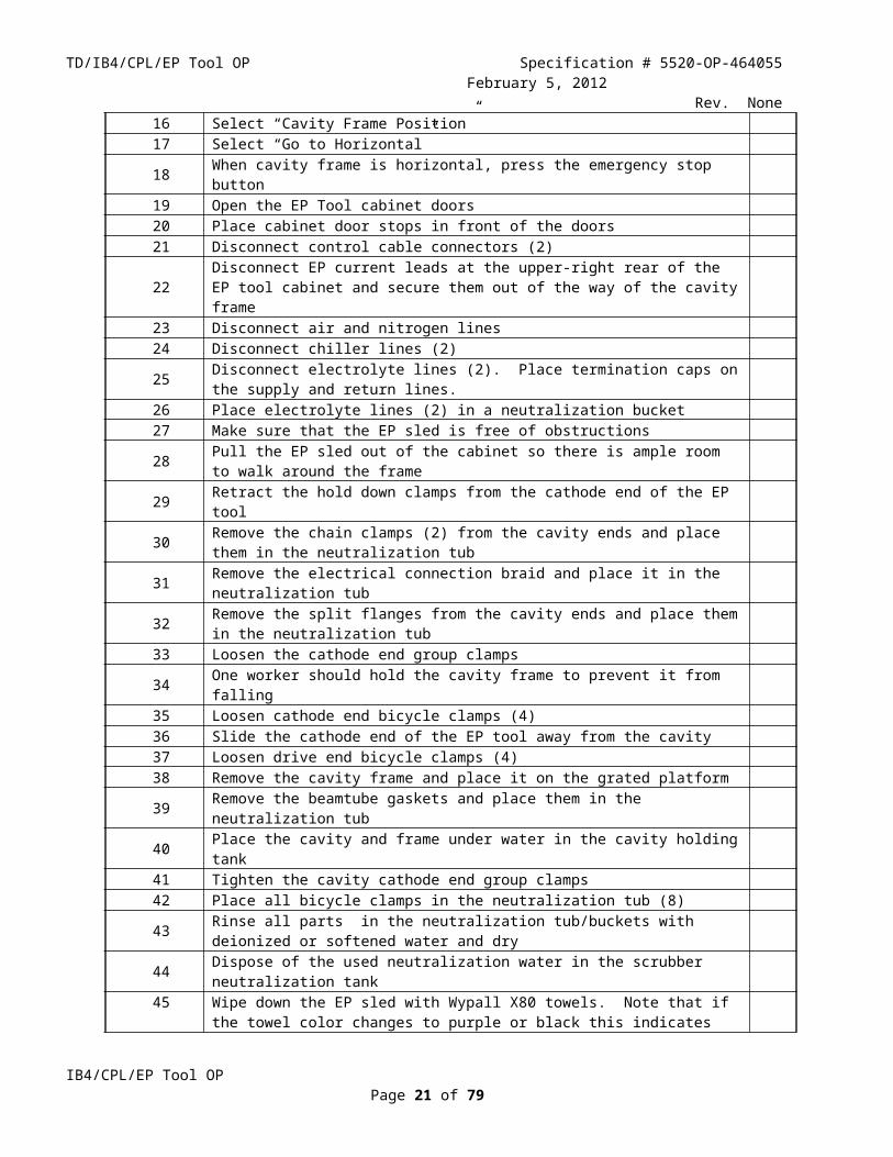
The operating procedure is given in Table 2.3.3.1.
Step EP Tool Disassembly Operating Procedure Check
Safety Requirements
This is Class 2 electrolyte work. Refer to Table 4.1.1.1 for requirements Two Man Rule Is In Effect Test Safety Shower / Eyewash Station (FNAL Communication Center must be
notified prior to test) LOTO on compressed air supply for fluid pumps required by all workers when
EP tool cabinet doors are open LOTO on EP tool power supply is required for each worker before entering the
EP tool cabinet. Required PPE:
o Chemical Splash Goggleso Face Shieldo Gloves: nitrile inner / neoprene outero Jumpsuit: Tychemo Boots: SuperPoly
1 Place the neutralization tub in the sink, fill it with ultra-pure water, and dissolve one cup of sodium bicarbonate in it
2 Fill two buckets with ultra-pure water and dissolve one cup of sodium bicarbonate in each3 Fill the cavity holding tank with ultra-pure water4 Turn on the “Authorized Entry Only/Acid Work In Progress” lamp5 Apply LOTO to energy source for fluid pumps.6 Apply LOTO to EP cathode power supply7 Don PPE for Class 2 electrolyte work8 Open EP Tool cabinet door and sample air with the portable RKI- Eagle, HF Gas Detector9 Enter EP too cabinet only if HF concentration is below 0.5 ppm10 Open end clamps on the Teflon cathode housing11 Ensure that the cavity frame is free of obstructions12 Close the EP Tool cabinet doors13 On the PLC, select “Cavity Frame Position”14 Hold down “Go to Vertical” button15 When cavity frame is vertical, select “Go Home”16 Select “Cavity Frame Position”17 Select “Go to Horizontal”18 When cavity frame is horizontal, press the emergency stop button19 Open the EP Tool cabinet doors20 Place cabinet door stops in front of the doors21 Disconnect control cable connectors (2)
22 Disconnect EP current leads at the upper-right rear of the EP tool cabinet and secure them out of the way of the cavity frame
23 Disconnect air and nitrogen lines24 Disconnect chiller lines (2)25 Disconnect electrolyte lines (2). Place termination caps on the supply and return lines.26 Place electrolyte lines (2) in a neutralization bucket27 Make sure that the EP sled is free of obstructions28 Pull the EP sled out of the cabinet so there is ample room to walk around the frame29 Retract the hold down clamps from the cathode end of the EP tool30 Remove the chain clamps (2) from the cavity ends and place them in the neutralization tub31 Remove the electrical connection braid and place it in the neutralization tub32 Remove the split flanges from the cavity ends and place them in the neutralization tub33 Loosen the cathode end group clamps
IB4/CPL/EP Tool OPPage 16 of 59
TD/IB4/CPL/EP Tool OP Specification # 5520-OP-464055February 5, 2012
Rev. None34 One worker should hold the cavity frame to prevent it from falling35 Loosen cathode end bicycle clamps (4)36 Slide the cathode end of the EP tool away from the cavity37 Loosen drive end bicycle clamps (4)38 Remove the cavity frame and place it on the grated platform39 Remove the beamtube gaskets and place them in the neutralization tub40 Place the cavity and frame under water in the cavity holding tank41 Tighten the cavity cathode end group clamps42 Place all bicycle clamps in the neutralization tub (8)43 Rinse all parts in the neutralization tub/buckets with deionized or softened water and dry44 Dispose of the used neutralization water in the scrubber neutralization tank
45Wipe down the EP sled with Wypall X80 towels. Note that if the towel color changes to purple or black this indicates that the pH is less than 3 and that the area needs to be neutralized with sodium bicarbonate solution.
46 Rinse all containers with deionized or softened water and allow to dry in sink.47 Wipe down PPE with Wypall X80 towels
48Any Wypall towel that indicates a change of color should be neutraliized with sodium bicarbonate solution. Towels that do not indicate low pH and neutralized towels can be disposed of with IB4 building trash.
49 Remove and store PPE50 Turn off the “Authorized Entry Only/Acid Work In Progress” lamp
Table 2.3.3.1 EP Tool Disassembly Operating Procedure
2.3.4 EP Tool Cleanup Note: Refer to 5520-OP-464053 for the operating procedure for the IB4 Scrubber/Neutralizer system.2.3.4.1 Low pH Rinse Water
FESHM 8025 states the following requirements: If wastewater pH is 5.5 pH 9.0, and meets all other discharge criteria, then any
amount can be poured down the drain; If wastewater pH is either 2.0 pH <5.5 or 9.0< pH 12.5, and meets all other discharge
criteria, then a maximum of 50 gallons per day can be poured down the drain.
All rinse water for the EP Tool is pumped to the IB4 neutralizer holding tank for treatment. The pH will meet FESHM 8025 standards before it is released to the IB4 sanitary sewer system.
.2.3.4.2 General
Return HF antidote to the appropriate storage cabinet. Return all containers used to their storage area.
2.3.4.3 Spent ElectrolyteNotify the TD Environmental Officer/Waste Coordinator about the spent electrolyte generated during the EP process. Spent electrolyte should not be stored for more than three months in the IB4 chemical storeroom.
2.3.5 Off Normal EP Process PlanThe plan for dealing with off normal occurrences during an EP process is as follows: If the problem can be investigated and if remedial action can be performed in a way that does not break the integrity of any part of the electrolyte fluid flow path, then it is allowed for work to be performed inside the cabinet doors. Such work will be performed under the conditions of Class 3 Electrolyte work, with all required PPE. An example of this type of off normal condition is the failure of an electrical connection or component, or failure of a non-fluid path mechanical connection or component.
IB4/CPL/EP Tool OPPage 17 of 59

TD/IB4/CPL/EP Tool OP Specification # 5520-OP-464055February 5, 2012
Rev. None
If troubleshooting or remedial action for the problem involves breaking any connections in the electrolyte fluid path, then the plan is to terminate the EP process and complete the remainder of the nine steps in the PLC sequence (Ref. Table 2.3.2.1, Step 11). At the end of these steps electrolyte will have been removed from the EP cabinet and all components in the system will have been rinsed with water. All work performed inside the cabinet will be done under the conditions of Class 2 Electrolyte work, similar to work done in Table 2.3.3.1.
3 Integrated Quality Assurance3.1 Inspection
The interior surface of all cavities processed will be visually inspected before and after each process by the OPIC and the EPTO. Notes on the qualitative condition of the surface will be entered into the EP Process log.
Before electrolyte is introduced into the EP Tool for the first time, the system shall be thoroughly tested using water as the working fluid. Each step in the EP Tool PLC sequence will be verified to function correctly with respect to fluid flow, absence of leaks and mechanical operation.
Before each EP process begins, the EP Tool must pass a leak test with the cavity in place on the tool. The EP tool interlock chain functions as an automated quality assurance system. One example of
this function is the use of proximity sensors that detect the position of the EP tool sled and the EP tool horizontal/vertical positioning system. If these parts of the tool are not in the proper place, the interlock chain is broken and the associated process step will not be allowed to proceed.
3.2 Documentation3.2.1 EP Process Log
A log will be maintained of parameters and conditions for each EP process. Recorded parameters will include the following:
Cavity ID and type Cavity owner/EP process generator Voltage vs. time Current vs. time Cavity wall temperature vs. time Electrolyte sump temperature vs. time Electrolyte flow rate Integral of current vs. time (total charge delivered)
3.2.2 Electrolyte Usage LogA log will be maintained of all the electrolyte used and of all spent electrolyte generated. Results will be reported to the TD Environmental Officer/Waste Coordinator on a weekly basis.
3.2.3 EP ChecklistEP tool checklists are to be followed and completed for every EP operation. These will include the checklists for assembly (Table 2.2.1.1), EP process (Table 2.2.2.1), and disassembly (Table 2.2.3.1).
3.2.4 RecordsHard copies of records will be maintained in the IB4/CPL/EP Tool file cabinet. Electronic copies will be maintained on the local EP tool computer and on the TD:Q drive.
IB4/CPL/EP Tool OPPage 18 of 59
TD/IB4/CPL/EP Tool OP Specification # 5520-OP-464055February 5, 2012
Rev. None
4 Integrated Safety Management4.1 Safety and Health
4.1.1 Electrolyte Work Class DefinitionsIB4 EP Tool electrolyte work class definitions and requirements are listed in Table 4.1.1.1.
IB4/CPL/EP Tool/Chemical Storeroom Electrolyte Work Class Definitions And RequirementsClass Definition Requirements
0
Equipment has been neutralized. There is no possibility for electrolyte contamination
Safety Glasses
1
Equipment has been thoroughly rinsed with water. Risk for electrolyte contamination is low
PPE as per Section 4.1.3
2
Equipment has been exposed to electrolyte. Risk for contamination is present
Water supply: If there is low water pressure or no water then the electrolyte work must be postponed until the eyewash and shower are in working condition.
The “Authorized Entry Only/Acid Work In Progress” warning light must be activated
Two people are required for any electrolyte Class 2 work operation. In case of exposure to electrolyte (or exposure to low pH rinse water) the responsibility of the non-exposed person is to assist the exposed person. Once the person affected is rinsing/showering, the assistant must call 3131 and 3232 to inform emergency personnel and medical of the exposure.
Electrolyte Class 2 work cannot be done without proper training and authorization.
All persons performing Electrolyte class 2 work must have an understanding of the location of the safety shower, eye wash station, HF antidote, phone, PPE and pH strips.
Proper PPE as per Section 4.1.3 All persons performing Electrolyte Class 2 work must have a thorough
understanding of the emergency procedures and must have their own tube of calcium gluconate at home.
Safety signs in the IB4 CPL EP area must be read and understood. Calcium gluconate, must be close to the area where electrolyte is handled.
The expiration date of the calcium gluconate must be verified prior to work. Review where acid absorbent material is kept in case of an acid spill. Review where the safety shower/eye wash station is located. Review where the phone is located.
3
This is work with an open drum of electrolyte. In addition to risk from contact, there is the risk of HF gas inhalation
Class 3 Electrolyte work requires all the precautions of Class 2 Electrolyte work with the additional requirement of a respirator equipped with HF gas filter cartridges for each worker.
All work is continuously monitored with the hand-held HF gas detector. Special attention must be paid to the readout of the hand-held HF gas detector and to the ceiling/wall mounted HF gas detectors.
Table 4.1.1.1 IB4/CPL/EP Tool/Chemical Storeroom Electrolyte Work Class Definitions And Requirements
IB4/CPL/EP Tool OPPage 19 of 59

TD/IB4/CPL/EP Tool OP Specification # 5520-OP-464055February 5, 2012
Rev. None
4.1.2 Training ModulesIB4 EP tool workers must be informed of all applicable FESHM chapters, TD and MDTL safety policies/procedures, and the associated Material Safety Data Sheets (MSDS). The appendices for this document contain reference MSDSs for sulfuric and hydrofluoric acid used in EP electrolyte. In addition, MSDSs can also by found on-line in the Fermilab ES&H, MSDS database1. Applicable FESHM chapters and TD policies include:
FESHM 5051 Hazard Communication FESHM 5100 PPE FESHM 8000 Environmental Protection FESHM 8021 Chemical and Radioactive Waste Management FESHM 8025 Wastewater Discharges to Sanitary Sewers FESHM 8030 Spills and Releases TD Chemical Hygiene Plan (TD-4170)
Note: Hard copies of these documents are kept in the EP tool filing cabinet.
EP tool operators must also fulfill the following requirements: Read and understand hydrofluoric acid first aid instructions Read and understand the HF Emergency Response Procedures OP-333846 Receive authorization according to specification 5520-OP-464050 Complete the Hydrofluoric Acid First Aid training: TD-000003-CR-01 Complete the Fermilab ES&H Hydrofluoric Acid Safety training: FN000404/CR Complete the Chemical Hygiene Plan training: TD505101-MDTL Complete the Hazard Communication training: FN000156 Complete the EP Process at MDTL training (classroom): TD-505102-01-CR Complete the EP Process at MDTL training (on-the-job): TD-505102-01-OJ Complete Safe Handling of SRF Cavities training: FN000434/CR
In order to be qualified to operate the IB4 EP tool each individual shall receive a course of hands-on instruction for all aspects of the various procedures and techniques. Please refer to 5520-OP-464050 “IB 4 CPL EP Tool Authorization OP” for detailed information on qualification procedures.
4.1.3 Personal Protective EquipmentPPE Requirements for Each Work Class are listed in Table 4.1.3.1.
IB4/CPL/EP Tool/Chemical Storeroom Electrolyte Work Class PPE RequirementsClass Requirements
0 Safety glasses1 Nitrile gloves, safety glasses, and a Tyvek lab coat2 Full Electrolyte Work PPE as per Table 4.1.3.23 Full Electrolyte Work PPE as per Table 4.1.3.2 + Respirator
Table 4.1.3.1 IB4/CPL/EP Tool/Chemical Storeroom Electrolyte Work Class PPE Requirements
1 http://www-esh.fnal.gov/owa_user/msds_search.html
IB4/CPL/EP Tool OPPage 20 of 59
TD/IB4/CPL/EP Tool OP Specification # 5520-OP-464055February 5, 2012
Rev. None
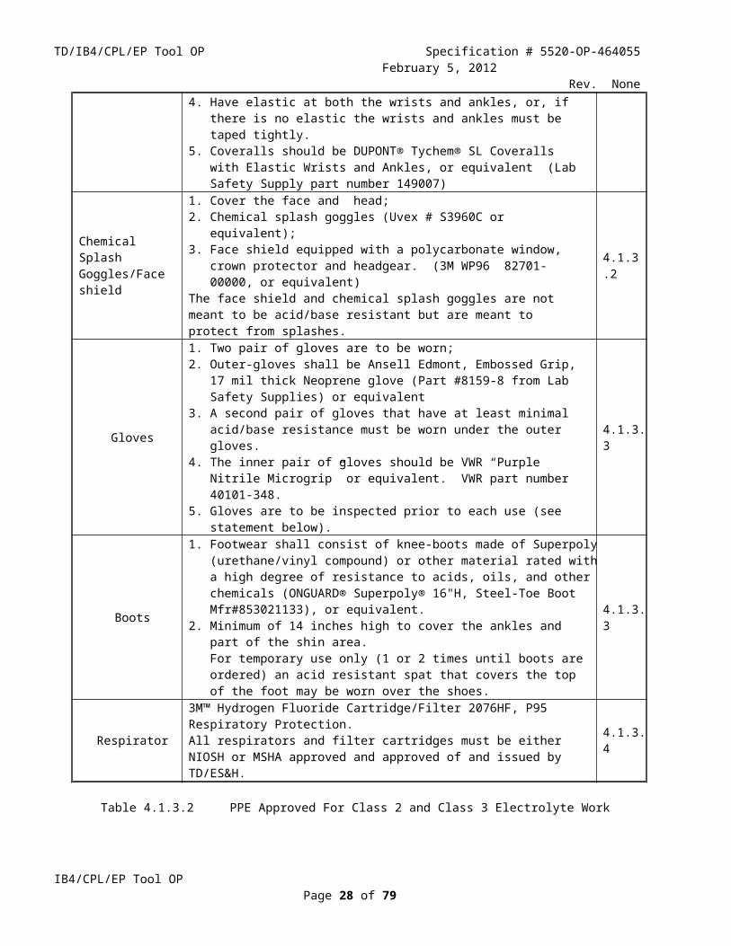
For Class 2 and Class 3 work, protective garments must be worn to cover almost every area where electrolyte could contact a worker. This includes chemical splash goggles, face shield, gloves, boots, and a body suit. The currently approved garments for Class 2 and Class 3 electrolyte work are listed in Table 4.1.3.2.
PPE Approved For Class 2 and Class 3 Electrolyte WorkItem Requirements Figure
Coveralls
1. Cover the body from the neck to the ankles, excluding the hands.2. Acid/Base resistant;3. Made of Tychem or Neoprene4. Have elastic at both the wrists and ankles, or, if there is no elastic the wrists
and ankles must be taped tightly.5. Coveralls should be DUPONT® Tychem® SL Coveralls with Elastic Wrists
and Ankles, or equivalent (Lab Safety Supply part number 149007)
4.1.3.1
Chemical Splash Goggles/Face shield
1. Cover the face and head;2. Chemical splash goggles (Uvex # S3960C or equivalent);3. Face shield equipped with a polycarbonate window, crown protector and
headgear. (3M WP96 82701-00000, or equivalent)The face shield and chemical splash goggles are not meant to be acid/base resistant but are meant to protect from splashes.
4.1.3.2
Gloves
1. Two pair of gloves are to be worn;2. Outer-gloves shall be Ansell Edmont, Embossed Grip, 17 mil thick Neoprene
glove (Part #8159-8 from Lab Safety Supplies) or equivalent3. A second pair of gloves that have at least minimal acid/base resistance must be
worn under the outer gloves.4. The inner pair of gloves should be VWR “Purple Nitrile Microgrip” or
equivalent. VWR part number 40101-348.5. Gloves are to be inspected prior to each use (see statement below).
4.1.3.3
Boots
1. Footwear shall consist of knee-boots made of Superpoly (urethane/vinyl compound) or other material rated with a high degree of resistance to acids, oils, and other chemicals (ONGUARD® Superpoly® 16"H, Steel-Toe Boot Mfr#853021133), or equivalent.
2. Minimum of 14 inches high to cover the ankles and part of the shin area.For temporary use only (1 or 2 times until boots are ordered) an acid resistant spat that covers the top of the foot may be worn over the shoes.
4.1.3.3
Respirator3M™ Hydrogen Fluoride Cartridge/Filter 2076HF, P95 Respiratory Protection.All respirators and filter cartridges must be either NIOSH or MSHA approved and approved of and issued by TD/ES&H.
4.1.3.4
Table 4.1.3.2 PPE Approved For Class 2 and Class 3 Electrolyte Work
The elastic of the coveralls shall cover the gloves up to the wrists and on the ankles it shall cover over the top of the knee-boot down at the ankle. This is to prevent any electrolyte spills from touching the skin.
Gloves shall be inspected for tears or punctures and tested before each use. Each glove shall be tested by inflating with air and then tying off the wrist area and then submerging the glove into a container of standing water. If any air bubbles are detected, dispose of the gloves and test a new pair. New gloves must be inspected and tested before use.
Hydrogen fluoride cartridge filters will be dated when put into service and will be discarded and replaced every six months.
IB4/CPL/EP Tool OPPage 21 of 59

TD/IB4/CPL/EP Tool OP Specification # 5520-OP-464055February 5, 2012
Rev. None
Figure 4.1.3.1 Tychem Jumpsuit With Elastic Cuffs
Figure 4.1.3.2 Face Shield And Chemical Splash Goggles.
IB4/CPL/EP Tool OPPage 22 of 59

TD/IB4/CPL/EP Tool OP Specification # 5520-OP-464055February 5, 2012
Rev. None
Figure 4.1.3.3 Embossed Neoprene Gloves, Yellow Spat & Superpoly Boot
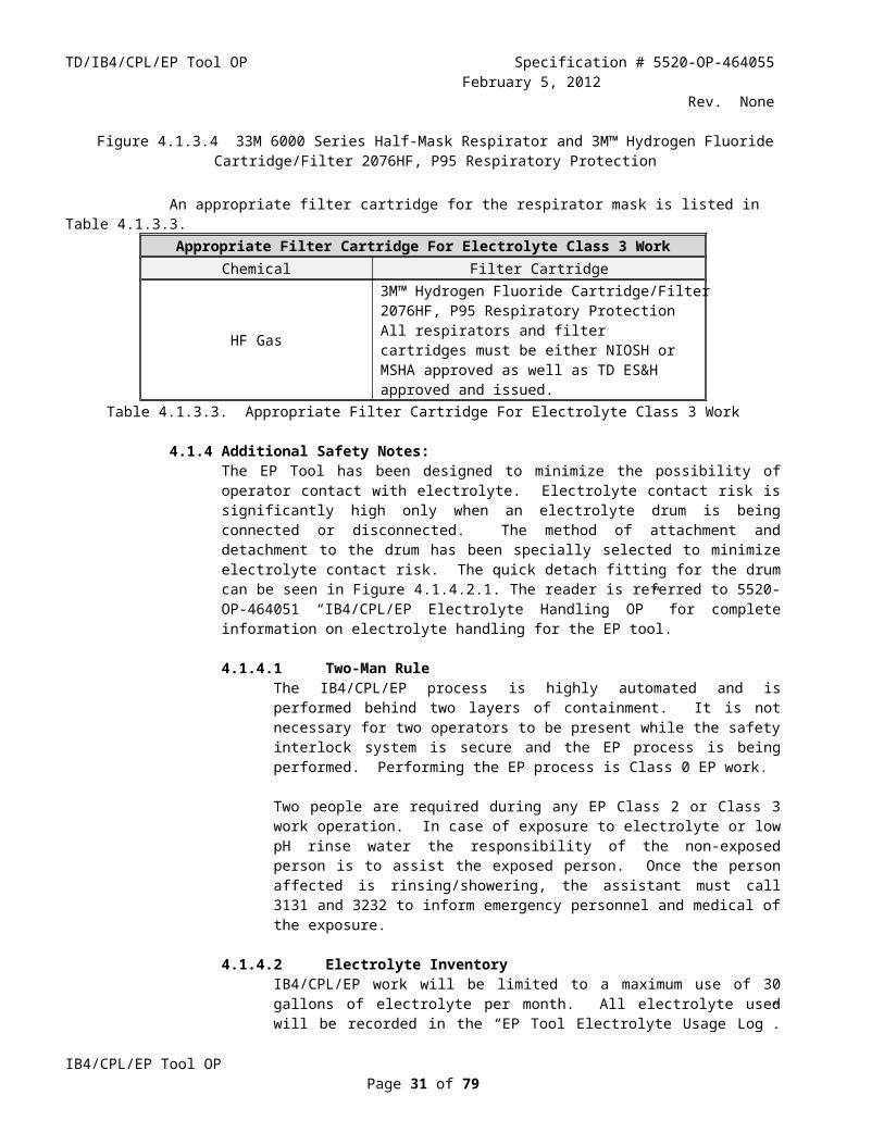
Class 3 work requires a respirator with appropriate filter cartridges. One example of a suitable respirator is shown in Figure 4.1.3.4.
Figure 4.1.3.4 33M 6000 Series Half-Mask Respirator and 3M™ Hydrogen Fluoride Cartridge/Filter 2076HF, P95 Respiratory Protection
An appropriate filter cartridge for the respirator mask is listed in Table 4.1.3.3.Appropriate Filter Cartridge For Electrolyte Class 3 Work
Chemical Filter Cartridge
HF Gas
3M™ Hydrogen Fluoride Cartridge/Filter 2076HF, P95 Respiratory ProtectionAll respirators and filter cartridges must be either NIOSH or MSHA approved as well as TD ES&H approved and issued.
Table 4.1.3.3. Appropriate Filter Cartridge For Electrolyte Class 3 Work
4.1.4 Additional Safety Notes:The EP Tool has been designed to minimize the possibility of operator contact with electrolyte. Electrolyte contact risk is significantly high only when an electrolyte drum is being connected or disconnected. The method of attachment and detachment to the drum has been specially selected to minimize electrolyte contact risk. The quick detach fitting for the drum can be seen in Figure 4.1.4.2.1. The reader is referred to 5520-OP-464051 “IB4/CPL/EP Electrolyte Handling OP” for complete information on electrolyte handling for the EP tool.
IB4/CPL/EP Tool OPPage 23 of 59

TD/IB4/CPL/EP Tool OP Specification # 5520-OP-464055February 5, 2012
Rev. None
4.1.4.1 Two-Man RuleThe IB4/CPL/EP process is highly automated and is performed behind two layers of containment. It is not necessary for two operators to be present while the safety interlock system is secure and the EP process is being performed. Performing the EP process is Class 0 EP work.
Two people are required during any EP Class 2 or Class 3 work operation. In case of exposure to electrolyte or low pH rinse water the responsibility of the non-exposed person is to assist the exposed person. Once the person affected is rinsing/showering, the assistant must call 3131 and 3232 to inform emergency personnel and medical of the exposure.
4.1.4.2 Electrolyte InventoryIB4/CPL/EP work will be limited to a maximum use of 30 gallons of electrolyte per month. All electrolyte used will be recorded in the “EP Tool Electrolyte Usage Log”. A copy of this log will be given to the Environmental Officer/Waste Coordinator for the Technical Division on a weekly basis. The Environmental Officer will serve as a monitor for the amount of electrolyte used in IB4.
Pre-mixed electrolyte is delivered to the IB4/CPL/EP tool chemical storeroom in a PFA plastic lined stainless steel 30 gallon drum. Used electrolyte will be stored in either a 30 gallon or 55 gallon plastic UN/DOT “Class Y” drum that is contained within a plastic UN/DOT “Class X” secondary containment vessel referred to as an “overpack” prior to shipment away from the FNAL site. Drums of electrolyte will be shipped within and will remain within overpacks at all times. An electrolyte supply drum along with its overpack is shown in Figure 4.1.4.2.1
Personnel are only allowed inside the IB4 CPL chemical storeroom when each worker has placed LOTO on the compressed air supply for all fluid pumps. This action prevents operation of any fluid pump while the chemical storeroom is occupied.
Figure 4.1.4.2.1 Electrolyte Supply Drum With Quick Disconnect Fitting In Overpack
IB4/CPL/EP Tool OPPage 24 of 59

TD/IB4/CPL/EP Tool OP Specification # 5520-OP-464055February 5, 2012
Rev. None4.1.4.3 Lock Out Tag Out Requirements
4.1.4.3.1EP Power SupplyA power cord lockout is required for the EP Power Supply whenever workers enter the EP Tool cabinet. Each worker entering the cabinet must apply his own LOTO
4.1.4.3.2Fluid PumpsAll fluid pumps must be disconnected from their energy source whenever:
The EP tool cabinet doors are open, or A worker enters the chemical storeroom
Each worker must apply his own LOTO to the fluid pump compressed air line for these cases.
4.1.4.4 Area ControlPlease see Figure 1.2.1 for a view of the CPL floor plan.
Area control during chemical work is achieved as follows: Restricted Entry: There is only one entry door to the CPL area. This door is always
locked. Only trained and authorized CPL workers have keys to this door. Warnings: There are a set of warning lamps above the entry door to the CPL. Key
holders are trained that only authorized chemical workers are allowed inside the area when the “Authorized Entry Only / Acid Work in Progress” lamp is on.
Further Restricted Entry: Only a subset of key holders are allowed through the doorway between the tumbling area and the chemical work area. The authorized entry list is posted at this doorway.
More Warnings: There is another set of warning lamps located on the EP Tool. These include an “Authorized Entry Only / Acid Work in Progress” lamp that is plainly visible from the doorway between the Tumbling Area and the Chemical Work Area.
A full description of the IB4/CPL area control plan can be found in 5520-OP-464056.
4.1.5 Emergency Response4.1.5.1 Worker Exposure
If at any time during EP tool operations it is believed that electrolyte has come in contact with an unprotected part of a worker, follow the emergency steps listed in Table 4.1.5.1.1
IB4/CPL/EP Tool OPPage 25 of 59

TD/IB4/CPL/EP Tool OP Specification # 5520-OP-464055February 5, 2012
Rev. None
Emergency Response To Electrolyte Contact
Contact Chemical Step Action Check
Skin electrolyte
1 Remove clothing and rinse under safety shower/eyewash. All contaminated clothing must be removed while rinsing with water
2 As soon as the exposure occurs “man number 2” must call 3131 and inform emergency personnel of the exposure
3 A second call must then be made to medical at 3232 to alert the doctor on duty of the exposure and to obtain his advice
4
At the end of five minutes of flushing the area if medical assistance is not on hand to advise, begin applying 2.5% USP calcium gluconate to the affected area. Disposable rubber gloves should be worn during the treatment to eliminate the possibility of receiving a secondary burn. Liberal quantities of calcium gluconate must be massaged into the burned area continuously for up to several hours. Relief of pain is an indicator of the efficiency of the antidote.
Eye electrolyte
1
Flush the eyes and surrounding skin with water. Use the emergency eyewash station. The eye lids should be lifted out so that the water can flush out that area. Continue rinsing the eyes from the time of the exposure until treatment is done at the emergency room.
2 All contaminated clothing must be removed while rinsing with water
3 As soon as the exposure occurs “man number 2” must call 3131 and inform emergency personnel of the exposure
4 A second call must then be made to medical at 3232 to alert the doctor on duty of the exposure and to obtain his advice
5When emergency personnel arrive they must be alerted to the fact that it is an HF exposure to the eyes and that the eyes should be flushed continuously with normal saline solution during transportation to the emergency room
Inhalation
HF gas1 Do not put yourself into a dangerous situation by entering an area that has
elevated levels of HF gas without appropriate training and PPE
2 Portable and wall mounted HF gas detectors should be used to check the HF gas level in the area.
3 If HF concentration is at or above 20.0 ppm:1. Immediately leave the area.2. From a safe location have someone call emergency at 3131.3. A second call must then be made to medical at 3232 to alert the doctor
on duty of the acid exposure and to obtain his advice.4. Attempt to move the victim to a safe place only if you are authorized
for SCBA use.5. Don SCBA and all Electrolyte Class 2 Work PPE. Do not attempt to
assist unless you are qualified to use SCBA.6. Move the exposed worker to a safe location.7. Keep the exposed worker warm and comfortable until help arrives.8. The exposed worker should be administered 100% oxygen as soon as
possible.If HF concentration is at or above 2.0 ppm but below 20 ppm:1. Immediately leave the area.2. From a safe location have someone call emergency at 3131.3. A second call must then be made to medical at 3232 to alert the doctor
on duty of the acid exposure and to obtain his advice.4. Attempt to move the victim to a safe place only if you are authorized
for HF respirator mask or SCBA use. Use only a device that your are
IB4/CPL/EP Tool OPPage 26 of 59

TD/IB4/CPL/EP Tool OP Specification # 5520-OP-464055February 5, 2012
Rev. Nonequalified to use. Use the device that will make assistance available to the injured worker in the shortest amount of time.
5. Don HF respirator mask or SCBA and all Electrolyte Class 2 Work PPE.
6. Move the exposed worker to a safe location.7. Keep the exposed worker warm and comfortable until help arrives.8. The exposed worker should be administered 100% oxygen as soon as
possible.If HF concentration is below 2.0 ppm:1. Don Electrolyte Class 2 work PPE.2. Immediately move the victim to fresh air. Minimize the amount of time
that you are working in the area of elevated HF concentration.3. From a safe location have someone call emergency at 3131.4. A second call must then be made to medical at 3232 to alert the doctor
on duty of the acid exposure and to obtain his advice.5. Keep the exposed worker warm and comfortable until help arrives.6. The exposed worker should be administered 100% oxygen as soon as
possible.Notes:1. The guidelines above are based on a 2.0 ppm HF TLV-C (Threshold
Limit Value-Ceiling) recommendation by the American Conference of Governmental Industrial Hygienists.
2. The use of an HF respirator cartridge increases the maximum exposure limit by a factor of 10
Ingestion electrolyte
1Have the exposed worker drink 1-2 glasses of water as quickly as possible to dilute the acid. Do not induce vomiting. Do not give baking soda. Never give anything by mouth to an unconscious person
2Give several glasses of milk or several ounces of milk of magnesia, Mylanta, Maalox, or grind up and administer up to 30 Tums, Caltrate or other antacid tablets with water
3 As soon as the exposure occurs “man number 2” must call 3131 to notify emergency personnel of the exposure
4 A second call must then be made to medical at 3232 to alert the doctor on duty of the acid exposure and to obtain his advice
5 Keep the exposed worker warm and comfortable until the emergency response team arrives
Table 4.1.5.1.1 Emergency Response To Electrolyte Contact
The physician on duty at FNAL medical may advise transportation to the local emergency room or he may suggest treatment at Fermilab’s medical facility. The contaminated person always has the option of being treated at an emergency medical facility.
Any contaminated clothing must be carefully collected by someone wearing the same PPE as worn by the electrolyte worker. The clothing should then be put into a heavy plastic bag. The bag must then be labeled as being contaminated by hydrofluoric acid/ EP solution. The CPL waste generator should be notified for disposal.
4.1.5.2 HF Gas Alarm Without Worker Exposure
IB4/CPL/EP Tool OPPage 27 of 59
TD/IB4/CPL/EP Tool OP Specification # 5520-OP-464055February 5, 2012
Rev. NoneEP tool HF gas detectors have two alarm levels. At an HF concentration of 0.5%, an alarm will sound and notification will appear on the EP Tool PLC screen. At an HF concentration of 1%, a signal will be sent through the FIRUS system to FNAL operations. FNAL operations will call the FNAL Fire Department and inform them of the hazardous gas alarm.
The response to a hazardous gas alarm without worker exposure is listed in Table 4.1.5.2.1.
Response To Hazardous Gas Alarm Without Worker ExposureConcentration Step Action Check
HF < 1.0ppm1
Work to identify and mitigate the source of the HF gas. Total duration spent in the HF gas environment is not to exceed 60 minutes (see also the emergency response procedures document OP-333846)
2 If the HF gas level remains below 1.0 ppm, it is not necessary to evacuate the IB4 EP Tool area or to call FNAL emergency or medical
HF ≥ 1.0ppm
1 Call 3131 and inform them of the conditions under which the alarm occurred
2 Work with the FNAL Fire Department Incident Commander to determine the reason for the alarm and the best response plan
3 The FNAL Fire Department Incident Commander will decide what, if any, evacuation measures are required
4
The CPL Electrolyte work team should be prepared to provide assistance to the FNAL Fire Department including:1. An SCBA qualified HF worker with Electrolyte Class 3 PPE2. An HF respirator qualified worker with an appropriate respirator for HF gas3. A hand-held HF gas detector4. A qualified EP Tool operator
Table 4.1.5.2.1 Response To Hazardous Gas Alarm Without Worker Exposure
4.1.5.3 General Emergency Shutdown ProcedureWhile the EP process is active, if electrical power is lost, a tornado warning occurs, or a fire alarm occurs, an appropriate emergency response is required and the EP process must be stopped.
4.1.5.3.1 Loss of Electrical PowerIf electrical power is lost, the process will automatically shut down in a safe mode. The process will not resume without a manual reset of the system when electrical power returns.
4.1.5.3.2 Tornado / Fire Alarm / Emergency WarningIf a tornado warning or fire alarm should occur, then use the PLC control to:1 Turn power supply off2 Turn off all liquid pumps3 Allow cavity to continue to rotate4 Respond as required to the tornado warning or fire alarm5 Wait until the tornado warning or fire alarm are cleared before resuming
the EP process6 Turn on liquid pumps7 Wait for system to stabilize8 Turn on power supply
4.2 Environment
IB4/CPL/EP Tool OPPage 28 of 59

TD/IB4/CPL/EP Tool OP Specification # 5520-OP-464055February 5, 2012
Rev. None4.2.1 Waste Generated
Waste materials generated during a normal single-cell 1.3 GHz cavity EP process, and the way that they are handled, are listed in table 4.2.1.1.
IB4 EP Tool Waste Material Management
Waste Quantity Disposal
Spent electrolyte Up to 27 liters
Labeled as Hazardous Waste per FESHM 8021; paperwork filled out; FNAL ES&H Hazard Control Technology Team notified
for disposal.
Low pH rinse water 200 gallonsHandled by IB4/CPL Neutralizer. Sent to
sanitary sewer by Illinois Class “K” wastewater operator after pH test acceptance.
HF gas (Note 1) << the amount of HF in 2.7 liters of 49% hydrofluoric acid
Handled by IB4/CPL Air Scrubber. Neutralized before release to atmosphere.
Hydrogen gas (Note 2) < 1 Liter per minute at STPDiluted to much less than the lower
flammability limit for hydrogen gas before release through the scrubber exhaust.
WypAll X80 towels 25 pcs. Neutralized with sodium bicarbonate. Disposed of in IB4 solid waste.
Sodium bicarbonate < 1 pound2.5% solution used to neutralize tools,
components and disposable towels. Sent to sanitary sewer after pH test acceptance.
Table 4.2.1.1 Waste Material Management
Note (1) 2.7 liters of HF in liquid solution is gross overestimate for HF gas production. It assumes that 100% of the HF in 30 liters of electrolyte is converted to gas. This is, of course, not really the case. Most of the HF either provides fluorine that combines with niobium during the EP process and remains suspended in the spent electrolyte or it remains as unused HF in the spent electrolyte. Only a small fraction of the HF evaporates into the gas phase. Nonetheless, the scrubber is so oversized that it can neutralize 100% of the HF in 30 liters of electrolyte.
Note (2) Calculations for hydrogen gas generation are shown in Appendix D of this document.
4.2.1.1 Liquid WasteNiobium electropolishing produces a compound of niobium and fluorine according to Equation 4.2.1.1.1.(Equation 4.2.1.1.1) 2Nb + 10HF + 2H2O = 2H2NbOF5 + 5H2
The H2NbOF5 will be suspended in the waste electrolyte in the form of oxyfluoroniobic acid. It will be shipped away from FNAL for neutralization and disposal and therefore will not be included in any wastewater discharge at FNAL. After a maximal EP process, up to 200 grams of niobium will be contained in 27 liters of spent electrolyte.
Up to a maximum amount of one liter of electrolyte could be contained in the EP tool rinse water. This is due to the less than on hundred percent efficiency for the equipment draining process after an EP procedure. The usual amount of dissolved electrolyte is expected to be less than 500 ml. One liter of electrolyte dissolved could contain up to 7.4 grams of niobium in the form of H2NbOF5. This equates to a total weight of 16.4 grams of H2NbOF5, resulting in a
IB4/CPL/EP Tool OPPage 29 of 59

TD/IB4/CPL/EP Tool OP Specification # 5520-OP-464055February 5, 2012
Rev. Noneconcentration of approximately 14.4 mg/l of H2NbOF5 for a total neutralizer discharge of 300 gallons to the IB4 sanitary sewer.
The hydrogen fluoride component of EP tool rinse water is handled by the CPL scrubber/neutralizer according to Equation 4.2.1.1.2:(Equation 4.2.1.1.2) HF +NaOH = NaF + H2O
The sulfuric acid component of EP tool rinse water is handled by the CPL scrubber/neutralizer according to Equation 4.2.1.1.3:(Equation 4.2.1.1.3) H2SO4+2NaOH = Na2SO4+2H2O
An EP process that requires one liter of dilute electrolyte to be neutralized will produce 126 grams of NaF and 2,400 grams of Na2SO4. This results in a concentration of 111 mg/l for sodium fluoride and 2,113 mg/l for sodium sulfate for a total neutralizer discharge of 300 gallons. Calculations for waste quantities are presented in the appendix of the operating procedure for the scrubber/neutralizer (5520-OP-464053).
4.2.1.2 Gaseous WasteThe CPL scrubber neutralizes HF gas contained in the EP tool exhaust according to Equation 4.2.1.1.2. Any aerosolized sulfuric acid contained in the EP tool exhaust will be neutralized in the scrubber according to Equation 4.2.1.1.3. The efficiency for neutralization on the scrubber is greater than 95%.
The small amount of sodium fluoride and sodium sulfate that results from exhaust gas neutralization leaves the scrubber through its production of “blowdown” (waste sodium hydroxide solution) and leaves IB4 with neutralized rinse water from the EP tool. These represent negligible additional quantities of waste to EP tool rinse water neutralization.
4.2.1.3 Illinois Environmental Protection Agency Operating Permit for Air QualityLifetime operating permit # 79070012 of 5/8/09 has quantitative limits only for release of nitrogen oxides and particulate matter. Neither of these species are produced by the EP tool or the scrubber/neutralizer. The permit limits the use of the EP tool to less than 5,000 hours per year. The maximum anticipated use is 500 hours per year.
4.2.1.4 Illinois Environmental Protection Agency Operating Permit for Water QualityThe numbers for waste water discharge from section 4.2.1.1 are more than a factor of seven lower than estimates for fluoride and sulfates submitted to the Illinois EPA with the FNAL application for the CPL wastewater operating permit. Fluorides and sulfates are the only relevant species listed in the Illinois EPA requirement. An excerpt from the FNAL permit application (Schedule N Waste Characteristics) is appended to this document.
CPL Neutralizer Liquid Waste DischargeSpecies IL EPA Limit [mg/l] av/max CPL Neutralizer Discharge [mg/l] av/max
H2NbOF5 n/a 7.2 / 14.4
Fluoride 3,620 / 5,480 56 / 111
Sulfate 7,900 / 15,800 1,057 / 2,113
Table 4.2.1.2.1 CPL Neutralizer Liquid Waste Discharge
4.2.2 Controls
IB4/CPL/EP Tool OPPage 30 of 59
TD/IB4/CPL/EP Tool OP Specification # 5520-OP-464055February 5, 2012
Rev. NoneThe potential release of electrolyte, dilute electrolyte, or HF gas are risks to the environment from operation of the IB4/CPL/EP tool. In order to minimize these risks specialized subsystems have been integrated into the design of the EP Tool.
Two of these subsystems are described in a separate document, 5520-OP-464053, “IB4/CPL/Scrubber/Neutralizer Operating Procedure”. The scrubber and neutralizer are used to treat waste products so that they are within Federal EPA, Illinois state and local environmental guidelines before they are released from IB4. Please refer to the scrubber/neutralizer OP for further details.
The third subsystem is the secondary containment vessel system. Its purpose is to ensure that no fluids are released into the IB4 CPL. The secondary containment system is described in Section 2.1.1.4 of this document. Please refer to that section for further details.
The attitude for operation of the EP Tool is that the most effective way to handle release of electrolyte is by prevention of any release. To this end, the EP Tool has been designed to minimize the probability for even small leaks, including the incorporation of Entegris Flare-Tek fittings for all electrolyte piping. In addition, each time a cavity is to be electropolished, the system undergoes a thorough leak check, with the cavity in place, before the EP process can begin. The leak check is part of the PLC Step list (Section 2.2.2.1 of this document).
4.2.3 Response to Off Normal OccurrenceThe proper response to any off normal occurrence is to stop the EP process and take corrective actions.
The IB4/CPL/EP Tool has an integrated Safety Interlock System that is designed to handle most off normal circumstances. This Safety Interlock System is described in a separate document, 5520-OP-464054, “IB4/CPL/EP Tool Interlock/FIRUS Safety System OP”. Please refer to that document for further details.
When a manual emergency shutdown of the system is required, the operator should activate (push) one of the two Emergency Stop Switches. Emergency Stop Switches are shown in Figure 4.2.3.1.
Emergency Shut Down Switch
Figure 4.2.3.1. Emergency Shutdown SwitchAppendix A List of Authorized Workers
IB4/CPL/EP Tool OPPage 31 of 59

TD/IB4/CPL/EP Tool OP Specification # 5520-OP-464055February 5, 2012
Rev. None
A list of authorized workers per 5520-OP-464050 is maintained by TD headquarters and the TD/SMD Head. All workers authorized for CPL electrolyte handling will sign the Hazard Analysis Form in Appendix B of this document.
Appendix B FNAL Hazard Analysis Form
Hazard Analysis FormHazard Analysis Form Revised 11/08
This form can be used by Fermilab Employees, Fermilab Supervisors, Fermilab Task Managers, Construction Coordinators, Service Coordinators and Fermilab Subcontractors. This is a dynamic document which may require modification as the project moves from start to finish and should be readily available at the site where the work is being performed. Note: Not all sections of the first page are applicable to every job or task, complete what is necessary for your specific job or task.
Job Title Operation of the IB4/CPL/EP Tool
Job Location IB4 / CPL
Contract/Work Order # Not ApplicableTO BE COMPLETED FOR WORK INVOLVING SUBCONTRACTORS
Subcontractor (if applicable) FermilabCompany Project Eng/C.M. Project Manager PhonePhone TM/CC/SC ESH Rep. Phone Page Phone Page ES&H Rep.
Phone Page
AT LEAST TWO SIGNATURES ARE REQUIRED
Prepared Date 5jan12
Print Name Anthony Crawford
Accepted Date
Print Name
Accepted as noted Date
Print Name
Description of Work: Operation of the IB4/CPL/EP Tool.
Personal Protective Equipment: (Check protective equipment required for the job.)
IB4/CPL/EP Tool OPPage 32 of 59

TD/IB4/CPL/EP Tool OP Specification # 5520-OP-464055February 5, 2012
Rev. None
□ Safety glasses □ Side shields □ X Chemical splash goggles□ Hearing Protection □ Hard Hats□ 3.0 Brazing goggles □ Impact goggles□ X Face shield □ Rubber apron□ Leather gloves □ Hot/Cold thermal protective gloves□ X Chemical resistant gloves (specify type): □ Respirators Neoprene + Nitrile □ Other required PPE (specify): □ Fall protection equipment (specify):Tychem jumpsuit;inner gloves(nitrile);Chemical resistant rubber boots
Environmental Aspects (check one): □ X Yes, I have thought about the environmental aspects of this job and will document such aspects and mitigation steps
within this document.
□ Yes, I have thought about the environmental aspects of this job and no such credible aspects exist and therefore do not need to be written in this document.
Equipment required for the job: (List the tools needed to perform the job.)
WypAll X80 towels; Nitrile gloves (disposable); PPE; Various Hand ToolsWork Plan History Information: (List any lessons learned incidents from this job, tips from previous jobs)The operation of the IB4/CPL/EP Tool is based on experience, lessons learned, and feedback from similar operations at other laboratories, including JLab, DESY, and ANL. Lessons learned from these facilities have been incorporated into the design and operational Plan for the IB4/CPL/EP Tool.
Improvement/Feedback: At the conclusion of the job, the Task Manager, Supervisor and/or Project Leader shall work with those involved to consider lessons learned and receive feedback in order to improve future work plans.
Check One:□ XYes we have considered lessons learned and accepted feedback on this job and will communicate such information so
that future work plans may be improved. □ Yes we have considered lessons learned feedback and determined that future work plans do not need to be improved.
Hazard Analysis Form Revised 11/08
IB4/CPL/EP Tool OPPage 33 of 59

TD/IB4/CPL/EP Tool OP Specification # 5520-OP-464055February 5, 2012
Rev. NoneUtilizing the format below, identify hazards and environmental aspects, and their corresponding safety precautions/procedures to mitigate hazards. Use as many sheets as necessary.
HAZARD ANALYSIS Hazard Analysis Form Revised 11/08Step Description Hazards/
Environmental AspectsPrecautions / Safety Procedures
1 Receive electrolyte with damaged container
Operator contact/Equipment or Environmental damage
Operator training +authorization+Inspection by qualified operators wearing PPE before acceptance of shipmentReference: 5520-OP-464051“IB4/CPL/EP Electrolyte Handling OP”
2 Spill of electrolyte at IB4/CPL
Operator contact/Equipment or Environmental damage
Operator training +authorization+PPE+ Secondary containmentReference: 5520-OP-464051“IB4/CPL/EP Electrolyte Handling OP”
3Chemical leak while stored at IB4/CPL
Operator contact/Equipment or Environmental damage
Operator training + authorization +PPE+Specialized storage facility+Regular inspection+Secondary containmentReference: 5520-OP-464051“IB4/CPL/EP Electrolyte Handling OP”
4 Chemical spill attaching/detaching fresh electrolyte drum
Operator contact/Equipment or Environmental damage
Operator training + authorization +PPE+Secondary containmentReference: 5520-OP-464051“IB4/CPL/EP Electrolyte Handling OP”
5 Chemical spill attaching/detaching spent electrolyte drum
Operator contact/ Environmental damage
Operator training + authorization +PPE+Secondary containmentReference: 5520-OP-464051“IB4/CPL/EP Electrolyte Handling OP”
7Leak of diluted electrolyte solution
Operator contact/Equipment or Environmental damage
Operator training + authorization +PPE+Secondary containmentReference: 5520-OP-464053“IB4/CPL/Scrubber/Neutralizer OP”
8 Operator contact with low pH water during cavity detachment
Operator contact Operator training + authorization +PPE+ Emergency Response PlanReference: 5520-OP-464051“IB4/CPL/EP Electrolyte Handling OP”
9 HF Gas Evolution Inhalation/ Environmental damage EP Tool Cabinet ventilation to Scrubber/Neutralizer+HF gas detector+Interlock/FIRUS SystemReference: 5520-OP-464054“IB4/CPL/EP Tool Interlock/FIRUS OP”
10 Hydrogen Gas Evolution
Fire EP Tool Cabinet ventilation to Scrubber/Neutralizer+Hydrogen gas detector+Interlock/FIRUS SystemReference: 5520-OP-464054“IB4/CPL/EP Tool Interlock/FIRUS OP”
11 EP Power Supply (HP 30V-220A DC)
Spark/Heat Generation Operation manual from manufacturer. Basic Electrical training for operator. Unit is internally protected for over current and over temperature conditions. All leads and connectors rated at 600V/220A, continuous duty; Leads insulated; Connections insulated and verified in good condition before turning on the power supply.Power Supply locked out before worker enters EP Tool cabinet.
12 Cavity Handling Damage to cavity/Injury to worker TD cavity handling training (FN000434/CR)+ PPE
IB4/CPL/EP Tool OPPage 34 of 59

TD/IB4/CPL/EP Tool OP Specification # 5520-OP-464055February 5, 2012
Rev. None
GUIDELINES FOR COMPLETING THE HAZARD ANALYSIS
Phase of Work Safety Hazard Precautions/Safety ProceduresExamining a specific job by breaking it down into a series of steps or tasks, will enable you to discover potential hazards employees may encounter.
Each job or operation will consist of a set of steps or tasks. For example, the job might be to move a box from a conveyor in the receiving area to a shelf in the storage area. To determine where a step begins or ends, look for a change of activity, change in direction or movement.
Picking up the box from the conveyor and placing it on a hand truck is one step. The next step might be to push the loaded hand truck to the storage area (a change in activity. Moving the boxes from the truck and placing them on the shelf is another step. The final step might be returning the hand truck to the receiving area.
Be sure to list all steps needed to perform the job. Some steps may not be performed each time; an example could be checking the casters on the hand truck. However, if that step is generally part of the job it should be listed.
A hazard is a potential danger to a person or equipment. The purpose of the Job Safety Analysis is to identify ALL hazards- both those produced by the environment and those connected with the job procedure.
To identify hazards, ask yourself these questions about each step:
Is there a danger of the employee striking against, being struck by, or otherwise making injurious contact with an object?
Can the employee be caught in, by, or between objects?
Is there potential for slipping, tripping, or falling?
Could the employee suffer strains from pushing, pulling, lifting, bending, or twisting?
Is the environment hazardous to safety and/or health (toxic gas, vapor, mist, fumes, dust, heat, or radiation)?
Are there electrocution hazards?
Close observation and knowledge of the job is important. Examine each step carefully to find and identify hazards- the actions, conditions, and possibilities that could lead to an accident. Compiling an accurate and complete list of potential hazards will allow you to develop the recommended safe job procedures needed to prevent accidents.
Using the first two columns as a guide, decide what actions or procedures are necessary to eliminate or minimize the hazards that could lead to an accident, injury, or occupational illness.
Begin by trying to: 1) engineer the hazard out; 2) provide guards, safety devices, etc.; 3) provide personal protective equipment; 4) provide job instruction training; 5) maintain good housekeeping; 6) insure good ergonomics (positioning the person in relation to the machine or other elements in such a way as to improve safety).
List the recommended safe operating procedures. Begin with an action word. Say exactly what needs to be done to correct the hazard, such as, “lift using your leg muscles.” Avoid general statements such as, “be careful”, “use caution”, and “be alert”.
List the required or recommended personal protective equipment necessary to perform each step of the job.
Give a recommended action or procedure for each hazard.
Serious hazards should be corrected immediately. The JSA should then be changed to reflect the new conditions.
Finally, review your input on all three columns for accuracy and completeness. Determine if the recommended actions or procedures have been put in place. Re-evaluate the job safety analysis as necessary.
Hazard Analysis Form Revised 11/08
IB4/CPL/EP Tool OPPage 35 of 59

TD/IB4/CPL/EP Tool OP Specification # 5520-OP-464055February 5, 2012
Rev. NoneI have reviewed this hazard analysis and I understand the hazards and required precautionary actions. I will follow the requirements of this hazard analysis or notify my supervisor or Fermilab contact if I am unable to do so.
Name and ID (please print) Signature Date
Hazard Analysis Form Revised 11/08
IB4/CPL/EP Tool OPPage 36 of 59

TD/IB4/CPL/EP Tool OP Specification # 5520-OP-464055February 5, 2012
Rev. None
Appendix C MSDS
IB4/CPL/EP Tool OPPage 37 of 59

TD/IB4/CPL/EP Tool OP Specification # 5520-OP-464055February 5, 2012
Rev. None
Appendix C.1 MSDS Hydrofluoric Acid
MSDS Number: H3994 * * * * * Effective Date: 08/18/05 * * * * * Supersedes: 07/07/04
HYDROFLUORIC ACID1. Product IdentificationSynonyms: Fluorohydric acid; fluoric acid; Hydrogen fluoride solution CAS No.: 7664-39-3 Molecular Weight: 20.01 Chemical Formula: HF in Aqueous Solution. Product Codes: J.T. Baker: 5368, 5659, 5818, 5823, 5824, 5840, 5865, 6904, 9559, 9560, 9563, 9564, 9567, 9572, 9573, 9574, 9575 Mallinckrodt: 2640, 2648, V141, V580
2. Composition/Information on Ingredients
Ingredient CAS No Percent Hazardous ----------------------------------- ------------ ------------ --------- Hydrogen Fluoride 7664-39-3 48 - 52% Yes Water 7732-18-5 48 - 52% No
3. Hazards IdentificationEmergency Overview -------------------------- POISON! DANGER! CORROSIVE. EXTREMELY HAZARDOUS LIQUID AND VAPOR. CAUSES SEVERE BURNS WHICH MAY NOT BE IMMEDIATELY PAINFUL OR VISIBLE. MAY BE FATAL IF SWALLOWED OR INHALED. LIQUID AND VAPOR CAN BURN SKIN, EYES AND RESPIRATORY TRACT. CAUSES BONE DAMAGE. REACTION WITH CERTAIN METALS GENERATES FLAMMABLE AND POTENTIALLY EXPLOSIVE HYDROGEN GAS.
SAF-T-DATA(tm) Ratings (Provided here for your convenience) ----------------------------------------------------------------------------------------------------------- Health Rating: 4 - Extreme (Poison) Flammability Rating: 0 - None Reactivity Rating: 2 - Moderate Contact Rating: 4 - Extreme (Corrosive)
IB4/CPL/EP Tool OPPage 38 of 59

TD/IB4/CPL/EP Tool OP Specification # 5520-OP-464055February 5, 2012
Rev. NoneLab Protective Equip: GOGGLES & SHIELD; LAB COAT & APRON; VENT HOOD; PROPER GLOVES Storage Color Code: White (Corrosive) -----------------------------------------------------------------------------------------------------------
Potential Health Effects ---------------------------------- Exposure to hydrofluoric acid can produce harmful health effects that may not be immediately apparent. Inhalation: Severely corrosive to the respiratory tract. May cause sore throat, coughing, labored breathing and lung congestion/inflammation. Ingestion: Corrosive. May cause sore throat, abdominal pain, diarrhea, vomiting, severe burns of the digestive tract, and kidney dysfunction. Skin Contact: Corrosive to the skin. Skin contact causes serious skin burns which may not be immediately apparent or painful. Symptoms may be delayed 8 hours or longer. The fluoride ion readily penetrates the skin causing destruction of deep tissue layers and even bone. Eye Contact: Corrosive to the eyes. Symptoms of redness, pain, blurred vision, and permanent eye damage may occur. Chronic Exposure: Intake of more than 6 mg of fluorine per day may result in fluorosis, bone and joint damage. Hypocalcemia and hypomagnesemia can occur from absorption of fluoride ion into blood stream. Aggravation of Pre-existing Conditions: Persons with pre-existing skin disorders, eye problems, or impaired kidney or respiratory function may be more susceptible to the effects of this substance.
4. First Aid MeasuresFor any route of contact: Detailed First Aid procedure should be planned before beginning work with HF. Inhalation: Get medical help immediately. If patient is unconscious, give artificial respiration or use inhalator. Keep patient warm and resting, and send to hospital after first aid is complete. Ingestion: If swallowed, DO NOT INDUCE VOMITING. Give large quantities of water. Never give anything by mouth to an unconscious person. Get medical attention immediately. Skin Contact: 1) Remove the victim from the contaminated area and immediately place him under a safety shower or wash him with a water hose, whichever is available. 2) Remove all contaminated clothing. Handle all HF-contaminated material with gloves made of appropriate material, such as PVC or neoprene. 3) Keep washing with large amounts of water for a minimum of 15 minutes. 4) Have someone make arrangements for medical attention while you continue flushing the affected area with water. 5) If the following materials are available, limit the washing to five minutes and immerse the burned area in a solution of 0.2% iced aqueous Hyamine 1622 or 0.13% iced aqueous Zephiran Chloride. If immersion is not practical, towels should be soaked with one of the above solutions and used as compresses for the burn area. Ideally compresses should be changed every 2 minutes. Alternately, 2.5% calcium gluconate gel should be massaged into the affected area. 6) Seek medical attention as soon as possible for all burns regardless of how minor they may appear initially. Hyamine 1622 is a trade name for tetracaine benzethonium chloride, Merck Index Monograph 1078, a quaternary ammonium compound sold by Rohm & Haas, Philadelphia. Zephiran Chloride is a trade name for benzalkonium chloride, Merck Index Monograph 1059, also a quaternary ammonium compound, sold by Sanofi-Synthelabo Inc., New York, NY. Eye Contact: 1) Irrigate eyes for at least 30 minutes with copious quantities of water, keeping the eyelids apart and away from eyeballs during irrigation. 2) Get competent medical attention immediately, preferably an eye specialist. 3) If a physician is not immediately available, apply one or two drops of ophthalmic anesthetic, (e.g., 0.5% Pontocaine Hydrochloride solution). 4) Do not use oily drops, ointment or HF skin burn treatments. Place ice pack on eyes until reaching emergency room. Note to Physician: General: For burns of moderate areas, (greater than 8 square inches), ingestion and significant inhalation exposure, severe systemic effects may occur, and admission to a critical care unit should be considered. Monitor and correct for hypocalcemia, cardiac arrhythmias, hypomagnesemia and hyperkalemia. In some cases renal dialysis may be indicated. Inhalation: Treat as chemical pneumonia. Monitor for hypocalcemia, 2.5% calcium gluconate in normal saline by nebulizer or by IPPB with 100% oxygen may decrease pulmonary damage. Bronchodilators may also be administered.Skin: For deep skin burns or contact with concentrated HF (over 50%) solution, consider infiltration about the affected area with 5% calcium gluconate [equal parts of 10% calcium gluconate and sterile saline for injection]. Burns beneath the nail may require splitting the nail and application of calcium gluconate to the exposed nail bed. For certain burns, especially of the digits, use of intra-arterial calcium gluconate may be indicated. Eyes: Irrigation may be facilitated by use of Morgan lens or similar ocular irrigator, using 1% aqueous calcium gluconate solution [50ml of calcium gluconate 10% in 500 ml normal saline].AN ALTERNATIVE FIRST AID PROCEDURE: The effect of HF, i.e. onset of pain, particularly in dilute solutions, may not be felt for up to 24 hours. It is important, therefore, that persons using HF have immediate access to an effective antidote even when they are away
IB4/CPL/EP Tool OPPage 39 of 59

TD/IB4/CPL/EP Tool OP Specification # 5520-OP-464055February 5, 2012
Rev. Nonefrom their work place in order that first aid treatment can be commenced immediately.We recommend that any person in contact with HF should carry, or have access to a tube of HF Antidote Gel at all times; ideally with one tube at the work place, one on the person and one at home.It is imperative that any person who has been contaminated by HF should seek medical advice when the treatment by HF Antidote Gel has been applied. REFERENCES: 1. Browno, T.D. Treatment of Hydrofluoric Acid Burns 2. Sprout, W.L. et al Treatment of Severe Hydrofluoric Acid Exposures (Journal of American Occupational Medicine 25:12, 1993) 3. Bracken, W.M. et al Comparative Effectiveness of Topical Treatments for Hydrofluoric Acid Burns, University of Kansas (Journal of Occupational Medicine 27:10:1985) 4. Burke, W.J. , et al Systemic Fluoride Poisoning Resulting from A Fluoride Skin Burn (Journal of Occupational Medicine (5,39:1973)HF ANTIDOTE GEL:Distributed by Pharmascience Inc.8400 Darnley Rd. Montreal, Canada. H4T 1M4Phone: ( 514 ) 340 - 1114Fax: ( 514 ) 342 - 7764U.S. (Buffalo, NY) distributor: 1-800-207-4477
5. Fire Fighting MeasuresFire: Not considered to be a fire hazard. Fire may produce poisonous or irritating gases. Explosion: Violent exothermic reaction occurs with water. Sufficient heat may be produced to ignite combustible materials. Reacts with metals forming flammable Hydrogen gas. Fire Extinguishing Media: Keep upwind of fire. Use water or carbon dioxide on fires in which Hydrofluoric Acid is involved. Halon or foam may also be used. In case of fire, the sealed containers can be kept cool by spraying with water. Special Information: In the event of a fire, wear full protective clothing and NIOSH-approved self-contained breathing apparatus with full facepiece operated in the pressure demand or other positive pressure mode. Avoid getting water in tanks or drums; water can cause generation of heat and spattering. In contact with air, the acid gives off corrosive fumes which are heavier than air.
6. Accidental Release MeasuresNotify safety personnel, provide adequate ventilation, and remove ignition sources since hydrogen may be generated by reactions with metals. Wear appropriate personal protective equipment as specified in Section 8. Do not flush to sewers or waterways. Spills: Evacuate the danger area. Apply magnesium sulfate (dry) to the spill area. Follow up with inert absorbent and add soda ash or magnesium oxide and slaked lime. Collect in appropriate plastic containers and save for disposal. Wash spill site with soda ash solution. NOTE: Porous materials (concrete, wood, plastic, etc.) will absorb HF and become a hazard for an indefinite time. Such spills should be cleaned and neutralized immediately. US Regulations (CERCLA) require reporting spills and releases to soil, water and air in excess of reportable quantities. The toll free number for the US Coast Guard National Response Center is (800) 424-8802.J. T. Baker TEAM® 'Low Na+' acid neutralizer is recommended for spills of this product.
7. Handling and StorageKeep in tightly closed polyethylene containers. Store in a cool, dry place with adequate ventilation separated from other chemicals. Protect from physical damage. Storage facilities should be constructed for containment and neutralization of spills. Handling and storage of HF requires special materials and technology for containers, pipes, valves, etc., which is available from suppliers. Containers of this material may be hazardous when empty since they retain product residues (vapors, liquid); observe all warnings and precautions listed for the product.
8. Exposure Controls/Personal ProtectionAirborne Exposure Limits: Hydrogen fluoride:-OSHA Permissible Exposure Limit (PEL):3 ppm (TWA)ACGIH Threshold Limit Value (TLV):3 ppm Ceiling as F Ventilation System: A system of local and/or general exhaust is recommended to keep employee exposures as low as possible. Local exhaust ventilation is generally preferred because it can control the emissions of the contaminant at its source, preventing dispersion of it into the general work area. Please refer to the ACGIH document, Industrial Ventilation, A Manual of Recommended Practices, most recent edition, for details. Personal Respirators (NIOSH Approved): If the exposure limit is exceeded, a full facepiece respirator with an acid gas cartridge may be worn up to 50 times the exposure limit or the maximum use concentration specified by the appropriate regulatory agency or respirator supplier, whichever is lowest. For
IB4/CPL/EP Tool OPPage 40 of 59

TD/IB4/CPL/EP Tool OP Specification # 5520-OP-464055February 5, 2012
Rev. Noneemergencies or instances where the exposure levels are not known, use a full-facepiece positive-pressure, air-supplied respirator. WARNING: Air purifying respirators do not protect workers in oxygen-deficient atmospheres. Since the IDLH is low (30 ppm), the above cartridge system is not specifically approved for HF. (3M Respirator Selection Guide) Skin Protection: Wear protective clothing, including boots or safety shoes with polyvinyl chloride (PVC) or neoprene. Use chemical goggles and/or a full face shield. Wear coveralls with long sleeves, gauntlets and gloves of PVC or neoprene. A high degree of protection is obtained with an air-inflated suit with mask and safety belt. Use protection suitable for conditions. Eye Protection: Use chemical safety goggles and/or full face shield where splashing is possible. Maintain eye wash fountain and quick drench facilities in work area.
9. Physical and Chemical PropertiesAppearance: Colorless, fuming liquid. Odor: Acrid odor. Do not breathe fumes. Solubility: Infinitely soluble. Specific Gravity: 1.15 -1.18 pH: 1.0 (0.1M solution) % Volatiles by volume @ 21C (70F): 100 (as water and acid) Boiling Point: 108C (226F) Melting Point: < -36C (< -33F) Vapor Density (Air=1): 1.97 Vapor Pressure (mm Hg): 25 @ 20C (68F) Evaporation Rate (BuAc=1): No information found.
10. Stability and ReactivityStability: Stable at room temperature (68F) when stored and used under proper conditions. Hazardous Decomposition Products: On contact with metals, liberates hydrogen gas. On heating to decomposition, could yield toxic fumes of fluorides. Attacks glass and other silicon containing compounds. Reacts with silica to produce silicon tetrafluoride, a hazardous colorless gas. Hazardous Polymerization: Will not occur. Incompatibilities: Hydrofluoric acid is incompatible with arsenic trioxide, phosphorus pentoxide, ammonia, calcium oxide, sodium hydroxide, sulfuric acid, vinyl acetate, ethylenediamine, acetic anhydride, alkalis, organic materials, most common metals, rubber, leather, water, strong bases, carbonates, sulfides, cyanides, oxides of silicon, especially glass, concrete, silica, fluorine. Will also react with steam or water to produce toxic fumes. Conditions to Avoid: Moisture and incompatibles.
11. Toxicological InformationHydrofluoric acid: Inhalation rat LC50: 1276 ppm/1H; Investigated as a mutagen, reproductive effector. --------\Cancer Lists\------------------------------------------------------ ---NTP Carcinogen--- Ingredient Known Anticipated IARC Category ------------------------------------ ----- ----------- ------------- Hydrogen Fluoride (7664-39-3) No No None Water (7732-18-5) No No None
12. Ecological InformationEnvironmental Fate: If the pH is > 6.5, soil can bind fluorides tightly. High calcium content will immobilize fluorides, which can be damaging to plants when present in acid soils. Environmental Toxicity: This material is expected to be slightly toxic to aquatic life. 60 ppm/*/Fish/Lethal/Fresh Water *=time period not specified. > 300ppm/48hr./Shrimp/LC50/Aerated Saltwater
13. Disposal ConsiderationsWhatever cannot be saved for recovery or recycling should be handled as hazardous waste and sent to a RCRA approved incinerator or disposed in a RCRA approved waste facility. Processing, use or contamination of this product may change the waste management
IB4/CPL/EP Tool OPPage 41 of 59

TD/IB4/CPL/EP Tool OP Specification # 5520-OP-464055February 5, 2012
Rev. Noneoptions. State and local disposal regulations may differ from federal disposal regulations. Dispose of container and unused contents in accordance with federal, state and local requirements.
14. Transport InformationDomestic (Land, D.O.T.) ----------------------- Proper Shipping Name: RQ, HYDROFLUORIC ACID (WITH NOT MORE THAN 60% STRENGTH) Hazard Class: 8, 6.1 UN/NA: UN1790 Packing Group: II Information reported for product/size: 500LB International (Water, I.M.O.) ----------------------------- Proper Shipping Name: HYDROFLUORIC ACID (WITH NOT MORE THAN 60% STRENGTH) Hazard Class: 8, 6.1 UN/NA: UN1790 Packing Group: II Information reported for product/size: 500LB
15. Regulatory Information --------\Chemical Inventory Status - Part 1\--------------------------------- Ingredient TSCA EC Japan Australia ----------------------------------------------- ---- --- ----- --------- Hydrogen Fluoride (7664-39-3) Yes Yes Yes Yes Water (7732-18-5) Yes Yes Yes Yes --------\Chemical Inventory Status - Part 2\--------------------------------- --Canada-- Ingredient Korea DSL NDSL Phil. ----------------------------------------------- ----- --- ---- ----- Hydrogen Fluoride (7664-39-3) Yes Yes No Yes Water (7732-18-5) Yes Yes No Yes --------\Federal, State & International Regulations - Part 1\---------------- -SARA 302- ------SARA 313------ Ingredient RQ TPQ List Chemical Catg. ----------------------------------------- --- ----- ---- -------------- Hydrogen Fluoride (7664-39-3) 100 100 Yes No Water (7732-18-5) No No No No --------\Federal, State & International Regulations - Part 2\---------------- -RCRA- -TSCA- Ingredient CERCLA 261.33 8(d) ----------------------------------------- ------ ------ ------ Hydrogen Fluoride (7664-39-3) 100 U134 No Water (7732-18-5) No No No Chemical Weapons Convention: Yes TSCA 12(b): No CDTA: NoSARA 311/312: Acute: Yes Chronic: Yes Fire: No Pressure: NoReactivity: Yes (Mixture / Liquid)Australian Hatched Code: 2R Poison Schedule: S7 WHMIS: This MSDS has been prepared according to the hazard criteria of the Controlled Products Regulations (CPR) and the MSDS contains all of the information required by the CPR.
16. Other InformationNFPA Ratings: Health: 4 Flammability: 0 Reactivity: 1 Label Hazard Warning: POISON! DANGER! CORROSIVE. EXTREMELY HAZARDOUS LIQUID AND VAPOR. CAUSES SEVERE BURNS WHICH MAY NOT BE IMMEDIATELY PAINFUL OR VISIBLE. MAY BE FATAL IF SWALLOWED OR INHALED. LIQUID AND VAPOR CAN BURN SKIN, EYES AND RESPIRATORY TRACT. CAUSES BONE DAMAGE. REACTION WITH CERTAIN
IB4/CPL/EP Tool OPPage 42 of 59

TD/IB4/CPL/EP Tool OP Specification # 5520-OP-464055February 5, 2012
Rev. NoneMETALS GENERATES FLAMMABLE AND POTENTIALLY EXPLOSIVE HYDROGEN GAS. Label Precautions: Do not get in eyes, on skin, or on clothing.Do not breathe vapor.Cool before opening.Use only with adequate ventilation.Wash thoroughly after handling.Store in a tightly closed container. Label First Aid: IN ALL CASES, CALL PHYSICIAN IMMEDIATELY. First Aid procedures should be pre-planned for HF emergencies. A supply of 50:50 water/magnesium sulfate paste or 2 1/2% Calcium Gluconate paste should be available where first aid medications are administered. If ingested, DO NOT INDUCE VOMITING. If patient is conscious, give large quantities of milk or water and send to hospital. If inhaled and patient is unconscious, give artificial respiration or use inhalator and send to hospital. In case of eye contact, wash open eyes with large but gentle stream of water for 15 minutes. Place ice pack on eyes until reaching emergency room. In case of skin contact, remove contaminated clothing and wash burn area with plenty of water to remove acid. Cover burn area with a poultice of 50:50 water/magnesium sulfate paste or 2 1/2% calcium gluconate paste. Leave in place until medical help arrives or patient is transferred to hospital. Product Use: Laboratory Reagent. Revision Information: MSDS Section(s) changed since last revision of document include: 3. Disclaimer: *******************************************************************************Mallinckrodt Baker, Inc. provides the information contained herein in good faith but makes no representation as to its comprehensiveness or accuracy. This document is intended only as a guide to the appropriate precautionary handling of the material by a properly trained person using this product. Individuals receiving the information must exercise their independent judgment in determining its appropriateness for a particular purpose. MALLINCKRODT BAKER, INC. MAKES NO REPRESENTATIONS OR WARRANTIES, EITHER EXPRESS OR IMPLIED, INCLUDING WITHOUT LIMITATION ANY WARRANTIES OF MERCHANTABILITY, FITNESS FOR A PARTICULAR PURPOSE WITH RESPECT TO THE INFORMATION SET FORTH HEREIN OR THE PRODUCT TO WHICH THE INFORMATION REFERS. ACCORDINGLY, MALLINCKRODT BAKER, INC. WILL NOT BE RESPONSIBLE FOR DAMAGES RESULTING FROM USE OF OR RELIANCE UPON THIS INFORMATION. *******************************************************************************Prepared by: Environmental Health & SafetyPhone Number: (314) 654-1600 (U.S.A.)
Appendix C.2 Sulfuric Acid MSDSMSDS for SULFURIC ACID 1 - PRODUCT IDENTIFICATIONPRODUCT NAME: SULFURIC ACIDFORMULA: H2SO4FORMULA WT: 98.08CAS NO.: 7664-93-9NIOSH/RTECS NO.: WS5600000COMMON SYNONYMS: OIL OF VITRIOLPRODUCT CODES: 5030,9691,9675,5340,9679,9687,9674,9686,9694,9681,5374,9688 9673,5432,5137,9685,4802,9684,9683,5643,9680 EFFECTIVE: 09/08/86 REVISION #02 PRECAUTIONARY LABELLINGBAKER SAF-T-DATA(TM) SYSTEM HEALTH - 3 SEVERE (POISON) FLAMMABILITY - 0 NONE REACTIVITY - 3 SEVERE (WATER REACTIVE) CONTACT - 4 EXTREME (CORROSIVE)HAZARD RATINGS ARE 0 TO 4 (0 = NO HAZARD; 4 = EXTREME HAZARD).LABORATORY PROTECTIVE EQUIPMENTGOGGLES & SHIELD; LAB COAT & APRON; VENT HOOD; PROPER GLOVESPRECAUTIONARY LABEL STATEMENTS POISON DANGER
IB4/CPL/EP Tool OPPage 43 of 59

TD/IB4/CPL/EP Tool OP Specification # 5520-OP-464055February 5, 2012
Rev. None HARMFUL IF INHALED CAUSES SEVERE BURNS MAY BE FATAL IF SWALLOWED REACTS VIOLENTLY WITH WATER.DO NOT GET IN EYES, ON SKIN, ON CLOTHING.DO NOT BREATHE VAPOR. KEEP IN TIGHTLY CLOSED CONTAINER. LOOSEN CLOSURECAUTIOUSLY. USE WITH ADEQUATE VENTILATION. WASH THOROUGHLY AFTERHANDLING. IN CASE OF SPILL NEUTRALIZE WITH SODA ASH OR LIME AND PLACE INDRY CONTAINER.SAF-T-DATA(TM) STORAGE COLOR CODE: WHITE (CORROSIVE)------------------------------------------------------------------------------ 2 - HAZARDOUS COMPONENTS COMPONENT % CAS NO.SULFURIC ACID 90-100 7664-93-9------------------------------------------------------------------------------ 3 - PHYSICAL DATABOILING POINT: 327 C ( 621 F) VAPOR PRESSURE(MM HG): <0.3MELTING POINT: -2 C ( 28 F) VAPOR DENSITY(AIR=1): 3.4SPECIFIC GRAVITY: 1.84 EVAPORATION RATE: <1 (H2O=1) (BUTYL ACETATE=1)SOLUBILITY(H2O): COMPLETE (IN ALL PROPORTIONS) % VOLATILES BY VOLUME: N/AAPPEARANCE & ODOR: CLEAR, COLORLESS TO LIGHT YELLOW, OILY ODORLESS LIQUID.------------------------------------------------------------------------------ 4 - FIRE AND EXPLOSION HAZARD DATAFLASH POINT (CLOSED CUP N/A NFPA 704M RATING: 3-0-2 WFLAMMABLE LIMITS: UPPER - N/A % LOWER - N/A %FIRE EXTINGUISHING MEDIA USE DRY CHEMICAL OR CARBON DIOXIDE. DO NOT USE WATER.SPECIAL FIRE-FIGHTING PROCEDURES FIREFIGHTERS SHOULD WEAR PROPER PROTECTIVE EQUIPMENT AND SELF-CONTAINED BREATHING APPARATUS WITH FULL FACEPIECE OPERATED IN POSITIVE PRESSURE MODE. DO NOT GET WATER INSIDE CONTAINERS.UNUSUAL FIRE & EXPLOSION HAZARDS REACTS WITH MOST METALS TO PRODUCE HYDROGEN GAS, WHICH CAN FORM AN EXPLOSIVE MIXTURE WITH AIR. A VIOLENT EXOTHERMIC REACTION OCCURS WITH WATER. SUFFICIENT HEAT MAY BE PRODUCED TO IGNITE COMBUSTIBLE MATERIALS.TOXIC GASES PRODUCED SULFUR DIOXIDE------------------------------------------------------------------------------ 5 - HEALTH HAZARD DATA-THRESHOLD LIMIT VALUE (TLV/TWA): 1 MG/M3 ( PPM)PERMISSIBLE EXPOSURE LIMIT (PEL): 1 MG/M3 ( PPM)TOXICITY: LD50 (ORAL-RAT)(MG/KG) - 2140CARCINOGENICITY: NTP: NO IARC: NO Z LIST: NO OSHA REG: NOEFFECTS OF OVEREXPOSURE INHALATION OF VAPORS MAY CAUSE SEVERE IRRITATION OF THE RESPIRATORY SYSTEM. LIQUID MAY CAUSE SEVERE BURNS TO SKIN AND EYES. INGESTION IS HARMFUL AND MAY BE FATAL. INGESTION MAY CAUSE NAUSEA AND VOMITING. INGESTION MAY CAUSE SEVERE BURNS TO MOUTH, THROAT, AND STOMACH. MAY HAVE ADVERSE EFFECT ON KIDNEY FUNCTION AND MAY BE FATAL. CHRONIC OVEREXPOSURE MAY RESULT IN LUNG DAMAGE.TARGET ORGANS RESPIRATORY SYSTEM, EYES, SKIN, TEETHMEDICAL CONDITIONS GENERALLY AGGRAVATED BY EXPOSURE NONE IDENTIFIEDROUTES OF ENTRY INHALATION, INGESTION, EYE CONTACT, SKIN CONTACTEMERGENCY AND FIRST AID PROCEDURES CALL A PHYSICIAN. IF SWALLOWED, DO NOT INDUCE VOMITING; IF CONSCIOUS, GIVE WATER, MILK, OR
IB4/CPL/EP Tool OPPage 44 of 59
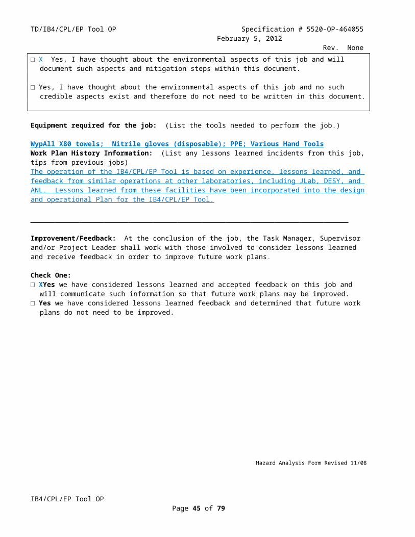
TD/IB4/CPL/EP Tool OP Specification # 5520-OP-464055February 5, 2012
Rev. None MILK OF MAGNESIA. IF INHALED, REMOVE TO FRESH AIR. IF NOT BREATHING, GIVE ARTIFICIAL RESPIRATION. IF BREATHING IS DIFFICULT, GIVE OXYGEN. IN CASE OF CONTACT, IMMEDIATELY FLUSH EYES OR SKIN WITH PLENTY OF WATER FOR AT LEAST 15 MINUTES WHILE REMOVING CONTAMINATED CLOTHING AND SHOES. WASH CLOTHING BEFORE RE-USE.------------------------------------------------------------------------------ 6 - REACTIVITY DATASTABILITY: STABLE HAZARDOUS POLYMERIZATION: WILL NOT OCCURCONDITIONS TO AVOID: MOISTURE, HEATINCOMPATIBLES: WATER, MOST COMMON METALS, ORGANIC MATERIALS, STRONG REDUCING AGENTS, COMBUSTIBLE MATERIALS, STRONG BASES, STRONG OXIDIZING AGENTSDECOMPOSITION PRODUCTS: OXIDES OF SULFUR------------------------------------------------------------------------------ 7 - SPILL AND DISPOSAL PROCEDURESSTEPS TO BE TAKEN IN THE EVENT OF A SPILL OR DISCHARGE WEAR SELF-CONTAINED BREATHING APPARATUS AND FULL PROTECTIVE CLOTHING. STOP LEAK IF YOU CAN DO SO WITHOUT RISK. DO NOT USE WATER. NEUTRALIZE SPILL AND/OR WASHINGS WITH SODA ASH OR LIME. WITH CLEAN SHOVEL, PLACE MATERIAL INTO CLEAN, DRY CONTAINER AND COVER. MOVE CONTAINER(S) FROM SPILL AREA. J. T. BAKER NEUTRASORB(R) OR NEUTRASOL(R) "LOW NA+" ACID NEUTRALIZERS ARE RECOMMENDED FOR SPILLS OF THIS PRODUCT.DISPOSAL PROCEDURE DISPOSE IN ACCORDANCE WITH ALL APPLICABLE FEDERAL, STATE, AND LOCAL ENVIRONMENTAL REGULATIONS.EPA HAZARDOUS WASTE NUMBER: D002, D003 (CORROSIVE, REACTIVE WASTE)------------------------------------------------------------------------------ 8 - PROTECTIVE EQUIPMENTVENTILATION: USE GENERAL OR LOCAL EXHAUST VENTILATION TO MEET TLV REQUIREMENTS.RESPIRATORY PROTECTION: NONE REQUIRED WHERE APPROPRIATE VENTILATION CONDITIONS EXIST. IF THE TLV IS EXCEEDED, A SELF- CONTAINED BREATHING APPARATUS IS ADVISED.EYE/SKIN PROTECTION: SAFETY GOGGLES AND FACE SHIELD, UNIFORM, PROTECTIVE SUIT, RUBBER GLOVES ARE RECOMMENDED.------------------------------------------------------------------------------ 9 - STORAGE AND HANDLING PRECAUTIONSSAF-T-DATA(TM) STORAGE COLOR CODE: WHITE (CORROSIVE)SPECIAL PRECAUTIONS KEEP CONTAINER TIGHTLY CLOSED. STORE IN CORROSION-PROOF AREA. KEEP CONTAINERS OUT OF SUN AND AWAY FROM HEAT.------------------------------------------------------------------------------ 10 - TRANSPORTATION DATA AND ADDITIONAL INFORMATIONDOMESTIC (D.O.T.)PROPER SHIPPING NAME SULFURIC ACIDHAZARD CLASS CORROSIVE MATERIAL (LIQUID)UN/NA UN1830LABELS CORROSIVEREPORTABLE QUANTITY 1000 LBS.INTERNATIONAL (I.M.O.)PROPER SHIPPING NAME SULPHURIC ACIDHAZARD CLASS 8UN/NA UN1830LABELS CORROSIVE
Appendix C.3 Sodium Bicarbonate MSDS_________________________________________________________________________
MSDS FOR SODIUM BICARBONATE PAGE 1 1 - PRODUCT IDENTIFICATION
IB4/CPL/EP Tool OPPage 45 of 59
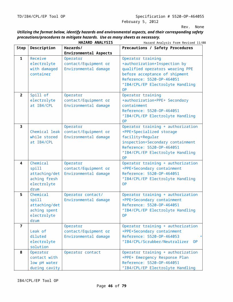
TD/IB4/CPL/EP Tool OP Specification # 5520-OP-464055February 5, 2012
Rev. NonePRODUCT NAME: SODIUM BICARBONATEFORMULA: NAHCO3FORMULA WT: 84.01CAS NO.: 00144-55-8NIOSH/RTECS NO.: VZ0950000COMMON SYNONYMS: BAKING SODA; SODIUM ACID CARBONATEPRODUCT CODES: 3509,3508,3506 EFFECTIVE: 03/20/86 REVISION #01 PRECAUTIONARY LABELLINGBAKER SAF-T-DATA(TM) SYSTEM HEALTH - 0 NONE FLAMMABILITY - 0 NONE REACTIVITY - 1 SLIGHT CONTACT - 1 SLIGHTHAZARD RATINGS ARE 0 TO 4 (0 = NO HAZARD; 4 = EXTREME HAZARD).LABORATORY PROTECTIVE EQUIPMENTSAFETY GLASSES; LAB COATPRECAUTIONARY LABEL STATEMENTS CAUTION MAY CAUSE IRRITATIONDURING USE AVOID CONTACT WITH EYES, SKIN, CLOTHING. WASH THOROUGHLY AFTERHANDLING. WHEN NOT IN USE KEEP IN TIGHTLY CLOSED CONTAINER.SAF-T-DATA(TM) STORAGE COLOR CODE: ORANGE (GENERAL STORAGE)------------------------------------------------------------------------------ 2 - HAZARDOUS COMPONENTS------------------------------------------------------------------------------ COMPONENT % CAS NO. NOT APPLICABLE------------------------------------------------------------------------------ 3 - PHYSICAL DATA------------------------------------------------------------------------------BOILING POINT: N/A VAPOR PRESSURE(MM HG): N/AMELTING POINT: 50 C ( 122 F) VAPOR DENSITY(AIR=1): N/ASPECIFIC GRAVITY: 2.16 EVAPORATION RATE: N/A (H2O=1) (BUTYL ACETATE=1)------------------------------------------------------------------------------MSDS FOR SODIUM BICARBONATE PAGE 2------------------------------------------------------------------------------SOLUBILITY(H2O): MODERATE (1 TO 10 %) % VOLATILES BY VOLUME: 0APPEARANCE & ODOR: ODORLESS WHITE CRYSTALLINE POWDER.------------------------------------------------------------------------------ 4 - FIRE AND EXPLOSION HAZARD DATA------------------------------------------------------------------------------FLASH POINT (CLOSED CUP N/AFLAMMABLE LIMITS: UPPER - N/A % LOWER - N/A %FIRE EXTINGUISHING MEDIA USE EXTINGUISHING MEDIA APPROPRIATE FOR SURROUNDING FIRE.SPECIAL FIRE-FIGHTING PROCEDURES FIREFIGHTERS SHOULD WEAR PROPER PROTECTIVE EQUIPMENT AND SELF-CONTAINED BREATHING APPARATUS WITH FULL FACEPIECE OPERATED IN POSITIVE PRESSURE MODE.TOXIC GASES PRODUCED CARBON MONOXIDE, CARBON DIOXIDE------------------------------------------------------------------------------ 5 - HEALTH HAZARD DATA------------------------------------------------------------------------------TOXICITY: LD50 (ORAL-RAT)(MG/KG) - 4220CARCINOGENICITY: NTP: NO IARC: NO Z LIST: NO OSHA REG: NOEFFECTS OF OVEREXPOSURE DUST MAY IRRITATE SKIN OR EYES.TARGET ORGANS NONE IDENTIFIED
IB4/CPL/EP Tool OPPage 46 of 59

TD/IB4/CPL/EP Tool OP Specification # 5520-OP-464055February 5, 2012
Rev. NoneMEDICAL CONDITIONS GENERALLY AGGRAVATED BY EXPOSURE NONE IDENTIFIEDROUTES OF ENTRY NONE INDICATEDEMERGENCY AND FIRST AID PROCEDURES INGESTION: IF SWALLOWED AND THE PERSON IS CONSCIOUS, IMMEDIATELY GIVE LARGE AMOUNTS OF WATER. GET MEDICAL ATTENTION. INHALATION: IF A PERSON BREATHES IN LARGE AMOUNTS, MOVE THE EXPOSED PERSON TO FRESH AIR. GET MEDICAL ATTENTION. EYE CONTACT: IMMEDIATELY FLUSH WITH PLENTY OF WATER FOR AT LEAST 15 MINUTES. GET MEDICAL ATTENTION. SKIN CONTACT: IMMEDIATELY WASH WITH PLENTY OF SOAP AND WATER FOR AT LEAST 15 MINUTES.------------------------------------------------------------------------------ 6 - REACTIVITY DATA------------------------------------------------------------------------------MSDS FOR SODIUM BICARBONATE PAGE 3------------------------------------------------------------------------------STABILITY: STABLE HAZARDOUS POLYMERIZATION: WILL NOT OCCURCONDITIONS TO AVOID: HEAT, HUMIDITYDECOMPOSITION PRODUCTS: CARBON MONOXIDE, CARBON DIOXIDE------------------------------------------------------------------------------ 7 - SPILL AND DISPOSAL PROCEDURES------------------------------------------------------------------------------STEPS TO BE TAKEN IN THE EVENT OF A SPILL OR DISCHARGE WEAR SUITABLE PROTECTIVE CLOTHING. CAREFULLY SWEEP UP AND REMOVE.DISPOSAL PROCEDURE DISPOSE IN ACCORDANCE WITH ALL APPLICABLE FEDERAL, STATE, AND LOCAL ENVIRONMENTAL REGULATIONS.------------------------------------------------------------------------------ 8 - PROTECTIVE EQUIPMENT------------------------------------------------------------------------------VENTILATION: USE ADEQUATE GENERAL OR LOCAL EXHAUST VENTILATION TO KEEP FUME OR DUST LEVELS AS LOW AS POSSIBLE.RESPIRATORY PROTECTION: NONE REQUIRED WHERE ADEQUATE VENTILATION CONDITIONS EXIST. IF AIRBORNE CONCENTRATION IS HIGH, USE AN APPROPRIATE RESPIRATOR OR DUST MASK.EYE/SKIN PROTECTION: SAFETY GLASSES WITH SIDESHIELDS, PROPER GLOVES ARE RECOMMENDED.------------------------------------------------------------------------------ 9 - STORAGE AND HANDLING PRECAUTIONS------------------------------------------------------------------------------SAF-T-DATA(TM) STORAGE COLOR CODE: ORANGE (GENERAL STORAGE)SPECIAL PRECAUTIONS KEEP CONTAINER TIGHTLY CLOSED. SUITABLE FOR ANY GENERAL CHEMICAL STORAGE AREA.------------------------------------------------------------------------------ 10 - TRANSPORTATION DATA AND ADDITIONAL INFORMATION------------------------------------------------------------------------------DOMESTIC (D.O.T.)PROPER SHIPPING NAME CHEMICALS, N.O.S. (NON-REGULATED)INTERNATIONAL (I.M.O.)PROPER SHIPPING NAME CHEMICALS, N.O.S. (NON-REGULATED)
IB4/CPL/EP Tool OPPage 47 of 59

TD/IB4/CPL/EP Tool OP Specification # 5520-OP-464055February 5, 2012
Rev. None
Appendix D Operating Instructions for the Hand-Held HF Gas Detector__________________________________________________________________________________________________
Model: RKI Eagle
This unit has three active channels. They are for CH4, HF gas and NO2. For electrolyte handling we are only interested in the HF channel.
Maintenance: this unit is to be calibrated every six months
Normal Operating Instructions for HF Gas Detection
Step Operating Procedure for Hand-Held HF Gas Detector Check
1 Press the Power/Enter button. The detector will power up, automatically go through a “Self Diagnosis” procedure, then display HF concentration in PPM (see Figure AF.1)
2 The unit is now ready to sample gas3 Place the end of the sample tube at the desired location for gas sampling
4Wait approximately 10 seconds for the sample to reach the sensor. This number is based on the use of a 1/8” inner diameter tube that is three feet long as the sample probe. It must be scaled for probe length.
5 The reading is now valid
6 To turn unit off, press the Power/Enter button and hold down until a series of 15 audible “beeps” are heard. The unit will display “Good-Bye” and power itself down
7 Store the unit in the EP Tool area PPE cabinet
IB4/CPL/EP Tool OPPage 48 of 59

TD/IB4/CPL/EP Tool OP Specification # 5520-OP-464055February 5, 2012
Rev. None
Figure AF.1 Hand-Held HF Gas Detector Display
IB4/CPL/EP Tool OPPage 49 of 59

TD/IB4/CPL/EP Tool OP Specification # 5520-OP-464055February 5, 2012
Rev. None
IB4/CPL/EP Tool OPPage 50 of 59

TD/IB4/CPL/EP Tool OP Specification # 5520-OP-464055February 5, 2012
Rev. None
IB4/CPL/EP Tool OPPage 51 of 59

TD/IB4/CPL/EP Tool OP Specification # 5520-OP-464055February 5, 2012
Rev. NoneAppendix E Calculation For Generation Of Hydrogen Gas
The process that governs hydrogen generation during electropolishing with the electrolyte described in this document is:
2Nb + 10HF + 2H2O → 2H2NbOF5 + 5H2
The amount of hydrogen generated during a high temperature ( 30C or greater) EP of a single cell ILC cavity is calculated in the spreadsheet shown below, Figure A.E.1. A surface removal rate of 0.8 micrometers per minute is an estimated average surface removal rate for an equatorial removal rate of 0.4 micrometers per minute.
ACrawford 2dec11 Hydrogen Production During ILC 1-Cell Electropolish
Surface Area = 0.1557 [M2]
Reaction = 2Nb -> 5H2
Surface Removal Rate = 0.8 [µm/min] = 1.336E-08 [M/sec]
Volume Removal Rate= 2.08E-09 [M3/sec]
Density = 8.57E+00 [g/cm3] = 8.57E+03 [Kg/M3]
Mass Removal Rate = 1.78E-05 [Kg/sec]
Atomic Mass = 9.29E+01 [gm/mole] = 9.29E-02 [Kg/mole]
Atomic Density = 1.54E-25 [Kg/atom]
Atomic Removal Rate = 1.16E+20 [atom/sec] of Niobium
Atomic H Rate = 2.89E+20 [atom/sec] of Hydrogen
Molecular (H2) Rate = 1.44E+20 [H2/sec] = 2.40E-04 [mole/sec]
Volumetric H2 Rate = 5.37E-03 [Liters/sec] = 5.37E+00 [cc/sec] = 0.32 [Liters/min] @STP
Scrubber "Speed" = 200 [ft3/min] = 5660 [Liters/min]
Dilution = 5.70E-05 = 0.01 %
Figure A.E.1 Calculation of Hydrogen Gas Generated During The EP Of A Single Cell ILC Cavity
IB4/CPL/EP Tool OPPage 52 of 59

TD/IB4/CPL/EP Tool OP Specification # 5520-OP-464055February 5, 2012
Rev. NoneAPPENDIX F EP TOOL/CHEMICAL STOREROOM LOTO
TD-512072IB4/CPL/EP TOOL/CHEMICAL STOREROOM/LOTO
Lock-Out and Tag-Out (LOTO) Procedures
Prepared By:
A. CrawfordDate: 24jan12
EP Tool OPIC Phone Extension:5409
Reviewed By:
Miguel NunezDate:
Phone Extension:4160
Approved By:
Lance Cooley Date:
TD Superconducting Materials
Department Head
Phone Extension:6797
Equipment identification/description: IB4/CPL/EP Tool/Chemical Storeroom(TCP1004)Procedure(s): IB4/CPL /ELECTROLYTE HANDLING OPERATING PROCEDURE (5520-OP-
464051); IB4/CPL /EP TOOL OPERATING PROCEDURE (5520-OP-464055)
Purpose: The purpose of this procedure is to identify specific hazardous energy sources associated with the EP Tool/Chemical Storeroom and the methods used to lock and tag them out to allow safe working conditions. This procedure is an implementation of the Fermilab ES&H Manual, Chapter 5120-Control of Hazardous Energy Sources for Personnel Safety.
All work described in this document must be done under direct supervision of an authorized IB4/CPL/EP Tool operator as described in TD: 5520-OP-464050. Please note the following requirements:
1. Any time that work must be performed inside the EP tool cabinet or inside the chemical storeroom the source of energy for the fluid pumps must be removed by approved LOTO procedures by each worker.
2. Any time that work must be performed inside the EP Tool cabinet the source of energy for the EP tool cathode must be removed by approved LOTO procedures by each worker.
3. It is not necessary for workers to apply LOTO to the EP tool cathode power supply if work is only to be performed inside the chemical storeroom.
4. Work inside the EP tool cabinet or the chemical storeroom requires special PPE. PPE requirements are defined in IB4/CPL /ELECTROLYTE HANDLING OPERATING PROCEDURE (5520-OP-464051)
and IB4/CPL /EP TOOL OPERATING PROCEDURE (5520-OP-464055)
IB4/CPL/EP Tool OPPage 53 of 59

TD/IB4/CPL/EP Tool OP Specification # 5520-OP-464055February 5, 2012
Rev. None
Authorized employees shall perform the steps listed in Table 1 before work is permitted.
LOTO Steps BEFORE Work
Step Name Action Check
1 Notify
The authorized employee shall notify affected employees and interested parties that service is to be performed in the EP tool/chemical storeroom, that the compressed air supply will be shut down, locked out and tagged, and that the EP tool cathode power supply will be locked out and tagged.
2 Prepare
1. The authorized employee shall review this procedure and understand the hazards involved and how to control them.2. Verify the presence of pneumatic power and proper functioning of the compressed air system pressure gage by noting the reading of the pressure gage. The pressure gage should read approximately 60 psi to 70 psi.
3 Shut Down
Mechanical1. The authorized employee shall shut down the EP Tool/Chemical Storeroom compressed air supply by closing the ball valve located near the EP Tool electrical control panel. Please see Figure 1 and Figure 2 for the location of the ball valve. Note: The ball valve controls the sole power source for the EP tool/chemical storeroom fluid pumps.2. The authorized employee shall remove any residual stored pneumatic energy by opening the pressure relief valve and leaving it in the fully opened position.ElectricalThe authorized employee shall shut down the EP tool cathode power supply by removing the electrical AC power cord from its receptacle.
4 Isolate
MechanicalIsolation of the the EP tool/chemical storeroom fluid pumps from their energy source is achieved when the ball valve is placed in the “Closed” position as per step number 3.ElectricalThe EP tool cathode power supply shall be isolated from its energy source by applying a locking safety cover over the end of the AC power cord. Cover shall be Electrical Plug Lockout 3-1/2" Dia. X 6-1/4" Height, 5/16" Max Shackle Dia. McMaster-Carr Item# 10645A65, or equivalent.
5 Apply Lock and Tag
Mechanical1. The authorized employee shall place a red FNAL LOTO lock and approved “Danger-Do Not Operate” tag on the closed ball valve. The valve shall be locked closed in a way so that it cannot be opened unless the lock is removed.Electrical2. The authorized employee shall place a red FNAL LOTO lock and approved “Danger-Do Not Operate” tag on the closed safety cover for the EP tool cathode power supply AC power cord. See Figure 3.
6 Verify
MechanicalVerify the absence of pneumatic power for the fluid pumps by reading the pressure gage and by double checking that the pressure relief valve is fully opened. The pressure gage should read zero psi after the pressure relief valve has been opened.ElectricalThe EP tool cathode power supply is not capable of storing a significant amount of energy after it has been disconnected from its AC power source.
Table 1. LOTO Steps BEFORE Work
It is now permitted for the specified work to be performed.
IB4/CPL/EP Tool OPPage 54 of 59

TD/IB4/CPL/EP Tool OP Specification # 5520-OP-464055February 5, 2012
Rev. NoneThe authorized employee(s) who applied the lock(s) and tag(s) shall perform the steps listed in Table 2 in order to return the EP tool/chemical storeroom to service:
LOTO Steps AFTER Work
Step Name Action Check
1 Check Equipment Check all the equipment for proper installation, leaks, etc.
2 Check Work Area Make sure that the area is clear for operation.
3 Verify Verify that the EP tool/chemical storeroom controls are all in the “Off” position.
4 Remove the Locks and Tags
Mechanical1. Close the pressure relief valve2. Each worker should remove their own LOTO from the ball valveElectricalEach worker should remove their own LOTO from the electrical plug lockout on the EP tool cathode power supply
5 Notify
MechanicalNotify affected employees that the compressed air system of the EP Tool/Chemical Storeroom is now in operational mode. It is now permitted to open the ball valve and operate the EP tool/chemical storeroom.ElectricalNotify affected employees that the EP tool cathode power supply is now in operational mode. It is now permitted to replace the electrical plug in its receptacle.
Table 2. LOTO Steps AFTER Work
The EP tool/chemical storeroom may now be returned to service.
IB4/CPL/EP Tool OPPage 55 of 59

TD/IB4/CPL/EP Tool OP Specification # 5520-OP-464055February 5, 2012
Rev. None
Room C
Utilities Room
Room D
Mechanical Work Area
Chemical Work Area
Chemical Store room
Furnace
Class 10 Clean Room
Mens & Womens Restrooms
Stairwell
Janitors Closet
Red Doors Internal Locking Doors White Doors Internal Non-Locking Doors Green Doors Exit Only Doors Black Doors External Locking Doors
IB4 Main Floor
Quality
Stairwell
Office Office
Only Entrance to the CPL with visual and audible indicators
Second set of visual and audible indicators
EP Tool
Sulfuric Acid Muriatic Acid
Storage
Sodium Hydroxide
Storage
Day Tanks
Scrubber / Neutralizer
Figure 1. Location Of The Compressed Air Supply Isolation Ball Valve For The EP Tool/Chemical Storeroom
IB4/CPL/EP Tool OPPage 56 of 59
Apply LOTO HereFluid pump
Compressed Air Supply
Apply LOTO HereEP Tool Cathode
Power Supply

TD/IB4/CPL/EP Tool OP Specification # 5520-OP-464055February 5, 2012
Rev. None
Figure 2. LOTO Applied To Valve for EP Tool/Chemical Storeroom Fluid Pump Energy Source
Figure 3. LOTO Applied To Power Cord For EP Tool Cathode Power Supply
IB4/CPL/EP Tool OPPage 57 of 59
Pressure Gage Pressure
Relief Valve
System Isolation
Valve

TD/IB4/CPL/EP Tool OP Specification # 5520-OP-464055February 5, 2012
Rev. NoneAppendix G FNAL Illinois Wastewater Permit Application Excerpt
IB4/CPL/EP Tool OPPage 58 of 59

TD/IB4/CPL/EP Tool OP Specification # 5520-OP-464055February 5, 2012
Rev. None
IB4/CPL/EP Tool OPPage 59 of 59