vdrive – control systems dcs1 - vahle.com · 3 status information every vdrive dcs system is...
TRANSCRIPT

1
vDRIVE – CONTROL SYSTEMS DCS1
11A | EN 2018

2
vDRIVE – KEY HIGHLIGHTS
SYSTEM VAHLE vDRIVE system provides a wide range of power stages between
0.75 kW and 1.5kW which offers a perfect match up for any Electrifi ed
Monorail System (EMS). Additionally, a wide range of I/O allows a ma-
ximum fl exibility in any application. The vDRIVE portfolio also includes
equipments for positioning, distance control and communication.
CERTIFICATIONS VAHLE vDRIVE fulfi lls all required standards and conforms to the ‚Low
Voltage Directive‘, EMC requirements and specifi c test methods, and
the Electromagnetic Compatibility Regulations.
COMMUNICATION Communication between stationary and mobile consumers becomes a
more important role in automated processes. VAHLE vDRIVE systems
provide many different communication systems to ensure the best so-
lution for your application. The options include the half wave bus, rail
bus and VAHLE SMGM – the exclusive slotted microwave guide mini
solution.
3
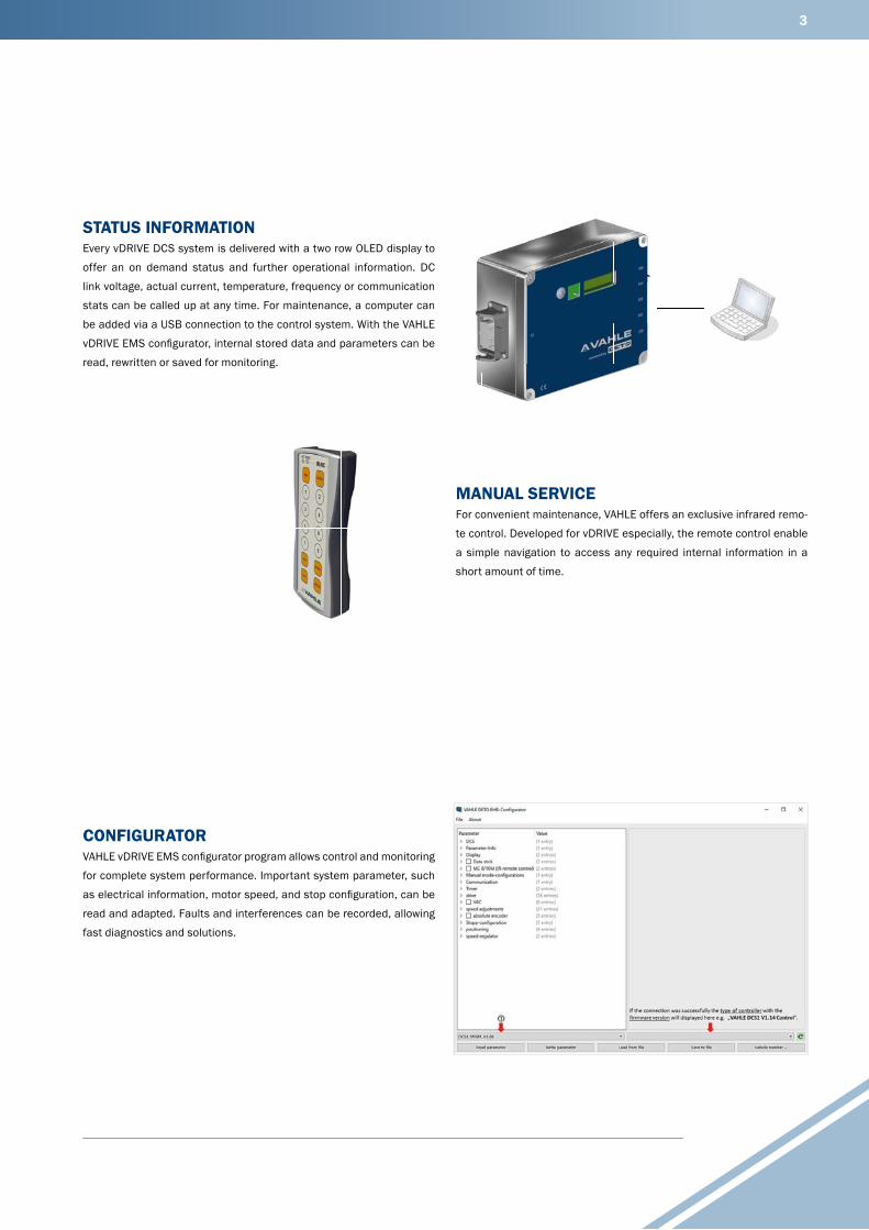
STATUS INFORMATION Every vDRIVE DCS system is delivered with a two row OLED display to
offer an on demand status and further operational information. DC
link voltage, actual current, temperature, frequency or communication
stats can be called up at any time. For maintenance, a computer can
be added via a USB connection to the control system. With the VAHLE
vDRIVE EMS confi gurator, internal stored data and parameters can be
read, rewritten or saved for monitoring.
MANUAL SERVICE For convenient maintenance, VAHLE offers an exclusive infrared remo-
te control. Developed for vDRIVE especially, the remote control enable
a simple navigation to access any required internal information in a
short amount of time.
CONFIGURATOR VAHLE vDRIVE EMS confi gurator program allows control and monitoring
for complete system performance. Important system parameter, such
as electrical information, motor speed, and stop confi guration, can be
read and adapted. Faults and interferences can be recorded, allowing
fast diagnostics and solutions.

4
vDRIVE– SYSTEM OVERVIEW
DCS1
APOS Optic Reading Head (underlying)
Railbus Collector (underlying)
Positioning
Motor*
EMS Trolly*
APOS Optic Codestrip
SMGM Profi le
Electrical Monorail System U10
EMS Profi le*
* The EMS components are not part of VAHLE delivery scope.

5
6
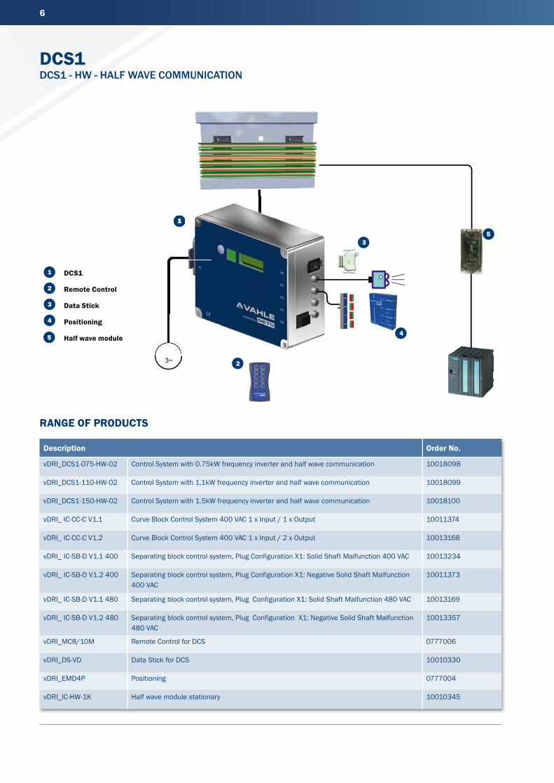
DCS1DCS1 - HW - HALF WAVE COMMUNICATION
Description Order No.
vDRI_DCS1-075-HW-02 Control System with 0.75kW frequency inverter and half wave communication 10018098
vDRI_DCS1-110-HW-02 Control System with 1.1kW frequency inverter and half wave communication 10018099
vDRI_DCS1-150-HW-02 Control System with 1.5kW frequency inverter and half wave communication 10018100
vDRI_ IC-CC-C V1.1 Curve Block Control System 400 VAC 1 x Input / 1 x Output 10011374
vDRI_ IC-CC-C V1.2 Curve Block Control System 400 VAC 1 x Input / 2 x Output 10013168
vDRI_ IC-SB-D V1.1 400 Separating block control system, Plug Configuration X1: Solid Shaft Malfunction 400 VAC 10013234
vDRI_ IC-SB-D V1.2 400 Separating block control system, Plug Configuration X1: Negative Solid Shaft Malfunction 400 VAC
10011373
vDRI_ IC-SB-D V1.1 480 Separating block control system, Plug Configuration X1: Solid Shaft Malfunction 480 VAC 10013169
vDRI_ IC-SB-D V1.2 480 Separating block control system, Plug Configuration X1: Negative Solid Shaft Malfunction 480 VAC
10013357
vDRI_MC8/10M Remote Control for DCS 0777006
vDRI_DS-VD Data Stick for DCS 10010330
vDRI_EMD4P Positioning 0777004
vDRI_IC-HW-1K Half wave module stationary 10010345
RANGE OF PRODUCTS
M 3~ 2
1
1
2
3
4
5
5
M
1
3
4
DCS1
Remote Control
Data Stick
Positioning
Half wave module

7
Power Specifi cation Nominal power .............................. 0.75kW/1.1kW/1.5kW
Supply voltage ............................... 400 ... 480VAC ±10%
3 phase symmetric
Supply net system ........................ TT, TN (grounded neutral)
Inrush current peak ...................... 6 A
Supply frequency .......................... 45 ... 65 Hz
Output curent nominal ................. 1.8 A/2.6 A/3.5 A
Output current peak (60s) ........... 3.0 A/4.0 A/5.0 A
Output frequency .......................... 0 ... 120 kHz
Power loss ..................................... 22W/40W/60W
Auxilliary (external Sensors) ........ 24VDC, ±10%, 0.5A
Nominal voltage break ................. 185VDC
Maximum current break ............... 0.5ADC
Communication Broadcast ...................................... Conductor bar
Technology .................................... Coal
Absolute adress participant ........ n/a
Max. participants/segment ......... n/a
Data rate ....................................... n/a
Transmission ................................. n/a
Fieldbus mobile ............................ n/a
Equipment (stationery/mobile) .... Integrated in DCS
Positioning ..................................... EMD4P
Mechanical Specifi cation Dimension* ................................... 280 x 230 x 110mm
Ambient temperature ................... 0 ... + 40 °C non-condensing
Shock ............................................. 3M4
Vibration ........................................ 7M2
Environment .................................. General industrial
Cooling ........................................... Convection
Protection rating ........................... 3K3 (-10...+45 °C) @ 100 % duty
3K3 (-0...+50 °C) @ 70 % duty
Connection Power X1 ................... VAHLE connector
Connection Motor X2 ................... Harting HAN10B, 10-pole+PE
Adapter for I/O .............................. SA02
* Please notice the different dimensions of DCS with 1.5 kW nominal power: 280 x230 x140 mm.
TECHNICAL DATA BLOCK DIAGRAM
DIMENSIONS
DCS1 X1
X22X21X20 X23 X40
SA02
LINE
FI
LTER
X2
CONV
ERTE
R
R-CH
OPP
ER
S1
OLED-DISPLAY
IR
USB
CPU
2 x
DI, 5
-PO
LESE
NSO
R
1 x
DI, 1
x D
O, 4
-PO
LESE
NSO
R
5 x
DI, 1
x D
O, 8
-PO
LEEM
D4P
RS48
5, 5
-PO
LESE
NSO
R
EXTE
RNAL
D
ATAP
LUG
SWITCH ON/OFF
POWER OUTPUT
POWER SUPPLY

8
DCS1DCS1 - RB - RAILBUS
Description Order No.
vDRI_DCS1-075-RB-02 Control System with 0.75kW frequency inverter and half railbus communication 10018095
vDRI_DCS1-110-RB-02 Control System with 1.1kW frequency inverter and half railbus communication 10018096
vDRI_DCS1-150-RB-02 Control System with 1.5kW frequency inverter and half railbus communication 10018097
vDRI_ IC-SB-D V1.3 400 Separating block control system, Plug Configuration X1: Malfunction signaling contact N.C. 24 VDC, 400 VAC
10013361
vDRI_ IC-SB-D V1.2 480 Separating block control system, Plug Configuration X1: Malfunction signaling contact N.C. 24 VDC, 480 VAC
10013362
vDRI_MC8/10M Remote Control 0777006
vDRI_DS-VD Data Stick 10010330
APOS Optic See vPOS catalogue
vDRI_IC-PCB-2k-PN Railbus Module Stationary 10011521
vDRI_Functionbloc/TIA_Portal Option
RANGE OF PRODUCTSC
H1
CH
2
M 3~
1
2
3
4
5
1
2
3
5
4
M
1
DCS1
Remote Control
Data Stick
APOS optic
Railbus Module

9
TECHNICAL DATA
* Please notice the different dimensions of DCS with 1.5 kW nominal power: 280 x 230 x 140 mm.
BLOCK DIAGRAM
DIMENSIONS
Power Specifi cation Nominal power .............................. 0.75 kW/1.1 kW/1.5 kW
Supply voltage ............................... 400 ... 480VAC ±10%
3 phase symmetric
Supply net system ........................ TT, TN (grounded neutral)
Inrush current peak ...................... 6A
Supply frequency .......................... 45 ... 65 Hz
Output curent nominal ................. 1.8 A/2.6 A/3.5 A
Output current peak (60s) ........... 3.0 A/4.0 A/5.0 A
Output frequency .......................... 0 ... 120 kHz
Power loss ..................................... 22W/40W/60W
Auxilliary (external Sensors) ........ 24VDC, ±10%, 0.5A
Nominal voltage break ................. 185VDC
Maximum current break ............... 0.5ADC
Communication Broadcast ...................................... Conductor bar
Technology .................................... Coal
Absolute adress participant ........ n/a
Max. participants/segment ......... n/a
Data rate ....................................... n/a
Transmission ................................. n/a
Fieldbus mobile ............................ n/a
Equipment (stationery/mobile) .... Integrated in DCS
Positioning ..................................... APOS Optic
Mechanical Specifi cation Dimension*. .................................. 280 x 230 x 110 mm
Ambient temperature ................... 0 ... + 40 °C non-condensing
Shock ............................................. 3M4
Vibration ........................................ 7M2
Environment .................................. General industrial
Cooling ........................................... Convection
Protection rating ........................... 3K3 (-10...+45 °C) @ 100 % duty
3K3 (-0...+50 °C) @ 70 % duty
Connection Power X1 ................... VAHLE connector
Connection Motor X2 ................... Harting HAN10B, 10-pole+PE
Adapter for I/O .............................. SA02
DCS1 X1
X22X21X20 X23 X40
SA02
LINE
FI
LTER
X2
CONV
ERTE
R
R-CH
OPP
ER
S1
OLED-DISPLAY
IR
USB
CPU
2 x
DI, 5
-PO
LESE
NSO
R
1 x
DI, 1
x D
O, 4
-PO
LESE
NSO
R
5 x
DI, 1
x D
O, 8
-PO
LESE
NSO
R
RS48
5, 5
-PO
LEAP
OS
optic
EXTE
RNAL
D
ATAP
LUG
SWITCH ON/OFF
POWER OUTPUT
POWER SUPPLY
10
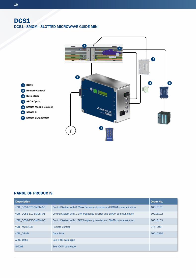
DCS1 DCS1 - SMGM - SLOTTED MICROWAVE GUIDE MINI
Description Order No.
vDRI_DCS1-075-SMGM-06 Control System with 0.75kW frequency inverter and SMGM communication 10018101
vDRI_DCS1-110-SMGM-06 Control System with 1.1kW frequency inverter and SMGM communication 10018102
vDRI_DCS1-150-SMGM-06 Control System with 1.5kW frequency inverter and SMGM communication 10018103
vDRI_MC8/10M Remote Control 0777006
vDRI_DS-VD Data Stick 10010330
APOS Optic See vPOS catalogue
SMGM See vCOM catalogue
RANGE OF PRODUCTS
1
2
3
4
5
M 3~
2
1
3
6
7
1
6
7
45
DCS1
Remote Control
Data Stick
APOS Optic
SMGM Mobile Coupler
SMGM SI
SMGM BCC/SMGM

11
TECHNICAL DATA
* Please notice the different dimensions of DCS with 1.5 kW nominal power: 280 x230 x140 mm.
BLOCK DIAGRAM
DIMENSIONS
Power Specifi cation Nominal power .............................. 0.75 kW/1.1 kW/1.5 kW
Supply voltage ............................... 400 ... 480 VAC ± 10 %
3 phase symmetric
Supply net system ........................ TT, TN (grounded neutral)
Inrush current peak ...................... 6 A
Supply frequency .......................... 45 ... 65 Hz
Output curent nominal ................. 1.8A/2.6A/3.5A
Output current peak (60s) ........... 3.0A/4.0A/5.0A
Output frequency .......................... 0 ... 120 kHz
Power loss ..................................... 22 W/40 W/60 W
Auxilliary (external Sensors) ........ 24 VDC, ± 10 %, 0.5 A
Nominal voltage break ................. 185 VDC
Maximum current break ............... 0.5 ADC
Communication Broadcast ...................................... Slotted waveguide
Technology .................................... Reading head
Absolute adress participant ........ n/a
Max. participants/segment ......... n/a
Data rate ....................................... n/a
Transmission ................................. n/a
Fieldbus mobile ............................ n/a
Equipment (stationery/mobile) .... Integrated in DCS
Positioning ..................................... APOS Optic
Mechanical Specifi cation Dimension* ................................... 280 x 230 x 110 mm
Ambient temperature ................... 0 ... + 40 °C non-condensing
Shock ............................................. 3M4
Vibration ........................................ 7M2
Environment .................................. General industrial
Cooling ........................................... Convection
Protection rating ........................... 3K3 (-10...+45°C) @ 100% duty
3K3 (-0...+50°C) @ 70% duty
Connection Power X1 ................... VAHLE connector
Connection Motor X2 ................... Harting HAN10B, 10-pole+PE
Adapter for I/O .............................. SA06
DCS1 X1
X22X21X20 X23 X40
SA06
LINE
FI
LTER
X2
CONV
ERTE
R
R-CH
OPP
ER
S1
OLED-DISPLAY
IR
USB
CPU
2 x
DI, 5
-PO
LESE
NSO
R
1 x
DI, 1
x D
O, 4
-PO
LESE
NSO
R
SYN
CBU
SBC
C/SM
GM
RS48
5, 5
-PO
LEAP
OS
optic
EXTE
RNAL
D
ATAP
LUG
SWITCH ON/OFF
POWER OUTPUT
POWER SUPPLY
Paul Vahle GmbH & Co. KGWesticker Str. 52
59174 KamenGermany
Tel.: +49 2307 704-0Fax: +49 2307 704-444
www.vahle.com
W25
2612
6/00
-E/e
n |
1000
| R
ev.0
2 |
02/1
8 |
Erro
rs a
nd te
chni
cal m
odifi
catio
ns s
ubje
ct to
cha
nge.