vco ppt
DESCRIPTION
Voltage Controlled OscillatorTRANSCRIPT
VOLTAGE CONTROLLED
OSCILLATOR USING ADC
INTRODUCTION
A voltage-controlled oscillator or VCO is an electronic oscillator designed to be controlled in oscillation frequency by a voltage input. The frequency of oscillation is varied by the applied DC voltage, while modulating signals may also be fed into the VCO to cause frequency modulation (FM) or phase modulation (PM).
There are various ways in which one can implement a VCO. The current starved VCO is the most common. We have used a different approach here to achieve the same operation.
Our design contains:
•Ring oscillator
•Multiplexer
•Analog to Digital Converter (ADC)
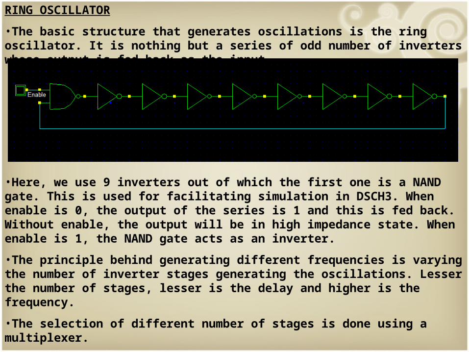
RING OSCILLATOR
•The basic structure that generates oscillations is the ring oscillator. It is nothing but a series of odd number of inverters whose output is fed back as the input.
•Here, we use 9 inverters out of which the first one is a NAND gate. This is used for facilitating simulation in DSCH3. When enable is 0, the output of the series is 1 and this is fed back. Without enable, the output will be in high impedance state. When enable is 1, the NAND gate acts as an inverter.
•The principle behind generating different frequencies is varying the number of inverter stages generating the oscillations. Lesser the number of stages, lesser is the delay and higher is the frequency.
•The selection of different number of stages is done using a multiplexer.
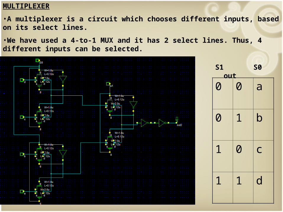
MULTIPLEXER
•A multiplexer is a circuit which chooses different inputs, based on its select lines.
•We have used a 4-to-1 MUX and it has 2 select lines. Thus, 4 different inputs can be selected.
0 0 a
0 1 b
1 0 c
1 1 d
S1 S0 out
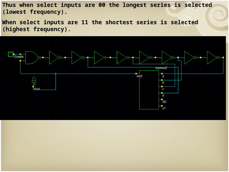
Thus when select inputs are 00 the longest series is selected (lowest frequency).
When select inputs are 11 the shortest series is selected (highest frequency).
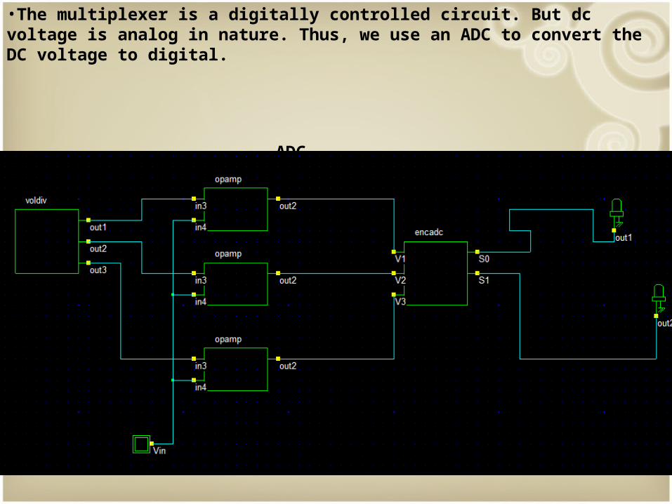
•The multiplexer is a digitally controlled circuit. But dc voltage is analog in nature. Thus, we use an ADC to convert the DC voltage to digital.
ADC

The ADC has three parts:
Voltage divider
Comparator (open loop op-amp)
Encoder
Voltage divider : We use transmission gates that are always ON instead of resistances to divide the voltage. By trial and error, a voltage divider with a combination of pass transistors and transmission gates was constructed. As we are using 0.12 micrometer technology, Vdd is 1.2V and this is divided into 4 approximately equal steps- 0.25V, 0.55V, 0.85V and 1.2V

•The transistor level of open loop opamp is shown. Our analog input signal is given to the inverting terminal of the opamp and the reference voltage from the voltage divider network is given to the non-inverting terminal.
•Thus, when input voltage is lesser than the reference, comparator output is HIGH.
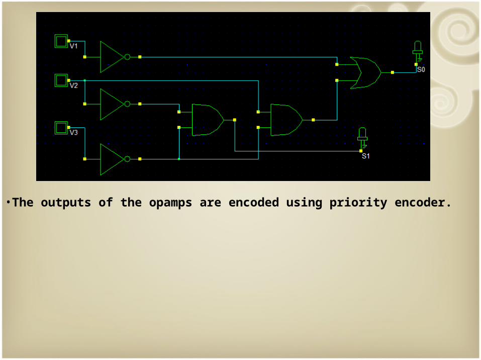
•The outputs of the opamps are encoded using priority encoder.
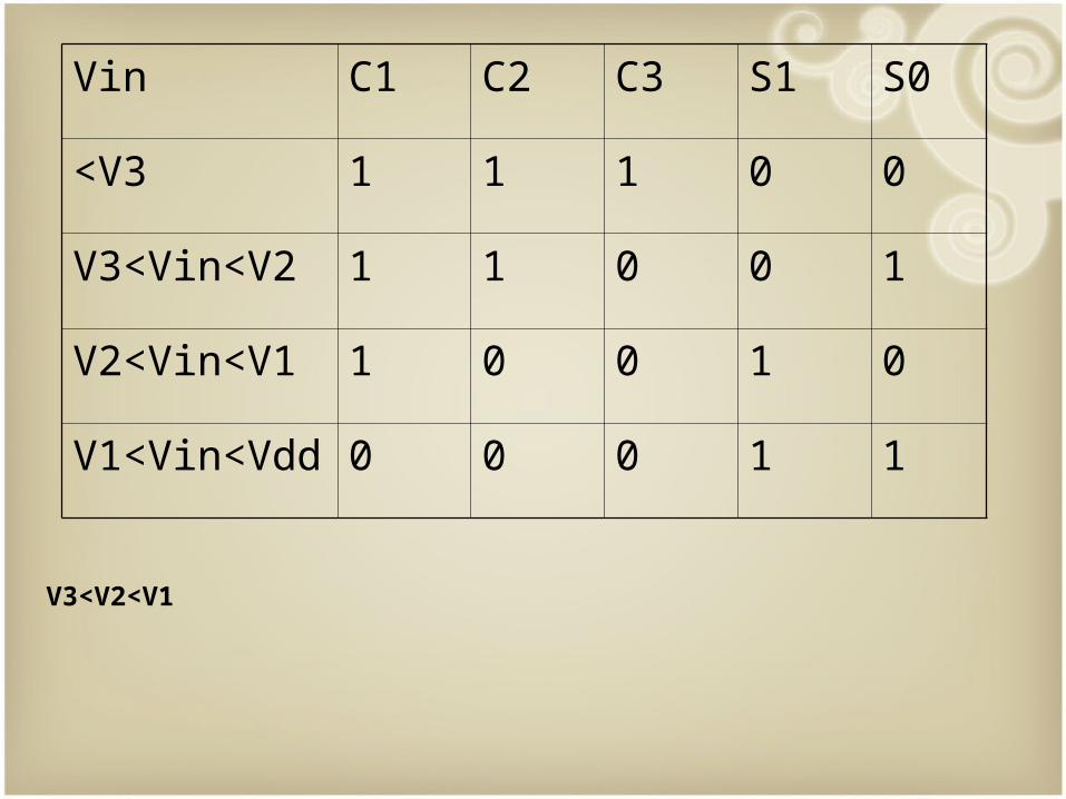
Vin C1 C2 C3 S1 S0
<V3 1 1 1 0 0
V3<Vin<V2 1 1 0 0 1
V2<Vin<V1 1 0 0 1 0
V1<Vin<Vdd 0 0 0 1 1
V3<V2<V1

•All the components are connected together and the final VCO is shown below.
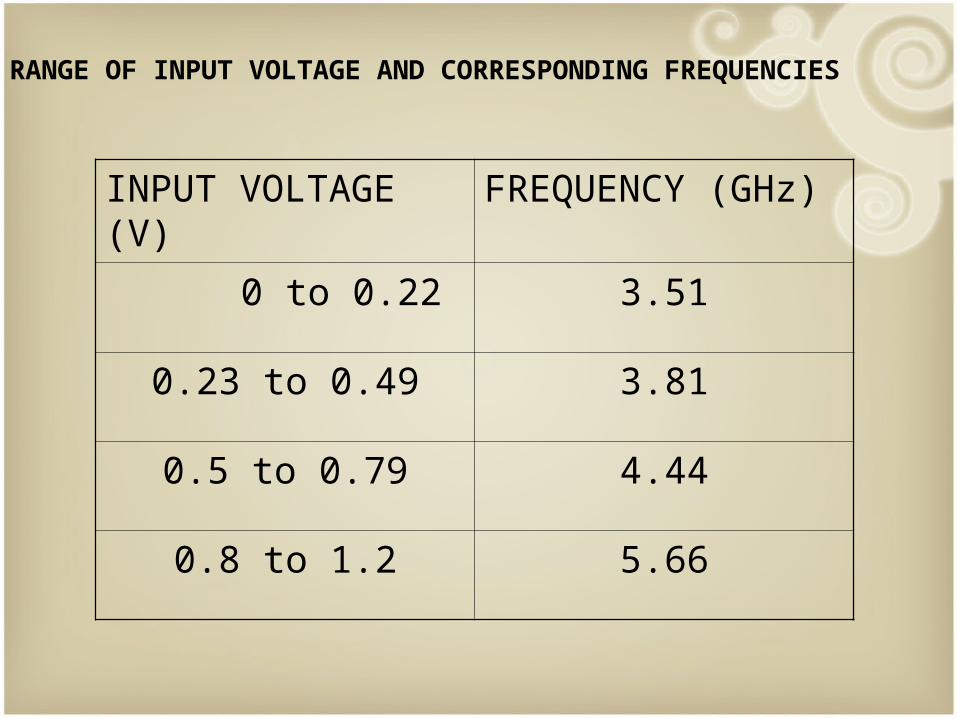
INPUT VOLTAGE (V) FREQUENCY (GHz)
0 to 0.22 3.51
0.23 to 0.49 3.81
0.5 to 0.79 4.44
0.8 to 1.2 5.66
RANGE OF INPUT VOLTAGE AND CORRESPONDING FREQUENCIES

LAYOUT OF VCO

SNAPSHOTS OF SIMULATION IN MICROWIND Vin = 0V to 0.22V

Vin = 0.23V to 0.49V

Vin = 0.5V to 0.79V

Vin = 0.8V to 1.2V
The frequencies may vary depending upon the software and components used.
VCOs are used in:
•Electronic jamming equipment•Function Generators•The production of electronic music, to generate variable tones,•Phase-locked loops•Frequency synthesizers used in communication equipment.
Voltage-to-Frequency converters are voltage-controlled oscillators, with a highly linear relation between applied voltage and frequency. They are used to convert a slow analog signal (such as from a temperature transducer) to a digital signal for transmission over a long distance, since the frequency will not drift or be affected by noise. VCOs may have sine and/or square wave outputs. Function generators are low-frequency oscillators which feature multiple waveforms, typically sine, square, and triangle waves. Monolithic function generators are voltage-controlled. Analog phase-locked loops typically contain VCOs. High-frequency VCOs are usually used in phase-locked loops for radio receivers. Phase noise is the most important specification for them. Low-frequency VCOs are used in analog music synthesizers. For these, sweep range, linearity, and distortion are often most important specs. Since music synthesis is nowadays done digitally, the market for audio-frequency VCOs has largely disappeared.
APPLICATIONS

ACKNOWLEDGEMENTS
Behind every achievement lies an unfathomable sea of gratitude to those who actuated it, without whom it would never have come into existence. To them we lay the words of gratitude imprinted not just in paper but also deep in our hearts.
We express our sincere gratitude towards Mrs. A.R.Priyarenjini, Professor, Department of Electronics and Communication, MSRIT, for constantly supporting us and without whose invaluable guidance, the successful completion of the project would not have been possible.
REFERENCES
•The Designer’s Guide to Jitter in Ring Oscillators by John A. McNeill and David S. Ricketts
•www.microwind.net