various ammonia technology
TRANSCRIPT
1
Presented By,Prem BabooSr. Manager(Prod)National Fertilizers Ltd. Vijaipur, India
2
To understand how to utilize feed stock
efficiently
To reduce plant down time
To improve man & machine safety
To reduce pollution level
To reduce capital cost
To optimize the process
3
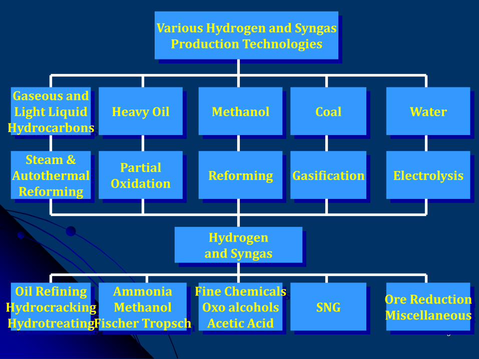
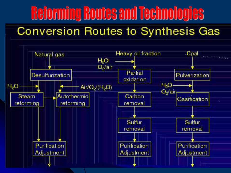
Various Hydrogen and SyngasProduction Technologies
Gaseous andLight Liquid
HydrocarbonsHeavy Oil Methanol Coal Water
Steam &Autothermal
Reforming
PartialOxidation
Reforming Gasification Electrolysis
Hydrogenand Syngas
Oil RefiningHydrocrackingHydrotreating
AmmoniaMethanol
Fischer Tropsch
Fine ChemicalsOxo alcoholsAcetic Acid
SNGOre ReductionMiscellaneous
4
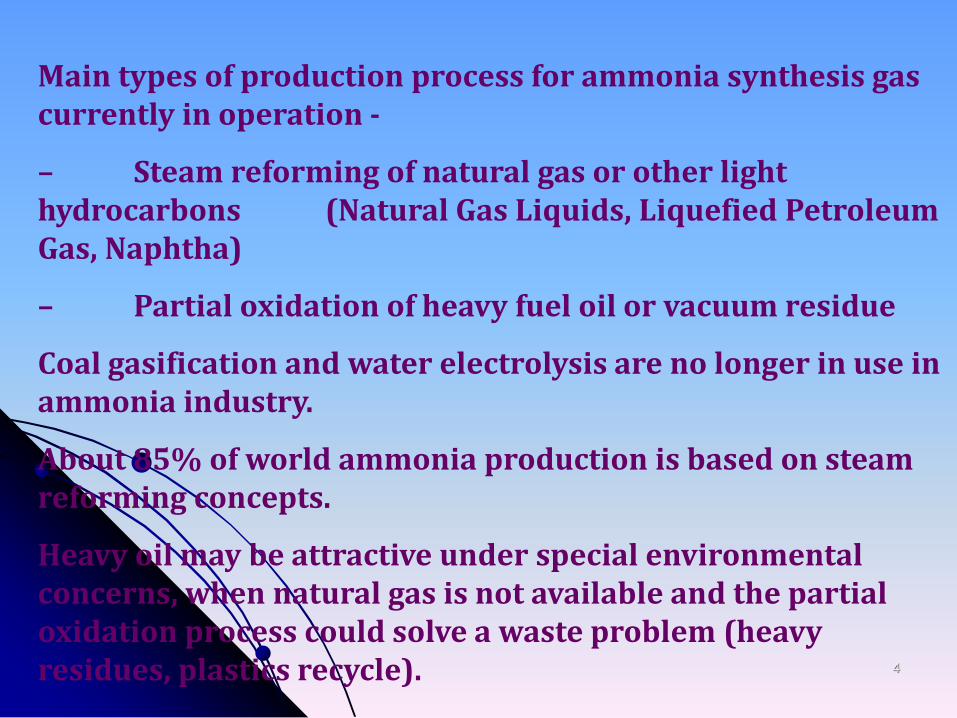
Main types of production process for ammonia synthesis gas currently in operation -
– Steam reforming of natural gas or other light hydrocarbons (Natural Gas Liquids, Liquefied Petroleum Gas, Naphtha)
– Partial oxidation of heavy fuel oil or vacuum residue
Coal gasification and water electrolysis are no longer in use in ammonia industry.
About 85% of world ammonia production is based on steam reforming concepts.
Heavy oil may be attractive under special environmental concerns, when natural gas is not available and the partial oxidation process could solve a waste problem (heavy residues, plastics recycle).
5
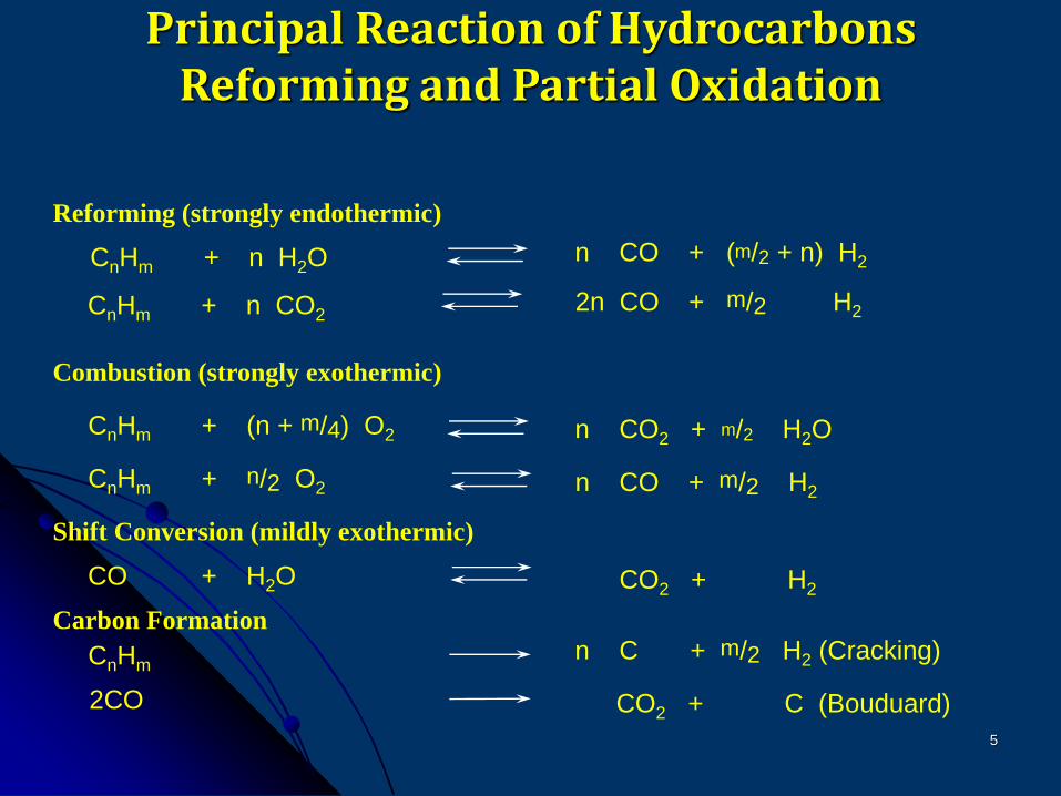
Principal Reaction of HydrocarbonsReforming and Partial Oxidation
Reforming (strongly endothermic)
CnHm + n H2O n CO + (m/2 + n) H2
CnHm + n CO22n CO + m/2 H2
Combustion (strongly exothermic)
CnHm + (n + m/4) O2 n CO2 + m/2 H2O
CnHm + n/2 O2 n CO + m/2 H2
Shift Conversion (mildly exothermic)
CO + H2O CO2 + H2
Carbon Formation
CnHmn C + m/2 H2 (Cracking)
2CO CO2 + C (Bouduard)
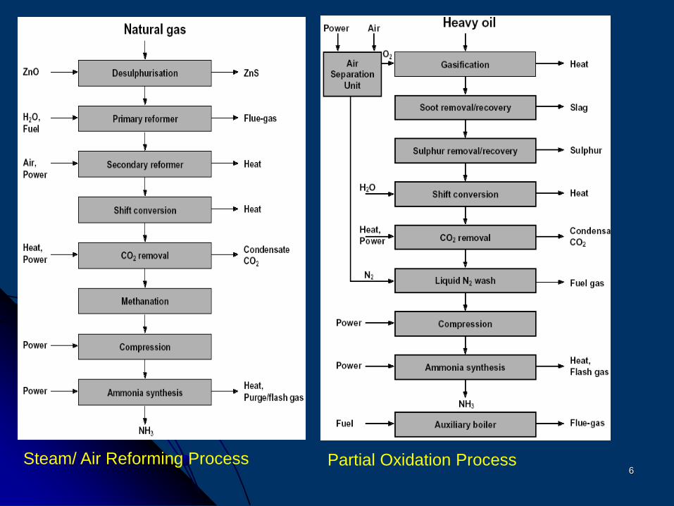
6Steam/ Air Reforming Process Partial Oxidation Process
7
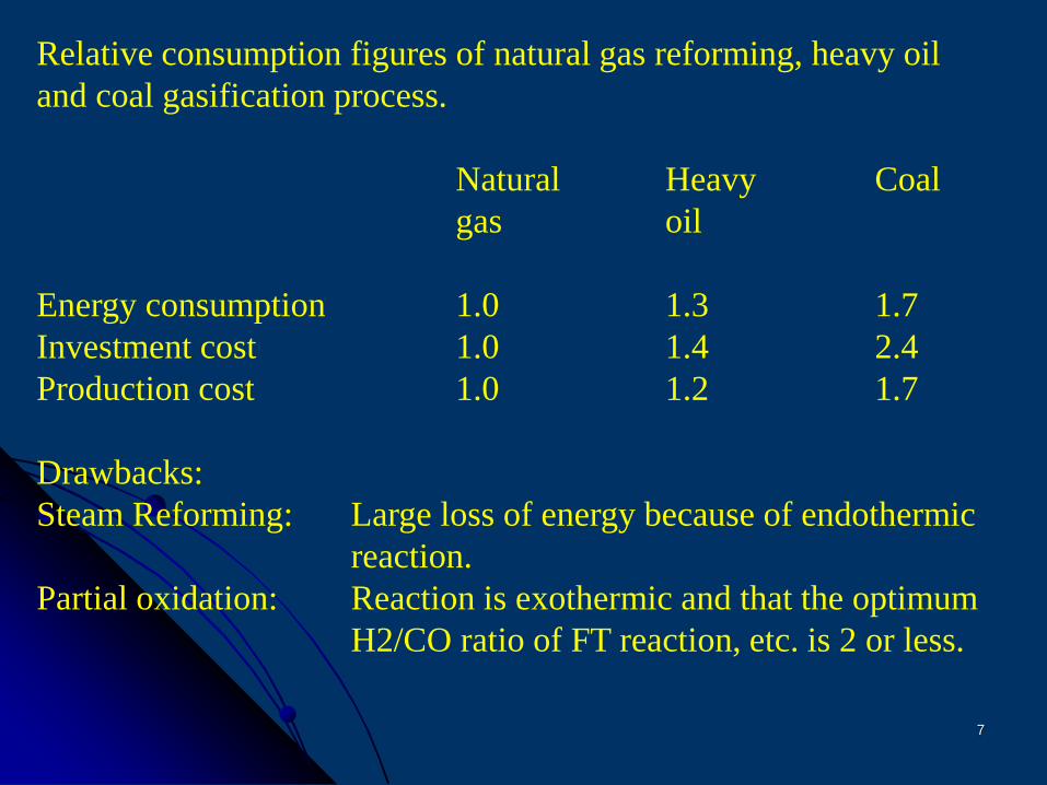
Relative consumption figures of natural gas reforming, heavy oil
and coal gasification process.
Natural Heavy Coal
gas oil
Energy consumption 1.0 1.3 1.7
Investment cost 1.0 1.4 2.4
Production cost 1.0 1.2 1.7
Drawbacks:
Steam Reforming: Large loss of energy because of endothermic
reaction.
Partial oxidation: Reaction is exothermic and that the optimum
H2/CO ratio of FT reaction, etc. is 2 or less.
8
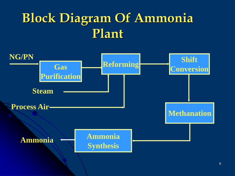
Block Diagram Of Ammonia Plant
Gas
Purification
ReformingShift
Conversion
Methanation
Ammonia
Synthesis
Steam
Process Air
NG/PN
Ammonia
9
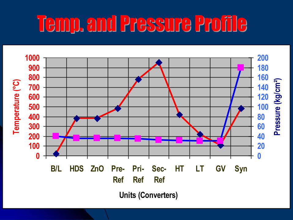
0
100200
300400
500
600700
800900
1000
B/L HDS ZnO Pre-
Ref
Pri-
Ref
Sec-
Ref
HT LT GV Syn
Units (Converters)
Tem
per
atu
re (
°C)
0
2040
6080
100
120140
160180
200
Pre
ssu
re (
kg/c
m²)
10
11
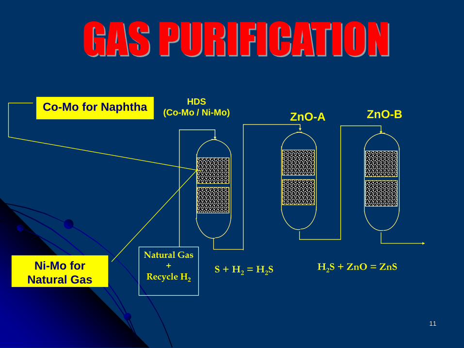
Natural Gas+
Recycle H2
HDS
(Co-Mo / Ni-Mo) ZnO-A ZnO-B
S + H2 = H2SH2S + ZnO = ZnS
Co-Mo for Naphtha
Ni-Mo for
Natural Gas
12
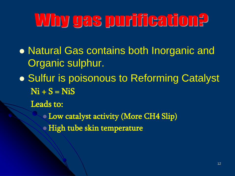
Natural Gas contains both Inorganic and
Organic sulphur.
Sulfur is poisonous to Reforming Catalyst
Ni + S = NiS
Leads to:
Low catalyst activity (More CH4 Slip)
High tube skin temperature

13
Organic Sulfur can not be removed.
Difficult to analyze.
Both HDS and The ZnO catalysts are
not fully utilized
Sulfur slip can only be detected with
lab. Analysis
Life of catalyst can not be determined
unless lab. tests
14
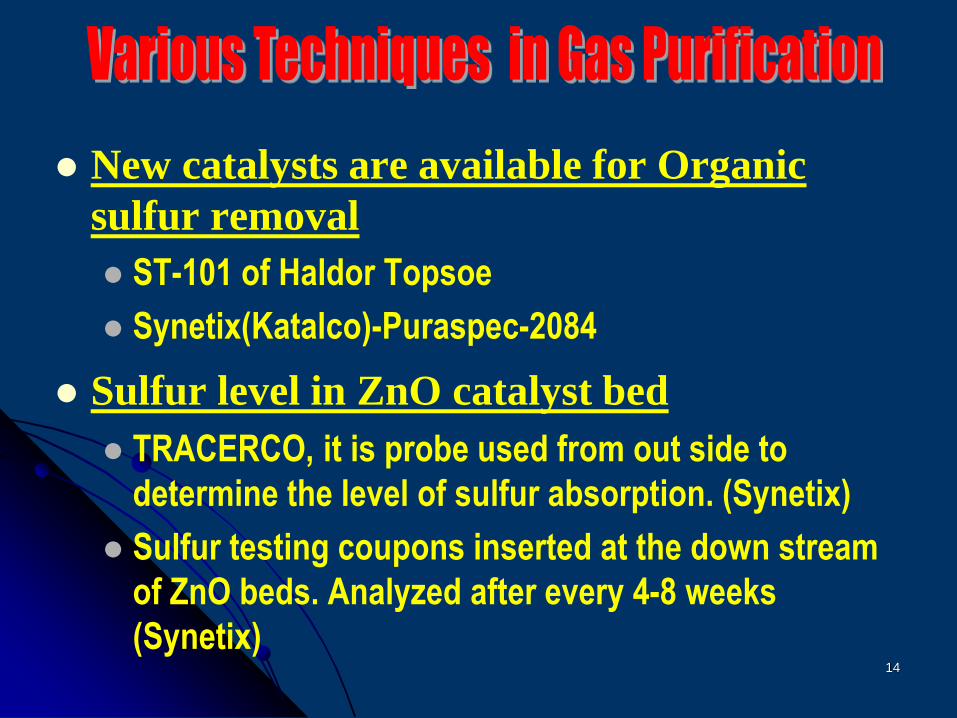
New catalysts are available for Organic
sulfur removal
ST-101 of Haldor Topsoe
Synetix(Katalco)-Puraspec-2084
Sulfur level in ZnO catalyst bed
TRACERCO, it is probe used from out side to
determine the level of sulfur absorption. (Synetix)
Sulfur testing coupons inserted at the down stream
of ZnO beds. Analyzed after every 4-8 weeks
(Synetix)

15
16
17
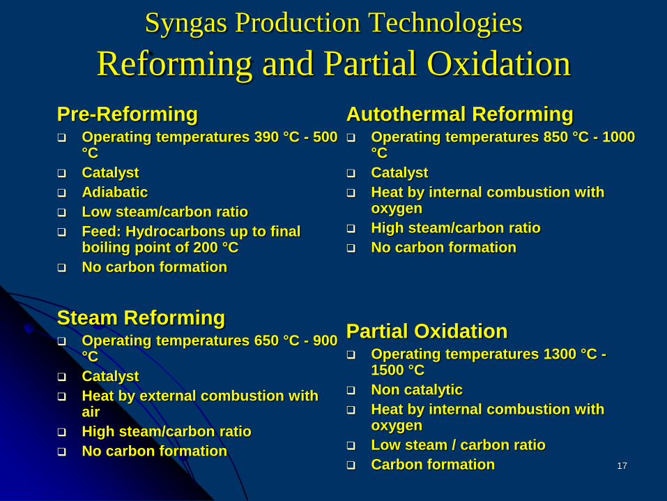
Syngas Production Technologies
Reforming and Partial Oxidation
Pre-Reforming Operating temperatures 390 °C - 500
°C
Catalyst
Adiabatic
Low steam/carbon ratio
Feed: Hydrocarbons up to final boiling point of 200 °C
No carbon formation
Steam Reforming Operating temperatures 650 °C - 900
°C
Catalyst
Heat by external combustion with air
High steam/carbon ratio
No carbon formation
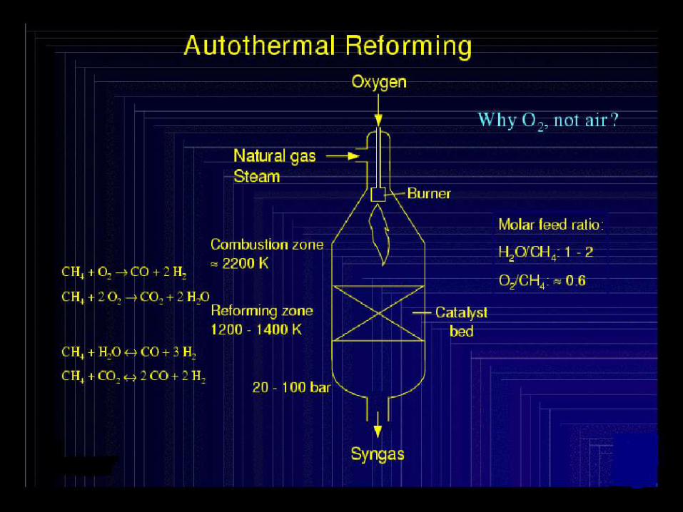
Autothermal Reforming Operating temperatures 850 °C - 1000
°C
Catalyst
Heat by internal combustion with oxygen
High steam/carbon ratio
No carbon formation
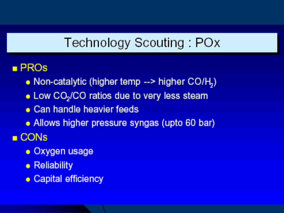
Partial Oxidation Operating temperatures 1300 °C -
1500 °C
Non catalytic
Heat by internal combustion with oxygen
Low steam / carbon ratio
Carbon formation
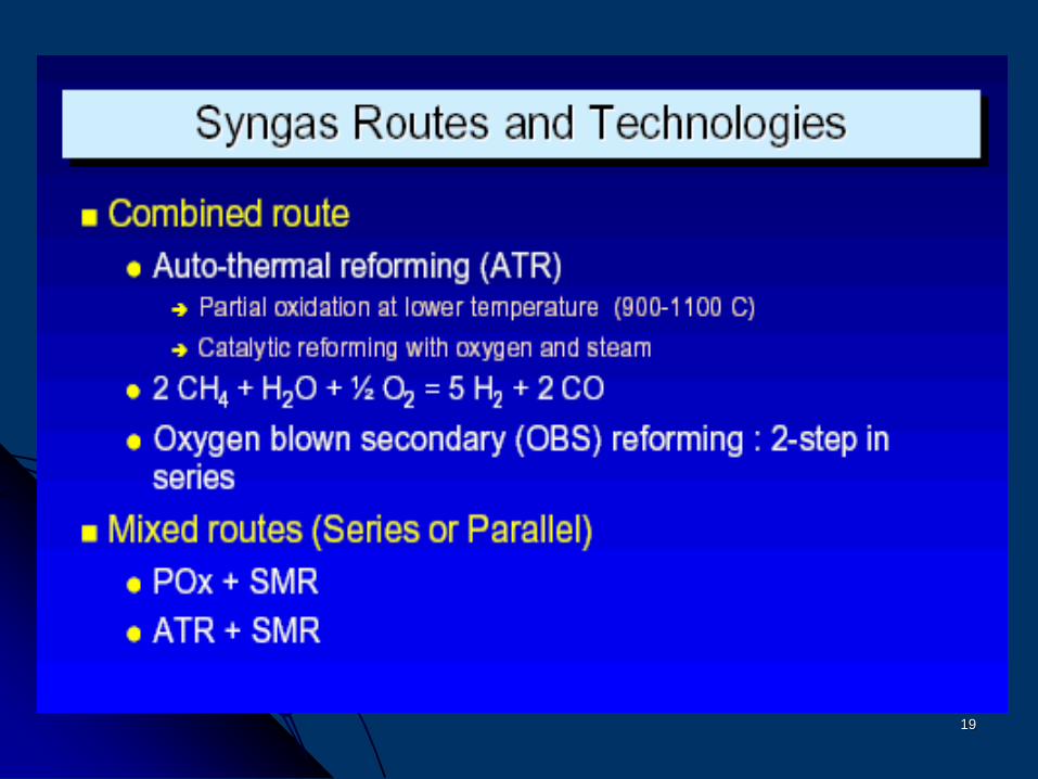
18
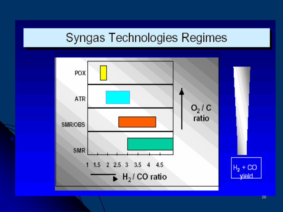
19
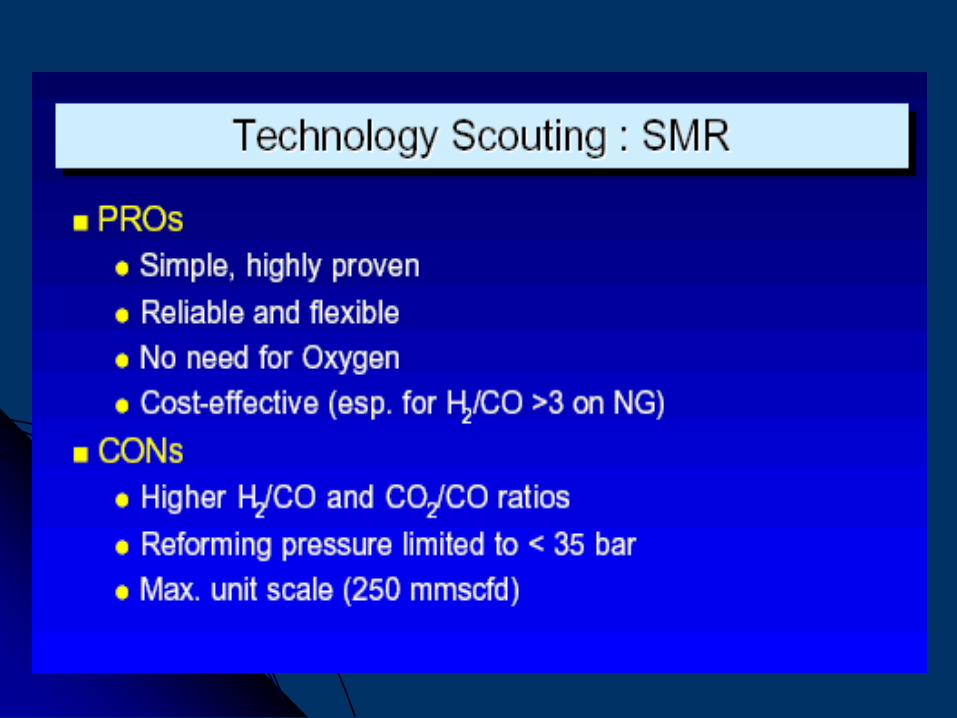
20
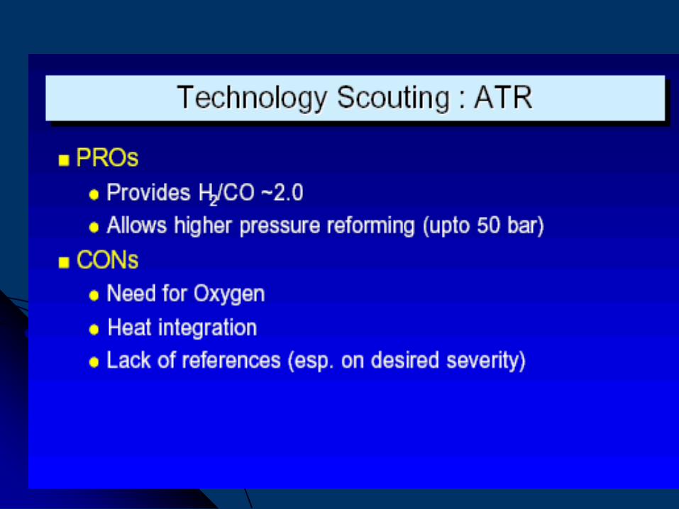
21
22
23
24
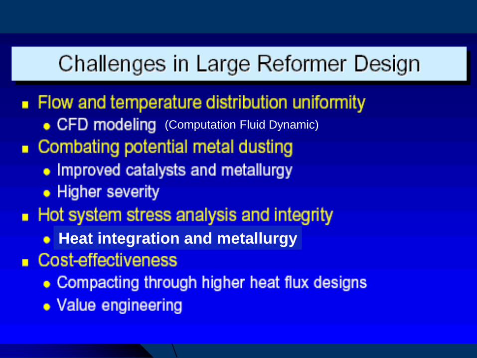
(Computation Fluid Dynamic)
Heat integration and metallurgy
25
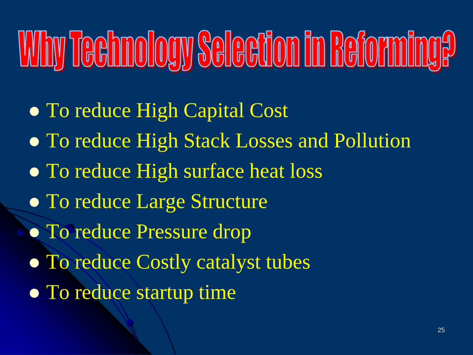
To reduce High Capital Cost
To reduce High Stack Losses and Pollution
To reduce High surface heat loss
To reduce Large Structure
To reduce Pressure drop
To reduce Costly catalyst tubes
To reduce startup time
26
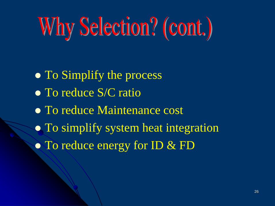
To Simplify the process
To reduce S/C ratio
To reduce Maintenance cost
To simplify system heat integration
To reduce energy for ID & FD
27
Catalyst
Catalyst tube material
Air pre-heater (Modification)
Pre-Reformer
Reforming Process (heat integration)
Design
28
High activity
More surface area
Low pressure drop
High physical strength
More stable for poisons
29
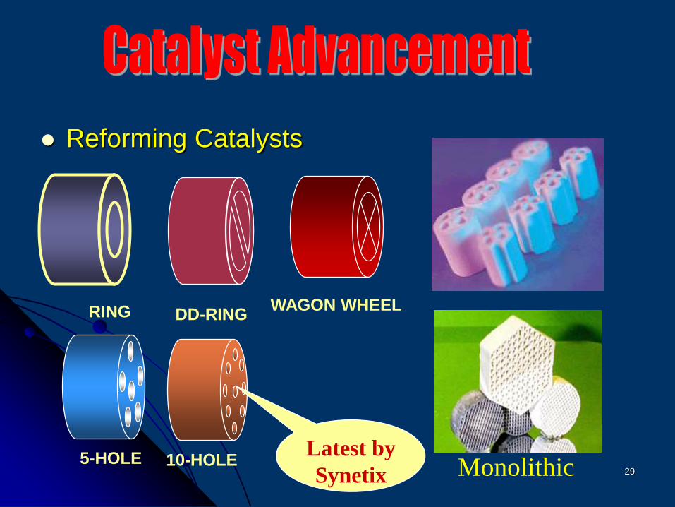
Reforming Catalysts
RING WAGON WHEEL
5-HOLE
DD-RING
Monolithic10-HOLELatest by
Synetix
30
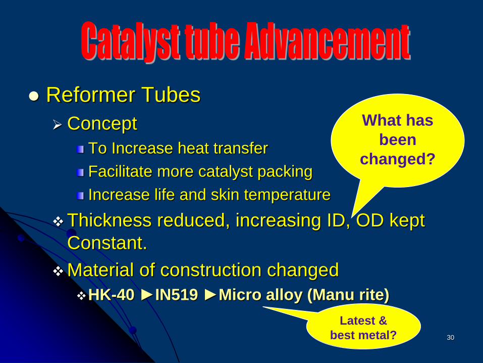
Reformer Tubes
Concept
To Increase heat transfer
Facilitate more catalyst packing
Increase life and skin temperature
Thickness reduced, increasing ID, OD kept
Constant.
Material of construction changed
HK-40 ►IN519 ►Micro alloy (Manu rite)
What has
been
changed?
Latest &
best metal?
31
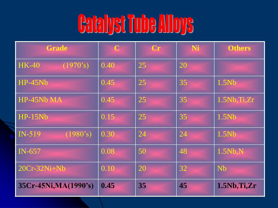
Grade C Cr Ni Others
HK-40 (1970’s) 0.40 25 20
HP-45Nb 0.45 25 35 1.5Nb
HP-45Nb MA 0.45 25 35 1.5Nb,Ti,Zr
HP-15Nb 0.15 25 35 1.5Nb
IN-519 (1980’s) 0.30 24 24 1.5Nb
IN-657 0.08 50 48 1.5Nb,N
20Cr-32Ni+Nb 0.10 20 32 Nb
35Cr-45Ni,MA(1990’s) 0.45 35 45 1.5Nb,Ti,Zr
32
Basic reason is to reduce heat loss
through Primary Reformer stack
To save Fuel and proper combustion.
ID fan load is reduced.
33
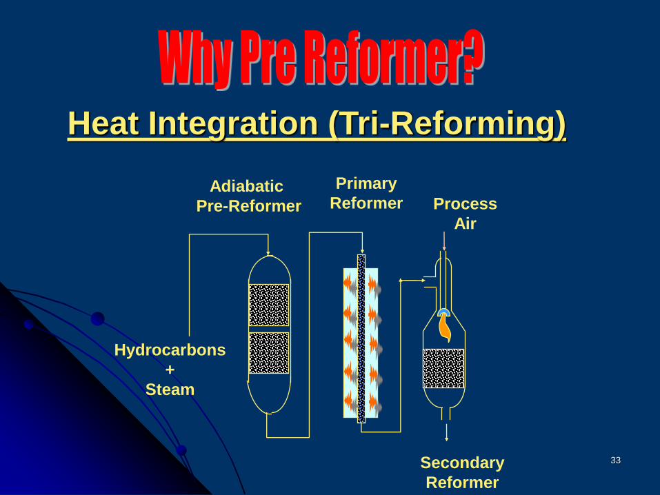
Process
Air
Hydrocarbons
+
Steam
Adiabatic
Pre-Reformer
Primary
Reformer
Secondary
Reformer
Heat Integration (Tri-Reforming)
34
Feed Stock flexibility (Higher hydrocarbons)
Reduced Load on Primary Reformer
Improvement of Primary Reformer catalyst
life
Lower tube skin temperature
As guard for Primary Reformer Catalyst
Easy replacement of catalyst (without
complete plant shut down)
35
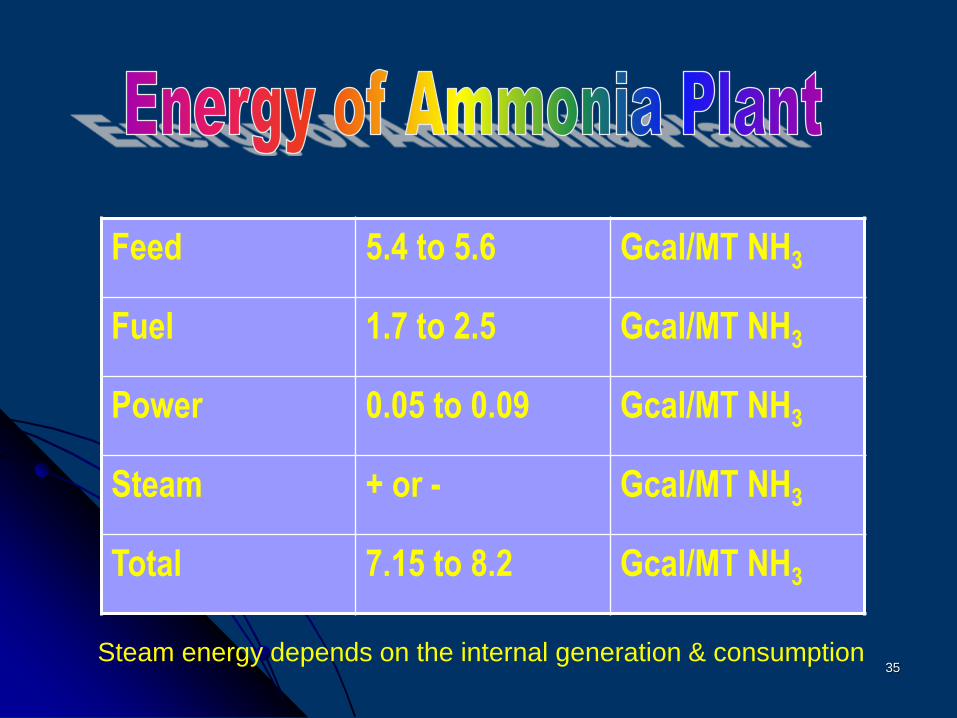
Feed 5.4 to 5.6 Gcal/MT NH3
Fuel 1.7 to 2.5 Gcal/MT NH3
Power 0.05 to 0.09 Gcal/MT NH3
Steam + or - Gcal/MT NH3
Total 7.15 to 8.2 Gcal/MT NH3
Steam energy depends on the internal generation & consumption
36
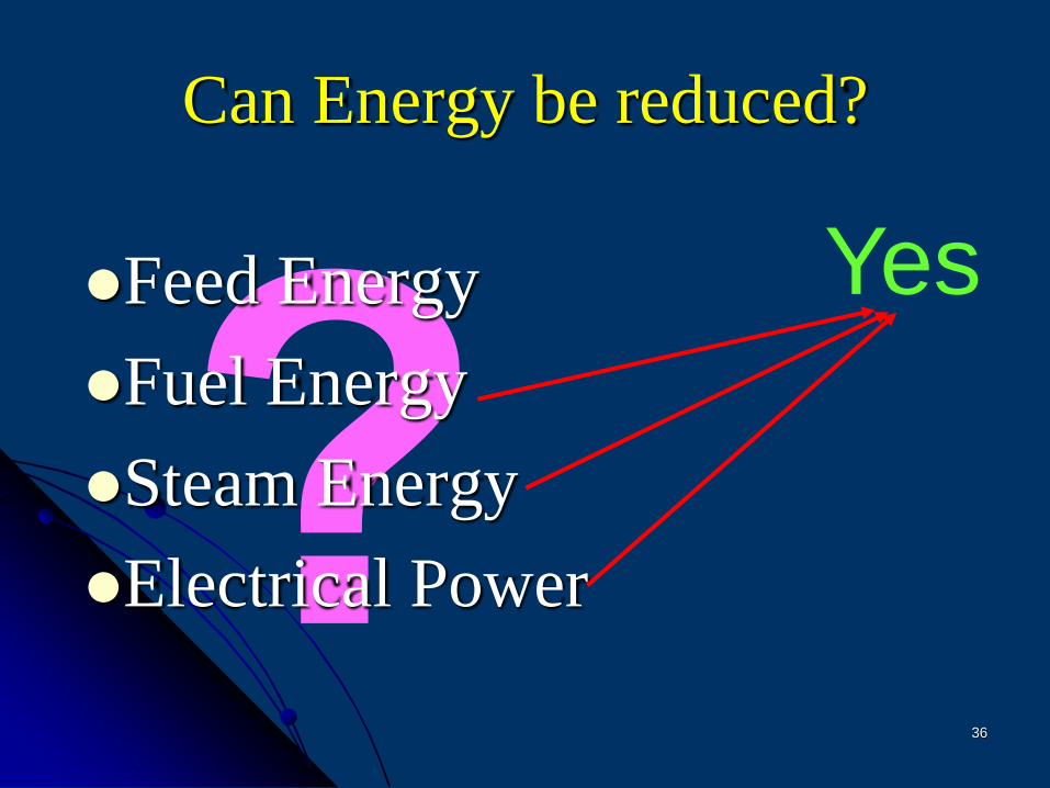
Can Energy be reduced?
Feed Energy
Fuel Energy
Steam Energy
Electrical Power
Yes
37
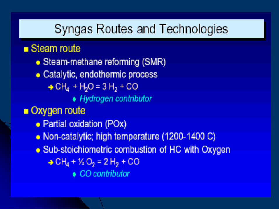
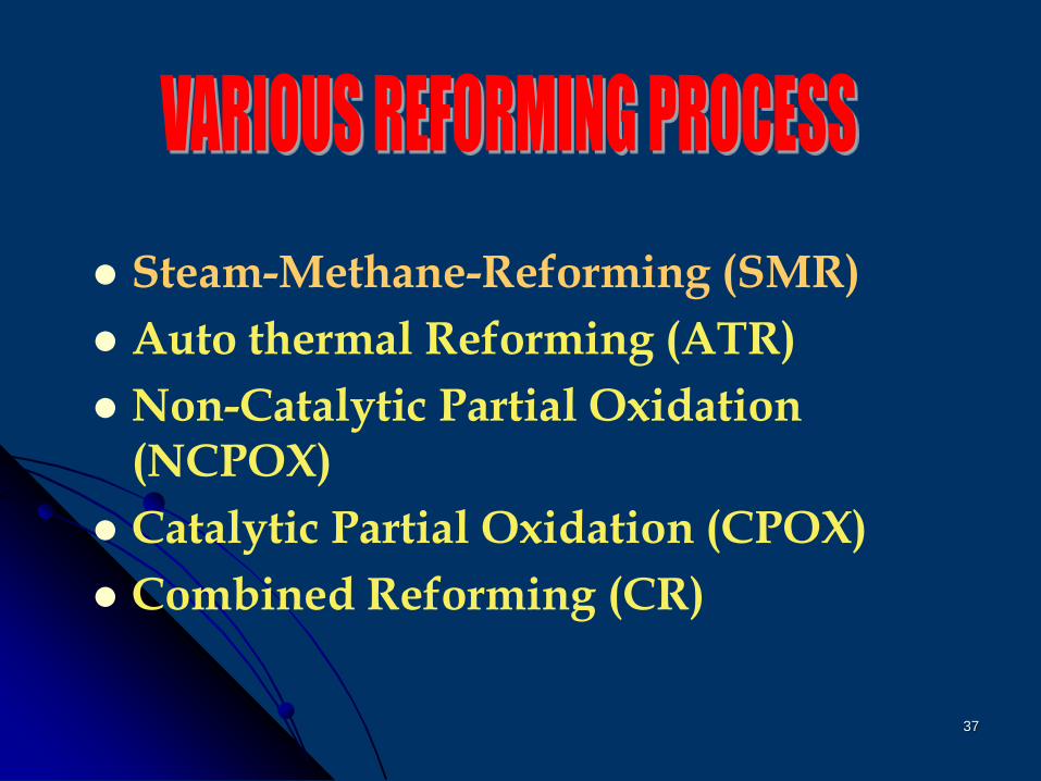
Steam-Methane-Reforming (SMR)
Auto thermal Reforming (ATR)
Non-Catalytic Partial Oxidation (NCPOX)
Catalytic Partial Oxidation (CPOX)
Combined Reforming (CR)
38
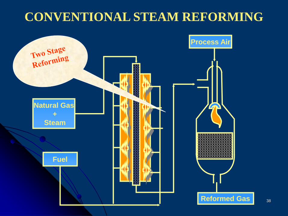
CONVENTIONAL STEAM REFORMING
Process Air
Natural Gas
+
Steam
Reformed Gas
Fuel
39
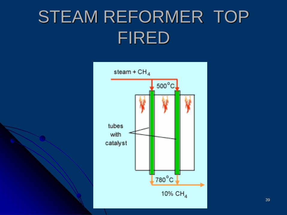
STEAM REFORMER TOP
FIRED
40
41
Steam-Methane Reforming
Advancements
Reduction in numbers of catalyst tubes
Primary Reformer size reduction
Elimination of FD fan
Dual fuel firing system
To improve combustion, improved burner designs
42
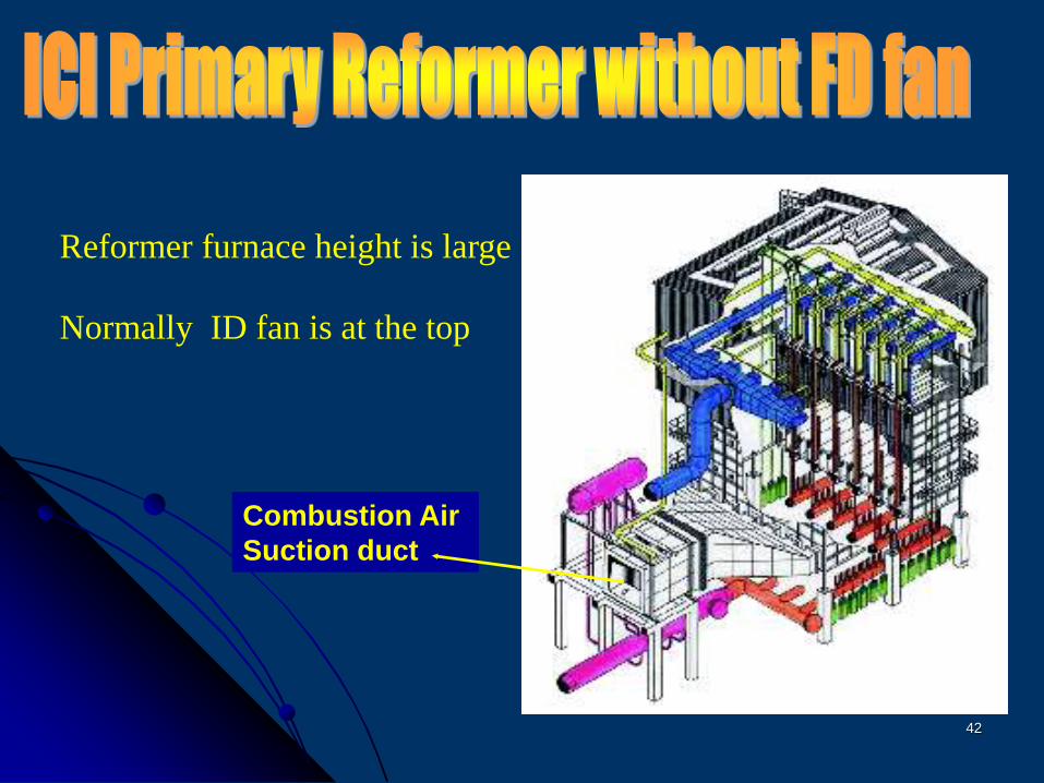
Combustion Air
Suction duct
Reformer furnace height is large
Normally ID fan is at the top
43
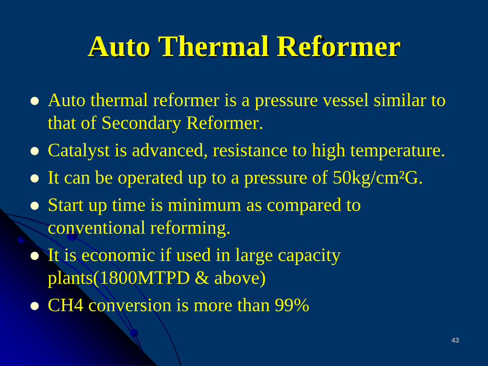
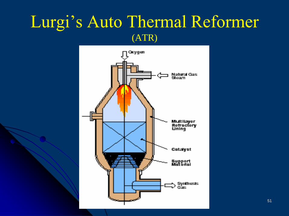
Auto Thermal Reformer
Auto thermal reformer is a pressure vessel similar to
that of Secondary Reformer.
Catalyst is advanced, resistance to high temperature.
It can be operated up to a pressure of 50kg/cm²G.
Start up time is minimum as compared to
conventional reforming.
It is economic if used in large capacity
plants(1800MTPD & above)
CH4 conversion is more than 99%
44
45
Auto Thermal Reforming Route
ATR technology is offered by three Process Licensors
M/s Lurgi, Germany
M/s KBR, USA
M/s HTAS, Denmark
46
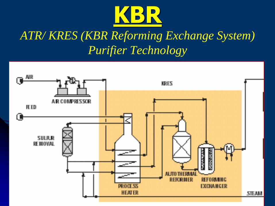
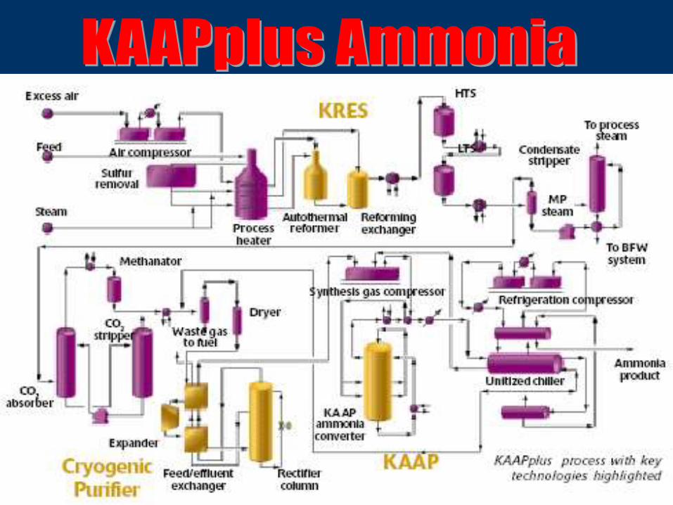
KBR ATR/ KRES (KBR Reforming Exchange System)
Purifier Technology
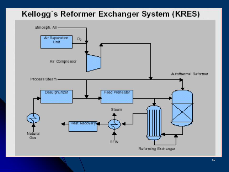
47
48
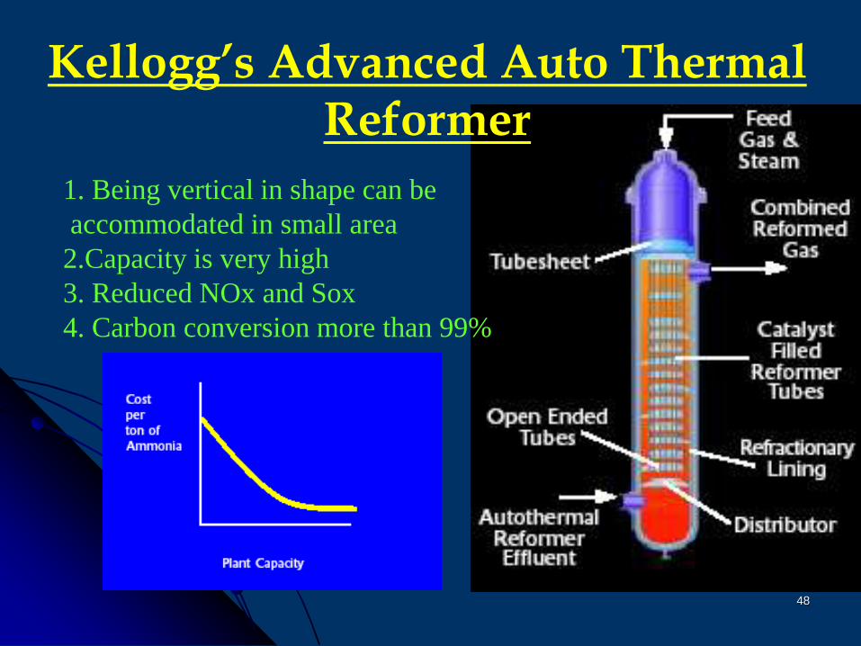
Kellogg’s Advanced Auto Thermal Reformer
1. Being vertical in shape can be
accommodated in small area
2.Capacity is very high
3. Reduced NOx and Sox
4. Carbon conversion more than 99%
49
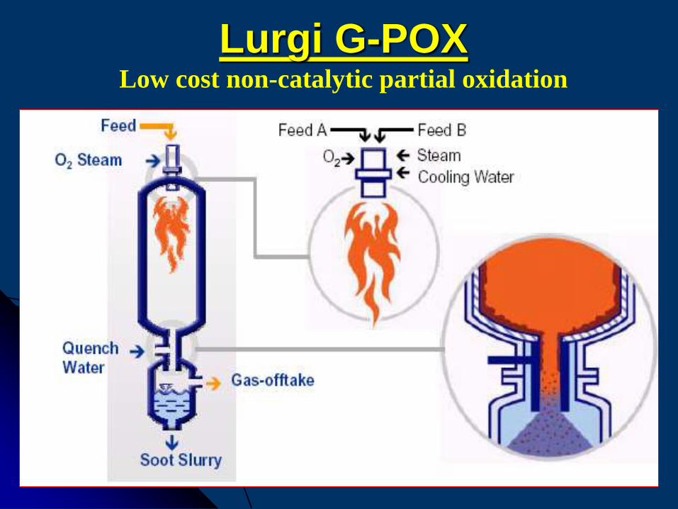
Lurgi G-POX Low cost non-catalytic partial oxidation
50
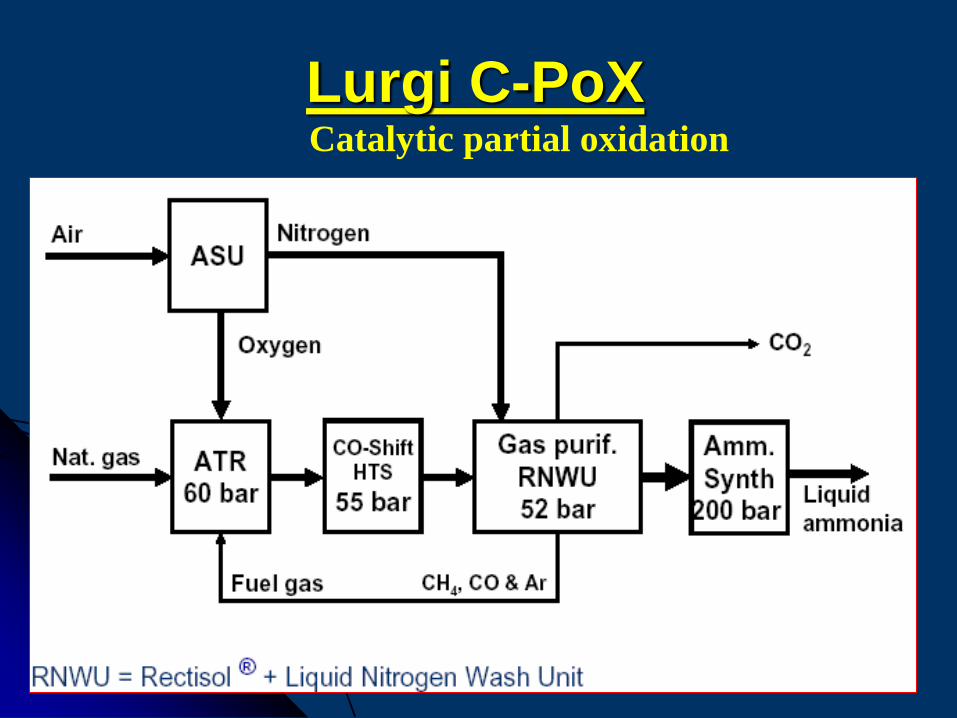
Lurgi C-PoXCatalytic partial oxidation
51
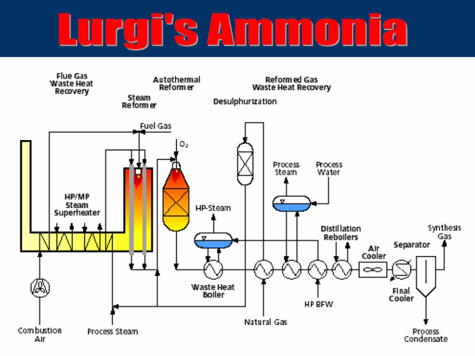
Lurgi’s Auto Thermal Reformer (ATR)
52
HTASThe key elements of the technology are the design
of the burner, the catalyst formulation, and
refinement of the operating conditions.
Topsøe’s proprietary burner design has been
developed on the basis of computational fluid
dynamics, hydraulic simulation, pilot plant
testing, and feedback from industrial operation.
53
Secondary Reformer
Critical parts
Burner (gun)
Catalyst and top bricks
Insulation material
Material of construction
54
Combined Reforming
In this process the heat generated in
Secondary Reformer has been used in
Primary Reformer
Type of Combined Reformers
Gas Heater Reforming (GHR)
Heat Exchange Reforming (HER)
Heat Integrated Reforming (HIR)
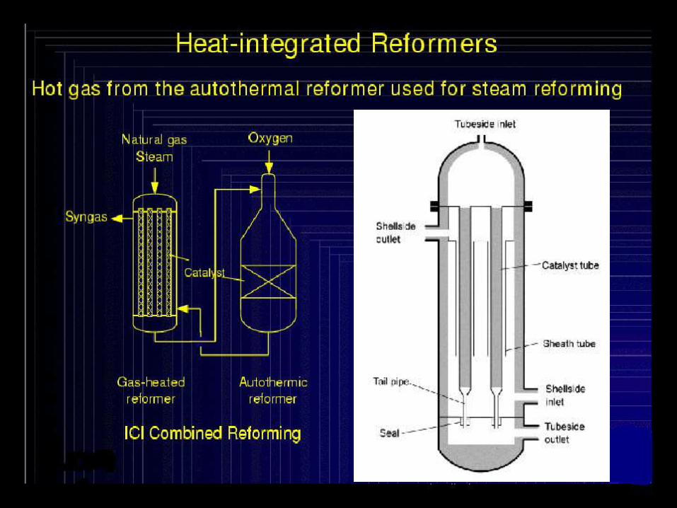
55
56
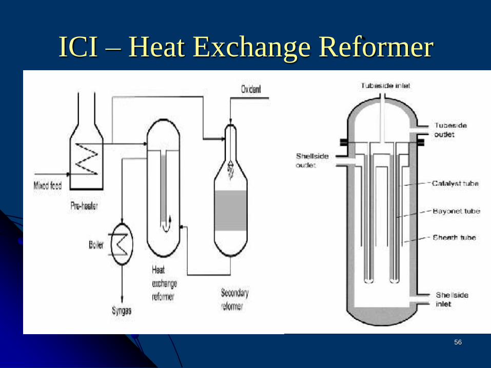
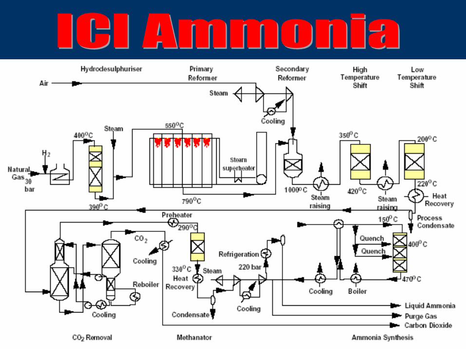
ICI – Heat Exchange Reformer
57
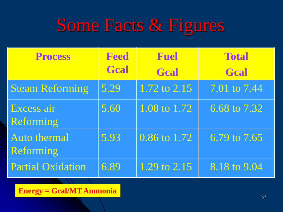
Some Facts & Figures
Process Feed
Gcal
Fuel
Gcal
Total
Gcal
Steam Reforming 5.29 1.72 to 2.15 7.01 to 7.44
Excess air
Reforming
5.60 1.08 to 1.72 6.68 to 7.32
Auto thermal
Reforming
5.93 0.86 to 1.72 6.79 to 7.65
Partial Oxidation 6.89 1.29 to 2.15 8.18 to 9.04
Energy = Gcal/MT Ammonia
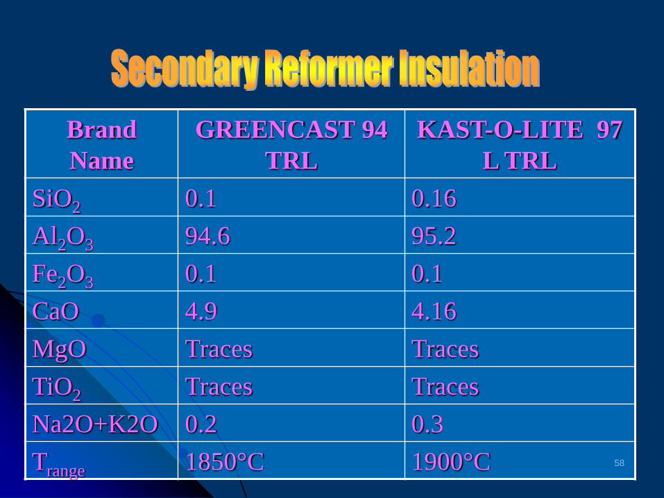
58
Brand
Name
GREENCAST 94
TRL
KAST-O-LITE 97
L TRL
SiO2 0.1 0.16
Al2O3 94.6 95.2
Fe2O3 0.1 0.1
CaO 4.9 4.16
MgO Traces Traces
TiO2 Traces Traces
Na2O+K2O 0.2 0.3
Trange 1850°C 1900°C
59
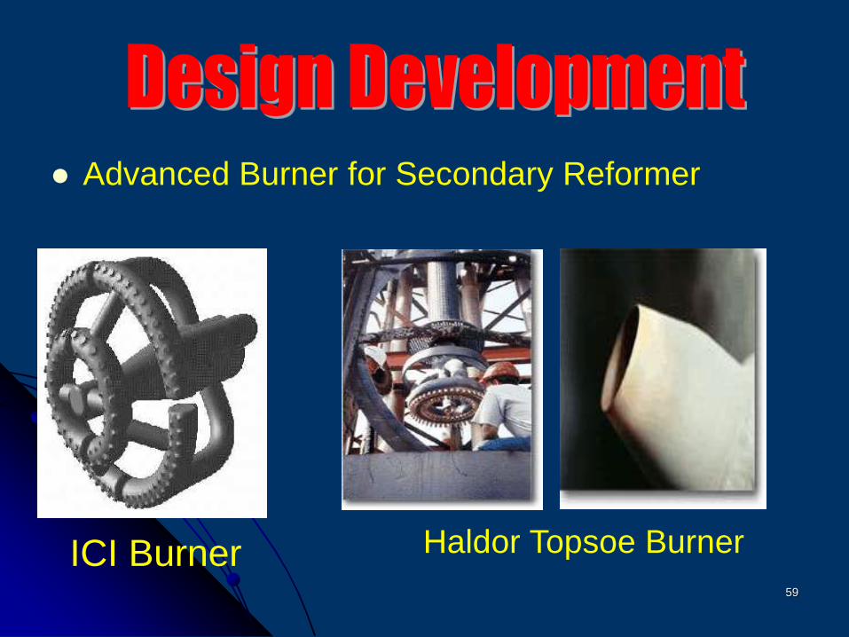
Advanced Burner for Secondary Reformer
ICI Burner Haldor Topsoe Burner
60
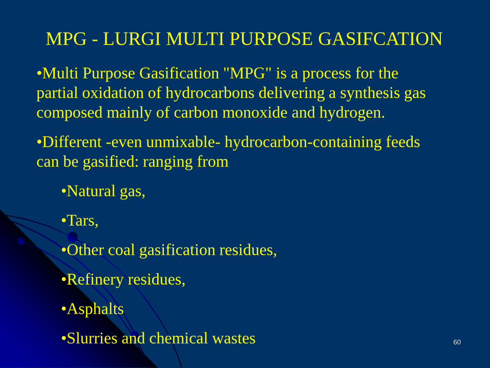
MPG - LURGI MULTI PURPOSE GASIFCATION
•Multi Purpose Gasification "MPG" is a process for the
partial oxidation of hydrocarbons delivering a synthesis gas
composed mainly of carbon monoxide and hydrogen.
•Different -even unmixable- hydrocarbon-containing feeds
can be gasified: ranging from
•Natural gas,
•Tars,
•Other coal gasification residues,
•Refinery residues,
•Asphalts
•Slurries and chemical wastes
61
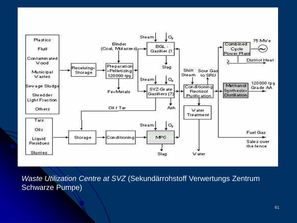
Waste Utilization Centre at SVZ (Sekundärrohstoff Verwertungs Zentrum
Schwarze Pumpe)
62
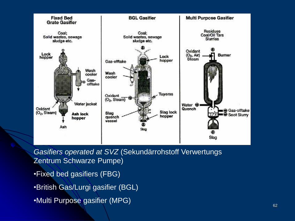
Gasifiers operated at SVZ (Sekundärrohstoff Verwertungs
Zentrum Schwarze Pumpe)
•Fixed bed gasifiers (FBG)
•British Gas/Lurgi gasifier (BGL)
•Multi Purpose gasifier (MPG)
63
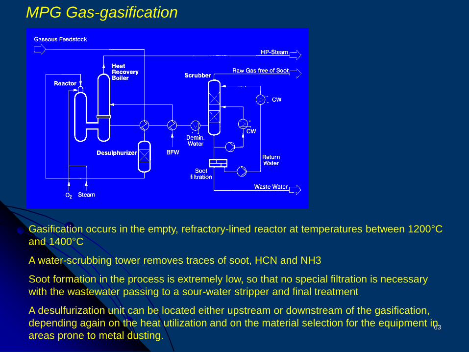
MPG Gas-gasification
Gasification occurs in the empty, refractory-lined reactor at temperatures between 1200°C
and 1400°C
A water-scrubbing tower removes traces of soot, HCN and NH3
Soot formation in the process is extremely low, so that no special filtration is necessary
with the wastewater passing to a sour-water stripper and final treatment
A desulfurization unit can be located either upstream or downstream of the gasification,
depending again on the heat utilization and on the material selection for the equipment in
areas prone to metal dusting.
64
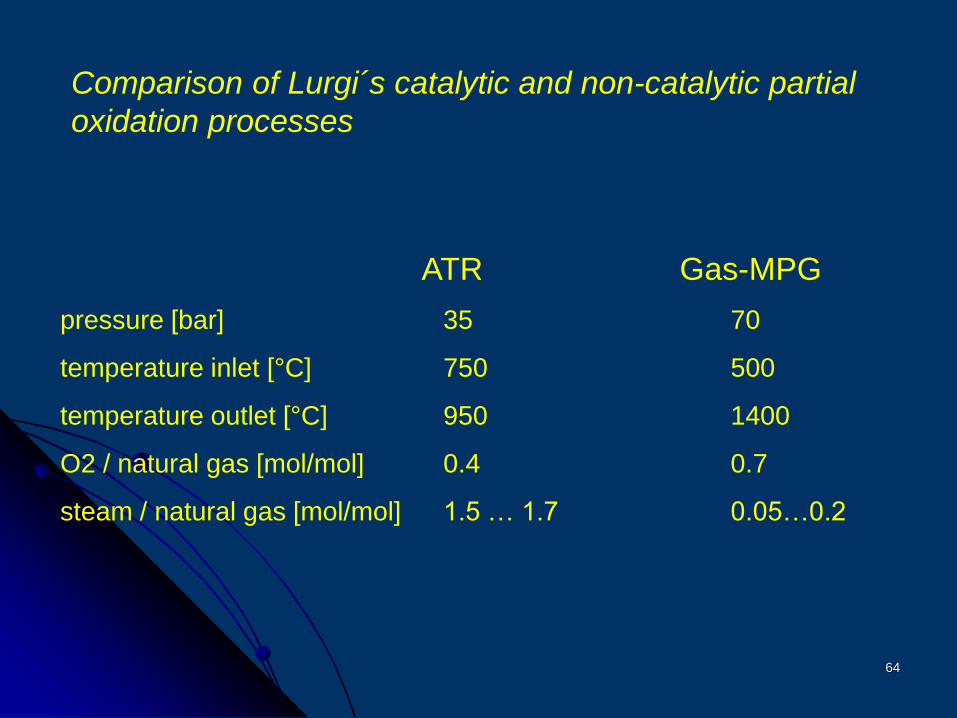
ATR Gas-MPG
pressure [bar] 35 70
temperature inlet [°C] 750 500
temperature outlet [°C] 950 1400
O2 / natural gas [mol/mol] 0.4 0.7
steam / natural gas [mol/mol] 1.5 … 1.7 0.05…0.2
Comparison of Lurgi´s catalytic and non-catalytic partial
oxidation processes
65
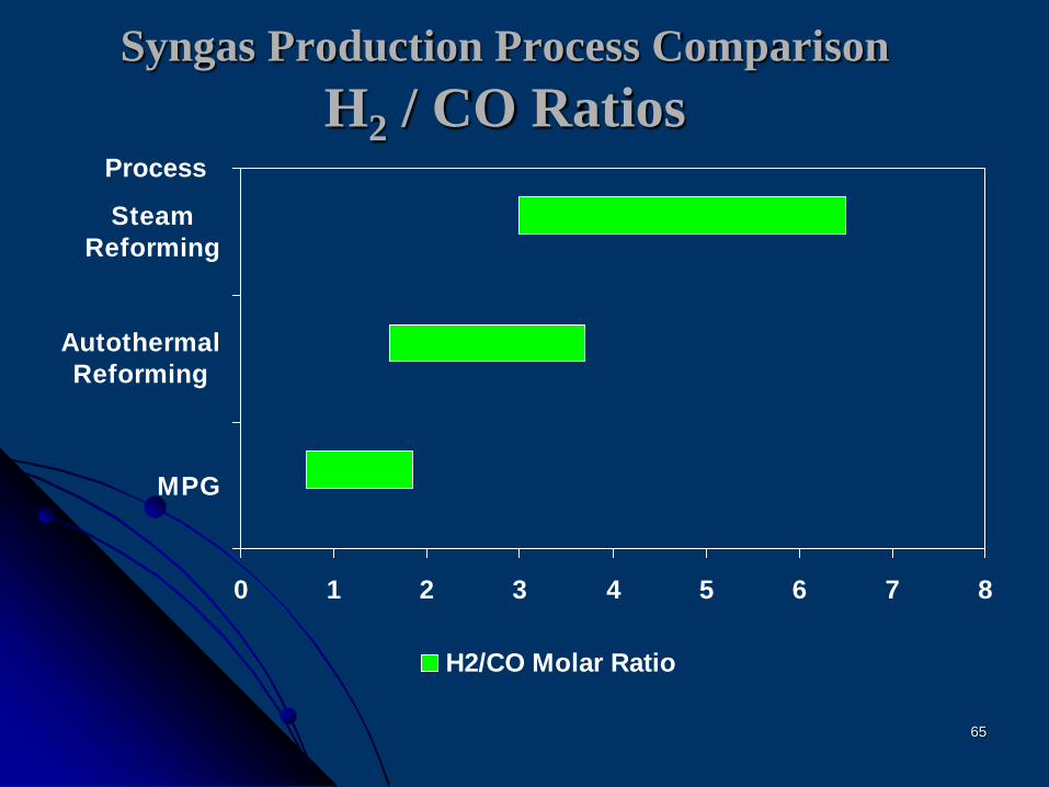
0 1 2 3 4 5 6 7 8
MPG
Autothermal
Reforming
Steam
Reforming
H2/CO Molar Ratio
Process
Syngas Production Process Comparison
H2 / CO Ratios
66
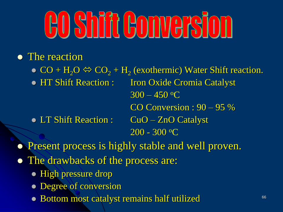
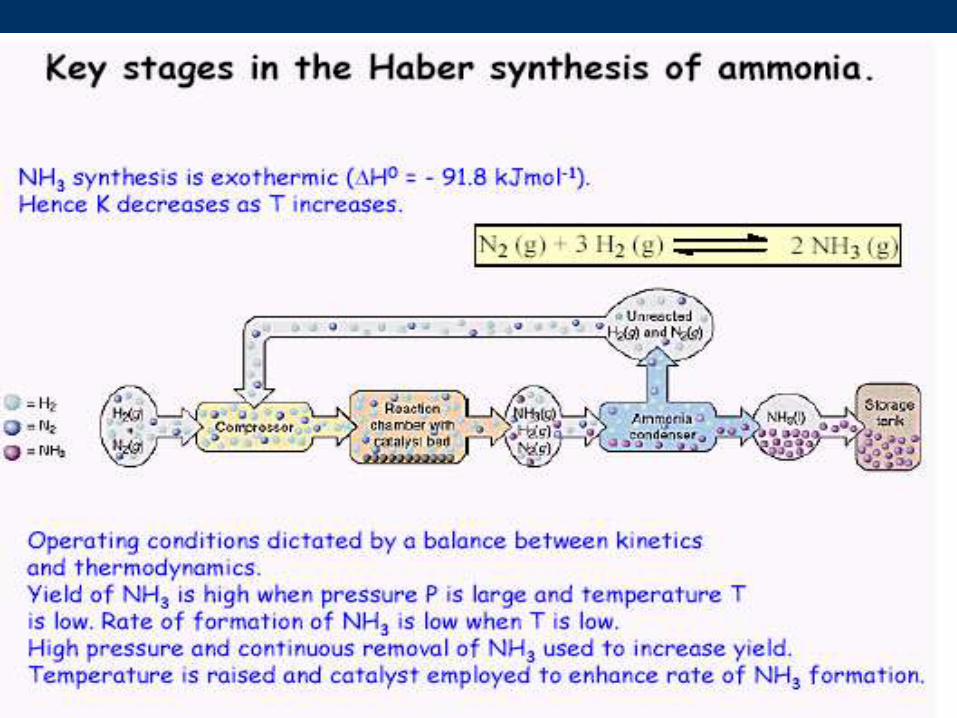
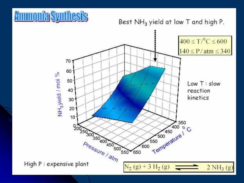
The reaction
CO + H2O CO2 + H2 (exothermic) Water Shift reaction.
HT Shift Reaction : Iron Oxide Cromia Catalyst
300 – 450 oC
CO Conversion : 90 – 95 %
LT Shift Reaction : CuO – ZnO Catalyst
200 - 300 oC
Present process is highly stable and well proven.
The drawbacks of the process are:
High pressure drop
Degree of conversion
Bottom most catalyst remains half utilized
67
Isothermal reactors were tested to improve the
CO conversion but failed.
Reasons
High pressure drop
Mechanical failure of inter bed exchangers
What is successful ?
68
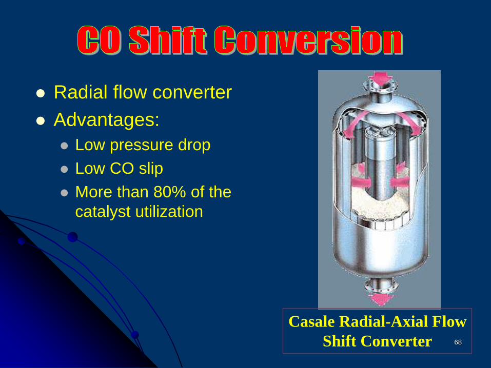
Radial flow converter
Advantages:
Low pressure drop
Low CO slip
More than 80% of the
catalyst utilization
Casale Radial-Axial Flow
Shift Converter
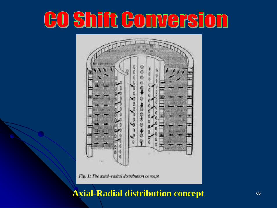
69Axial-Radial distribution concept
70
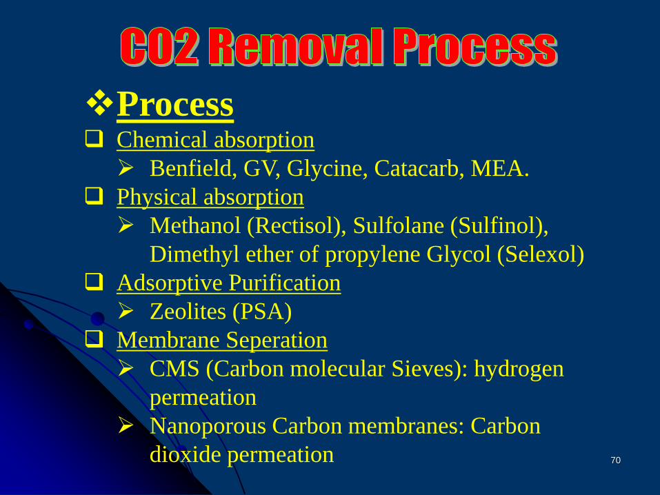
Process Chemical absorption
Benfield, GV, Glycine, Catacarb, MEA.
Physical absorption
Methanol (Rectisol), Sulfolane (Sulfinol),
Dimethyl ether of propylene Glycol (Selexol)
Adsorptive Purification
Zeolites (PSA)
Membrane Seperation
CMS (Carbon molecular Sieves): hydrogen
permeation
Nanoporous Carbon membranes: Carbon
dioxide permeation
71
72
73
74
75
76
Advancements Why?
High loop pressure
Low conversion per path
Compressor Recycle stage Efficiency Low
High pressure drop across the loop
High Compression power
77
Advancements What?
Improved catalyst activity
Reduce pressure +drop
Increase conversion per path
Reduce synthesis gas compressor size and
increase efficiency.
78
Synthesis gas purification (eliminate CH4, Ar)/Reduction in gas volume
Latest Ruthenium catalyst (Reduced loop pressure)
Using catalyst in multi-beds with inter-stage cooler.
Drying and cooling synthesis gas
Eliminate inter cooler separators (or make compact)
Improved design
79
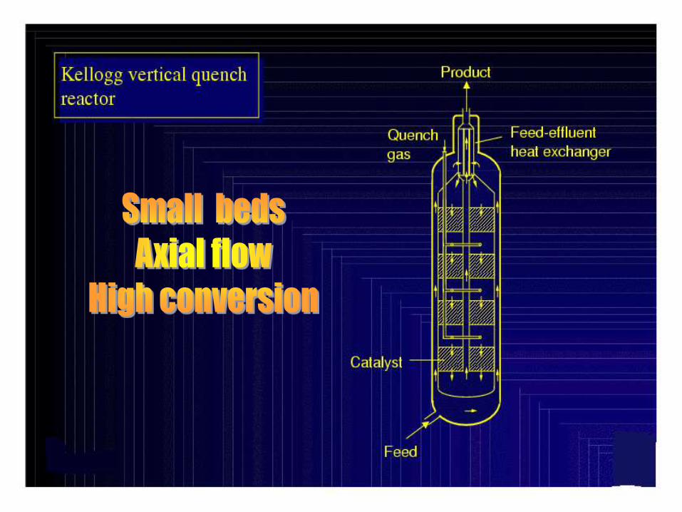
Haldor Topsoe
Kellogg (KRES)
Kellogg-Braun-Root (KAAP, KBR)
Foster Wheeler
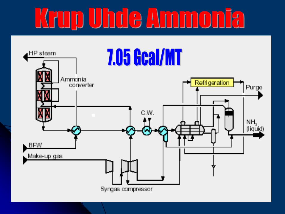
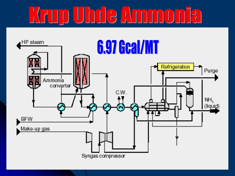
Krupp-Uhde
ICI, Leading Concept Ammonia (LCA)
Most widly used Technologies
80
81
82
83
84
85
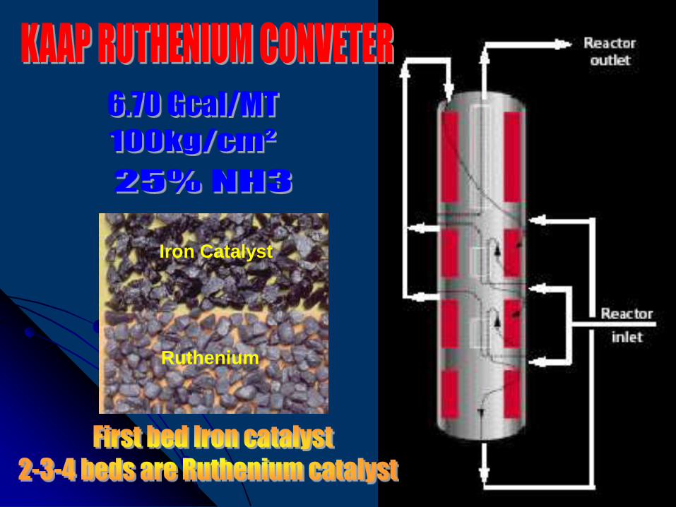
Iron Catalyst
Ruthenium
86
87
88
89
90
91
92
93
Ammonia Casale Axial Radial
Converter:
Annular top bed is left open at the top to permit a
part of the gas flow radially through the catalyst
bed.
The Brown & Root Braun Adiabatic
Converter:
Two adiabatic converters in series each
containing a single catalyst bed.
94
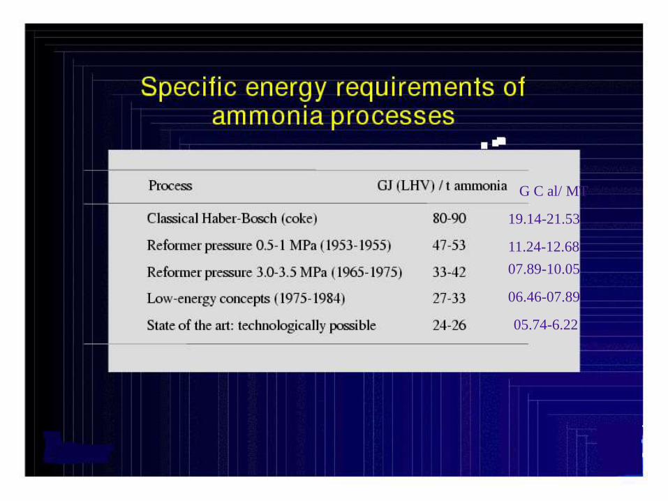
19.14-21.53
G C al/ MT
11.24-12.68
07.89-10.05
06.46-07.89
05.74-6.22
95