variable displacement pump a7vo 92 202/07 · pdf filevariable displacement pump a7vo series 6,...
TRANSCRIPT
1
5100 psi(350 bar)Nominal Pressure Peak Pressure
5800 psi(400 bar)
RA92 202/07.95
metric
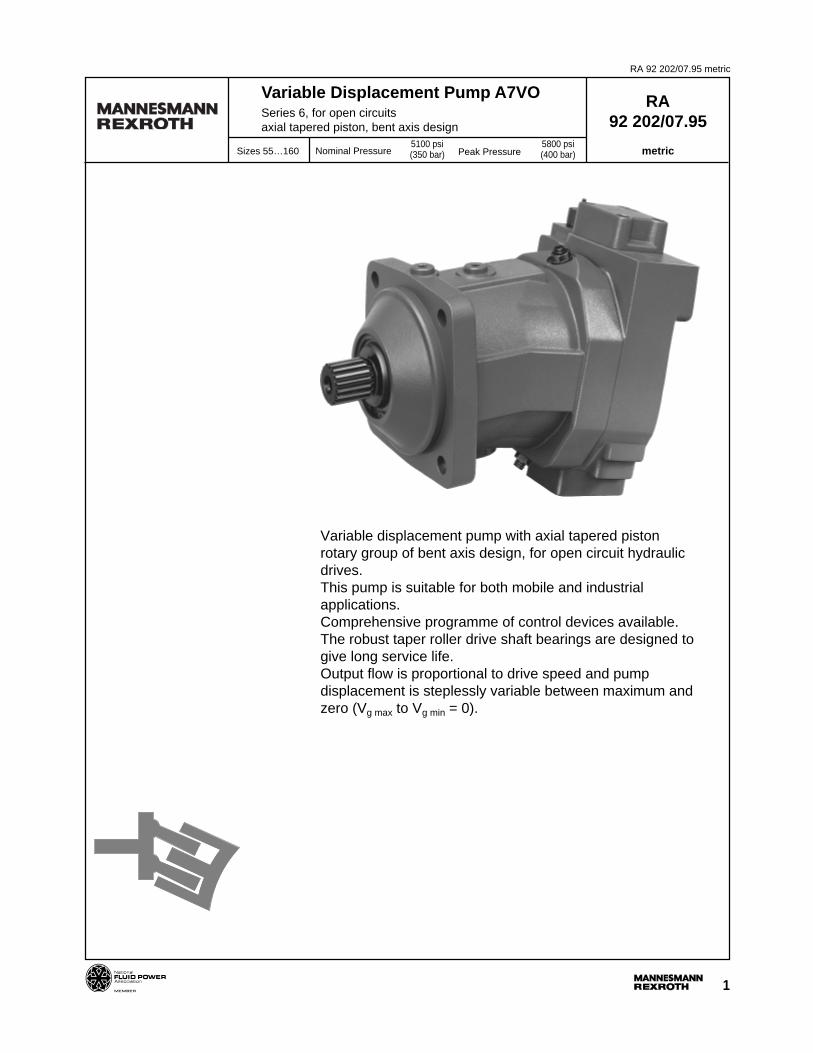
Variable Displacement Pump A7VOSeries 6, for open circuitsaxial tapered piston, bent axis design
Sizes 55…160
Variable displacement pump with axial tapered pistonrotary group of bent axis design, for open circuit hydraulicdrives.This pump is suitable for both mobile and industrialapplications.Comprehensive programme of control devices available.The robust taper roller drive shaft bearings are designed togive long service life.Output flow is proportional to drive speed and pumpdisplacement is steplessly variable between maximum andzero (Vg max to Vg min = 0).
RA 92 202/07.95 metric
2-3
Variable Displacement Pump A7VO
RA 92 202/07.95 metric
H1 hydr. stroke limiter ∆p = 365 psi (25 bar), neg. control
H2 hydr. stroke limiter ∆p = 365 psi (25 bar), pos. control
H5 hydr. stroke limiter ∆p = 145 psi (10 bar), neg. control
H6 hydr. stroke limiter ∆p = 145 psi (10 bar), pos. control
U electrical stroke limiter
Hydraulic controlpilot pressure dependent
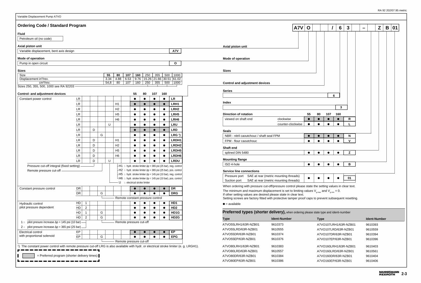
Ordering Code / Standard Program
Fluid
Petroleum oil (no code)
Axial piston unit
Variable displacement, bent axis design A7V
Mode of operation
Pump in open circuit O
SizesSize 55 80 107 160 250 355 500 1000Displacement in3/rev. 3.34 4.88 6.53 9.76 15.26 21.66 30.51 61.02
cm3/rev. 54,8 80 107 160 250 355 500 1000Sizes 250, 355, 500, 1000 see RA 92203
Control- and adjustment devices 55 80 107 160
Constant power control LR LR
LR H1 LRH1
LR H2 LRH2
LR H5 LRH5
LR H6 LRH6
LR U LRU
LR D LRD
LR G LRG 1)
LR D H1 LRDH1
LR D H2 LRDH2
LR D H5 LRDH5
LR D H6 LRDH6
LR D U LRDU
Pressure cut-off integral (fixed setting)
Remote pressure cut-off
Constant pressure control DR DR
DR G DRG
Remote constant pressure control
HD 1 HD1
HD 2 HD2
HD 1 G HD1G
HD 2 G HD2G
1 pilot presure increase ∆p = 145 psi (10 bar) Remote pressure cut-off
2 pilot presure increase ∆p = 365 psi (25 bar)
EP EP
EP G EPG
Remote pressure cut-off1) The constant power control with remote pressure cut-off LRG is also available with hydr. or electrical stroke limiter (e. g. LRGH1).
= Preferred program (shorter delivery times)
Electrical controlwith proportional solenoid
Type Ident-Number
A7VO55LRH1/63R-NZB01 9610373
A7VO55LRD/63R-NZB01 9610555
A7VO55DR/63R-NZB01 9610374
A7VO55EP/63R-NZB01 9610376
A7VO80LRH1/63R-NZB01 9610383
A7VO80LRD/63R-NZB01 9610557
A7VO80DR/63R-NZB01 9610384
A7VO80EP/63R-NZB01 9610386
Preferred types (shorter delivery), when ordering please state type and ident-number
Type Ident-Number
A7VO107LRH1/63R-NZB01 9610393
A7VO107LRD/63R-NZB01 9610559
A7VO107DR/63R-NZB01 9610394
A7VO107EP/63R-NZB01 9610396
A7VO160LRH1/63R-NZB01 9610403
A7VO160LRD/63R-NZB01 9610561
A7VO160DR/63R-NZB01 9610404
A7VO160EP/63R-NZB01 9610406
A7V O / 6 3 – Z B 01
Axial piston unit
Mode of operation
Sizes
Control and adjustment devices
Series
6
Index
3
Direction of rotation 55 80 107 160
viewed on shaft end clockwise R
counter-clockwise L
Seals
NBR - nitril caoutchouc / shaft seal FPM N
FPM - flour caoutchouc V
Shaft end
splined DIN 5480 Z
Mounting flange
ISO 4-hole B
Service line connections
Pressure port SAE at rear (metric mounting threads)01
Suction port SAE at rear (metric mounting threads)
When ordering with pressure cut-off/pressure control please state the setting values in clear text.
The minimum and maximum displacement is set to limiting values Vg max and Vg min = 0.If other setting values are desired please state in clear text.Setting screws are factory fitted with protective tamper proof caps to prevent subsequent resetting.
= available
RA 92 202/07.95 metric
4
Variable Displacement Pump A7VO
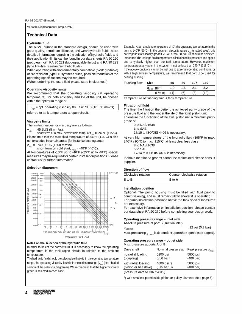
Example: At an ambient temperature of X°, the operating temperature in thetank is 140°F (60°C). In the optimum viscosity range ν
opt (shaded area), this
corresponds to viscosity grades VG 46 or VG 68, VG 68 should be selected.Important: The leakage fluid temperature is influenced by pressure and speedand is typically higher than the tank temperature. However, maximumtemperature at any point in the system must be less than 240°F (115°C).If the above conditions cannot be met due to extreme operating conditions, orwith a high ambient temperature, we recommend that port U be used forbearing flushing.
Flushing flow Size 55 80 107 160
qV Sp gpm 1,0 1,6 2,1 3,2
(L/min) (4) (6) (8) (12)
Temperature of flushing fluid ≤ tank temperature
Filtration of fluidThe finer the filtration the better the achieved purity grade of thepressure fluid and the longer the life of the axial piston unit.To ensure the functioning of the axial piston unit a minimum puritygrade of:
9 to NAS 16386 to SAE18/15 to ISO/DIS 4406 is necessary.
At very high temperatures of the hydraulic fluid (195°F to max.240°F / 90°C to max. 115°C) at least cleanless class
8 to NAS 16385 to SAE17/14 to ISO/DIS 4406 is necessary.
If above mentioned grades cannot be maintained please consultsupplier.
Direction of flow
Clockwise rotation Counter-clockwise rotation
S to B S to A
Installation positionOptional. The pump housing must be filled with fluid prior tocommissioning, and must remain full whenever it is operating.For pump installation positions above the tank special measuresare necessary.For extensive information on installation position, please consultour data sheet RA 90 270 before completing your design work.
Operating pressure range – inlet sideAbsolute pressure at port S (suction inlet)pabs min ______________________________ 12 psi (0,8 bar)
Max. pressure pabs max is dependent upon shaft speed (see page 5).
Operating pressure range – outlet sideMax. pressure at ports A or B
Drive shaft Nominal pressure pn Peak pressure pmax
no radial loading 5100 psi 5800 psi(coupling) (350 bar) (400 bar)
with radial loading 4600 psi 1) 5800 psi(pinion or belt drive) (315 bar 1)) (400 bar)
(pressure data to DIN 24312)
1) wtih smallest permissible pinion or pulley diameter (see page 5).
Technical Data
Hydraulic fluidThe A7VO pumps in the standard design, should be used withgood quality, petroleum oil based, anti-wear hydraulic fluids. Moredetailed information regarding the selection of hydraulic fluids andtheir application limits can be found in our data sheets RA 90 220(petroleum oil), RA 90 221 (biodegradable fluids) and RA 90 223(type HF–fire resistant/synthetic fluids).When operating with environmentally compatible (biodegradable)or fire resistant (type HF synthetic fluids) possible reduction of theoperating specifications may be required.(When ordering, the used fluid please state in clear text.)
Operating viscosity rangeWe recommend that the operating viscosity (at operatingtemperature), for both efficiency and life of the unit, be chosenwithin the optimum range of:
νopt
= opt. operating viscosity 80…170 SUS (16...36 mm2/s)
referred to tank temperature at open circuit.
Viscosity limitsThe limiting values for viscosity are as follows:ν
min = 45 SUS (5 mm2/s),
short term at a max. permissible temp. of tmax = 240°F (115°C).Please note that the max. fluid temperature of 240°F (115°C) is alsonot exceeded in certain areas (for instance bearing area).ν
max = 7400 SUS (1600 mm2/s),
short term on cold start, tmin = -40°F (-40°C).At temperatures of -13°F up to -40°F (-25°C up to -40°C) specialmeasures may be required for certain installation positions. Pleasecontact us for further information.
Selection diagramm
Vis
cosi
ty v
mm
2 /s (S
US
)
16
36
5 (42)
1600 (7425)
vopt.
VG 22
VG 32
VG 46
VG 68
Temperature t in °F (°C)
VG 100
(-40) (-30) (-20) (-10) (0) (10) (20) (30) (40) (50) (60) (70) (80) (90)(100)(110)
-40 -20 100 120 1400 20 40 60 80 160 180 200 220 240
16001000
600400
200
100
60
40
20
10
5
(7000)(5000)(3000)(2000)
(1000)
(500)
(300)
(150)(200)
(100)
(80)(70)
(60)
(50)
(40)
Notes on the selection of the hydraulic fluidIn order to select the correct fluid, it is necessary to know the operatingtemperature in the tank (open circuit) in relation to the ambienttemperature.The hydraulic fluid should be selected so that within the operating temperaturerange, the operating viscosity lies within the optimum range (νopt) (see shadedsection of the selection diagramm). We recommend that the higher viscositygrade is selected in each case.
5
Variable Displacement Pump A7VO
RA 92 202/07.95 metric
Pump driveRadial and axial loading on the drive shaftThe values shown are maximum values and are not permitted for continuous operation.
Size 55 80 107 160a in 0,7 0,8 0,9 1,0
(mm) (17,5) (20) (22,5) (25)Fq max lbf 2086 2620 3053 4060
(N) (9280) (11657) (13580) (18062)Fq /psi (bar) lbf/psi 0,36 0,45 0,53 0,70
(N/bar) (23,2) (29,1) (34,0) (45,2)± Fax max lbf 112 160 202 252
(N) (500) (710) (900) (1120)± Fax perm. /psi (bar) lbf/psi 0,12 0,15 0,175 0,23
(N/bar) (7,5) (9,6) (11,3) (15,1)
Technical Data
Case drain fluidThe leakage oil chamber is connected to the suction chamber. Acase drain line is therefore not necessary (both ports R areplugged).
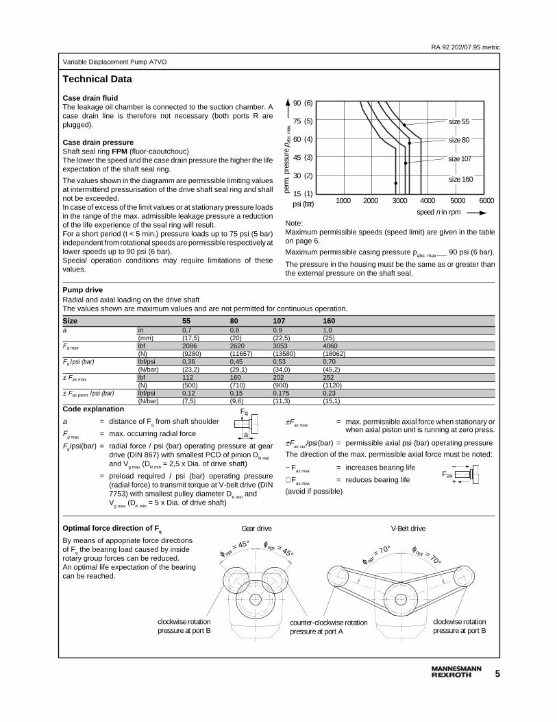
Case drain pressureShaft seal ring FPM (fluor-caoutchouc)The lower the speed and the case drain pressure the higher the lifeexpectation of the shaft seal ring.
The values shown in the diagramm are permissible limiting valuesat intermittend pressurisation of the drive shaft seal ring and shallnot be exceeded.In case of excess of the limit values or at stationary pressure loadsin the range of the max. admissible leakage pressure a reductionof the life experience of the seal ring will result.For a short period (t < 5 min.) pressure loads up to 75 psi (5 bar)independent from rotational speeds are permissible respectively atlower speeds up to 90 psi (6 bar).Special operation conditions may require limitations of thesevalues.
Code explanation
a = distance of Fq from shaft shoulder
Fq max = max. occurring radial force
Fq/psi(bar) = radial force / psi (bar) operating pressure at geardrive (DIN 867) with smallest PCD of pinion DR min
and Vg max (DR min = 2,5 x Dia. of drive shaft)
= preload required / psi (bar) operating pressure(radial force) to transmit torque at V-belt drive (DIN7753) with smallest pulley diameter D
K min and
Vg max
(DK min
= 5 x Dia. of drive shaft)
Optimal force direction of F q
By means of appopriate force directionsof Fq the bearing load caused by insiderotary group forces can be reduced.An optimal life expectation of the bearingcan be reached.
Note:Maximum permissible speeds (speed limit) are given in the tableon page 6.
Maximum permissible casing pressure pabs. max ____ 90 psi (6 bar).
The pressure in the housing must be the same as or greater thanthe external pressure on the shaft seal.
±Fax max = max. permissible axial force when stationary orwhen axial piston unit is running at zero press.
±Fax zul./psi(bar) = permissible axial psi (bar) operating pressure
The direction of the max. permissible axial force must be noted:
− Fax max = increases bearing life
+ Fax max
= reduces bearing life
(avoid if possible)
perm
. pre
ssur
e p a
bs. m
ax.
1000 2000 3000 4000 5000 6000
size 160
size 80
size 55
size 107
(6)
(5)
(4)
(3)
(2)
(1)(bar)
90
75
60
45
30
15psi
speed n in rpm
a
Fq
+
–Fax
ϕopt = 45°ϕ opt= 45°
Gear drive
ϕopt = 70°ϕ op
t= 70°
clockwise rotationpressure at port B
clockwise rotationpressure at port B
V-Belt drive
counter-clockwise rotationpressure at port A
RA 92 202/07.95 metric
6
Variable Displacement Pump A7VO
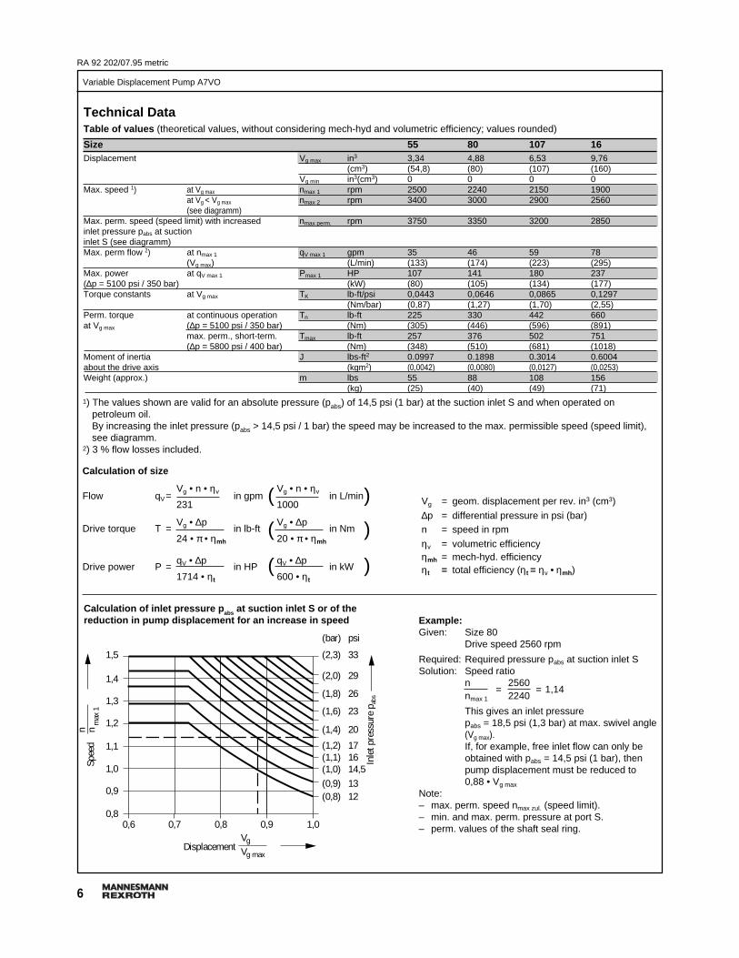
1) The values shown are valid for an absolute pressure (pabs) of 14,5 psi (1 bar) at the suction inlet S and when operated onpetroleum oil.By increasing the inlet pressure (pabs > 14,5 psi / 1 bar) the speed may be increased to the max. permissible speed (speed limit),see diagramm.
2) 3 % flow losses included.
Calculation of size
Vg • n • ηv Vg • n • ηvFlow qV= in gpm in L/min231 1000
Vg • ∆p Vg • ∆pDrive torque T = in lb-ft in Nm
24 • π • ηmh 20 • π • ηmh
qV • ∆p qV • ∆pDrive power P = in HP in kW
1714 • ηt 600 • ηt
( )
( )
( )
Vg = geom. displacement per rev. in3 (cm3)
∆p = differential pressure in psi (bar)n = speed in rpm
ηv = volumetric efficiencyηmh = mech-hyd. efficiencyηt = total efficiency (ηt = ηv • ηmh)
Calculation of inlet pressure p abs at suction inlet S or of thereduction in pump displacement for an increase in speed Example:
Given: Size 80Drive speed 2560 rpm
Required: Required pressure pabs at suction inlet SSolution: Speed ratio
n 2560= = 1,14
nmax 1 2240
This gives an inlet pressurepabs = 18,5 psi (1,3 bar) at max. swivel angle(Vg max).If, for example, free inlet flow can only beobtained with pabs = 14,5 psi (1 bar), thenpump displacement must be reduced to0,88 • Vg max
Note:– max. perm. speed nmax zul. (speed limit).– min. and max. perm. pressure at port S.– perm. values of the shaft seal ring.0,6 0,7 0,8 0,9 1,0
(2,3)
(2,0)
(1,8)
(1,6)
(1,4)
(1,2)(1,1)(1,0)(0,9)(0,8)
33
29
26
23
20
171614,51312
(bar) psi
1,5
1,4
1,3
1,2
1,1
1,0
0,9
0,8
n nm
ax 1
VgVg max
Displacement
Spee
d
Inle
t pre
ssur
e p a
bs
Technical DataTable of values (theoretical values, without considering mech-hyd and volumetric efficiency; values rounded)
Size 55 80 107 16Displacement Vg max in3 3,34 4,88 6,53 9,76
(cm3) (54,8) (80) (107) (160)Vg min in3(cm3) 0 0 0 0
Max. speed 1) at Vg max nmax 1 rpm 2500 2240 2150 1900at Vg < Vg max nmax 2 rpm 3400 3000 2900 2560(see diagramm)
Max. perm. speed (speed limit) with increased nmax perm. rpm 3750 3350 3200 2850inlet pressure pabs at suctioninlet S (see diagramm)Max. perm flow 2) at nmax 1 qV max 1 gpm 35 46 59 78
(Vg max) (L/min) (133) (174) (223) (295)Max. power at qV max 1 Pmax 1 HP 107 141 180 237(∆p = 5100 psi / 350 bar) (kW) (80) (105) (134) (177)Torque constants at Vg max TK lb-ft/psi 0,0443 0,0646 0,0865 0,1297
(Nm/bar) (0,87) (1,27) (1,70) (2,55)Perm. torque at continuous operation Tn lb-ft 225 330 442 660at Vg max (∆p = 5100 psi / 350 bar) (Nm) (305) (446) (596) (891)
max. perm., short-term. Tmax lb-ft 257 376 502 751(∆p = 5800 psi / 400 bar) (Nm) (348) (510) (681) (1018)
Moment of inertia J lbs-ft2 0.0997 0.1898 0.3014 0.6004about the drive axis (kgm2) (0,0042) (0,0080) (0,0127) (0,0253)Weight (approx.) m lbs 55 88 108 156
(kg) (25) (40) (49) (71)

7
Variable Displacement Pump A7VO
RA 92 202/07.95 metric
LR Constant Power Control
The constant power control controls the output volume of the pumpin relation to the operating pressure so that, at a constant drivespeed, the preset drive power is not exceeded.
pB • V
g = constant
pB
= operating pressureV
g= pump displacement
Optimum power usage is obtained by accurately following thepower hyberbola.Operating pressure applies a force on a piston within the controlpiston on to a rocker arm. An externally adjustable spring force isapplied to the other side of the rocker arm to determine the powersetting.Should the operating pressure exceed the set spring force, the pilotcontrol valve is operated via the rocker arm, allowing the pump toswivel towards zero output. This in turn reduces the effectivemoment on the arm of the rocker, thus allowing the operatingpressure to rise in the same ratio by which the output flow isreduced (p
B • V
g = constant).
In unoperated (zero pressure) condition, the pump is swivelled toits starting position (V
g max) by means of a control spring.
The start of control is adjustable from 725 psi to 3200 psi (50 barto 220 bar).
The output power (performance curve) is influenced by theefficiency of the pump.
When ordering, state in clear text:Input power P in HP or kWInput speed n in rpmMax. output flow qV max in gpm or L/minAfter all technical details have been clarified, a power diagrammcan be produced by computer.
Circuit diagrammConstant power control LR
R UA/B
X3
T1S
A1
Unit dimensions LR / LRGsee pages 17...20
A1 A/B R U
X3
A
P
TT1S
Variation: Remote pressure cut-off (G)
A sequence valve with subplate takes over the function of thepressure cut-off. The valve is mounted separate from the pump,and the simple piping length should not exceed 16 ft (5 m). Highpressure is supplied from the pump to the valve via port A1, and thevalve control oil is fed back to the pump via port X3, causing thepump to swivel back towards Vg min. Port T of the sequence valveand T1, the pilot drain from the pump must be connected back totank (cooler).Setting range from 725 psi to 4600 psi (50 bar to 315 bar)
Any pressure relief valve included in the circuit to limit the max.pressure must be set to a cracking pressure at least 290 psi (20 bar)above the pressure control setting.
The sequence valve and subplate must be ordered separately.
Sequence valve: DZ5DP2-1X/315 YMSO21 (Id.-Nr. 154 869)Subplate: G 115/1 (Id.-Nr. 153 138)
When ordering, state in clear text:Setting of the pressure cut-off
Circuit diagrammConstant power control with remote pressure cut-off, LRG
Oper
atin
g pr
essu
re p
B
Setti
ng ra
nge
DisplacementVg min Vg max
min
max
(315 bar)4600 psi
(50 bar)725 psi
0 0,2 0,4 0,6 0,8 1,0
(350)
(300)
(250)
(200)
(150)
(100)
(50)
0
5100
4350
3600
2900
2200
1450
725
(220 bar)3200 psi
(50 bar)725 psi
Vg min Vg max
psi (bar)
Oper
atin
g pr
essu
re p
B
Setting rangeStart of control
Displacement
RA 92 202/07.95 metric
8
Variable Displacement Pump A7VO
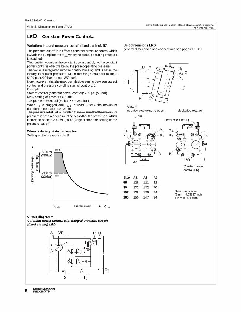
LRD Constant Power Control...
Variation: Integral pressure cut-off (fixed setting), (D)
The pressure cut-off is in effect a constant pressure control whichswivels the pump back to V
g min when the preset operating pressure
is reached.This function overrides the constant power control, i.e. the constantpower control is effective below the preset operating pressure.The valve is integrated into the control housing and is set in thefactory to a fixed pressure, within the range 2900 psi to max.5100 psi (200 bar to max. 350 bar).Note, however, that the max. permissible setting between start ofcontrol and pressure cut-off is start of control x 5.Example:Start of control (constant power control): 725 psi (50 bar)Max. setting of pressure cut-off:725 psi • 5 = 3625 psi (50 bar • 5 = 250 bar)When T1 is plugged and Ttank ≤ 120°F (50°C) the maximumduration of operation is ≤ 2 min.The pressure relief valve installed to make sure that the maximumpressure is not exceeded must be set so that the pressure at whichit starts to open is 290 psi (20 bar) higher than the setting of thepressure cut-off.
When ordering, state in clear text:Setting of the pressure cut-off
A1 A/B R U
X3
T1S
Prior to finalising your design, please obtain a certified drawing.All rights reserved.
AX
1
3
T1
A1
R
RU
AX
1
3
A3
A2
A
S
AX
1
3
B
T1
S
Y
T1
View Ycounter-clockwise rotation clockwise rotation
Size A1 A2 A3
55 128 121 62
80 132 132 70
107 138 136 74
160 150 147 84
Unit dimensions LRDgeneral dimensions and connections see pages 17...20
Pressure cut-off (D)
Constant powercontrol (LR)
Dimensions in mm(1mm = 0,03937 inch1 inch = 25,4 mm)
Circuit diagrammConstant power control with integral pressure cut-off(fixed setting) LRD
Vg min Vg max
5100 psi(350 bar)
2900 psi(200 bar) min
max
Displacement
Setti
ng ra
nge
Oper
atin
g pr
essu
re p
B

9
Variable Displacement Pump A7VO
RA 92 202/07.95 metric
800
700
600
500
400
300
200
100
0 0,2 0,4 0,6 0,8 1,0Vg min Vg max
Prior to finalising your design, please obtain a certified drawing.All rights reserved.
LR.U Constant Power Control ...
Variation: Electrical stroke limiter (U)
The electrical stroke limiter allows the maximum displacement tobe infinitely varied or limited as required.The displacement is set by means of the pilot current generated bythe proportional solenoid.A 24V DC supply and a current of between 200 and 600 mA arerequired for the control of the proportional solenoid.The electrical stroke limiter is overriden by the constant power control,i.e. below the power curve (power hyperbola), displacement isadjusted in relation to the pilot current. If the set flow or the operatingpressure is such that the power curve is exceeded, the constant powercontrol overrides the stroke limiter and reduces displacement until thepower hyperbola is restored.
As the pilot current increases, the pump swivels to a lowerdisplacement.In unoperated (zero pressure) condition, the pump is swivelled toits starting position (Vg max) by means of a control spring.
Start of control (at Vg max
) ______________________ 200 mA
End of control (at Vg min
) ______________________ 600 mA
Control from Vg max
to Vg min
Unit dimensions LRDUgeneral dimensions and connections see pages 17...20
View Ycounter-clockwise rotation clockwise rotation
Pressurecut-off (D)
Constant powercontrol (LR)
Pilo
t cur
rent
in m
A
Circuit diagramm:Constant power control with pressure cut-off andelectrical stroke limiter , LRDU
A1 A/B R U
X3
Y3
T1S
AX
1
3
T1
A4
R
RU
AX
1
3
A
S
T1 AX
1
3
B
T1
S
Y
Y3Y3
A5
A2 (Y3)
A3
A1
Y3
PortY3 remote control pressure M14x1,5 (plugged)
Size A1 A2 A3 A4 A5
55 276 251 245 105 12
80 304 279 257 116 14
107 321 295 264 122 18
160 360 334 282 140 19
Dimensions in mm(1mm = 0,03937 inch1 inch = 25,4 mm)
Displacement

RA 92 202/07.95 metric
10
Variable Displacement Pump A7VO
(40)
(35)
(30)
(25)
(20)
(15)
(10)
(4)
580
510
435
365
290
220
145
60
0 0,2 0,4 0,6 0,8 1,0Vg min Vg max
(bar)psi
0 0,2 0,4 0,6 0,8 1,0Vg min Vg max
580
510
435
365
290
220
145
60
(bar)psi
(40)
(35)
(30)
(25)
(20)
(15)
(10)
(4)
psi
PortsY3 remote control pressure M14x1,5 (plugged)X1 pilot pressure M14x1,5
Size A1 A2 A3 A4 A5 A6 A7
55 262 257 252 170 127 105 12
80 290 284 279 182 138 116 14
107 309 300 295 189 144 122 18
160 351 340 334 207 162 140 19
Prior to finalising your design, please obtain a certified drawing.All rights reserved.
LR.H. Constant Power Control...
Variation: Hydraulic stroke limiter (H...)
The hydraulic stroke limiter allows the maximum displacement tobe infinitely varied or limited as required.Control range Vg max to Vg min .The displacement is set by means of the pilot pressure applied atport X1.The hydraulic stroke limiter is overriden by the constant powercontrol, i.e. below the power curve (power hyperbola), displacementis adjusted in relation to pilot pressure. If the set flow or the operatingpressure is such that the power curve is exceeded, the constantpower control overrides the stroke limiter and reduces displacementuntil the power hyperbola is restored.
H1/H5 ➝ Function: V g max to Vg min (negative control )As pilot pressure increases the pump swivels towards lowerdisplacement.In unoperated (zero pressure) condition, the pump is swivelled toits starting position (Vg max) by means of a control spring.
Start of control, (at Vg max
), adjustable from 60 psi to 220 psi ( 4 barto 15 bar).
When ordering, please state required start of control in clear text.
H1 ➔ pilot pressure increase (Vg max – Vg min) __ ∆p = 365 psi (25 bar)
A pressure of 580 psi (40 bar) is necessary to operate the control.The required control oil is taken from the high pressure circuit.If necessary, a boost pressure of ≥ 580 psi (40 bar) should beapplied at port Y3.If the H-function is used for two-point switching control only (Vg max
- Vg min), pilot pressure at port X1 must not exceed 580 psi (40 bar).
AX
1
3
T1
A6
R
RU
AX
1
3
A
S
T1 AX
1
3
B
T1
S
Y
X1
Y3
X1
Y3
A7
A3 (Y3)
A5 A
4
A2 (X1)A1
X1
Y3
Circuit diagramm:Constant power control with pressure cut-off and hydraulicstroke limiter (negative control), LRDH1, LRDH5
Unit dimensions LRDH1, LRDH5general dimensions and connections see pages 17...20
View Ycounter-clockwise rotation clockwise rotation
Pressure cut-off (D)
Constant power control(LR)
A1
Y3
X3
T1S
A/B X1 R U
Dimensions in mm(1mm = 0,03937 inch1 inch = 25,4 mm)
Displacement
Setti
ng ra
nge
H5 ➔ pilot pressure increase (Vg max – Vg min) __ ∆p = 145 psi (10 bar)
Displacement
Setti
ng ra
nge
Pilo
t pre
ssur
e p S
tPi
lot p
ress
ure
p St

11
Variable Displacement Pump A7VO
RA 92 202/07.95 metric
0 0,2 0,4 0,6 0,8 1,0Vg min Vg max
(40)
(35)
(30)
(25)
(20)
(15)
(10)
(4)
580
510
435
365
290
220
145
60
(bar)psi
0 0,2 0,4 0,6 0,8 1,0Vg min Vg max
(40)
(35)
(30)
(25)
(20)
(15)
(10)
(4)
580
510
435
365
290
220
145
60
(bar)psi
Size A1 A2 A3 A4 A5 A6 A7
55 261 256 251 211 127 105 12
80 289 284 281 225 141 120 14
107 308 299 295 232 145 125 18
160 352 341 334 250 163 144 19
Dimensions in mm(1mm = 0,03937 inch1 inch = 25,4 mm)
Prior to finalising your design, please obtain a certified drawing.All rights reserved.
AX
1
3
T1
A6
R
RU
AX
1
3
A
S
1 AX
1
3
B
T1
S
Y
X1
Y3
X1
Y3
A7
A3 (Y3)
A5
A4
A2 (X1)A1
X1
Y3
T
View Ycounter-clockwise rotation clockwise rotation
Pressure cut-off (D)
Unit dimensions LRDH2, LRDH6general dimensions and connections see pages 17...20
S
A/BA1 X1 R U
X3
Y3
T1
A pressure of 580 psi (40 bar) is necessary to operate the control.The required control oil is taken from the high pressure circuit.If necessary, a boost pressure of ≥ 580 psi (40 bar) should beapplied at port Y3.If the H-function is used for two-point switching control only (Vg min
- Vg max), pilot pressure at port X1 must not exceed 580 psi (40 bar).
H2/H6 ➝ Function: V g min to Vg max (positive control)As pilot pressure increases the pump swivels towards higherdisplacement.In unoperated (zero pressure) condition, the pump is swivelled toits starting position (Vg max) by means of a control spring.
If the operating pressures is ≥ 580 psi (40 bar), the pump swivelsfrom Vg max to Vg min (pilot pressure ≤ start of control).
Start of control, (at Vg min
), adjustable from 60 psi to 220 psi ( 4 barto 15 bar)
When ordering, please state required start of control in clear text.
H2 ➔ pilot pressure increase (Vg min
– Vg max
) __ ∆p = 365 psi (25 bar)
Circuit diagramm:Constant power control with pressure cut-off and hydraulicstroke limiter (positive control), LRDH2, LRDH6
Setti
ng ra
nge
Displacement
Displacement
Setti
ng ra
nge
H6 ➔ pilot pressure increase (Vg min
– Vg max
) __ ∆p = 145 psi (10 bar)
Pilo
t pre
ssur
e p S
tPi
lot p
ress
ure
p St
RA 92 202/07.95 metric
12
Variable Displacement Pump A7VO
Vg min Vg max
5100 psi(350 bar)
725 psi(50 bar)
max
. 145
psi
min
max
(10
bar)
Prior to finalising your design, please obtain a certified drawing.All rights reserved.
Circuit diagramm:Constant pressure control DR (integral valve), fixed setting
A1
X3
T1S
A/B R U
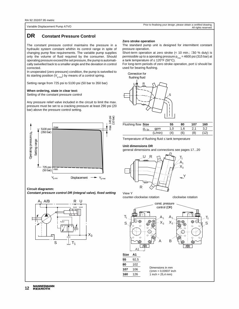
DR Constant Pressure Control
The constant pressure control maintains the pressure in ahydraulic system constant whithin its control range in spite ofchanging pump flow requirements. The variable pump suppliesonly the volume of fluid required by the consumer. Shouldoperating pressure exceed the set pressure, the pump is automati-cally swivelled back to a smaller angle and the deviation in controlcorrected.In unoperated (zero pressure) condition, the pump is swivelled toits starting position (V
g max) by means of a control spring.
Setting range from 725 psi to 5100 psi (50 bar to 350 bar)
When ordering, state in clear text:Setting of the constant pressure control
Any pressure relief valve included in the circuit to limit the max.pressure must be set to a cracking pressure at least 290 psi (20bar) above the pressure control setting.
Dimensions in mm(1mm = 0,03937 inch1 inch = 25,4 mm)
Size A1
55 92,5
80 102
107 106
160 126
Zero stroke operationThe standard pump unit is designed for intermittent constantpressure operation.Short-term operation at zero stroke (< 10 min.; ∼50 % duty) ispermissible up to a operating pressure pmax = 4600 psi (315 bar) ata tank temperature of ≤ 120°F (50°C).For long-term periods of zero stroke operation, port U should beused for bearing flushing.
U R
S
Connection forflushing fluid
View Ycounter-clockwise rotation clockwise rotation
const. pressurecontrol (DR)
Flushing flow Size 55 80 107 160qV Sp gpm 1,0 1,6 2,1 3,2
(L/min) (4) (6) (8) (12)
Temperature of flushing fluid ≤ tank temperature
Unit dimensions DRgeneral dimensions and connections see pages 17...20
AX
1
3
T1
R
RU
AX
1
3
A1
A
S
T1 AX
1
3
B
T1
S
Y
Oper
atin
g pr
essu
re p
B
Setti
ng ra
nge
Displacement

13
Variable Displacement Pump A7VO
RA 92 202/07.95 metric
Vg min Vg max
4600 psi(315 bar)
725 psi(50 bar)
max
. 145
psi
(10
bar)
min
max
Prior to finalising your design, please obtain a certified drawing.All rights reserved.
Variation: Remote constant pressure control (G)A sequence valve with subplate takes over the pressure controlfunction. The valve is mounted separate from the pump, and thesimple piping length should not exceed 16 ft (5 m). High pressureis supplied from the pump to the valve via port A1, and the valvecontrol oil is fed back to the pump via port X3, causing the pumpto swivel back towards Vg min. Port T of the sequence valve andT1, the pilot drain from the pump must be connected back to tank(cooler).
Setting range from 725 psi to 4600 psi (50 bar to 315 bar).
Any pressure relief valve included in the circuit to limit the max.pressure must be set to a cracking pressure at least 290 psi (20bar) above the pressure control setting.
The sequence valve and subplate must be ordered separately.
Sequence valve: DZ5DP2-1X/315YMSO21 (Id.-Nr. 154 869)Subplate: G 115/1 (Id.-Nr. 153 138)
When ordering, state in clear text:Setting of the constant pressure control
X3
T1S
A/B R U
P
A
T
A1
Circuit diagramm:Remote constant pressure control DRG
Unit dimensions DRGsee control device DR,general dimensions and connections see pages 17...20
Ports A1 and X3 are open
Displacement
Setti
ng ra
nge
Oper
atin
g pr
essu
re p
B
RA 92 202/07.95 metric
14
Variable Displacement Pump A7VO
0 0,2 0,4 0,6 0,8 1,0Vg min Vg max
(40)
(35)
(30)
(25)
(20)
(15)
(10)
(4)
580
510
435
365
290
220
145
60
(bar)psi
0 0,2 0,4 0,6 0,8 1,0Vg min Vg max
(40)
(35)
(30)
(25)
(20)
(15)
(10)
(4)
580
510
435
365
290
220
145
60
(bar)psi
Prior to finalising your design, please obtain a certified drawing.All rights reserved.
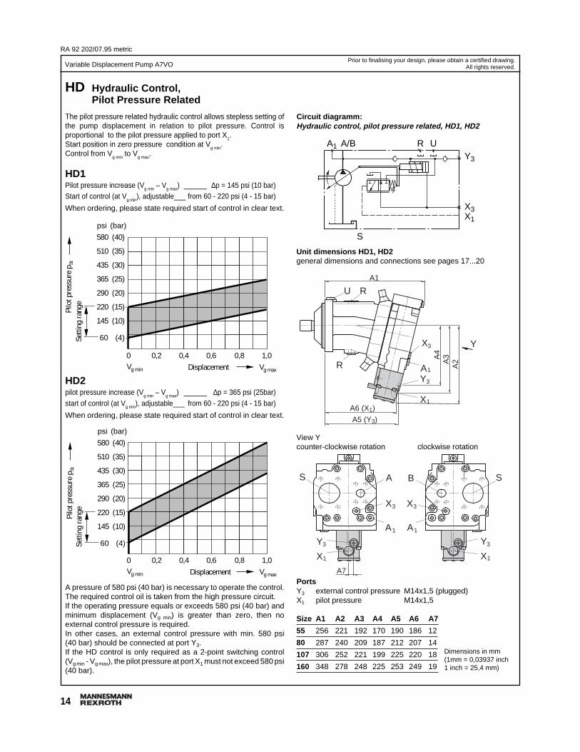
HD Hydraulic Control,Pilot Pressure Related
The pilot pressure related hydraulic control allows stepless setting ofthe pump displacement in relation to pilot pressure. Control isproportional to the pilot pressure applied to port X
1.
Start position in zero pressure condition at Vg min
.Control from V
g min to V
g max.
HD1Pilot pressure increase (Vg min – Vg max) ______ ∆p = 145 psi (10 bar)Start of control (at V
g min), adjustable___ from 60 - 220 psi (4 - 15 bar)
When ordering, please state required start of control in clear text.
Circuit diagramm:Hydraulic control, pilot pressure related, HD1, HD2
A pressure of 580 psi (40 bar) is necessary to operate the control.The required control oil is taken from the high pressure circuit.If the operating pressure equals or exceeds 580 psi (40 bar) andminimum displacement (Vg min) is greater than zero, then noexternal control pressure is required.In other cases, an external control pressure with min. 580 psi(40 bar) should be connected at port Y3.If the HD control is only required as a 2-point switching control(Vg min - Vg max), the pilot pressure at port X1 must not exceed 580 psi(40 bar).
HD2pilot pressure increase (Vg min – Vg max) ______ ∆p = 365 psi (25bar)start of control (at Vg min), adjustable___ from 60 - 220 psi (4 - 15 bar)
When ordering, please state required start of control in clear text.
PortsY3 external control pressure M14x1,5 (plugged)X1 pilot pressure M14x1,5
Size A1 A2 A3 A4 A5 A6 A7
55 256 221 192 170 190 186 12
80 287 240 209 187 212 207 14
107 306 252 221 199 225 220 18
160 348 278 248 225 253 249 19
Dimensions in mm(1mm = 0,03937 inch1 inch = 25,4 mm)
A1
Y3
X3X1
A/B R U
S
View Ycounter-clockwise rotation clockwise rotation
A
X
1
3
R
RU
A
X
1
3
AS
A
X
1
3
B S
Y
X1
Y3
A1
A7
A5 (Y3)
A6 (X1)
A2
X1
Y3
X1
Y3
A4
A3
Unit dimensions HD1, HD2general dimensions and connections see pages 17...20
Displacement
Setti
ng ra
nge
Displacement
Setti
ng ra
nge
Pilo
t pre
ssur
e p S
tPi
lot p
ress
ure
p St

15
Variable Displacement Pump A7VO
RA 92 202/07.95 metric
Vg min Vg max
4600 psi(315 bar)
725 psi(50 bar)
max
. 145
psi
(10
bar)
min
max
Prior to finalising your design, please obtain a certified drawing.All rights reserved.
Variation: Remote pressure cut-off (G)
A sequence valve with subplate takes over the function of thepressure cut-off. The valve is mounted separate from the pump,and the simple piping length should not exceed 16 ft (5 m). Highpressure is supplied from the pump to the valve via port A1.The control oil of the pump is directed to the valve via the port X3
and led into the tank at port A located on the subplate of thesequence valve. In this case the pump is regulated to Vg min in caseof access of the set-point pressure value.Note: Port A of the sequence valve must be connected back to tank(cooler).
Setting range from 725 psi to 4600 psi (50 bar to 315 bar).
Any pressure relief valve included in the circuit to limit the max.pressure must be set to a cracking pressure at least 290 psi (20 bar)above the pressure control setting.
The sequence valve and subplate must be ordered separately.
Sequence valve: DZ5DP2-1X/315XSO20 (Id.-Nr. 154 768)Subplate: G 115/1 (Id.-Nr. 153 138)
When ordering, state in clear text:Setting of the pressure cut-off
Unit dimensions HD1G/HD2Gsee control device HD1/HD2,general dimensions and connections see pages 17...20
Ports A1 and X3 are open
A1
Y3
X3
X1
S
A
X
P
A/B R U
Circuit diagramm:Hydraulic control, pilot pressure related with remotepressure cut-off , HD1G, HD2G
Displacement
Setti
ng ra
nge
Oper
atin
g pr
essu
re p
B

RA 92 202/07.95 metric
16
Variable Displacement Pump A7VO
800
700
600
500
400
300
200
100
0 0,2 0,4 0,6 0,8 1,0Vg min Vg max
Prior to finalising your design, please obtain a certified drawing.All rights reserved.
Pilo
t cur
rent
in m
A
Displacement
Suitable control for the proportional solenoid are proportionalamplifier PV (catalogue sheet RA 95 023) and chopper amplifierCV (catalogue sheet RA 95 029).By using an electronic control card control of swivel time is alsopossible.Note: Pumps with EP control may only be mounted within an oiltank when using petroleum hydraulic oils and with oil temperaturesin the tank of max. 175°F (80°C).
Circuit diagramm:Electrical control with proportional solenoid, EP
Y3
X3
A/B UR
S
A1
EP Electrical Controlwith Porportional Solenoid
The electrical control with proportional solenoid allows steplessand programmable setting of the pump displacement. Control isproportional to solenoid force (current strength). The control forceat the control piston is generated by a proportional solenoid.For control of the proportional solenoid, a 24 V DC supply withcurrent levels between 200 and 600 mA is required.
Start of control (at Vg min) ______________________ 200 mA
End of control (at Vg max) _____________________ 600 mA
Insulation class IP 54
Start position in zero pressure condition at Vg min.
Control from Vg min to Vg max
A pressure of 580 psi (40 bar) is necessary to operate the control.The required control oil is taken from the high pressure circuit.If the operating pressure equals or exceeds 580 psi (40 bar) andminimum displacement (Vg min) is greater than zero, then noexternal control pressure is required.In other cases, an external control pressure with min. 580 psi(40 bar) should be connected at port Y3.
Unit dimensions EPgeneral dimensions and connections see pages 17...20
A
X
1
3
R
RU
A
X
1
3
AS
A
X
1
3
B S
Y
Y3
A1
A5
A4 (Y3)
Y3
Y3
A3
A2
View Ycounter-clockwise rotation clockwise rotation
PortY3 external control pressure M14x1,5 (plugged)Size A1 A2 A3 A4 A5
55 256 296 170 190 12
80 287 315 187 212 14
107 306 327 199 225 18
160 348 353 225 253 19
Variation: Remote pressure cut-off (G)Description see HD1G/HD2G, page 15Circuit diagramm EPG
A1
Y3
X3
A/B R U
S
P
X
A
Dimensions in mm(1mm = 0,03937 inch1 inch = 25,4 mm)
17
Variable Displacement Pump A7VO
RA 92 202/07.95 metric
262232
7520
32 U R12
°30´
7.5
62
31
ø70
ø12
5-0
.025
140
TAX
1
1
3
35
142 Y
241 (A1; T1)
242 (X3)
R
50.8
AX
1
3
49 77.8
57
12
3249
A
AX
1
3
B
S
T1
76 90
ø19
23.8 42.9
4932
100
150
150
ø13
.5
ø160
45°45°
S
T1
12
35
Prior to finalising your design, please obtain a certified drawing.All rights reserved.
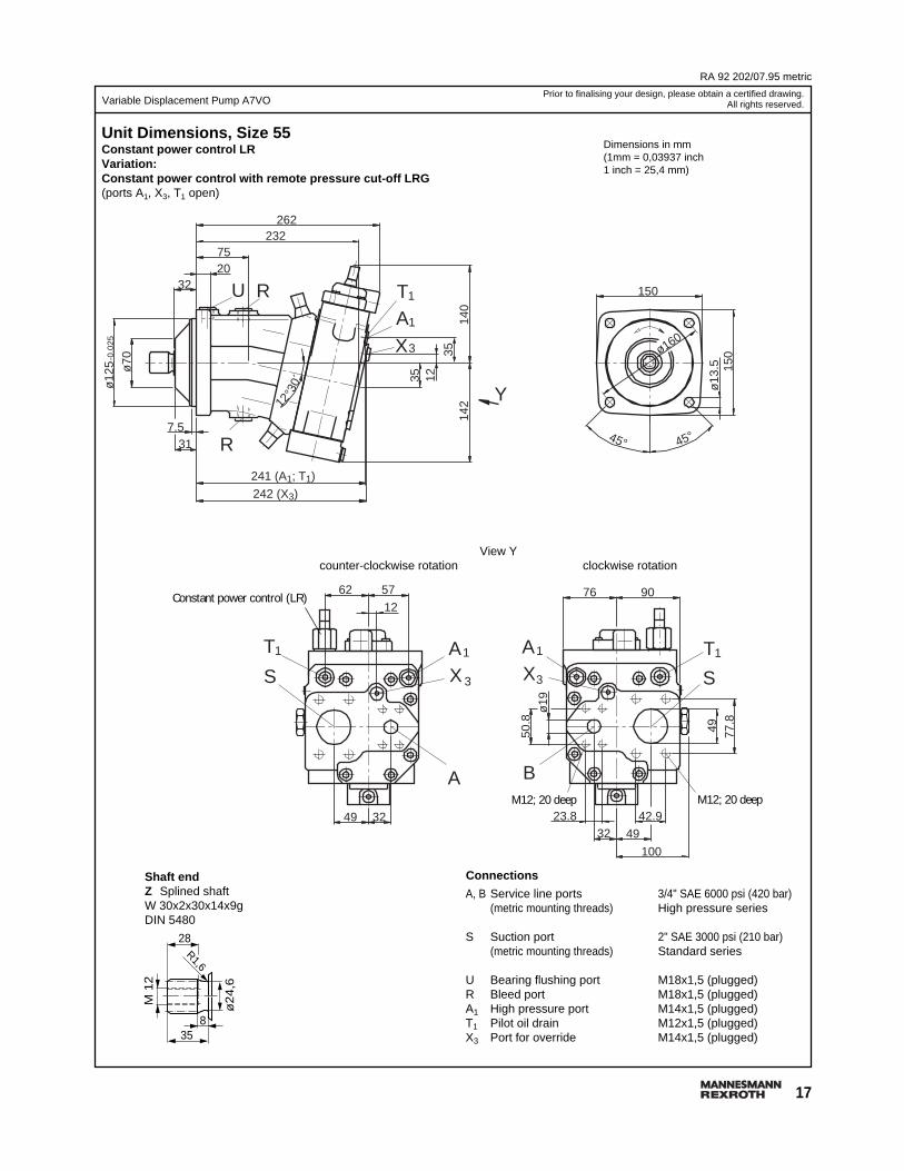
Unit Dimensions, Size 55Constant power control LRVariation:Constant power control with remote pressure cut-off LRG(ports A1, X3, T1 open)
View Ycounter-clockwise rotation clockwise rotation
M12; 20 deepM12; 20 deep
Constant power control (LR)
Shaft endZ Splined shaftW 30x2x30x14x9gDIN 5480
835
ø2
4,6
M 1
2
28R1,6
Connections
A, B Service line ports 3/4" SAE 6000 psi (420 bar)(metric mounting threads) High pressure series
S Suction port 2" SAE 3000 psi (210 bar)(metric mounting threads) Standard series
U Bearing flushing port M18x1,5 (plugged)R Bleed port M18x1,5 (plugged)A1 High pressure port M14x1,5 (plugged)T1 Pilot oil drain M12x1,5 (plugged)X3 Port for override M14x1,5 (plugged)
Dimensions in mm(1mm = 0,03937 inch1 inch = 25,4 mm)

RA 92 202/07.95 metric
18
Variable Displacement Pump A7VO
Unit Dimensions, Size 80Constant power control LRVariation:Constant power control with remote pressure cut-off LRG(ports A1, X3, T1 open)
57.2
AX
1
3
165
AX
1
3
T1
144
37
157
Y
265 (X3)270 (A1; T1)
R
12° 30
´
317.5
ø83
ø14
0-0
.025
32 RU23
84
287253
ø13
.5
165
ø180
45°45°
64 6222
57 34
A
S
T1 AX
1
3
B
T1
S
ø25
80 102
88.9
62
1115734
27.8 50.8
17
40
Constant power control (LR)
Dimensions in mm(1mm = 0,03937 inch1 inch = 25,4 mm)
Prior to finalising your design, please obtain a certified drawing.All rights reserved.
View Ycounter-clockwise rotation clockwise rotation
M12; 17 deep
Connections
A, B Service line ports 1" SAE 6000 psi (420 bar)(metric mounting threads) High pressure series
S Suction port 2 1/2" SAE 2500 psi (170 bar)(metric mounting threads) Standard series
U Bearing flushing port M18x1,5 (plugged)R Bleed port M18x1,5 (plugged)A1 High pressure port M16x1,5 (plugged)T1 Pilot oil drain M12x1,5 (plugged)X3 Port for override M16x1,5 (plugged)
Shaft endZ Splined shaftW 35x2x30x16x9gDIN 5480
28
ø29
,6
R 1,6
840
M 1
2
M12; 17 deep

19
Variable Displacement Pump A7VO
RA 92 202/07.95 metric
Prior to finalising your design, please obtain a certified drawing.All rights reserved.
Unit Dimensions, Size 107Constant power control LRVariation:Constant power control with remote pressure cut-off LRG(ports A1, X3, T1 open)
Shaft endZ Splined shaftW 40x2x30x18x9gDIN 5480
Connections
A, B Service line ports 1" SAE 6000 psi (420 bar)(metric mounting threads) High pressure series
S Suction port 2 1/2" SAE 2500 psi (170 bar)(metric mounting threads) Standard series
U Bearing flushing port M18x1,5 (plugged)R Bleed port M18x1,5 (plugged)A1 High pressure port M16x1,5 (plugged)T1 Pilot oil drain M12x1,5 (plugged)X3 Port for override M16x1,5 (plugged)
Dimensions in mm(1mm = 0,03937 inch1 inch = 25,4 mm)
View Ycounter-clockwise rotation clockwise rotation
AX
1
3
T1
-0.0
25
ø17
.5
ø16
0
SAX
1
3
T
88
ø25 62 88.9
B
AX
1
3
T1
150
190
115
50.8
553627.8
1
105
57.2
A
S
72 7022
55 36
190
307
284 (X3)
ø90
40 2586
272
39
7.5
289 (A1)
30´ 41
12°
170 Y
R
RU
45° 45°
ø20018
37
286 (T1)
46
M12; 17 deep
845
ø34
,6
M 1
2
28R2,5
Constant power control (LR)
M12; 17 deep

RA 92 202/07.95 metric
20
Variable Displacement Pump A7VO
Y
210
ø224
45° 45°
ø17
.5
AX
1
3
T1
160
47
193
210
ø10
0-0.0
25
30´
12°
R
327 (X3)331 (A1)
39
7.5
RU
ø18
0
40 28101
310
349
AX
1
3
T1
ø32 7566.7
A
S
84
B
AX
1
3
7822
4066 31.8
T1
S
106.
4
6661.9
100
40
126
46 55
27
328 (T1)
Prior to finalising your design, please obtain a certified drawing.All rights reserved.
Unit Dimensions, Size 160Constant power control LRVariation:Constant power control with remote pressure cut-off LRG(ports A1, X3, T1 open)
Dimensions in mm(1mm = 0,03937 inch1 inch = 25,4 mm)
Shaft endZ Splined shaftW 45x2x30x21x9gDIN 5480
850
ø39
,6
M 1
6
36R2,5
Connections
A, B Service line ports 1 1/4" SAE 6000 psi (420 bar)(metric mounting threads) High pressure series
S Suction port 3" SAE 2000 psi (140 bar)(metric mounting threads) Standard series
U Bearing flushing port M18x1,5 (plugged)R Bleed port M18x1,5 (plugged)A1 High pressure port M16x1,5 (plugged)T1 Pilot oil drain M12x1,5 (plugged)X3 Port for override M16x1,5 (plugged)
M16; 24 deepM14; 19 deep
Constant power control (LR)
View Ycounter-clockwise rotation clockwise rotation
Mannesmann Rexroth Corporation Rexroth Hydraulics Div., Industrial, 2315 City Line Road, Bethlehem, PA 18017-2131 Tel. (610) 694-8300 Fax: (610) 694-8467Rexroth Hydraulics Div., Mobile, 1700 Old Mansfield Road, Wooster, OH 44691-0394 Tel. (330) 263-3400 Fax: (330) 263-3333
All rights reserved – Subject to revisionPrinted in U.S.A.