variable angle lcp two-column volar distal radius plate 2 ...synthes.vo.llnwd.net/o16/llnwmb8/int...
TRANSCRIPT

Variable Angle LCP Two-Column Volar Distal Radius Plate 2.4. For fragment-specific fracture fixation with variable angle locking technology.
Surgical Technique
This publication is not intended for distribution in the USA.
Instruments and implants approved by the AO Foundation.

Image intensifier control
WarningThis description alone does not provide sufficient background for direct use of DePuy Synthes products. Instruction by a surgeon experienced in handling these products is highly recommended.
Processing, Reprocessing, Care and MaintenanceFor general guidelines, function control and dismantling of multi-part instruments, as well as processing guidelines for implants, please contact your local sales representative or refer to:http://emea.depuysynthes.com/hcp/reprocessing-care-maintenanceFor general information about reprocessing, care and maintenance of Synthes reusable devices, instrument trays and cases, as well as processing of Synthes non-sterile implants, please consult the Important Information leaflet (SE_023827) or refer to: http://emea.depuysynthes.com/hcp/reprocessing-care-maintenance

Variable Angle LCP Two-Column Volar Distal Radius Plate 2.4 Surgical Technique DePuy Synthes 1
Table of Contents
Introduction
Surgical Technique
Product Information
Bibliography 38
MRI Information 40
VA-LCP Two-Column Distal Radius Plate 2.4 2
AO Principles 4
Indications 5
Clinical Cases 6
Three Column Theory 7
Screw Insertion Techniques 8
Screw Angle Overview 10
Approach 12
Implantation 13
Postoperative Treatment/Implant Removal 28
Tips 29
Plates 30
Screws 31
Optional: Trial Implants 33
Instruments 34

2 DePuy Synthes Variable Angle LCP Two-Column Volar Distal Radius Plate 2.4 Surgical Technique
Variable Angle LCP Two-Column Volar Distal Radius Plate 2.4. For fragment-specific fracture fixation with variable angle locking technology.
Features and Benefits
Oblong combi-holeAllows accurate plate positioning on the bone
Dedicated screwsFor fi xation of radial styloid (blue) and support of lunate facet and DRUJ (green)
BendableTwo columns allow independent fi ne contouring of the radial and intermedi-ate columns
The Variable Angle LCP Two-Column Volar Distal Radius Plate 2.4, featuring variable angle locking technology, is indi-cated for intra- and extra-articular fractures and osteotomies of the distal radius. All implants are available in stainless steel and titanium.

Variable Angle LCP Two-Column Volar Distal Radius Plate 2.4 Surgical Technique DePuy Synthes 3
Kirschner wire holesEnable preliminary plate fi xation
Guiding blockAllows guided drilling and screw inser-tion in the predefi ned nominal angle
Anatomical fitClose to the volar ridge with rounded plate edges, polished surface and countersunk screws to reduce the risk of soft tissue irritation
Variable angle lockingHoles allow up to 15° off-axis screw angulation in all directions in order to address the individual fracture patterns

4 DePuy Synthes Variable Angle LCP Two-Column Volar Distal Radius Plate 2.4 Surgical Technique
AO Principles
In 1958, the AO formulated four basic principles, which have become the guidelines for internal fixation.1, 2 The principles as applied to the Variable Angle LCP Two-Column Volar Distal Radius Plates 2.4 are:
Anatomic reductionThe use of variable angle locking technology allows frag-ment-specific fixation by providing the flexibility to lock screws in trajectories that can diverge from the central axis of the plate hole. Variable screw angles provide fixation op-tions for a variety of fracture patterns.
Stable fixationVariable angle locking screws create a locked construct, providing angular stability.
Preservation of blood supplyLimited-contact plate design reduces plate-to-bone contact, limiting vascular trauma. Additionally, locked plates do not require close contact with the bone.
Early, active mobilizationEarly mobilization per standard AO technique creates an environment for bone healing, expediting a return to optimal function.
1 Müller ME, Allgöwer M, Schneider R, Willenegger H (1995) Manual of Internal Fixation. 3rd, expanded and completely revised ed. 1991. Berlin, Heidelberg, New York: Springer
2 Rüedi TP, Buckley RE, Moran CG (2007) AO Principles of Fracture Management. 2nd expanded ed. 2002. Stuttgart, New York: Thieme

Variable Angle LCP Two-Column Volar Distal Radius Plate 2.4 Surgical Technique DePuy Synthes 5
Indications
Variable Angle LCP Two-Column Volar Distal Radius Plates 2.4 are indicated for the fixation of intra- and extra-articular fractures and osteotomies of the distal radius.

6 DePuy Synthes Variable Angle LCP Two-Column Volar Distal Radius Plate 2.4 Surgical Technique
Postoperative, AP view Postoperative, lateral view, 20° inclined
Postoperative, AP view Postoperative, lateral view
Clinical Cases
Case 124-year-old male with AO 23C2.1 fracture, fall from scaffold
Preoperative, AP view Preoperative, lateral view
Preoperative, AP view Preoperative, lateral view
Case 277-year-old female with AO 23C1 fracture, fall
Variable Angle LCP Two-Column Volar Distal Radius Plate 2.4 Surgical Technique DePuy Synthes 7
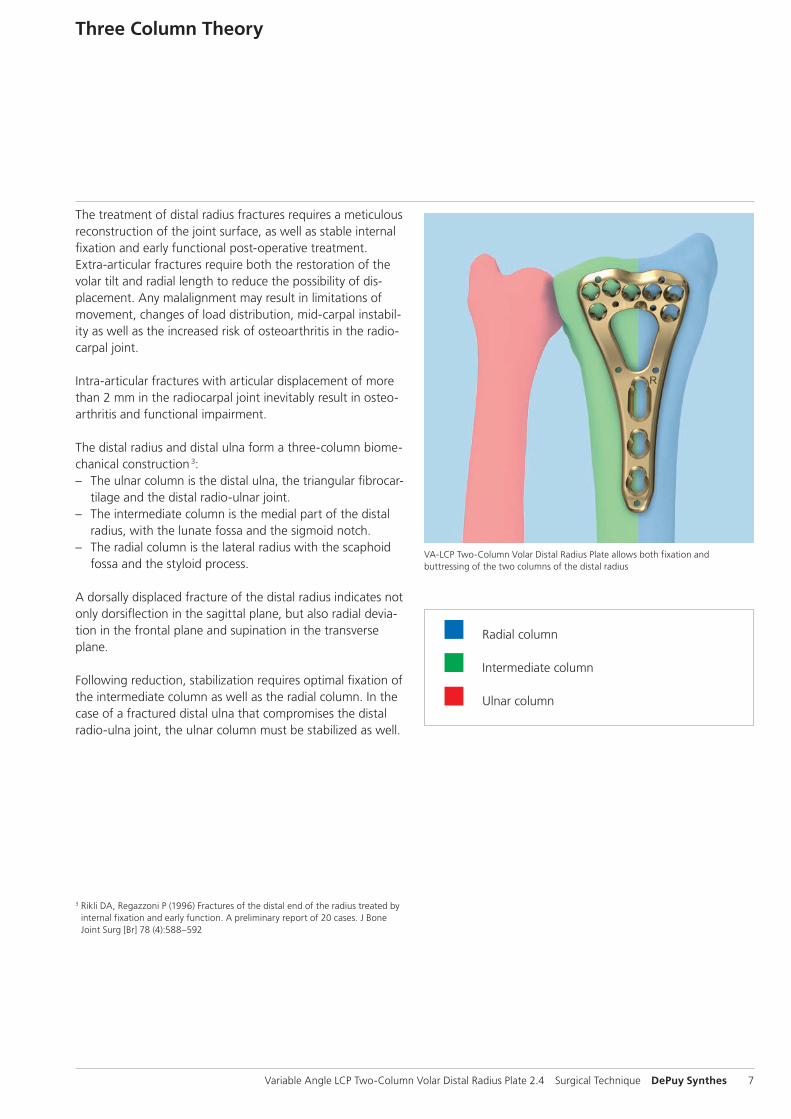
Three Column Theory
3 Rikli DA, Regazzoni P (1996) Fractures of the distal end of the radius treated by internal fixation and early function. A preliminary report of 20 cases. J Bone Joint Surg [Br] 78 (4):588–592
VA-LCP Two-Column Volar Distal Radius Plate allows both fixation and buttressing of the two columns of the distal radius
Radial column
Intermediate column
Ulnar column
The treatment of distal radius fractures requires a meticulous reconstruction of the joint surface, as well as stable internal fixation and early functional post-operative treatment.Extra-articular fractures require both the restoration of the volar tilt and radial length to reduce the possibility of dis-placement. Any malalignment may result in limitations of movement, changes of load distribution, mid-carpal instabil-ity as well as the increased risk of osteoarthritis in the radio-carpal joint.
Intra-articular fractures with articular displacement of more than 2 mm in the radiocarpal joint inevitably result in osteo-arthritis and functional impairment.
The distal radius and distal ulna form a three-column biome-chanical construction 3: – The ulnar column is the distal ulna, the triangular fibrocar-
tilage and the distal radio-ulnar joint. – The intermediate column is the medial part of the distal
radius, with the lunate fossa and the sigmoid notch. – The radial column is the lateral radius with the scaphoid
fossa and the styloid process.
A dorsally displaced fracture of the distal radius indicates not only dorsiflection in the sagittal plane, but also radial devia-tion in the frontal plane and supination in the transverse plane.
Following reduction, stabilization requires optimal fixation of the intermediate column as well as the radial column. In the case of a fractured distal ulna that compromises the distal radio-ulna joint, the ulnar column must be stabilized as well.
15°15°
15° 15°
1 2
3 4
8 DePuy Synthes Variable Angle LCP Two-Column Volar Distal Radius Plate 2.4 Surgical Technique
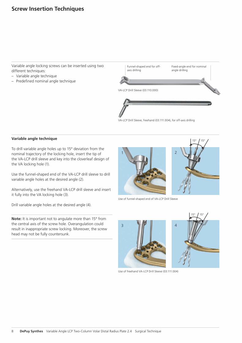
Use of funnel-shaped end of VA-LCP Drill Sleeve
Use of freehand VA-LCP Drill Sleeve (03.111.004)
Screw Insertion Techniques
VA-LCP Drill Sleeve (03.110.000)
VA-LCP Drill Sleeve, freehand (03.111.004), for off-axis drilling
Funnel-shaped end for off-axis drilling
Fixed-angle end for nominal angle drilling
Variable angle locking screws can be inserted using two different techniques: – Variable angle technique – Predefi ned nominal angle technique
Variable angle technique
To drill variable angle holes up to 15° deviation from the nominal trajectory of the locking hole, insert the tip of the VA-LCP drill sleeve and key into the cloverleaf design of the VA locking hole (1).
Use the funnel-shaped end of the VA-LCP drill sleeve to drill variable angle holes at the desired angle (2).
Alternatively, use the freehand VA-LCP drill sleeve and insert it fully into the VA locking hole (3).
Drill variable angle holes at the desired angle (4).
Note: It is important not to angulate more than 15° from the central axis of the screw hole. Overangulation could result in inappropriate screw locking. Moreover, the screw head may not be fully countersunk.
Variable Angle LCP Two-Column Volar Distal Radius Plate 2.4 Surgical Technique DePuy Synthes 9
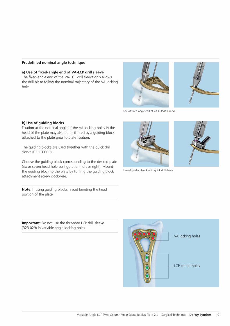
Use of fixed-angle end of VA-LCP drill sleeve
Use of guiding block with quick drill sleeve
Predefined nominal angle technique
a) Use of fixed-angle end of VA-LCP drill sleeveThe fixed-angle end of the VA-LCP drill sleeve only allows the drill bit to follow the nominal trajectory of the VA locking hole.
b) Use of guiding blocksFixation at the nominal angle of the VA locking holes in the head of the plate may also be facilitated by a guiding block attached to the plate prior to plate fixation.
The guiding blocks are used together with the quick drill sleeve (03.111.000).
Choose the guiding block corresponding to the desired plate (six or seven head hole configuration, left or right). Mount the guiding block to the plate by turning the guiding block attachment screw clockwise.
Note: If using guiding blocks, avoid bending the head portion of the plate.
VA locking holes
LCP combi-holes
Important: Do not use the threaded LCP drill sleeve (323.029) in variable angle locking holes.
10 DePuy Synthes Variable Angle LCP Two-Column Volar Distal Radius Plate 2.4 Surgical Technique
distal 27°radial 2°
distal 30°radial 10°
distal 33°radial 15°
distal 23°ulnar 2°
Reference point: 0°
distal 20°ulnar 3°
distal 23°ulnar 1°
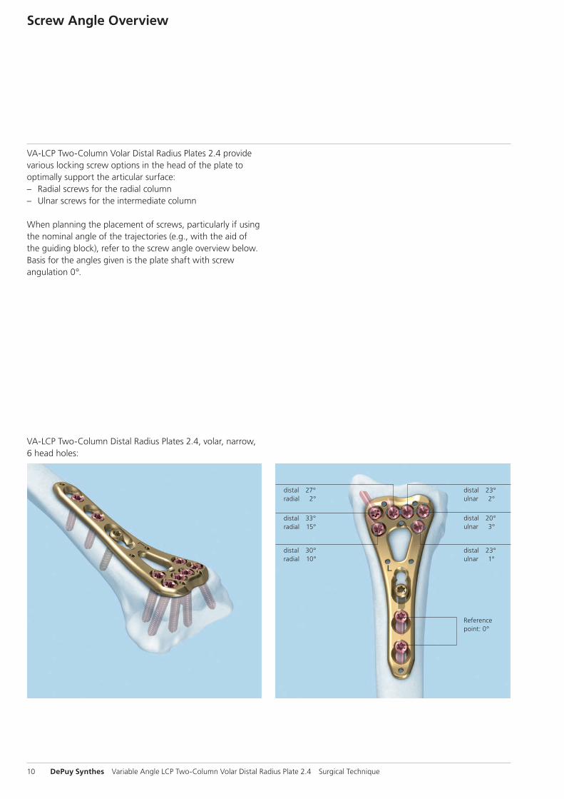
Screw Angle Overview
VA-LCP Two-Column Volar Distal Radius Plates 2.4 provide various locking screw options in the head of the plate to optimally support the articular surface: – Radial screws for the radial column – Ulnar screws for the intermediate column
When planning the placement of screws, particularly if using the nominal angle of the trajectories (e.g., with the aid of the guiding block), refer to the screw angle overview below. Basis for the angles given is the plate shaft with screw angulation 0°.
VA-LCP Two-Column Distal Radius Plates 2.4, volar, narrow, 6 head holes:

Variable Angle LCP Two-Column Volar Distal Radius Plate 2.4 Surgical Technique DePuy Synthes 11
distal 30°radial 6°
distal 30°radial 10°
distal 33°radial 15°
distal 19°ulnar 4°
Reference point: 0°
distal 16°ulnar 4°
distal 23°ulnar 1°
distal 25°radial 0°
distal 27°radial 5°
distal 30°radial 9°
distal 33°radial 15°
distal 21°ulnar 1°
Reference point: 0°
distal 14°ulnar 6°
distal 23°ulnar 1°
VA-LCP Two-Column Distal Radius Plates 2.4, 7 head holes:
VA-LCP Two-Column Distal Radius Plates 2.4, volar, 6 head holes:

12 DePuy Synthes Variable Angle LCP Two-Column Volar Distal Radius Plate 2.4 Surgical Technique
Make a longitudinal incision slightly radial to the flexor carpi radialis tendon (FCR). Dissect between the FCR and the radial artery, exposing the pronator quadratus. Detach the prona-tor quadratus from the lateral border of the radius and ele-vate it toward the ulna.
Important: Leave the volar wrist capsule intact to avoid devascularization of the fracture fragments and destabiliza-tion of the volar wrist ligaments.
Approach
Variable Angle LCP Two-Column Volar Distal Radius Plate 2.4 Surgical Technique DePuy Synthes 13
Implantation
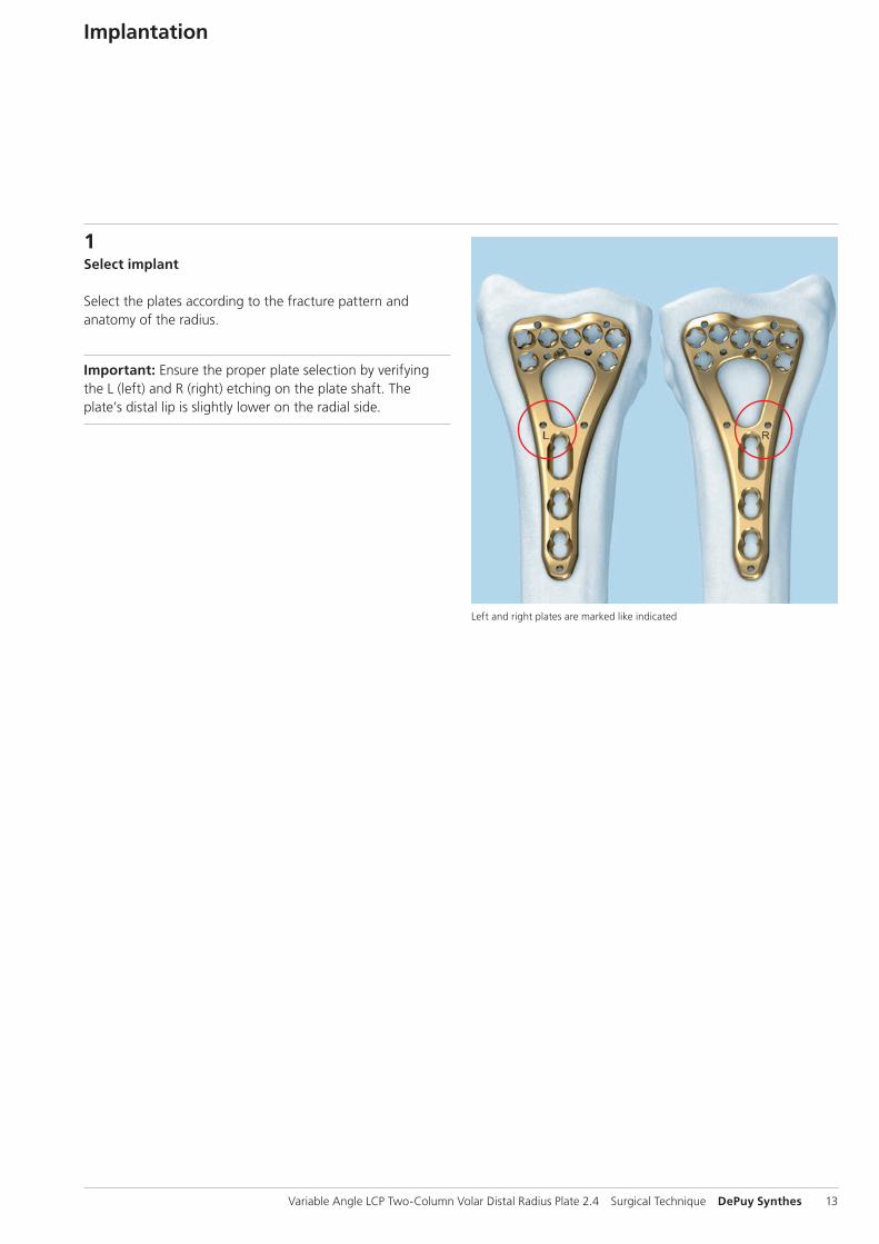
1Select implant
Select the plates according to the fracture pattern and anatomy of the radius.
Important: Ensure the proper plate selection by verifying the L (left) and R (right) etching on the plate shaft. The plate’s distal lip is slightly lower on the radial side.
Left and right plates are marked like indicated
14 DePuy Synthes Variable Angle LCP Two-Column Volar Distal Radius Plate 2.4 Surgical Technique
2Reduce fracture and position plate
Instruments for 2.4 mm and 2.7 mm cortex screws
310.509 Drill Bit B 1.8 mm, with marking, length 110/85 mm, 2-flute, for Quick Coupling
310.534 Drill Bit B 2.0 mm, with marking, length 110/85 mm, 2-flute, for Quick Coupling
323.202 Universal Drill Guide 2.4
323.260 Universal Drill Guide 2.7
311.430 Handle with Quick Coupling, length 110 mm
314.453 Screwdriver Shaft, Stardrive, T8, short, self-holding
03.111.005 Depth Gauge for Screws B 2.4 to 2.7 mm, measuring range up to 40 mm
Implantation
Variable Angle LCP Two-Column Volar Distal Radius Plate 2.4 Surgical Technique DePuy Synthes 15
Optional
314.467 Screwdriver Shaft, Stardrive, T8, self-holding
292.120 Kirschner Wire B 1.25 mm with trocar tip, length 150 mm, Stainless Steel
02.111.500.01(S) Plate Reduction Wire B 1.25 mm, with thread, with Small Stop, length 150 mm, Stainless Steel
02.111.501.01(S) Plate Reduction Wire B 1.25 mm, with thread, with Large Stop, length 150 mm, Stainless Steel

16 DePuy Synthes Variable Angle LCP Two-Column Volar Distal Radius Plate 2.4 Surgical Technique
Implantation
Reduce the fracture. The reduction method will be frac-ture-specific.
Apply the plate to fit the volar surface.
If necessary, use 1.25 mm Kirschner wires inserted through the desired Kirschner wire hole to temporarily fix the plate distally.
The order of screw insertion and the use of Kirschner wires may vary depending on the fracture pattern and reduction technique.
Perform several radiographic views of the distal radius to ensure alignment and reduction.
Additional options for preliminary Kirschner wire fixation
Option: Plate reduction wires
The 1.25 mm plate reduction wires can be used for prelimi-nary plate fixation. They must be removed when not needed for temporary fixation anymore.
Note: The plate reduction wires and Kirschner wires are single use items, do not re-use.
Variable Angle LCP Two-Column Volar Distal Radius Plate 2.4 Surgical Technique DePuy Synthes 17
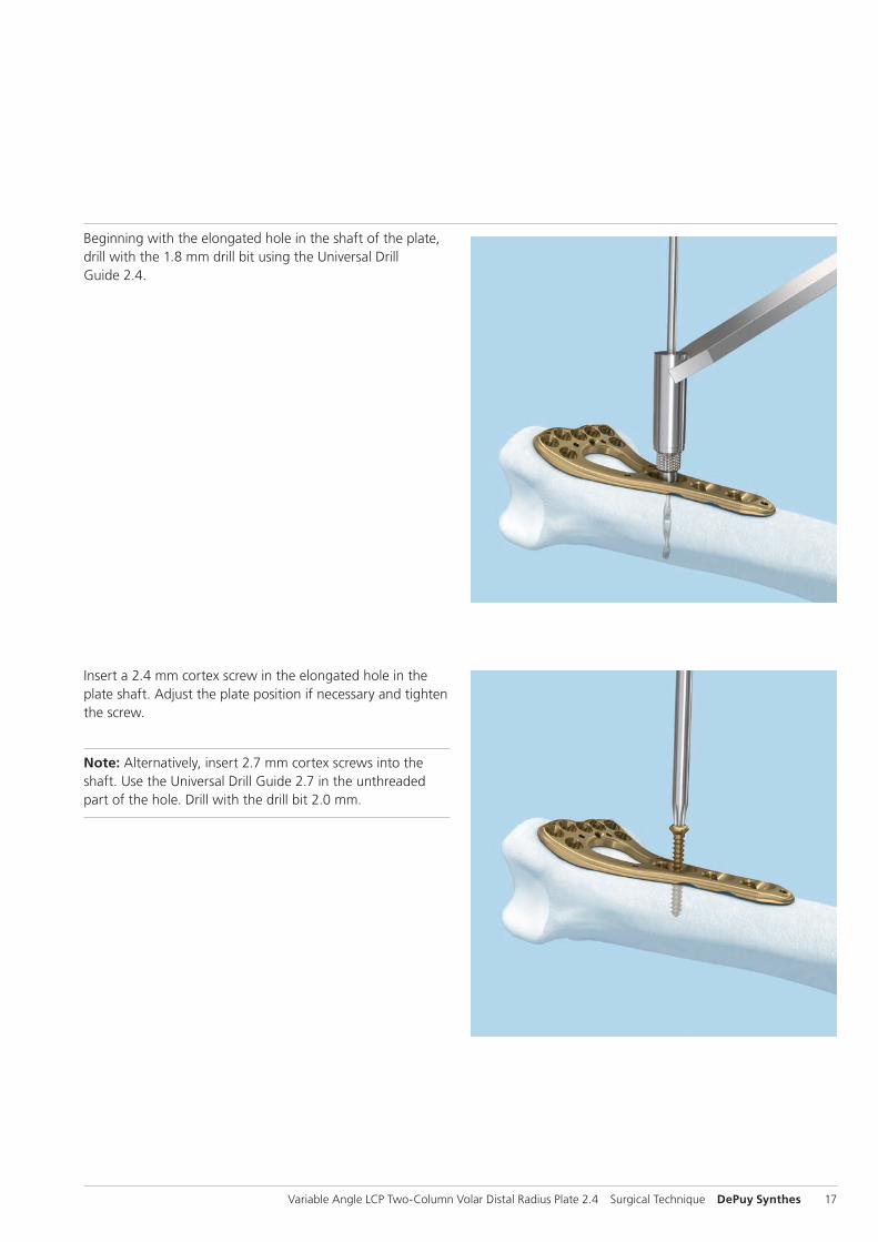
Insert a 2.4 mm cortex screw in the elongated hole in the plate shaft. Adjust the plate position if necessary and tighten the screw.
Note: Alternatively, insert 2.7 mm cortex screws into the shaft. Use the Universal Drill Guide 2.7 in the unthreaded part of the hole. Drill with the drill bit 2.0 mm.
Beginning with the elongated hole in the shaft of the plate, drill with the 1.8 mm drill bit using the Universal Drill Guide 2.4.
18 DePuy Synthes Variable Angle LCP Two-Column Volar Distal Radius Plate 2.4 Surgical Technique
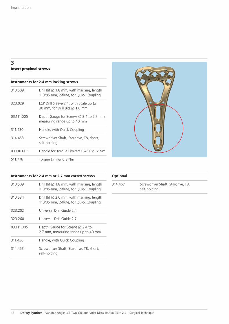
3Insert proximal screws
Instruments for 2.4 mm locking screws
310.509 Drill Bit B 1.8 mm, with marking, length 110/85 mm, 2-flute, for Quick Coupling
323.029 LCP Drill Sleeve 2.4, with Scale up to 30 mm, for Drill Bits B 1.8 mm
03.111.005 Depth Gauge for Screws B 2.4 to 2.7 mm, measuring range up to 40 mm
311.430 Handle, with Quick Coupling
314.453 Screwdriver Shaft, Stardrive, T8, short, self-holding
03.110.005 Handle for Torque Limiters 0.4/0.8/1.2 Nm
511.776 Torque Limiter 0.8 Nm
Instruments for 2.4 mm or 2.7 mm cortex screws
310.509 Drill Bit B 1.8 mm, with marking, length 110/85 mm, 2-flute, for Quick Coupling
310.534 Drill Bit B 2.0 mm, with marking, length 110/85 mm, 2-flute, for Quick Coupling
323.202 Universal Drill Guide 2.4
323.260 Universal Drill Guide 2.7
03.111.005 Depth Gauge for Screws B 2.4 to 2.7 mm, measuring range up to 40 mm
311.430 Handle, with Quick Coupling
314.453 Screwdriver Shaft, Stardrive, T8, short, self-holding
Implantation
Optional
314.467 Screwdriver Shaft, Stardrive, T8, self-holding
Variable Angle LCP Two-Column Volar Distal Radius Plate 2.4 Surgical Technique DePuy Synthes 19
Determine where 2.4 mm locking screws and 2.4 mm or 2.7 mm cortex screws will be used in the shaft of the plate. Insert the screws, beginning with the most proximal screw.
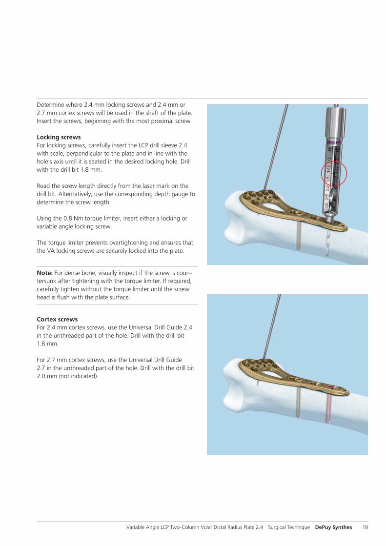
Locking screwsFor locking screws, carefully insert the LCP drill sleeve 2.4with scale, perpendicular to the plate and in line with the hole’s axis until it is seated in the desired locking hole. Drill with the drill bit 1.8 mm.
Read the screw length directly from the laser mark on thedrill bit. Alternatively, use the corresponding depth gauge to determine the screw length.
Using the 0.8 Nm torque limiter, insert either a locking or variable angle locking screw.
The torque limiter prevents overtightening and ensures that the VA locking screws are securely locked into the plate.
Note: For dense bone, visually inspect if the screw is coun-tersunk after tightening with the torque limiter. If required, carefully tighten without the torque limiter until the screw head is flush with the plate surface.
Cortex screwsFor 2.4 mm cortex screws, use the Universal Drill Guide 2.4 in the unthreaded part of the hole. Drill with the drill bit 1.8 mm.
For 2.7 mm cortex screws, use the Universal Drill Guide 2.7 in the unthreaded part of the hole. Drill with the drill bit 2.0 mm (not indicated).

20 DePuy Synthes Variable Angle LCP Two-Column Volar Distal Radius Plate 2.4 Surgical Technique
4Drill screw hole for VA locking screws
Instruments
310.509 Drill Bit B 1.8 mm, with marking, length 110/85 mm, 2-flute, for Quick Coupling
03.111.005 Depth Gauge for Screws B 2.4 to 2.7 mm, measuring range up to 40 mm
Determine whether screws will be inserted at a variable angle (4a) or at the predefined nominal angle (4b).
Implantation

15° 15°
Variable Angle LCP Two-Column Volar Distal Radius Plate 2.4 Surgical Technique DePuy Synthes 21
4aDrill screw hole for VA locking screw using variable angle technique
Instrument
03.110.000 VA-LCP Drill Sleeve 2.4, for Drill Bits B 1.8 mm
Optional
03.110.023 VA-LCP Drill Sleeve 2.4, conical, for Drill Bits B 1.8 mm
03.111.004 VA-LCP Drill Sleeve 2.4, for Drill Bits B 1.8 mm, freehand usable
Drill using VA-LCP drill sleeve with funnelInsert and lock the VA-LCP drill sleeve tip into the cloverleaf design of the VA locking hole.
Use the 1.8 mm drill bit to drill to the desired depth at the desired angle.
The funnel of the drill sleeve allows the drill bit up to a 15° angulation around the central axis of the locking hole.
15° 15°
22 DePuy Synthes Variable Angle LCP Two-Column Volar Distal Radius Plate 2.4 Surgical Technique
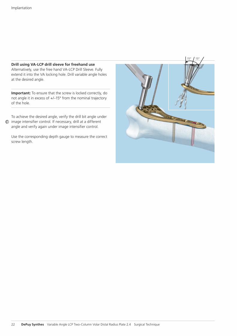
Drill using VA-LCP drill sleeve for freehand useAlternatively, use the free hand VA-LCP Drill Sleeve. Fully extend it into the VA locking hole. Drill variable angle holes at the desired angle.
Important: To ensure that the screw is locked correctly, do not angle it in excess of +/–15° from the nominal trajectory of the hole.
To achieve the desired angle, verify the drill bit angle under image intensifier control. If necessary, drill at a different angle and verify again under image intensifier control.
Use the corresponding depth gauge to measure the correct screw length.
Implantation
Variable Angle LCP Two-Column Volar Distal Radius Plate 2.4 Surgical Technique DePuy Synthes 23
4bDrill using predefined nominal angle technique
Instrument
03.110.000 VA-LCP Drill Sleeve 2.4, for Drill Bits B 1.8 mm
Optional
03.110.024 VA-LCP Drill Sleeve 2.4, coaxial, for Drill Bits B 1.8 mm
03.111.000 Quick Drill Sleeve 2.4 with Scale, for Drill Bits B 1.8 mm, for Guiding Block
03.111.500 Guiding Block for Two-Column Distal Radius Plate 2.4, narrow, 6 holes, right
03.111.501 Guiding Block for Two-Column Distal Radius Plate 2.4, narrow, 6 holes, left
03.111.600 Guiding Block for Two-Column Distal Radius Plate 2.4, 6 holes, right
03.111.601 Guiding Block for Two-Column Distal Radius Plate 2.4, 6 holes, left
03.111.700 Guiding Block for Two-Column Distal Radius Plate 2.4, 7 holes, right
03.111.701 Guiding Block for Two-Column Distal Radius Plate 2.4, 7 holes, left
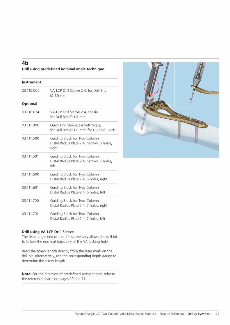
Drill using VA-LCP Drill SleeveThe fixed-angle end of the drill sleeve only allows the drill bit to follow the nominal trajectory of the VA locking hole.
Read the screw length directly from the laser mark on the drill bit. Alternatively, use the corresponding depth gauge to determine the screw length.
Note: For the direction of predefined screw angles, refer to the reference charts on pages 10 and 11.
24 DePuy Synthes Variable Angle LCP Two-Column Volar Distal Radius Plate 2.4 Surgical Technique
Implantation
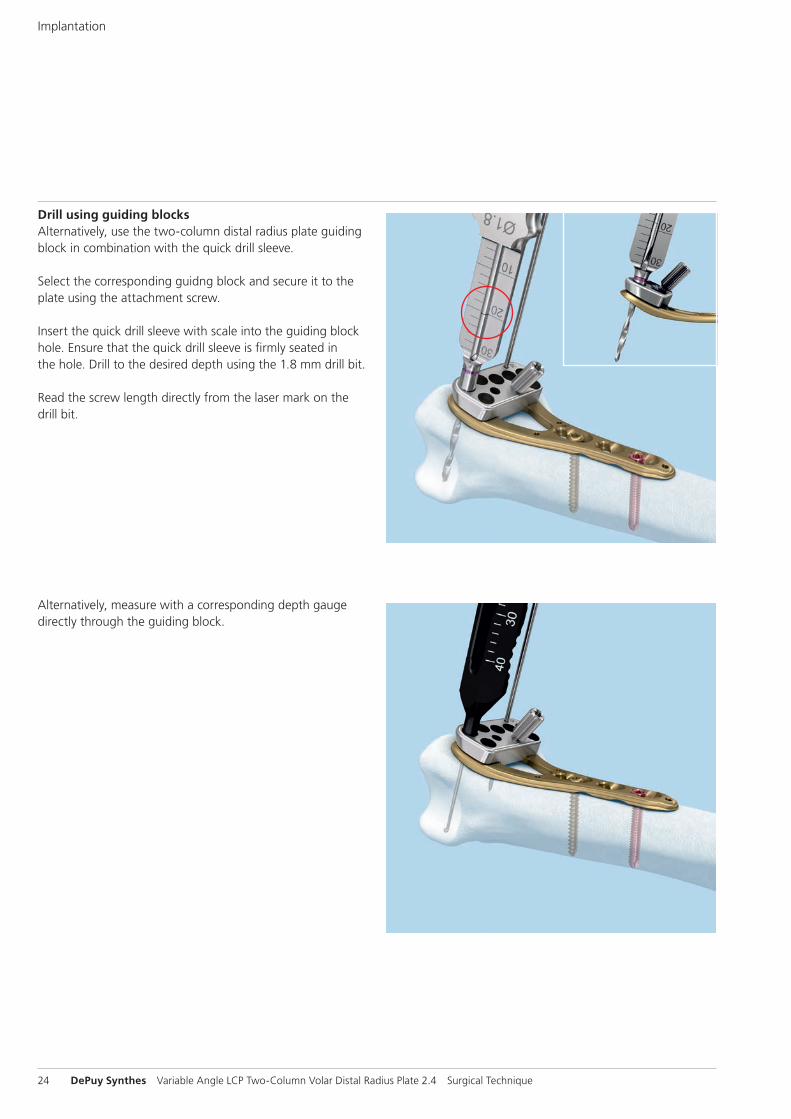
Drill using guiding blocksAlternatively, use the two-column distal radius plate guiding block in combination with the quick drill sleeve.
Select the corresponding guidng block and secure it to the plate using the attachment screw.
Insert the quick drill sleeve with scale into the guiding block hole. Ensure that the quick drill sleeve is firmly seated in the hole. Drill to the desired depth using the 1.8 mm drill bit.
Read the screw length directly from the laser mark on the drill bit.
Alternatively, measure with a corresponding depth gauge directly through the guiding block.

1
2
Variable Angle LCP Two-Column Volar Distal Radius Plate 2.4 Surgical Technique DePuy Synthes 25
5Insert VA locking screws
Instruments
311.430 Handle with Quick Coupling, length 110 mm
314.453 Screwdriver Shaft, Stardrive, T8, short, self-holding
Optional
314.467 Screwdriver Shaft, Stardrive, T8, self-holding
Insert the VA locking screws manually with the self retaining T8 Stardrive screwdriver shaft and quick coupling handle and tighten just enough for the screw head to be fully seated in the VA locking hole (1).
Do not over-tighten the screw. This allows the screws to be easily removed should they not be in the desired position.
Technique tip: When a guiding block is used, the locking screw (VA locking or standard locking) may be inserted with a T8 screwdriver directly through the guiding block (2).
26 DePuy Synthes Variable Angle LCP Two-Column Volar Distal Radius Plate 2.4 Surgical Technique
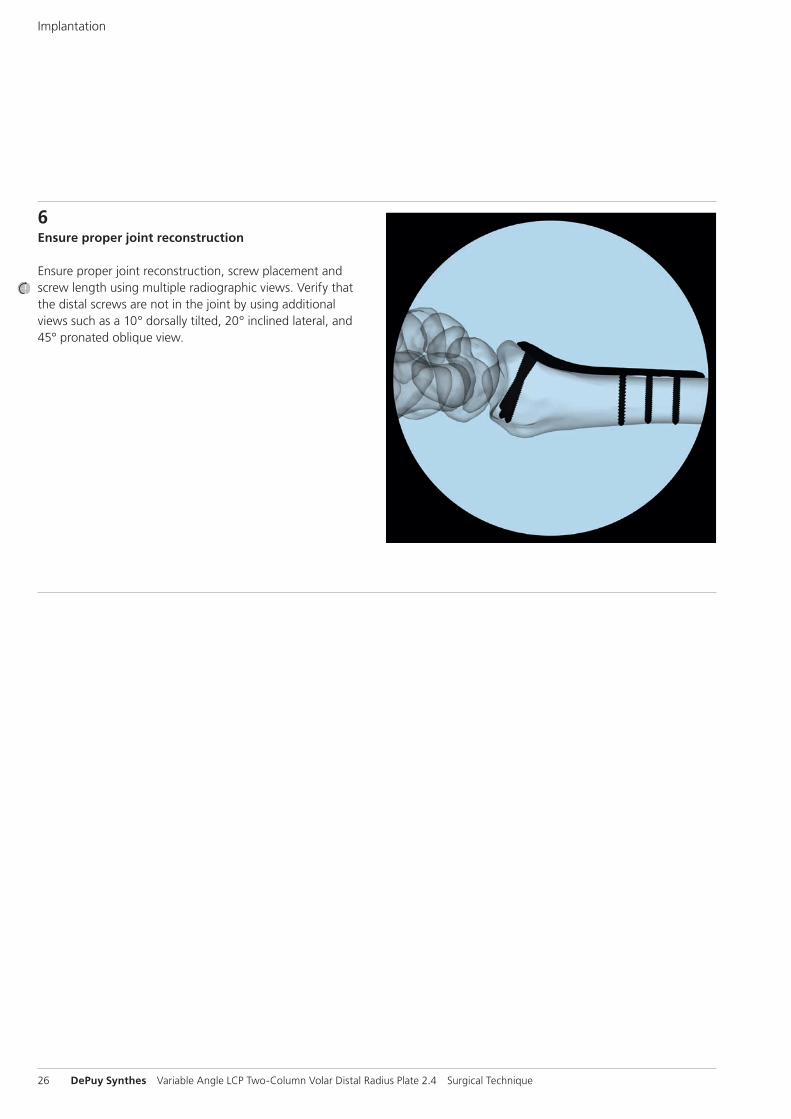
6Ensure proper joint reconstruction
Ensure proper joint reconstruction, screw placement and screw length using multiple radiographic views. Verify that the distal screws are not in the joint by using additional views such as a 10° dorsally tilted, 20° inclined lateral, and 45° pronated oblique view.
Implantation
Variable Angle LCP Two-Column Volar Distal Radius Plate 2.4 Surgical Technique DePuy Synthes 27
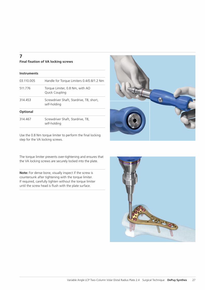
7Final fixation of VA locking screws
Instruments
03.110.005 Handle for Torque Limiters 0.4/0.8/1.2 Nm
511.776 Torque Limiter, 0.8 Nm, with AO Quick Coupling
314.453 Screwdriver Shaft, Stardrive, T8, short, self-holding
Optional
314.467 Screwdriver Shaft, Stardrive, T8, self-holding
Use the 0.8 Nm torque limiter to perform the final locking step for the VA locking screws.
The torque limiter prevents over-tightening and ensures that the VA locking screws are securely locked into the plate.
Note: For dense bone, visually inspect if the screw is counter sunk after tightening with the torque limiter. If required, carefully tighten without the torque limiter until the screw head is flush with the plate surface.

28 DePuy Synthes Variable Angle LCP Two-Column Volar Distal Radius Plate 2.4 Surgical Technique
Postoperative treatment
Postoperative treatment with VA locking compression plates does not differ from conventional internal fixation proce-dures.
Implant removal
Instruments
311.430 Handle with Quick Coupling
314.453 Screwdriver Shaft Stardrive 2.4, short, self-holding, for Quick Coupling
Optional
314.467 Screwdriver Shaft Stardrive‚ T8, self-holding
314.468 Holding Sleeve for Screws Stardrive B 2.4 mm, T8, for Screwdriver Shaft 314.467
To remove locking screws, first unlock all screws from the plate; then remove the screws completely from the bone.
The last screw removed should be a non-locking screw on the shaft. This prevents the plate from spinning when locking screws are removed.
Postoperative Treatment/Implant Removal
Variable Angle LCP Two-Column Volar Distal Radius Plate 2.4 Surgical Technique DePuy Synthes 29
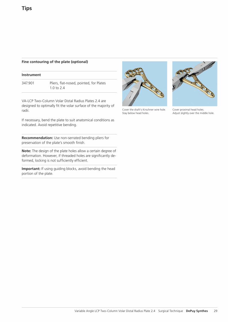
Cover the shaft’s Kirschner wire hole. Stay below head holes.
Cover proximal head holes. Adjust slightly over the middle hole.
Tips
Fine contouring of the plate (optional)
Instrument
347.901 Pliers, flat-nosed, pointed, for Plates 1.0 to 2.4
VA-LCP Two-Column Volar Distal Radius Plates 2.4 are designed to optimally fit the volar surface of the majority of radii.
If necessary, bend the plate to suit anatomical conditions as indicated. Avoid repetitive bending.
Recommendation: Use non-serrated bending pliers for preservation of the plate’s smooth finish.
Note: The design of the plate holes allow a certain degree of deformation. However, if threaded holes are significantly de-formed, locking is not sufficiently efficient.
Important: If using guiding blocks, avoid bending the head portion of the plate.

30 DePuy Synthes Variable Angle LCP Two-Column Volar Distal Radius Plate 2.4 Surgical Technique
VA-LCP Two-Column Distal Radius Plates 2.4,volar, 6 holes, width 22 mm
Part Head Shaft Length Left/Rightnumber holes holes mm
0X.111.620 6 2 45 R
0X.111.621 6 2 45 L
0X.111.630 6 3 54 R
0X.111.631 6 3 54 L
0X.111.640 6 4 66 R
0X.111.641 6 4 66 L
0X.111.650 6 5 75 R
0X.111.651 6 5 75 L
All plates are available non-sterile and sterile packed. Add suffix “S” to article number to order sterile product.
X = 2: Stainless SteelX = 4: TiCP
Right, wide
Right, standard
VA-LCP Two-Column Distal Radius Plates 2.4,volar, 7 holes, width 25.5 mm
Part Head Shaft Length Left/Rightnumber holes holes mm
0X.111.720 7 2 47 R
0X.111.721 7 2 47 L
0X.111.730 7 3 55 R
0X.111.731 7 3 55 L
0X.111.740 7 4 68 R
0X.111.741 7 4 68 L
0X.111.750 7 5 77 R
0X.111.751 7 5 77 L
VA-LCP Two-Column Distal Radius Plates 2.4,volar, narrow, 6 holes, width 19.5 mm
Part Head Shaft Length Left/Rightnumber holes holes mm
0X.111.520 6 2 42 R
0X.111.521 6 2 42 L
0X.111.530 6 3 51 R
0X.111.531 6 3 51 L
0X.111.540 6 4 63 R
0X.111.541 6 4 63 L
0X.111.550 6 5 72 R
0X.111.551 6 5 72 L
Right, narrow
Plates

Variable Angle LCP Two-Column Volar Distal Radius Plate 2.4 Surgical Technique DePuy Synthes 31
Screws
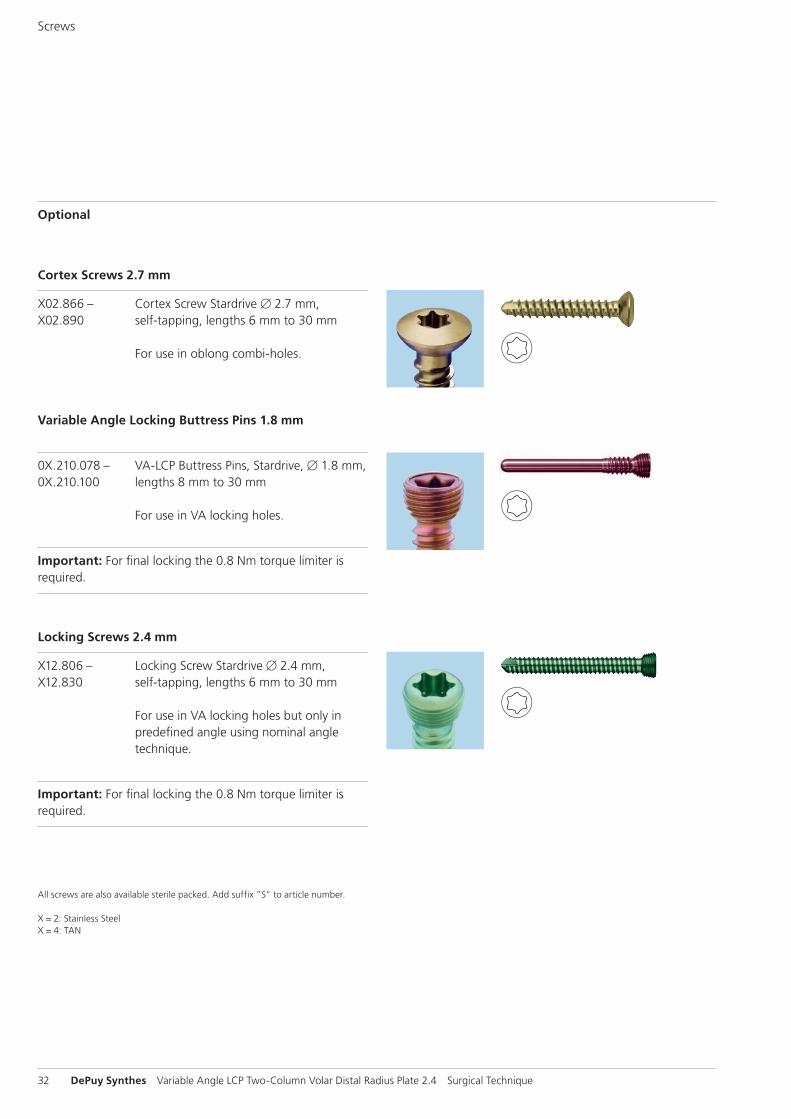
Cortex Screws 2.4 mm
X01.756 – Cortex Screw Stardrive B 2.4 mm, X01.780 self-tapping, lengths 6 mm to 30 mm
For use in VA locking holes or oblong combi-holes.
Variable Angle Locking Screws 2.4 mm
0X.210.108 – VA Locking Screw Stardrive B 2.4 mm,0X.210.130 self-tapping, lengths 8 mm to 30 mm
For use in VA locking holes.
Important: For final locking the 0.8 Nm torque limiter is required.
32 DePuy Synthes Variable Angle LCP Two-Column Volar Distal Radius Plate 2.4 Surgical Technique
Variable Angle Locking Buttress Pins 1.8 mm
0X.210.078 – VA-LCP Buttress Pins, Stardrive, B 1.8 mm,0X.210.100 lengths 8 mm to 30 mm
For use in VA locking holes.
Important: For final locking the 0.8 Nm torque limiter is required.
Locking Screws 2.4 mm
X12.806 – Locking Screw Stardrive B 2.4 mm, X12.830 self-tapping, lengths 6 mm to 30 mm
For use in VA locking holes but only in predefined angle using nominal angle technique.
Important: For final locking the 0.8 Nm torque limiter is required.
All screws are also available sterile packed. Add suffix ”S” to article number.
X = 2: Stainless SteelX = 4: TAN
Cortex Screws 2.7 mm
X02.866 – Cortex Screw Stardrive B 2.7 mm,X02.890 self-tapping, lengths 6 mm to 30 mm
For use in oblong combi-holes.
Optional
Screws
Variable Angle LCP Two-Column Volar Distal Radius Plate 2.4 Surgical Technique DePuy Synthes 33
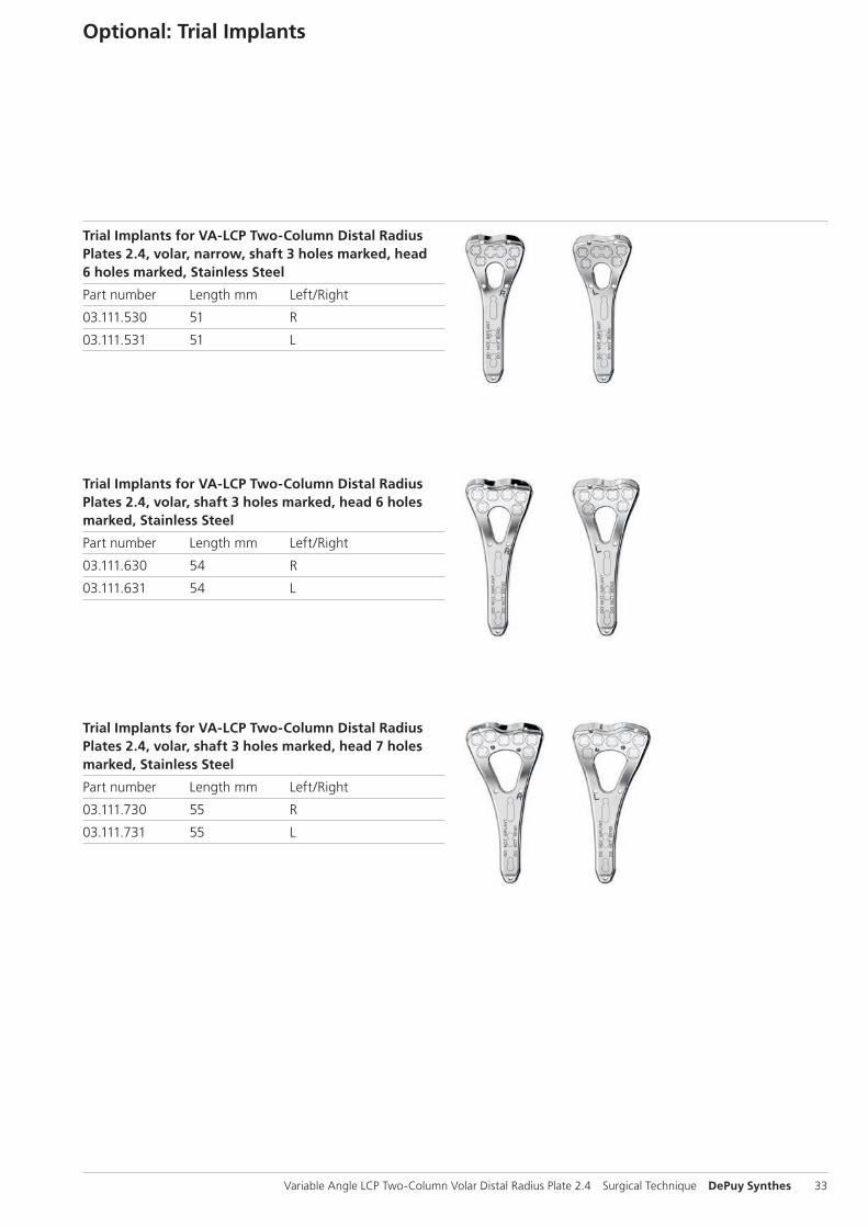
Optional: Trial Implants
Trial Implants for VA-LCP Two-Column Distal Radius Plates 2.4, volar, narrow, shaft 3 holes marked, head 6 holes marked, Stainless Steel
Part number Length mm Left/Right
03.111.530 51 R
03.111.531 51 L
Trial Implants for VA-LCP Two-Column Distal Radius Plates 2.4, volar, shaft 3 holes marked, head 6 holes marked, Stainless Steel
Part number Length mm Left/Right
03.111.630 54 R
03.111.631 54 L
Trial Implants for VA-LCP Two-Column Distal Radius Plates 2.4, volar, shaft 3 holes marked, head 7 holes marked, Stainless Steel
Part number Length mm Left/Right
03.111.730 55 R
03.111.731 55 L
34 DePuy Synthes Variable Angle LCP Two-Column Volar Distal Radius Plate 2.4 Surgical Technique
Instruments
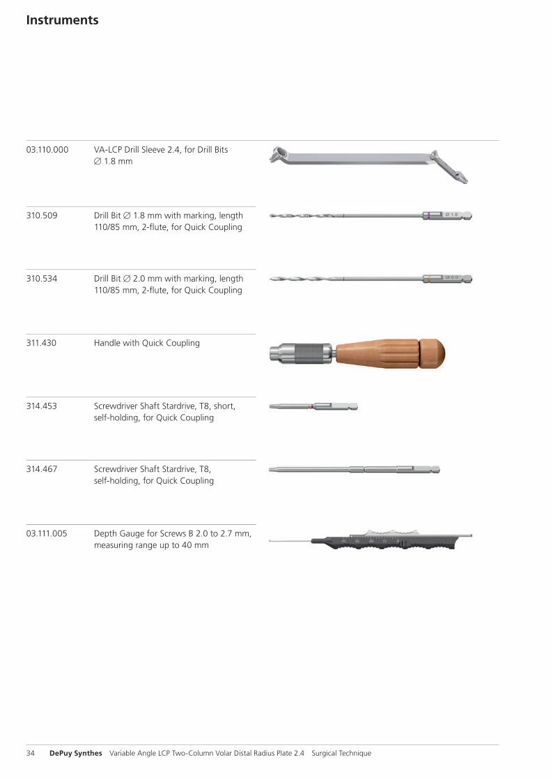
03.110.000 VA-LCP Drill Sleeve 2.4, for Drill Bits B 1.8 mm
310.509 Drill Bit B 1.8 mm with marking, length 110/85 mm, 2-fl ute, for Quick Coupling
310.534 Drill Bit B 2.0 mm with marking, length 110/85 mm, 2-fl ute, for Quick Coupling
311.430 Handle with Quick Coupling
314.453 Screwdriver Shaft Stardrive, T8, short, self-holding, for Quick Coupling
314.467 Screwdriver Shaft Stardrive‚ T8, self-holding, for Quick Coupling
03.111.005 Depth Gauge for Screws B 2.0 to 2.7 mm, measuring range up to 40 mm

Variable Angle LCP Two-Column Volar Distal Radius Plate 2.4 Surgical Technique DePuy Synthes 35
323.029 LCP Drill Sleeve 2.4, with Scale up to 30 mm, for Drill Bits B 1.8 mm
323.202 Universal Drill Guide 2.4
323.260 Universal Drill Guide 2.7
03.110.005 Handle for Torque Limiters 0.4/0.8/1.2 Nm
511.776 Torque Limiter 0.8 Nm, with Quick Coupling
292.120(S) Kirschner Wire B 1.25 mm with trocar tip, length 150 mm, Stainless Steel

36 DePuy Synthes Variable Angle LCP Two-Column Volar Distal Radius Plate 2.4 Surgical Technique
Instruments
Optional instruments
03.110.023 VA-LCP Drill Sleeve 2.4, conical, for Drill Bits B 1.8 mm
03.110.024 VA-LCP Drill Sleeve 2.4, coaxial, for Drill Bits B 1.8 mm
03.111.004 VA-LCP Drill Sleeve 2.4, for Drill Bits B 1.8 mm, freehand useable
03.111.000 Quick Drill Sleeve 2.4 with Scale, for Drill Bits B 1.8 mm, for Guiding Block, for VA-LCP Radius Plates
02.111.500.01(S) Plate Reduction Wire B 1.25 mm, with thread, with Small Stop, length 150 mm, Stainless Steel
02.111.501.01(S) Plate Reduction Wire B 1.25 mm, with thread, with Large Stop, length 150 mm, Stainless Steel

Variable Angle LCP Two-Column Volar Distal Radius Plate 2.4 Surgical Technique DePuy Synthes 37
03.111.600 Guiding Block for Two-Column Distal Radius Plate 2.4, 6 holes, right
03.111.601 Guiding Block for Two-Column Distal Radius Plate 2.4, 6 holes, left
03.111.700 Guiding Block for Two-Column Distal Radius Plate 2.4, 7 holes, right
03.111.007 Screw for Guiding Block for Two-Column Distal Radius Plate 2.4
03.111.701 Guiding Block for Two-Column Distal Radius Plate 2.4, 7 holes, left
03.111.500 Guiding Block for Two-Column Distal Radius Plate 2.4, narrow, 6 holes, right
03.111.501 Guiding Block for Two-Column Distal Radius Plate 2.4, narrow, 6 holes, left
314.468 Holding Sleeve for Screws Stardrive B 2.4 mm, T8, for Screwdriver Shaft 314.467
38 DePuy Synthes Variable Angle LCP Two-Column Volar Distal Radius Plate 2.4 Surgical Technique
Bibliography
Arora R, Lutz M, Fritz D, Zimmermann R, Oberladstätter J, Gabl M (2005) Palmar locking plate for treatment of unsta-ble dorsal dislocated distal radius fractures. Arch Orthop Trauma Surg 125:399–404
Cassidy C, Jupiter J, Cohen M, Delli-Santi M, Fennell C, Lein-berry C, Husband J, Ladd A, Seitz W and Constanz B (2003) Norian SRS Cement compared with conventional fixation in distal radius fractures – A randomised study. JBJS Vol 85-A, Nr 11, Nov 2003
Chen CC, Jupiter JB (2007) Management of Distal Radius Fractures. J Bone Joint Surg [Am] 89:2051–2062
Fernandez DL (2000) Distal Radius and Wrist. In: Rüedi TP, Murphy WM (editors) AO principles of fracture management. Thieme, Stuttgart New York:355–377
Hems TE, Davidson H, Nicol AC, Mansbridge D (2000) Open reduction and plate fixation of unstable fractures of the dis-tal radius: A biomechanical analysis and clinical experience. J Bone Joint Surg [Br] 82:83
Jakob M, RikIi DA, Regazzoni P (2000) Fractures of the distal radius treated by internal fixation and early function: A pro-spective study of 73 consecutive patients. J Bone Joint Surg [Br] 82:340–344
Jupiter JB, Ring D (2005) AO Manual of Fracture Manage-ment – Hand and Wrist. Thieme, Stuttgart New York
Jupiter JB, Marent-Huber M; LCP Study Group (2009) Operative management of distal radius fractures with 2.4-millimeter locking plates. A multicenter prospective case series. J Bone Joint Surg [AM] 09(1): 55-56
Mudgal CS, Jupiter JB (2008) Plate fixation of osteoporotic fractures of the distal radius. J Orthop Trauma 22(8):106–115
Nijs S, Broos PLO (2004) Fractures of the distal radius: A Contemporary Approach. Acta Chir Belg 104:401–404

Variable Angle LCP Two-Column Volar Distal Radius Plate 2.4 Surgical Technique DePuy Synthes 39
Rausch S, Hoffmeier K, Gueorguiev BG, Klos K, Gras F, Hofmann GO, Mückley T (2011) Comparative Study on the Strength of Different Mechanisms of Operation of Multi-directionally Angle-Stable Distal Radius Plates. Z Orthop Unfall 149:694– 698
Rikli DA, Honigmann P, Babst R, Cristalli A, Morlock MM, Mittlmeier T (2007) Intra-Articular Pressure Measurement in the Radioulnocarpal Joint Using a Novel Sensor: In Vitro and In Vivo Results, J Hand Surg 32A:67–75
Rikli DA, Regazzoni P (1996) Fractures of the distal end of the radius treated by internal fixation and early function. A preliminary report of 20 cases. J Bone Joint Surg [Br] 78 (4): 588–592
Rikli DA, Regazzoni P (2000) The double plating technique for distal radius fractures. Techniques in hand and upper extremity surgery 4:101–114
Ring D, Prommersberger K, Jupiter JB (2004) Combined dor-sal and volar plate fixation of complex fractures of the distal part of the radius. J Bone Surg [Am] 86:1646 –1652
Zimmerman R, Gabl M, Lutz M, Angermann P, Gschwenter M and Pechlaner S (2003) Injectable calcium phosphate bone cement Norian SRS for the treatment of intra-articular com-pression fractures of the distal radius in osteoporotic women. Arch Orthop Trauma Surg 123:22–27

40 DePuy Synthes Variable Angle LCP Two-Column Volar Distal Radius Plate 2.4 Surgical Technique
MRI Information
Torque, Displacement and Image Artifacts according to ASTM F 2213-06, ASTM F 2052-06e1 and ASTM F2119-07Non-clinical testing of worst case scenario in a 3 T MRI system did not reveal any relevant torque or displacement of the construct for an experimentally measured local spatial gradient of the magnetic field of 3.69 T/m. The largest image artifact extended approximately 169 mm from the construct when scanned using the Gradient Echo (GE). Testing was conducted on a 3 T MRI system.
Radio-Frequency-(RF-)induced heating according to ASTM F2182-11aNon-clinical electromagnetic and thermal testing of worst case scenario lead to peak temperature rise of 9.5 °C with an average temperature rise of 6.6 °C (1.5 T) and a peak temperature rise of 5.9 °C (3 T) under MRI Conditions using RF Coils [whole body averaged specific absorption rate (SAR) of 2 W/kg for 6 minutes (1.5 T) and for 15 minutes (3 T)].
Precautions: The above mentioned test relies on non-clini-cal testing. The actual temperature rise in the patient will depend on a variety of factors beyond the SAR and time of RF application. Thus, it is recommended to pay particular attention to the following points: – It is recommended to thoroughly monitor patients under-
going MR scanning for perceived temperature and/or pain sensations.
– Patients with impaired thermo regulation or temperature sensation should be excluded from MR scanning proce-dures.
– Generally it is recommended to use a MR system with low field strength in the presence of conductive implants. The employed specific absorption rate (SAR) should be reduced as far as possible.
– Using the ventilation system may further contribute to reduce temperature increase in the body.


0123
Synthes GmbHEimattstrasse 34436 OberdorfSwitzerlandTel: +41 61 965 61 11Fax: +41 61 965 66 00www.depuysynthes.com
This publication is not intended for distribution in the USA.
All surgical techniques are available as PDF files at www.depuysynthes.com/ifu ©
DeP
uy S
ynth
es T
raum
a, a
div
isio
n of
Syn
thes
Gm
bH. 2
015.
A
ll rig
hts
rese
rved
. 03
6.0
00.
578
DSE
M/T
RM
/081
5/0
46
4 09
/15