vantage rcm powder coating booth -...
TRANSCRIPT
Vantage� RCMPowder Coating Booth
Customer Product ManualPart 1030157A
Issued 10/02
NORDSON CORPORATION AMHERST, OHIO USA
For parts and technical support, call the Industrial CoatingSystems Customer Support Center at (800) 433-9319 or
contact your local Nordson representative.
This document is subject to change without notice.Check http://emanuals.nordson.com for the latest version.
Part 1030157A � 2002 Nordson Corporation
Nordson Corporation welcomes requests for information, comments, and inquiries about its products. General informationabout Nordson can be found on the Internet using the following address: http://www.nordson.com.
Address all correspondence to:
Nordson CorporationAttn: Customer Service
555 Jackson StreetAmherst, OH 44001
Notice
This is a Nordson Corporation publication which is protected by copyright. Original copyright date 2002.No part of this document may be photocopied, reproduced, or translated to another language without the prior written
consent of Nordson Corporation. The information contained in this publication is subject to change without notice.
2002 All rights reserved.
Trademarks
AccuJet, AeroCharge, AquaGuard, Asymtek, Automove, Autotech, Baitgun, Blue Box, CF, CanWorks, Century,Clean Coat, CleanSleeve, CleanSpray, Control Coat, Cross-Cut, Cyclo-Kinetic, Dispensejet, DispenseMate, Durafiber,
Durasystem, Easy Coat, Easymove Plus, Econo-Coat, EFD, ETI, Excel 2000, Flex-O-Coat, FlexiCoat, Flexi-Spray,Flow Sentry, Fluidmove, FoamMelt, FoamMix, Helix, Horizon, Hot Shot, Isocoil, Isocore, Iso-Flo, JR, KB30, Kinetix,
Little Squirt, Magnastatic, MEG, Meltex, Microcoat, MicroSet, Millennium, Mini Squirt, Moist-Cure, Mountaingate,MultiScan, Nordson, OmniScan, OptiMix, Package of Values, Patternview, PluraFoam, Porous Coat, PowderGrid,Powderware, Prism, Pro-Flo, ProLink, Pro-Meter, Pro-Stream, PRX, RBX, Rhino, S. design stylized, Saturn, SC5,
Seal Sentry, Select Charge, Select Coat, Select Cure, Slautterback, Smart-Coat, Solder Plus, Spectrum, Spray Squirt,Spraymelt, Super Squirt, Sure Coat, Tela-Therm, Trends, Tribomatic, UniScan, UpTime, Veritec, Versa-Coat,
Versa-Screen, Versa-Spray, Walcom, Watermark, and When you expect more.are registered trademarks of Nordson Corporation.
ATS, Auto-Flo, AutoScan, BetterBook, Chameleon, CanNeck, Check Mate, Colormax, Control Weave,Controlled Fiberization, CoolWave, CPX, Dura-Coat, Dry Cure, E-Nordson, EasyClean, Eclipse, EquiBead, Fill Sentry,
Fillmaster, Gluie, Heli-flow, Ink-Dot, Iso-Flex, Lacquer Cure, Maxima, MicroFin, MicroMax, Minimeter, Multifil, Origin,PermaFlo, PluraMix, Powder Pilot, Powercure, Primarc, Process Sentry, PurTech, Pulse Spray, Ready Coat, Select Series,
Sensomatic, Shaftshield, SheetAire, Spectral, Spectronic, Speedking, Spray Works, Summit, Sure Brand, Sure Clean,Sure Max, Swirl Coat, Tempus, Tracking Plus, Trade Plus, Universal, Vantage, Vista, Web Cure, and 2 Rings (Design)
are trademarks of Nordson Corporation.
Table of Contents i
Part 1030157A� 2002 Nordson Corporation
Table of Contents
Safety 1-1. . . . . . . . . . . . . . . . . . . . . . . . . . . . . . . . . . . . . . . . . . . . . . . . . .Introduction 1-1. . . . . . . . . . . . . . . . . . . . . . . . . . . . . . . . . . . . . . . . . . . . .Qualified Personnel 1-1. . . . . . . . . . . . . . . . . . . . . . . . . . . . . . . . . . . . . .Intended Use 1-1. . . . . . . . . . . . . . . . . . . . . . . . . . . . . . . . . . . . . . . . . . .Regulations and Approvals 1-1. . . . . . . . . . . . . . . . . . . . . . . . . . . . . . .Personal Safety 1-1. . . . . . . . . . . . . . . . . . . . . . . . . . . . . . . . . . . . . . . . .Fire Safety 1-2. . . . . . . . . . . . . . . . . . . . . . . . . . . . . . . . . . . . . . . . . . . . .Grounding 1-2. . . . . . . . . . . . . . . . . . . . . . . . . . . . . . . . . . . . . . . . . . . . . .Action in the Event of a Malfunction 1-2. . . . . . . . . . . . . . . . . . . . . . . .Disposal 1-2. . . . . . . . . . . . . . . . . . . . . . . . . . . . . . . . . . . . . . . . . . . . . . .
Description 2-1. . . . . . . . . . . . . . . . . . . . . . . . . . . . . . . . . . . . . . . . . . . . .Introduction 2-1. . . . . . . . . . . . . . . . . . . . . . . . . . . . . . . . . . . . . . . . . . . . .System Operation 2-2. . . . . . . . . . . . . . . . . . . . . . . . . . . . . . . . . . . . . . . .
Powder Application 2-2. . . . . . . . . . . . . . . . . . . . . . . . . . . . . . . . . . . .Powder Recovery and Reclaim 2-2. . . . . . . . . . . . . . . . . . . . . . . . .
System Components and Controls 2-2. . . . . . . . . . . . . . . . . . . . . . . . .Recovery and Reclaim Equipment 2-2. . . . . . . . . . . . . . . . . . . . . . .System Controls 2-4. . . . . . . . . . . . . . . . . . . . . . . . . . . . . . . . . . . . . . .
System Electrical Panel 2-6. . . . . . . . . . . . . . . . . . . . . . . . . . . . . . . . . . .Specifications 2-8. . . . . . . . . . . . . . . . . . . . . . . . . . . . . . . . . . . . . . . . . . .
Operating Environment 2-8. . . . . . . . . . . . . . . . . . . . . . . . . . . . . . . . .Utilities 2-8. . . . . . . . . . . . . . . . . . . . . . . . . . . . . . . . . . . . . . . . . . . . . . .Normal Design Standards 2-9. . . . . . . . . . . . . . . . . . . . . . . . . . . . . .
Operation 3-1. . . . . . . . . . . . . . . . . . . . . . . . . . . . . . . . . . . . . . . . . . . . . .New System Startup 3-1. . . . . . . . . . . . . . . . . . . . . . . . . . . . . . . . . . . . .
System Settings 3-1. . . . . . . . . . . . . . . . . . . . . . . . . . . . . . . . . . . . . .Transfer Option Settings 3-1. . . . . . . . . . . . . . . . . . . . . . . . . . . . . . .
Transfer Pump Operation 3-1. . . . . . . . . . . . . . . . . . . . . . . . . . . .Delay-On Timer 3-1. . . . . . . . . . . . . . . . . . . . . . . . . . . . . . . . . . . . .
Daily Startup and Shutdown Procedures 3-3. . . . . . . . . . . . . . . . . . . .Startup 3-3. . . . . . . . . . . . . . . . . . . . . . . . . . . . . . . . . . . . . . . . . . . . . . .Shutdown 3-3. . . . . . . . . . . . . . . . . . . . . . . . . . . . . . . . . . . . . . . . . . . .
Color Change 3-4. . . . . . . . . . . . . . . . . . . . . . . . . . . . . . . . . . . . . . . . . . .System Settings 3-6. . . . . . . . . . . . . . . . . . . . . . . . . . . . . . . . . . . . . . . . .
Maintenance 4-1. . . . . . . . . . . . . . . . . . . . . . . . . . . . . . . . . . . . . . . . . . .Daily Maintenance 4-1. . . . . . . . . . . . . . . . . . . . . . . . . . . . . . . . . . . . . . .
Cleaning 4-1. . . . . . . . . . . . . . . . . . . . . . . . . . . . . . . . . . . . . . . . . . . . .Daily Equipment Maintenance 4-2. . . . . . . . . . . . . . . . . . . . . . . . . . .
Weekly Maintenance 4-3. . . . . . . . . . . . . . . . . . . . . . . . . . . . . . . . . . . . .Periodic Maintenance 4-3. . . . . . . . . . . . . . . . . . . . . . . . . . . . . . . . . . . .Maintenance Check List 4-4. . . . . . . . . . . . . . . . . . . . . . . . . . . . . . . . . .

Table of Contentsii
Part 1030157A � 2002 Nordson Corporation
Troubleshooting 5-1. . . . . . . . . . . . . . . . . . . . . . . . . . . . . . . . . . . . . . . .Troubleshooting Procedures 5-2. . . . . . . . . . . . . . . . . . . . . . . . . . . . . .Reversing Motor Direction 5-6. . . . . . . . . . . . . . . . . . . . . . . . . . . . . . . . .System Schematics 5-7. . . . . . . . . . . . . . . . . . . . . . . . . . . . . . . . . . . . . .
Repair 6-1. . . . . . . . . . . . . . . . . . . . . . . . . . . . . . . . . . . . . . . . . . . . . . . . .Final Filter Replacement 6-1. . . . . . . . . . . . . . . . . . . . . . . . . . . . . . . . . .Cartridge Filter Replacement 6-2. . . . . . . . . . . . . . . . . . . . . . . . . . . . . .
Removal 6-2. . . . . . . . . . . . . . . . . . . . . . . . . . . . . . . . . . . . . . . . . . . . .Installation 6-2. . . . . . . . . . . . . . . . . . . . . . . . . . . . . . . . . . . . . . . . . . . .
Color Module Fluidizing Plate Replacement 6-3. . . . . . . . . . . . . . . . . .Preparation 6-3. . . . . . . . . . . . . . . . . . . . . . . . . . . . . . . . . . . . . . . . . . .Replacement 6-3. . . . . . . . . . . . . . . . . . . . . . . . . . . . . . . . . . . . . . . . .
Pulse Valve Replacement 6-4. . . . . . . . . . . . . . . . . . . . . . . . . . . . . . . .Motor and Fan Replacement 6-5. . . . . . . . . . . . . . . . . . . . . . . . . . . . . .
Fan and Motor Assembly Removal 6-5. . . . . . . . . . . . . . . . . . . . . . .Fan Removal 6-5. . . . . . . . . . . . . . . . . . . . . . . . . . . . . . . . . . . . . . . . .Motor Replacement 6-5. . . . . . . . . . . . . . . . . . . . . . . . . . . . . . . . . . .Fan Installation 6-5. . . . . . . . . . . . . . . . . . . . . . . . . . . . . . . . . . . . . . .Fan and Motor Assembly Installation 6-6. . . . . . . . . . . . . . . . . . . .
Parts 7-1. . . . . . . . . . . . . . . . . . . . . . . . . . . . . . . . . . . . . . . . . . . . . . . . . . .Introduction 7-1. . . . . . . . . . . . . . . . . . . . . . . . . . . . . . . . . . . . . . . . . . . . .
Using the Illustrated Parts List 7-1. . . . . . . . . . . . . . . . . . . . . . . . . .Color Module Parts 7-2. . . . . . . . . . . . . . . . . . . . . . . . . . . . . . . . . . . . . . .
Color Module Options 7-2. . . . . . . . . . . . . . . . . . . . . . . . . . . . . . . . . .Fan Section Parts 7-4. . . . . . . . . . . . . . . . . . . . . . . . . . . . . . . . . . . . . . . .Canopy/Base 7-6. . . . . . . . . . . . . . . . . . . . . . . . . . . . . . . . . . . . . . . . . . . .Electrical Panel 7-7. . . . . . . . . . . . . . . . . . . . . . . . . . . . . . . . . . . . . . . . .
Safety 1-1
Part 123456X� 2002 Nordson Corporation Manual XX-XX
Section 1Safety
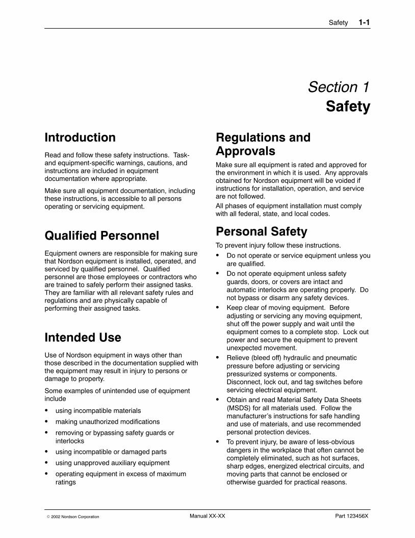
Introduction Read and follow these safety instructions. Task-and equipment-specific warnings, cautions, andinstructions are included in equipmentdocumentation where appropriate.
Make sure all equipment documentation, includingthese instructions, is accessible to all personsoperating or servicing equipment.
Qualified Personnel Equipment owners are responsible for making surethat Nordson equipment is installed, operated, andserviced by qualified personnel. Qualifiedpersonnel are those employees or contractors whoare trained to safely perform their assigned tasks.They are familiar with all relevant safety rules andregulations and are physically capable ofperforming their assigned tasks.
Intended Use Use of Nordson equipment in ways other thanthose described in the documentation supplied withthe equipment may result in injury to persons ordamage to property.
Some examples of unintended use of equipmentinclude
� using incompatible materials
� making unauthorized modifications
� removing or bypassing safety guards orinterlocks
� using incompatible or damaged parts
� using unapproved auxiliary equipment
� operating equipment in excess of maximumratings
Regulations andApprovals Make sure all equipment is rated and approved forthe environment in which it is used. Any approvalsobtained for Nordson equipment will be voided ifinstructions for installation, operation, and serviceare not followed.All phases of equipment installation must complywith all federal, state, and local codes.
Personal Safety To prevent injury follow these instructions.
� Do not operate or service equipment unless youare qualified.
� Do not operate equipment unless safetyguards, doors, or covers are intact andautomatic interlocks are operating properly. Donot bypass or disarm any safety devices.
� Keep clear of moving equipment. Beforeadjusting or servicing any moving equipment,shut off the power supply and wait until theequipment comes to a complete stop. Lock outpower and secure the equipment to preventunexpected movement.
� Relieve (bleed off) hydraulic and pneumaticpressure before adjusting or servicingpressurized systems or components.Disconnect, lock out, and tag switches beforeservicing electrical equipment.
� Obtain and read Material Safety Data Sheets(MSDS) for all materials used. Follow themanufacturer’s instructions for safe handlingand use of materials, and use recommendedpersonal protection devices.
� To prevent injury, be aware of less-obviousdangers in the workplace that often cannot becompletely eliminated, such as hot surfaces,sharp edges, energized electrical circuits, andmoving parts that cannot be enclosed orotherwise guarded for practical reasons.

Safety1-2
Part 123456X � 2002 Nordson CorporationManual XX-XX
Fire Safety To avoid a fire or explosion, follow theseinstructions.
� Do not smoke, weld, grind, or use open flameswhere flammable materials are being used orstored.
� Provide adequate ventilation to preventdangerous concentrations of volatile materialsor vapors. Refer to local codes or your materialMSDS for guidance.
� Do not disconnect live electrical circuits whileworking with flammable materials. Shut offpower at a disconnect switch first to preventsparking.
� Know where emergency stop buttons, shutoffvalves, and fire extinguishers are located. If afire starts in a spray booth, immediately shut offthe spray system and exhaust fans.
� Clean, maintain, test, and repair equipmentaccording to the instructions in your equipmentdocumentation.
� Use only replacement parts that are designedfor use with original equipment. Contact yourNordson representative for parts informationand advice.
Grounding
WARNING: Operating faulty electrostaticequipment is hazardous and can causeelectrocution, fire, or explosion. Makeresistance checks part of your periodicmaintenance program. If you receive evena slight electrical shock or notice staticsparking or arcing, shut down all electricalor electrostatic equipment immediately. Donot restart the equipment until the problemhas been identified and corrected.
All work conducted inside the spray booth or within1 m (3 ft) of booth openings is considered within aClass 2, Division 1 or 2 Hazardous location andmust comply with NFPA 33, NFPA 70 (NEC articles500, 502, and 516), and NFPA 77, latestconditions.
� All electrically conductive objects in the sprayareas shall be electrically connected to groundwith a resistance of not more than 1 megohmas measured with an instrument that applies atleast 500 volts to the circuit being evaluated.
� Equipment to be grounded includes, but is notlimited to, the floor of the spray area, operatorplatforms, hoppers, photoeye supports, andblow-off nozzles. Personnel working in thespray area must be grounded.
� There is a possible ignition potential from thecharged human body. Personnel standing on apainted surface, such as an operator platform,or wearing non-conductive shoes, are notgrounded. Personnel must wear shoes withconductive soles or use a ground strap tomaintain a connection to ground when workingwith or around electrostatic equipment.
� Operators must maintain skin-to-handle contactbetween their hand and the gun handle toprevent shocks while operating manualelectrostatic spray guns. If gloves must beworn, cut away the palm or fingers, wearelectrically conductive gloves, or wear agrounding strap connected to the gun handle orother true earth ground.
� Shut off electrostatic power supplies andground gun electrodes before makingadjustments or cleaning powder spray guns.
� Connect all disconnected equipment, groundcables, and wires after servicing equipment.
Action in the Event of aMalfunction If a system or any equipment in a systemmalfunctions, shut off the system immediately andperform the following steps:
� Disconnect and lock out electrical power. Closepneumatic shutoff valves and relieve pressures.
� Identify the reason for the malfunction andcorrect it before restarting the equipment.
Disposal Dispose of equipment and materials used inoperation and servicing according to local codes.
Description 2-1
Part 1030157A� 2002 Nordson Corporation
Section 2Description
IntroductionNOTE: Refer to the Vantage� RCM PowderCoating Booth Installation Guide for installationinstructions.
The Vantage Removable Color Module (RCM)powder coating booth provides complete powdercoating and powder recovery/reclaim.
Since powder coating systems are designed toeach customer’s requirements, each system has adifferent combination of equipment. This manualdescribes a basic, manually operated system. Yoursystem may have equipment not described in thismanual, such as automatic gun triggering and airmanagement systems. Before operating yoursystem, read the manuals for all equipment notcovered in this manual.
The Vantage RCM powder coating booth isavailable in three base lengths (9, 12, and 15 ft)and can be used with any powder applicationsystem.
The system can be permanently located under theconveyor, or mounted on casters and rails(roll-on/roll-off system). The roll-on/roll-off systemallows the booth to be moved off-line for colorchanges or maintenance.
Other options include a four-pump powder feedpump mounting plate, which allows fluidized,reclaimed powder in the color module hopper to bepumped directly to the spray guns; and a firedetection system, which must be installed in allspray booths with automatic spray guns.
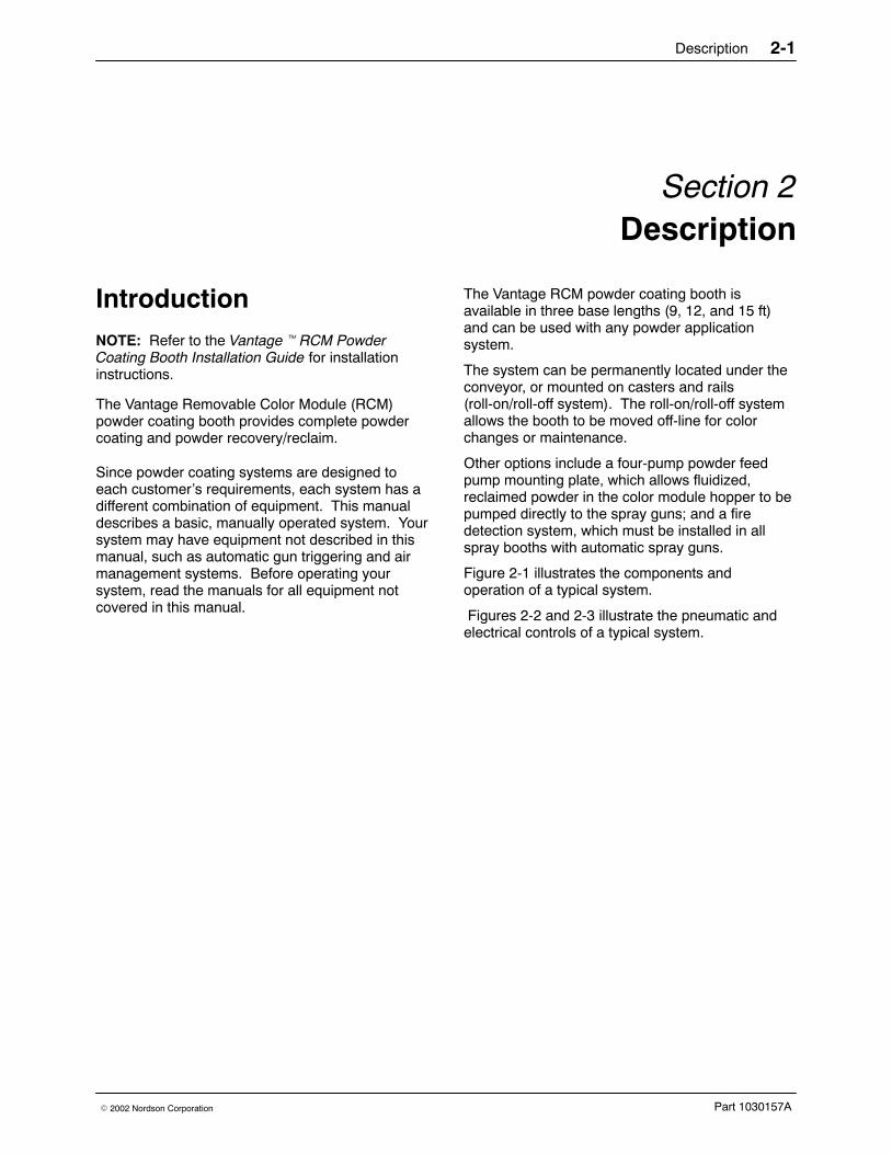
Figure 2-1 illustrates the components andoperation of a typical system.
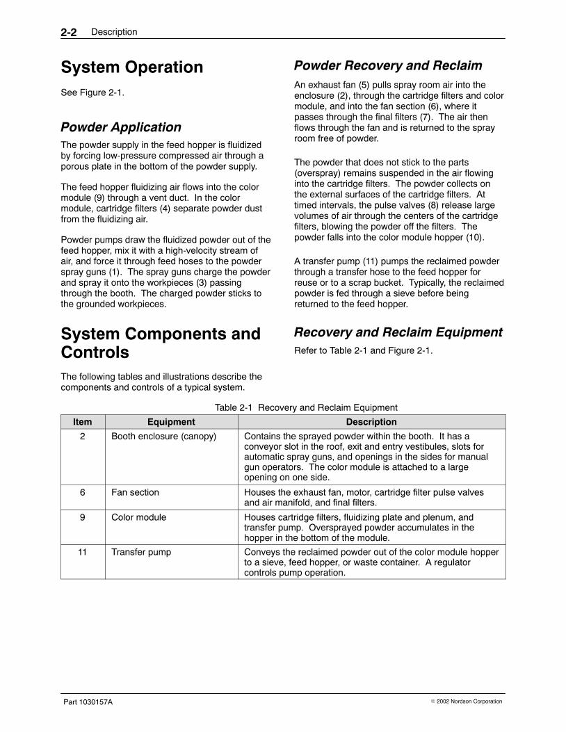
Figures 2-2 and 2-3 illustrate the pneumatic andelectrical controls of a typical system.
Description2-2
Part 1030157A � 2002 Nordson Corporation
System OperationSee Figure 2-1.
Powder ApplicationThe powder supply in the feed hopper is fluidizedby forcing low-pressure compressed air through aporous plate in the bottom of the powder supply.
The feed hopper fluidizing air flows into the colormodule (9) through a vent duct. In the colormodule, cartridge filters (4) separate powder dustfrom the fluidizing air.
Powder pumps draw the fluidized powder out of thefeed hopper, mix it with a high-velocity stream ofair, and force it through feed hoses to the powderspray guns (1). The spray guns charge the powderand spray it onto the workpieces (3) passingthrough the booth. The charged powder sticks tothe grounded workpieces.
Powder Recovery and Reclaim An exhaust fan (5) pulls spray room air into theenclosure (2), through the cartridge filters and colormodule, and into the fan section (6), where itpasses through the final filters (7). The air thenflows through the fan and is returned to the sprayroom free of powder.
The powder that does not stick to the parts(overspray) remains suspended in the air flowinginto the cartridge filters. The powder collects onthe external surfaces of the cartridge filters. Attimed intervals, the pulse valves (8) release largevolumes of air through the centers of the cartridgefilters, blowing the powder off the filters. Thepowder falls into the color module hopper (10).
A transfer pump (11) pumps the reclaimed powderthrough a transfer hose to the feed hopper forreuse or to a scrap bucket. Typically, the reclaimedpowder is fed through a sieve before beingreturned to the feed hopper.
System Components andControlsThe following tables and illustrations describe thecomponents and controls of a typical system.
Recovery and Reclaim EquipmentRefer to Table 2-1 and Figure 2-1.
Table 2-1 Recovery and Reclaim Equipment
Item Equipment Description
2 Booth enclosure (canopy) Contains the sprayed powder within the booth. It has aconveyor slot in the roof, exit and entry vestibules, slots forautomatic spray guns, and openings in the sides for manualgun operators. The color module is attached to a largeopening on one side.
6 Fan section Houses the exhaust fan, motor, cartridge filter pulse valvesand air manifold, and final filters.
9 Color module Houses cartridge filters, fluidizing plate and plenum, andtransfer pump. Oversprayed powder accumulates in thehopper in the bottom of the module.
11 Transfer pump Conveys the reclaimed powder out of the color module hopperto a sieve, feed hopper, or waste container. A regulatorcontrols pump operation.
Description 2-3
Part 1030157A� 2002 Nordson Corporation
1400810A
Air Flow
Powder Flow
1
32
9
5
6
4
78
11
10
12
13
Figure 2-1 System Components and Operation
1. Powder spray gun2. Enclosure3. Workpiece4. Cartridge filters5. Exhaust fan
6. Fan section7. Final filters8. Pulse valves9. Color module
10. Color module hopper
11. Transfer pump12. Powder feed pump mounting
plate (optional)13. Vent plate for 3.5 or 5 inch vent
hose

Description2-4
Part 1030157A � 2002 Nordson Corporation
System ControlsRefer to Table 2-2 and Figure 2-2.
Table 2-2 System Controls
Item Equipment Description
1 Electrical panel Houses motor starters and overload protectors, fuses, relays,switches, basic system controls and indicator lights, and thepulse valve timer board. Refer to System Electrical Panel formore information.
2 Flame detectorindicator/relay panel(optional)
Provides visible and audible fault and fire alarms and interlockrelays. If a detector senses a flame the interlock relays shutdown the conveyor, booth exhaust fan, compressed air, andelectrical power to the spray guns. ANSI/NFPA-33 standardsrequire flame detectors in all systems equipped with automaticspray guns.
3 Pneumatic manifold Includes air-pressure regulators and gauges for cartridgepulsing, color module hopper fluidizing, transfer pumpoperation, and other pneumatic equipment.
4 Pulse air solenoids Open and close the pulse valves on signals from the pulsevalve timer in the electrical panel.
5 Pulse air controls Regulate the pulse air pressure and volume. Controls includea regulator, pressure gauge, and gate valve.
6 Flame detectors (optional) Monitor the enclosure interior for flames. The detectors useIR sensing technology and include a through-the-lens self testto check for lens blockage.
7 Fluidizing air controls Regulate fluidizing air pressure to the color module hopper.
Description 2-5
Part 1030157A� 2002 Nordson Corporation
1400811A
1
6
4
8
0 5
0 10
3
5
7
2
Figure 2-2 System Controls
1. Electrical panel2. Flame detector indicator/relay
panel (optional)3. Pneumatic manifold
4. Pulse air solenoids5. Pulse air control6. Color module fluidizing
air control
7. Transfer pump air control8. Flame detector (optional)

Description2-6
Part 1030157A � 2002 Nordson Corporation
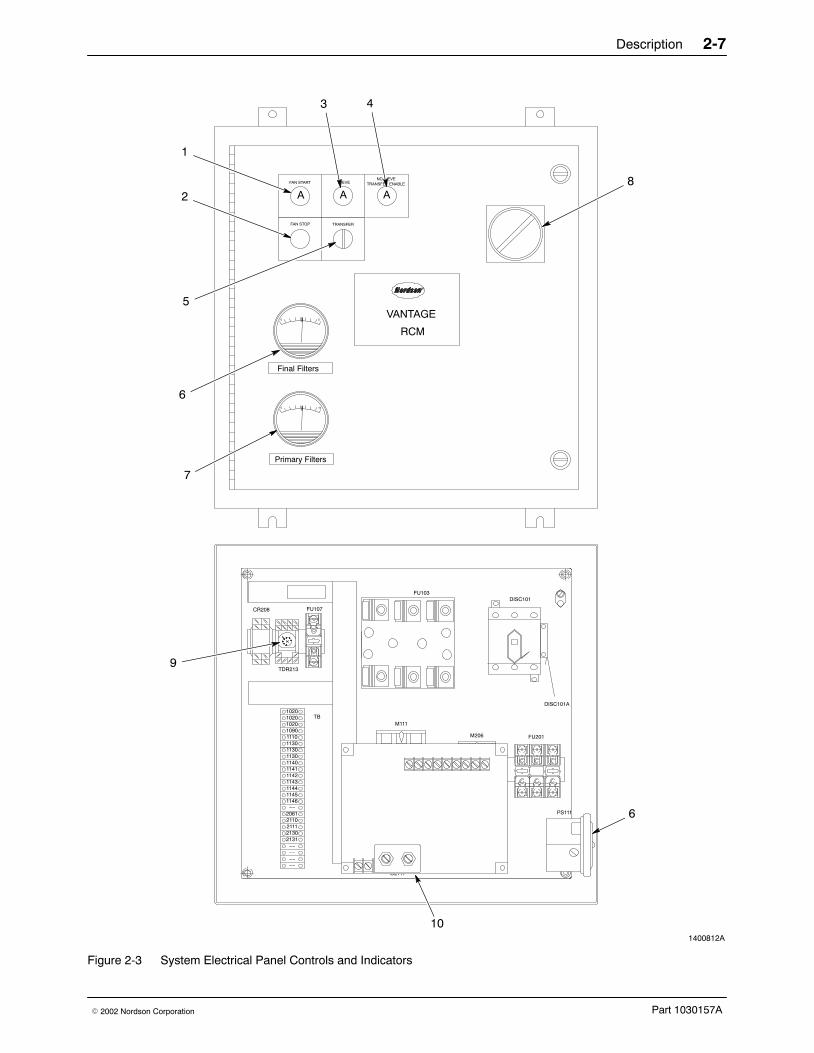
System Electrical PanelRefer to Table 2-3 and Figure 2-3.
Your system’s electrical panel may be different.Refer to Troubleshooting for electrical schematics.
Table 2-3 System Electrical Panel
Item Component Function
1 FAN STARTpushbutton/indicator
Starts the exhaust fan and indicates that the fan is on (amberlight).
2 FAN STOP pushbutton Stops the exhaust fan.
3 SIEVE indicator Indicates that the sieve is on (amber light). Included withsieve option.
4 NO SIEVE TRANSFERENABLEpushbutton/indicator
Allows the transfer pump to be turned on (in either Manual orAuto mode) if the sieve is disconnected (amber light).Included with sieve option.
5 TRANSFER switch Three-position switch (Manual, Off, Auto). Controls operationof the transfer pump. In Auto mode, the transfer pump isturned on by a signal from the feed hopper level sensor, afterthe delay on timer runs out. Included with transfer option.
6 FINAL FILTER differentialpressure gauge and switch
Senses and indicates the pressure drop across the final filters.At 3-in. wc, the final filter pressure switch opens andautomatically shuts down the system.
7 PRIMARY (cartridge) FILTERdifferential pressure gauge
Senses and indicates the pressure drop across the cartridgefilters.
8 Disconnect switch Turns on and off power to panel and system.
9 Transfer pump delay on timer Sets transfer pump delay on time. Provides a delay after thefeed hopper level sensor signals for powder before starting thetransfer pump. Prevents constant cycling of transfer pump.Included with transfer option.
10 Pulse valve timer board(mounted on inside of door)
Controls cartridge filter pulse frequency and duration. Off(frequency) time sets time between pulses, on (duration) timesets valve open time.
Description 2-7
Part 1030157A� 2002 Nordson Corporation
1400812A
Primary Filters
Final Filters
TRANSFER
PS111
FU201M206
OL206
0 5
0 10
SIEVE
R
VANTAGE
RCM
M111
OL111
FU103DISC101
DISC101A
TB
TDR213
FAN STOP
FAN START
A
FU107
NO SIEVETRANSFER ENABLE
CR208
102010201020
113011101090
11431142
1130
11401141
1130
11451144
1146−−
2061
−−
2110211121302131
−−−−−−
A A
1
2
3 4
6
7
8
6
10
9
5
Figure 2-3 System Electrical Panel Controls and Indicators
Description2-8
Part 1030157A � 2002 Nordson Corporation
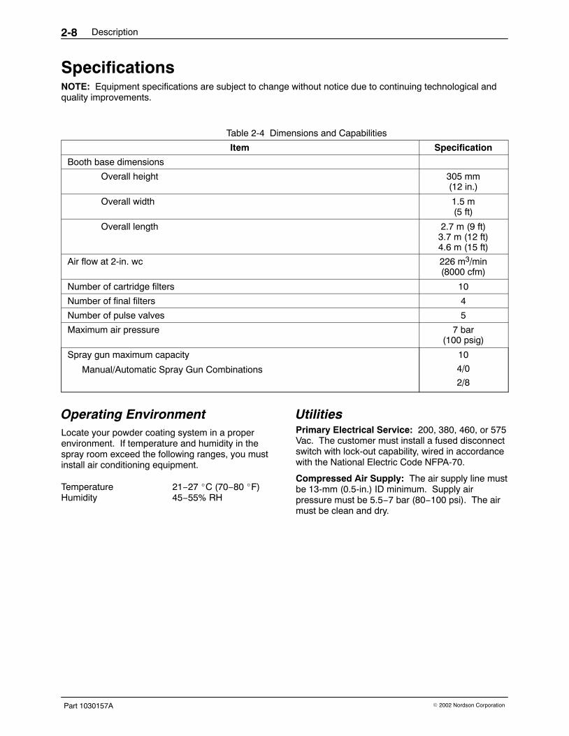
SpecificationsNOTE: Equipment specifications are subject to change without notice due to continuing technological andquality improvements.
Table 2-4 Dimensions and Capabilities
Item Specification
Booth base dimensions
Overall height 305 mm(12 in.)
Overall width 1.5 m(5 ft)
Overall length 2.7 m (9 ft)3.7 m (12 ft)4.6 m (15 ft)
Air flow at 2-in. wc 226 m3/min(8000 cfm)
Number of cartridge filters 10
Number of final filters 4
Number of pulse valves 5
Maximum air pressure 7 bar(100 psig)
Spray gun maximum capacity
Manual/Automatic Spray Gun Combinations
10
4/0
2/8
Operating EnvironmentLocate your powder coating system in a properenvironment. If temperature and humidity in thespray room exceed the following ranges, you mustinstall air conditioning equipment.
Temperature 21−27 �C (70−80 �F)Humidity 45−55% RH
UtilitiesPrimary Electrical Service: 200, 380, 460, or 575Vac. The customer must install a fused disconnectswitch with lock-out capability, wired in accordancewith the National Electric Code NFPA-70.
Compressed Air Supply: The air supply line mustbe 13-mm (0.5-in.) ID minimum. Supply airpressure must be 5.5−7 bar (80−100 psi). The airmust be clean and dry.

Description 2-9
Part 1030157A� 2002 Nordson Corporation
Normal Design StandardsSpray booths are custom-designed to eachcustomer’s requirements, so some booths maydeviate from these design standards. Contact yourNordson representative if you need moreinformation about the design of your booth.
End Openings: 91 x 152 cm (3 x 5 ft)Part Hanger Keyhole Slot: 30.5 cm (12 in.) highCross Drafts: No more than 18.3 m/min (60 FPM)Average Face Velocity: No less than 30.5 m/min(100 FPM) through all openings in the boothenclosureTemperature of Parts Entering Booth: No morethan 49 �C (120 �F)
Powder: Use commercially available powdercoatings. Note that the characteristics andproperties of a powder coating can affect systemoperation.
Powder coatings generally have an averageparticle size of 25−35 microns, with no more than10% of the total being less than 15 microns. Whenthe percentage of particles less than 15 micronsexceeds 10% of the total, the filter media can clog.
Cartridge Filters: Cartridge filters are consideredwear items. The variables affecting the lifeexpectancy of a cartridge filter include
� type of coating material
� particle size distribution
� humidity and temperature of the spray room air
� hours of operation
� dew point and cleanliness of the compressedair supply
� pressure and frequency of air pulses used toclean the filters
Compressed Air Supply: The air must beconditioned by a dedicated, refrigerated orregenerative-desiccant air dryer that can produce a3 �C (38 �F) or lower dewpoint at 7 bar (100 psi).

Description2-10
Part 1030157A � 2002 Nordson Corporation

Operation 3-1
Part 1030157A� 2002 Nordson Corporation
Section 3Operation
WARNING: Allow only qualified personnelto perform the following tasks. Follow thesafety instructions in this document and allother related documentation.
New System StartupUse these procedures to prepare your powdercoating booth for production operation.
Your Nordson Corporation representative will helpyou set up your application equipment and adjustyour system control settings before you startpowder coating your products. Record the systemsettings on the charts provided at the end of thissection. Make extra copies of the charts asneeded.
NOTE: Since powder coating systems arecustom-designed to each customer’s requirements,each system has a different combination ofequipment. Your system may have equipment notdescribed in this manual.
System Settings
WARNING: Even with the electrical paneldisconnect in the off position, the inputterminals at the top of the switch are stilllive. Do not touch them. Failure toobserve this warning could result in seriousinjury or death.
See Figure 3-1.
1. Disconnect and lock out the system electricalpower and open the booth electrical panel door.
2. The timer board (10) is mounted on the insideof the door. Set the pulse valve OFF timer to15 seconds and the ON timer to 110milliseconds.
3. Close the electrical panel door.
4. Turn on the compressed air supply. Adjust thesystem air pressure to 5.5 bar (80 psi).
5. Turn on the disconnect switch (8).
6. Turn on the exhaust fan by pressing the FANSTART (1) button. If your booth is equippedwith the sieve option, the sieve will start.
7. Adjust the pulse-valve air pressure and volume.
a. Set the pulse valve regulator to 4.1−5.2 bar(60−75 psi). Watch the pressure gauge; thepressure will drop when the valves open.
b. Adjust the gate valve so the air pressurereturns to 4.1−5.2 bar (60−75 psi) justbefore the next pulse. This will prevent thevalves from being deprived of air duringpulses.
Transfer Option Settings Transfer Pump Operation
If you want the transfer pump to start automaticallywhen the feed hopper level sensor signals forpowder, turn the TRANSFER switch (5) to Auto.
If your booth is equipped with the sieve option, andyou disconnect the sieve from the system, youmust press the NO SIEVE TRANSFER ENABLEpushbutton (4) to operate the transfer pump ineither Manual or Auto mode.
Delay-On Timer
The transfer pump delay-on timer range is 0−180seconds. The default setting is 60 seconds. Toprevent constant transfer pump cycling, do notmake the delay shorter. Adjust the timer for alonger delay if desired.

Operation3-2
Part 1030157A � 2002 Nordson Corporation
Transfer Option Settings (contd)
1400813A
Primary Filters
Final Filters
TRANSFER
0 5
0 10
SIEVE
TB
TDR213
FAN STOP
FAN START
A
FU107
NO SIEVETRANSFER ENABLE
CR208
102010201020
113011101090
11431142
1130
11401141
1130
11451144
1146−−
2061
−−
2110211121302131
−−−−−−
A A
1
2
3 4
6
7
8
9
5
Internal View
Panel Front
10
Figure 3-1 System Controls and Timers
1. FAN START pushbutton/indicator2. FAN STOP pushbutton3. SIEVE indicator4. NO SIEVE TRANSFER ENABLE
pushbutton
5. TRANSFER switch(manual/off/auto)
6. Final filter pressure gauge7. Primary (cartridge) filter pressure
gauge
8. Disconnect switch9. Transfer pump delay-on timer
10. Pulse valve timer board
Note: Pulse valve timer board (10) is mounted on inside of door.

Operation 3-3
Part 1030157A� 2002 Nordson Corporation
Daily Startup andShutdown ProceduresUse these procedures for routine operation of yoursystem.
WARNING: Wear an approved respiratorand safety glasses or goggles whenhandling powder, operating sprayequipment, or performing maintenance orcleaning operations. Obtain and readMaterial Safety Data Sheets for eachpowder used.
Startup1. Turn on the system electrical power and
compressed air supply.
2. Turn on the exhaust fan. If your booth isequipped with the sieve option, the sieve willalso start.
3. Check the level of the powder in the feedhopper. Fill feed hoppers no more than 2/3 fullto leave room for expansion when fluidizing airis turned on.
4. Turn on the feed hopper fluidizing air.
5. Walk around the booth. Make sure theapplication equipment power and air is on.Make sure the transfer and feed hoses aresecurely connected at both ends.
6. Check all equipment ground connections.
7. Make sure the flame detector system, if used, isfunctioning correctly.
8. Turn on the automatic-gun master control unitand the manual-gun control units.
9. Adjust the kV settings and the powder feedpump air pressures, if necessary. Refer to yourspray gun and control unit manuals.
10. Start the conveyor and start sprayingworkpieces.
11. Measure the air flow velocity at the vestibuleswith a velometer. The velocity should be30.5−36.6 m/min (100−120 ft/min). Make surethe sprayed powder is not being pulled awayfrom the workpieces, and that the powder is notescaping from the enclosure openings.
Shutdown1. Turn on the color module fluidizing air. Start the
transfer pump and pump the reclaimed powderfrom the color module hopper to the feedhopper.
2. Turn off the automatic-gun master control unitand the manual-gun control units.
3. Perform the daily maintenance proceduresdescribed in Maintenance. Clean the powderpumps and spray guns as described in theirmanuals. Perform daily maintenanceprocedures for other system equipment, asdescribed in their manuals.
4. Turn off the exhaust fan. Shut off the systemelectrical power and compressed air supply.

Operation3-4
Part 1030157A � 2002 Nordson Corporation
Color ChangeSee Figure 3-2.
1. Clean the spray guns and feed hoses asdescribed in the spray gun manuals.
2. Clean the enclosure as described in the DailyMaintenance procedures in Maintenance.
3. Shut off the system electrical power andcompressed air supply. Relieve the system airpressure.
4. Disconnect the powder hose and air tubing fromthe transfer pump (4).
5. Disconnect the fluidizing air tubing (6) from thecolor module hopper plenum.
6. Release the clamps (3, 5) securing the colormodule (2) to the fan section (1) and enclosure.
7. Roll the color module away from the booth.Install the storage cover on the color moduleand move it to a storage area.
1400814A
1
4 35
2
6
Figure 3-2 Removing the Color Module
1. Fan section2. Color module
3. Clamps4. Transfer pump
5. Clamps6. Fluidizing air tubing
See Figure 3-3.
8. Thoroughly clean any powder off the inletframe (2) and the mating surface of the fansection.
9. Inspect the final filters. If there is a largeamount of powder on the final filters, a cartridgefilter in the color module you just removed maybe leaking. Refer to Troubleshooting andRepair for instructions.
10. Remove the storage cover from the new colormodule (3). Inspect the gaskets (4, 6).Replace them if they are damaged.
11. Position the new color module against the fansection and the inlet frame.
12. Level the color module and adjust its height, ifnecessary, with the four leveling screws (5).

Operation 3-5
Part 1030157A� 2002 Nordson Corporation
13. See Figure 3-2. Hook the clamps (3) to theenclosure. Engage the clamps to pull the colormodule against the stops and compress thegasket (6) against the inlet frame.
14. Hook the clamps (5) to the fan section (1) andengage them to compress the gasket (4)against the fan section.
15. Connect the air tubing and powder hose to thetransfer pump (4) and the fluidizing airtubing (6) to the hopper plenum.
16. Turn on the system electrical power andcompressed air supply.
17. Start the exhaust fan.
18. Change the powder supply and resumeproduction.
1400815A
3
5
6
2
1
4
Figure 3-3 Installing a New Color Module
1. Fan section2. Inlet frame
3. New color module4. Gasket
5. Leveling screws6. Gasket

Operation3-6
Part 1030157A � 2002 Nordson Corporation
System Settings
EquipmentRecommendedInitial Settings Final Setting Changes
Primary Air Pressure (plant supply) 5.5 bar (80 psi)
Collector Module
#1 Fluidizing 0.7 bar (10 psi)
#1 Transfer pump 1.7 bar (25 psi)
Feed Hopper — Reclaim
Fluidizing 0.5 bar (8 psi)
Vent-assist 0.5 bar (8 psi)
Feed Hopper — Non-Reclaim
#1 Fluidizing 0.5 bar (8 psi)
#2 Fluidizing 0.5 bar (8 psi)
#3 Fluidizing 0.5 bar (8 psi)
Vent-assist 0.5 bar (8 psi)
Pulse Manifold
Air pressure 4.1−5.2 bar(60−75 psi)
NFS-1000 Fire Detector
Air pressure 0.7 bar (10 psi)(preset)
Vibratory Sieve
Air pressure 3.5 bar (50 psi)
Pulse Timer
Delay (OFF) time 15.0 sec
Duration (ON) time 110 msec
Filter Pressure Drop Maximum Readings
Cartridge filters 1−3 in. wc
Final filters 2 in. wc

Operation 3-7
Part 1030157A� 2002 Nordson Corporation
EquipmentRecommendedInitial Settings Final Setting Changes
Automatic Spray Guns
#1 Flow-rate 2.1 bar (30 psi)
Atomizing 1.4 bar (20 psi)
Voltage 90−100 kV
AFC 40 A
#2 Flow-rate 2.1 bar (30 psi)
Atomizing 1.4 bar (20 psi)
Voltage 90−100 kV
AFC 40 A
#3 Flow-rate 2.1 bar (30 psi)
Atomizing 1.4 bar (20 psi)
Voltage 90−100 kV
AFC 40 A
#4 Flow-rate 2.1 bar (30 psi)
Atomizing 1.4 bar (20 psi)
Voltage 90−100 kV
AFC 40 A
#5 Flow-rate 2.1 bar (30 psi)
Atomizing 1.4 bar (20 psi)
Voltage 90−100 kV
AFC 40 A
#6 Flow-rate 2.1 bar (30 psi)
Atomizing 1.4 bar (20 psi)
Voltage 90−100 kV
AFC 40 A
#7 Flow-rate 2.1 bar (30 psi)
Atomizing 1.4 bar (20 psi)
Voltage 90−100 kV
AFC 40 A
#8 Flow-rate 2.1 bar (30 psi)
Atomizing 1.4 bar (20 psi)
Voltage 90−100 kV
AFC 40 A

Operation3-8
Part 1030157A � 2002 Nordson Corporation
Maintenance 4-1
Part 1030157A� 2002 Nordson Corporation
Section 4Maintenance
WARNING: Allow only qualified personnelto perform the following tasks. Follow thesafety instructions in this document and allother related documentation.
Daily MaintenancePerform these procedures daily to keep yoursystem clean and functioning properly.
WARNING: Wear an approved respiratorand safety glasses or goggles whenhandling powder, operating sprayequipment, or performing maintenance orcleaning operations. Obtain and readMaterial Safety Data Sheets for eachpowder used.
CleaningPerform this procedure daily and when changingpowder color or type.
1. Turn off the spray gun control units.
2. Turn on the exhaust fan.
3. Disconnect the powder-feed hoses from thepowder pumps. Blow the powder out of thehoses and spray guns with compressed air.
4. Ground the gun electrodes, if applicable, andclean the spray guns according to theinstructions in their manuals.
5. Clean the enclosure roof, walls, and floor with arubber squeegee. Push the collected powderinto the color module.
6. Remove the remaining powder residue from theenclosure with an air-powered vacuum and asoft brush attachment. Wipe down all surfaceswith a damp, lint-free cloth (do not use tackcloths). If you remove the color module, cleanthe inlet frame and fan section mating surfaces.
7. Turn off the exhaust fan by pressing the FANSTOP button on the electrical panel.
8. Clean the operator’s platform and the flooraround the booth.
Maintenance4-2
Part 1030157A � 2002 Nordson Corporation
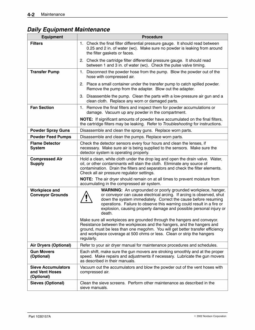
Daily Equipment MaintenanceEquipment Procedure
Filters 1. Check the final filter differential pressure gauge. It should read between0.25 and 2 in. of water (wc). Make sure no powder is leaking from aroundthe filter gaskets or faces.
2. Check the cartridge filter differential pressure gauge. It should readbetween 1 and 3 in. of water (wc). Check the pulse valve timing.
Transfer Pump 1. Disconnect the powder hose from the pump. Blow the powder out of thehose with compressed air.
2. Place a small container under the transfer pump to catch spilled powder.Remove the pump from the adapter. Blow out the adapter.
3. Disassemble the pump. Clean the parts with a low-pressure air gun and aclean cloth. Replace any worn or damaged parts.
Fan Section 1. Remove the final filters and inspect them for powder accumulations ordamage. Vacuum up any powder in the compartment.
NOTE: If significant amounts of powder have accumulated on the final filters,the cartridge filters may be leaking. Refer to Troubleshooting for instructions.
Powder Spray Guns Disassemble and clean the spray guns. Replace worn parts.
Powder Feed Pumps Disassemble and clean the pumps. Replace worn parts.
Flame DetectorSystem
Check the detector sensors every four hours and clean the lenses, ifnecessary. Make sure air is being supplied to the sensors. Make sure thedetector system is operating properly.
Compressed AirSupply
Hold a clean, white cloth under the drop leg and open the drain valve. Water,oil, or other contaminants will stain the cloth. Eliminate any source ofcontamination. Drain the filters and separators and check the filter elements.Check all air pressure regulator settings.
NOTE: The air dryer should remain on at all times to prevent moisture fromaccumulating in the compressed air system.
Workpiece andConveyor Grounds
WARNING: An ungrounded or poorly grounded workpiece, hanger,or conveyor can cause electrical arcing. If arcing is observed, shutdown the system immediately. Correct the cause before resumingoperations. Failure to observe this warning could result in a fire orexplosion, causing property damage and possible personal injury ordeath.
Make sure all workpieces are grounded through the hangers and conveyor.Resistance between the workpieces and the hangers, and the hangers andground, must be less than one megohm. You will get better transfer efficiencyand workpiece coverage at 500 ohms or less. Clean or strip the hangersregularly.
Air Dryers (Optional) Refer to your air dryer manual for maintenance procedures and schedules.
Gun Movers(Optional)
Each shift, make sure the gun movers are stroking smoothly and at the properspeed. Make repairs and adjustments if necessary. Lubricate the gun moversas described in their manuals.
Sieve Accumulatorsand Vent Hoses(Optional)
Vacuum out the accumulators and blow the powder out of the vent hoses withcompressed air.
Sieves (Optional) Clean the sieve screens. Perform other maintenance as described in thesieve manuals.

Maintenance 4-3
Part 1030157A� 2002 Nordson Corporation
Weekly MaintenanceEquipment Procedure
Powder Spray Gunsand Cables
Clean the spray guns. Perform electrostatic resistance checks as described inthe spray gun manuals.
Powder Feed Pumpsand Feed Hoses
Disassemble the pumps and clean them. Replace any worn or damagedparts. Blow out the feed hoses with compressed air, from the pump end intothe booth. Replace damaged hoses.
Powder Feed Source(feed hopper, boxfeeder, etc.)
Remove the powder from the source. If using a feed hopper, vacuum theinterior and check the fluidizing plate. If the plate is stained, the air supplycould be contaminated by oil or moisture. Check the air dryer and air filters.Replace the fluidizing plate if it is contaminated.
Color Module Start the exhaust fan and pulse the cartridge filters to blow off as much powderas possible. Pump the powder out of the color module.
Disconnect the powder hose from the transfer pump. Blow the powder out ofthe hose with compressed air. Remove the transfer pump and clean it.
Vacuum the color module fluidizing plate and check it. If the fluidizing plate isstained, the air supply could be contaminated by oil or moisture. Check the airdryer and air filters. Replace the fluidizing plate if it is contaminated.
Check the gaskets and replace any that are cracked or damaged.
Booth Enclosure Turn on the exhaust fan and vacuum the enclosure roof, walls, and floor with asoft brush attachment. Wipe down the enclosure with damp, lint-free cloths.Clean the booth exterior, all attached equipment, and the spray room.
Periodic MaintenanceEquipment Procedure
ElectricalConnections
Check all terminal blocks and junction boxes for loose wires. Tighten anyloose connections and inspect all wiring for damaged insulation. Replace thewiring if the insulation is damaged.
Spray Guns andCables
Perform electrostatic resistance checks as described in the spray gun andspray gun control unit manuals.
Air Dryer Check the air dryer operation. Refer to your air dryer manual for maintenanceprocedures and schedules.
Gaskets Inspect all gaskets and seals for damage. Replace any that are damaged.
Fan Motor Bearings Every six months, lubricate the motor bearings with two shots of lithium orpolyurea grease from a grease gun. The grease fittings are on the motorhousing.
Differential PressureGauges
Observe and record the differential pressure gauge readings. Readingsgreater than the following mean that the filters are clogged and must bereplaced. Correct the cause of the clogging before resuming operations.
Primary Filter: 1−3 in. wc
Final Filters: 0.25−2 in. wc
Powder Feed Hoses Disconnect the powder feed hoses from the powder pumps. Blow the powderout of the hoses with compressed air. Never blow air through the hosestoward the pumps. Replace the hoses if they are clogged with impact-fusedpowder.
Casters Lubricate the color module and roll-on/roll-off casters with a lithium grease.

Maintenance4-4
Part 1030157A � 2002 Nordson Corporation
Maintenance Check List
ActivityEachShift Daily Weekly Monthly
ColorChange
Cleaning
Accumulator �
Booth enclosure � � �
Color module � �
Fan and pulse-valve compartments � �
Feed hoses and transfer hoses � �
Fire detector head lenses* � �
Spray gun pumps � � � �
Spray guns � � �
Transfer pump � � �
Vent hoses � �
Sieve � �
Resistance Checks—Guns and Cables �
Visual Checks
Air supply drop leg �
Air dryer �
Cartridge filter differential-pressuregauge
�
Final filter differential-pressure gauge �
Electrical connections �
Fire detector sensors � �
Gaskets �
Gun movers �
Workpiece clearance** �
Workpiece grounding � �
Powder levels �
Lubrication
Motor bearings***
Casters (color module androll-on/roll-off)***
�
* Every 4 hours.
** Clearances should be monitored continuously.
*** Every 6 months.
Troubleshooting 5-1
Part 1030157A� 2002 Nordson Corporation
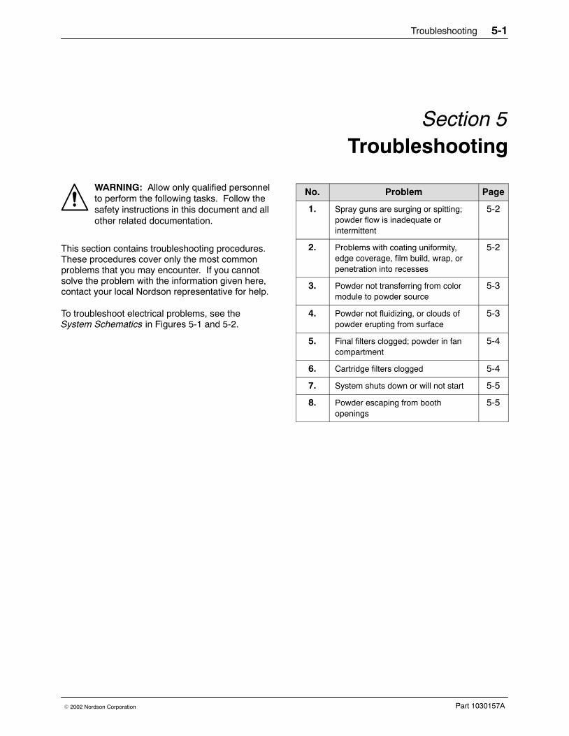
Section 5Troubleshooting
WARNING: Allow only qualified personnelto perform the following tasks. Follow thesafety instructions in this document and allother related documentation.
This section contains troubleshooting procedures.These procedures cover only the most commonproblems that you may encounter. If you cannotsolve the problem with the information given here,contact your local Nordson representative for help.
To troubleshoot electrical problems, see theSystem Schematics in Figures 5-1 and 5-2.
No. Problem Page
1. Spray guns are surging or spitting;powder flow is inadequate orintermittent
5-2
2. Problems with coating uniformity,edge coverage, film build, wrap, orpenetration into recesses
5-2
3. Powder not transferring from colormodule to powder source
5-3
4. Powder not fluidizing, or clouds ofpowder erupting from surface
5-3
5. Final filters clogged; powder in fancompartment
5-4
6. Cartridge filters clogged 5-4
7. System shuts down or will not start 5-5
8. Powder escaping from boothopenings
5-5

Troubleshooting5-2
Part 1030157A � 2002 Nordson Corporation
TroubleshootingProcedures
Problem Possible Cause Corrective Action
1. Spray guns are surgingor spitting; powderflow is inadequate orintermittent
Powder in feed hopperinadequately fluidized
Adjust the fluidizing air pressure.The powder should be gently boiling.Refer to problem 4.
Low powder level in feed hopper Add powder to the feed hopper.Refer to problem 3.
Powder pump venturi nozzles orthroats worn; adapter O-ringsleaking; pump or pickup tubeclogged
Clean the pump and pickup tube.Replace any worn parts. Replace theadapter O-rings if they are damaged.
Obstruction in powder-feed hose Disconnect the feed hose from thepump. Blow the powder out of thehose with compressed air. Makesure the hose is clear. Eliminatekinks or severe bends in the hose.The hose should be no longer than7.6 m (25 ft) with a maximum 2.7-m(9-ft) vertical rise.
Severe tribo-charging in powderfeed hose
Contact your Nordson Corporationrepresentative for a suitable hosematerial. Contact your powdersupplier.
Obstruction in spray gun Clean the spray gun. If you are usingconical nozzles, make sure there is a3-mm (0.125-in.) or larger gapbetween the deflector and the nozzle.
Flow-rate or atomizing air pressureincorrect
Refer to the spray gun and controlunit manuals for recommended airpressures and ratios.
2. Problems withcoating uniformity,edge coverage, filmbuild, wrap, orpenetration intorecesses
Poor workpiece grounding Resistance from workpiece to groundmust be less than one megohm. Forbest results, resistance should not bemore than 500 ohms. Clean theworkpiece hangers, fixtures, andhooks if necessary. Check theconveyor ground.
Spray gun placement incorrect Position the spray guns25.4−35.6 cm (10−14 in.) from theworkpieces. Stagger the spray guns30.5 cm (12 in.) apart vertically and53.3 cm (21 in.) apart horizontally toavoid fan pattern and electrostaticfield overlap. Contact your NordsonCorporation representative.
Flow-rate and atomizing airpressure incorrect
Refer to the spray gun and controlunit manuals for the recommendedair pressures and ratios.
Continued...
Troubleshooting 5-3
Part 1030157A� 2002 Nordson Corporation
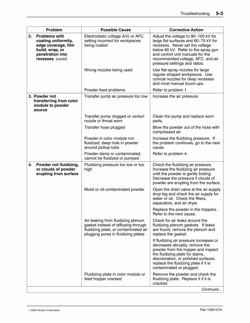
Problem Possible Cause Corrective Action
2. Problems withcoating uniformity,edge coverage, filmbuild, wrap, orpenetration intorecesses (contd)
Electrostatic voltage (kV) or AFCsetting incorrect for workpiecesbeing coated
Adjust the voltage to 90−100 kV forlarge flat surfaces and 60−75 kV forrecesses. Never set the voltagebelow 60 kV. Refer to the spray gunand control unit manuals for therecommended voltage, AFC, and airpressure settings and ratios.
Wrong nozzles being used Use flat-spray nozzles for largeregular-shaped workpieces. Useconical nozzles for deep recessesand most manual touch-ups.
Powder feed problems Refer to problem 1.
3. Powder nottransferring from colormodule to powdersource
Transfer pump air pressure too low Increase the air pressure.
Transfer pump clogged or venturinozzle or throat worn
Clean the pump and replace wornparts.
Transfer hose plugged Blow the powder out of the hose withcompressed air.
Powder in color module notfluidized; deep hole in powderaround pickup tube
Increase the fluidizing pressure. Ifthe problem continues, go to the nextcause.
Powder damp or contaminated;cannot be fluidized or pumped
Refer to problem 4.
4. Powder not fluidizing,or clouds of powdererupting from surface
Fluidizing pressure too low or toohigh
Check the fluidizing air pressure.Increase the fluidizing air pressureuntil the powder is gently boiling.Decrease the pressure if clouds ofpowder are erupting from the surface.
Moist or oil-contaminated powder Open the drain valve at the air-supplydrop leg and check the air supply forwater or oil. Check the filters,separators, and air dryer.
Replace the powder in the hoppers.Refer to the next cause.
Air leaking from fluidizing plenumgasket instead of diffusing throughfluidizing plate, or contaminated airplugging pores in fluidizing plates
Check for air leaks around thefluidizing plenum gaskets. If leaksare found, remove the plenum andreplace the gasket.
If fluidizing air pressure increases ordecreases abruptly, remove thepowder from the hopper and inspectthe fluidizing plate for stains,discoloration, or polished surfaces.replace the fluidizing plate if it iscontaminated or plugged.
Fluidizing plate in color module orfeed hopper cracked
Remove the powder and check thefluidizing plate. Replace it if it iscracked.
Continued...
Troubleshooting5-4
Part 1030157A � 2002 Nordson Corporation
Troubleshooting Procedures (contd)
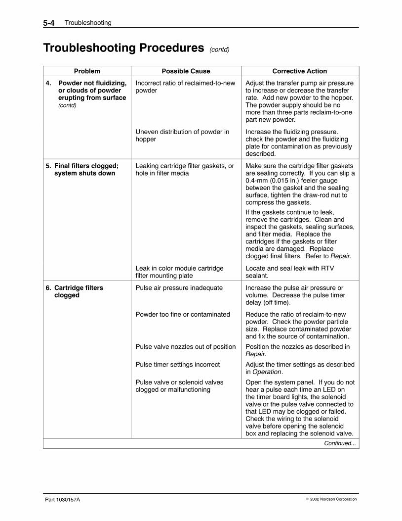
Problem Possible Cause Corrective Action
4. Powder not fluidizing,or clouds of powdererupting from surface (contd)
Incorrect ratio of reclaimed-to-newpowder
Adjust the transfer pump air pressureto increase or decrease the transferrate. Add new powder to the hopper.The powder supply should be nomore than three parts reclaim-to-onepart new powder.
Uneven distribution of powder inhopper
Increase the fluidizing pressure.check the powder and the fluidizingplate for contamination as previouslydescribed.
5. Final filters clogged;system shuts down
Leaking cartridge filter gaskets, orhole in filter media
Make sure the cartridge filter gasketsare sealing correctly. If you can slip a0.4-mm (0.015 in.) feeler gaugebetween the gasket and the sealingsurface, tighten the draw-rod nut tocompress the gaskets.
If the gaskets continue to leak,remove the cartridges. Clean andinspect the gaskets, sealing surfaces,and filter media. Replace thecartridges if the gaskets or filtermedia are damaged. Replaceclogged final filters. Refer to Repair.
Leak in color module cartridgefilter mounting plate
Locate and seal leak with RTVsealant.
6. Cartridge filtersclogged
Pulse air pressure inadequate Increase the pulse air pressure orvolume. Decrease the pulse timerdelay (off time).
Powder too fine or contaminated Reduce the ratio of reclaim-to-newpowder. Check the powder particlesize. Replace contaminated powderand fix the source of contamination.
Pulse valve nozzles out of position Position the nozzles as described inRepair.
Pulse timer settings incorrect Adjust the timer settings as describedin Operation.
Pulse valve or solenoid valvesclogged or malfunctioning
Open the system panel. If you do nothear a pulse each time an LED onthe timer board lights, the solenoidvalve or the pulse valve connected tothat LED may be clogged or failed.Check the wiring to the solenoidvalve before opening the solenoidbox and replacing the solenoid valve.
Continued...

Troubleshooting 5-5
Part 1030157A� 2002 Nordson Corporation
Problem Possible Cause Corrective Action
7. System shuts down orwill not start
Flame detector system sees aflame or spark, or is malfunctioning
Check the inside of the enclosureand color module, the detector headaim, and the workpiece and conveyorgrounds.
Follow the troubleshootingprocedures in the flame detectorsystem manual.
Final filters clogged Locate the source of powder leakageand correct the problem. Refer toproblem 5.
Final filter pressure switch failed Replace the switch.
Fuse(s) blown Check the fuses in the systemelectrical panel. Replace the blownfuse(s). If the fuses continue to blow,fix the electrical problem.
Electrical failure Trace the circuits and correct theproblem.
8. Powder escapingfrom booth openings
Cartridge filters clogged If the differential pressure gaugeshows more than 4-in. wc, refer toproblem 6.
Cross drafts interfering withexhaust fan draw
Check for cross drafts at all of theenclosure openings. Eliminate ordivert any drafts.
Workpieces entering booth are toohot
Cool the workpieces beforemoving them into the booth. Theworkpiece temperature shouldnot exceed 49 �C (120 �F).
Powder spray gun output exceedsbooth containment capability
Reduce the powder flow and/or thenumber of the spray guns.
Booth openings too large Close or decrease the size of theopenings.
Workpieces too large for booth Contact your Nordson Corporationrepresentative.
Fan rotation backward Reverse the rotation of the motor.Refer to Reversing Motor Direction inthis section.
Air leaks around color module Inspect the gasket and replace it if itis damaged. Tighten the clamps tocompress the gasket.
Troubleshooting5-6
Part 1030157A � 2002 Nordson Corporation
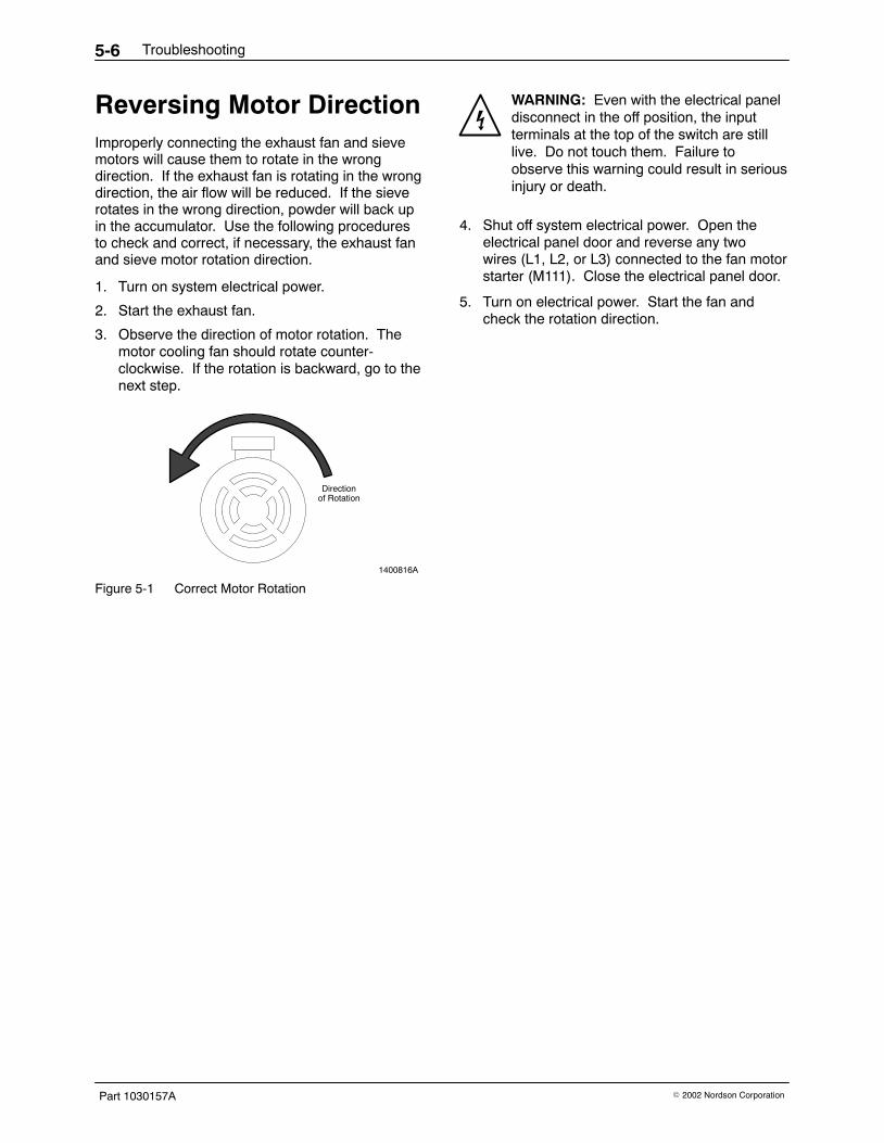
Reversing Motor DirectionImproperly connecting the exhaust fan and sievemotors will cause them to rotate in the wrongdirection. If the exhaust fan is rotating in the wrongdirection, the air flow will be reduced. If the sieverotates in the wrong direction, powder will back upin the accumulator. Use the following proceduresto check and correct, if necessary, the exhaust fanand sieve motor rotation direction.
1. Turn on system electrical power.
2. Start the exhaust fan.
3. Observe the direction of motor rotation. Themotor cooling fan should rotate counter-clockwise. If the rotation is backward, go to thenext step.
1400816A
Directionof Rotation
Figure 5-1 Correct Motor Rotation
WARNING: Even with the electrical paneldisconnect in the off position, the inputterminals at the top of the switch are stilllive. Do not touch them. Failure toobserve this warning could result in seriousinjury or death.
4. Shut off system electrical power. Open theelectrical panel door and reverse any twowires (L1, L2, or L3) connected to the fan motorstarter (M111). Close the electrical panel door.
5. Turn on electrical power. Start the fan andcheck the rotation direction.
Troubleshooting 5-7
Part 1030157A� 2002 Nordson Corporation
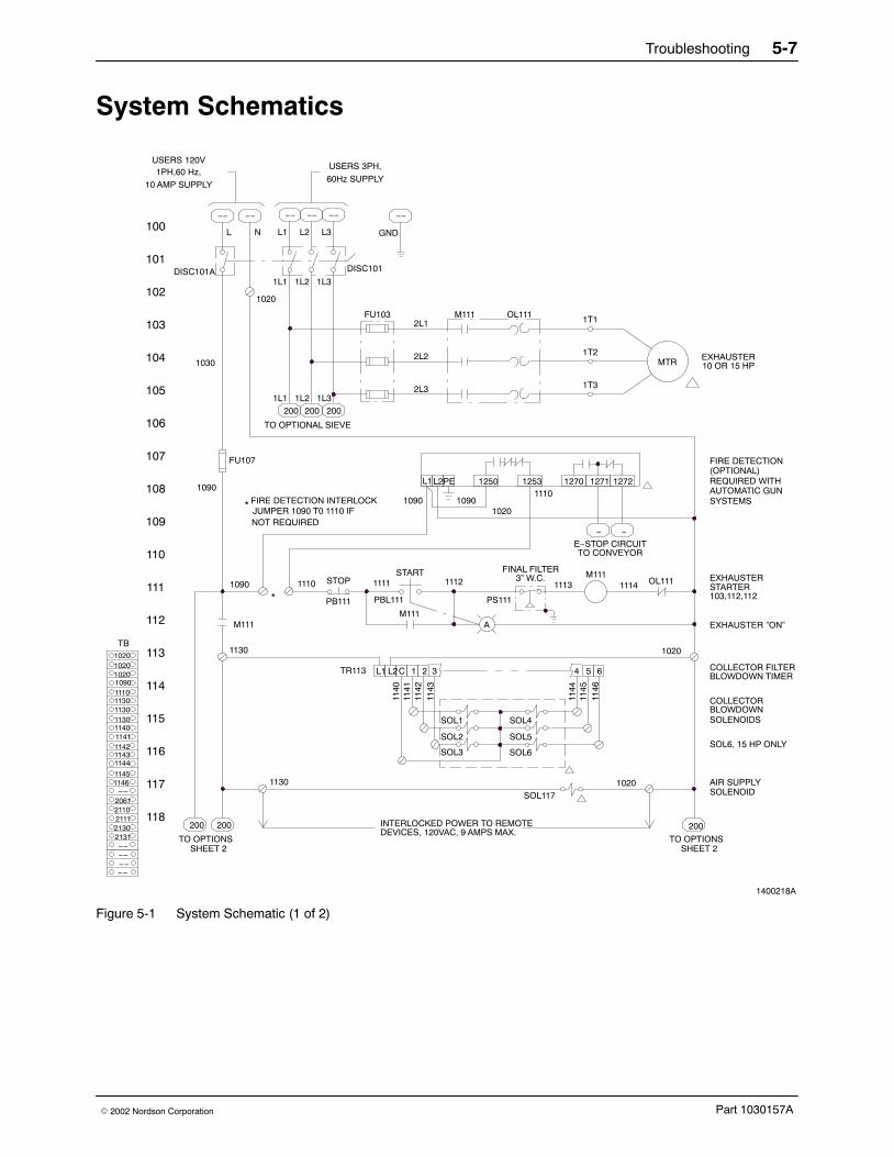
System Schematics
5
1400218A
103,112,112
SOL2
SOL3
SOL1115
114
113
112
1130
1130
M111
INTERLOCKED POWER TO REMOTEDEVICES, 120VAC, 9 AMPS MAX.
PB111M111
PBL111
321CL2L1TR113
1140
PS111
A
BLOWDOWN TIMERCOLLECTOR FILTER
EXHAUSTER ”ON”
1020
BLOWDOWNSOLENOIDS
COLLECTOR
1110
FINAL FILTER
102
1110
NOT REQUIREDJUMPER 1090 T0 1110 IFFIRE DETECTION INTERLOCK
1090
109
111
110
108
107
1090*
*
FU107
1030
106
105
104
103
1020
STOPSTART
1111
1090
L1
1112 3” W.C.
1250
1090
PEL2
1020
1253
2L3
FU103
2L2
2L1M111 OL111
−−
1PH,60 Hz,
10 AMP SUPPLY
DISC101A
100
101
L
1L1 1L2
L1N L2
−− −− −−
DISC101
1L3
L3 GND
60Hz SUPPLY
−− −−
FIRE DETECTION
OL111
E−STOP CIRCUITTO CONVEYOR
1113M111
−
1114
−
1270 1271 1272
EXHAUSTERSTARTER
REQUIRED WITH(OPTIONAL)
SYSTEMSAUTOMATIC GUN
MTR
1T3
1T2
1T1
EXHAUSTER10 OR 15 HP
USERS 120VUSERS 3PH,
200200 200
1L1 1L2 1L3
TO OPTIONAL SIEVE
118
117
116
SOL1171020 AIR SUPPLY
SOLENOID
4 6
SOL5
SOL4
200 200
TO OPTIONSSHEET 2
TO OPTIONSSHEET 2
1141
1142
1143
1144
1145
TB
SOL6
1146
SOL6, 15 HP ONLY
200
102010201020
113011101090
11431142
1130
11401141
1130
1145
1144
21302131
1146−−
211121102061
−−
−−−−−−
Figure 5-1 System Schematic (1 of 2)

Troubleshooting5-8
Part 1030157A � 2002 Nordson Corporation
1400218A
213
212
1130
202
209
211
210
208
207
1130
206
205
204
203
1020
105
200
201
1L1 1L2
118 118 105
1L3
FROM SHEET 1
105
3L3
FU201
3L2
3L1M206 OL206
MTR
2T3
2T2
2T1
1/6 AS VIBRATORYSIEVE (OPTIONAL)
LS206BLS206A
LT207A
201,211(OPTIONAL)
SIEVE ”ON”
2060SIEVE LIMIT SWITCHES
1130 20622061 OL206M206
SIEVE STARTER
(OPTIONAL)
2130
2110
SS212X
TDR213
MAN
(9) (5)
AUTOX
OFF
JUMPER IF NO SIEVE PROVIDED
TDR213POWDER LEVEL SENSOR
PRX211
2131 (14)
* M206 2111
SOL211
*
DELAY−ON 0−3 MIN.TRANSFER PUMP
SET SELECTOR TO(13)
TRANSFER PUMP1020
JUMPER IF VIBRATORY SIEVE PROVIDED✥
✥
211X1 & M.
1/2 AS ROTARY
CR208(14) (13)
CR208
PBL208
A
START1090 2080
1090
118
CR208
NO SIEVETRANSFER ENABLE(SIEVE OPTION)
NO SIEVETRANSFER ENABLE
209,210
(9) (5) (SIEVE OPTION)
TRANSFER PUMP
PRIMARY FILTER
ENCLOSURE VENT
QUICK DISCONNECT (DISCONNECTED)
PRESSURE SWITCH (ADJUST.)
ENCLOSURE PNEUMATIC SCHEMATIC
ADJUST TO OPENCONTACT AT 3.0 in.
H O PRESSURE
LEGEND
2PS111
LO
HIFINAL FILTER
HI
LO
GA10
GA5
Figure 5-2 System Schematic (2 of 2)
Repair 6-1
Part 1030157A� 2002 Nordson Corporation
Section 6Repair
WARNING: Allow only qualified personnelto perform the following tasks. Follow thesafety instructions in this document and allother related documentation.
NOTE: Use only approved Nordson Corporationreplacement parts. Refer to Parts for part numbersand ordering information. Contact your NordsonCorporation representative for more information.
Final Filter Replacement
WARNING: Before performing thisprocedure, shut off electrical power at thesystem electrical panel. Lock and tag theswitch. Failure to observe this warningcould result in personal injury.
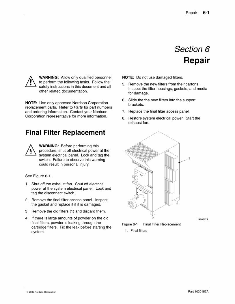
See Figure 6-1.
1. Shut off the exhaust fan. Shut off electricalpower at the system electrical panel. Lock andtag the disconnect switch.
2. Remove the final filter access panel. Inspectthe gasket and replace it if it is damaged.
3. Remove the old filters (1) and discard them.
4. If there is large amounts of powder on the oldfinal filters, powder is leaking through thecartridge filters. Fix the leak before starting thesystem.
NOTE: Do not use damaged filters.
5. Remove the new filters from their cartons.Inspect the filter housings, gaskets, and mediafor damage.
6. Slide the the new filters into the supportbrackets.
7. Replace the final filter access panel.
8. Restore system electrical power. Start theexhaust fan.
1400817A
1
Figure 6-1 Final Filter Replacement
1. Final filters
Repair6-2
Part 1030157A � 2002 Nordson Corporation
Cartridge FilterReplacement
Removal1. Remove the color module from the powder
booth as described in the Color Changeprocedure in Operation.
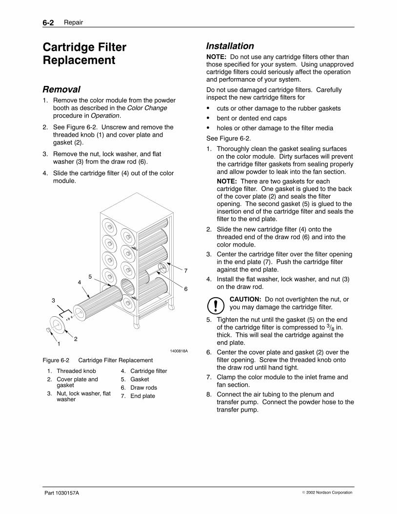
2. See Figure 6-2. Unscrew and remove thethreaded knob (1) and cover plate andgasket (2).
3. Remove the nut, lock washer, and flatwasher (3) from the draw rod (6).
4. Slide the cartridge filter (4) out of the colormodule.
1400818A
12
3
46
57
Figure 6-2 Cartridge Filter Replacement
1. Threaded knob2. Cover plate and
gasket3. Nut, lock washer, flat
washer
4. Cartridge filter5. Gasket6. Draw rods7. End plate
InstallationNOTE: Do not use any cartridge filters other thanthose specified for your system. Using unapprovedcartridge filters could seriously affect the operationand performance of your system.
Do not use damaged cartridge filters. Carefullyinspect the new cartridge filters for
� cuts or other damage to the rubber gaskets
� bent or dented end caps
� holes or other damage to the filter media
See Figure 6-2.
1. Thoroughly clean the gasket sealing surfaceson the color module. Dirty surfaces will preventthe cartridge filter gaskets from sealing properlyand allow powder to leak into the fan section.
NOTE: There are two gaskets for eachcartridge filter. One gasket is glued to the backof the cover plate (2) and seals the filteropening. The second gasket (5) is glued to theinsertion end of the cartridge filter and seals thefilter to the end plate.
2. Slide the new cartridge filter (4) onto thethreaded end of the draw rod (6) and into thecolor module.
3. Center the cartridge filter over the filter openingin the end plate (7). Push the cartridge filteragainst the end plate.
4. Install the flat washer, lock washer, and nut (3)on the draw rod.
CAUTION: Do not overtighten the nut, oryou may damage the cartridge filter.
5. Tighten the nut until the gasket (5) on the endof the cartridge filter is compressed to 3/8 in.thick. This will seal the cartridge against theend plate.
6. Center the cover plate and gasket (2) over thefilter opening. Screw the threaded knob ontothe draw rod until hand tight.
7. Clamp the color module to the inlet frame andfan section.
8. Connect the air tubing to the plenum andtransfer pump. Connect the powder hose to thetransfer pump.
Repair 6-3
Part 1030157A� 2002 Nordson Corporation
Color Module FluidizingPlate ReplacementFluidizing plate replacement is only necessary if theplate is contaminated or damaged.
Preparation1. Pulse the cartridge filters, then start the transfer
pump and pump the powder out the colormodule hopper.
2. Remove the color module from the fan sectionas described in the Color Change procedure inOperation.
3. Remove the transfer pump and bottom two orfour cartridge filters from the color module.
4. Vacuum the remaining powder out of the colormodule hopper. Vacuum the hopper andfluidizing plate and wipe them clean with damp,lint-free cloths. Do not use tack cloths.
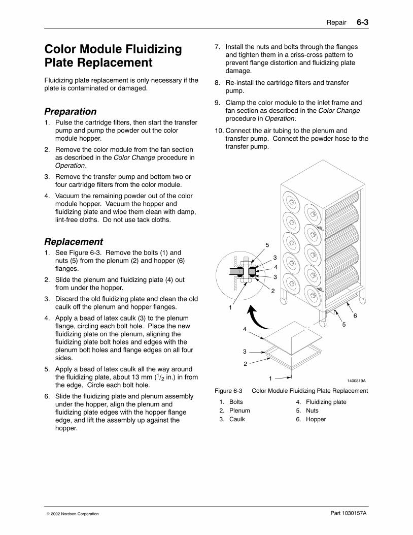
Replacement1. See Figure 6-3. Remove the bolts (1) and
nuts (5) from the plenum (2) and hopper (6)flanges.
2. Slide the plenum and fluidizing plate (4) outfrom under the hopper.
3. Discard the old fluidizing plate and clean the oldcaulk off the plenum and hopper flanges.
4. Apply a bead of latex caulk (3) to the plenumflange, circling each bolt hole. Place the newfluidizing plate on the plenum, aligning thefluidizing plate bolt holes and edges with theplenum bolt holes and flange edges on all foursides.
5. Apply a bead of latex caulk all the way aroundthe fluidizing plate, about 13 mm (1/2 in.) in fromthe edge. Circle each bolt hole.
6. Slide the fluidizing plate and plenum assemblyunder the hopper, align the plenum andfluidizing plate edges with the hopper flangeedge, and lift the assembly up against thehopper.
7. Install the nuts and bolts through the flangesand tighten them in a criss-cross pattern toprevent flange distortion and fluidizing platedamage.
8. Re-install the cartridge filters and transferpump.
9. Clamp the color module to the inlet frame andfan section as described in the Color Changeprocedure in Operation.
10. Connect the air tubing to the plenum andtransfer pump. Connect the powder hose to thetransfer pump.
1400819A1
2
3
4
1
2
3
5
5
3
4
6
Figure 6-3 Color Module Fluidizing Plate Replacement
1. Bolts2. Plenum3. Caulk
4. Fluidizing plate5. Nuts6. Hopper

Repair6-4
Part 1030157A � 2002 Nordson Corporation
Pulse Valve Replacement See Figure 6-4.
The pulse valves are connected directly to the airmanifold (6) in the open end of the fan section. Toavoid connecting the valves to the wrong solenoids,either mark the pilot air tubing or remove andreplace one valve at a time. Incorrect connectionswill cause the valves to open in the wrong order.
The pulse air solenoid valves are mounted on theside of the fan section. Timer board terminal 1 iswired to solenoid valve 1. Solenoid valve 1 isconnected by air tubing to pulse valve 1. The restof the solenoids and valves are connected in thesame way.
WARNING: Before performing thefollowing procedure, shut off the systemcompressed-air supply and relieve thesystem air pressure. Shut off and lockoutelectrical power at a disconnect switchahead of the system electrical panel.Failure to observe this warning could resultin personal injury.
1. Remove the color module as described in theColor Change procedure in Operation.
2. Disconnect the pilot air tubing from the elbowfitting (1).
3. Remove the pilot valve (5) and extensionpipe (3) assembly from the coupling (2).
4. Remove the extension pipe assembly from thepilot valve.
5. Wrap PTFE tape around the threads of thecoupling and extension pipe.
6. Install the new pilot valve on the extension pipe.When the pilot valve is tightened to form anair-tight seal, the extension pipe must be at aright angle to the centerline of the pilot valveinlet port.
7. Install the pilot valve on the coupling. When thepilot valve is tightened on the coupling to forman air-tight seal, the extension pipe must belevel and the nozzles (4) must point into thecenter of the cartridge filter openings.
8. Connect the pilot air tubing to the elbow fitting.
1400820A
CL
1 2 3 4 5
1
TIMER BOARD
654321L
2
3
4
5
11
7
89
10
5
12
3
5
4
6
Figure 6-4 Pulse Valve Replacement
1. Elbow fitting2. Coupling3. Extension pipe4. Nozzle
5. Pulse valve6. Air manifold7. 14-gauge white wire jumper to all
solenoids8. 14-gauge red wire (positive)
9. 14-gauge white common wire10. 6-mm tubing to each solenoid11. Solenoid enclosure
Repair 6-5
Part 1030157A� 2002 Nordson Corporation
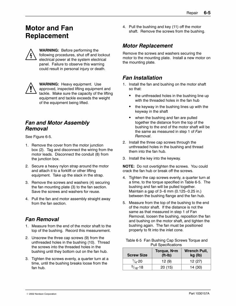
Motor and FanReplacement
WARNING: Before performing thefollowing procedures, shut off and lockoutelectrical power at the system electricalpanel. Failure to observe this warningcould result in personal injury or death.
WARNING: Heavy equipment. Useapproved, inspected lifting equipment andtackle. Make sure the capacity of the liftingequipment and tackle exceeds the weightof the equipment being lifted.
Fan and Motor AssemblyRemovalSee Figure 6-5.
1. Remove the cover from the motor junctionbox (2). Tag and disconnect the wiring from themotor leads. Disconnect the conduit (8) fromthe junction box.
2. Secure a heavy nylon strap around the motorand attach it to a forklift or other liftingequipment. Take up the slack in the strap.
3. Remove the screws and washers (4) securingthe fan mounting plate (3) to the fan section.Save the screws and washers for reuse.
4. Pull the fan and motor assembly straight awayfrom the fan section.
Fan Removal 1. Measure from the end of the motor shaft to the
top of the bushing. Record this measurement.
2. Unscrew the three cap screws (9) from theunthreaded holes in the bushing (10). Threadthe screws into the threaded holes in thebushing until they bottom out on the fan hub.
3. Tighten the screws evenly, a quarter turn at atime, until the bushing breaks loose from thefan hub.
4. Pull the bushing and key (11) off the motorshaft. Remove the screws from the bushing.
Motor Replacement Remove the screws and washers securing themotor to the mounting plate. Install a new motor onthe mounting plate.
Fan Installation 1. Install the fan and bushing on the motor shaft
so that:
� the unthreaded holes in the bushing line upwith the threaded holes in the fan hub
� the keyway in the bushing lines up with thekeyway in the shaft
� when the bushing and fan are pulledtogether the distance from the top of thebushing to the end of the motor shaft will bethe same as measured in step 1 of FanRemoval.
2. Install the three cap screws through theunthreaded holes in the bushing and threadthem into the fan hub.
3. Install the key into the keyway.
NOTE: Do not overtighten the screws. You couldcrack the fan hub or break off the screws.
4. Tighten the cap screws evenly, a quarter turn ata time, to the torque specified in Table 6-5. Thebushing and fan will be pulled together.Maintain a gap of 3−6 mm (0.125−0.25 in.)between the bushing flange and the fan hub.
5. Measure from the top of the bushing to the endof the motor shaft. If the distance is not thesame as that measured in step 1 of FanRemoval, loosen the bushing, reposition the fanand bushing on the motor shaft, and tighten thebushing again. The fan must be positionedproperly to fit into the inlet cone.
Table 6-5 Fan Bushing Cap Screws Torque andPull Specifications
Screw SizeTorque, N�m
(ft-lb)Wrench Pull,
kg (lb)1/4-20 12 (9) 12 (27)5/16-18 20 (15) 14 (30)

Repair6-6
Part 1030157A � 2002 Nordson Corporation
1400821A
1
2
3
4
5
6
7
9
66
7
10
11
8
Figure 6-5 Fan and Motor Replacement
1. Motor2. Junction box3. Mounting plate4. Screws and washers
5. Screws and washers6. Fan7. Bushing8. Motor shaft
9. Conduit10. Cap screws11. Key
Fan and Motor AssemblyInstallation 1. Lift the fan and motor assembly and guide it
carefully back into the fan section, making surethe fan fits inside the cone.
2. Secure the mounting plate to the fan sectionwith the screws and washers.
3. Remove the final filters as described in FinalFilter Replacement.
4. See Figure 6-6. Check the fan position. Thebottom of the fan should be 3−6 mm(0.125−0.250 in.) inside the inlet cone.

Repair 6-7
Part 1030157A� 2002 Nordson Corporation
5. Rotate the fan and make sure it is not rubbingagainst the inlet cone. The gap between thefan and the cone should be the same all theway around. If it is not, loosen the conefasteners and adjust the cone position.
1400822A
3−6 mm(0.125−0.250 in.)
21
3
Figure 6-6 Checking Fan Position and Clearance
1. Fan2. Inlet cone
3. Cone fasteners
6. Re-install the final filters.
7. See Figure 6-5. Remove the cover from themotor junction box (2). Connect the conduit (9)to the motor junction box and the wiring to themotor leads. Install the cover.
8. Turn on the system electrical power and startthe fan. Make sure the fan
� rotates in the direction shown by the arrowon the side of the motor. Refer toReversing Motor Direction in theTroubleshooting section.
� does not rub against the inlet cone.
Repair6-8
Part 1030157A � 2002 Nordson Corporation

Parts 7-1
Part 1030157A� 2002 Nordson Corporation
Section 7Parts
Introduction To order parts, call the Nordson Finishing Customer Support Center at (800) 433−9319 or contact your localNordson representative.
Use the illustrations and parts lists to locate and describe parts correctly.
Using the Illustrated Parts List Numbers in the Item column correspond to numbers that identify parts in illustrations following each partslist. The code NS (not shown) indicates that a listed part is not illustrated. A dash (—) is used when the partnumber applies to all parts in the illustration.
The number in the Part column is the Nordson Corporation part number. A series of dashes in this column(- - - - - -) means the part cannot be ordered separately.
The Description column gives the part name, as well as its dimensions and other characteristics whenappropriate. Indentions show the relationships between assemblies, subassemblies, and parts.
� If you order the assembly, items 1 and 2 will be included.
� If you order item 1, item 2 will be included.
� If you order item 2, you will receive item 2 only.
The number in the Quantity column is the quantity required per unit, assembly, or subassembly. The codeAR (As Required) is used if the part number is a bulk item ordered in quantities or if the quantity perassembly depends on the product version or model.
Letters in the Note column refer to notes at the end of each parts list. Notes contain important informationabout usage and ordering. Special attention should be given to notes.
Item Part Description Quantity Note— 0000000 Assembly 11 000000 � Subassembly 2 A2 000000 � � Part 1
Parts7-2
Part 1030157A � 2002 Nordson Corporation
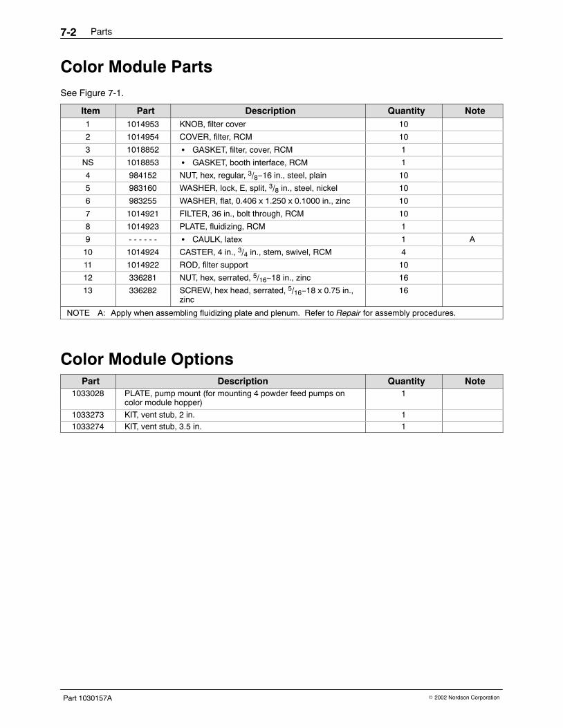
Color Module PartsSee Figure 7-1.
Item Part Description Quantity Note1 1014953 KNOB, filter cover 10
2 1014954 COVER, filter, RCM 10
3 1018852 � GASKET, filter, cover, RCM 1
NS 1018853 � GASKET, booth interface, RCM 1
4 984152 NUT, hex, regular, 3/8−16 in., steel, plain 10
5 983160 WASHER, lock, E, split, 3/8 in., steel, nickel 10
6 983255 WASHER, flat, 0.406 x 1.250 x 0.1000 in., zinc 10
7 1014921 FILTER, 36 in., bolt through, RCM 10
8 1014923 PLATE, fluidizing, RCM 1
9 - - - - - - � CAULK, latex 1 A
10 1014924 CASTER, 4 in., 3/4 in., stem, swivel, RCM 4
11 1014922 ROD, filter support 10
12 336281 NUT, hex, serrated, 5/16−18 in., zinc 16
13 336282 SCREW, hex head, serrated, 5/16−18 x 0.75 in.,zinc
16
NOTE A: Apply when assembling fluidizing plate and plenum. Refer to Repair for assembly procedures.
Color Module OptionsPart Description Quantity Note
1033028 PLATE, pump mount (for mounting 4 powder feed pumps oncolor module hopper)
1
1033273 KIT, vent stub, 2 in. 11033274 KIT, vent stub, 3.5 in. 1

Parts 7-3
Part 1030157A� 2002 Nordson Corporation
1400823A
13
9
8
1
2
4
6
7
11
5
12
10
3
9
Figure 7-1 Color Module Parts

Parts7-4
Part 1030157A � 2002 Nordson Corporation
Fan Section PartsSee Figure 7-2.
Item Part Description Quantity Note1 1014961 VALVE, solenoid, enclosure, 5 port 12 1014962 VALVE, solenoid, shut off 13 1032826 FINAL FILTER, RCM 44 1014960 VALVE, diaphragm, pulse, 1 in. 55 1014956 FOOT, leveler, RCM − A6 1014952 CONE INLET, BI22, RCM 17 1014950 FAN WHEEL, BI22, counter-clockwise, RCM 18 1022543 MOTOR, extend shaft, 10 hp, 200 Volt 1 B8 1014957 MOTOR, extend shaft, 10 hp, 230/460 Volt 1 B8 1022544 MOTOR, extend shaft, 10 hp, 380 Volt 1 B8 1014958 MOTOR, extend shaft, 10 hp, 575 Volt 1 B
NOTE A: Quantity varies depending on base length: 9 ft − 6, 12 ft − 8, 15 ft − 8.
B: Order correct motor for your voltage.
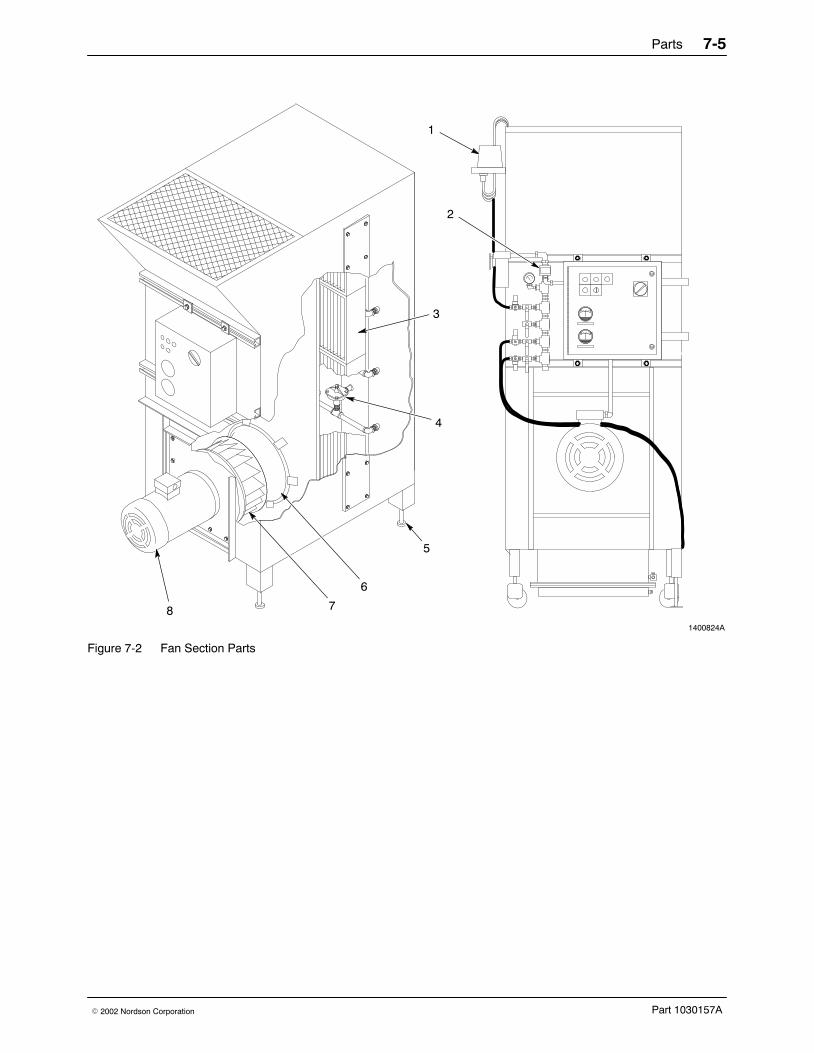
Parts 7-5
Part 1030157A� 2002 Nordson Corporation
1400824A
7
3
4
0 5
0 10
8
6
1
2
5
Figure 7-2 Fan Section Parts

Parts7-6
Part 1030157A � 2002 Nordson Corporation
Canopy/BaseSee Figure 7-3.
Item Part Description Quantity Note1 1034139 CASTER, 6 in. flanged 4 A2 1014929 TRACK, roller base 2 A
NS 1014956 FOOT, leveler, RCM, base 6 B
NOTE A: Used with the roll-on/roll-off system. For field upgrade from fixed to roll-on/roll-off, order kit 1033275,which includes casters and tracks.
B: Used with the fixed-base system in place of the flanged casters and roller base track.
NS: Not Shown
1400216A
1
2
Figure 7-3 Casters and Track Parts

Parts 7-7
Part 1030157A� 2002 Nordson Corporation
Electrical Panel See Figure 7-4. System schematics are in Troubleshooting.
Item Part Description Quantity NoteStandard System without options
DISC101 See chart Disconnect, non-fused 1 ABBDISC101 OXZ549 Disconnect, handle 1 ABBDISC101 OHB80J6 Disconnect, extended shaft 1 ABB
DISC101A OA1G10 Aux. contact, disconnect 1 ABBM111 See chart Contactor, overload 1 Allen BradleyOL111 See chart Overload, motor 1 Allen BradleyM111 100-SA10 Contact, auxiliary 1 Allen Bradley
FU103 See chart Fuse, J-type, time delay 3 GouldFU103 See chart Fuse block 1 MarathonFU107 TRM10 Fuse, control 1 GouldFU107 − Fuse block 1 −PBL111 − Pushbutton, illum., amber, LED 1 TelemecaniquePBL111 − Pushbutton, base 1 TelemecaniquePB111 ZBABA9 Pushbutton, head, red 1 TelemecaniquePB111 ZB4BZ102 Pushbutton, base 1 Telemecanique
TB, FU107, Options − DIN rail AR −TB − Terminals 25 −
TR113 DNC-T2005-B10 Timer board 1 NCCGA10 2-5010 Minihelic gauge, 0−10 in. w.c. 1 DwyerGA5 2-5005 Minihelic gauge, 0−5 in. w.c. 1 Dwyer
PS111 1910-5 Pressure switch 1 DwyerPS111, GA5, GA10 KQ2E06-00 Bulkhead union, 6 mm 2 SMC
PS111 KQ2H06-01S Male connector, 6 mm x 1/8 in.NPT
1 SMC
ATM1 AN203-KMB Breather vent 1 SMCPS111, GA5 KQ2U06-99 Plug-in Y, 6 mm 1 SMC
PS111, GA5, GA10 − Tubing, 6 mm AR −
Automatic Transfer OptionSS210 − Switch, selector, 3-position,
maintained1 Telemecanique
TDR211 GT5Y-2SN1A100 Timer, delay-on 1 IDECTDR211 SY4S-05 Base, timer 1 IDEC
Sieve OptionM206 100-C09D10 Contactor, motor 1 Allen BradleyOL206 See chart Overload, motor 1 Allen BradleyFU201 See chart Fuse, class CC, time delay 3 GouldFU201 − Fuse block, DIN rail 1 −LT207 − Light, indicating, amber, LED 1 TelemecaniqueCR208 RH2B-UAC120V Relay, control, 120V 1 IDECCR208 SH2B-05 Base, relay 1 IDECPBL208 − Pushbutton, illum., amber, LED 1 Telemecanique
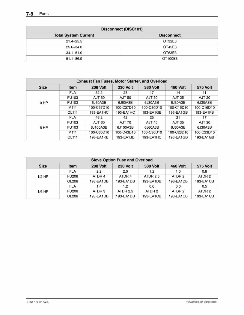
Parts7-8
Part 1030157A � 2002 Nordson Corporation
Disconnect (DISC101)
Total System Current Disconnect21.4−25.5 OT32E3
25.6−34.0 OT45E3
34.1−51.0 OT63E3
51.1−86.9 OT100E3
Exhaust Fan Fuses, Motor Starter, and Overload
Size Item 208 Volt 230 Volt 380 Volt 460 Volt 575 Volt
10 HP
FLA 32.2 28 17 14 11FU103 AJT 60 AJT 50 AJT 30 AJT 25 AJT 20FU103 6J60A3B 6J60A3B 6J30A3B 6J30A3B 6J30A3BM111 100-C37D10 100-C37D10 100-C30D10 100-C16D10 100-C16D10OL111 193-EA1HC 193-EA1HC 193-EA1GB 193-EA1GB 193-EA1FB
15 HP
FLA 46.2 42 25 21 17FU103 AJT 60 AJT 70 AJT 45 AJT 35 AJT 30FU103 6J100A3B 6J100A3B 6J60A3B 6J60A3B 6J30A3BM111 100-C60D10 100-C43D10 100-C30D10 100-C23D10 100-C23D10OL111 193-EA1KE 193-EA1JD 193-EA1HC 193-EA1GB 193-EA1GB
Sieve Option Fuse and Overload
Size Item 208 Volt 230 Volt 380 Volt 460 Volt 575 Volt
1/2 HP
FLA 2.2 2.0 1.2 1.0 0.8FU206 ATDR 4 ATDR 4 ATDR 2.5 ATDR 2 ATDR 2OL206 193-EA1DB 193-EA1DB 193-EA1DB 193-EA1DB 193-EA1CB
1/6 HP
FLA 1.4 1.2 0.6 0.6 0.5FU206 ATDR 3 ATDR 2.5 ATDR 2 ATDR 2 ATDR 2OL206 193-EA1DB 193-EA1DB 193-EA1CB 193-EA1CB 193-EA1CB
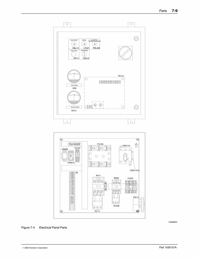
Parts 7-9
Part 1030157A� 2002 Nordson Corporation
1400825A
Primary Filters
Final Filters
TRANSFER
PS111
SS210
FU201M206
OL206
GA10
GA5
0 5
0 10
A
SIEVE
LT207
M111
OL111
FU103DISC101
TRM−10 OR EQUAL10 AMP MAXIMUM
DISC101ATB
TDR213
FAN STOP
PBL111
FAN START
PB111
A
FU107
PBL208
NO SIEVE
A
TRANSFER ENABLE
CR208
102010201020
113011101090
11431142
1130
11401141
1130
11451144
1146−−
2061
−−
2110211121302131
−−−−−−
TR113
Figure 7-4 Electrical Panel Parts

Parts7-10
Part 1030157A � 2002 Nordson Corporation