vantage mechanical installation manual - … documentation/vantage...determine installation type •...
TRANSCRIPT
page 1 www.CentSys.com
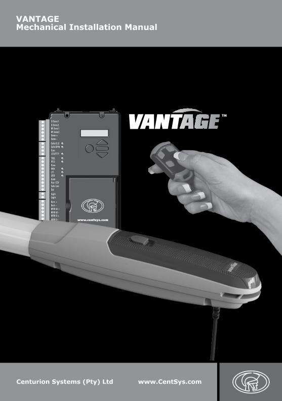
VANTAGE Mechanical Installation Manual
Centurion Systems (Pty) Ltd www.CentSys.com
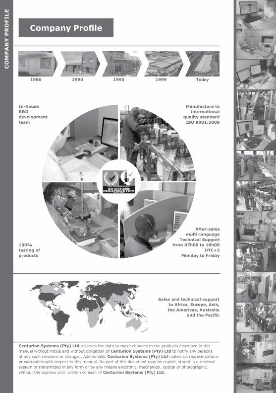
After-sales
multi-languageTechnical Support
from 07h00 to 18h00 UTC+2
Monday to Friday
Manufacture tointernational
quality standardISO 9001:2008
100% testing of products
In-houseR&Ddevelopmentteam
Centurion Systems (Pty) Ltd reserves the right to make changes to the products described in this manual without notice and without obligation of Centurion Systems (Pty) Ltd to notify any persons of any such revisions or changes. Additionally, Centurion Systems (Pty) Ltd makes no representations or warranties with respect to this manual. No part of this document may be copied, stored in a retrieval system or transmitted in any form or by any means electronic, mechanical, optical or photographic, without the express prior written consent of Centurion Systems (Pty) Ltd.
1986 1990 1995 1999 Today
CO
MP
AN
Y P
RO
FILE
Company Profile
Sales and technical support to Africa, Europe, Asia, the Americas, Australia
and the Pacific
www.CentSys.com
SAFETYFIRST IMPORTANT SAFETY INSTRUCTIONS
1. General Description
2. Icons Used in this Manual
3. Specifications
3.1. Physical Dimensions
3.2. Technical Specifications
3.3. V-Series Controller
3.4. Lightning Protection
3.5. Power Supply
3.6. Allowable Gate Mass
3.7. Allowable Wind Load
4. Product Identification
4.1. V-Series Wall Box
5. Required Tools and Equipment
6. Preparation of Site
6.1 General Considerations for the Installation
6.2. Determine Gate Opening Angle
6.3. Key Terms Used in this Section
6.4. Side Wall Limitation - Inward Opening
6.5. Pillar Hinge Depth Limitation - Inward Opening
6.6. Wall Bracket Mounting Methods
6.7. Strength of the Gate and Gate Bracket
7. Cabling Requirements
8. Critical Installation Checklist
9. Operator Installation - Inward Opening Gate(s)
10. Operator Installation - Outward Opening Gate(s)
page 5
Contents
CO
NT
EN
TS
page 8
page 9
page 10
page 10
page 11
page 12
page 12
page 12
page 13
page 14
page 15
page 16
page 17
page 18
page 18
page 19
page 20
page 20
page 21
page 22
page 24
page 25
page 26
page 27
page 36
page 4 www.CentSys.com
STEP1
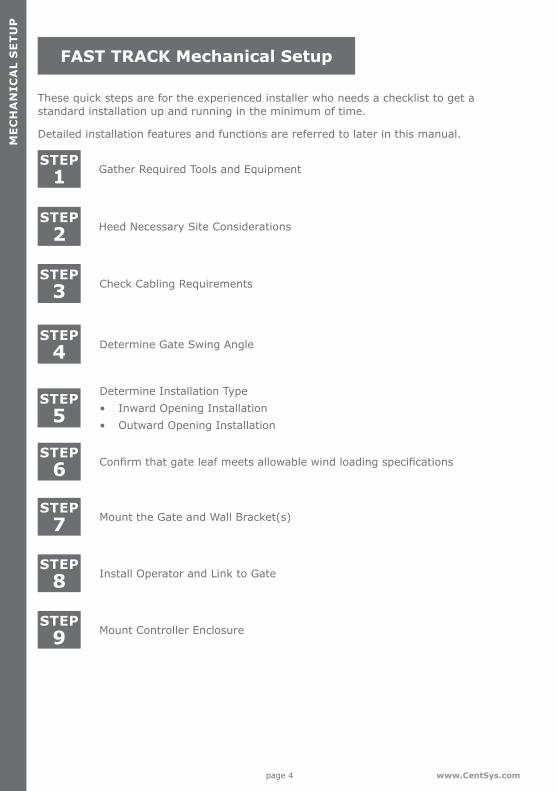
These quick steps are for the experienced installer who needs a checklist to get a standard installation up and running in the minimum of time.
Detailed installation features and functions are referred to later in this manual.
Gather Required Tools and Equipment
STEP2
STEP3
Heed Necessary Site Considerations
Check Cabling Requirements
STEP4
Determine Gate Swing Angle
STEP5
STEP6
STEP7
STEP8
STEP9
Confirm that gate leaf meets allowable wind loading specifications
Determine Installation Type• Inward Opening Installation• Outward Opening Installation
Mount the Gate and Wall Bracket(s)
Install Operator and Link to Gate
Mount Controller Enclosure
FAST TRACK Mechanical Setup
ME
CH
AN
ICA
L S
ET
UP

page 5www.CentSys.com
ATTENTIONTo ensure the safety of people and possessions, it is important that you read all the following instructions.
Incorrect installation or incorrect use of the product could cause serious harm to people.
The installer, being either professional or DIY, is the last person on the site who can ensure that the operator is safely installed, and that the whole system can be operated safely.
IMPORTANT SAFETY INSTRUCTIONS
Warnings for the Installer CAREFULLY READ AND FOLLOW ALL INSTRUCTIONS before beginning to install the product.
• All installation, repair, and service work to this product must be carried out by a suitably qualified person
• This appliance is not intended for use by persons (including children) with reduced physical, sensory or mental capabilities, or lack of experience and knowledge, unless they have been given supervision or instruction concerning use of the appliance by a person responsible for their safety
• Do not activate your gate unless you can see it and can determine that its area of travel is clear of people, pets, or other obstructions
• NO ONE MAY CROSS THE PATH OF A MOVING GATE; always keep people and objects away from the gate and its area of travel
• NEVER LET CHILDREN OPERATE OR PLAY WITH THE GATE CONTROLS
• Secure all easily-accessed gate opener controls in order to prevent unauthorised use of the gate
• Do not in any way modify the components of the automated system
• Do not install the equipment in an explosive atmosphere: the presence of flammable gasses or fumes is a serious danger to safety
• Before attempting any work on the system, cut electrical power to the operator and disconnect the batteries
• The Mains power supply of the automated system must be fitted with an all-pole switch with contact opening distance of 3mm or greater; use of a 5A hydraulic breaker with all-pole circuit break is recommended
• Make sure that an earth leakage circuit breaker with a threshold of 30mA is fitted upstream of the system
IMP
OR
TA
NT
SA
FET
Y IN
ST
RU
CT
ION
SS
AFE
TY
FIRS
T

page 6 www.CentSys.com
• Never short-circuit the battery and do not try to recharge the batteries with power supply units other than that supplied with the product, or manufactured by Centurion Systems (Pty) Ltd
• Make sure that the earthing system is correctly constructed, and that all metal parts of the system are suitably earthed
• Safety devices must be fitted to the installation to guard against mechanical movement risks such as crushing, dragging and shearing
• It is recommended that at least one warning indicator light be fitted to every system• Always fit the warning signs visibly to the inside and outside of the gate• The installer must explain and demonstrate the manual operation of the gate in case
of an emergency, and must hand the User Guide/Warnings over to the user• The installer must explain these safety instructions to all persons authorised to use
this gate, and be sure that they understand the hazards associated with automated gates
• Do not leave packing materials (plastic, polystyrene, etc.) within reach of children as such materials are potential sources of danger
• Dispose of all waste products like packing materials, worn-out batteries etc, according to local regulations
• Always check the obstruction detection system, and safety devices for correct operation
• Neither Centurion Systems (Pty) Ltd, nor its subsidiaries, accept any liability caused by improper use of the product, or for use other than that for which the automated system was intended
• This product was designed and built strictly for the use indicated in this documentation; any other use, not expressly indicated here, could compromise the service life/operation of the product and/or be a source of danger
• Everything not expressly specified in these instructions is not permitted
IMP
OR
TA
NT
SA
FET
Y I
NS
TR
UC
TIO
NS
SA
FET
Y F
IRS
T
Never run the operator directly from the battery! Doing so will cause damage to the operator. Only run the operator from the V-Series Controller.

page 7www.CentSys.com
This section has been left blank intentionally.
page 8 www.CentSys.com
The VANTAGE linear swing gate motor, available in two models with actuation strokes of 400mm and 500mm, respectively, has been designed to automate a wide variety of swing gates, from single light-domestic gates to heavy industrial double swing gates.
The fail-safe and fully-redundant Position and Collision Detection System has been designed and tested to set the standard in safety of operation and to provide an unparalleled level of reliability and durability in operation.
The gate Travel Limits are managed by a sealed double-redundant opto-electronic system that has been designed not only to ensure ultra-reliable operation, but also to ensure precise position and trajectory control. This enables very accurate and reliable collision detection to ensure safe operation even under trying conditions.
This guide covers the mechanical installation of your new VANTAGE swing gate operator.
SE
CT
ION
1G
EN
ER
AL
DE
SC
RIP
TIO
N
1. General Description
VANTAGE swing gate operators can be installed on both inward- and outward opening swing gates. Please see the relevant sections for each type of installation, paying attention to any site preparation that needs to be made before the operators are installed.
page 9www.CentSys.com
SE
CT
ION
2IC
ON
S U
SE
D IN
TH
IS M
AN
UA
L
2. Icons Used in this Manual
This icon indicates tips and other information that could be useful during the installation.
This icon denotes variations and other aspects that should be considered during installation.
This icon indicates warning, caution or attention! Please take special note of critical aspects that MUST be adhered to in order to prevent injury.

page 10 www.CentSys.com
SE
CT
ION
3S
PE
CIF
ICA
TIO
NS
3.1. Physical Dimensions
1000mm retracted
1400mm extended
95
mm
Ø100mm
400mmextended
piston stroke
500mmextended
piston stroke
FIGURE 1. VANTAGE 400 OVERALL DIMENSIONS
FIGURE 2. VANTAGE 500 OVERALL DIMENSIONS
1600mm extended
95
mm
1100mm retracted
Ø100mm
3. Specifications
page 11www.CentSys.com
SE
CT
ION
3S
PE
CIFIC
AT
ION
S
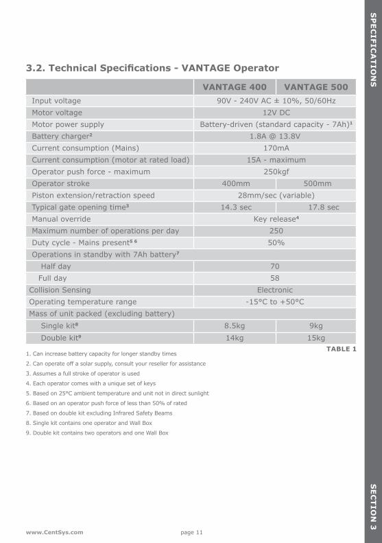
3.2. Technical Specifications - VANTAGE Operator
VANTAGE 400 VANTAGE 500Input voltage 90V - 240V AC ± 10%, 50/60HzMotor voltage 12V DCMotor power supply Battery-driven (standard capacity - 7Ah)1
Battery charger2 1.8A @ 13.8VCurrent consumption (Mains) 170mA Current consumption (motor at rated load) 15A - maximumOperator push force - maximum 250kgfOperator stroke 400mm 500mmPiston extension/retraction speed 28mm/sec (variable)Typical gate opening time3 14.3 sec 17.8 secManual override Key release4 Maximum number of operations per day 250Duty cycle - Mains present5 6 50% Operations in standby with 7Ah battery7
Half day 70Full day 58
Collision Sensing ElectronicOperating temperature range -15°C to +50°CMass of unit packed (excluding battery)
Single kit8 8.5kg 9kgDouble kit9 14kg 15kg
1. Can increase battery capacity for longer standby times
2. Can operate off a solar supply, consult your reseller for assistance
3. Assumes a full stroke of operator is used
4. Each operator comes with a unique set of keys
5. Based on 25°C ambient temperature and unit not in direct sunlight
6. Based on an operator push force of less than 50% of rated
7. Based on double kit excluding Infrared Safety Beams
8. Single kit contains one operator and Wall Box
9. Double kit contains two operators and one Wall Box
TABLE 1

page 12 www.CentSys.com
SE
CT
ION
3S
PE
CIF
ICA
TIO
NS
3.3. V-Series Controller
Maximum motor current per channel 15A (fused)
Maximum input voltage 14.4V DC
Standby current draw 48mA
Maximum solenoid current draw 2A DC
Maximum auxillary output current 3A (Resettable Electronic Fuse)
Collision detection Current sense and redundant-optical
Position and trajectory control Redundant optical
Temperature range -20°C to +60°C
Onboard receiver type Code-hopping multichannel
Receiver code storage capacity 64 transmitter buttons
Receiver frequency 433MHZ TABLE 2
3.5. Power Supply
Nominal input voltage 90V - 240V AC ±10% @ 50/60Hz
AC current draw (maximum) 170mA
Temperature range -20°C to +60°C
Battery charger output current (dependant on PSU input voltage)
90V AC input: 1.2A @ 13.8V 240V AC input: 1.8A @ 13.8V
TABLE 3
3.4. Lightning ProtectionThe V-Series Controller utilises the same proven surge protection philosophy that is used in all our products. While this does not guarantee that the unit will not be damaged in the event of a lightning strike or power surge, it greatly reduces the likelihood of such damage occurring. The earth return for the surge protection is provided via the mains power supply earth. In order to ensure that the surge protection is effective, it is essential that the unit is properly earthed.
page 13www.CentSys.com
SE
CT
ION
3S
PE
CIFIC
AT
ION
S
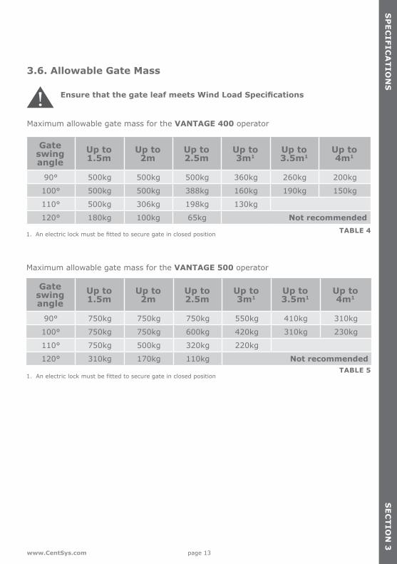
3.6. Allowable Gate Mass
Ensure that the gate leaf meets Wind Load Specifications
Gate swing angle
Up to 1.5m
Up to 2m
Up to 2.5m
Up to 3m1
Up to 3.5m1
Up to 4m1
90° 500kg 500kg 500kg 360kg 260kg 200kg
100° 500kg 500kg 388kg 160kg 190kg 150kg
110° 500kg 306kg 198kg 130kg
120° 180kg 100kg 65kg Not recommendedTABLE 41. An electric lock must be fitted to secure gate in closed position
Gate swing angle
Up to 1.5m
Up to 2m
Up to 2.5m
Up to 3m1
Up to 3.5m1
Up to 4m1
90° 750kg 750kg 750kg 550kg 410kg 310kg
100° 750kg 750kg 600kg 420kg 310kg 230kg
110° 750kg 500kg 320kg 220kg
120° 310kg 170kg 110kg Not recommended
Maximum allowable gate mass for the VANTAGE 500 operator
TABLE 51. An electric lock must be fitted to secure gate in closed position
Maximum allowable gate mass for the VANTAGE 400 operator
page 14 www.CentSys.com
SE
CT
ION
3S
PE
CIF
ICA
TIO
NS
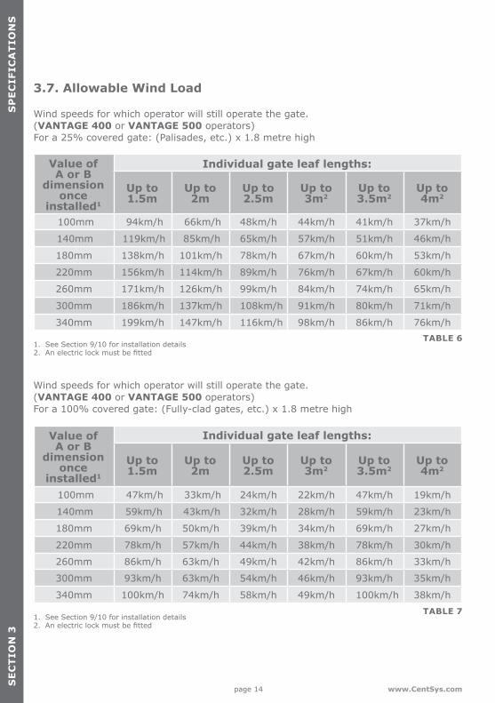
Wind speeds for which operator will still operate the gate. (VANTAGE 400 or VANTAGE 500 operators) For a 25% covered gate: (Palisades, etc.) x 1.8 metre high
Value of A or B
dimension once
installed1
Individual gate leaf lengths:
Up to 1.5m
Up to 2m
Up to 2.5m
Up to 3m2
Up to 3.5m2
Up to 4m2
100mm 94km/h 66km/h 48km/h 44km/h 41km/h 37km/h
140mm 119km/h 85km/h 65km/h 57km/h 51km/h 46km/h
180mm 138km/h 101km/h 78km/h 67km/h 60km/h 53km/h
220mm 156km/h 114km/h 89km/h 76km/h 67km/h 60km/h
260mm 171km/h 126km/h 99km/h 84km/h 74km/h 65km/h
300mm 186km/h 137km/h 108km/h 91km/h 80km/h 71km/h
340mm 199km/h 147km/h 116km/h 98km/h 86km/h 76km/h
Wind speeds for which operator will still operate the gate. (VANTAGE 400 or VANTAGE 500 operators) For a 100% covered gate: (Fully-clad gates, etc.) x 1.8 metre high
Value of A or B
dimension once
installed1
Individual gate leaf lengths:
Up to 1.5m
Up to 2m
Up to 2.5m
Up to 3m2
Up to 3.5m2
Up to 4m2
100mm 47km/h 33km/h 24km/h 22km/h 47km/h 19km/h
140mm 59km/h 43km/h 32km/h 28km/h 59km/h 23km/h
180mm 69km/h 50km/h 39km/h 34km/h 69km/h 27km/h
220mm 78km/h 57km/h 44km/h 38km/h 78km/h 30km/h
260mm 86km/h 63km/h 49km/h 42km/h 86km/h 33km/h
300mm 93km/h 63km/h 54km/h 46km/h 93km/h 35km/h
340mm 100km/h 74km/h 58km/h 49km/h 100km/h 38km/h
TABLE 6
TABLE 7
1. See Section 9/10 for installation details2. An electric lock must be fitted
1. See Section 9/10 for installation details2. An electric lock must be fitted
3.7. Allowable Wind Load

page 15www.CentSys.com
4. Product Identification
SE
CT
ION
4P
RO
DU
CT
IDE
NT
IFICA
TIO
N
FIGURE 3. KIT IDENTIFICATION
5
6
1
2
3
4
7
1. Keys are specific to each operator - key number must be recorded
1
2
8
9
10
11
12
1. Gate Bracket pin2. 14mm snap ring3. VANTAGE gate operator
(complete assembly)4. Wall Bracket5. Wall Bracket mounting plate6. Mechanical Installation Manual
7. Gate operator keys1
8. Stainless steel cap screw M5 x 259. Origin clamp10. M5 barrel nut11. Gate Bracket12. Gate Warning Decal

page 16 www.CentSys.com
1. 12V 7.2Ah Battery 1 2. V-Series Controller with built-in
receiver3. V-Series User Guide
4. V-Series Electrical Setup & Commissioning Guide
5. Charger 6. Code-hopping remote controls
FIGURE 4. V-SERIES WALL BOx INCLUDING CHARGER AND CONTROLLER
3
4
6
1
52
SE
CT
ION
4P
RO
DU
CT
ID
EN
TIF
ICA
TIO
N
4.1. V-Series Wall Box
1. Batteries can be of a larger capacity for longer power failure autonomy and are not included in the kit; Consult your local authorised dealer for assistance
page 17www.CentSys.com
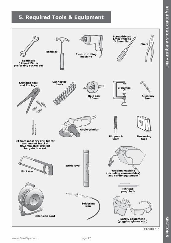
FIGURE 5
Spanners17mm/15mm
preferably socket set
Crimping tooland Pin lugs
Ø12mm masonry drill bit for wall mount bracket
Ø6.5mm steel drill bit for gate bracket
Connectorblock
Hole saw20mm
Angle grinder
Pin punch6mm
Hacksaw
Spirit level
Markingpen/chalk
Extension cord
Soldering iron
Safety equipment (goggles, gloves etc.)
Welding machine(including consumables)
and safety equipment
Measuringtape
Allen key5mm
G-clampsx2
Electric drillingmachine
Screwdrivers6mm Phillips3.5mm Flat
Hammer
Pliers
5. Required Tools & Equipment
SE
CT
ION
5R
EQ
UIR
ED
TO
OLS
& E
QU
IPM
EN
T
page 18 www.CentSys.com
6.1. General Consideration for the InstallationAlways recommend the fitment of additional safety equipment such as safety edges and Safety Beams (i5 or Photon), for additional protection against entrapment or other mechanical risks.
Check that no pipes or electrical cables are in the way of the intended installation.
Check that enough space is available for the gate operator with the gate in the required open position (see Figure 6).
If the swing gate leaf is longer than 2.5 metres, ensure that an electric lock can be fitted.
For security reasons, never fit an operator on the outside of the gate, where the public has access to it (refer to the instructions for an Outward-opening swing gate).
Never run an operator directly off the 12V battery.
Install the gate operator only if:
• It will not pose a hazard to the public• There is sufficient clearance to a roadway and/or public thoroughfares• The installation will meet all municipal and/or local authority requirements once
completed• The gate mass, leaf width, wind loading and application is within the operator
specifications• The gate is in good working order, meaning:
• that it swings freely;• does not move on its own if left in any position;• each gate leaf is strong and rigid;
• Once installed, there is sufficient clearance between moving parts during operation of the gate to reduce the risk of personal injury and/or entrapment
• It is recommended that Pushbuttons and Keyswitches, if fitted, be positioned in such a way that the gate is in line of sight of the user
6. Preparation of Site
SE
CT
ION
6P
RE
PA
RA
TIO
N O
F S
ITE
page 19www.CentSys.com
SE
CT
ION
6P
RE
PA
RA
TIO
N O
F SIT
E
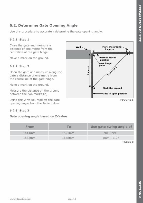
6.2. Determine Gate Opening AngleUse this procedure to accurately determine the gate opening angle:
FIGURE 6
1 metre
1 m
etre
Gate in closed position
Gate hinge point
Gate in open position
Mark the ground
Distan
ce Z
Mark the groundWall
6.2.1. Step 1
Close the gate and measure a distance of one metre from the centreline of the gate hinge.
Make a mark on the ground.
6.2.2. Step 2
Open the gate and measure along the gate a distance of one metre from the centreline of the gate hinge.
Make a mark on the ground.
Measure the distance on the ground between the two marks (Z).
Using this Z-Value, read off the gate opening angle from the Table below.
6.2.3. Step 3
Gate opening angle based on Z-Value
From To Use gate swing angle of
1414mm 1521mm 90° - 99°
1532mm 1638mm 100° - 110°TABLE 8

page 20 www.CentSys.com
SE
CT
ION
6P
RE
PA
RA
TIO
N O
F S
ITE
6.4. Side Wall Limitation - Inward Opening Figure 7 shows the side wall limitations for an Inward opening gate. The operator must be installed in accordance with these limitations. If the wall minimum cannot be achieved, consider using an outward swing configuration.
FIGURE 7. SIDE WALL LIMITATION FOR INWARD OPENING GATE
Wall minimum
must be greater than 200mm
Side wall
Wall Gate in closed position
Gate in open position
Gate swing angle
Gate hinge point
6.3. Key Terms Used in this Section6.3.1. Pillar maximum
The maximum allowable distance measured from the centre of the gate hinge to the edge of the pillar.
6.3.2. Wall minimum
This value denotes the minimum amount of space needed to install the operator and is measured from the side wall to the gate when the gate is in the open position.

page 21www.CentSys.com
SE
CT
ION
6P
RE
PA
RA
TIO
N O
F SIT
E
6.5. Pillar Hinge Depth Limitation - Inward OpeningFigure 8 shows the pillar hinge depth limitation for an Inward opening gate. An operator must be installed in accordance with these limitations to ensure that it does not interfere with the operation of the gate during movement. The hinge depth of the gate on the pillar, needs to be checked against the pillar maximum values in Table 9 to determine if the installation is possible. If the hinge depth of the gate is excessive, the gate may have to be relocated on the pillar to achieve the required pillar maximum values.
FIGURE 8. PILLAR HINGE DEPTH LIMITATION FOR INWARD OPENING GATE
Pillar maximum
Wall Gate in closed position
Gate in open position
Gate swing angle
Gate hinge point
Operator Pillar Maximum Swing Gate Angle
VANTAGE 400 175mm 90°
VANTAGE 400 155mm 100°
VANTAGE 400 145mm 110°
VANTAGE 500 245mm 90°
VANTAGE 500 235mm 100°
VANTAGE 500 230mm 110°TABLE 9

page 22 www.CentSys.com
SE
CT
ION
6P
RE
PA
RA
TIO
N O
F S
ITE
6.6. Wall Bracket Mounting MethodsThe following recommended methods may be used to install the operator.
6.6.1. Through-wall
Applications:
• Pre-fabricated walling• For heavy gates operating
frequently
6.6.2. Chemical anchors
Applications:
• Masonry pillars• Frequent use
6.6.3. Welding
Application:
• Steel pillars
FIGURE 9
FIGURE 11
Pillar
Steel pillar
Wall Bracket
Wall Bracket
Through-wall bolt
Welding machine
FIGURE 10
Pillar
Wall Bracket
Chemical anchor

page 23www.CentSys.com
SE
CT
ION
6P
RE
PA
RA
TIO
N O
F SIT
E
6.6.4. Sleeve anchors
Applications:
• Lighter gates• Domestic
6.6.5. Rawl bolts
Applications:
• Lighter gates• Domestic
FIGURE 12
FIGURE 13
Pillar
Pillar
Wall Bracket
Wall Bracket
Sleeve anchor
Rawl bolt
page 24 www.CentSys.com
SE
CT
ION
6P
RE
PA
RA
TIO
N O
F S
ITE
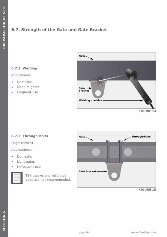
6.7. Strength of the Gate and Gate Bracket
6.7.1. Welding
Applications:
• Domestic• Medium gates• Frequent use
FIGURE 14
FIGURE 15
Gate
Gate Through-bolts
Gate Bracket
Gate Bracket
Welding machine
6.7.2. Through-bolts
(high-tensile)
Applications:
• Domestic• Light gates• Infrequent use
TEK screws and mild steel bolts are not recommended.
page 25www.CentSys.com
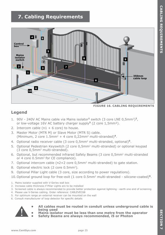
Control box
Mains isolator switch
9
5
9
6
610
1
2 3
8
4
7
FIGURE 16. CABLING REQUIREMENTS
Control box
350mm cable loop
Mains isolator switch
9
5
9
6
610
1
2 3
8
4
7
7. Cabling Requirements
SE
CT
ION
7C
AB
LING
RE
QU
IRE
ME
NT
S
Legend1. 90V - 240V AC Mains cable via Mains isolator1 switch (3 core LNE 0,5mm2)2,
or low-voltage 16V AC battery charger supply3 (2 core 1,5mm²).2. Intercom cable (n1 + 6 core) to house.3. Master Motor (MTR M) or Slave Motor (MTR S) cable.
(Minimum, 2 core 1.5mm2 + 4 core 0,22mm2 multi-stranded)4.4. Optional radio receiver cable (3 core 0,5mm2 multi-stranded, optional)5. 5. Optional Pedestrian Keyswitch (2 core 0,5mm2 multi-stranded) or optional keypad
(3 core 0,5mm2 multi-stranded).6. Optional, but recommended infrared Safety Beams (3 core 0,5mm2 multi-stranded
or 4 core 0.5mm2 for CE compliance).7. Optional intercom cable (n2+2 core 0,5mm2 multi-stranded) to gate station.8. Optional electric lock (2 core 0.5mm2).9. Optional Pillar Light cable (3 core, size according to power regulations).10. Optional ground loop for free-exit (1 core 0.5mm2 multi-stranded - silicone-coated)6.
• All cables must be routed in conduit unless underground cable is being used
• Mains isolator must be less than one metre from the operator• Safety Beams are always recommended, i5 or Photon
1. Mains isolator supplied with V-Series wall box2. Increase cable thickness if Pillar Lights are to be installed3. Screened cable is always recommended to provide better protection against lightning - earth one end of screening 4. Please use V-Series cabling. Order reference: CABLEVEC68 5. For optimum range an external receiver can be mounted on the wall6. Consult manufacturer of loop detector for specific details
page 26 www.CentSys.com
8. Critical Installation Checklist
SE
CT
ION
8C
RIT
ICA
L IN
ST
ALL
AT
ION
CH
EC
KLI
ST
The following is a list of critical requirements that must be adhered to in order to ensure reliable operation of your VANTAGE operator(s):
• Ensure that the Wall Bracket is securely anchored• Make sure that the operator’s maximum stroke is being utilised• Only use V-Series cable for the installation• Leave a 350mm long loop in the cable• Fit an electric gate lock if the leaf width is greater than 3 metres• Ensure that the opening and closing angles conform to the installation guidelines• Ensure that your gate and operator(s) are equipped to deal with Wind Loading
(refer to the Table 6 and 7 on page 14)
Never run the operator directly from the battery! Doing so will cause damage to the operator. Only run the operator from the V-Series Controller.

page 27www.CentSys.com
SE
CT
ION
9
21. Solar Panel Wiring9. Operator Installation - Inward Opening Gates
OP
ER
AT
OR
INS
TA
LLAT
ION
- INW
AR
D O
PE
NIN
G G
AT
ES
Ensure that the gate mass does not exceed the specifications on page 14.
Figure 17 illustrates the values corresponding to the Inward Opening Gate Installation Tables.
FIGURE 17. BRACKET POSITION - INWARD OPENING GATE
A
BE
Wall
VANTAGEoperator
Gate in closed position
9.2. Step 1Measure the E-Value and ensure that it does not exceed values shown in Figure 8 and Table 10 on page 21.
Depending on the gate opening angle determined in Section 6.2 and the E-Value measured, determine the installation distances for the A- and B-Value using the Tables shown on pages 29 to 31.
9.1. Key terms used in this section9.1.1. E-ValueThe distance from the centre of the gate hinge to the edge of the pillar.
9.1.2. A-ValueThe horizontal distance from the Wall Bracket/pivot pin to the center of the gate hinge.
9.1.3. B-ValueThe vertical distance from the Wall Bracket/pivot pin to the center of the gate hinge.
page 28 www.CentSys.com
SE
CT
ION
9O
PE
RA
TO
R I
NS
TA
LLA
TIO
N -
IN
WA
RD
OP
EN
ING
GA
TE
S
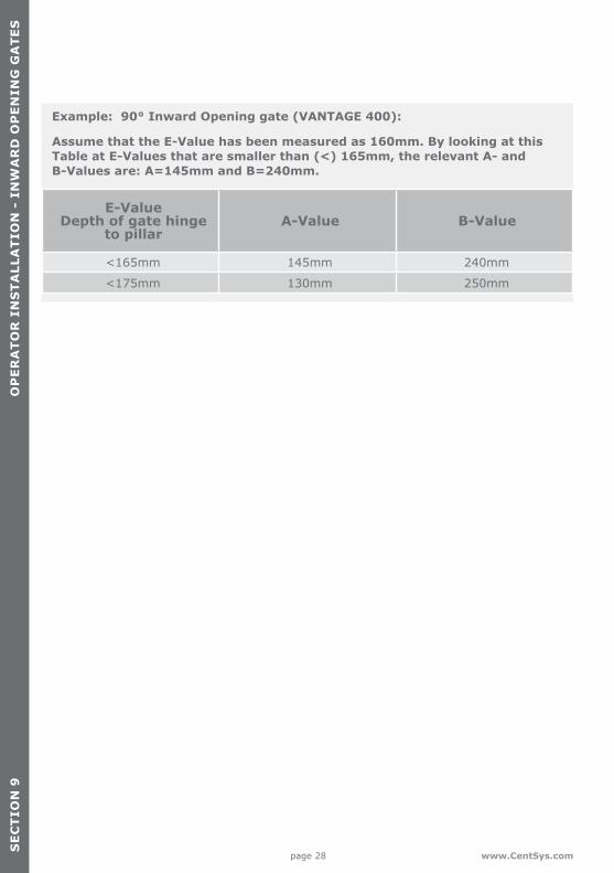
Example: 90° Inward Opening gate (VANTAGE 400):
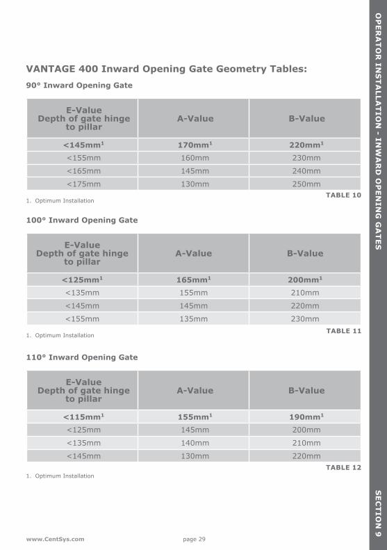
Assume that the E-Value has been measured as 160mm. By looking at this Table at E-Values that are smaller than (<) 165mm, the relevant A- and B-Values are: A=145mm and B=240mm.
E-Value Depth of gate hinge
to pillarA-Value B-Value
<165mm 145mm 240mm
<175mm 130mm 250mm
page 29www.CentSys.com
SE
CT
ION
9
VANTAGE 400 Inward Opening Gate Geometry Tables: 90° Inward Opening Gate
E-Value Depth of gate hinge
to pillar A-Value B-Value
<145mm1 170mm1 220mm1
<155mm 160mm 230mm
<165mm 145mm 240mm
<175mm 130mm 250mm
100° Inward Opening Gate
E-Value Depth of gate hinge
to pillarA-Value B-Value
<125mm1 165mm1 200mm1
<135mm 155mm 210mm
<145mm 145mm 220mm
<155mm 135mm 230mm
1. Optimum Installation TABLE 11
1. Optimum Installation TABLE 10
1. Optimum InstallationTABLE 12
110° Inward Opening Gate
E-Value Depth of gate hinge
to pillarA-Value B-Value
<115mm1 155mm1 190mm1
<125mm 145mm 200mm
<135mm 140mm 210mm
<145mm 130mm 220mm
OP
ER
AT
OR
INS
TA
LLAT
ION
- INW
AR
D O
PE
NIN
G G
AT
ES

page 30 www.CentSys.com
SE
CT
ION
9
VANTAGE 500 Inward Opening Gate Geometry Tables:90° Inward Opening Gate
E -Value Depth of gate hinge
to pillarA-Value B-Value
<190mm1 205mm1 280mm1
<205mm 195mm 290mm
<215mm 180mm 300mm
<225mm 170mm 310mm
<235mm 155mm 320mm
<245mm 140mm 330mmTABLE 131. Optimum Installation
100° Inward Opening Gate
E-Value Depth of gate hinge
to pillarA-Value B-Value
<175mm1 195mm1 260mm1
<185mm 185mm 270mm
<195mm 175mm 280mm
<205mm 165mm 290mm
<215mm 155mm 300mm
<225mm 145mm 310mm
<235mm 135mm 320mmTABLE 14
1. Optimum Installation
OP
ER
AT
OR
IN
ST
ALL
AT
ION
- I
NW
AR
D O
PE
NIN
G G
AT
ES

page 31www.CentSys.com
SE
CT
ION
9
VANTAGE 500 Inward Opening Gate Geometry Table:110° Inward Opening Gate
E-Value Depth of gate hinge
to pillarA-Value B-Value
<150mm1 190mm1 240mm1
<160mm 185mm 250mm
<170mm 175mm 260mm
<180mm 170mm 270mm
<190mm 160mm 280mm
<205mm 150mm 290mm
<210mm 145mm 300mm
<220mm 135mm 310mm
<230mm 125mm 320mmTABLE 15
1. Optimum Installation
OP
ER
AT
OR
INS
TA
LLAT
ION
- INW
AR
D O
PE
NIN
G G
AT
ES
page 32 www.CentSys.com
SE
CT
ION
9
FIGURE 18. WALL BRACKET HEIGHT
Wal
l Bra
cket
Min
imu
m 1
25
mm
Gate Gate Bracket position
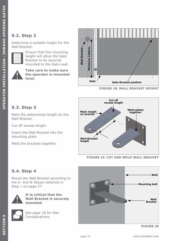
9.2. Step 2 Determine a suitable height for the Wall Bracket.
Ensure that this mounting height will allow the Gate Bracket to be securely mounted to the Gate Leaf.
Take care to make sure the operator is mounted level.
9.3. Step 3Mark the determined length on the Wall Bracket.
Cut off excess length.
Insert the Wall Bracket into the mounting plate.
Weld the brackets together.
FIGURE 19. CUT AND WELD WALL BRACKET
Mark length on bracket
Weld plates together
Cut off excess length
Wall Bracket length
FIGURE 20
Wall
Mounting bolt
Wall Bracket
It is critical that the Wall Bracket is securely mounted.
See page 18 for Site Considerations.
9.4. Step 4Mount the Wall Bracket according to the A- and B-Values obtained in Step 1 on page 27.
OP
ER
AT
OR
IN
ST
ALL
AT
ION
- I
NW
AR
D O
PE
NIN
G G
AT
ES

page 33www.CentSys.com
SE
CT
ION
9
9.5. Step 5Fit the Gate Bracket to the VANTAGE.
FIGURE 21
PinGate Bracket
Origin clamp
VANTAGE operator
G-clamp
Gate in closed position
G-clamp or spot weld
Gate Bracket
VANTAGEoperator
WallWall Bracket
FIGURE 23
VANTAGE operator
WallBracket
FIGURE 22
Wall
Pin
9.6. Step 6Fit the motor end of the operator to the Wall Bracket.
Support the operator to prevent damage
OP
ER
AT
OR
INS
TA
LLAT
ION
- INW
AR
D O
PE
NIN
G G
AT
ES
9.7. Step 7Manually rotate the piston to the fully extended position, and then retract it by half to one full turn.
With the gate in the closed position, use a G-clamp or spot weld the Gate Bracket in position to temporarily hold the Gate Bracket in place.
The G-clamp should only be used to secure the Gate Bracket in place, and should never be used as a means of securing the operator piston arm as this could result in damage.

page 34 www.CentSys.com
SE
CT
ION
9
FIGURE 24
Gate in closed position
Set the origin clamp to the open limit
VANTAGEoperator
G-clamp
G-clamp
Gate in open position
Wall
9.9. Step 9If the gate opening angle is sufficient and the operator is utilising the majority of its stroke, then secure the Gate Bracket using the most appropriate means.
Remove the operator before welding, if welding is required.
If this is not the case or the operator does not have enough stroke for the gate to open fully, re-check the A- and B-Values from Table 10 on page 29 to Table 15 on page 31.
FIGURE 25
Gate Bracket
Welding machine
Bolt
Nuts
9.8. Step 8Manually release the operator using the key provided with the kit, and swing the gate to the desired open position.
Slide the origin clamp along the piston tube, right up to the end to the operator.
Secure origin clamp in place, and tighten properly with an Allen Key.
Gate
Gate Bracket
OR
OP
ER
AT
OR
IN
ST
ALL
AT
ION
- I
NW
AR
D O
PE
NIN
G G
AT
ES

page 35www.CentSys.com
SE
CT
ION
9
FIGURE 26
Attach warning labels to the inside and outside of the gate as shown.
The Mechanical part of the installation is now complete.
OP
ER
AT
OR
INS
TA
LLAT
ION
- INW
AR
D O
PE
NIN
G G
AT
ES
page 36 www.CentSys.com
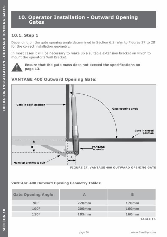
Ensure that the gate mass does not exceed the specifications on page 13.
10.1. Step 1Depending on the gate opening angle determined in Section 6.2 refer to Figures 27 to 28 for the correct installation geometry.
In most cases it will be necessary to make up a suitable extension bracket on which to mount the operator’s Wall Bracket.
10. Operator Installation - Outward Opening Gates
SE
CT
ION
10
OP
ER
AT
OR
IN
ST
ALL
AT
ION
- O
UT
WA
RD
OP
EN
ING
GA
TE
S
FIGURE 27. VANTAGE 400 OUTWARD OPENING GATE
Make up bracket to suit
A
B
Gate in closed position
Gate in open position
VANTAGE operator
Gate opening angle
VANTAGE 400 Outward Opening Gate:
VANTAGE 400 Outward Opening Geometry Tables:
Gate Opening Angle A B
90° 220mm 170mm
100° 200mm 160mm
110° 185mm 160mm TABLE 16
page 37 www.CentSys.com
SE
CT
ION
10
OP
ER
AT
OR
IN
ST
ALL
AT
ION
- O
UT
WA
RD
OP
EN
ING
GA
TE
S
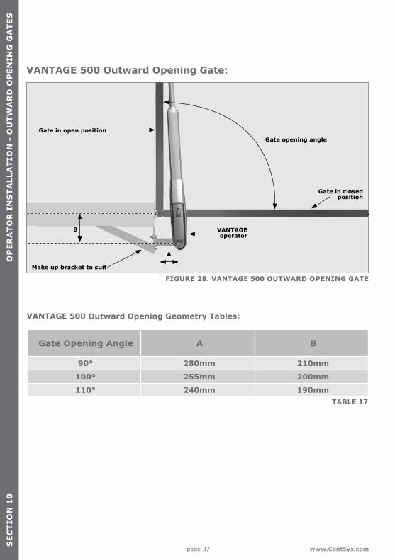
FIGURE 28. VANTAGE 500 OUTWARD OPENING GATE
Make up bracket to suit
B
Gate in closed position
Gate in open position
VANTAGE operator
Gate opening angle
VANTAGE 500 Outward Opening Gate:
VANTAGE 500 Outward Opening Geometry Tables:
Gate Opening Angle A B
90° 280mm 210mm
100° 255mm 200mm
110° 240mm 190mm
A
TABLE 17

page 38 www.CentSys.com
SE
CT
ION
10
10.2. Step 2 Determine a suitable height for the Wall Bracket.
Ensure that this mounting height will allow the Gate Bracket to be securely mounted to the Gate Leaf.
Take care to make sure the operator is mounted level.
FIGURE 31
FIGURE 29. BRACKET HEIGHT
Wall
Mounting bolt
Wall Bracket
Sturdy Custom bracket
Wal
l Bra
cket
Min
imu
m 1
25
mm
Gate Gate Bracket Position
FIGURE 30. CUT AND WELD WALL BRACKET
Mark length on bracket
Weld plates together
Cut off excess length
Wall Bracket length
10.3. Step 3Mark the determined length on the Wall Bracket.
Cut off the excess length.
Insert the Wall Bracket into the mounting plate.
Weld the brackets together.
10.4. Step 4Mount the Wall Bracket according to the A- and B-Values obtained in Step 1 on page 36.
It is critical that the Wall Bracket is securely mounted and is adequately rigid.
See page 18 for site considerations.
OP
ER
AT
OR
IN
ST
ALL
AT
ION
- O
UT
WA
RD
OP
EN
ING
GA
TE
S

page 39www.CentSys.com
SE
CT
ION
10
10.5. Step 5Fit the Gate Bracket to the VANTAGE.
FIGURE 32
PinGate Bracket
Origin clamp
VANTAGE operator
FIGURE 33
VANTAGE operator
Wall
Pin
Wall Bracket
FIGURE 34
Set the origin clamp to closed limit
G-clamp or spot weld
Gate in closed position
Wall Bracket
VANTAGEoperator
10.6. Step 6Fit the motor end of the operator to the Wall Bracket.
Support the operator to prevent damage
OP
ER
AT
OR
INS
TA
LLAT
ION
- OU
TW
AR
D O
PE
NIN
G G
AT
ES
10.7. Step 7Manually rotate the piston to the fully retracted position, and then extend it by half to one full turn.
With the gate in the closed position, use a G-clamp or spot weld the Gate Bracket in position to temporarily hold the Gate Bracket in place.
The G-clamp should only be used to secure the Gate Bracket in place, and should never be used as a means of securing the operator piston arm as this could result in damage.
page 40 www.CentSys.com
SE
CT
ION
10
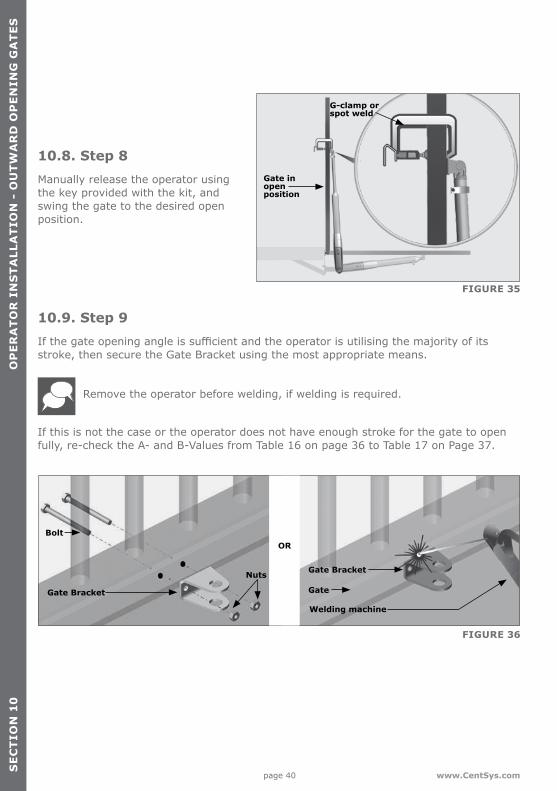
10.8. Step 8Manually release the operator using the key provided with the kit, and swing the gate to the desired open position.
FIGURE 35
G-clamp or spot weld
Gate in open position
10.9. Step 9If the gate opening angle is sufficient and the operator is utilising the majority of its stroke, then secure the Gate Bracket using the most appropriate means.
Remove the operator before welding, if welding is required.
If this is not the case or the operator does not have enough stroke for the gate to open fully, re-check the A- and B-Values from Table 16 on page 36 to Table 17 on Page 37.
Gate Bracket
Welding machine
Bolt
Nuts
Gate
Gate Bracket
OR
OP
ER
AT
OR
IN
ST
ALL
AT
ION
- O
UT
WA
RD
OP
EN
ING
GA
TE
S
FIGURE 36

page 41www.CentSys.com
SE
CT
ION
10
FIGURE 37
Attach warning labels to the inside and outside of the gate as shown.
The Mechanical part of the installation is now complete.
OP
ER
AT
OR
INS
TA
LLAT
ION
- OU
TW
AR
D O
PE
NIN
G G
AT
ES

page 42 www.CentSys.com
NO
TE
S
Notes

page 43www.CentSys.com
NO
TE
SNotes

page 44
Call Centurion Systems (Pty) Ltd . South AfricaHead Office: +27 11 699 2400
Call Technical Support: +27 11 699 2481from 07h00 to 18h00 (UTC+2)
Connect with us on:
facebook.com/CenturionSystems
YouTube.com/CenturionSystems
Twitter@askCenturion
Subscribe to the newsletter: www.CentSys.com/Subscribe
www.CentSys.com
DOC12381V100 - VANTAGE INSTALLATION MANUAL V1 GENERIC-06032015