vanderbilt university medical center planning | design
TRANSCRIPT

Mechanical, Plumbing and Electrical Design Guidelines And Construction Standards
VUMC - 09/17/18
1
Vanderbilt University Medical CenterPLANNING | DESIGN | CONSTRUCTION
MECHANICAL, PLUMBING AND ELECTRICAL DESIGN GUIDELINES
AND CONSTRUCTION STANDARDS
REVISED JUNE 2019

Mechanical, Plumbing and Electrical Design Guidelines And Construction Standards
VUMC - 09/17/18
2
Contents
1. General Provisions1.1 General 1.2 Mechanical Drawings, Diagrams and Sketches 1.3 Electrical Drawings, Diagrams, Sketches and Numbering Equipment Naming
Schemes 1.4 Demolition 1.5 Pipe Identification 1.6 Valve and Equipment Identification 1.7 Conduit and Junction Identification 1.8 Switchgear Switchboards Panelboards and Equipment Identification 1.9 Safety Instructions and Lock-out requirements 1.10 Cable System Supporting Structure 1.11 Equipment and Systems Testing 1.12 Inspections 1.13 Approved Contractors
2. Piping Specialties2.1 Steel Pipe 2.2 Copper Pipe 2.3 Cast Iron Soil and Vent Pipe 2.4 Plastic Pipe 2.5 Concrete Pipe 2.6 Stainless Pipe 2.7 Installation of Piping 2.8 Valves 2.9 Medical Gas Piping 2.10 Grooved Joint Couplings and Fittings
3. Motors and Drives3.1 General Motor and Drive Requirements 3.2 Motor Protection and Alarm 3.3 Voltage Controllers and Voltage Assistance Starting
4. Vibration Isolation4.1 Floor Mounted Spring Isolators 4.2 Spring Rubber Hangers 4.3 Rubber Neoprene Pads 4.4 Spring and Rubber Isolator Hangers 4.5 Flexible Pipe Connectors
5. Insulation5.1 General Requirements 5.2 Duct Insulation 5.3 Piping Insulation 5.4 Equipment Insulation

Mechanical, Plumbing and Electrical Design Guidelines And Construction Standards
VUMC - 09/17/18
3
6. Fire Protection
7. Plumbing Systems7.1 General Requirements 7.2 Backflow Preventers 7.3 Floor Drains and Trap Primers 7.4 Cleanouts 7.5 Natural Gas Connections 7.6 Acid Waste Piping and Equipment 7.7 Deionized/Distilled Water Piping and Equipment 7.8 Domestic Water Systems 7.9 Plumbing Fixtures 7.10 Ice Maker
8. Medical and Lab Gas Systems8.1 General Requirements 8.2 Medical Gas Alarm System 8.3 Piping Materials 8.4 Medical/Lab Vacuum Pumps 8.5 Medical/Lab Air Compressors
9. Water Systems9.1 HVAC Pumps 9.2 Hydronic Specialties 9.3 Chemical Water Treatment 9.4 Chillers 9.5 Cooling Towers 9.6 Hot Water Heating Coils
10. Steam Producing and Management Equipment10.1 Steam and Condensate Specialties 10.2 Humidifiers 10.3 Steam Heating Coils 10.4 Boilers 10.5 Condensate Return Pump
11. Air Side Equipment11.1 Air Handling Units 11.2 Fan Coil Units 11.3 Air Terminal Units 11.4 Fans 11.5 Filters 11.6 Unit Heaters 11.7 Electric Duct Heaters
12. Sheetmetal Ductwork and Accessories12.1 Duct Construction and Installation 12.2 Accessories
13. Controls and Facilities Management System13.1 General13.2 Front End Nomenclature

Mechanical, Plumbing and Electrical Design Guidelines And Construction Standards
VUMC - 09/17/18
4
13.3 Control System Alarms
14. HVAC Systems Test and Balances
15. Conduit Specialties15.1 Electrical Metallic Tubing (EMT Conduit) 15.2 Rigid Metal Conduit 15.3 Flexible Metal Conduit 15.4 Couplings, Connectors and Fittings. 15.5 Conduit Installation Methods 15.6 Wireway Cable Duct Cable Tray and Ladder 15.7 Communications Conduit Installation Procedures
16. Conductor Cable Insulation16.1 General Requirements 16.2 Low Voltage Cable 0-600Volts 16.3 4.16kV Medium Voltage Cables 16.4 13.8kV Medium Voltage Cables 16.5 Cable Color Coding 16.6 Voice/Data Cabling 16.7 Cable Testing
17. Fire Alarm and Detection
17.1 General Requirements 17.2 Initiation Devices and Circuits 17.3 Supervisory Devices and Circuits 17.4 Notification Devices and Circuits 17.5 Signaling Line Circuits 17.6 Power Supplies 17.7 System and Service
18. Electrical Systems18.1 Source and Transmission Voltage Levels 18.2 Unit Substations 18.3 Primary Switchgear and Automatic Transfer Bypass and Isolation Switches 18.4 Distribution Voltage Levels 18.5 Uninterruptible Power Supply Systems (UPS) and Batteries 18.6 Static Standby Generators 18.7 Emergency Switchboards, Synchronizing, Paralleling Devices and Control 18.8 Generator Fuel System 18.9 Lightning Protection 18.10 Transformer General Requirements 18.11 Liquid Immersed Transformers 18.12 Dry Type Encapsulated Transformers 18.13 MV Liquid immersed Transformer and Routine Tests
19. Exterior, Interior and Emergency Lighting Fixtures19.1 General Requirements19.2 Fluorescent Lighting Fixtures and Lamps

Mechanical, Plumbing and Electrical Design Guidelines And Construction Standards
VUMC - 09/17/18
5
19.3 Emergency Exit Lighting Fixtures and Lamps 19.4 Special Lighting Fixtures and Lamps for Physiological Monitoring
20. Telephone/Data Systems20.1 General Requirements 20.2 Telephone Distribution System 20.3 Voice and Data Communications 20.4 Voice and Data Cabling 20.5 Grounding Voice and Data System
21. Security System21.1 General Design Criteria 21.2 Equipment 21.3 System Installation
22. Specific Space Requirements and Design Criteria22.1 General Design Criteria 22.2 General Laboratory 22.3 Biosafety Level 3 (BL-3) Laboratory 22.4 Patient Room
• General Patient Room
• Infectious Isolation Room (TB)
• Protective Isolation Room (Myelo)22.5 Operating Room 22.6 Cath. Lab 22.7 Nuclear Medicine Suite 22.8 MRI Suite 22.9 Linear Accelerator Suite 22.10 Animal Care Area 22.11 Autopsy and Morgue 22.12 Vanderbilt Hospital and The Vanderbilt Clinic 22.13 Pharmacy Spaces 22.14 Medical Center North 22.15 Rooms Requiring Specific Pressure Relationships
23. Energy Efficiency and Conservation Requirements23.1 General Design Criteria 23.2 Building Envelope Requirements 23.3 Minimum Motor Efficiencies 23.4 Miscellaneous Energy Efficiency Requirements 23.5 Commissioning
24. Mechanical and Plumbing Details24.1 Mechanical Detail Index Reference to Appendix A 24.2 Plumbing Details Index Reference to Appendix A
25. O&M Closeout Documentation Requirements
Appendix A - Mechanical and Plumbing Details

Mechanical, Plumbing and Electrical Design Guidelines And Construction Standards
VUMC - 09/17/18
6
Appendix B - BSL-3 Laboratory Design Schematic

Mechanical, Plumbing and Electrical Design Guidelines And Construction Standards
VUMC - 09/17/18
7
Chapter
1 General Provisions
1.1 GENERAL
Content displayed in a red font represents information that has been added or revised since the last issue of these standards.
This document shall serve as minimum requirements for design and construction of mechanical systems for all Vanderbilt University Medical Center owned and leased buildings, both new and existing. Any design or construction not meeting or exceeding these minimum standards requires specific approval from Planning • Design • Construction.
It will be the Construction Manager and Consulting Engineer’s responsibility to review the standards established by Vanderbilt University Medical Center (VUMC) and, if they are not compatible with codes or excessively detrimental to project budget, bring such information to the attention of VUMC Planning • Design • Construction in writing.
Mechanical work includes plumbing, sprinkler, medical gas systems, controls, insulation, heating, ventilating, and air conditioning systems.
Electrical work includes Power Supply (15kV, 5kV 600V), transformers (oil filled/dry type), switchgear including metering and protection devices, switchboards including metering and protection devices, lighting, lighting controls (line and low voltage), convenience power (receptable), equipment/specialty system power, all line voltage power (above 100 volts), switchboards, panelboards, J-boxes, conduit, conduit bodies, disconnects, pull boxes, wireways, fire alarm, nurse call, telemetry and patient tracking systems, switches, devices, public address systems, magnetic door holders, RF shielding, CATV, satellite antenna systems, and all other electrical components necessary for the installation of a complete electrical system. Additionally, telecommunications/Data is part of the electrical work scope but has its’ own standards which are published by Vanderbilt Network Infrastructure. Refer to those standards for information relative to telecommunications systems.
The design and installation of electrical and mechanical systems shall comply with state and local health departments, environmental protection agency, and building codes, including plumbing codes, National Electrical Code (NEC) and with state and local ordinances.
Buildings and systems shall be designed and constructed in compliance with codes currently adopted by the Metro-Nashville Davidson County Codes Commission, which can be found at the following address: http://www.nashville.gov/Codes-Administration/Codes-Administration/Adopted-Codes-List.aspx

Mechanical, Plumbing and Electrical Design Guidelines And Construction Standards
VUMC - 09/17/18
8
Both inpatient and outpatient spaces shall be designed and constructed in accordance with the currently adopted Guidelines for Design and Construction of Health Care Facilities.
Ductwork construction, installation and ventilation systems shall comply with NFPA Standard 90A and SMACNA.
Sprinkler systems shall comply with NFPA Standard 13 and 14.
Electrical construction, installation and systems shall comply with NFPA Code 70, ANSI/IEEE, and NEC Codes
Fire detection and alarm systems including magnetic door holders, shall comply with NFPA Code 70, 99 and 101. For Healthcare NFPA 99 and for Generators NFPA 37 and 110.
Equipment shall be U.L. Listed and labeled as required in specific equipment chapters. Installation of systems shall comply with U.L. standards, where applicable.
Piping, fittings and valves shall be provided by domestic manufactures, unless specifically approved prior to installation. Where appropriate, components shall be marked clearly with the manufacturer’s name, weight and classification or working pressure.
Fittings, valves, and piping specialties shall be the products of a single manufacturer. Tools used for pipe preparation and/or installation shall be of the same manufacturer as the piping components.
The completed systems shall pass any and all tests required by the authorities having jurisdiction.
Mechanical and Electrical equipment shall comply with regulatory noise and safety standards.
Mechanical systems and equipment shall be guaranteed against faulty material or workmanship for a period of not less than one year from the date of substantial completion or acceptance by the project commissioning agent or beneficial use, whichever date is the latest.
Counter flash ducts, pipes and conduits where penetration of roofs or outside walls occurs. All ducts, pipes, cable ducts, ladders, tray and conduits shall penetrate walls at horizontal plane and perpendicular to wall. No angular penetrations will be acceptable.
Provide disconnecting means capable of being locked out for switchgear, motor control centers, switchboards, panelboards, machines and other equipment to prevent unexpected start up or release of stored energy in accordance with Vanderbilt University Medical Center Safety Isolation and Lock-out Procedures.
Do not route any piping or ductwork directly above or within 42 inches in front of electrical switchgear, panels, disconnects or transformers.
Mechanical room floors, of Vanderbilt owned buildings, located on the lowest floor lever should be provided with a standard floor sealer, rather than a painted surface. Mechanical room floors located above occupied spaces should be finished with a Dex-o-tex or equivalent waterproof

Mechanical, Plumbing and Electrical Design Guidelines And Construction Standards
VUMC - 09/17/18
9
flooring. This includes floor areas under mechanical equipment. The floor under mechanical equipment shall be coated prior to equipment placement. The remainder of the equipment room floor shall be coated after all equipment is set in place.
Ductwork and piping located outside shall be provided with a means of weather-proofing.
Grooved joint couplings and fittings shall be shown on drawings and product submittals and shall be specifically identified with the applicable Victaulic style or series designation. The construction manager shall include provisions for updating the fire/smoke command documents, which are kept in the fire command rooms, when renovation work makes modifications to a buildings’ fire/smoke zones.
1.2 MECHANICAL DRAWINGS, DIAGRAMS AND SKETCHES
The design engineer shall provide a Basis of Design document to VUMC prior to the CD phase of the project when the design makes significant changes to systems or infrastructure of the building. Significant changes shall be defined by any of following project characteristics:
1. A project that adds any equipment with motor HP’s greater than 10-hp.2. Changes in how the building control systems function, such as lab control concepts.3. Changes in fire protection infrastructure, other than redistribution of sprinkler piping.4. A project that adds new systems to the building, such as an acid dilution tank or other
equipment that requires routine maintenance/inspection by Facilities Management.5. Any project where LEED accreditation is being pursued, regardless of whether or not the
LEED strategy includes enhanced commissioning.
Drawings representing Division 15 disciplines, Mechanical, Plumbing, Medical Gas and Fire Protection, shall be identified according to the following nomenclature: First Digit(s) - Represents the discipline
➢ M – Mechanical➢ MP- Mechanical Piping➢ MS – Mechanical/Plumbing Site➢ P – Plumbing➢ MG – Medical Gas➢ FP – Fire Protection
Second Digit – Represents the content series ➢ 0 – General Notes, Schedules, Legends, Specifications, etc.➢ 1 – Demolition Work➢ 2 – Base Scale New Construction Plans➢ 3 – Large Scale New Construction Plans➢ 4 - Sections➢ 5 – Details➢ 6 – Controls➢ 7 – Riser Diagrams
Third Digit – Represents the floor level depicted ➢ B – Basement➢ 1 – First Floor➢ 2 – Second Floor➢ M – Mezzanine

Mechanical, Plumbing and Electrical Design Guidelines And Construction Standards
VUMC - 09/17/18
10
➢ P - Penthouse➢ R – Roof➢ 0 – No Floor Designation, i.e. details, controls, risers, etc.
Fourth Digit – Represent the numerical order ➢ 1 – First sheet of the given series➢ 2 – Second sheet of the given series, etc.
A dash “-“ should separate the second and third digits and a period “.” should separate the third and fourth digits.
Examples:
M2-3.2 – This sheet would be the second base scale mechanical plan of the third floor.
P4-0.3 – This sheet would be the third plumbing detail sheet.
These drawing designations should serve as the general guideline. If the space allows the details and controls may be included in the 0 series sheets. Likewise, if appropriate the medical gas and fire protection may be included on the P discipline sheets.
1.3 ELECTRICAL DRAWINGS, DIAGRAMS, SKETCHES AND NUMBERING EQUIPMENT
NAMING SCHEMES
Electrical drawings shall be named according to the scheme indicated below. The drawing nomenclatures are referred to by basic designation only. They are intended to achieve uniformity of drawings from all Engineering Consultants and Construction Managers and should be utilized for the electrical sheet naming/numbering regardless of what the architect or other divisions utilize. These drawing sections can be further extended to incorporate further nomenclatures as required.
This drawing section shall be broken down into the following categories, and shall form part of the collation procedures to be adopted:
Drawings, Diagrams, Sketches:
EI.XX - Electrical Front Sheet, Site Layout and Drawing Index
ES.XX - Electrical Single Line and Riser Diagrams with proposed assembly configurations.
ED.XX Electrical Details
EL.XX - Electrical Lighting Fixtures Layout and Nomenclature
ER.XX - Electrical Receptacles and General Purpose Power Layout EP.XX - Electrical Panelboards Details and configuration
EN.XX - Electrical Legends and Nomenclature
EC.XX - Electrical Exterior and Carparking lighting and general purpose power.
EF.XX - Electrical Fire Alarm and Detection
ET.XX - Network Data and Telecommunication Systems

Mechanical, Plumbing and Electrical Design Guidelines And Construction Standards
VUMC - 09/17/18
11
Equipment: Electrical secondary distribution panel boards and transformers shall be named according to the following scheme:
Panels: 1. Designation – floor number – 1 = first floor, 2 = second floor, 3 = third floor,
etc.2. Designation – panel voltage – 2 = 208v, 4 = 480v3. Designation – source brands – N = normal, C = critical (emergency), LS = life safety,
Q = equipment4. Designation – riser designation – Blank = no riser, A = riser A, B = riser B, etc.5. Designation – unique panel ID – A = first such pane, B = second panel, etc.
For Motor Control Centers (MCC) or Main Distribution Panels (D) the prefix MCC or D (as appropriate) should be placed in front of the first designation.
Example: Panel 14NAB would be a panel located on the first floor, is 480v, normal branch source; on the “A” riser in the building, and is the second panel of this type. If this panel had been a main distribution type panel it’s name would have been D14NAB.
Transformers: 1. Designation – always “X” for transformer2. Designation – KVA size – 9 = 9kva, 15 = 15kva, 30 = 30kva, 112 = 112.5kva, etc.3. Designation – always a dash “-“ followed by the secondary panel the transformer
feeds – such as 12NAA
Example: X30-12NAA would be a 30kva transformer that feeds panel “12NAA” off it’s secondary.
1.4 DEMOLITION
Remove abandoned ductwork, duct straps, hangers, conduits, junction boxes, pull boxes, cable tray, conduit straps, supports and any wiring or cable, either associated with new work or previously abandoned.
Remove abandoned piping, hangers and supports. Provide shut-off valves and cap piping as near to the mains as possible, but no further than 2’-0” from the main. If it is not possible to cap the line within 2’-0” from the main, the end of the dead-leg branch shall be provided with a shut-off valve, cap and threaded drain connection to allow for monthly flushing.
All existing or new holes in slabs and fire or smoke rated walls will be patched, with a fire/water proof sealant, to match the existing structure.
Refer to Chapter 14, HVAC SYSTEMS TEST AND BALANCE for pre-demolition balancing requirements.
Should any asbestos be identified within the renovation area, the architect, engineer and owner should be notified before continuing work.

Mechanical, Plumbing and Electrical Design Guidelines And Construction Standards
VUMC - 09/17/18
12
On renovation projects, before any demolition work is started the Vanderbilt Telecommunications, Management Information Systems Office and Network Design and Engineering Group are to be contacted so that it can be determined whether or not the systems are still activated or can be removed. All pre-existing wires and cables that have been cut and abandoned shall be removed from ceiling spaces, electrical closets and communication equipment rooms (BER’s and CER’s)
1.5 PIPE IDENTIFICATION
All piping for any service shall be identified as to their service after application of insulation and/or final painting, by color code banding and stenciling, (refer to Table 1 below). Medical/Lab gas piping color-coding is based on the current NFPA-99 standards. Should the NFPA-99 color coding schemes change, the most current coloring standards shall be followed. Marking shall indicate pipe content and direction of fluid flow. All markers to be stenciled in positions visible to personnel. Paint pipe content banding, legend and flow direction marker at each valve, at least once in each separate space through which the pipe passes, on each riser and tee joint, and at 25 foot intervals on long continuous runs of pipe. Arrows (flow direction markers) shall point away from content marking and in direction of flow. If flow can be in both directions, apply double-headed arrows.
In addition to identifying piping, stencil design-operating pressure in psig on steam and gravity condensate return piping.
Table 1
Pipe Identification: Color Code
Service Background Lettering
Sprinkler Safety Red White
Natural Gas Yellow Black
Nitrogen Black White
Nitrous Oxide Blue White
Medical Air Yellow Black
Medical Vacuum White Black
Oxygen Green White
Carbon Dioxide Gray White
Laboratory Air Yellow & White Checkerboard Black
Laboratory Vacuum White & Black Checkerboard Black Boxed
Steam Yellow Black
Condensate Return Yellow Black
Heating Hot Water Yellow Black
Domestic Hot Water Yellow Black
Domestic Cold Water Green Black
Chilled Water Green Black

Mechanical, Plumbing and Electrical Design Guidelines And Construction Standards
VUMC - 09/17/18
13
Condenser Water Green Black
Rain Water Green White
Waste Yellow Black
Vent Yellow Black
Identification of gases not included in Table 1 shall conform to NFPA-99 and the Compressed Gas Association (CGA) Publication C-9
The color band width for outside diameter of insulated pipe and/or uninsulated pipe shall be as follows:
Pipe Diameter Band/Label Width ¾” to 2” 8” 2 ½” to 6” 12” 8” to 10” 24” 10” and up 32”
The stenciling letter height shall be as follows:
Pipe Diameter Letter Height 1/2” to 1 ¼” ½” 1 ½” to 2” ¾” 2 ½” to 6” 1 ¼” 8” to 10” 2 ½” Over 10” 3 ½”
Control compressed air and buried lines are not to be stenciled.
Pipe Markers may be used on piping in lieu of painting bands and stenciling to identify piping. The same color and size requirements shall apply.
1.6 VALVE AND EQUIPMENT IDENTIFICATION
Using a metal cable, with a crimp fastener attach to each valve, both new and existing within the project area, except those on fixtures, a 1 ½” x 1 ½” x 3/32” metal or laminated plastic identification tag as shown and described below:
A) Valve Service B) Valve No. (YY=Year)
E) Valve Type
C) Building D) Valve Space Location
A) Upper left-hand corner, Valve Service:
FIV
CHS YY-123
TVC 1025

Mechanical, Plumbing and Electrical Design Guidelines And Construction Standards
VUMC - 09/17/18
14
Service Abbreviation High Pressure Steam (above 60 psig) HPS Medium Pressure Steam (16- 60 psig) MPS Low Pressure Steam (0-15 psig) LPS High Pressure Condensate Return HPR Medium Pressure Condensate Return MPR Low Pressure Condensate Return LPR Hot Water Supply HWS Hot Water Return HWR Chilled Water Supply CHS Chilled Water Return CHR Sprinkler SPR Domestic Cold Water DCW Domestic Hot Water DHW Domestic Hot Water Return DHWR Condenser Water Supply CWS Condenser Water Return CWR Laboratory Air LA Laboratory Vacuum LV Natural Gas NG Medical Air MA Medical Vacuum MV Carbon Dioxide CO2 Oxygen OXY Nitrous Oxide N2O Nitrogen N2
Valve Type Abbreviation Zone Isolation Valve ZIV Floor Isolation Valve FIV Fixture Below FB Source Valve SV Equipment Isolation EIV Shut-Off SO Balancing Bal Control Con By-Pass BP
B) Upper right-hand corner: Valve number. All valves should be numbered consecutively, notby system.
C) Lower left-hand corner: Building designation
D) Lower right-hand corner: Space number where valve is located.
E) Center of valve tag: Valve Type, i.e. shut-off, control, by-pass, balancing, etc.
Upon completion of work, furnish to the owner a complete schedule of all valves installed. Schedule shall include number of the valve, the service controlled, the location of the valve and the space or area controlled by the valve. Provide with O&M Manuals three (3) copies of

Mechanical, Plumbing and Electrical Design Guidelines And Construction Standards VUMC - 09/17/18
15
schedule in loose leaf form complete with binder and plastic protective envelopes for each sheet, as well as in electronic format (Excel 2007 or later). The Owner shall determine form of schedule. Valves serving mechanical equipment are not required to be tagged if the valve serves only one piece of equipment and is in the same room as the equipment (ex. Terminal units, AHU’s etc.). This allowance does not apply to fire sprinkler systems, medical gases or lab gases. Provide nameplates for mechanical equipment stating equipment name, number and any pertinent performance data.
1.7 CONDUIT AND JUNCTION IDENTIFICATION All conduit and junction boxes for any service shall be identified as to their service on the lids of such junction boxes. Application of identification and/or final painting, by color code and stenciling of relevant information, refer to Table 2 below. In addition to identifying conduit junction boxes, stencil design-operating voltages found to be within the junction box.
Table 2
Junction Box Identification:
Color Code
Category Background Lettering Service
Fire Protection Safety Red Black Alarm or Detection
Communications Blue White Voice/Data
Lighting Clear Black Circuit, Voltage, Panelboard
Life Safety Branch Yellow Black Circuit, Voltage, Panelboard
Critical Branch Orange Black Circuit, Voltage, Panelboard
Equipment Green Black Circuit, Voltage, Panelboard
Receptacles Clear Black Circuit, Voltage, Panleboard
The stenciling letter height shall be as follows: Conduit Diameter Letter Height ¾” to 4” ¾”
1.8 SWITCHGEAR SWITCHBOARDS PANELBOARDS AND EQUIPMENT IDENTIFICATION Upon completion of work, furnish to the owner a complete schedule of all equipment installed. Schedule shall include number of the equipment, the service controlled, the location of the

Mechanical, Plumbing and Electrical Design Guidelines And Construction Standards VUMC - 09/17/18
16
switchgear, switchboards, panelboards and the space or area controlled by that equipment. Provide three (3) copies of schedule in loose-leaf form complete with binder and plastic protective envelopes for each sheet. The Owner shall determine the format of the schedule. Provide nameplates for electrical equipment stating equipment name, number and any pertinent circuit or performance data.
1.9 SAFETY INSTRUCTIONS AND LOCK-OUT REQUIREMENTS Submit text of posted operating procedures for each system and principal item of equipment specified in the technical section of the specification. When Motor Control Center equipment is isolated for electrical work a scissors attachment with padlock shall be fitted to allow for maintenance locking. The operating procedures shall include the following, but is not limited to
Wiring diagrams, control diagrams, and control sequence for each principal system and item of equipment
Start up, proper adjustment, operating, lubrication, and shutdown procedures
Safety Precautions
The procedures in the event of equipment failure
Other items of instructions as recommended by the manufacturer of each system or item of equipment, i.e. monitoring equipment.
Print or engrave operating instructions and frame under glass or approved laminated plastic cover. These instructions are to be mounted and secured to prevent easy removal or peeling and shall not fade when exposed to sunlight.
1.10 CABLE SYSTEM SUPPORTING STRUCTURE Provide voice, data, imaging and full motion video cable system supporting structure, including cable trays, conduits with draw wires, terminal boxes, pull and junction boxes, communications service drop boxes. Also, fire rated and painted plywood backdrops and other accessories for the information services indicated by the appropriate specification sections. Such sections are for Telephone Distribution System, Structured Communications System, and Fiber optic media for Voice/Data system and Data transmission media for Security and Fire Alarm systems. Such cable trays shall be run within corridors and provide a complete loop system. Cable trays should be installed a minimum ten inches (10”) from any wall. There must be a minimum clearance height above the cable tray sidewall of eight inches (8”) Where such cable tray is to penetrate a fire, smoke or sound rated wall the cable tray shall finish a maximum of eight inches (8”) from the wall. The actual conduit penetrations shall protrude twelve inches either side of the wall and be support from the above structural floor. The conduits shall have grounding bushings at both end and be grounded to the cable tray on either side of the wall. The fire-stopping compound shall be to an approved UL method for such application and will be applied in a neat and proper fashion to ensure full penetration of the wall thickness.

Mechanical, Plumbing and Electrical Design Guidelines And Construction Standards
VUMC - 09/17/18
17
Specified Technologies provides a new firestop wall penetration system for cable pathways which is an acceptable alternative, this provides for installation without firestopping compound.
1.11 EQUIPMENT AND SYSTEMS TESTING
No testing required by Divisions 21, 22 or 23 of the ANSI specifications shall occur without providing a minimum of 1-week notice to the Planning • Design • Construction mechanical engineer and/or Construction Coordinator. This requirement includes but is not limited to duct pressure tests, piping pressure tests, smoke evacuation system testing, fire pump testing, test & balancing of mechanical systems, required medical gas tests, etc. Any testing performed without providing the required notice may result in the contractor being required to retest the equipment and/or system at his/her own expense.
1.12 INSPECTIONS
When appropriate the contractor shall schedule and attend inspections by Planning • Design • Construction and Facilities Management prior to owner acceptance and completion of construction. These inspections include Underground Utilities, In-wall Inspections, Above Ceiling Inspections and Final Inspections. The contractor should obtain signed acceptance from Planning • Design • Construction and the appropriate Facilities Management shop managers before this work is considered complete.
1.13 APPROVED CONTRACTORS
The following contractors are considered pre-approved to provide mechanical/plumbing construction and services at VUMC:
General HVAC: Nashville Machine Company Anderson Piping Company U.S. Engineering Lee Company John Bouchard & Sons Co.
Sheet Metal: Nashville Machine Company Tennessee Sheet Metal Nashville Sheet Metal
HVAC Piping/Plumbing/Medical Gas Systems (Contractor must provide VUMC with copy of certifications of all individuals working on Medical Gas piping systems): Nashville Machine Company Anderson Piping Company U.S. Engineering Lee Company FM Sylvan, Inc.

Mechanical, Plumbing and Electrical Design Guidelines And Construction Standards VUMC - 09/17/18
18
John Bouchard & Sons Co. Fire Protection: Tennessee-Kentucky Auto. Sprinkler Co. Superior Fire Protection, Inc. National Fire Sprinklers, Inc. John Bouchard & Sons Co. International Fire Protection Nashville Fire Sprinkler Test and Balance: United Test and Balance Company Thermal Balance, Inc. Systems Analysis Inc. Electrical Wolfe and Travis Electric Travis Electric Harlan Electric Dodd Electric Telecommunications Boe-Tel Security Systems Best Access Honeywell

Mechanical, Plumbing and Electrical Design Guidelines And Construction Standards VUMC - 09/17/18
19
Chapter
2 Piping Specialties All piping installed on VUMC property or leased space shall be U.S. domestically manufactured pipe and fittings. 2.1 STEEL PIPE Use schedule 40 black steel piping for the following services:
• Chilled water supply and return piping larger than 2” diameter
• Condenser water supply and return piping
• HVAC reheat water piping larger than 2” diameter
• Fuel oil piping above ground
• Fire Sprinkler piping (Schedule 10 may be allowed in buildings leased by Vanderbilt)
• Natural gas piping
• Propane piping
• Hydronic heat pump supply and return piping larger than 2” diameter Use schedule 40 seamless for the following services:
• Steam Piping Use schedule 80 seamless for the following services:
• Steam condensate piping
• Boiler blow down piping Use schedule 40 galvanized pipe for the following services:
• Cooling coil condensate drain piping
• Waste, vent and drain piping 1-1/2” diameter and smaller
• Non-insulated piping located outside exposed to weather
2.2 COPPER PIPE Use Type L, hard for the following services:
• Domestic hot water and recirculating piping
• Domestic cold water
• HVAC reheat water piping 2” and less
• HVAC chilled water pipe 2” and less
• Hydronic heat pump supply and return piping 2” and less Use Type L, ARC hard copper for the following services:
• Refrigeration piping liquid and hot gas lines

Mechanical, Plumbing and Electrical Design Guidelines And Construction Standards
VUMC - 09/17/18
20
Use Type K, rolled, soft for the following services:
• Piping installed under floor slabs
Use Type M, hard for the following services:
• Non-pressurized drain, waste and vent piping
The Pro-Press method of joining copper piping and fittings may be utilized for pipe sizes up to and including 4”, with prior approval of Planning • Design • Construction.
Any copper pipe larger than 2 ½” shall be brazed, soft solder is not acceptable.
2.3 CAST IRON SOIL AND VENT PIPE
Use standard weight pipe with drainage fittings for the following services: • Waste, vent and drainage pipe 2” and larger
• Storm Water
• Rainwater leaders inside building
• Drain lines under building or exterior concrete or paving. Extend cast iron piping aminimum of 5 feet outside of building.
Provide heavy-duty bands on all cast iron fittings.
2.4 PLASTIC PIPE
Polyvinyl Chloride (PVC) piping:
• PVC piping shall not be used for any water service inside of Vanderbilt ownedbuildings.
• Schedule 40 PVC piping may be used for outside gravity, underground sanitarysewer drainage piping.
• PVC may be used for above grade sanitary waste and vent piping in VanderbiltLeased buildings.
Polypropylene (PP) piping:
• Provide for acid waste, vent piping and fittings
• PP piping shall have fusel and/or mechanical coupling joints
• Provide for Deionized/Distilled water piping and fittings
2.5 CONCRETE PIPE
Use concrete pipe for the following services:
• Exterior underground sanitary sewers
• Exterior underground storm sewers
2.6 STAINLESS STEEL PIPE
Schedule 5S stainless steel pipe with Vic-Press 304TM fittings may be used in lieu of soldered copper or threaded steel for sizes 2” and smaller in the following services, with prior permission from Planning • Design • Construction:

Mechanical, Plumbing and Electrical Design Guidelines And Construction Standards
VUMC - 09/17/18
21
• HVAC condenser water
• Fuel oil piping above ground
• HVAC reheat water piping 2” and less
• HVAC chilled water pipe 2” and less
• Hydronic heat pump supply and return piping 2” and less
• Cooling coil condensate drain piping
• Domestic hot water and recirculating piping
• Domestic cold water
Stainless steel piping may be used in lieu of copper for piping 2 ½” and larger with prior approval from VUMC Planning • Design • Construction.
2.7 INSTALLATION OF PIPING
Tee drilled fittings are not permitted in Vanderbilt owned buildings. This includes piercing valves and saddle taps (other than Victaulic or equal).
Mechanical coupled joints are permitted with prior permission from Planning • Design • Construction for HVAC, plumbing, or any other dynamic systems, as specified in Section 2.10.
Chrome pipe escutcheons shall be provided where pipe passing through finished walls may be visible.
Do not install water pipes in electric rooms, telephone rooms, transformer rooms or elevator equipment rooms, unless piping serves that space.
Slope drainage piping at a minimum 1/8” per linear foot.
Slope steam pipes and steam condensate drain pipes at a minimum of ¼” per 10 feet.
Use expansion loops or expansion joints where necessary to provide for thermal expansion of piping. Where mechanical coupling piping systems are used, install an adequate number of Victaulic Style 77 flexible couplings on all expansion loops to accommodate thermal growth.
Pipe hangers shall be adjustable steel hangers with all-thread support rods.
Provide sufficient pipe hangers to support piping such that piping does not sag. Provide no less than one hanger per space that pipes pass through.
The maximum “on-center” hanger spacing allowed shall be as follows: Steel Pipe
• ¼” to 1 ½” - 7’-0”
• 2” to 2 ½” - 10’-0”
• 3” to 4” - 12’-0”
• 4” and up -14’-0”Copper Pipe
• ¼” to 1 ¼” - 5’-0”
• 2” to 2 ½” - 8’-0”
• 3” and up - 10’-0”

Mechanical, Plumbing and Electrical Design Guidelines And Construction Standards VUMC - 09/17/18
22
Cast Iron Pipe
• All sizes - 8’-0” PVC/Polypropylene
• Follow manufacturer’s recommendations.
Hangers shall be sized to support piping on the outside of insulation. Provide 18-gauge saddles between hanger and pipe insulation. Provide sleeves for piping installed at floors and rated walls and/or partitions as required below:
• Provide schedule 10 or 40 black steel for sleeves.
• Extend sleeves at least 2” above finished floor and/or wall.
• Ensure sleeves are provided at rated partitions/walls and floors in accordance with the rated fire separation requirements.
• All insulated piping passing through fire and/or smoke rated partitions shall be sleeved. The void space between pipe and sleeve shall be sealed fire, smoke and watertight.
Provide chain operators for gate valves, butterfly valves and plug cocks larger than 3” located in equipment rooms and installed higher than 6’-0” above the finished floor. Dielectric unions shall be used wherever dissimilar metals subject to galvanic activity are joined together such as equipment connections between copper pipe and steel pipe. Taps in pipes supplying fluids or gases should be made on the top of mains when possible.
2.8 VALVES
Steam valves shall be rated to operate at the system pressure plus 100F superheat, (i.e. 125#
steam valve must be rated for 450F). All steam system flanged connections shall utilize Flexitallic gaskets. Paper gaskets are not acceptable at any pressure. Provide shutoff valves with connecting unions, grooved joint couplings, or flanges on each piece of HVAC or plumbing equipment to allow equipment to be isolated from the piping system. Provide air vents at the highest point of each piece of equipment, including terminal reheat boxes. Furnish valves in HVAC circulating water piping to isolate each floor or main section of the building. Avoid the use of reverse return piping systems.
2.9 MEDICAL GAS PIPING
Refer to Chapter 8 for Medical Gas Piping requirements.

Mechanical, Plumbing and Electrical Design Guidelines And Construction Standards
VUMC - 09/17/18
23
2.10 GROOVED JOINT COUPLINGS AND FITTINGS
Grooved joint coupling piping systems may be used with prior permission from Planning • Design • Construction.
Couplings shall be manufactured of two ductile iron housing segments, elastomer pressure responsive gasket and zinc electroplated steel bolts and nuts.
Steel Pipe:
2-1/2” through 12”:Rigid Type: Housing cast with offsetting angle-pattern bolt pads to provide rigidity andsystem support and hanging in accordance with ANSI B31.1 and B31.9. Victaulic Style07.
Flexible Type: Use in locations where vibration attenuation and stress relief are required. Victaulic Style 75.
Copper Tubing: Couplings shall include FlushSeal gasket, with housing cast with offsetting angle-pattern bolt pads. Victaulic Style 606.
Fittings shall be manufactured from wrought copper in accordance with ASTM B75 or B152 and ANSI B16.22, or bronze sand cast in accordance with ASTM B584 and ANSI B16.18. Victaulic CTS.
Grooved fittings and couplings for hard copper tubing shall be manufactured to copper-tube dimensions. Flaring of tube or fitting ends to IPS sizes is not permitted.
All installers of mechanical coupling fittings must be certification in accordance with the manufacturer’s requirements/recommendation. Proof of certification shall be submitted with the product submittal package.
Mechanical, Plumbing and Electrical Design Guidelines And Construction Standards VUMC - 09/17/18
24
Chapter
3 Motors and Drives 3.1 GENERAL MOTOR AND DRIVE REQUIREMENTS The following requirements shall apply to all motors provided for Vanderbilt Medical Center: When motor size differs from that indicated or specified, adjustments to wire size disconnect devices and branch circuit protection shall be performed to accommodate equipment provided. Single-phase motors shall be:
• Capacitor start
• Open drip-proof type with TEFC enclosure in damp and hazardous locations
• Ball bearing
• Internal overload
• Rated at 40C continuous rise Three Phase / Polyphase motors to be:
• NEMA Design B
• Normal starting torque
• Single or two speed
• Squirrel cage type
• Open drip-proof
• Insulation for rating of 65C continuous rise
• Ball bearings rated for minimum B-10 life of 100,000 hours
• Fitted with grease fittings and relief parts Motors furnished as a part of mechanical equipment shall be sized with a 1.15 service factor. Coordinate service factors for all motors with electrical engineer. Refer to Chapter 23 “Energy Efficiency and Conservation Requirements” for minimum motor efficiency requirements. All motors 15-hp and above, which function at varying pressures or flows shall be equipped with a variable frequency drive (VFD). Motors specified with variable frequency drive controllers shall be inverter (VFD) duty rated. These motors shall be provided with an aegis grounding ring. Motors provided in hazardous locations shall be explosion-proof.

Mechanical, Plumbing and Electrical Design Guidelines And Construction Standards VUMC - 09/17/18
25
Variable frequency motor drives (VFD’s) shall have a minimum power factor of 0.95 and an efficiency of 95% at 100% full load output. Do not specify a single VFD with bypass contactor and transfer switch for redundant equipment such as pumps. Each piece of equipment must have its’ own VFD. When fan wall technology is used on air handling units, return fan systems or exhaust fan systems, the largest motor horse power shall not exceed 10-hp, unless the manufacturer provides a motor removal system as an accessory to the unit. Variable Frequency Drives (VFD’s) shall be manufactured by Yaskawa. Fan wall AHU supply and return fans shall be provided with either individual VFD’s per fan motor, factory mounted on the AHU or one common drive for all fans with a 100% redundant drive.
3.2 MOTOR PROTECTION AND ALARM Motors sized 10 h.p. up to and including 50 h.p. shall have one (1) temperature thermistors embedded in each phase winding, motors above 50 h.p. shall have two (2) temperature thermistor embedded in each phase winding, one for Alarm the other for Shut-down of equipment.
3.3 VOLTAGE CONTROLLERS AND VOLTAGE ASSISTANCE STARTING Motor controllers shall conform to UL 508 and NEMA ICS2 except Fire Pump Controllers that are specified within the Mechanical section of the guidelines.
Magnetic type starter contactors shall have undervoltage protection when used with momentary contact pushbutton stations or switches and shall have undervoltage release when used with maintained contact pushbutton stations or switches
Pilot and indicating lights shall be provided with transformer, resistor or diode for ‘PUSH-TO-TEST’ operation.
When used with pressure, float or similar automatic type device or maintained contact switch the controller shall have HAND-OFF-AUTO selector switch
Connections to selector switch shall be such that only normal automatic regulatory control devices are by-passed when switch is in HAND position
Safety control devices, such as low and high pressure cut-outs, high temperature cut-outs and motor overload temperature devices, shall be connected in motor control circuit in HAND and AUTO positions
Control circuits to HAND-OFF-AUTO selector switches or to more than one automatic regulatory control device shall be made in accordance with indicated or manufacturer’s approved wiring diagram
Selector switches shall have means for locking in all positions
For each motor not in line of sight of controller or where controller disconnecting means is not in sight of motor location and driven machinery location, controller disconnecting means shall be capable of being locked in open position or manual operation
Mechanical, Plumbing and Electrical Design Guidelines And Construction Standards VUMC - 09/17/18
26
Overload protective devices shall give adequate protection to motor windings; be thermal inverse, time-limit type and include manual reset type pushbutton on the outside of motor control case
Cover of combination motor controller and manual switch or circuit breaker shall be interlocked with operating handle of switch or circuit breaker so that cover cannot be opened unless handle or toggle switch portion of circuit breaker is in OFF position
Minimum short circuit rating of combination motor controllers shall be not less than 35kA RMS symmetrical
Provide controllers in hazardous locations with classifications as indicated by the respective codes or standards of practice
Motor Control Centers shall conform to UL 845 and NEMA ICS2
Wiring shall be Class 1, Type B in NEMA type 12 enclosure
Control Centers shall be for operation on 480 Volt, 3 phase, 4 wire, 60 Hz system and shall have minimum short circuit withstand as mentioned in controller section previously
Incoming power feeders shall be capable of top or bottom entry of the enclosure and terminating on terminal lugs
Arrange copper busbars so that the control center can be expanded at both ends
Interconnecting wiring shall be copper
Terminal blocks shall be plug-in type so that controllers can be removed without disconnecting individual control wires
Wiring troughs shall be isolated from vertical and horizontal busbars
Main busbars shall be copper; silver plated enclosed in isolated compartment at top of each vertical section and shall be encased in flame retardant, polyester glass ‘sandwich’ insulation. The current carrying capacity of such busbars is as defined by the design engineer and manufacturer’s proprietary line product sizing
Horizontal busbars from vertical busbars to contactor cell or cubicle shall have continuous rating of 300 amperes unless otherwise noted, and shall be encased in flame retardant, polyester glass ‘sandwich’ insulation
Vertical busbars shall have continuous rating of 600 amperes and shall be encased in flame retardant, polyester glass ‘sandwich’ insulation
Ground Busbars shall be copper run the full length of the MCC and provided with the necessary cable lugs
Neutral Busbar shall be insulated copper run the full length of the MCC and fully current rate to the main busbar system. Provide the appropriate current capacity cable lugs
Multiple Speed Motor Controllers and Reversible Motor Controllers
Across the line type, shall be electrically and mechanically interlocked
Multiple speed controllers shall have compelling relays and shall be multi-button, station type with pilot light indication for each speed of operation.
Auto-transformer/Primary Reactor type starters
Reduced Voltage Motor Control. This type of starter restricts high peak voltages (dv/dt) and fast rise times. They shall be compensated for harmonics (current and
frequency) and shall have pf correction to 0.95 cos .Taps on the Autotransformer

Mechanical, Plumbing and Electrical Design Guidelines And Construction Standards
VUMC - 09/17/18
27
shall allow for 50%, 65% or 80% line voltage value. The resulting starting torque shall be no less than 25%, 42% or 60% of full voltage value. The starter shall be provided with closed transition. The autotransformer setting shall be factory set at 65%.
Liquid resistance type starters
When specifying AOIP liquid starting on Centrifugal Chillers stipulate CLOSED TRANSITION in order to maintain ‘soft start’ on maximum ‘break-away’. Starting transient 3.5 to 4 depending on number of tanks and grade of electrolyte.
Star/Delta type starters
This form of voltage assistance starting is not acceptable for installation within the Vanderbilt University Medical Center.

Mechanical, Plumbing and Electrical Design Guidelines And Construction Standards VUMC - 09/17/18
28
Chapter
4 Vibration Isolation All motorized equipment, whether hung from the structure or floor mounted, will be provided with a vibration isolation device.
4.1 Floor Mounted Spring Isolators Provide floor mounted spring isolators (Mason Type SLF or equal) for the following equipment:
• Control/Clinical Air Compressors
• Air Conditioning Units, unless furnished with internal isolators
• Vacuum Pumps
• Centrifugal Fans, unless provided with an inertia base
• HVAC Pumps, unless provided with an inertia base
• Dry Type Transformers
• Other electrically motorized equipment free standing Free standing spring isolator, non-skid pads, leveling bolts and shall have coiled springs providing no less than 0.8 compressed height with minimal 50% deflection. Provide floor mounted spring isolators with vertical stops (Mason Type SLR or equal) for the following equipment:
• Chillers
4.2 Spring Rubber Hangers Provide spring rubber hangers (Mason Type HS or equal) for the following equipment:
• Ceiling suspended fans
• Ceiling suspended air handling units
• Dry Type Transformers
• Ceiling recessed and suspended Public Address Speaker units
• Other motorized equipment hung from the structure.
4.3 Rubber Neoprene Pads Provide rubber neoprene pads (Mason Super W or equal) for the following equipment, when mounted on grade:
• HVAC Pumps
• Domestic Water Booster Pump
• Chillers

Mechanical, Plumbing and Electrical Design Guidelines And Construction Standards VUMC - 09/17/18
29
4.4 Spring and Rubber Isolator Hangers Provide spring and rubber hangers (Mason PC30N or equal) on piping, as required to limit vibration transmission from pumps, air handling units and compressors.
4.5 Flexible Pipe Connectors Provide Mason Industries Model MFNC, or equal, rubber pipe expansion joints at piping connections to chillers, pumps, cooling towers, air handlers, vacuum pumps, air compressors and other equipment motorized equipment to reduce vibration transmission.

Mechanical, Plumbing and Electrical Design Guidelines And Construction Standards VUMC - 09/17/18
30
Chapter
5 Insulation 5.1 General Requirements Insulate all piping, ductwork and equipment subject to producing condensation and as required to maintain thermal properties. Do not use internally lined ductwork, except on double-wall constructed duct. On renovation projects, repairs should be made to existing damaged insulation located in the area of renovation. Install insulation to allow clearances and access for service and maintenance to all equipment. For externally insulated sheet metal ducts located outside and exposed to weather, install 0.016” thick, ASTM B209, Type 3003 or 1100, stucco embossed aluminum jacket with seams located on the bottom of the duct. Pipe saddles shall be taped in place with insulation tape.
5.2 Duct Insulation Terminate all duct coverings, including jacket and insulation, at fire dampered penetrations of walls and floors. Blanket Type Duct Insulation Provide blanket type duct insulation with factory reinforced foil-faced and kraft vapor barrier, on the following:
• Unlined conditioned supply ducts concealed from view.
• Ductwork supplying outside air.
• Reheat duct coils and coils at terminal boxes.
• Back of supply diffusers Insulation shall be a minimum of 1 ½” thickness with a 1.0 PCF density or 2” thickness with 0.75 PCF. Duct insulation shall be in accordance to the International Energy Code. Board Type Duct Insulation Provide rigid glass fiber board type duct insulation with factory reinforced foil-faced Kraft vapor barrier, on the following:
• Unlined supply ducts within equipment rooms.
• Apparatus casings
Mechanical, Plumbing and Electrical Design Guidelines And Construction Standards VUMC - 09/17/18
31
• Ducts outside exposed to weather. Cover duct insulation with glass mesh embedded and adhered to insulation using air drying weatherproof plastic fabricated cutback asphalt adhesive and finish with two coats of gray color flexible fire retardant protective coating, equivalent to Armstrong cork Co. “Insucolor”.
• Outside air intake plenums and ductwork and connections to mixing plenums.
5.3 Piping Insulation For piping subject to moisture condensation or subject to damage, use Cellular Glass (Foamglass) type insulation. Pipe insulation shall include insulation of valves and fittings. Provide insulated pipe and fittings located outdoors, with a smooth finish aluminum jacket and fitting covers secured to insulation. Protect piping and/or duct work, so that it is not damaged by foot traffic, (i.e. duct and piping should be protected to prevent people from walking or crawling on). Emergency generator exhaust located outside shall be protected with an aluminum jacket. Do not pass fiberglass pipe insulation through fire rated partitions, stop insulation at each side of the partition. Insulation at elbows shall be made of preformed insulated fittings for pipe sizes 2” and larger for all services. Stuffed PVC fitting covers will not be accepted.
5.4 Equipment Insulation Provide closed-cell flexible sheet type insulation on any equipment subject to forming condensation, such as chilled water pump casings. Calcium Silicate or Semi-Rigid, High Temperature, Fiberglass Board Insulation or Flexible High Temperature Blanket Provide on the following services:
• Boiler breaching and stacks within boiler room
• Muffler and exhaust pipe inside of buildings on emergency generators
• Deaerator tanks
• Blowdown separator, including vent and drain connections
• Steam supply piping from boiler outlet to main steam header and main steam header at the boiler
• Absorption chillers generator and absorber sections
• Domestic hot water tanks, if not factory insulated
• Emergency generator flexible connections inside the building (Blanket Type only)

Mechanical, Plumbing and Electrical Design Guidelines And Construction Standards
VUMC - 09/17/18
32
Chapter
6 Fire Protection
The sprinkler system shall hydraulically calculated by the design engineer or the installing contractor.
The automatic wet pipe and/or dry pipe sprinkler system shall be designed and installed in accordance with Vanderbilt University Medical Center’s insuring agency requirements, NFPA 13 and 14 and state and local code requirements.
Use grooved, threaded and/or welded Schedule 40 black steel for interior sprinkler piping, exception: MRI Room or other space where ferrous materials are not permitted. Schedule 10 black steel shall be permitted on leased facilities only.
Grooved couplings and fittings shall be UL listed for fire protection services.
Couplings shall conform to the following: Rigid Type Couplings: Housings cast with offsetting, angle-pattern bolt pads to provide rigidity and system support and hanging in accordance with NFPA-13.
1-1/4” – 4”: Factory assembled for direct stab installation without field disassembly. Victaulic Style 009 EZ.
5”-8”: Victaulic FireLockTM. Style 005. 10” & Larger: Victaulic Zero-Flex . Style 07.
Flexible Type Couplings: Use in locations where vibration attenuation and stress relief are required. Victaulic Style 75.
Fittings shall be ASTM A536 ductile iron for fire protection service. Victaulic FireLockTM.
Use Schedule 40 galvanized steel for exterior sprinkler piping.
Do not locate wet sprinkler heads where freezing may occur, i.e. in front of outside are intakes.
Provide Listed guards on sprinkler heads subject to mechanical injury.
Sprinkler heads shall not be painted.
All renovation projects will include the modification or addition of fire protection system to provide full coverage of the renovated area.
Heat tracing shall not be used to protect sprinkler systems against freezing.
Pressure test the system with air prior to hydraulic testing.

Mechanical, Plumbing and Electrical Design Guidelines And Construction Standards VUMC - 09/17/18
33
Fire protection within laboratory spaces shall be in accordance with NFPA 45. Sprinklers shall be die-cast brass body, glass bulb type, with hex shaped wrench boss integrally cast into the sprinkler body to facilitate installation and reduce the risk of damage during installation. Saddle and tee-drilled fittings are not permitted, except at Vanderbilt leased buildings. All sprinkler heads shall be quick response, fully concealed type heads. Sprinkler heads installed at The Vanderbilt Psychiatric Hospital shall be Tyco Raven fully concealed institutional sprinkler heads. When replacing sprinkler heads in a construction area, all heads within the renovation area as well as the adjacent areas not separated by a doorway or minimum 8” bulk-head must be replaced to match the new quick response, fully concealed heads. Refer to Chapter 1 for piping identification requirements. Where more than 5 gallons is to be drained, the drain line shall be routed to an open face drain located outside of the building. Dry valve shall be externally resettable and internal components shall be replaceable without removing the valve from the installed position. Air to water pressure ratio shall be approximately 1 to 8. Victaulic Series 756. Any areas requiring dry or pendent heads shall be provided with a dedicated zone valve. Different Hazard Zones shall have separate zone valves. Sprinkler shut-off valves and tamper switches should be provided as one device. When the ceiling of a renovated area, which is currently protected by a sprinkler system, is removed during construction, the existing sprinkler heads must be turned up and terminated within 12” of the deck above. Anytime that the renovated area is left unprotected by the fire sprinkler system, a continual fire watch must be provided. Fire pump rooms shall be located such that direct access is available from outside of the building without entering any other area of the building. Where dry-pipe systems are installed a floor drain shall be provided within 3’-0” of the dry valve. All system drains shall be indirectly tied into a storm drain system. Provide an in-line check valve at the connection to the drain system. Flow and Tamper switches shall be manufactured by Potter or other pre-approved equal.

Mechanical, Plumbing and Electrical Design Guidelines And Construction Standards
VUMC - 09/17/18
34
Chapter
7 Plumbing
7.1 General Requirements
The use of Studor vents is prohibited unless permission is requested to and given by VUMC Planning • Design • Construction prior to installation.
The use of aerators shall be limited to public areas only. Flow restrictors must be used in patient care areas.
Combination waste/vent systems are prohibited.
7.2 Backflow Preventers
Acceptable Manufacturers: • Apollo
• Watts
Provide backflow preventers that are completely automatic, fitted with tight closing shut-off valves and test cocks at each end.
Provide dual parallel reduced pressure backflow preventers (R.P.B.P.) on the main domestic water entrance to the building.
Construct such that all parts are replaceable without removing the unit from line.
Provide backflow prevention vacuum breaker on any water line feeding equipment, which could cause back siphonage, check valve is not acceptable.
The highest backflow preventer valve shall be located no more than 5’-0” A.F.F.
7.3 Floor Drains and Trap Primers
All bathrooms, except single occupancy, shall be provided with a floor drain and trap primer.
Provide trap primers on all floor drains except shower drains.

Mechanical, Plumbing and Electrical Design Guidelines And Construction Standards VUMC - 09/17/18
35
7.4 Cleanouts Locate line size cleanouts for all lines 4” and smaller at the base of all soil and waste stacks, at all changes in direction and in straight runs at no more than 50 feet intervals inside the building and 100 feet outside the building. Provide 4” cleanouts for line sizes greater than 4”. Where more than two (2) toilets are located adjacent to each other, provide one cleanout at the last unit.
7.5 Natural Gas Connection Maintain a minimum 25-foot separation between natural gas meter and fresh air intakes to the building.
7.6 Acid Waste Piping and Equipment Acid waste and vent piping and fittings shall be the following:
• Polypropylene (P.P.) with fuseal and/or mechanical coupling joints.
• Kimax glass with mechanical coupling joints (only acceptable when renovating an existing glass system).
Where mechanical coupling systems are utilized, the installers must be certified on those mechanical coupling systems in accordance with the manufacturer’s requirements/recommendations. Installer qualifications shall be submitted for approval with product submittals. Install waste and vent piping at a minimum ¼” per foot slope. Where acid dilution tanks are provided, the high PH level alarm shall be monitored by Vanderbilt’s FMS, Delta.
7.7 Deionized/Distilled Water Piping and Equipment Deionized/Distilled water piping and fittings shall be polypropylene pipe with fusion weld-socket type fittings. Where mechanical coupling systems are utilized, the installers must be certified on those particular mechanical coupling systems in accordance with the manufacturer’s requirements/recommendations. Installer qualifications shall be submitted for approval with product submittals. Provide an R.P.B.P. in piping serving equipment producing distilled or deionized water. DI tanks shall be monitored at Delta, if the system serves more than one user area. DI systems shall be a “true” loop system.

Mechanical, Plumbing and Electrical Design Guidelines And Construction Standards VUMC - 09/17/18
36
Refer to the document Cleaning Deionized Piping.Pdf located at the following web address for requirements of cleaning DI systems: http://osfp.mc.vanderbilt.edu/index_files/Page1320.htm
7.8 Domestic Water Systems Acceptable Domestic Water Heater Manufacturers:
• Electric or gas tank type heaters o Lochivar o A.O. Smith o Other manufactures acceptable upon submission and approval by owner.
• Steam type semi-instantaneous heaters o Watson McDaniels o Aerco o Hesco o Other manufactures acceptable upon submission and approval by owner.
Buildings requiring both high- and low-pressure domestic water systems shall be provided with totally separate hot water systems. This shall include separate water heaters, risers and hot water returns. Provide instantaneous domestic water heaters for patient care areas.
7.9 Plumbing Fixtures Lavatories Provide ADA approved, soft cover lavatory shields on all handicap lavatories drain lines and hot/cold water piping, to protect occupants from sharp edges and scalding temperatures. Provide outlet devices, which limit the flow of hot water to lavatories and sinks to a maximum of 1.0 GPM, sized as recommended by the manufacturer and as required under ASHRAE Standard 90-1999. Patient rooms shall use wrest-blade handles on faucets. Automatic faucet sensors are prohibited. Drain arm-overs shall be no longer than 12” and copper is not an allowable material. Lavatory stops shall be made of solid brass material by McGuire or Dhal. All supplies shall be copper/chrome plated. The use of flexible connections is prohibited. P-traps shall be heavy duty with integral clean-outs. Trap adaptors shall be screw type Marvell fittings. Emergency Shower Emergency showers shall be Speakman #SE-236-PR or equal, through the ceiling, chrome plated emergency showerhead with built-in flange. Provide stay open valve with 1” N.P.S. supply. Provide pull rod with triangle handle, and ceiling escutcheon plates. Mount pull handle

Mechanical, Plumbing and Electrical Design Guidelines And Construction Standards VUMC - 09/17/18
37
48” above finished floor. 1” supply line to emergency shower to be provided with O.S. & Y. gate valve locked in the open position. Provide a flow sensor in the supply line to alarm to Delta when flow exists. FMS monitoring is not required on off-campus buildings where floor drains are provided. Provide a tamper switch on emergency showers and independent eyewash stations. Emergency Eye/Face Wash Emergency eyewash shall be a hand operated “dual” unit made of heavy chrome plated brass, with flow control tee for washing both eyes simultaneously. Provide an in-line vacuum breaker on the emergency eyewash between the spray head and the control valve. Cold water only shall be acceptable in lieu of a water tempering valve. Provide a dedicated shut-off valve for the eye wash. Sinks All sinks to be integral solid surface except where required to be stainless by building codes. Provide the following trim or approved equal: McGuire #155A grid drain with 1-1/4” tailpiece, #8872 1 ¼” P-trap, #H-2165 supply stops. Faucets No faucets shall be supplied with aerators. Patient Rooms: Provide faucets with wrist blades or single levers in patient rooms. Acceptable manufactures are T&S, Speakman SC-3084-LD-E or Chicago #895-317-FCCP. Public Restrooms: Provide Zurn Z6930, T&S, or Moen 8554 electronic faucets or Toto TEL3GSC-60 Eco-power continuous discharge faucets in all public restrooms. Toilets Provide Toto CT708 wall hung flush-o-meter toilets in all public restrooms and Toto CT708H or equal toilets in all patient bathrooms, with a Toto TET1GNC-32 Eco-power, or Sloan, or Moen or equal electric flush valve with piston drive.
Urinals Urinals shall be Toto UT447 or equal with 1.0 GPF. Provide Sloan Optima SMO #EBV-89-A or Toto TEU1GNC-12/22 automatic electric flush valves, with piston drives on all urinals. Drinking Fountains Acceptable Manufacturers:
• Oasis
• Elkay

Mechanical, Plumbing and Electrical Design Guidelines And Construction Standards VUMC - 09/17/18
38
7.10 Ice Makers All Ice Makers shall be provided with a Nephros DSU-H water filter. Acceptable Ice Maker Manufacturer:
• Folett

Mechanical, Plumbing and Electrical Design Guidelines And Construction Standards VUMC - 09/17/18
39
Chapter
8 Medical and Lab Gas Systems
8.1 General Requirements Install medical gas systems in compliance with NFPA 99 – 2005 Version, Chapter 5 as required and enforced by authority having jurisdiction. Zone valve service labels shall be provided inside the zone valve box, not on the removable box cover. The service label shall identify every room served by each service/valve located inside of that zone valve box. Painting medical gas lines is not acceptable. Where existing painted medical gas piping exists in renovated areas, it shall be removed, replaced and labeled appropriately. Medical gas systems shall not be accepted as compliant, nor will the space be occupied until all of the certifier’s requirements have been met and verified as complete. Compliance with contingencies will no longer be allowed. The medical gas system shall be tested and certified by a certifying agency independent of the installer, contractor, or manufacturer of the medical gas system. The certifying agency shall provide a letter of certification assuring that the system is free of crossed connections and that the system components perform to the manufacturer’s design specifications. All identified deficiencies shall be resolved prior to substantial completion or user occupancy. Installing contractor personnel certifications shall be provided with the medical gas system shop drawings for approval. No additional personnel shall perform installation unless certification is provided and approved by the CM, engineer of record and owner’s representative, prior to performance of work. All installing contractors shall keep proof of certification on the job site. A dedicated WAGD system zone valve shall be provided. Do not use the vacuum system zone valve for the WAGD shut-off. In buildings with WAG vacuum system availability, the use of house general exhaust snorkel systems shall not be allowed. The minimum Vacuum line size shall be ¾”, except where transitions are required for equipment connections. This includes run-outs to the final outlet. Labels on medical/lab gas systems shall include service and directional flow arrows. Refer to Chapter 1 for additional identification requirements.

Mechanical, Plumbing and Electrical Design Guidelines And Construction Standards
VUMC - 09/17/18
40
All medical gas alarm wiring shall be installed in appropriately sized conduit.
All vacuum system elbows shall be made with long sweep fittings.
8.2 Medical Gas Alarm System
All local, master and area alarm panels shall have a separate visual indicator for each condition monitored.
The local, master and area alarm panels shall indicate visually and audibly if the wiring to the sensor or switch is disconnected or the monitored condition occurs.
The local, master and area alarm panels shall be powered from the life safety branch of the emergency system.
All local, master and area alarms shall be witnessed at Delta.
Alarm panels shall be labeled per the design documents to identify rooms/areas of service. Should the assigned room numbers not match the design document room numbers, both numbers shall be provided.
8.3 Piping Materials
Piping shall be seamless Type K or L (ASTM B819) copper tubing for systems under 200-psi. Systems over 200-psi shall be Type K (ASTM B19) copper tubing.
Fittings shall be wrought copper, brass or bronze designed specifically for brazed connections.
All medical and laboratory gas piping and fittings to be factory washed, degreased and capped. Any piping found on site with missing plugs/caps shall not be used for medical service.
8.4 Medical/Lab Vacuum/WAGD Pumps
Vacuum pump to be skid mounted, factory assembled and tested duplex package pump, pre-wired and pre-piped, ready for single point connection at the job site.
Pumps shall be provided with individual alarms.
Provide pump with a duplex automatic alternator and unit mounted control panel, complete with circuit breakers and 110-volt control circuit transformers.
Install vacuum pump on an inertia base, unless the pump is located on grade.
Provide flexible brass braided hose connectors on air outlet, suction line and others as required to reduce vibration transmission.
Alarm points for both medical and lab applications shall be reported to the facility management system (Delta). Exceptions to this requirement may be provided for off-campus buildings with prior written approval from Planning • Design • Construction.

Mechanical, Plumbing and Electrical Design Guidelines And Construction Standards
VUMC - 09/17/18
41
Vacuum pumps shall be oil-less type. Water cooled liquid ring pumps shall be provided with a water storage reservoir unless a closed loop cooling water system is utilized.
8.5 Medical/Lab Air Compressors
Air compressor shall be reciprocating type, water and oil free.
Air compressor intake shall be located outside and at least 25 ft. from any exhaust discharge or roof vent.
Unit shall be a skid mounted factory package, with compressors, receiver, electrical controller and duplex desiccant air dryers mounted on the unit, pre-piped and pre-wired.
Compressor should be mounted on an inertia base or neoprene pad to limit noise and vibration transmission.
Furnish with continuous dew point monitoring, carbon monoxide monitoring and alarm system ready for electrical connections.
Alarm points for both medical and lab applications shall be reported to the facility management system (Delta). Exceptions to this requirement may be provided for off-campus buildings with prior written approval from Planning • Design • Construction.
Dryers shall be desiccant type, refrigerated dryers are prohibited.

Mechanical, Plumbing and Electrical Design Guidelines And Construction Standards VUMC - 09/17/18
42
Chapter
9 Water Systems
9.1 HVAC Pumps All pump motors 5-hp and above shall be provided with a Variable Frequency Drives (VFD’s) on pumping systems, to increase energy efficiency and simplify flow balancing, Provide flanged or grooved piping connections on pumps. Pumps should be selected near their maximum efficiency. Pumps shall not be selected such that the largest or smallest impeller is required. Select pumps for 1750 maximum rpm when possible, (exception: condensate return pumps should be selected for 3500 rpm). Provide a suction diffuser for all end-suction pumps. Mount pumps on a 4” concrete pad. Provide isolation valves on both the suction side of all pumps. Provide flow-balancing valves, check-valve and a shut-off valve on the discharge side of all pumps. Triple-duty valves are not acceptable without prior approval of the owner. Provide pressure gauges on both the suction and discharge sides of the pumps, located on the pump side of the isolation valves. Provide an air vent cock on the highest point of the pump casing. Provide a stand-by pump, balanced, and piped in parallel with the primary pump(s) for the following systems:
• Chilled water
• Reheat hot water
• Condenser water
• Domestic water Refer to Chapter 4 for vibration isolation requirements Suspended pumps should be provided with spring isolators and set on galvanized angle iron with a minimum of ½” diameter all thread rods supported by the structure. Domestic water recirculating pumps shall be oil less type.

Mechanical, Plumbing and Electrical Design Guidelines And Construction Standards VUMC - 09/17/18
43
9.2 Hydronic Specialties Heat Exchangers For building heating systems, provide dual, parallel heat exchangers, each sized for 100% of the building heating load, so that service or repairs can be made without interruption of service. Provide shell-and-tube type, U-bend removable tube bundle, steam to water heat exchangers for building heating systems (B&G type 50 or equal) Pressure gauges shall be provided on the inlet and outlet of both the water and steam side of the heat exchanger. Expansion Tank Expansion/Compression tanks should be constructed in accordance with the ASME boiler and Pressure Vessel Code. Only use bladderless type expansion tanks. Provide expansion tank on all heating water systems. The engineer of record shall provide the contractor with the “initial charge” pressure of the tank. Suction Diffuser Provide suction diffusers at each end suction pump, with an integral stainless steel strainer and 20-mesh stainless steel start-up strainer. When providing suction diffusers on open water systems, verify that sufficient suction head exists for the pump to operate properly. Pressure Reducing Valve Provide pressure-reducing valves with ant siphon check valve and a removable strainer. Relief Valve Provide a relief valve for each hydronic system. Gauges Gauges shall be at least 4” diameter glycerin filled and easily readable from the floor. Select gauges so that operating pressure falls within the middle 1/3 of the gauge scale. Provide a ¼” ball valve as a gauge cock and provide a ¼” brass ground joint union between the gauge cock and the gauge. Gauges shall have a guaranteed accuracy of 2% of scale range. Piping from pressure tap to gauge shall be ¼” schedule 80 brass.

Mechanical, Plumbing and Electrical Design Guidelines And Construction Standards VUMC - 09/17/18
44
Air Separators Provide air separators and make-up water connections on all closed loop heating and cooling systems.
9.3 Chemical Water Treatment All blow-down water shall be provided with a flow meter capable of recording current and accumulative water flows. Meters shall be permitted and approved by Metro Water and Sewer. Closed Water Systems Provide a 5-gallon minimum one-shot feeder with funnel; drain valve and isolation valves, in a bypass line for the following systems:
• Heating hot water system
• Chilled water system
• Other closed loop HVAC water systems (i.e. Hydronic Heat Pump) Open Water Systems Provide open cooling tower condenser water systems with water treatment equipment, chemicals, and controls to control water hardness and biological contamination. Vanderbilt’s current water treatment provider is Der-Kel located in Chattanooga, Tennessee. All new systems requiring treatment shall be coordinated with Der-Kel.
9.4 Chillers Centrifugal chillers shall be manufactured by Trane, York or McQuay. Maximize the safety by designing, installing, constructing and operating the refrigeration system in accordance with ANSI/ASHRAE 15-1994 Safety Code for Mechanical Refrigeration. Chillers shall be specified for zero tolerance on tonnage and efficiency. Chillers shall be specified to have ARI-550/590 factory performance testing and must be witnessed by the owner’s representative. Refer to Chapter 16 for chiller minimum energy efficiency requirements. Centrifugal chillers shall be specified with a minimum evaporator and condenser tube wall thickness of 0.028” at the thinnest point. Chillers should operate with the following refrigerants: HCFC-123 or HFC-134a. The chiller room should be equipped with refrigerant leak detection and purge system. Field insulate chiller evaporator and other surfaces subject to sweating. Mount chillers on vibration isolation pads in accordance with Chapter 4.

Mechanical, Plumbing and Electrical Design Guidelines And Construction Standards VUMC - 09/17/18
45
Provide marine water boxes at the piped cleaning side of the chiller on both the evaporator and condenser bundle. Provide a factory installed jib crane or hinge accessory to lift off the end plate from both sides of the evaporator and condenser tube bundles (see Figures 1 & 2 below).
Figure 1
Figure 2
9.5 Cooling Towers
Cooling towers should be selected for an 80 F wet bulb temperature. Cooling tower condenser water systems shall be provided with a chemical water treatment system as required in Chapter 9, Section 9.3. The tower basin shall be equipped with steam injection freeze protection (electric basin heaters may be used on off-campus buildings where steam is not available). Piping outside exposed to weather, including piping down to the frost line shall be provided with electric freeze protection. Heat tracing systems must be monitored and alarmed to one of the facilities management system at Delta. Cooling towers should be provided with Owner approved safety rails and ladders, if access on the tower tops is required to perform maintenance.

Mechanical, Plumbing and Electrical Design Guidelines And Construction Standards VUMC - 09/17/18
46
Tower cold water basins shall be fabricated from 316 stainless steel to resist corrosion. The basins shall not be field fabricated. Water level control should be provided at each tower cell by a mechanical float mechanism. Electronic water level control devices are not acceptable. Multiple tower cells intended to operate with a common basin should be provided with equalizing lines from each cell connecting to a common header. Each cell sump connection shall be provided with a manual isolation valve. Cooling tower make-up water shall be provided with a flow meter capable of recording current and accumulative water flows. Meters shall be permitted and approved by Metro Water and Sewer. Tower basins shall be provided high and low water level basin alarms, independent of the fill control device. A hose bib shall be provided within 50 feet of all cooling tower basins.
9.6 Hot Water Heating Coils
Hot water coils should be designed for 200-psig minimum at 220 F. Non-Face & By-pass hot water pre-heat coils should be provided with a circulating pump. Pump shall be activated when outside air temperature drops below 45º F (adjustable). Provide factory recommended clearance in front of coils to allow the coil to be replaced, repaired or cleaned. Heating coils shall not be provided with more than 6 fins per inch.

Mechanical, Plumbing and Electrical Design Guidelines And Construction Standards VUMC - 09/17/18
47
Chapter
10 Steam Producing and Management Equipment
10.1 Steam and Condensate Specialties General Requirements All steam equipment handling high pressure steam, or steam upstream of PRV stations, should be capable of operating at 125 psi pressure with 100 deg. F superheat (453 deg. F). Steam condensate should be returned when possible, rather than wasting. Traps Float & thermostatic (F&T) traps are preferred for the following services:
• End of main (EOM) drips when pressure is no greater than 30 psi
• Shell & Tube heat exchangers
• Heating Coils
• Unit Heaters
• Plate & Frame heat exchangers
• Autoclaves
• Sterilizers
• Flash tanks
• Steam jacketed equipment
Inverted bucket traps are preferred for the following services:
• Steam main header drains
• End of main drips when pressure is greater than 30 psi
Provide a strainer and gate valve at the inlet of each trap. Provide a gate valve and check valve at the discharge of each strap. Dirt legs should be line size and extend below the return line at least 6” and should be provided with a drain valve. Union connections should be provided on both the inlet and discharge sides of each trap. All steam system flanged connections shall utilize Flexitallic gaskets. Paper gaskets are not acceptable at any pressure. Strainers Cleanable Y-strainers should be provided upstream of control valves and steam traps. Steam Pressure Reducing (PRV) Stations

Mechanical, Plumbing and Electrical Design Guidelines And Construction Standards
VUMC - 09/17/18
48
PRVs should be iron body construction capable of operating at 250 psi, piloted type, downstream pressure sensing valve
Each PRV station with modulating loads should be provided with two- (2) pressure reducing valves, 1 sized for 1/3 of the steam load and the other sized for 2/3 of the steam load.
Provide isolation valves up and down stream of PRV.
Provide pressure gauges up and down stream of the pressure reducing valve(s).
Condensate Coolers Hot condensate (greater than 140° F) shall not be wasted directly to a floor drain. Condensate should be returned to the VU power house if possible. If condensate must be wasted it should be cooled in a condensate cooler prior to wasting.
10.2 Humidifiers
Humidifiers should be dry steam, direct injection type with a jacketed steam separation drying chamber. The humidifier control valve should be positioned such that upon closure steam flow to both the humidifier and the outer jacket is prevented.
Electric or infrared humidifiers may be used in computer room A/C units or when campus steam is not available.
Locate humidifiers such that sufficient absorption distance is available prior to filters and fans.
Duct mounted humidifiers shall not be utilized without prior approval of Facilities Management and Planning • Design • Construction. Where duct mounted humidifiers are allowed, the contractor shall provide an emergency overflow pan and duct mounted moisture sensor downstream of the humidifier. The moisture sensor shall trigger an alarm to delta and close a dedicated two position steam shut-off valve.
10.3 Steam Heating Coils
Steam pre-heat coils should be vertical face & by-pass type (Wing Model IFB or equal), to reduce the risk of freezing the coil.
Avoid the use of steam reheat terminals, hot water is preferred.
Provide adequate clearance in front of coils to allow the coil to be replaced, repaired or cleaned.
10.4 Boilers
Boilers shall adhere to ASME Code for Boilers and Pressure Vessels and all state and local boiler code requirements.
Vanderbilt’s Industrial Risk Insurer, Hartford Steam Boiler, shall approve boilers.

Mechanical, Plumbing and Electrical Design Guidelines And Construction Standards VUMC - 09/17/18
49
10.5 Condensate Return Pumps Condensate return unit shall be duplex type with a cast iron receiver, mounted on a concrete housekeeping pad. Alternator shall be capable of starting both pumps simultaneously if required to handle the condensate load. Provide a shut-off valve and a check valve in the discharge line.

Mechanical, Plumbing and Electrical Design Guidelines And Construction Standards VUMC - 09/17/18
50
Chapter
11 Air Side Equipment
11.1 Air Handling Units
Air handling unit coils should be sized for 95F DB, 78F WB summer conditions and 0ºF winter conditions. In general, spaces should be maintained between 30% and 50% relative humidity. Both variable volume and constant volume air handling system fans shall be provided with Variable Frequency Drives (VFD’s) for increased energy efficiency. Inlet vanes will not be accepted during the design or value analysis stage of the project. Modular air handling units shall be manufactured by Trane, York, Temptrol or equal. Air handling units should be provided with airside economizer controls to increase energy savings when possible. Pre-heat coils should be vertical steam face & bypass type. All chilled water A/C units provided with airside economizer controls shall be provided with a pre-heat coil, sized for 100% of the supply airflow. The design engineer should consider providing multiple control valves, sized for 1/3 and 2/3 flow, if the outside air percentage is low. Where practical, air handling units should be provided with chilled water-cooling coils, rather than direct expansion (DX) cooling coils. All modules/sections of the unit will be double walled construction. Provide 30% pre-filters and 65% cartridge filters on all units and include 90% cartridge filters on units serving institutional areas. Refer to Chapter 11, Section 11.5 for additional filter requirements. Provide factory recommended clearances around units for maintenance/access to coils, motors, etc. Coil water flow should be counter to the direction of airflow. Provide marine observation lights in all access sections, plenums and fan sections. Modular air handling units should be placed on a continuous base rail and a concrete housekeeping pad/curb.

Mechanical, Plumbing and Electrical Design Guidelines And Construction Standards VUMC - 09/17/18
51
On draw-thru type units, the height of the pad or curb and the base rail should be high enough to properly size the condensate trap, such that the trap height exceeds the negative static pressure by at least 1”. Ductwork connections to air handling units should be made with flexible connections. Provide temperature gauges on the inlet and discharge side of water coils. Coil air velocities should not exceed 500 fpm. Drain pans shall be stainless steel 316 construction and should slope toward the drain(s). Fan-wall AHU’s shall be provided for services larger than 20,000-cfm and shall meet the following minimum standards:
• Minimum of 3” casing thickness.
• N+1 fan capacity.
• Provide either individual unit mounted VFD’s or 1-VFD with a redundant VFD accessible via manual-changeover. Drives shall impose less than 3% total harmonic voltage distortion.
• Acceptable custom AHU manufacturer include Ingenia, Hunt-Air, Climate Craft or approved equals.
All new AHU’s shall be provided with UV Lights manufactured by Sterile-Aire or Lumalier. The UV lights shall provide an intensity of at least 1,000 µW/cm^2, when measured at the face of the cooling coil. On/off schedules of UV light systems shall be controlled by the building control system.
11.2 Fan Coil Units Fan coil units hung from the structure shall be provided with spring isolators. Unit should be provided with 30% efficiency filters. Heating and cooling coils should be water coils when possible. Provide a welded galvanized drain pan under the entire unit. Use flexible connections for ductwork connections to the unit. Floor mounted models should have a sloped top to discourage the placement of items on top of the unit.
11.3 Air Terminal Units Whenever possible, air terminal units shall be hot water coil type. Steam and electric reheat terminals are strongly discouraged. Terminal units should be lined with foil faced glass fiber insulation.

Mechanical, Plumbing and Electrical Design Guidelines And Construction Standards VUMC - 09/17/18
52
Provide a ball valve and manual air vent the highest point on the piping connections. Piping connections should be provided with unions and shut-off valves for replacement of terminal unit. Provide cleanable, line size strainers at the low point of the reheat supply run-out piping.
11.4 Fans Supply and return fans provided on variable volume systems, should be provided with VFD’s to increase energy efficiency. Belt drive type fans should be selected when possible. Fans should be isolated from ductwork with flexible connections. Provide proper vibration isolation for all fans, refer to Chapter 4 for additional requirements. Provide bird screens and backdraft dampers where applicable on fans located outside or on outside walls. Hazardous exhaust fans should discharge at least 10’-0” feet above the roof level and be mounted at the highest roof level possible. Hazardous exhaust fans should be located as far from air intakes as possible, but in no case shall they be located less than 30 feet away. All exhaust fans shall be provided with a ½” bird-screen and backdraft dampers
11.5 Filters Filter racks shall be aluminum construction. Air velocity across filters should be limited to 400-fpm maximum when possible. Where possible, AHU pre-filters should be V-Rack housings to reduce air velocity. All filter banks shall be provided with a manometer across the filter bank. The gauge should be marked to indicate intended clean and dirty resistance across the filter. Automatic roll filters shall not be used. All filters housings on supply systems with efficiencies of 90% and greater shall be face loading, air tight with EPDM rubber or equal closed cell gaskets so that no leakage occurs when filters are installed.

Mechanical, Plumbing and Electrical Design Guidelines And Construction Standards VUMC - 09/17/18
53
11.6 Unit Heaters Unit heaters should be installed in all unconditioned spaces containing piping subject to freezing. Unit heaters should be hot water or steam type, preferably hot water. Provide a ball valve and manual air vent on water connections. Avoid the use of electric unit heaters if possible. Provide unit heaters with single point electrical connections.
11.7 Electric Duct Heaters
The use of electric duct heaters is prohibited unless an exception is requested and approved by Facilities Management.
Mechanical, Plumbing and Electrical Design Guidelines And Construction Standards
VUMC - 09/17/18
54
Chapter
12 Sheetmetal Ductwork and Accessories
12.1 Duct Construction and Installation
The minimum standards for sheet metal fabricated and installation shall be in accordance to SMACNA “HVAC Duct Construction Standards”, 1985.
All transverse duct joints/seams and duct taps, regardless of pressure classification, shall be sealed with Hardcast duct sealer, consisting of impregnated woven fiber and plastic type activator-adhesive. Alternate water based, high pressure rated sealants may be allowed with permission from Planning • Design • Construction.
Longitudinal duct joints/seams on medium and high-pressure duct systems (upstream of terminal units) shall be sealed with Hardcast duct sealer, consisting of impregnated woven fiber and plastic type activator-adhesive. Alternate water based, high pressure rated sealants may be allowed with permission from Planning • Design • Construction.
Square duct elbows shall be provided with turning vanes, airfoil design vanes are required. Use Aero/Dyne or equal.
Tees made is spiral duct shall be conical, saddle taps and straight tees are not permitted.
All medium pressure ductwork shall be pressure tested, at a pressure of 2” water gauge greater than the designed operating pressure or 7” wg, whichever is less, prior to insulating. The system leakage shall not exceed 1% of the system air quantity.
Ductwork should be supported from the structure. Do not support duct from piping, other ductwork or sprinkler hangers, or other hung ceiling structures.
All supply duct or any duct subject to sweating shall be insulated, refer to Chapter 5 for additional requirements.
Ductwork should be externally insulated; the use of internal duct liner is discouraged. Where internal liner is necessary, the liner shall be UL listed, neoprene coated, flexible, mat faced fiberglass liner.
Refer to Chapter 14 for testing and balancing requirements of duct systems.
Kitchen range exhaust duct shall be fabricated and installed in accordance with NFPA 96.

Mechanical, Plumbing and Electrical Design Guidelines And Construction Standards VUMC - 09/17/18
55
12.2 Accessories Supply air diffusers should all be the same face size within the same room. Balancing dampers should be provided in the diffuser face, when diffusers are in inaccessible ceilings. Manual volume damper control arm should be clearly visible on the outside of duct and/or insulation. Butterfly type manual volume dampers shall be installed horizontally. Round manual volume dampers ranging from 4” to 24” diameter shall be “SPIROsafe DSU” manual balancing dampers or equal (see Figure 3 below). These shall be used in main ducts serving multiple branches.
Figure 3
Louver faced diffusers should be used except within spaces where fume hoods are present, Titus Model TDC or equal. Fire dampers shall be type “C”, dynamically rated dampers with the damper blades out of the air-stream, with the exception of dampers behind sidewall diffusers, grilles or registers. Access doors shall be provided where equipment service is required, including access to stationary objects in the air-stream, i.e. turning vanes. Access doors shall be hinged type where possible. If access is not sufficient to open hinged doors in ductwork, cam type doors are acceptable, but must be provided with a safety chain. Do not exceed the manufacturer’s recommended maximum velocities on louvers.

Mechanical, Plumbing and Electrical Design Guidelines And Construction Standards VUMC - 09/17/18
56
Provide removable bird screens behind louvers. Flexible duct run-outs to diffusers or grilles shall not exceed five (5) feet. Flexible duct shall not pass through partitions. Flexible duct should be connected to diffusers or grilles using steel clamps or plastic strap clamps.

Mechanical, Plumbing and Electrical Design Guidelines And Construction Standards
VUMC - 09/17/18
57
Chapter
13 Controls and Facility Management System
13.1 General
All new buildings and renovated areas will be integrated into the existing Facility Management System known as Delta, which is located in room D-2110 of Medical Center North. Delta is set-up with multiple front-end control systems, consisting of: a Johnson Controls-Metasys system, used for building automation; an Alerton Building Automation System; a Honeywell EBI control system, which includes building automation, fire alarm and security; a Simplex fire alarm system, a Best Access Security system and an AeroScout Asset Tracking and Management System.
Prior to occupancy of new/renovated areas, the control contractor will provide a “final inspection” walk thru of the newly added front end controls graphics, alarms, trends, hardware devices, etc. for the Facilities Management Controls Shop, Delta Operators and Planning • Design • Construction.
All new building automation controls devices shall be 100% BACNet compliant and shall be furnished and installed by one of the following local providers; Johnson Controls, Automated Logic (Comfort Controls Group), Alerton (Thermatec), or Schneider (C-Tech Controls). Integration of all new building automation devices shall be connected, monitored and controlled by one of the three existing building automation systems (BAS) located at the Delta Controls Office; Johnson Controls Extended Architecture, Alerton BAS or the Honeywell BAS. All new buildings shall be provided with controls by Johnson Controls and connected to the JCI Metasys front end. Controls work/equipment in renovation projects shall be provided by the manufacturer with the greatest existing presence in that building.
When renovating areas that utilize existing pneumatically controlled terminal units and thermostats, all terminal units and t’stats in the renovated area shall be replaced with new units utilizing DDC controls.
Control devices for renovation areas shall match the existing controls systems of the building and be by the same manufacturer.
All new control devices for both on-campus and off campus buildings must be addressable from Delta, such that Delta can monitor the device status, read and change set-points, receive and reset alarms, start or stop fans, etc.
The fire alarm controls systems must be U.L. approved and approved by the buildings insuring agency.
Spare control panel capacity in new panels should be maintained at 25% or more.

Mechanical, Plumbing and Electrical Design Guidelines And Construction Standards VUMC - 09/17/18
58
Pneumatic conduit shall be no smaller than ¾” diameter. Use global outside air temperature and humidity sensors for all Medical Center projects. Global Sensors for the JCI Metasys N2 and BACNet Extended Architecture are located in the outside air plenum of AHU-37 in the CCT 4th Floor Mechanical Room. Airside Economizer shall be enabled when both of the following conditions are satisfied:
o When OA dry bulb is less than RA dry bulb – 4 deg. F (adjustable). This value can be assumed as 66 degrees F.
o When OA enthalpy is less than 27-BTUh/lb of Dry Air. AHU fan speeds should be controlled by duct static pressure. Airflow measurement shall not be utilized as a means of controlling fan speed. Provide a “zero-loss” blow down valve for control air compressors. Any local monitor alarms on walk-in coolers, freezers and growth chamber shall be report a general trouble alarm to Delta. Refrigerator and freezer alarms shall issue an alarm upon loss of power or failure of device (normally closed contact). Poly tubing shall not be used on pneumatically controlled steam valves. Only copper shall be provided within 18” of the actuator connection. Walk-in cold rooms and low temperature freezers shall be monitored for status and a general trouble alarm shall be provided to Delta. Desiccant dryers shall be used for control air systems. Refrigerated dryers are prohibited.
13.2 Front End Nomenclature All new front-end devices shall be named or abbreviated with in accordance with the following list. Design documents shall also utilize the following standards.

Mechanical, Plumbing and Electrical Design Guidelines And Construction Standards VUMC - 09/17/18
59
Air Systems Control Point Description Control Point Abbreviation
Units
Chilled Water Valve Command CHWVLV-C % open
Cold Deck Discharge Air Temperature CD-T deg F
Differential Between the Supply and Return Air Setpoint DIFF-SP CFM or % Speed
Discharge Air Temperature DA-T deg F
Discharge Air Temperature Setpoint DAT-SP deg F
Duct High Limit Static Pressure Alarm HISTAT-A -
Economizer Setpoint ECON-SP deg F or BTU/lb
Face and Bypass Damper Position FBYP-C % open
Final Filter Status FFLTR-S -
Freeze Stat Status TLL-S -
General Control Point Abbreviation
Units
Air Handling Unit AHU -
Alarm A -
Chilled Water Supply/Return CHWS/CHWR -
Chiller CHLR -
Command or Output C -
Condenser Water Supply/Return CWS/CWR -
Differential DIFF
Enthalpy ENTH BTU/lb
Exhaust Fan EF -
Flow FLO GPM or CFM
Humidity HUM %RH
Percent PCT or % %
Percent of Run Load Amps %RLA %
Setpoint SP -
Stairwell Pressurization Fan SPF -
Start-Stop S/S -
Static Pressure STAT in. Wg
Status S On/Off
Temperature T deg F
Variable Frequency Drive VFD -
Heat Exchanger HX
Valve VLV
Pump P

Mechanical, Plumbing and Electrical Design Guidelines And Construction Standards VUMC - 09/17/18
60
Glycol Return Water Temperature GLYCR-T deg F
Glycol Supply Water Temperature GLYCS-T deg F
Hot Deck Discharge Air Temperature HD-T deg F
Humidifier Valve Command HUMVLV-C % open
Humidity Setpoint HUM-SP % RH
Maximum Outside Air Damper Command MAXOA-C % open
Minimum Outside Air Command MINOA-C Open/Closed
Mixed Air Temperature MA-T deg F
Outside Air Enthalpy OA-ENTH BTU/lb
Outside Air Humidity OA-HUM % RH
Outside Air Temperature OA-T deg F
Pre-Filter Status PFLTR-S -
Preheat Enable Setpoint PHENA-SP deg F
Preheat Setpoint PH-SP deg F
Preheat Temperature PH-T deg F
Preheat Valve Command PHVLV-C % open
Return Air Flow RA-FLO Cfm
Return Air Static Pressure RA-P in. Wg
Return Air Temperature RA-T deg F
Return Fan Command RF-C On/Off
Return Fan Status RF-S On/Off
Return Fan Vane Position Command RFVANE-C % open
Return Fan VFD Command RFVFD-C %
Smoke Damper SMKDMP -
Smoke Detector Status SMKDET-S -
Supply Air Flow SA-FLO Cfm
Supply Air Static Pressure DA-P in. Wg
Supply Air Static Pressure Setpoint DAP-SP in. Wg
Supply Fan Command SF-C On/Off
Supply Fan Status SF-S On/Off
Supply Fan Vane Position SFVANE-C % open
Supply Fan VFD Command SFVFD-C %
Supply Pressure High Limit SPHL -
Chilled Water Systems Control Point Description Control Point Abbreviation
Units
Chilled Water Differential Pressure CHWDIFF-P deg F
Chilled Water Flow CHW-FLO Gpm
Chilled Water Pump Alarm CHWP-A -

Mechanical, Plumbing and Electrical Design Guidelines And Construction Standards VUMC - 09/17/18
61
Chilled Water Pump Status CHWP-S On/Off
Chilled Water Return Temperature CHWR-T deg F
Chilled Water Setpoint CHW-SP deg F
Chilled Water Supply Temperature CHWS-T deg F
Chiller Percent Load CHL-RLA %
Chiller Status CHLR-S On/Off
Condenser Refrigerant Pressure COND-RP Psi
Condenser Refrigerant Temperature COND-RT deg F
Condenser Water Flow CW-FLO Gpm
Condenser Water Pump Command CWP-C On/Off
Condenser Water Pump Status CWP-S On/Off
Condenser Water Return Temperature CWR-T deg F
Condenser Water Setpoint CW-SP deg F
Condenser Water Supply Temperature CWS-T deg F
Cooling Tower Fan Status CTF-S On/Off
Cooling Tower Sump Temp CTSMP-T deg F
CT ISO Valve Command CTVLV-C Open/Closed
Evap-Refrigerant Pressure EVAP-RP psi
Evap-Refrigerant Temperature EVAP-RT deg F
Cooling Tower Fan Alarm CTF-A -
Hot Water Systems Control Point Description Control Point Abbreviation
Units
Heat Exchanger Supply Temp HXS-T deg F
Heat Exchanger Return Temp HXR-T deg F
Heat Exchanger Valve Command HXVLV-C % open
Hot Water Diff Pressure Setpoint HWDIFF-SP psi
Hot Water Flow Meter HW-FLO gpm
Hot Water Pump Alarm HWP-A -
Hot Water Pump Command HWP-C On/Off
Hot Water Pump Status HWP-S On/Off
Hot Water Pump VFD Command HWPVFD-C % SPD
Hot Water Return Temp HWR-T deg F
Hot Water Setpoint HW-SP deg F
Hot Water Supply Temp HWS-T deg F
Heat Exchanger Steam Valve Command HXSTMVLV-C % open
Steam Flow Meter STM-FLO PPH

Mechanical, Plumbing and Electrical Design Guidelines And Construction Standards VUMC - 09/17/18
62
13.3 Control System Alarms While control system alarms may vary based on individual system/building requirements, the following should serve as the minimum alarm expectations for all new/renovated mechanical equipment/systems. Alarm delays may be practical in some instances (i.e. low room pressure differential).
• AHU Freeze Stats
• Freezer Status
• Loss of room pressure control for critical room environments such as Operating Rooms, Infectious and Protective Isolation Rooms, Level 3 Biological Safety Labs (BSL-3), etc.
• Duct High Limit Static Pressure
• Duct High Limit Humidity (greater than 90% RH)
• Supply Return and Exhaust Fan Failure
• Equipment Status/Failure of all HVAC equipment
• Low/High Humidity for critical rooms such as OR’s and Pharmacies
• AHU low/high duct static pressure (greater than 20% variance from set-point)
• AHU High/Low discharge air temperature (greater than 5°F variance from set-point)
• Low hot water reheat supply water temperature (greater than 20°F variance from set-point)
• Duct smoke detector activation
• Cooling tower basin low temperature (<35°F).
• Refrigerant monitor status
• Critical Exhaust system low duct pressure (greater than 20% variance from set-point).

Mechanical, Plumbing and Electrical Design Guidelines And Construction Standards VUMC - 09/17/18
63
Chapter
14 HVAC Systems Test and Balance The test and balance (TAB) agency must be a certified member of the Associated Air Balance Council (AABC). Refer to Section 1.8 for a list of approved T&B Contractors. The TAB contractor shall be employed by the general contractor or by Vanderbilt, rather than by the mechanical contractor. TAB reports should include all information required to verify that the system is installed and functioning as designed. This information should include, but not be limited to the following:
• Design and Actual flow rates • Static pressure readings at traverse locations • Pressure drops across system components • Discharge and suction head for each pump • Actual and nameplate voltage • Design and actual entering and leaving temperatures • Rated and actual amperage • Verification that pumps and fans are rotating in the correct direction and operating
without vibration • Design and Actual temperature readings • Verification that dampers are working properly • A list of problems and potential causes found during TAB procedures • Verification that smoke detectors have been properly located and installed • Insurance that clean filters have been installed in air systems • Verification that variable frequency drives are operating properly • Opposed season balancing (reheat system). If necessary the T&B contractor shall
return during the opposite season to complete report. Supply, return and exhaust air outlets and traverse readings must be balanced to within plus 10%, minus 5% of the design quantities. Proper pressurization should always be maintained in spaces requiring positive or negative pressurization. OR’s shall be balanced to plus 10%/ minus 0% of design air quantities. Hydronic systems should be balanced to within plus or minus 5% of design. For spaces requiring positive or negative pressure relationships to adjacent spaces, verify that each space is pressurized at least 10% or 50 cfm per door. Modify or replace belts, pulleys, dampers and impellers as required to achieve design conditions. Prior to demolition of any ductwork, the T&B contractor shall take all readings required to identify existing airflow deficiencies. These shall include readings at individual diffusers, registers or grilles, traverse readings at main supply, return or exhaust ducts, and fan, air handling unit or pump readings as described above.

Mechanical, Plumbing and Electrical Design Guidelines And Construction Standards VUMC - 09/17/18
64
The design engineer should identify specific pre-demolition reading locations on the demolition/existing to remain drawings and/or in the project specifications.

Mechanical, Plumbing and Electrical Design Guidelines And Construction Standards
VUMC - 09/17/18
65
Chapter
15 Conduit Types Fittings and Devices
15.1 Electrical Metallic Tubing (EMT)
• Shall comply with UL 797 and ANSI C80.3
• Make changes in direction of runs with symmetrical bends or cast metal fittings.
• Minimum size of conduit acceptable at VUMC shall be ¾”.
• Install conduits parallel with or at right angles to ceiling, walls and structural members. Allconduits designated as SPARE shall have draw strings provided and shall be capped whennot terminated within a panelboard or junction box.
• EMT shall not be installed underground or embedded within concrete or floor slab,hazardous areas, fire pump or jockey pump or areas subject to severe mechanical damage(below 7’0” within mechanical equipment rooms)
• Where EMT shall penetrate fire rated walls, partitions or floors sufficient annular space shallbe provided and filled with fireproofing material to maintain the integrity of the fire rating
• Install conduit supports both vertically and horizontally in accordance with NEC
• There shall be no more than the equivalents of four (4) quarter bends (360O total) betweenpull points. This includes for any offsets, and such pull box shall be installed prior to 360O
being achieved.
• Couplings and connectors used with EMT shall be ferrous metal screw type fittings
15.2 Rigid Metal Conduit (Zinc Coated)
• Shall comply with UL 6 ANSI C80.1and ANSI C80.5
• Make changes in direction of runs with symmetrical bends or cast metal fittings.
• Minimum size of conduit acceptable at VUMC shall be ¾”.
• Install conduits parallel with or at right angles to ceiling, walls and structural members. . Allconduits designated as SPARE shall have draw strings provided and shall be capped whennot terminated within a panelboard or junction box.
• Where practicable, dissimilar metals in contact anywhere in the system shall be avoided toeliminate the possibility of galvanic reaction
• Where RMC shall penetrate fire rated walls, partitions or floors sufficient annular space shallbe provided and filled with fireproofing material to maintain the integrity of the fire rating
• Install conduit supports both vertically and horizontally in accordance with NEC
• There shall be no more than four (4) quarter bends (360O total) between pull points. Thisincludes for any and all offsets, and such pull box shall be installed prior to 360O beingachieved.
• Couplings and connectors used with RMC shall be compatible ferrous metal screw typefittings. No running threads shall be allowed.

Mechanical, Plumbing and Electrical Design Guidelines And Construction Standards
VUMC - 09/17/18
66
15.3 Flexible Metal Conduit
• Minimum size of flexible conduit acceptable at VUMC shall be ¾”.
• Provide flexible steel conduit with a maximum length of 6’0” for recessed and semi-recessed lighting fixtures and 18” minimum length for equipment subject to vibration, noise transmission, or movement; and for all motors
• Install flexible conduit to allow 20% slack for maintenance purposes
• Liquid-tight flexible conduit shall be used in wet locations and in fire pump rooms.
• Flexible Metal Conduit shall not be run concealed or in walls.
• BMX/BX Cable system shall not be used.
• AC type Cable shall not be used without the written approval of Vanderbilt University Medical Center Planning • Design • Construction and Facilities Management.
15.4 Couplings Connectors and Fittings
• Shall comply with UL 514B
• Ferrous fittings shall be cadmium or zinc coated
• Fittings for Rigid Metal Conduit shall be threaded type. Split couplings are unacceptable.
• Fitting for Electrical Metallic Tubing (EMT) shall be metal screw type only
• Fittings for Flexible Metal Conduit shall terminal devices only and shall effectively seal anyopenings or connections.
• Junction boxes and pull boxes shall be color coded as follows:❖ RED - Fire Alarm Branch ❖ YELLOW - Life Safety ❖ ORANGE - Critical Branch ❖ GREEN - Equipment Branch ❖ BLACK - Normal Branch
Boxes for raceways shall be cast metal, hub types when located in wet or vermin proof locations, when surface mounted on outside of exterior surfaces and when installed exposed up to seven feet (7’0”) above interior floors and walkways.
Support boxes and pendants for surface mounted fixtures on suspended ceilings independently of ceiling supports or make adequate provision for distributing load over ceiling support members.
Support all junction and metal boxes directly from building structure or by hanger bar or rod system
15.5 Conduit Installation Methods
• Support conduit by pipe straps, wall brackets, hangers or ceiling trapeze
• Do not weld conduits or pipe straps to steel structure
• Install Pull Wires in empty conduits. Pull wires shall be plastic having minimum 200 poundtensile strength. Leave 3’0” minimum slack at each end of the conduit then conduit cappedand bushed
• Fasten conduits to sheet metal boxes and cabinets with two (2) locknuts where required byNFPA 70, where insulated bushings are used and where bushings cannot be brought intofirm contact with the box, otherwise use minimum single locknut and bushing.
• Locknuts shall have sharp edges for digging into wall of metal enclosure. Install bushings onends of conduit and provide insulating type where required by NFPA 70
Mechanical, Plumbing and Electrical Design Guidelines And Construction Standards
VUMC - 09/17/18
67
• Provide conduits stubbed up through concrete floor for connection to free standingequipment with adjustable top or coupling threaded inside for plugs, set flush with finishedfloor
• Make field bends and offsets with “Hickey” or conduit bending machine. Do not installcrushed or deformed conduits. Avoid trapped conduits, prevent plaster, dirt or trash fromlodging in conduits, boxes, fittings and equipment during construction
• Conduits installed in concrete slabs shall be located so as not to adversely affect structuralstrength of the slab. Do not stack conduits and space conduits horizontally minimum threetimes the diameter, except at cabinet/panelboard locations. Curved portion of bends shallnot be visible above or below the slab. Increase slab thickness as necessary to provide aminimum of one-inch (1”) cover over conduit.
• Where embedded conduits cross expansion joints provides suitable watertight expansionfittings and bonding jumpers to maintain electrical continuity.
• Keep conduits at a minimum of six inches (6”) away from parallel runs of flue, steam and hotwater piping systems.
• Home runs for panelboards shall be minimum one inch (1”) conduit from the last junctionbox or closet junction box to the panelboard.
15.5.1 Grounding Bushings on all Feeder Conduits shall be as follows:
• Conduit, piping shall be bonded to ground for any electrical or communication service insideof the building, at both ends of such conduit. Such ground system must not migrate fromone building to another, unless building grounds have been bonded together at one point ofattachment.
15.6 Wireway, Cable Duct, Cable Tray and Ladder
Install all cable carrying mediums at right angles to ceiling, walls and structural members
Support such systems at maximum of six foot (6’0”) intervals
Contact surfaces of aluminum connections shall be coated with an anti-oxidant or passivator compound prior to assembly and copper grounding requirements
Provide an insulated #2AWG (minimum) ground copper wire throughout cable tray length and system, bonded to each section. Aluminum cable tray shall have grounding connections designed to prevent electrolysis or galvanic reaction when used with copper ground wire. Such ground system must not migrate from one building to another, unless building grounds have been bonded together.
Conductors that run through sound, smoke and fire rated walls and partitions shall be installed in four-inch (4”) rigid steel conduits with grounding bushings. These conduits shall extend twelve inches (12”) beyond either side of the rated wall or partition
Seal both ends of the conduit to maintain the sound, smoke and fire rating integrity of walls and partitions
Where Cable trays, Wireways and Cable Ducts or Ladders cross building expansion joints, provide suitable expansion fittings or joints which allow for expansion and maintains cable tray electrical continuity.
Brace Cable Tray such that cable Tray, cable Duct or Ladder support system will be maintained for earthquake tremors in seismic zone 1.
Maximum rung spacing on cable ladder shall be nine inches (9”) and minimum sidewall support for rungs shall be four inches (4”) above top of rung surface. All Tees, bends, and offsets shall be proprietary fittings.

Mechanical, Plumbing and Electrical Design Guidelines And Construction Standards
VUMC - 09/17/18
68
Offsets shall be 150, 300, 450 and 600 rate of bends.
Install cable trays to allow a minimum of eight inches (8”) clearances from any other service so that there is access for cable pulling, service and maintenance to all cabling equipment.
15.7 Communications Conduit Installation Procedures
Telephone Data and Signaling System Conduits shall be in accordance with the Vanderbilt University Medical Center wiring specifications for Health System Networks, Network Design and Engineering and Network Computing Services:
• All cable tray devices and fittings shall comply with NEMA VE1
• A wire runway cable system shall be defined as a welded steel wire cableconveyance system consisting of flexible linear or modular sections designed to support, butare limited to fiber optic and voice data telecommunication cables. Where formed bends arerequired, the linear section shall be hand bendable in any direction along any plane withouttools, cutting, clipping or modifications of the pathway in order to complete a bend.
• Pathways shall be constructed from cold rolled steel in accordance with ASTM A510and shall be either zinc plated in accordance with ASTM B633C2 SC3 or hot dippedgalvanized in accordance with ASTM A641-89 or painted with an epoxy coated paint to theNCS/ITS Department requirements.
• Pathways shall also be designed in such a way as to allow cables to enter or exit thetray in any direction at any point along the length of the pathway while also allowing cablesto be added or removed without modification or manipulation of the pathway system,including hanging hardware.
• Provide pull or junction boxes at maximum distance of one hundred feet (100’0”)apart. Such junction or pull shall be minimum size and depth 4”x4”x21/8”. All in wall backboxes shall be minimum size and depth 4”x4”x21/8”. For exterior applications such itemsshall be NEMA 3R (Exterior)
• Terminate conduits at bottom edge of backboard with plastic bushing
• The minimum size of the fire rated painted five- (5) ply fire retardant plywoodbackboard is eight feet (8’0”) by four feet (4’0”). The number of backboards required isdetermined from Health System Networks, Network Design and Engineering Groupspecification.
• Where conduits cross building expansion joints provide suitable expansion fitting thatmaintains conduit electrical continuity by bonding jumper cable or other approved means.Single type mechanical screw fittings are not acceptable.

Mechanical, Plumbing and Electrical Design Guidelines And Construction Standards
VUMC - 09/17/18
69
Chapter
16 Conductors and Cable Insulation
16.1 General Requirements
Wires and cables shall meet applicable requirements of NFPA 70, NEC and UL 83, 854 and 1569
The use of Aluminum/Aluminum Copper Clad cable or wire as a voltage / current carrying medium is not acceptable.
On renovation projects, before any demolition work is started the Vanderbilt Telecommunications, Management Information Systems Office and Network Design and Engineering Group are to be contacted so that it can be determined whether or not the systems are still activated or can be removed. All pre-existing wires and cables that have been cut and abandoned shall be removed from ceiling spaces, electrical closets and communication equipment rooms (BER’s and CER’s)
Install cable trays to allow a minimum of eight inches (8”) clearances from any other service so that there is access for cable pulling, service and maintenance to all cabling equipment.
16.2 Low Voltage Cable 0-600Volts
Provide for service, feeder, branch, control and signaling circuit conductors
Power and lighting wire and cables shall be 600-Volt, type THHN / THWN, remote control and signaling circuits shall be type TW, THW or TF.
Conductors shall conform to UL 83
16.3 4.16kV Medium Voltage Cables
Use 15kV (135kV B.I.L.) medium voltage cable shielded power cables. The preferred cable is
Okonite single and three core conductor shielded, 105O
C/140O
C, EPR Insulation and 133% Insulation level, Type MV-105 5.3.2 - Cables shall conform to NEC Article 310, UL 1072, IEEE383 and 1202, ASTM B-496, ICEA S-68-516, AEIC CS6.
Cables shall conform to NEC Article 310.

Mechanical, Plumbing and Electrical Design Guidelines And Construction Standards
VUMC - 09/17/18
70
16.4 13.8kV medium Voltage Cables
For 15kV (135kV B.I.L.) medium voltage cable use shielded power cables. The preferred cable
is Okonite single and three core conductor shielded, 105O
C/140O
C, EPR Insulation and 133% Insulation level, Type MV-105 5.3.2 - Cables shall conform to NEC Article 310, UL 1072, IEEE383 and 1202, ASTM B-496, ICEA S-68-516, AEIC CS6
Cables shall conform to NEC Article 310.60.
16.5 Cable Color Coding
Colors of ungrounded conductors in different voltage systems shall be as follows:
120/208-Volt
Phase A Black
Phase B Red
Phase C Blue
Neutral White
Ground Green
277/480-Volt
Phase A Brown
Phase B Orange
Phase C Yellow
Neutral Grey
Ground Green
Patient Grounding (Isolated System) Green/Yellow
16.6 Voice/Data Cabling
Telecommunication and Network data Cables shall be as specified within the Vanderbilt Medical Center Wiring Standards
• Voice cables shall be Avaya 1010 Lan Cable (Grey)
• Backbone Voice cables shall be Avaya ARMM cable
• Data Cables shall be Avaya 1071 Giga speed cable (Yellow)
• Fiber Patch Cords shall be
• Multimode fiber Orange and White
• Single mode fiber Yellow.
Any shielded cables shall only be bonded to ground at one end only, the source end.
16.7 Cable Testing
On MV cables 5kV and above, which are new, shall only be Highpot (DC- Destructive) tested once prior to acceptance by the Engineer of Record. Any further maintenance testing shall be performed using the Dissipation Method (tanδ)−(AC – Low Frequency – Nondestructive) test

Mechanical, Plumbing and Electrical Design Guidelines And Construction Standards VUMC - 09/17/18
71
procedures (IEEE – NETA and NEMA Standards) or by using the Partial Discharge test (Schering Bridge Test).

Mechanical, Plumbing and Electrical Design Guidelines And Construction Standards
VUMC - 09/17/18
72
Chapter
17 Fire Alarm and Detection
17.1 General Requirements
The complete fire alarm system shall be a multiplexed/microprocessor based electronically supervised non-coded addressable manual and automatic alarm monitoring and signaling system to include the capability to monitor at least 12000 individual addressable points, to supervise the status of sprinkler valves, sprinkler lines, fire pump, jockey pump, wet chemical fire extinguishing systems and to signal ancillary subsystems such as:- Counter shutters, accordion fire doors, DDC for automatic smoke containment and commercial integrated electronic security surveillance to release electronic locking mechanisms.
A recognized fire alarm system design engineer shall design the fire alarm and detection system and shall be installed by the suppliers recognized and accepted installing contractor. This fire alarm installer and servicing company shall be authorized to issue Underwriters Laboratory (UL) certificates for local, auxiliary, remote fire alarm systems and proprietary systems.
The work shall include for digital addressable fire alarm system including associated equipment and appurtenances. Each system shall be provided complete and ready for operation. Equipment, materials, installation, workmanship, inspection and testing shall be in strict accordance with the required and advisory provisions of NFPA 72, except as noted otherwise.
Devices and equipment for fire alarm service shall be listed by UL or approved Factory Mutual system. Equipment and devices shall be compatible and operable in all respects with existing station fire alarm system and shall not impair reliability or operational; functions of existing fire alarm systems. The voice messaging system shall be capable of recognizing the Emergency Communications System for the Vanderbilt University Medical Center and to be capable of interfacing with the fire alarm fixed annunciation system. Such messages are a fixed set of RED, YELLOW and ORANGE Alert recorded messages.
The following components shall form part of the fire alarm and detection system:
Central Processing Units
Memory Storage Units
Audible Alarms
Operators Terminal
Event Printer
Fire Alarm Transponders
Coded Transmitters
Fan Control and Status Panel
Digital Addressable Devices - Manual Pull Stations
Digital Addressable Adjustable Sensitivity Devices:
Area photoelectric Smoke Detector
Area Ionization Smoke detectors

Mechanical, Plumbing and Electrical Design Guidelines And Construction Standards VUMC - 09/17/18
73
Digital Addressable Devices - Heat Detectors
Duct Photoelectric Smoke detectors
Addressable Interface Modules
Addressable Interface Panels
Audio/Visual Signaling Devices
Power Supplies – Batteries and Battery Chargers
Interface Devices
Remote Zone Annunciation Panel
Magnetic Door Holders
Smoke Containment System Graphic Map Display The fire alarm and detection system shall be related to the following interior addressable fire alarm and control components:
Main Sprinkler water valve, post indicator valve and OS&Y valve, and tamper switches
Main Sprinkler water-flow detector and sprinkler flow alarm switches
Fire Alarm Activated Door Closures
Accordion Fire Doors
Metal Coiling Counter Doors
Elevator Controls
Fire Pump Alarms
Commercial Integrated Electronic Security
Kitchen Hood Suppression system
Direct Digital Control (DDC) system
Fiber optic data transmission for Electronic Security and Fire Alarm System
17.2 Initiation Devices and Circuits
Upon activation of any manual pull-station, area smoke detector, area heat detector, sprinkler water flow or kitchen hood fire suppression system, the fire alarm system shall automatically sound the general alarm signals in the alarmed zone and adjacent zones on the alarmed floor and in overlaid zones above and below. Additionally the alarm shall be automatically transmitted by a signal to the VUMC Delta system and to the Metro Fire Department. The voice message used for audio annunciation shall be by a mature non-provocative tonal female voice. The initiation devices shall be as follows but not limited to:
Digital Addressable manual Pull Stations
Digital Addressable Adjustable Sensitivity Smoke Detectors
Digital Addressable Fixed Temperature Heat Detectors
Digital Addressable Fixed Temperature Rate Compensated Heat Detectors Fire Pump Running, shall be connected as an alarm-initiating device to the addressable alarm interface module. Smoke doors with magnetic hold-open devices shall release upon activation of zone smoke detectors. Only the doors between the alarmed zone and adjacent zones shall close. Flow switches on branch water sprinkler lines serving elevator machine rooms, upon activation, shunt trip power to all the elevator controllers

Mechanical, Plumbing and Electrical Design Guidelines And Construction Standards VUMC - 09/17/18
74
Electronic locking devices on all cross-corridor doors on life safety egress routes at the perimeter of or within the alarmed fire zone shall release when a general alarm sounds. Remote zone annunciators shall be installed at the Nurse Stations and Control Stations. These annunciator panels shall illuminate a low power backlight engraved nameplate display to identify the alarm location. Smoke detectors on each floor or at the elevator lobby areas and in the elevator machine rooms when activated shall recall the elevators in that bank to the first floor or other designated floor. Should this floor initiate the alarm then a designated or next available unalarmed floor shall be the designated recall floor. Heat detectors (1350 F) within the elevator machine room shall not be connected to the building fire alarm system. The heat detectors when activated shall provide an audible and visual warning for the building and inside the elevator cab and shall allow exit of the cab at the nearest floor before the shunt trip is initiated. Control Points shall be capable of initiating remote alarm signals and/or provide a momentary pulse to allow reset of remotely located fire, security or other types of local controls by using manual control feature of system keyboard. Printouts shall occur to indicate status of any such points
17.3 Supervisory Devices and Circuits A central processing unit (CPU) shall supervise the entire system operation, including wiring for all monitor points. Assigned messages shall be displayed for all supervisory trouble conditions. Supervision of all system monitor points shall be on a per point basis The system shall be capable of providing summary printouts by keyboard request:
Alarm Summary: Print all points that are in alarm
Control Summary: Print all activated “ON” control points
System Summary: Print status of all system points
Trouble Summary: Print status of any supervisory problem within system
Time: Print System Time
Cancel: Terminates any required report.
Time Control Summary: Print all assigned times for respective control point or prints all control functions for a specific time.
17.4 Notification Devices and Circuits Communications between CPU and control panels shall be in digital form. Message words shall consist of multiplex digital bits including address, data, parity, start and stop bits. Data address, parity, checksum, overrun and framing checks must be passed in order for CPU or transponders to consider any message valid. In event transponder fails to respond to a communication from the CPU, three more attempts shall be made. Failure of transponder to acknowledge and respond with four (4) attempts shall result in an indication of communication failure with a resulting CRT display, audible alarm and printout.
Mechanical, Plumbing and Electrical Design Guidelines And Construction Standards
VUMC - 09/17/18
75
The CPU shall incorporate circuitry to continuously monitor communications and data processing cycles of microprocessor. On CPU failure, an audible alarm and visual signal shall operate and advise the VUMC Delta Department and the VUMC Facilities Management Group.
17.5 Signaling Line Circuits
Identify conductors within each enclosure where a tap, splice or termination is made. Identify conductors by plastic coated, self sticking, printed marker or by heat shrink type sleeves.
Wire the alarm initiating and notification signal devices so that removal shall cause the system trouble device to sound.
Pigtail or T tap connections to evacuation alarm bells, horns and fire warning lights are not acceptable.
Wiring from the fire alarm coded transmitter box to the station telegraphic fire alarm circuit shall be a two conductor #8AWG type UF cable. Each conductor used for some specific function shall be distinctly color-coded. Use two different color codes for each interior alarm circuit; one for each loop. Each circuit color code wire shall remain uniform throughout the circuit length. Provide insulated green colored equipment grounding conductor in all circuits, except for pull stations and heat detectors.
Fiber Optic Cable shall be as defined for data transmission media for Integrated Electronic Security and Fire Alarm Systems.
17.6 Power Supplies
Conductors for 120Volt supplies shall be #12AWG minimum, single conductors for low voltage DC circuits shall be #14AWG minimum. Conductors shall be color-coded and shall be copper. Aluminum wire, cable or windings shall not be accepted.
Provide wiring in rigid metal conduit or intermediate metal conduit, except electrical metallic tubing may be provided in dry locations not enclosed in concrete or where subject to mechanical damage. Minimum conduit size shall be ¾” for RMC, IMC or EMT conduit types.
17.7 System and Service
The system shall include all fire alarm monitoring and electronic control equipment, cabling, connectors, adapters, terminators and appurtenances as needed for a complete and operational fire alarm and detection system. Equipment located at the Fire Command Center shall be console, desk or wall mounted and shall be duplicated within the VUMC Delta Department. Equipment mounted within communications closets shall be wall mounted.
The central processing unit shall comprise the following components and features:
All components shall be housed in a single enclosure
The CPU shall be provided with:
Self-Diagnostic capabilities
Peer Processor
Front End Processor
Mechanical, Plumbing and Electrical Design Guidelines And Construction Standards VUMC - 09/17/18
76
Failover Controller
System Real Time Clock
Memory Storage Unit
Rigid Disk
Floppy Disk
Identical Disk Systems
Magnetic Tape System
Audible Alarm
Operator terminal
Color graphics display
Keyboard
Enhanced Hardware
Event Printers
Fire Alarm Transponders
Mechanical Room Accessories System software program shall be interrupt driven and control communications between Central Processing Unit (PCU), the Fan Control Status Panel and the Transponders. It shall include necessary software for handling protocol, error detection/annunciation, automatic polling, and all system supervision routines. It shall cause the CPU communication to remote devices communicating with the system through designated ports. It shall provide means to store necessary information and generate the various status reports. It shall allow manual control from any keyboard connected to CPU ports, and allow password protected editing of applications.
The sensitivity settings of the adjustable sensitivity for Smoke Detectors shall be as follows: Concourse Low 2.0% Elevator Lobbies Low 3.0% Computer Rooms High 1.0% Switchgear Rooms High 1.0% Communications Rooms High 1.0% Entryways Low 3.0% Main Corridors Medium 2.0% Cafeterias Medium 2.0% Out-Patient Areas Medium 2.0% Bed-patient Areas High 1.0% Patient Treatment Areas Medium 2.0% The alarm thresholds shall be varied by time of day and day of week. The alarm threshold shall be less sensitive during the day when occupancy is high and more sensitive at night and on weekends when occupants are asleep. Day/Night sensors shall be programmed at the VUMC
Delta central processor.

Mechanical, Plumbing and Electrical Design Guidelines And Construction Standards
VUMC - 09/17/18
77
Chapter
18 Electrical Systems
18.1 Source and Transmission Voltage Levels
The main transmission power supply to the VU Campus is 69,000 Volts, 60Hz. The main distribution power supply to the VUMC Campus is 13,800 Volts, 60Hz. The secondary distribution power supply to the VUMC Campus is 4,160 Volts, 60Hz.
Both VUMC main and secondary distribution equipment should be designed so as to provide 100% redundancy on a loop (ring main) configuration.
The low voltage distribution power supplies will be 480/277 Volts and/or 208/120 Volts, 60Hz.
18.2 Unit Substations
13.8kV unit substations shall comply with ANSI C37.121, double ended arrangements, consisting of two (2) incoming sections, two transformer sections, two-transition sections, one tiebreaker section and two outgoing busbar sections.
4.16kV unit substations shall comply with ANSI C37.121 double ended arrangements, consisting of two (2) incoming sections, two transformer sections, two-transition sections, one tiebreaker section and two outgoing busbar sections.
Each incoming section shall consist of metal-enclosed switch section for connecting the incoming circuits through a fused load interrupter being capable of visually checking the switch blade positions.
Load interrupter switches shall be dead front metal enclosed, fused with manual spring operator rated 15kV, 96kV B.I.L. for service on the 13.8kV system with fault closing rating of not less than 30kA asymmetrical. The interrupter switches shall have automatic visual blade disconnects. The mechanism shall enable the switch to close against a fault equal to the momentary rating of the switch without affecting its continuous current carrying or load interrupting ability. Fuses shall be current limiting type rated, 13.8kV and 19kA interrupting capacity, and have a continuous ampere rating of 125% of the transformer full load and coordinated to the transformer provided
Load interrupter switches shall be dead front metal enclosed, fused with manual spring operator rated 5kV, 96kV B.I.L. for service on the 4.16kV system with fault closing rating of not less than 30kA asymmetrical. The interrupter switches shall have automatic visual blade disconnects. The mechanism shall enable the switch to close against a fault equal to the momentary rating of the switch without affecting its continuous current carrying or load interrupting ability. Fuses shall be current limiting type rated, 4.16kV and 19kA interrupting capacity, and have a continuous ampere rating of 125% of the transformer full load and coordinated to the transformer provided All Unit substations shall be factory inspected by VUMC Planning • Design • Construction and Facilities Management personnel.

Mechanical, Plumbing and Electrical Design Guidelines And Construction Standards
VUMC - 09/17/18
78
18.3 Primary Switchgear and Automatic Transfer By-pass, Isolation Switches and MV Metalclard and Unit Substations
The switchgear shall be constructed of materials capable of withstanding the mechanical, electrical and thermal stresses, as well as the effects of humidity and temperature, which are likely to be encountered during service life.
The switchgear shall be constructed of materials capable of withstanding the mechanical, electrical and thermal stresses, as well as the effects of humidity and temperature, which are likely to be encountered during service life.
Both natural and forced air-cooling shall be provided. If special precautions are required at the place of installation to ensure proper cooling the manufacturer shall furnish the necessary information (e.g. provision of clearances with respect to parts that are liable to impede the dissipation of heat or produce heat themselves).
Protection against corrosion shall be ensured, by the use of suitable materials or by application of protective coatings, taking account of the intended conditions of use and maintenance.
All enclosures or partitions shall be of such mechanical strength as will withstand the stresses to which they may normally be subjected during transport, installation and service.
The apparatus and circuits shall whenever possible, be clearly arranged in order to facilitate their operation and maintenance and to ensure the necessary degree of safety.
Covers intended to be removed for operational maintenance shall be designed to be
conveniently removed and replaced. Where area of the cover exceeds six square feet (6ft2
), handles or other suitable devices shall be provided to facilitate handling of cover.
The clearance for air-insulated busbars and busbar connections, other than connections to terminals of equipment shall comply with the relevant codes and specification, unless otherwise agreed to by VUMC Facilities Management Group with the manufacturer.
The order of phase arrangements of busbars and connections shall be Phase 1(A), Phase 2 (B) and Phase 3 (C), top-to-bottom, left-to-right, back-to-front, all relative to the front of the switchgear.
Clearances may be reduced when the appropriate conductors are covered with insulation capable of withstanding the thermal stresses of short circuit conditions and dielectric properties test voltage. Any equipment installed shall comply with all relevant codes of practice, standards and specifications applicable to that equipment with regard to clearances and creepage distances, taking into account the expected service conditions.
The enclosures shall be provided with the degree of protection and segregation as defined within all relevant codes of practice, standards and specifications applicable to that

Mechanical, Plumbing and Electrical Design Guidelines And Construction Standards
VUMC - 09/17/18
79
equipment.
Circuit Breakers shall be draw-out type and provide optimum coordination as defined by the ‘Load Study and System Coordination investigation’. The circuit breakers must be capable of withstanding short circuit stresses from a bolted fault phase to phase and phase to ground fault, including both symmetrical and asymmetrical currents.
Locks and interlocks shall be preventive, as distinct from corrective in operation. Means shall be provided for locking circuit breakers used for grounding duty or grounding switches in closed position. Further interlocks facilitate safe operation shall be subject to approval by VUMC Facilities Management and the manufacturer.
Provide System Automatic Transfer (Throw-over) scheme to afford the following sequences for Main Circuit breaker and Tie Breaker interface:
Under normal operating conditions, the tiebreaker shall be ‘open’ with the two main circuit breakers being ‘closed’.
Upon failure of incoming power to either main circuit breaker, the de-energized circuit breaker shall ‘open’ and the tiebreaker shall ‘close’.
Upon restoration of power to the ‘open’ main circuit breaker, the tiebreaker shall remain ‘closed’ and the main circuit breaker shall remain ‘open’, restoring the distribution system to normal status shall be performed manually by the VUMC Facilities Management Group personnel.
A selector switch with automatic and manual settings shall be provided that allows the above sequence of operation. When the switch is in manual mode position, short time paralleling of both power sources shall be possible to permit maintenance personnel to perform and accomplish transfer of loads back to the two (2) primary power sources, (Closed transition – Both main and tiebreaker closed simultaneously) without interruption of power to loads. Appropriate synchronization relays shall be provided to accomplish this function of short time paralleling of all source without any one source being out-of-phase from another.
Unit substations shall be provided with this same Auto Throw-over scheme, with the Main – Tie – Main Circuit Breakers being draw-out type circuit breakers.
Protection against vermin shall be so arranged as to minimize interference from birds and vermin, with special regard to the danger of flashover, both in service and isolated positions.
All instruments, switches, circuit breakers, fittings, transformers and other components of the same design shall be interchangeable.
New electric meters shall be Electro Industries/Gaugetech Shark 50B (or equal) capable of communicating via BacNET MS/TP and shall be mapped into the Delta JCI Metasys system.
Mounting of Instruments, Meters and Protective Relays shall be mounted on the front of the individual circuit breaker units. Where power operation of the circuit breaker is employed, it may be necessary to mount the more sensitive equipment on resilient mountings (shock absorbers) or within a separate cubicles, panels or racks outside the area subject to shock forces. Where meters are mounted on panels, it is desirable that the bottoms of the meters and relays be not lower than eighteen inches (18”) above finished floor level and that the tops be

Mechanical, Plumbing and Electrical Design Guidelines And Construction Standards
VUMC - 09/17/18
80
not higher than six feet six inches (6’6”) above the finished floor. Relay functions associated with each other shall be grouped together.
Color of ‘Push-To-Test’ Indicating Lamps and their application shall be as follows:
RED - danger or alarm, equipment is energized, Circuit breaker or switch is closed
AMBER (Yellow) - Caution, abnormal condition requiring action, automatic trip, conditions outside normal operating conditions (temperature, pressure etc.).
GREEN - Safety, circuit disconnected, circuit breaker or switch open.
BLUE - Specific meaning assigned which is not covered by the Red, Amber, Green duty, generally used with a White lamp to for normal and information purposes, indication of a remote control selector switch in ‘set-up’ position.
WHITE - No specific meaning, confirmation of an expected change, indication of position or state of equipment working.
Color of Push Buttons and their application shall be as follows:
RED - Stop or Off, Action in case of emergency, general stop for motors, machines and switching devices (open).
AMBER (Yellow) - Intervention, to avoid danger or unwanted change.
GREEN - Start or On, General start for motors, machines, and switching devices (close).
BLUE - Any specific meaning not covered by Red, Green or Amber.
BLACK, WHITE, GREY - No specific meaning assigned may be used for any function except for buttons with the sole function of Stop or Off.
Type tests (Fault Level Withstand) on switchgear assemblies, ancillary equipment, busbars and busbar connections shall be carried out by the manufacturer in accordance with the appropriate codes and Standards. VUMC Facilities Management Group reserve the right to witness these factory tests. Such type test reports shall be submitted for record purposes.
Routine On-site tests shall be carried out in accordance with the applicable codes and standards, includes system checks and test procedures as outlined by the VUMC Facilities Management Group and the VUMC Electrical testing Guidelines and Acceptance Standards. A recognized testing firm shall carry out these tests. Such test reports shall be submitted for record purposes.
Phasing Test, where the nature of the installation is such that incompatibility of phasing may occur, a phasing check shall be carried out prior to commissioning such equipment.
18.4 Distribution Voltage Levels
Distribution voltage levels shall be as defined, but as a guideline should be as follows
480 Volt, 3 phase, 60Hz for all motors and equipment with integral motors
277 Volt, 1 phase, 60Hz for all lighting fixtures unless otherwise noted
208 Volts, 3 phase, 60Hz in special circumstance only and must be approved by the engineer.
120V, 1 phase, 60Hz for all receptacles and specific task light as otherwise noted by the engineer.
18.5 Uninterruptible Power Supply Systems (UPS) and Batteries

Mechanical, Plumbing and Electrical Design Guidelines And Construction Standards
VUMC - 09/17/18
81
Materials shall be standard products of a manufacturer engaged in the manufacture of the product:
• The purchase and installation of the UPS shall not commence until the size has beenverified with the Engineer and the end user.
• The UPS shall conform to ANSI/NEMA-PE-1 and ANSI S-1.4
The UPS shall have a minimum acceptable system Mean-Time-Between-Failure (MTBF) of 100,000 hours. A failure is defined as any interruption to or degradation of the UPS output due to rectifier, Charger, battery, inverter, switch or individual component failure.
The UPS shall have a maximum acceptable Mean-Time-To-Repair (MTTR) of 240 minutes (4 hours). Repair time is defined as the clock time from the occurrence of the failure to the time when the UPS is restored to service either by repair or substitution of the failed component.
The UPS shall be equipped with instruction plates including warnings and cautions, suitably located, describing any special or important procedures to be followed in operating and servicing the equipment.
The following drawings and calculation shall be provided:
UPS Power Distribution System Drawings
Battery Capacity and Duration Calculations
Audible noise from rectifiers shall not exceed 65dBA when measured at any point five feet (5’0”) from any vertical surface with a level meter conforming to ANSI S-1.4
Batteries shall have a design service life of at least twenty (20) years when maintained on full
float operation for sealed recombining cells in a continuous ambient temperature of 77O
F
(25O
Celsius). The battery reserve capacity in ampere-hours shall be no less than four (4) times the current capacity of the largest charger.
Battery racks one or two tiers shall be provided as supporting structure and as such shall be able to sustain the weight of the battery string without structural deformity or stress fractures over the projected twenty- (20) year service life of the batteries.
18.6 Static Standby Generators
The following is a general item list of requirements that shall be necessary in the evaluation of the technical performance of all Standby generators being provided for the VUMC campus:
Radiator- belt driven or direct coupled
Governor and adjustments
Starting Motor
Starting aids
Coolant type and concentration
Block coolant drains
Coolant fill level
All coolant line connections
All coolant hoses
Coolant sample report

Mechanical, Plumbing and Electrical Design Guidelines And Construction Standards
VUMC - 09/17/18
82
Combustion air filter
Combustion air silencer
Lube oil type
Lube oil sump drain
Lube oil filter
Lube oil level indicator
Lube oil fill level
All lube oil connections
All lube oil lines
Lube oil sample report
Fuel type
All fuel line connections
All fuel lines
Fuel filter
Alignment
Voltage Regulators
Battery charger connections
All wiring point-to-point connections and diagrams
Instrumentation
Hazards to personnel
Base
Nameplates
Paint.
Vanderbilt University Medical Center reserves the right to witness all factory tests, which shall consist of the follow:
Pre-checks: Compare equipment nameplate data and identification with drawings and specifications Inspect equipment for satisfactory physical condition, proper anchorage, correct cable phase arrangement and grounding connection.
Verify tightness of accessible bolted bus and cable electrical connections
Verify device types and sizes correspond to drawings
Inspect the engine-generator connection coupling through measurement with ‘feeler gauges’. Verify that no misalignment has occurred. Utilize the four- (4) point method alignment test. Alignment must be within 0.005” or as recommended by the manufacturer.
Inspect and measure the generator rotor air gap. Air gap between rotor and stator shall be between 0.119” and 0.126” and uniform between all four poles, or as recommended by the manufacturer.
Verify gauge operation. Review calibration certificates to be provided by the manufacturer.
Safety Run Test:

Mechanical, Plumbing and Electrical Design Guidelines And Construction Standards VUMC - 09/17/18
83
Before starting the engine perform a walk around inspection. Check for such items as:
Do not start the engine or move any of the controls if there is a DO NOT OPERATE or similar warning tag attached to the start switch or controls. The operator and VUMC engineer must be satisfied that no one will be endangered before starting the engine. All guards must be in place and undamaged, repair or replacement of any parts or guards will be at the discretion of the VUMC Engineer.
Fuel, oil or coolant leaks, loose bolts, worn belts or trash build up. Keep the engine area clean. Perform required daily and other periodic inspections before starting engine
Testing Procedures: Generating testing shall all be performed in accordance with NFPA 110 requirements.
Perform point-to-point test to determine resistance between generator grounding and main grounding system, including above/underground storage fuel tank.
Perform an insulation resistance test on the generator and exciter circuit with a megger (500VDC). Stator readings shall include generator leads to the switchgear connection point. Calculate polarization index for the generator stator.
Perform phase rotation test to determine compatibility with load requirements.
Perform function tests by disconnecting the starting batteries and charger and connect a variable voltage source to the starting circuit. Decrease voltage until the low voltage alarm sounds. Record the voltage at which the alarms sound.
Insulation test and report
Testing of Mechanical/Electrical control and protective devices
Voltage: 120/240VAC, 3phase, 60Hz, - 250/480VAC, 3 phase, 60Hz.
Frequency: 60Hz, 400Hz with external 60Hz fan/control power
Capacity: kW rating at 250 - 480VAC, 3 phase or 4160VAC, 3 phase.
Load Steps: Resistive/Reactive Load banks at 25%, 50%, 75%, 100% and110% of rated generator capacity and at 0.8pf. Each step of the rated load shall be for two (2) hours, then drop load to zero for transient response characteristics.
Control power: Selectable, internal or external
Maximum Intake Air: 120oF (49oCelsius)
Maximum Exhaust Air: to be determine
Airflow to be determined (cfm)
Duty Cycle: Continuous
Altitude: 3000’0”
Load Elements: Alloy FECRAL ‘Powr-Web’ or suitable equivalent, load resistors, continuous temperature rating (in load bank) 1080oF Cool down time – 10seconds.
Load Element Protection: Resistive branch circuits protected by fuses rated at 200,00AIC, 600VAC.
Cooling System: Forced air, horizontal airflow, end exhaust, TBD airflow (cfm). If fan is direct driven HP rating, 3-phase 480VAC motor protected by Fuse or circuit breaker.
Protection: Alarm lights and load bank lockout for fan failure, (high intake or exhaust air temperature). Over voltage, and improper fan/control voltage.

Mechanical, Plumbing and Electrical Design Guidelines And Construction Standards
VUMC - 09/17/18
84
Enclosure: Refer to dimensional drawings in the submittal manual for VUMC approval.
Other checks to be performed and recorded are as follow:
Electrical System
Governor/Actuator Checks
Actuator Adjustments (approval required with regards to speed droop – zero droop desired).
Oil Pressure
Fuel pressure
Start the engine and record cranking time.
Engine speed, temperature and load. Record and compare reading to detect developing abnormalities.
Proper operation of generator stop switch
The preferred generator manufacturer is Caterpillar.
18.7 Emergency Switchboards Synchronizing and Paralleling Devices and Control
The switchgear shall be constructed of materials capable of withstanding the mechanical, electrical and thermal stresses, as well as the effects of humidity and temperature, which are likely to be encountered during service life.
Both natural and forced air-cooling shall be provided if required.
Protection against corrosion shall be ensured, by the use of suitable materials or by application of protective coatings.
All enclosures or partitions shall be of such mechanical strength as will withstand the stresses to which they may normally be subjected during transport, installation and service.
The apparatus and circuits shall whenever possible, be clearly arranged in order to facilitate their operation and maintenance and to ensure the necessary degree of safety.
Covers, which are intended to be removed for operational maintenance, shall be designed to be conveniently removed and replaced. Where area of the cover exceeds six square feet (6ft2), handles or other suitable devices shall be provided to facilitate handling of cover.
The clearance for air-insulated busbars and busbar connections, other than connections to terminals of equipment shall comply with the relevant codes and specification, unless otherwise agreed to by VUMC Planning • Design • Construction Group and Facilities Management Group with the manufacturer.
Clearances may be reduced when the appropriate conductors are covered with insulation capable of withstanding the thermal stresses of short circuit conditions and dielectric properties test voltage.
Abnormal deformation caused by short circuit conditions shall not permanently reduce the distances between busbars and/or connections below those specified for the equipment with which it is immediately associated. The structure of the switchgear shall be sufficiently rigid to

Mechanical, Plumbing and Electrical Design Guidelines And Construction Standards VUMC - 09/17/18
85
prevent creepage. Creepage distances shall be reduced to below minimum values, when a force of 180 pounds is applied over an area of one and a half inches squared (1.5”)2 area approximately for horizontal surfaces. A force of 45 pounds over a one inch squared (1”)2 area approximately for vertical surfaces. Any equipment installed shall comply with all relevant codes of practice, standards and specifications applicable to that equipment with regard to clearances and creepage distances, taking into account the expected service conditions. The enclosures shall be provided with the degree of protection and segregation as defined within all relevant codes of practice, standards and specifications applicable to that equipment. Requirements related to accessibility in service by authorized personnel. The switchgear and controls shall be designed and arranged in such a manner that certain operations can be performed when the equipment is in service and energized (alive):
Visual inspection of:
Switching devices and other apparatus
Settings and indicators of relays and releases
Conductor connections and markings
Adjusting and resetting of relays and releases
Replacement of fuse links
Replacement of indicating lamps
Certain fault location measures, e.g. voltage and current measuring with suitably designed and insulated devices
For each generator section there shall be solid state electronic controls. The system shall consist of a generator-sensing panel for the generator voltage, current, frequency and phase angle. The panel shall monitor these parameters, synchronizes the generator to the bus, and provides signals to ‘Close and/or Open’ the paralleling circuit breakers. The panel shall also detect generator malfunctions, provide time delays, give alarm signals and provide other circuits essential to proper operation. The following function shall be included in the panel
Reverse Power Protective Relay - (Relay Device 32)
Undervoltage Protective Relay - (Relay Device 27)
Underfrequency Protective Relay - (Relay Device 81)
Voltage/Frequency Time Delay
Automatic Synchronizer - (Relay Device 25)
Multiple Circuit Interlock
Control Circuit Status Indication
Reverse Power Time Delay
Breaker Closing Initiate
Generator Voltage Raise/Lower Control
Engine Speed Raise/Lower Control
Generator Phase Lock Control
Synchronizer Connect/Disconnect
Run/Check/Permissive Operation Power for the sensing and control circuitry shall be derived from the bus, generator and system D.C control bus. All inputs shall be completely isolated from each other. The output shall consist

Mechanical, Plumbing and Electrical Design Guidelines And Construction Standards VUMC - 09/17/18
86
of ‘On - Off’ D.C output voltage levels that signal: the various bus and generator parameters being monitored. These ‘On – Off’ voltage levels (common to the system D.C control bus) shall be used to instruct the generator control logic as to the status of the on-coming generator and when it is appropriate to connect it to the system bus. Generator Voltage and Frequency Upon receipt of a start command from the system controls, the engine starting control shall start the engine crank. The same signal shall energize the input to enable the generator-sensing panel. Once the engine is running the Under Frequency /Voltage relay (UFVR) shall start sensing for generator output. The RMS Voltage shall be used to correspond precisely to the ability of the generator. This type of voltage sensing is not affected by high levels of distortion caused by non-linear loads such as variable speed motor drives or Uninterruptible power supply (UPS) systems. Zero crossing, full cycle sensing shall also be used to determine a true measure of the actual line frequency’s period regardless of the line distortion present. A built in time delay shall ignore loading transients since adequate sensing differentials shall further ensure reliable operation. When the generator voltage reaches 90% of nominal and line frequency is at 59Hz the UFVR shall operate. (Indicated by the LED on the face of the UFVR). The signal shall then be passed on to both the generator control logic and the multiple Circuit Lockout (MCL). The MCL shall have a short built in time delay. When this time delay expires it shall attempt to energize the Selector Relay (SER) provided that there are no inhibit signal from other generator sensing panel devices. If none is present (signifying that no other generator is yet acceptable) the SER relay shall close, locking out all other SER relays. This in turn shall instruct the control logic to close the generator breaker and energize the Emergency Switchgear busbar. If the output voltage drops below 85% of nominal or frequency falls to 53Hz for more than six (6) seconds, the UFVR shall signal the control logic to ‘TRIP’ open the generator circuit breaker and initiate load shedding. Another generator shall not attempt to energize the Emergency Switchgear busbar because the SER relay has locked out and the inhibit signal has disappeared. Synchronizer The Synchronizer shall ensure that the system loads, generator and paralleling breakers are not subjected to severe connection shock and stresses. Once a generator is connected to an open bus, all other SER relays are locked out. The only other way to connect a machine is to first synchronize it with the bus and then connect it in parallel. A signal from the control logic shall energize the Synchronizing Monitor Relay (SMR) which in turn shall enable the synchronizer. Three conditions must be met before the synchronizer signals to the control logic to close the paralleling breaker. First, the synchronizer shall compare the voltage of the oncoming generator with that of the bus. (true RMS detectors are to be used to eliminate the effects of waveform distortion). The generator voltage must be within +/- 5% of the bus voltage. If too high or too low, the Low Generator Voltage Relay (LVGR) or the Raise Generator Voltage Relay (RVGR) outputs are

Mechanical, Plumbing and Electrical Design Guidelines And Construction Standards VUMC - 09/17/18
87
energized to raise or lower the generator voltage and bring it within 5% of the bus voltage. (If the voltage regulation system has been equipped with a motor operated potentiometer). Secondly, the synchronizer shall compare the frequency on the oncoming bus. An active signal shall be generated to adjust the engine’s electronic governor so that the generator runs in phase lock with the bus frequency. Thirdly, the synchronizer shall measure the relative phase angle between the oncoming generator and the bus. That angle must be reduced to five degrees (5O) or less. (Going toward zero). When all three conditions are met, the synchronizer shall then operate the Synchronized Output Relay (SOR) which signals the control logic to close the paralleling breaker and put the generator on the bus. Reverse Power Sensor The electronic reverse power sensor (RPR) shall monitor generator power flow and magnitude. It shall sense engine failure that causes power to flow from the bus to the generator (motorizing) instead of from generator to bus. If this reverse power flow exceeds 10% of the generator’s forward power rating for a minimum of two (2) seconds, the generator-sensing panel shall signal the control logic to take action and disconnect the breaker. The built in time delay shall ignore the low level synchronizing currents that occur on lightly loaded systems. A reversing switch and trip indicator shall be located on the circuit board to make possible RPR testing without disconnecting the running machine. Miscellaneous Circuits The generator-sensing panel shall also include the following functions, which are important to the operation of the system.
Run/Check/Permissive synchronizer operation shall be remotely controlled.
Run - in this mode, the synchronizer is in the fully operational, automatic mode.
Check - in this mode, the synchronizer is fully operational except it cannot energize the SOR relay and command the control logic to close the breaker. However, LGVR, RGVR and governor control functions are present.
Permissive – in this mode, the LVGR, RGVR and governor controls are absent. However, the synchronizer can signal closing of the generator breaker.
Visual indication shall be provided for the following functions.
DC input power is ON
SMR synchronizer energized
UFVR generator undervoltage and underfrequency acceptable
LGVR generator voltage too high
RGVR generator voltage too low Generator ratings and nominal factory settings information to be provided:
Nominal Battery Input Voltage Vdc (as specified)
Nominal AC input voltage Vac, 60Hz (as specified)
Under Voltage Pick-up Adjustment Range 75-100% of nominal
Under Voltage Dropout Adjustment Range 80-90% of Pickup
Under Frequency Pickup Adjustment Range 0.1-10Hz below pickup

Mechanical, Plumbing and Electrical Design Guidelines And Construction Standards VUMC - 09/17/18
88
18.8 Generator Fuel and Exhaust System
The following type fuel tanks shall be acceptable:
Wall mounted or Free-Standing Day tanks with respective hand fill or electrical driven pumps and capacity for twenty-four (24) hours of operation with generator at 75% full load.
Skid Base/Underslung mounted tank with back flow preventers with a capacity for twenty-four (24) hours of operation with generator at 75% full load.
Skid Base/Underslung mounted with Underground main fuel tanks with supply and return pumps. These pumps will provide 100% redundancy and be capable of alternate operation.
The fuel tanks shall comply with NFPA 30 and 37. Provision should also be given to fuel tanker refill capability in order to eliminate any traffic congestion both pedestrian and vehicular when refueling is required.
Provide venting and piping between fuel tank and generator prime mover including supply and returns pumps where specified and in accordance with NFPA 70 and NFPA 110. Such systems shall meet all applicable requirements of the EPA and Nashville Metro Codes office.
Exhaust piping for the prime mover of the generator shall be provided and installed under Division 15. The silencer to be provided shall be for domestic rating and shall not exceed 85dBA within thirty feet (30’0”) radius of the engine.
18.9 Lightning Protection System
The lightning protection system shall conform to NFPA 70, NFPA 780, UL 96, UL 96A and LPI – 175, except where requirements in excess thereof are specified within. Do not use a combination of materials that forms an electrolytic couple of such nature that corrosion is accelerated in presence of moisture. Lightning grounding system testing shall require ‘test wells’ be provided where the counterpoise grounding loop, down conductors and driven grounding rods are mechanically bonded together. This shall comply with NFPA 780 Appendix B of the Lightning Protection Code, which states that the system shall be tested every twelve- (12) months or after any known lightning strike. Make grounding resistance measurements in dry weather, not earlier than forty-eight (48) hours after rainfall. Include in the written report:
Location of the ground rods
Resistance
And soil conditions at the time that measurements were made. Provide LPI inspection and certification in the form of a plaque for a new installation or letter of Engineer’s Findings including validation of inspection and system integrity.

Mechanical, Plumbing and Electrical Design Guidelines And Construction Standards VUMC - 09/17/18
89
18.10 Transformer General Requirements
The transformers shall be NEMA ST20, general purpose, dry type, self-cooled, ventilated, or distribution or power transformer with less flammable liquid insulated, natural or forced air cooled, complying with ANSI/IEEE
The designer should consider the use of less flammable liquid insulated type transformers having a rating requirement of 1000kVA and higher.
Medium voltage terminations shall be within an air-filled compartment. The low voltage terminations shall be within an air-filled transition compartment for cable connections. Bushings shall conform to IEEE 21 as applicable to the specified current and voltage rating.
18.11 13.8kV or 4.16kV Liquid Immersed Transformers
These transformers shall be of the less flammable liquid insulated, natural air-cooled. They shall have radiator type with forced air-cooling fins as determined by size and the Engineer.
The liquid filled transformers shall have the following features:
Bushings having current ratings below 1200 amperes shall be removable without access to the interior of the transformer tank
Forced air cooling fans shall have automatic temperature control
Minimum tested impedance shall be not less than 5.75%
Transformers shall have four externally operated 2-1/2% full capacity taps, two above and two below rated voltage.
Transformers shall have stainless steel (304 – 18/8 group) diagrammatic nameplate
Transformers shall have NEMA standard maintenance devices.
Less flammable liquid insulated transformers shall have an insulating system rated 55O
C/65O
C rise to allow transformers to have a continuous overload capacity of 12% at rated voltage
without exceeding 65O
C winding temperature rise above a 40O
C maximum ambient.
Less flammable transformer liquids shall conform to NFPA 70 and FM P7825 for less flammable
liquids having a fire point not less than 300O
C tested in accordance with ASTM D 92 and a dielectric strength of 33kV tested in accordance with ASTM D 887. Do not provide non-flammable liquids containing polychlorinated biphenyl (PCB), tetrachloroethylene (perchloroethylene), chlorine compounds and halogenated compounds. Transformer losses shall provide for a deduct clause where after ‘routine and other tests’ results are available; the transformer manufacturer shall perform actual transformer loss calculations using test result values for no-load losses (NLL) and load losses (ll.) and values specified for:
A = 8.9, B = 3.2 and C(13.8) = $63,097.00 or C(4.16) = $38,713.00 (example only)
Calculate using equation D = A(NLL) + B(LL)
If D is less than C no adjustment will be made to the contract price
If D is greater than C a unilateral contract modification will be issued in the amount of

Mechanical, Plumbing and Electrical Design Guidelines And Construction Standards
VUMC - 09/17/18
90
difference between C and D.
18.12 Dry Type Encapsulated Transformers (Up to and including 600-Volt)
The maximum load rating for dry type transformers is 750kVA.
Transformers shall have 220OC insulation for transformers 15kVA and greater and shall have 180OC insulation for transformers rated 10kVA and less, with temperature rise not exceeding 115OC under full rated load in maximum ambient of 40OC.
Transformer of 115OC temperature rise shall be capable of carrying continually 115% of nameplate kVA without exceeding insulation rating.
Transformers shall be quiet type with factory mounted spring/rubber vibration isolators and with maximum sound level of minimum 3dB less than NEMA standard level for transformer rating indicated. But shall not exceed 65dBA three feet (3’0”) from the transformer.
Floor mounted transformers shall be mounted on one inch (1”) thick rubber pad.
18.13 MV Liquid Immersed Transformer and Routine Tests
Routine and other tests shall be performed by the manufacturer on each actual transformer prepared for this Vanderbilt University Medical Center (VUMC) campus to ensure that the design performance is maintained in production. Submit certified copies of the following ANSI/IEEE C57.12 and IEEE C57.12.90. Submit test reports, by Serial Number, for the following tests and receive approval before delivery of equipment to this campus.
Resistance Measurements
Ratio
Polarity and Phase Relation
No Load Losses (NLL) and excitation current
Impedance Voltage and Load Loss (LL)
Low Frequency Dielectric
Leak
Pressure
Lightning Impulse Test
State test voltage level
Submit Photocopies of output wave shapes
Test all transformers provided to this VUMC campus.
Reduced wave Impulse Test
Front of Wave Impulse Test
Audio Sound Level
Zero Sequence Impedance
Insulation Power Factor
Short Circuit Calculations
Vanderbilt University Medical Center (VUMC) reserves the right to witness the transformer tests. Provide Transformer Test Schedule for tests to be performed at the manufacturer’s test facility.

Mechanical, Plumbing and Electrical Design Guidelines And Construction Standards VUMC - 09/17/18
91
Submit required reports thirty (30) days before scheduled test date. Notify VUMC fifteen (15) calendar days in advance of changes to scheduled date and location for testing.

Mechanical, Plumbing and Electrical Design Guidelines And Construction Standards VUMC - 09/17/18
92
Chapter
19 Exterior, Interior and Emergency Lighting Fixtures
19.1 General Requirements
Install Lighting Fixture systems in compliance with NFPA 70, NFPA 101, & IECC (Comcheck) and as required and enforced by authority having jurisdiction.
Submit all lighting fixtures in accordance with the respective specification section. The information to be provided shall not be limited to the following. Data, drawings and reports shall employ the terminology, classification and methods prescribed by the I.E.S Handbook, as applicable for the lighting system.
Lighting Levels unless otherwise noted shall be: 1 - Patient Rooms - 25 to 30 foot-candles with supplementary observation and examination lighting fixtures. 2 - Offices - 50 to 60 foot-candles with supplementary task lighting fixtures as required. 3 - Laboratories - 90 to 100 foot candles uniformly distributed with supplementary lighting as required. 4 - Corridors - 25 to 30 foot-candles directly or with indirect lighting. Lighting fixtures shall not be loop fed (fixture to fixture). Provide separate flexible connections from a junction box to each fixture, with no more than six (6) fixtures to each junction box.
19.2 Fluorescent Fixtures and Lamps
All fluorescent fixtures for general task lighting shall be provided with electronic high power factor energy saving Ballasts with built-in thermal protection and shall be UL and ANSI certified. They shall be fitted with energy saving lamps correctly color coded for any and all specific applications. All fluorescent fixtures (Surface, Recessed Can type or Troffer) shall be provided with factory installed internal fuses for isolation of that fixture only. Fixtures shall be LED unless a specialty application - 4100K(color temperature) having a CRI of 81 minimum, unless for specific application where color rendering shall be higher. Fixture lenses shall provide good optical features such as broad lighting pattern for even illumination between fixtures.
Acceptable lamp manufacturers are as follows, but are not limited to: Osram, Sylvania, Verilux, Phillips or approved equal.
Acceptable ballast manufacturers are as follows, but are not limited to: Advance, Magnetek, Valmont Electric, Motorola or approved equal. .

Mechanical, Plumbing and Electrical Design Guidelines And Construction Standards VUMC - 09/17/18
93
All troffer type fluorescent fixture within an inverted t-Bar frame system shall be supported by hangers at opposing corners with the t-bar being supported at the other two opposing corners.
19.3 Emergency Exit Lighting Fixtures and Lamps
Emergency lighting shall be installed in all internal traffic areas and exits and all other areas where life and safety would be endangered by the absence of artificial lighting.
Emergency lighting is lighting that is designed to become operational once the normal power supply fails.
Critical Lighting
This is defined as lighting sufficient to enable a building to be evacuated quickly and safely during an emergency. The illuminace provided by the lighting at any point on the floor of the escape route shall provide contrast lighting in the order of one (1) lux.
Life Safety Lighting
This is lighting that is sufficient to ensure the safety of all persons engaged in work, patient care and treatment. The illuminance over the patient care evacuation route area given shall not be less than five percent (5%) of that given by normal lighting.
Types of Emergency Lighting
Permanent Emergency Lighting supplied from a separate source, self-supporting, power system (Maintained Sustained lighting). The power supply used in this type of lighting is completely independent of the mains supply and emergency generator, except for charging, and shall consist of a very reliable, mains rechargeable batteries. Each Luminaire has its own batteries which normally ‘float’ across the mains. In the event of a power failure, the batteries shall be automatically switched ON. When power is restored, the batteries shall revert to ‘trickle or rapid’ charge depending on the charge condition of the batteries. This system must maintain lamp functioning even during a fire or when mains cable is destroyed. Non-permanent Emergency Lighting
This type of lighting works from normal and emergency generator or battery supply which automatically switches during mains power supply failure. (Maintained lighting). A disadvantage of the system is that it relies on internal wiring of the building for distribution of the emergency power availability and can be interrupted in the event of fire or structural damage etc.
19.4 Special Lighting Fixtures and Lamps for Physiological Examinations and Treatment
Lighting requirements in hospitals vary in different areas of the hospital and depend also on the

Mechanical, Plumbing and Electrical Design Guidelines And Construction Standards VUMC - 09/17/18
94
range of visual conditions needed by the various users: patients, technicians and doctors. In some cases, the requirements of the medical staff predominate, in others; comfortable lighting for the patient is of greater importance. Color, both that produced by the light source and that reflected by the surroundings is important:
As a factor towards ensuring the best conditions for treatment and examination purposes – for instance, where the diagnosis of a patient’s condition maybe related to the color, or change of color to the patient’s skin.
As a factor of psychological significance reducing the institutional appearance of the hospital and suggesting a friendlier atmosphere, which will contribute towards the recovery of the patient.
Interference-free lighting shall be provided in those areas where the use of radiation-sensitive electronic equipment is anticipated.
Examination Lighting
Examination lighting shall be planned to accommodate a wide variety of possible visual tasks. This shall be achieved using a combined system of general and local lighting. The general and local lighting shall be matched as closely as possible . (4100K Color temperature = color 37 or 36).
If examination or treatment of the patient cannot be carried out in an appropriate room, supplementary luminaires shall be used in patient’s room. The lamps, which shall be so screened that only the bed is illuminated, shall give a minimum illuminance or 1000lux. The light source shall also have the desired color rendering properties. (4100K Color temperature).
Night Lighting
Night lighting shall be sufficient to provide the minimum amount of light necessary for nurses and patients to find their way about during the hours of darkness. This corresponds to an illuminance of 0.5 lux at floor level. It requires that the lamp be adequately screened. Night Observation Lighting
Night lighting intended for the observation of patients shall cause the minimum disturbance to other patients in the room. An illuminance of between 5 and 20 lux, restricted to the bed head, is recommended. The light switch, located at the bed, shall not be within the reach of the patient.
O.R. Theatre-Suite Lighting
The lighting of the operating theatre calls for a delicate balance between the very special lighting used to light the centrally placed operating table and that providing the illumination of the remainder of the suite. The operating luminaire shall be deigned to give shadow free lighting of very high illuminance on the table variable in intensity between prescribed limits. The illuminance provided by the general lighting shall be in the order of 1000 lux in order to always keep the luminance differences within the suite

Mechanical, Plumbing and Electrical Design Guidelines And Construction Standards VUMC - 09/17/18
95
to an acceptable maximum. The preferred source for general OR Theatre lighting is tubular fluorescent lamps having a color temperature of 4100K and good to optimum color rendering. Luminaires shall be of multi-lamp recessed type, equipped with mirror reflectors to give maximum light output and low source luminance. The illuminance level given by the general lighting in other rooms comprising the O.R. Theatre Suite, viz. Surgeon’s and Nurse’s changing rooms, Scrub rooms, Sterilizing and recovery rooms, shall be at least fifty percent (50%) of that given by the general lighting in the O.R. suite itself in order to facilitate visual adaption when passing from one area to the other. Color rendering shall be the same throughout the suite.
Intensive Care Rooms
The illumination here must be suitable for a wide variety of visual tasks. Furthermore, the lighting system shall include provision for changing the illuminance level quickly in order to satisfy emergency conditions. General illuminance shall be variable from 300 lux down to almost zero. The preference is for TL 4100K = color 37 or 36. Supplementary luminaires are needed to provide localized lighting used for examination and treatment purposes. Portable surgical luminaires(operating lights) shall also be available. Curtain are needed to protest adjacent patients from illuminances that are disturbingly high. For psychological reasons, the lighting in the intensive care unit shall be as similar as possible to that in the patient’s own room.
X-ray Rooms
Rooms were X-ray examinations have to be carried out must be lighted according to the examination method adopted. For normal X0-ray photography, no special demands are placed on lighting, but where image intensifying or television systems are in use it shall be possible to reduce the lighting level to between 10 and 30 lux. Where direct observation of the screen is involved, orientation lighting giving no more than about 10 lux shall be provided. For positioning of patients and for general purposes of room cleaning, a dimmer controlled general lighting installation that gives an illuminance of 100 lux shall suffice. Other tasks, e.g. the giving of injections, shall require localized lighting. An institutional atmosphere can be avoided by adding some decorative lighting: e.g. a wall luminaire giving a low, comfortable level of lighting.
MRI Rooms These rooms shall be treated similarly as X-ray rooms, except that the room lighting systems shall be powered from a direct current (D.C.) source of supply. The luminaires shall be protected from radio frequency interference and shall be provided with an isolated ground system of protection.
For positioning of patients and for general purposes of room cleaning, a dimmer controlled general lighting installation that gives an illuminance of 100 lux shall suffice.
Other Rooms
A hospital will usually have many other rooms in addition to those mentioned above. There will probably be laboratories, offices, lecture theatres, reception areas, therapy

Mechanical, Plumbing and Electrical Design Guidelines And Construction Standards VUMC - 09/17/18
96
rooms, children’s wards, incubation rooms, kitchens and a variety of service and communications areas. The lighting of these rooms and areas is, however, the same as that for similar areas in other buildings and will be found described in the appropriate chapter of this manual.

Mechanical, Plumbing and Electrical Design Guidelines And Construction Standards
VUMC - 09/17/18
97
Chapter
20 Telephone/Data System
20.1 General Requirements
All communication cable installers must be VUMC IT Department approved, Avaya/Lucent or both certified and shall be Network Design Group Value Added Reseller (VAR’s) authorized and approved.
All Building Entrance Rooms (BER’s) shall be provided with a UL listed outlet, NEMA rated L6-30R (30Amp, 250Volt rating) ) two pole, three wire twist lock receptacles, Orange in color unless otherwise noted and shall be fed from an emergency power supply circuit. These receptacles are for UPS purposes only.
All Communication Equipment Rooms (CER’s) shall be provided with a UL listed outlet, NEMA rated L5-30R (30Amp, 125Volt rating) two pole, three wire twist lock receptacle. Orange in color unless otherwise noted and shall be fed from an emergency power supply circuit. These receptacles are for UPS purposes only.
The minimum number of multi-mode fiber cable shall be determined by the total number of CER’s and shall be such that a minimum of twelve strands shall terminate at each CER. Such riser cable technique shall commence at the BER and finish at the last CER prior to the second BER. This method shall then be repeated from the second BER and finish at the last CER prior to the primary BER. This shall then provide a ring-main scheme affording a 100% redundancy factor for all network infrastructure cabling.
A cable tray system shall be provided such that the scheme forms one continuous closed loop for the entire floor. Where floor plans dictate the cable tray shall be run through additional corridors and connected to the cable tray at both sides of the loop. There will be an insulated #6AWG grounding wire run the complete length of the cable tray. All tray sections, Tees, Bends and offsets shall be grounded at every point, and all conduits providing access to the cable tray shall be bushed and grounded. This insulated #6AWG ground wire shall originate from the signal ground bar within the CER.
The cable tray and conduits shall be independently supported from the building structure and no other discipline support methods. Cable tray shall be installed a minimum of 10” from any wall and shall have a minimum of 8” clearance from top and side of the cable tray for access and maintenance purposes.
Termination of fiber cables shall be test and recorded for information purposes prior any
performance or acceptance testing:
♦ All multi-mode fiber optic cable tests shall be performed with an optical time domain
reflectometer (OTDR) at the 850nm and 1300nm windows in both directions.
♦ All single-mode fiber optic cable tests shall be performed with an optical time domain reflectometer (OTDR) at the 1300nm and 1550nm windows in both directions.

Mechanical, Plumbing and Electrical Design Guidelines And Construction Standards
VUMC - 09/17/18
98
The loss of dB at any given connection shall not be more than 0.5dB across that connection
All fiber optic links shall be tested for dB/kM loss measured and OTDR with a hard copy of the screen display forming part of the submitted test report. All events on the link including return loss, shall be measured and shall comply with the ANSI, EIA/TIA 568A requirements. The length of each link shall be measured and recorded.
All floor penetration and sleeves where voice/data cable pass through shall be patched and sealed to maintain the fire rating integrity of the floor slab. Also, care must be taken to ensure there shall be no cable stress or tension applied by the suspended cable run vertically and tightly cinched cable ties.
Voice cables installed to outlets shall be equivalent to Lucent 1010 LAN (Grey) for non plenum areas and cables installed as part of the riser (floor to floor) shall be Lucent ARMM cable. The telecommunication voice cables installed as part of the structure riser cabling scheme shall be sized as defined within the VUMC Intrabuilding wiring standard, but shall be no less
than 10 pairs for a maximum assigned space of one thousand square feet (1000ft2
).
Pulling tension on either fiber optic cables or communications copper wiring shall not exceed twenty five-foot pounds (25ft/lbs).
Installed copper voice backbone cabling shall have a minimum of 10% spare capacity and shall have a measured loss of less than 1dB. Such cables shall be tested end-toend for continuity, shorts open circuits, cross-connected pairs (reversed pairs), split pairs and grounds. All termination shall be verified by color code for accuracy.
20.2 Telephone Distribution System
Both VUMC and the external carrier service for the incoming telephone schemes shall be coordinated with the VU Telecommunications Group.
All telephone support components such as telephone outlets, punchdown blocks, wire management accessories and cables shall comply with VUMC IT Wiring Standard and VUMC Intrabuilding Wiring Standard .
Termination of voice cabling within the distribution closets shall be to type 110 hardware using 110C-5 connectors. The station cable shall be terminated with 110C-4 connectors. All such hardware shall be to UL Category 5 requirements.
The 8’0” X 4’0” painted fire retardant backboards being provided shall be so positioned so that the backbone cabling pathway shall terminate at one corner of the backboard. The routing of the backbone wiring method and technique shall be such that the wiring method shall not block or impede the placement of terminal equipment. The attaching of the backboard to the existing wall shall be such that the 8’0” measurement is a vertical dimension. Where there are two (2) or more backboards they shall be butted together with no more then 1/8” separation/gap between the boards.

Mechanical, Plumbing and Electrical Design Guidelines And Construction Standards VUMC - 09/17/18
99
20.3 Voice/Data Communications
VUMC Telecommunications and Network Data System Groups shall provide all voice/data components. Such components shall consist of telephone handsets, VDT’s, printers, servers etc. Provision shall be made for two-(2) voice and two-(2) data jacks in every room served by independent conduits for each system and stubbed out to the cable tray with nylon bushings at both ends, unless otherwise noted by the engineer. These conduits shall also be grounded to the cable tray scheme. Cable Tray maximum size shall be twelve inches (12”) with 4” minimum side depth. Conduit minimum size shall be one inch (1”) and shall comply with EIA/TIA 569. All such Voice and Data conduits shall terminate at the cable tray, being bushed and mechanical bonded to the cable tray for equipotential grounding purposes. Provide punch-down type terminal blocks for all copper wiring.
20.4 Voice and Data Cabling
The interbuilding exterior backbone wiring for data shall be single-mode fiber cable (8.3/125um core and outer sheathing diameter)
All data vertical risers within the buildings shall be multi-mode fiber cables (62.5/125 um core and outer sheathing diameter) originating at the Building Entrance Room (BER). With there being two (2) BER’s for each building, provision for a ring-main system shall be adopted with the top two (2) Communications Equipment Room (CER’s) being tied together and the two (2) BER’s tied together to afford 100% redundancy for the voice/data cabling system.
Termination of data cabling within the distribution closets shall be to a free standing 84” high (properly grounded with the signal ground) frame for rack mounted panels complete with 19” distribution modules. There shall be two distribution racks provided for each BER closet. The frames shall be securely fastened to the floor and shall have 3’0” clearance both in front and back of the distribution modules.
All fiber optic terminations shall be by ST connectors to the relay racks.
Termination of voice cabling within the distribution closets shall be to type 110 hardware using 110C-5 connectors. All such hardware shall be to UL Category 5 requirements.
20.5 Grounding Voice and Data
Ground bars drilled and tapped shall be provided in every CER closet. The ground bar shall match the requirements as stipulated within the Vanderbilt Network Infrastructure specification. It shall be mounted on green colored insulators at the top left corner of the plywood painted backboards.
A single insulated #6AWG ground wire shall be run from the BER closet vertically to each CER closet on each floor. Then a single insulated #2AWG ground wire will be run from each

Mechanical, Plumbing and Electrical Design Guidelines And Construction Standards VUMC - 09/17/18
100
BER external to the building and to a single signal ground rod. This ground wire will then be connected to the main building ground wire through a surge protector (one way blocking diode) at the first point of attachment (water pipe) and/or building ground rod or looped buried ground system (counterpoise). It is anticipated that each new building will be provided with two (2) BER’s. These will serve approximately 50% of every floor vertically, therefore there will be one insulated ground wire run to each CER closet with a parallel loop at the top floor and a parallel connection at the signal ground bar within the BER.
Remove all non-useable and extra materials from ceilings, BER’s and CER closets.
Mechanical, Plumbing and Electrical Design Guidelines And Construction Standards VUMC - 09/17/18
101
Chapter
21 Security System
Chapter 21 is under review and will be issued at a later date.
21.1 General Design Criteria Closed Circuit Surveillance Equipment shall include for Detection Alarm and Adjustable coverage both horizontally and vertical. It shall also include for Tamper Switch and External visible Alarm (LED). Passive infrared detectors shall be configured to interface to an existing Security System and to report to VUH-Delta when alarm is activated. Equipment provided shall be standard products from a single manufacturing source. Such proposed equipment shall have service support within one hour or thirty miles of the proposed installation. The equipment submittals shall be of a type, quality, design and material with operating features which shall not exclude any manufacturer’s equipment that is equal to that specified.
21.2 Equipment The detection system shall be based on the Bosch DS918 Security System and shall provide alarm outputs compatible with an existing security system. It shall be housed within a high impact ABS plastic enclosure which shall be wall, ceiling or semi-flush with an approved mounting method. The coverage shall be adjustable to 110 plus/minus 10 degrees vertically or 110 degrees plus/minus 20 degrees horizontally and shall provide coverage over an area from 45’0” to 65’0” and shall include multiple pulse counting capability.
The tamper output shall have normally closed cover activated tamper switch. Ensure that the equipment complies with the intent and purpose of the specification, including all local, state and federal standards and Codes of Practice, also recognized industry standards.
21.3 System Installation The execution of the installation shall be in compliance with the following requirements of National Fire Code NFPA 70 and the national Electrical Code including all other authorities having jurisdiction over such installation. All conductors shall be point to point and no splicing shall be allowed without the express permission of the VUMC Engineer. All junction boxes shall be clearly and indelibly identified. All conductors within the conduit shall be identified with ‘E-Z Markers’ and shall be loomed and harnessed within cabinets so that slack conductors shall be terminated within terminal strips and provide spare capacity for future changes. All junction boxes, mounting boxes and panels shall be securely hung and fastened such that the integrity of the positive grounding throughout the system is in no way compromised along with associated equipment shall be mounted such that
Mechanical, Plumbing and Electrical Design Guidelines And Construction Standards VUMC - 09/17/18
102
sufficient clearance for observation, testing and maintenance is maintained.
Control Equipment and devices shall have a minimum warranty of twelve (12) months from completion of the testing, commissioning and final acceptance of the system, or until the equipment has been made fully operational and the Owner has obtained beneficial occupancy of the building under test. A proposed copy of test procedures and test forms shall be submitted and approved prior to certification of the level of comprehensive testing and evidenced training or demonstration. Such documents shall be included within the Operation and Maintenance Manual.
Performance and testing of the system shall be performed by the supplier’s technician who shall be named and certified to perform such tests. Any instruments used in such testing shall have Calibration Certification by a recognized laboratory at least three (3) months prior to the testing date. Such testing shall show sufficient evidence of stability of the system. Should there be any replacement of parts which fail during test, the system shall be fully retested and if these requirements are not completed within a thirty (30) day period, the Owner reserves the right to request a total system replacement with another acceptable manufacturer
The supplier shall make available to the Owner the local manufacturer’s service department along with name and twenty four Hour telephone contact number. All maintenance performed on the premises shall be provided during normal working hours at no cost to the owner during the warranty period. The local manufacturer’s representative shall stock manufacturer’s standard parts and those parts recommended for this project. Also, such parts for the system provided shall have a minimum shelf life of five (5) years from completion of the warranty period.

Mechanical, Plumbing and Electrical Design Guidelines And Construction Standards VUMC - 09/17/18
103
Chapter
22 Specific Space Requirements and Design Criteria 22.1 General Design Criteria The design engineer shall provide a basis of design (BOD) narrative prior to the release of construction documents on all projects. This document should identify all design assumptions, as well as the design intent for the mechanical systems. Where appropriate the BOD shall include schematic drawings to communicate how the systems are intended to operate. The document shall also include the impact of the project on the existing campus and/or building systems, such as steam, chilled water, air, domestic water or any other utility that is impacted. The HVAC systems will be based on the following minimum criteria:
• Summer design outdoor condition: 95 F DB and 78 F WB.
• Winter design temperature: 0 F
• Indoor design conditions: ➢ Office Space: Summer - 72 F, Winter - 72 F, 50% R.H. ➢ Laboratories: Summer - 72 F, Winter - 72 F, 50% R.H.
➢ Operating Suites: Summer - 65 F, Winter 65 F, 50% R.H. ➢ Equipment Rooms: 85 F maximum, 65 F minimum.
Air change rate minimums for institutional occupancy areas shall be as defined in the currently adopted edition of the Guidelines for Design and Construction of Hospital and Health Care Facilities (2010 Edition at the time of this document). The minimum air change rate of all occupied rooms within institutional spaces shall be 2-ACH of outside air. All air handling units supplying institutional spaces, as defined by NFPA 101, shall be provided with 90% final filtration. All walk-in coolers, freezers and growth chambers shall be pressure tested, by the mechanical contractor, at 2” w.g. static pressure. Leakage in excess of 1% shall be identified and corrected prior to acceptance.
22.2 General Laboratory Laboratory fire protection systems shall conform to the requirements of NFPA 45. Laboratory fire alarm and detection systems shall conform to the requirements of NFPA 70, NFPA 72, NFPA 101, NEC Article 760.
Mechanical, Plumbing and Electrical Design Guidelines And Construction Standards VUMC - 09/17/18
104
Supply air diffusers should not be located where airflow patterns can have an adverse effect on fume hood safety and operation. Diffusers located near fume hoods should be perforated face type diffuser, not louver type. Services for new fume hoods should be factory installed single point connections, i.e. air, water, gas, vacuum, power, etc. Natural gas piping should be Schedule 40 black steel. Hood exhaust connection should be round conical type fitting. Where 10 or more fume hoods are included in a new or renovation project, VAV fume hood controls shall be provided. Fume hood face velocity shall be monitored and/or controlled with a mass airflow thermal anemometry. Radioisotope fume hoods shall be provided with emergency power and shall have status monitored by Delta. When VAV systems are provided in laboratories, a closed loop monitoring and control system shall be provided to maintain proper room pressurization. The fume hood manufacturer should provide data showing face velocity as a function of sash heights as 5, 10, 15, and 18-inch openings. The nominal fume hood face velocity should be 100 fpm with the horizontal sash raised 18” from the working surface. Fume hoods must pass ASHRAE-110 test as performed by an independent testing company. In general, the minimum supply air to the laboratory should be 3.0 cfm/sq.-ft. to accommodate the addition of future equipment. All air should be exhausted directly to the outdoors. Forms of energy recovery/conservation should be investigated to maximize the energy efficiency of the laboratory. Lab should be negatively pressurized. Do not provide fire dampers in fume hood exhaust ducts. Verify if chemical resistance is required on the exhaust fan. Exhaust ductwork connected to fume hoods should be constructed of corrosive resistant material, i.e. stainless steel.

Mechanical, Plumbing and Electrical Design Guidelines And Construction Standards VUMC - 09/17/18
105
Refrigeration equipment provided for walk-in cold rooms and environmental growth chambers shall be located in an approved location. This equipment should not be located above the cooler unit. Equipment shall be located in one of the following locations, listed in order of preference: dedicated equipment room, mechanical room, rooftop, above the ceiling of an occupied space or above the corridor ceiling. Provide a placard on fans identifying the hood(s) location being served. Internal piping within the fume hood shall be Type L (ASTM B819) hard copper tubing. Flexible soft copper tubing is not acceptable. Where there is the presence of water and or moisture Ground Fault protection will be provided for all receptacles. The minimum artificial lighting level shall be:
• General -50 foot candles on tasks
• Bench Work -100 foot candles on tasks
• Fume Hoods –Two (2) level lighting 50 -100 foot candles on tasks
• Carousel -30 foot candles on tasks.
22.3 Biosafety Level 3 (BL-3) Laboratory Refer to the design schematic in Appendix B for additional BSL-3 lab design requirements. The architect should provide an anteroom between the lab and the corridor or adjacent space. The lab should be designed to maintain a negative pressure between -0.05” and -0.1” w.g. The exhaust air duct shall not be routed in a chase carrying other building system air. All air shall be exhausted outdoors through parallel HEPA filtered exhaust fans, (one active fan and one redundant fan) served by an emergency power circuit. The exhaust air shall discharge at least 10’-0” above the highest roof level and shall not be located within 50’-0” of outside air intakes. The exhaust fan discharge velocity shall be no less than 4,000 ft/min. Each HEPA filter bank shall be provided with a magnahelic differential pressure gauge. Positive seal dampers shall be provided on each fan to isolate the lead/lag fans and prevent backflow through the lag fan. The positive seal damper actuator shall be powered electrically and shall be served from an emergency power circuit. HEPA filter banks should be designed for bag-in/bag-out replacement and should have a 2” threaded pipe connection between the positive seal damper and the HEPA filters to allow for decontamination and filter challenging. Walls shall go to deck and all penetrations shall be sealed smoke and airtight. HEPA filter supply diffusers should be provided in the lab and Ante Room.

Mechanical, Plumbing and Electrical Design Guidelines And Construction Standards VUMC - 09/17/18
106
The following alarms shall be integrated into the existing facility management system (Delta):
• HEPA filter pressure drop exceeding maximum and minimum setpoints.
• Exhaust fan status, on/off
• BL-3 Lab pressurization below setpoint.
• Lab decontamination button located outside of lab Provide a constant volume valve on each bio-safety cabinet Provide a variable volume supply valve that is controlled by the room pressure monitor/controller to maintain the room pressurization at -0.075” (adj.) Exhaust fans shall be direct drive with a VFD and shall be served by an emergency power circuit. Provide signage visible from 25’ in all accessible directions on each fan that reads: “Caution: Biohazard Exhaust Air. Take appropriate safety precautions
when approaching or servicing equipment in this area.”
22.4 Patient Room General Patient Room The minimum supply air change rate shall be 8-ACH. Room pressurization with respect to the corridor shall be equal. Consideration should be given to sprinkler head locations when curtain tracks are used. Terminal air devices serving patient rooms should be located in the corridor, not above the ceiling of the patient room. The minimum artificial lighting level shall be:
• General -20 foot candles on tasks
• Reading -30 foot candles on tasks
• Observation -2 foot candles on tasks
• Examination -100 foot candles on tasks
• Toilets -30 foot candles on tasks.
In all critical care patient areas (ICU, CCU, NICU and SICU Units); all in-wall electrical devices and support systems shall be isolated patient grounded ( grounded from the electrostatic shielding of the power supplied transformer), including all metal doorframes. All receptacles within the patient restroom area shall be ground fault protection devices. All patient receptacles shall be color coded to depict whether they are emergency (PVC-Orange), normal (316 Stainless Steel or PVC-Ivory) or critical patient care devices ( PVC-Red on Maintained/Sustained power supply). They must also be of high impact PVC type or 316 Stainless Steel Polish Finished and with facilities to provide circuit identification and panelboard being fed from.

Mechanical, Plumbing and Electrical Design Guidelines And Construction Standards VUMC - 09/17/18
107
Infectious Isolation Room (TB) Refer to the Center for Disease Control (CDC) – Guidelines for Preventing the Transmission of Mybacterium Tuberculosis in Health-Care Facilities. The minimum exhaust air change rate shall be 15-ACH. The patient room shall be under a -0.05” w.g. pressure in relation to the corridor. A room pressurization monitor and alarm, visible and audible, shall be provided outside of the door of the patient room. All air shall be exhausted by a dedicated exhaust system, located within a dedicated chase. It shall not be connected to the general building exhaust. All air shall be exhausted outdoors through parallel HEPA filtered exhaust fans, (one active fan and one redundant fan). The exhaust air shall discharge at least 10’-0” above the highest roof level and shall not be located within 50’-0” of outside air intakes. The exhaust fans shall be on emergency power. Provide signage visible from 25’ in all accessible directions on each fan that reads: “Caution: Infectious Isolation Exhaust Air. Take appropriate safety precautions when approaching or servicing equipment in this area.” HEPA filter banks should be designed for bag-in/bag-out replacement. Provide a low exhaust air grille located 3” to 8” above the floor. The supply diffuser(s) and exhaust grille should be located such that air moves from the diffuser, across the hospital personnel first, then the patient and then exhausted. Reverse isolation rooms (rooms that can be switched between positive and negative) are prohibited. Constant volume boxes or air valves shall be used on both the supply and exhaust airflow, to insure accurate differential pressures. Architect should provide an anteroom/airlock between the rooms and the corridor or adjacent space. All receptacles in these areas shall be provided with ground fault protection. Such faceplates shall be easily sterilized high impact PVC without any color degradation due to sterilizing and Ultra Violet rays (sunlight). All conduit penetrations shall be sealed to avoid any egress of air or sound from the isolation room. The isolation patient room shall have type 316 stainless steel faceplate with buff polished finish. A patient insulated ground system shall be provided in all such patient areas. All metals including all doorframes shall be patient grounded. This ground shall be independent of the building or station ground, and shall be connected tothe electrostatic shielding of an isolation

Mechanical, Plumbing and Electrical Design Guidelines And Construction Standards VUMC - 09/17/18
108
transformer, and then the metal frame of the isolation transformer will be connected to the building ground Protective Isolation Room (Myelosuppression) The minimum supply air change rate shall be 15-ACH. A room pressurization monitor and alarm, visible and audible, shall be provided outside of the door of the patient room. Room air may be returned to the air-handling unit. HEPA filter diffusers, or other approved HEPA filtration system, shall be provided in the patient room and patient toilet. The supply diffuser(s) and return grille(s) should be located such that air moves from the diffuser, across the patient first, then the hospital personnel and finally to the return/exhaust register. Architect should provide an anteroom/airlock between the room and the corridor or adjacent space. All receptacles in these areas shall be provided with ground fault protection. Such faceplates shall be easily sterilized high impact PVC without any color degradation due to sterilizing and Ultra Violet rays (sunlight). All conduit penetrations shall be sealed to avoid any egress of air or sound from the patient isolation room. The isolation patient room shall have type 316 stainless steel faceplate with buff polished finish. A patient isolated ground system shall be provided in all such patient areas. All metals including all doorframes shall be isolated patient grounded. This ground shall be independent of the building or station ground, and shall be connected to the electrostatic shielding of an isolation transformer, then the metal frame of the isolation transformer shall be connected to the building ground system.
22.5 Operating Room The minimum supply air change rate shall be 25-ACH. Open heart and Orthopedics operating rooms shall have a minimum supply air change rate of 40-ACH. The indoor design conditions shall be 65º F and 50% relative humidity. The air handling unit serving the O.R. shall be on emergency power. Air shall be returned by two- (2) filtered return air grilles located in opposite corners of the room, mounted 3” – 8” A.F.F. HEPA filter laminar flow supply diffusers shall be provided with a maximum discharge velocity of 25 fpm. Provided HEPA diffusers equipped with ports for filter challenging.

Mechanical, Plumbing and Electrical Design Guidelines And Construction Standards VUMC - 09/17/18
109
Terminal boxes and balancing dampers should be located above the corridor ceiling, not above the O.R. ceiling. Provide a room pressure monitor/controller manufactured by Critical Room Controls (CRC) to modulate variable volume return air valves or dampers to maintain 0.02” w.g. positive pressure in the OR. Operating Rooms shall have occupancy controls to reduce supply airflow as low as possible when unoccupied, while still maintaining the required positive pressure relationship to the corridor. The minimum artificial lighting level shall be:
• General -100 foot candles on tasks
• Patient Preparation Room -30 foot candles on tasks
• Recovery Observation -70 foot candles on tasks
• Recovery General -30 foot candles on tasks
• Operatory / Surgical -2000 foot candles on tasks
• Scrub Area -30 foot candles on tasks.
All conduit penetrations shall be sealed to avoid any egress of air or sound from the OR room. The OR room shall have type 316 stainless steel face plate with #1polished finish. An isolated ground system shall be provided in all such OR areas. All metals including all doorframes, shall be patient grounded. This ground shall be independent of the building or station ground, and shall be connected to the electrostatic shielding of an isolation transformer. Then the metal frame of the isolation transformer will be connected to the building ground.
22.6 Cath. Labs The room should be positively pressurized at 0.05” w.g. static pressure. Provide two low return air grilles, mounted 3” – 8” A.F.F. Provide a room pressure monitor/controller manufactured by Critical Room Controls (CRC) to modulate variable volume return air valves or dampers to maintain 0.02” w.g. positive pressure in the OR. Operating Rooms shall have occupancy controls to reduce supply airflow as low as possible when unoccupied, while still maintaining the required positive pressure relationship to the corridor. The minimum air change rate should be 20-ACH. Final (90%) filters shall filter supply air. The indoor design conditions should be verified with the users. Provide a constant volume supply box or air valve to serve the Cath. Lab. The equipment room should be served by a Variable Volume box or may require a dedicated computer room A/C unit.

Mechanical, Plumbing and Electrical Design Guidelines And Construction Standards VUMC - 09/17/18
110
The minimum artificial lighting level shall be:
• General -50 foot candles on tasks
• Research Observation -100 foot candles on tasks
22.7 Nuclear Medicine Suite The Nuclear Medicine Room and the Hot Lab shall be under a 0.05” w.g. negative pressurization. Provide a dedicated 2-speed/2-winding exhaust fan. Provide an emergency purge switch outside the door of the Nuclear Medicine room to double the room exhaust, in the event of a xenon radioisotope leak or spill. The air handling unit and the exhaust fan shall be on emergency power. Be aware that when the air quantity doubles, the static pressure is increased by four- (4) times, as proven by the fan laws. Ductwork, diffusers and grilles should be sized for the normal operating conditions. Final (90%) filters shall filter supply air. The minimum air change rate should be 12-ACH. Air shall be supplied to the Nuclear Medicine Room and the Hot Lab by a constant volume box(s) or air valve(s). The exhaust fan discharge shall be a minimum of 10’-0” above the roof level and at least 30’-0” from outside air intakes. Provide signage at the exhaust fan to identify exhaust as hazardous. Provide a current sensing relay on the exhaust fan and a sail switch in the duct to assure that the room is exhausted. If either fails, an audible and visible alarm shall be activated in the lab and an alarm shall be sent to Delta. Provide at least 250-cfm counter-top exhaust in the Hot Lab. Provide a redundant exhaust fan with positive seal dampers to allow for lead/lag operation. The Nuclear Medicine Room and the Hot Lab shall require special attention due to radiation and RF shielding requirements in these areas. Provide five sided shielding to all in-wall and wall mounted devices. Provide an emergency power supply to the room IN USE light at the door of the Nuclear Medicine Treatment. The minimum artificial lighting level shall be:
Mechanical, Plumbing and Electrical Design Guidelines And Construction Standards VUMC - 09/17/18
111
• General -70 foot candles on tasks
• Observation -30 foot candles on tasks
22.8 MRI Suite Refer to the MRI manufacturer’s drawings for specific design requirements. The minimum air rate should be 10-ACH in the MRI Room. All ductwork, piping and accessories within the MRI room shall be non-ferrous metals, i.e. copper, aluminum, stainless steel. The screened cryogen vent should discharge at the roof level. Insulate the cryogen vent with at least 2” of Armaflex insulation, or another type of closed cell insulation when it is located above occupied spaces. A dedicated exhaust fan should exhaust the MRI room. The computer room should be cooled by a dedicated computer room A/C unit, Liebert or equal. If a raised floor is provided in the computer room, supply through the floor and return at the ceiling or top of A/C unit. Provide an oxygen sensor that will alarm at Delta if the oxygen percentage drops below 20% (adj.). All wall penetration will require ‘waveguide’ devices, which shall be provided by the equipment supplier. All electrical conduits, piping and accessories within the MRI room shall be non-ferrous metals, i.e. copper, stainless steel. Stainless steel fittings shall be type 316 austenitic non-magnetic, 18/8 group composite metal. The minimum artificial lighting level shall be:
• General -70 foot candles on tasks
• Observation -30 foot candles on tasks
22.9 Linear Accelerator Provide a process chiller if possible, Filtrine, Liebert or equal. Process chiller and electric (solenoid) valve controls must be on emergency power. Provide domestic water back up on the process water system. The control sequence should automatically to domestic water and send an alarm to Delta, should the chilled water fail for any reason.

Mechanical, Plumbing and Electrical Design Guidelines And Construction Standards VUMC - 09/17/18
112
Provide constant volume box or air valve to serve the Linear Accelerator and the Equipment Room. A separate terminal unit should supply the Control Room. All wall penetration will require ‘waveguide’ devices, which shall be provided by the equipment supplier and installed at angles both vertically and horizontally to avoid migration of RF fields from the accelerator room. All electrical conduits, piping and accessories within the Linear Accelerator room shall be non-ferrous metals, i.e. copper, stainless steel. Stainless steel fittings shall be type 316 austenitic non-magnetic, 18/8 group composite metal. The minimum artificial lighting level shall be”
• General -70 foot candles on tasks
• Observation -30 foot candles on tasks
22.10 Animal Care Area Provide a minimum of 15-ACH in animal holding rooms and in O.R.’s. All air shall be exhausted directly outside. Provide two- (2) low filtered exhaust grilles in the animal O.R., mounted 3” – 8” A.F.F. Air in the O.R. and in animal holding rooms shall be supplied by constant volume boxes or air valves. Exhaust shall be at least 10’-0” above the roof level and 30’-0” from any outside air intake. Provide waterproof fittings in and around any autoclave or Washing equipment. Where conduits are run surface mounted they shall be rolled steel with Hubbell fittings. Provide waterproof lighting fixtures within all animal pen areas. Also, all conduits surface mounted for specific items of equipment shall be rolled steel up and into the ceiling space. Within the ceiling space the RSC conduit can transpose to EMT Conduit and fittings. The minimum artificial lighting level shall be:
• General -30 foot candles on tasks
22.11 Autopsy and Morgue Provide a minimum of 3-cfm/sq. ft. in Autopsy Rooms and in the Morgue. All air shall be exhausted directly outside. Air shall be supplied by constant volume boxes or air valves.

Mechanical, Plumbing and Electrical Design Guidelines And Construction Standards VUMC - 09/17/18
113
Counter-top exhaust may be required in the Autopsy Room. The autopsy room suite shall be maintained under a negative pressure. Provide a minimum of 100 footcandles in Autopsy Rooms and in the Morgue. Both areas shall be provided with two (2) levels of lighting by switching from a wall location.
22.12 Vanderbilt Hospital and The Vanderbilt Clinic Fire dampers are not required in 1-hour walls in the Vanderbilt Hospital or The Vanderbilt Clinic. When renovating areas of VUH all new and existing 1-hour fire rated wall penetrations must be provided with a fire damper. This requirement extends to all 1-hour fire wall penetrations for the entire smoke zone, not just the renovation area. All smoke dampers installed in The Vanderbilt Clinic and the Vanderbilt Hospital shall be tied into the existing smoke control systems. TVC Smoke Control Sequence: New and existing control dampers and VAV boxes in The Vanderbilt Clinic shall perform according to the following Smoke Control Sequence:
1. Automatic Mode:
• Zone is in alarm: -VAV boxes used for comfort are fully closed. -VAV boxes used for corridor make-up are open. -Return openings in hung ceiling are 80% closed. -Return openings ducted to corridor are open.
• Zone is adjacent to alarmed zone: -VAV boxes used for comfort are operational. -VAV boxes used for corridor make-up are closed. -Return openings in hung ceiling are 80% closed. -Return openings ducted to corridor are closed.
• Zone is not alarmed nor adjacent to an alarmed zone: -VAV boxes used for comfort are operational. -VAV boxes used for corridor make-up are closed. -Return openings in hung ceiling are open. -Return openings ducted to corridor are closed.
2. Pressurization Mode:
• This is the manual operation of what happens to a zone adjacent to an alarmed zone. -VAV boxes used for comfort are open. -VAV boxes used for corridor make-up are closed. -Return openings in hung ceiling are 80% closed. -Return openings ducted to corridor are closed.

Mechanical, Plumbing and Electrical Design Guidelines And Construction Standards VUMC - 09/17/18
114
3. Purge Mode:
• This is the manual operation of what happens to a zone in alarm. -VAV boxes used for comfort are fully closed. -VAV boxes used for corridor make-up are open. -Return openings in hung ceiling are 80% closed. -Return openings ducted to corridor are open.
4. Off Mode:
• This function shuts air flow off to the zone. The zone is not on automatic, nor pressurization, nor purge. All VAV boxes and returns are closed.
5. General Notes:
• There should not be any exposed plastic tubing except at a final connection.
• In an event upon loss of air from pneumatic tube failure or leakage the following shall occur: -VAV boxes used for comfort shall Fail Open. -Return dampers hung in ceiling shall Fail Open.
22.13 Pharmacy Spaces All pharmacy spaces, including Ante Rooms, Buffer Rooms, Hazardous Buffer Rooms and Biological Safety Cabinets utilized within Buffer Rooms shall be constructed and certified in accordance with USP 797 and/or USP 800 as appropriate. A room pressurization monitor and alarm, visible and audible, shall be provided at the door.
22.14 Medical Center North
Lab renovations in MCN shall utilize chilled beam terminal units to prevent the recirculation of lab air back to the central air handling units. MCN utilizes a water-side economizer so that chilled water is available during all outside air enthalpy conditions. The water-side economizer system utilizes a plate and frame heat exchanger that typically provides 55°F (adj.) chilled water when the outside air temperature is below 48°F, while chiller operation provides 44°F water for outside air temperatures of 48°F or above. Therefore, each “group” of chilled beams should utilize a tertiary loop to control the supply water temperature above the building dew point. 22.15 Rooms Requiring Specific Pressure Relationships Provide a local pressure monitor with remote connectivity to the VUMC Facility Management System (Delta) at any patient care or institutional occupancy rooms requiring specific pressure relationships. These rooms include, but are not limited to; Myelosuppression Rooms, Isolation Rooms, OR’s, Pharmacies, Ante Rooms, Laboratories, ED Waiting Rooms, Trauma Rooms, Caesarean Delivery Rooms, Wound Intensive Care Rooms, Endoscope Cleaning Rooms, Hydrotherapy, Sterile Storage, Cath Labs, Clean Work Rooms, Decontamination Rooms and Bronchoscopy Rooms. This requirement does not include janitor’s closets, restrooms or clean linen storage rooms.

Mechanical, Plumbing and Electrical Design Guidelines And Construction Standards VUMC - 09/17/18
115
Pressure monitors shall be Critical Room Control (CRC) Multiview Monitors, TSI Pressura Hospital Room Pressure Monitor/Controller, or approved equal. The controls contractor shall establish trend and alarm points as required by the facility and/or design documents.
Mechanical, Plumbing and Electrical Design Guidelines And Construction Standards VUMC - 09/17/18
116
Chapter
23 Energy Efficiency and Conservation Requirements 23.1 General Design Criteria HVAC equipment and systems shall not exceed the minimum efficiency requirements prescribed by ASHRAE Standard 90.1-1999, Chapter 6 and 7. HVAC equipment and systems shall not exceed the minimum requirements of the International Energy Conservation Code, 2012 version.
23.2 Building Envelope Requirements Building exterior walls shall have a maximum composite U-Value of 0.08 Btu/hr-sf. Building roofs shall have a maximum composite U-Value of 0.06 Btu/hr-sf. Light colored walls and roofs reflect light and heat and can reduce the amount of energy required to cool the building. Revolving doors and entry vestibules reduce the amount of infiltration and save on cooling and heating expenses. If the site allows, the building should be longer on the east to west axis and shorter on the north to south axis. Vertical windows shall be provided with a maximum composite (glazing, edge effects and frame) summer U-Value of 0.4 Btu/hr-sf. Skylights shall have a maximum summer U-Value of 0.6 Btu/hr-sf. Building orientation should be considered when designing window size and quantity. Refer to the tables and charts on the following pages for estimated energy impacts due to glazing exposures.
• If practical, the glazing area should be greater on the North and South exposures and limited on the East and West exposures.
• Windows located on the building entrance level should be provided with a high Visible Light Transmittance (VLT).
• North Exposure: Windows located on the North exposure should have a high shading coefficient, i.e. SC=0.8, to take advantage of first cost savings.
• South Exposure: Windows located on the South exposure should be provided with a moderate shading coefficient, i.e. SC=0.4-0.5. As shown on the “South Elevation Annual Energy Cost Chart”, the annual building operating cost is actually less with a higher shading coefficient. This is due to the fact that free heating is available from the sun located in the south during the heating season.

Mechanical, Plumbing and Electrical Design Guidelines And Construction Standards
VUMC - 09/17/18
117
• East Exposure: Windows located on the East exposure should be provided with lowershading coefficients, i.e. SC=0.30-0.45. This exposure has approximately the samesolar load as the west exposure, but the solar effect occurs in the morning rather thanduring the daily peak.
• West Exposure: Windows located on the West Exposure should be provided with verylow shading coefficients, i.e. SC=0.15-0.30.
• Shading from adjacent buildings and overhangs should also be considered whenselecting glass shading coefficients.
Data in the following tables and charts provides information useful in comparing first cost vs. annual building heating and cooling cost, based on various building exposures for buildings located on-campus. This information is based on the solar peak of a building with equal glass area distribution on each exposure, Nashville weather data and many other assumptions. Also, some aspects relating to the annual energy cost are neglected, such as system inefficiencies, pump energy, etc. Therefore, this data should only be used for comparative purposes rather than a predictor of actual energy costs. This data shows how that glass U-Value has a greater impact on annual operating cost than it does on chiller plant first cost, while the glass Shading Coefficient (SC) has a greater impact on chiller plant first cost than it does on annual operating cost.
Table 1
Total Chiller Plant First Cost With Varying Shading Coefficients
1000 sq. ft. Glass and a U-Value = 1.0
Exposure 1.0 0.8 0.6 0.4 0.2
North $4,300 $3,840 $3,380 $2,920 $2,460
East $10,900 $9,120 $7,340 $5,560 $3,780
South $8,900 $7,520 $6,140 $4,760 $3,380
West $12,300 $10,240 $8,180 $6,120 $4,060
North East $6,800 $5,840 $4,880 $3,920 $2,960
South East $11,000 $9,200 $7,400 $5,600 $3,800
South West $11,800 $9,840 $7,880 $5,920 $3,960
North West $8,400 $7,120 $5,840 $4,560 $3,280
Average Peak/Sq. Ft. $9,300 $7,840 $6,380 $4,920 $3,460
Total Chiller Plant First Cost With Varying Shading Coefficients
1000 sq. ft. Glass and a U-Value = 0.4
Exposure 1.0 0.8 0.6 0.4 0.2
North $3,100 $2,640 $2,180 $1,720 $1,260
East $9,700 $7,920 $6,140 $4,360 $2,580
South $7,700 $6,320 $4,940 $3,560 $2,180
West $11,100 $9,040 $6,980 $4,920 $2,860
North East $5,600 $4,640 $3,680 $2,720 $1,760
South East $9,800 $8,000 $6,200 $4,400 $2,600
South West $10,600 $8,640 $6,680 $4,720 $2,760
North West $7,200 $5,920 $4,640 $3,360 $2,080
Average Peak/Sq. Ft. $8,100 $6,640 $5,180 $3,720 $2,260

Mechanical, Plumbing and Electrical Design Guidelines And Construction Standards VUMC - 09/17/18
118
North Elevation Annual Energy Cost per S.F. of Glass
$0.000
$0.100
$0.200
$0.300
$0.400
$0.500
$0.600
$0.700
$0.800
$0.900
$1.000
1.00 0.80 0.60 0.40 0.20
Glass U-Value
An
nu
al C
ost
per
Sq
uare
Fo
ot
SC=1.0
SC=0.8
SC=0.6
SC=0.4
SC=0.2
Figure 4
East Elevation Annual Energy Cost per S.F. of Glass
$0.000
$0.100
$0.200
$0.300
$0.400
$0.500
$0.600
$0.700
$0.800
$0.900
1.00 0.80 0.60 0.40 0.20
Glass U-Value
An
nu
al
Co
st
pe
r S
qu
are
Fo
ot
SC=1.0
SC=0.8
SC=0.6
SC=0.4
SC=0.2
Figure 5

Mechanical, Plumbing and Electrical Design Guidelines And Construction Standards VUMC - 09/17/18
119
South Elevation Annual Energy Cost per S.F. of Glass
-$0.400
-$0.200
$0.000
$0.200
$0.400
$0.600
$0.800
1.00 0.80 0.60 0.40 0.20
Glass U-Value
An
nu
al
Co
st
pe
r S
qu
are
Fo
ot
SC=1.0
SC=0.8
SC=0.6
SC=0.4
SC=0.2
Figure 6
West Elevation Annual Energy Cost per S.F. of Glass
$0.000
$0.100
$0.200
$0.300
$0.400
$0.500
$0.600
$0.700
$0.800
$0.900
1.00 0.80 0.60 0.40 0.20
Glass U-Value
An
nu
al
Co
st
pe
r S
qu
are
Fo
ot
SC=1.0
SC=0.8
SC=0.6
SC=0.4
SC=0.2
Figure 7

Mechanical, Plumbing and Electrical Design Guidelines And Construction Standards
VUMC - 09/17/18
120
23.3 Minimum Motor Efficiencies
Polyphase motors furnished as part of mechanical equipment shall be premium efficient motors with an efficiency service factor of 1.15 (minimum) and class F insulation. 480V, 60Hz type motors must meet NEMA MGI part 31.40.4.2. Premium efficient motors must have the following full load minimum efficiencies:
• ¾ HP – 80.0% with a maximum slip = 5%
• 1 HP – 84.0% with a maximum slip = 4%
• 1 ½ - 2 HP – 86.5% with a maximum slip = 3%
• 3 – 5 HP – 89.5% with a maximum slip = 2.5%
• 7 ½ - 10 HP – 90.7% with a maximum slip = 2.8%
• 15 HP – 92.0% with a maximum slip = 2.5%
• 20 – 25 HP – 93.0% with a maximum slip = 2.5%
• 30 HP – 94.0% with a maximum slip = 1.9%
• 40 HP – 94.0% with a maximum slip = 1.7%
• 50 HP – 94.0% with a maximum slip = 1.4%
• 60 HP and greater – 95.0% with a maximum slip = 1.4%
Refer to the Vanderbilt University Medical Center Electrical Standards for additional motor requirements.
23.4 Miscellaneous Energy Efficiency Requirements
Where 10 or more fume hoods are included in a new or renovation project, VAV fume hood controls shall be provided to reduce energy consumption.
When laboratory space is provided with >75% outside air, energy recovery devices should be investigated as an option to reduce energy consumption.
As a general rule, cooling towers should be designed to operate at 2.5 gpm/ton or less. However, unique site characteristics should be considered when setting the condenser water flow, i.e. the distance from the chillers to the cooling towers. Chiller plant optimization should be investigated before chiller flow and/or tower flow is determined.
Cooling tower make-up water shall be provided with a flow meter capable of recording current and accumulative water flows. The flow meter shall be Metro. Water Certified for use as a deductive meter.
Cooling towers with fan horsepower of 20-hp and above should be provided with variable speed drives to accommodate part load operation.
Supply air systems shall be provided with variable volume terminal boxes where feasible.
Inlet guide vanes shall not be used on air handling units. Where variable volume is desired, variable frequency drives or in flight adjustable vanes (on vane axial fans) shall be used.
Cooling coils shall be selected with a maximum of 1.0” s.p. drop.

Mechanical, Plumbing and Electrical Design Guidelines And Construction Standards
VUMC - 09/17/18
121
Air handling units should be provided with airside economizer controls to increase energy savings when possible.
Chillers shall be specified for zero tolerance on tonnage and efficiency.
Centrifugal chillers shall be specified for a minimum peak (100%) capacity efficiency of 0.58 KW/Ton and a minimum IPLV efficiency of 0.53 KW/Ton, as defined by ARI Standard 550, 1998 version. However, consideration should be given in regard to how the chiller plant will be operated. Example, if the chiller specified is to be base loaded, the peak capacity efficiency may be more critical than the IPLV.
Centrifugal chillers shall be specified with a minimum evaporator and condenser tube wall thickness of 0.028” at the thinnest point.
Any supply air system providing 5,000 cfm or greater must have airside economizer controls.
Air systems with DDC VAV boxes shall provide fan pressure optimization. This strategy allows the central control system to reset the minimum static pressure set-point based on the zone requiring the most pressure at any given time.
Life-Cycle cost calculations will be provided by the design engineer on energy recovery devices that are recommended. Energy recovery devices/systems with simple payback durations greater than 5-years will not be accepted.
Condensate from air handling units providing 75% outside air or greater, should be captured and utilized for cooling tower make-up whenever possible.
23.5 Commissioning
Commissioning services as defined by ASHRAE Guideline 1-1996 will be required on all pertinent Medical Center projects. Table 2 below defines three (3) Tiers of commissioning service requirements. Every project with equipment and/or systems identified in one of these three Tiers shall require a commissioning plan as characterized by Table 2. In addition to commissioning requirements of Tiers 1, 2 and 3, equipment and/or systems identified as Alternates may be included in the commissioning plan if the owner chooses.
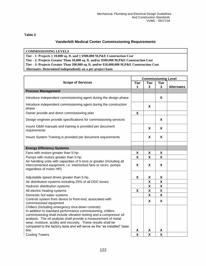
Mechanical, Plumbing and Electrical Design Guidelines And Construction Standards VUMC - 09/17/18
122
Table 2
Vanderbilt Medical Center Commissioning Requirements
COMMISSIONING LEVELS
Tier - 1: Projects ≤ 10,000 sq. ft. and ≤ $500,000 M,P&E Construction Cost
Tier - 2: Projects Greater Than 10,000 sq. ft. and/or $500,000 M,P&E Construction Cost
Tier - 3: Projects Greater Than 200,000 sq. ft. and/or $10,000,000 M,P&E Construction Cost
Alternates: Determined independently on a per project basis
Scope of Services Commissioning Level
Tier 1
Tier 2
Tier 3 Alternates
Process Management
Introduce independent commissioning agent during the design phase X
Introduce independent commissioning agent during the construction phase
X
Owner provide and direct commissioning plan X
Design engineer provide specifications for commissioning services X
Insure O&M manuals and training is provided per document requirements
X X
Insure System Training is provided per document requirements X X
Energy Efficiency Systems
Fans with motors greater than 5-hp. X X X
Pumps with motors greater than 5-hp. X X X
Air handling units with capacities of 5-tons or greater (Including all interconnected equipment, i.e. interlocked fans or recirc. pumps regardless of motor HP).
X X X
Adjustable speed drives greater than 5-hp. X X X
Air distribution systems including 25% of all DDC boxes X X
Hydronic distribution systems X X
All electric heating systems X X X
Domestic hot water systems X X
Controls system from device to front-end, associated with commissioned equipment
X X
Chillers (Including emergency shut-down controls) In addition to standard performance commissioning, chillers commissioning shall include vibration testing and a compressor oil analysis. The oil analysis shall provide a measurement of metal wear, moisture, acidity and viscosity. These results shall be compared to the factory tests and will serve as the “as installed” base line. X X X
Cooling Towers X X X

Mechanical, Plumbing and Electrical Design Guidelines And Construction Standards VUMC - 09/17/18
123
Energy recovery devices X X X
Steam PRV Stations X X
Steam and/or Hot Water Boilers X X X
Glazing X
Opposite Season Testing X X X
Steam, Chilled Water and Domestic Water Meters X X X
Laboratory pressurization controls X X X
Emergency Systems
Emergency shower controls X X X
Automatic Transfer and By-pass/Isolation Switchers X X X
Emergency Generator X X X
Fire Protection - Sprinkler Systems X
Fire Pumps X
Smoke Management Systems X
UPS Systems X
Lightning Protection X X
Other Systems
Electrical Main Switchgear X X
HV/MV Distribution (Hi Potential Test) X
Motor Control Centers X X
Mechanical equipment associated with walk-in coolers X X
Computer Room A/C Units X
Power System Protection X
Exterior Security Lighting Levels X
Special Lighting Levels X
Patient Service Consoles X
Room Status Systems X
Access Control and Alarm Monitoring System X
Radio Paging System X
Public address and program distribution systems X
Fire Alarm and Detection System X
Raised Floor System Grounding X
Raised Floor System Fire Alarm X
X-ray Shielding X
Radio Frequency Shielding X
Elevators X
Pneumatic Tube System X
D.I. Water Systems X
D.I. Water Quality Testing X
Specialty Equipment and Systems X
Indoor Air Quality (O.A. rates, Building pressurization, etc.) X X
Thermal Imaging of Building Envelope for New Buildings X X X
Sound (NC) Level Measurements X

Mechanical, Plumbing and Electrical Design Guidelines And Construction Standards
VUMC - 09/17/18
124
Chapter
24 Mechanical and Plumbing Details
The following standard details shall be utilized on all Vanderbilt University Medical Center projects where applicable. It is acceptable for design engineers to use their own details and own numbering system, as long as the equipment and components are utilized in the same order and fashion as identified in this document. Refer to Appendix A for Mechanical and Plumbing Details.
24.1 Mechanical Details
The following is an index of mechanical details that have been adopted by Vanderbilt University Medical Center:
M01 – Chilled Water Piping at Multiple Coils M02 – Chilled Water Piping at Single Coil M03 – Chilled and Condenser Water Piping at Refrigeration Machine M04 – Piping at Plain Steel Expansion Tank M05 – Piping at Terminal Reheat Box M06 – Hot Water Piping at Convertor M07 – Condensate Cooler M08 – Two Stage Pressure Reducing Station M09 – Piping at Bladder Expansion Tank M10 – Make-Up Water to Cooling Tower M11 – Cooling Tower Chemical Feed Pump M12 – Steam Relief Valve M13 – End Suction Water Pump M14 – In-Line Circulating Pump M15 – Double Suction Water Pump with Y-Strainer M16 - Double Suction Water Pump with Suction Diffuser M17 - A/C Unit Mounted Humidifier M18 – Steam Piping at Convertor M19 – Automatic Steam Control Valve Assembly M20 – Steam Piping at Heating Coil M21 – Steam Piping at Horizontal Multiple Heating Coils M22 – Steam Piping at Heating Coil M23 – Roof Mounted Belted Vent Set Exhaust Fan M24 – Ductwork Connection to Supply Diffuser M25 – Dryer Lint Trap with Screen M26 - Emergency Generator Muffler Exhaust Pipe M27 - Piping at Above Floor Condensate Pump

Mechanical, Plumbing and Electrical Design Guidelines And Construction Standards
VUMC - 09/17/18
125
24.2 Plumbing Details
The following is an index of plumbing details that have been adopted by Vanderbilt University Medical Center:
P01 - Steam Piping at Instantaneous Water Heater P02 – Barrier Free Emergency Shower P03 – Medical Gas Manifold P04 – Deionized Water System P05 – Trap Primer Distribution P06 – Reduced Pressure Backflow Preventer P07 – Duplex Sewage Lift Station P08 – Duplex Sump Pump P09 – Water Meter Detail

Mechanical, Plumbing and Electrical Design Guidelines And Construction Standards
VUMC - 09/17/18
126
Chapter
25 O&M Closeout Documentation
The purpose of this document is to define the required structure for the preparation of Operating and Maintenance documentation for Vanderbilt University Medical Center projects. The date of substantial completion of a project shall not be accepted by Vanderbilt prior to the acceptance and approval of all required O&M documentation.
Closeout documents must be reviewed and accepted for compliance by the Engineer of Record and/or the project commissioning authority prior to final submission to Vanderbilt. These documents must be stamped for approval by the reviewing authority.
The O&M documentation package shall include the following: I. O&M Documentation Table of Contents (Include in all Volumes)II. Emergency Response Information (Include in all Volumes)
III. Operating Manual(s)IV. Maintenance Manual(s) ► Group Sections III – V per CSI
Specification DivisionsV. Test Reports
VI. Construction Documents
I. O&M Documentation Table of ContentsAt the front of each volume provide a master table of contents which includes a directory ofall volumes as well as the contents of that particular volume.
II. Emergency Response InformationEmergency information shall be well organized to allow for quick reference, thus minimizingthe risk of life, property and disruption to the building occupants. Provide a table of contentsidentifying all types of emergencies for which safety information is available.
Example: Emergency Information Table of Contents
Type of Emergency Page No. Fire ## Security ## Floods ## Gas ## Power Failure ## Water Outages ## Elevator ## Heating ## Cooling ## Refrigerant release ##

Mechanical, Plumbing and Electrical Design Guidelines And Construction Standards
VUMC - 09/17/18
127
Chemical spill ## Plumbing overflow ## Medical/Lab Gas Line Break ## Generator ## Telecom/Communications ##
Each section should detail the scope of the emergency, the notification activity, responsibility of facility personnel and the location of pertinent equipment on an 11x17 floor plan drawn to legible scale. Equipment that should be identified on floor plans includes, but is not limited to the following:
Equipment Location/Floor Plan Page No. Fire Hydrants Siamese Connections Fire-fighters’ elevators Main Electrical Equipment Gas Shut-off Valve(s) Fire Hose Cabinets Fire Extinguishers Sprinkler Zone Valves Fire Pump Emergency Generator(s) Heating Plant/Steam Shut-off Valves Chiller Plant/Refrigerant Vents Chiller Emergency Shut-down Controls Domestic Water Service Entrance Medical/Lab Gas Shut-off Valves Motor Control Centers Fire Command Center Fire Fighters Communication Jacks
III. Operating ManualThe purpose for the operating manual is to provide all relevant information needed to convey to Facilities Management personnel the design intent and normal operation parameters of the building and systems. This section should be outlined as follows:
Table of Contents Page No. Section 1: Building Function ## Section 2: Building Description Overview ## Section 3: Operating Standards ## Section 4: Detailed System Description ## Section 5: Start-Up and Shutdown Procedures ## Section 6: Basic Troubleshooting ##
Section 1: Building Function This section should provide a description of the following functional requirements: a) Building occupancy typeb) Tenants functional requirements, including a list of services to be provided in
response to these requirements, levels of these services and timetable of delivery.
Mechanical, Plumbing and Electrical Design Guidelines And Construction Standards VUMC - 09/17/18
128
c) Municipal requirements, including fire department’s response, water use policy, etc. d) Utility information, including names, addresses, phone numbers and e-mail
addresses of utility companies for normal and emergency purposes. Section 2: Building Description Overview
This section provides a brief description of layouts of the building’s floor areas. It should also provide an overview of the building systems using a short text description and simplified single-line schematic drawings. This section should show utility shut-off locations on small scale 11x17 floor plans with a description of what areas of the building are supplied by the utility and by each shut-off device. Section 3: Operating Standards
This section should provide the standards of performance for the building and operating procedures for each system. The operator must understand how to operate each system to achieve the desired standard of performance. These standards include, but are not limited to the following:
A. Space temperature set-points and acceptable range(s) B. Space humidity set-points and acceptable range(s) C. Ventilation rates D. Chilled-water supply temperature E. Hot water temperature schedule F. Domestic water temperature G. Steam pressure H. Manual transfer from normal to emergency power I. Manual parallel and synchronization of generators
Section 4: Detailed System Description
This section should begin with a list of all systems similar to the list in Section 2, followed by a detailed description of each system listed.
This should include a narrative describing the basis of design for each system. The description should identify the areas of the building that the systems serve, the locations of performance checkpoints (i.e. static pressure sensors), the expected performance readings at the design load conditions and, where applicable, at part-load conditions. The systems’ operation during the day, night, and weekend, as well as seasonal start-up and turndown, safety devices and their function, control devices and their function, etc.
The function of the controls for individual systems should be described alongside the description of the system function and an overview of the entire control system should be provided.
The systems included in this section include, but are not limited to the following: A. Fire and Safety B. Heating C. Cooling D. Air Distribution E. Lighting F. Chemical water treatment G. Controls H. Refrigeration I. Plumbing J. Medical Gas

Mechanical, Plumbing and Electrical Design Guidelines And Construction Standards VUMC - 09/17/18
129
K. Pneumatic Tube System Section 5: Start-Up and Shutdown Procedures This section should list normal, break-in, emergency and seasonal start-up and shutdown procedures. Section 6: Troubleshooting This section should include basic troubleshooting procedures. These procedures may include simple questionnaires or detailed diagnostics, depending on the degree of system complexity.
IV. Maintenance Manual
The maintenance information of each product or system should be preceded by the name, address, telephone number and e-mail address of the installer or subcontractor and a local source for parts and replacement equipment. The following information shall be provided where applicable for all products or equipment:
A. Equipment and/or products shall be identified by names and/or symbols as set forth in the Contract Documents.
B. Provide specification information consisting of drawings and a written description. C. Description of the function of equipment, pre-start-up procedures, functional
parameters (input, output) at the design load and at part loads, and performance verification procedures.
D. Recommended maintenance procedures and their recommended frequency. E. Provide performance curves, engineering data and tests where appropriate. F. Provide a complete list of parts along with illustrations, part numbers, assembly
drawings and diagrams required for maintenance. G. Original purchase order number, date of purchase, and warranty information. H. Installation information I. Predicted life of parts subject to wear. J. Lists of items recommended to be stocked as spare parts. K. List of lubricants required
V. Test Reports The purpose of this section is to identify the performance targets, testing procedures and document the results of testing. This section should be structured in three sub-sections as follows: Section 1. Performance Targets This section should document all the specified performance targets for the building, its systems and equipment. This should include but not be limited to the following requirements:
➢ Temperature and humidity control reliability ➢ Ventilation ➢ Illumination ➢ Medical gas certification ➢ Piping pressure testing ➢ Roof water flood testing ➢ Duct pressure testing

Mechanical, Plumbing and Electrical Design Guidelines And Construction Standards VUMC - 09/17/18
130
➢ Chiller efficiency and capacity testing ➢ Vibration isolation testing ➢ Motor Control Centers ➢ Switchgear ➢ Emergency Generators ➢ Radiation Shielding ➢ Fire Pump Flow Testing
Section 2. Testing Procedures This section should contain testing procedures for all tests that were performed. This information should be located in the specifications, from which it should be copied and shown here for convenience. Section 3. Test Results This part of the document should, for each system and/or piece of equipment as applicable, catalog in chronological order the results of the tests performed in the factory and on site. It should also allow for inclusion of additional test results performed throughout the service life of the facility.
VI. Construction Documents This segment consists of six (6) elements containing the following documents: Section 1: Record Drawings Section 2: Final specifications with all addenda Section 3: Approved product data and shop drawings Section 4: Warranty Certificates Section 5: Inspection Certificates Section 6: Final Commissioning Report
Mechanical, Plumbing and Electrical Design Guidelines And Construction Standards VUMC - 09/17/18
131
Appendix
A Mechanical and Plumbing Details


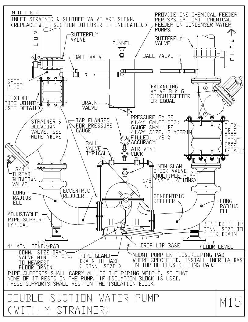


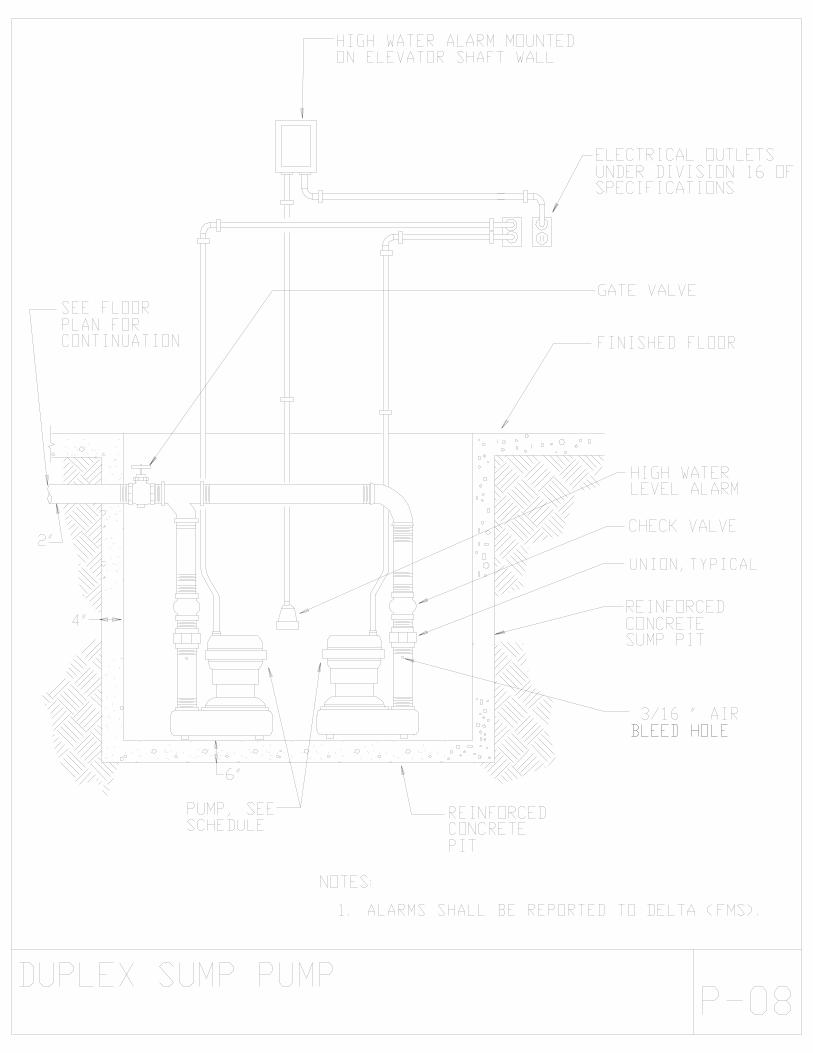


Mechanical, Plumbing and Electrical Design Guidelines And Construction Standards VUMC - 09/17/18
Appendix
B BSL-3 Laboratory Design Schematic
