vamp 259 - s; e
TRANSCRIPT

Protection
vZ3
Z1
Z2
Z4
Z5
X
R
01
VAMP 259Line manager for distance and line differential protection
MAIN CHARACTERISTICS
• �Medium voltage/sub transmission line differential protection (87L)
• Distance protection (including full scheme) with 30 independent distance elements for 6 measuring systems (21/21E)
• Pilot channel communication functionality for various protection schemes (85)
• Complete set of time and instantaneous overcurrent, overvoltage, undervoltage, and frequency protection functions
• Sensitive earth fault protection functions which are suitable for compensated, isolated and solidly grounded networks
• Programmable protection stages
• Auto-reclose function
• Synchrocheck function
• Switch-onto-fault(SOTF) functionality
• Digital input support for Trip Circuit Supervision
• Selectable nominal DI activation voltage
• Frequency stage df/dt (ROCOF)
• Fault value, alarm led display, event buffer, blackout data and disturbance recording storage in non volatile memory
• Native solution for IEC61850 communication with support for GOOSE messages
• Removable / interchangeable communication modules for connecting the relay to various system communication solutions and medias
The VAMP 259 line manager is used for applications where combined protection, remote and local control, measurement, power quality, alarming and status indication functions are needed. The manager is suitable for full-scheme distance protection and it incorporates line differental functions usually required for the protection of subtransmission cables and overhead lines.

VAMP 259Protection 02
The distance protection function calculates the impedance Z = U/I for each of the distance elements. If impedance is inside the tripping zone (normally presented in R-X plane), the distance function operates. For short circuit protection there are 15 independent elements and earth fault protection. The distance protection function calculates impedances in each of the fault loops continuously thus giving the distance protection high precision and accuracy for demanding sub-transmission applications.
The distance protection’s zones implement polygonal characteristics. Additionally the function supports load blocking area (i.e. load encroachment area) settings which are possible to enable for each zone individually.
VAMP 259 distance protection is applicable for power systems where the grounding (earthing) star point can be solid or low resistance grounded. Resonant-earthed via Petersen coil or isolated can be protected with sensitive directional earth fault protection.
The distance protection tripping can operate with or without the use of tele protection schemes. For example, when POTT (Permissive Overreaching zone Transfer Trip) or PUTT (Permissive Underreaching zone Transfer Trip) is required it can be achieved via any DI/DO signals or pilot channel communication (85). At least one DI/DO pair is required per direction.
Line distance protection
Z
Rset
Xset
Trippingzone
Line
Line
Zone 1
Zone 1
Zone 2
Zone 2
Zone 3
Zone 3
X
R
Zone 4
Zone 4
Zone 5
Zone 5
X
Load anglesetting
R
TYPICAL APPLICATION
An example of a tripping zone presented in RX-plane
In this example zones 1... 3 are forward, zone 4 is in reverse direction and zone 5 is non-directional. An example of the distance protection load blocking area
setting.
Distance protection application polygonal characteristics
VAMP 259 21,85,87L25,27,59,7967/67N50/51,50/51N
VAMP 259 21,85,8725,27,59,7967/67N50/51,50/51N
Pilot channel communication
Cable or over head line
VAMP 259Protection 03
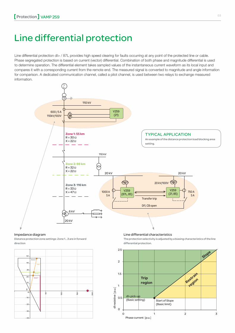
Line differential protection dI> / 87L provides high speed clearing for faults occurring at any point of the protected line or cable. Phase segregated protection is based on current (vector) differential. Combination of both phase and magnitude differential is used to determine operation. The differential element takes sampled values of the instantaneous current waveform as its local input and compares it with a corresponding current from the remote end. The measured signal is converted to magnitude and angle information for comparison. A dedicated communication channel, called a pilot channel, is used between two relays to exchange measured information.
Line differential protection
0
0
Line
Zone 1
Zone 2
Zone 3
- 10
10
- 20
20
30
40
50
50
100
150
200
- 30
- 40
Trip region
dl> pick-up(Basic setting)
Phase current p.u.
dl re
sist
ive
p.u
.
Start of Slope(Basic limit)
00 1 2 3
0.5
1
1.5
2.5
2Slope
Restrain
region
Impedance diagram Line differential characteristicsDistance protection zone settings: Zone 1...3 are in forward direction
The protection selectivity is adjusted by a biasing characteristics of the line differential protection.
TYPICAL APPLICATIONAn example of the distance protection load blocking area setting.
Zone 1: 55 kmR = 30 X = 22
Zone 2: 66 kmR = 32 X = 22
6 kV
20 kV 20 kV
110 kV
110 kV
600 / 5 A110kV/100V
20 kV
Zone 3: 116 kmR = 33 X = 47 1000 A
5 A 750 A
5 A
20 kV/100V
Transfer trip
Dl1, CB open
V259(87L, 85)
V259(21, 85)
V259(21)

VAMP 259Protection 04
When time-grading or blocking based protection coordination principles are used, traditional protection systems may not provide fast enough protection of substation faults. Further, high- impedance type faults may cause prolonged operation times of earth-fault relays, leading to significant release of arc energy. These facts pose a considerable risk to human beings and economical assets. By applying a modern, high- speed arc flash protection system, the damage may be considerably reduced. Such an arc flash protection system is an optional feature that can be incorporated in all current measuring VAMP relays.
VAMP relays measure fault current and with the optional arc protection, also measure light via arc sensor channels which monitor the whole switchgear. Should an arcing fault occur in the switchgear the arc flash protection system provides extremely fast tripping of the circuit breaker. The fault will be prevented from spreading and quickly isolated, which may save human lives and valuable economical assets.
Arc flash protection
Communication
Traditional protection relay systems do not provide fast enough protection in arc-fault situations.
Maintenance terminalSC A DA , DC S or SA system
Ethernet, RS 485 or fibre
* IEC 61850 also- over fiber optic - over dual port
interface
IEC 60870-5-101, IEC 60870-5-103, Modbus RTU, Modbus TCP, Profibus, SPA, DNP 3.0, DNP TCP, IEC 61850 * Device Net or Ethernet/IP
• Control and status of the process• Events• Measurements• Fault location• Time synchronising using GPS
• Relay settings, configuration• Fault and disturbance analysis• Power quality monitoring• Primary equipment condition monitoring• Time synchronising using GPS
Physical media:• RS485• RS232• Fibre optic• Ethernet
The IEC 61850 data model, data-sets, report control blocks and GOOSE communication are configured according to the requirements of the system configuration. Vampset is also used to produce ICD files, which may be needed for the substation RTU configuration.
The IEC 61850 solution is a native implementation which means that the IEC 61850 functionality is embedded in the software. Software requires only the main CPU of the relay – no additional processor or gateway module is needed.
The Vamp 259 line manager can be equipped with an in-built Ethernet interface which can be used for either ModbusTCP, DNP 3.0 over TCP and IEC 61850 communication.
The IEC 61850 protocol can be used to read or write static data or to receive events sent spontaneously from the relay. In addition, the interface allows peer-to-peer communication between the relays - this is GOOSE communication. The IEC 61850 interface is configured with familiar, user-friendly Vampset software.
VAMP 259Protection 05
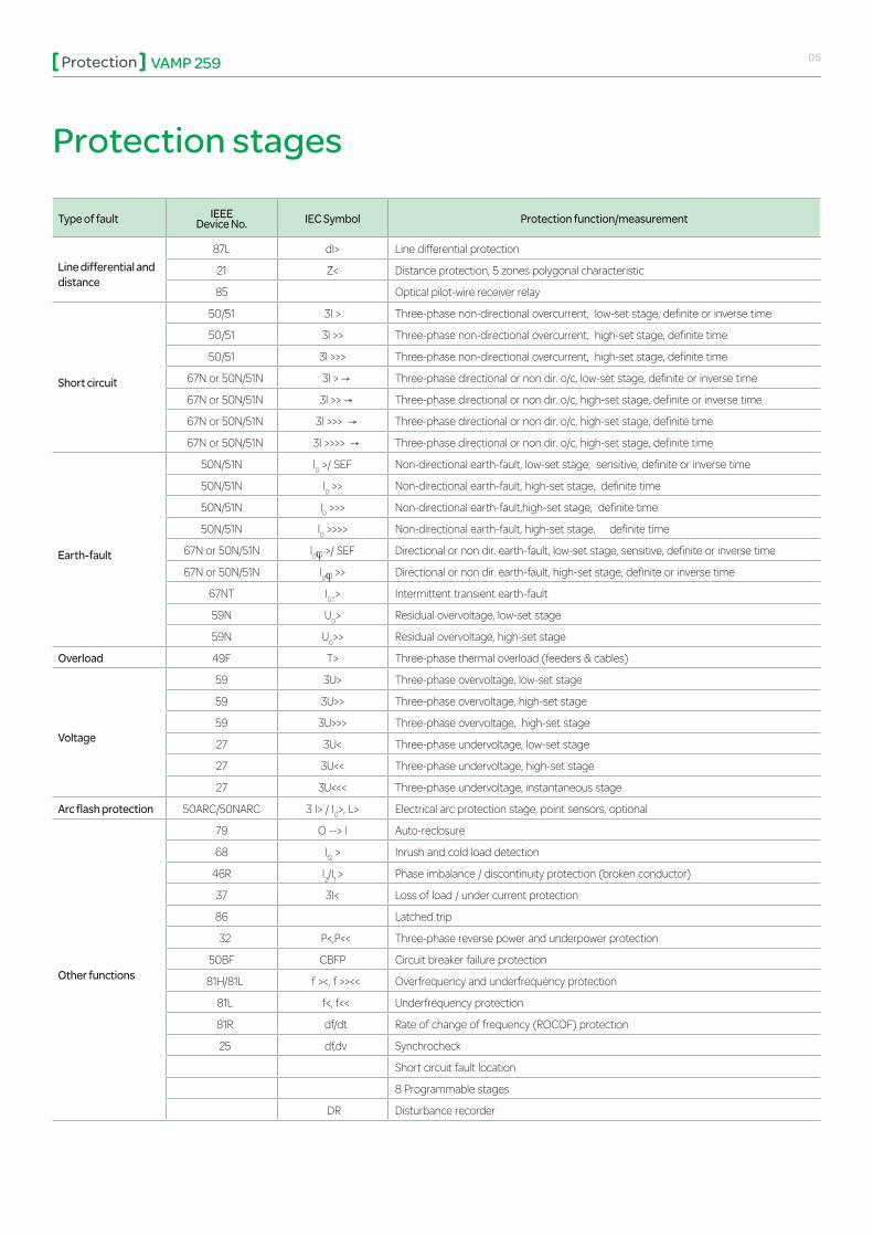
Type of fault IEEE Device No. IEC Symbol Protection function/measurement
Line differential and distance
87L dI> Line differential protection
21 Z< Distance protection, 5 zones polygonal characteristic
85 Optical pilot-wire receiver relay
Short circuit
50/51 3I > Three-phase non-directional overcurrent, low-set stage, definite or inverse time
50/51 3l >> Three-phase non-directional overcurrent, high-set stage, definite time
50/51 3l >>> Three-phase non-directional overcurrent, high-set stage, definite time
67N or 50N/51N 3l > Three-phase directional or non dir. o/c, low-set stage, definite or inverse time
67N or 50N/51N 3l >> Three-phase directional or non dir. o/c, high-set stage, definite or inverse time
67N or 50N/51N 3I >>> Three-phase directional or non dir. o/c, high-set stage, definite time
67N or 50N/51N 3I >>>> Three-phase directional or non dir. o/c, high-set stage, definite time
Earth-fault
50N/51N l0 >/ SEF Non-directional earth-fault, low-set stage, sensitive, definite or inverse time
50N/51N l0 >> Non-directional earth-fault, high-set stage, definite time
50N/51N l0 >>> Non-directional earth-fault,high-set stage, definite time
50N/51N l0 >>>> Non-directional earth-fault, high-set stage, definite time
67N or 50N/51N l0 >/ SEF Directional or non dir. earth-fault, low-set stage, sensitive, definite or inverse time
67N or 50N/51N l0 >> Directional or non dir. earth-fault, high-set stage, definite or inverse time
67NT I0T> Intermittent transient earth-fault
59N U0> Residual overvoltage, low-set stage
59N U0>> Residual overvoltage, high-set stage
Overload 49F T> Three-phase thermal overload (feeders & cables)
Voltage
59 3U> Three-phase overvoltage, low-set stage
59 3U>> Three-phase overvoltage, high-set stage
59 3U>>> Three-phase overvoltage, high-set stage
27 3U< Three-phase undervoltage, low-set stage
27 3U<< Three-phase undervoltage, high-set stage
27 3U<<< Three-phase undervoltage, instantaneous stage
Arc flash protection 50ARC/50NARC 3 I> / I0>, L> Electrical arc protection stage, point sensors, optional
Other functions
79 O --> I Auto-reclosure
68 lf2 > Inrush and cold load detection
46R I2/I1 > Phase imbalance / discontinuity protection (broken conductor)
37 3I< Loss of load / under current protection
86 Latched trip
32 P<,P<< Three-phase reverse power and underpower protection
50BF CBFP Circuit breaker failure protection
81H/81L f ><, f >><< Overfrequency and underfrequency protection
81L f<, f<< Underfrequency protection
81R df/dt Rate of change of frequency (ROCOF) protection
25 df,dv Synchrocheck
Short circuit fault location
8 Programmable stages
DR Disturbance recorder
Protection stages
VAMP 259Protection 06
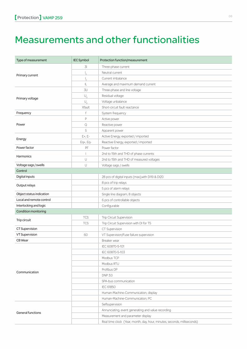
Type of measurement IEC Symbol Protection function/measurement
Primary current
3I Three-phase current
l0 Neutral current
I2 Current imbalance
IL Average and maximum demand current
Primary voltage
3U Three-phase and line voltage
U0 Residual voltage
U2 Voltage unbalance
Xfault Short-circuit fault reactanceFrequency f System frequency
PowerP Active power
Q Reactive power
S Apparent power
EnergyE+, E- Active Energy, exported / imported
Eq+, Eq- Reactive Energy, exported / importedPower factor PF Power factor
HarmonicsI 2nd to 15th and THD of phase currents
U 2nd to 15th and THD of measured voltagesVoltage sags / swells U Voltage sags / swellsControlDigital inputs 28 pcs of digital inputs (max),with DI19 & DI20
Output relays8 pcs of trip relays
5 pcs of alarm relaysObject status indication Single line diagram, 8 objectsLocal and remote control 6 pcs of controllable objectsInterlocking and logic ConfigurableCondition monitoring
Trip circuitTCS Trip Circuit Supervision
TCS Trip Circuit Supervision with DI for T5CT Supervision CT SupervisionVT Supervision 60 VT Supervision/Fuse failure supervisionCB Wear Breaker wear
Communication
IEC 60870-5-101
IEC 60870-5-103
Modbus TCP
Modbus RTU
Profibus DP
DNP 3.0
SPA-bus communication
IEC 61850
Human-Machine-Communication, display
Human-Machine-Communication, PC
General functions
Selfsupervision
Annunciating, event generating and value recording
Measurement and parameter display
Real time clock (Year, month, day, hour, minutes, seconds, milliseconds)
Measurements and other functionalities

VAMP 259Protection 07
U12 UL1
Connection diagrams
ULLY
VA MP 255
L1
L2
L3
0
1
-
-+
+
+
X8:1 0
X8:1 1
X8:1 2
~
X1 :1
X1 :2
X1 :3X1 :4
X1 :5
X1 :6
X1 :7X1 :8
X1 :9
X1 :1 2
X1 :1 3
X1 :1 4
X1 :1 7X1 :1 8
X1 :1 0
X1 :1 1
X3:1 7
X3:1 8
Protection functions
Option Block
IL 1
IL 2
IL 3
I01
U1
U2
U3
Ulxy
T1 X3:1 4X3:1 4
X3:1 5
T2 X3:1 2
X3:1 3
T3 X7:1 7
X7:1 8
T4 X7:1 5
X7:1 6
IF X2:9
X2:1 0
X2:1 1
T5 X8:1 9
X8:20
A 1 X3:9
X3:1 1
X3:1 0
X8:1 7
X8:1 8
T6
X8:1 5
X8:1 6
T7
X8:1 3
X8:1 4
T8
A 2 X2:7
X2:8
A 3 X2:5
X2:6
A 4 X2:3
X2:4
A 5 X2:1
X2:2
CommunicationOption 1
CommunicationOption 2
Front
Remote port
Local port
Extension port
X1 0
X9
+48V
X6:2
X6:3
X6:4
X6:5
X6:6
X6:7
X8:1X8:2X8:3
X8:4
X8:5
X8:6X8:7X8:8X8:9X8:1 0
X8:1 1
X8:1 2
Comm
X6:1
X3:2
X3:3
X3:4
X3:5
X3:6
X3:7
X3:1DI
DI1DI2DI3DI4DI5
DI6
X7:2
X7:3
X7:4
X7:5
X7:6
X7:7
X7:1DI
DI8DI9DI1 0DI1 1DI1 2
DI7
Comm
X7:9
X7:1 0
X7:1 1
X7:1 2
X7:1 3
X7:1 4
X7:8DI
DI1 4DI1 5DI1 6DI1 7DI1 8
DI1 3
DI
Comm
Comm
Comm
Comm
DI1 8
DI21DI22
DI23DI24
DI25DI26
DI27DI28
C BFP
50BF
I >f2
68
3I<
37
3I>
3I> >
3I> > >
50 / 51
3I> > >
3I> >
3I>
3I> > > >
67
I / I >2 1
46 R
A rc I>
50ARC
T >
49
I > >2
47
I >2
46
I >st
48
N>
66
Autoreclose
79
I >0
67N
I > >0
U<
U< <
U< < <
27
U>
U> >
U> > >
59
I > ,0 I >02
I >> ,0 I > >02
50N/51N
U >0
U > >0
5
U0
59N
81H/81L
f > <
f > > < <
81L
f <
f < <
5ONARC
A rc I >01
A rc I >02
U =f
25
32
P <
P < <
d f/ d t
81R
Z<
21
I >0T
67NT
Ze <
21 N
1 A (C)0.2 A (D)
VAMP 259-4C7
Blocking andoutput matrix
Autoreclosermatrix
When the voltage transformer is connected to transform the phase to ground voltage, the voltage measuring mode shall be 1LN
Should the voltage transformer connection be phase to phase the voltage measuring mode is selected 1LL

VAMP 259Protection 08
Dimensional drawings
OK
Power
Error
Com
Alarm
Trip
ABC
VAMP 200 series
1.0-100.04 - 0.39
193
7.60
139
5.47
24
5
PANEL MOUNTING VAMP 200 SERIES
3
PROJECTION MOUNTING VAMP 200 SERIES
41
1.0 -100.04 - 0.39
271.06
1817.13
281.10
B A
210.83
>
2a2b
1375.39
Panel mounting
mmin
2088.19
1556.10
1907.48
20
0.79
Projection B Fixing bracket
VYX076 40 mm /1.57’’ 169 mm/ 6.65’’ Standard for 200 series
VYX077 60 mm /2.36’’ 149 mm/ 5.87’’ Standard for 200 series
VYX233 100 mm / 3.94’’ 109 mm/4.29’’ 2 x VYX199 needed
A
OK
Power
Error
Com
Alarm
Trip
ABC
OK
Power
Error
Com
Alarm
Trip
ABC
OKOK
VAMP 200 series
Power
Error
Com
Alarm
Trip
A
B
C
VAMP 200 series
VAMP 200 series
Projection mounting

VAMP 259Protection 09
Order Codes
V 259 -
Nominal phase current (A) / nominal DI7-28 activation voltage4 = Standard 24 Vdc
5 = 1A / 5 A / 24 V (UL)
6 = 1A / 5 A / 110 V
7 = 1A / 5 A / 220 V
Nominal earth-fault current Io1 [A]
B = 5 A
C = 1 A
D = 0.2 A
Additional I/O (X8 terminal)
6 = None
7 = 8 standard inputs, 4 TCS Hybrid inputs / outputs
8 = 10 outputs
9 = 8 standard inputs and 4 outputs
Supply voltage [V]
A = 40.. 265 Vac/dc
B = 18.. 36 Vdc
C = 40.. 265 Vac/dc + ARC Protection
D = 18.. 36 Vdc + ARC Protection
E = 40.. 265 Vac/dc + DI19, DI20 Optional
F = 18.. 36 Vdc + DI19, DI20 Optional
Optional hardware (communication port 1)
A = TTL/RS-232
B = Plastic/Plastic serial fibre interface (VCM fibre PP)
C = N/A
D = RS 485 interface (4-wire, VCM 485-4)
E = Glass/Glass serial fibre interface (VCM fibre GG)
F = Rx Plastic/Tx Glass serial fibre interface (VCM fibre PG)
G = Rx Glass/Tx Plastic serial fibre interface (VCM fibre GP)
I = RS 232 with RJ-45 connector (VCM 232)
M = ST 100Mbps ethernet fibre interface inc. IEC 61850
N = RTD interface (Glass fibre, VCM RTD)
Optional hardware (communication port 2)
A = None
C = RS 232 with RJ-45 connector (VCM 232)
D = RS-485 interface (2-wire, VCM 485-2)
L = RJ-45 10Mbps ethernet interface (1
M = RJ-45 10Mbps ethernet interface inc. IEC 61850 (1
N = RTD interface (Glass fibre, VCM RTD)
Ingress protection rating
= IP30 (default)
I = IP54 (option)
4
Note:
(1 NOT possible to order in combination with the following optional communication module 1: (M) ST 100 Mbps ethernet fibre interface with IEC 61850

VAMP 259Protection 10
Order code Explanation Note
VEA3CGi Ethernet adapter
VPA3CG Profibus DP fieldbus option board
VSE001PP Fiber optic Interface Module (plastic - plastic)
VSE002 RS485 Interface Module
VIO 12 AA RTD Module, 12pcs RTD inputs, Optical Tx Communication (24-230 V ac/dc)
VIO 12 AB RTD Module, 12pcs RTD inputs, RS 485 Communication (24-230 V ac/dc)
VIO 12 ACRTD and mA output/input module, 12pcs RTD inputs, PTC, mA inputs/outputs,
RS232, RS485 and Optical Tx/Rx Communication (24 Vdc)
VIO 12 ADRTD/mA Module, 12pcs RTD inputs, PTC, mA inputs/outputs,
RS232, RS485 and Optical Tx/Rx Communication (48-230 V ac/dc)
VX003-3 RS232 programming cable (Vampset, VEA 3CGi) Cable length 3 m
3P025 USB to RS232 Adapter
VX004-M3 TTL/RS232 converter cable (PLC, VEA 3CGi) Cable length 3 m
VX007-F3 TTL/RS232 converter cable (VPA 3CG) Cable length 3 m
VX048 RS232 (COM1=A) converter cable for MOXA TCF-90 (remote port) Cable length 3 m
VX062 RS232 (COM1=A) converter cable for MOXA TCF-142-S-ST Cable length 3 m
VX055 RJ45 (COM1=I or COM2=C) converter cable for MOXA TCF-90 (old LdI>>>) Cable length 3 m
VX056 RJ45 (COM1=I or COM2=C) converter cable for MOXA TCF-142-S-ST (old LdI>>>) Cable length 3 m
VX065 RJ45 (COM1=I or COM2=C) converter cable for MOXA TCF-90 (new LdI>/LdI>>) Cable length 3 m
VX066 RJ45 (COM1=I or COM2=C) converter cable for MOXA TCF-142-S-ST (new LdI>/LdI>>) Cable length 3 m
3P014 MOXA TCF-90
3P022 MOXA TCF-142-S-ST
3P032 WESTERMO ODW-720-F1 (Base module)
3P033 WESTERMO SLC20 (1310 nm) Max. distance 20 km
3P034 WESTERMO SLC40 (1310 nm) Max. Distance 40 km
3P035 WESTERMO SLC80 (1550 nm) Max. distance 80 km
3P036 WESTERMO SLC120 (1550 nm) Max. distance 120 km
VX063 RS232 (COM1=A) converter cable for WESTERMO ODW-720-F1 (remote port) 0
VX064 RJ45 (COM1=I or COM2=C) converter cable for WESTERMO ODW-720-F1 Cable length 3 m
VA 1 DA-6 Arc Sensor Cable length 6 m
VAM 16D External LED module Disables rear local communication
VYX076 Raising Frame for 200-series Height 40 mm
VYX077 Raising Frame for 200-series Height 60 mm
VYX233 Raising Frame for 200-series Height 100 mm
V200WAF V200 wall assembly frame
ACCESSORIES
Available option-cards possible to be ordered separately:
Order code Explanation
VCM 485-4 RS 485 interface (4 wire)
VCM 485-2 RS 485 interface (2 wire)
VCM FIBRE PP Serial fibre interface (Plastic/Plastic)
VCM FIBRE GG Serial fibre interface (Glass/Glass)
VCM FIBRE PG Serial fibre interface (Plastic/Glass)
VCM FIBRE GP Serial fibre interface (Glass/Plastic)
VCM 232 RS 232 with RJ45 connector
VCM RTD RTD interface (Glass fibre)
VCM TTL TTL/RS-232 interface

VAMP 259Protection 11
Technical Data, Tests and Environmental Conditions
Rated phase current 5 A (configurable for CT secondaries 1 – 10 A)
Current measuring range 0…250 A
Thermal withstand 20 A (continuously)
100 A (for 10 s), 500 A (for 1 s)
Burden < 0.2 VA
Rated residual current (optional) 5A (configurable for CT secondaries 1 – 10 A)
Current measuring range 0…50 A
Thermal withstand 20 A (continuously)
100 A (for 10 s), 500 A (for 1 s)
Burden < 0.2 VA
Rated residual current 1 A (configurable for CT secondaries 0.1 – 10.0 A)
Current measuring range 0…10 A
Thermal withstand4 A (continuously)
20 A (for 10 s), 100 A (for 1 s)
Burden < 0.1 VA
Rated residual current (optional) 0.2 A (configurable for CT secondaries 0.1-10.0 A)
Current measuring range 0…2 A
Thermal withstand 0.8 A (continuously)
4 A (for 10 s), 20 A (for 1 s)
Burden < 0.1 VA
Rated voltage Un 100 V (configurable for VT secondaries 50-120 V)
Voltage measuring range 0 – 160 V (100 V/110 V)
Continuous voltage withstand 250 V
Burden < 0.5V A
Rated frequency fn 45 – 65 Hz
Frequency measuring range 16 – 75 Hz
Terminal block Solid or stranded wire
Maximum wire dimension 4 mm2 (10-12 AWG)
Measuring circuitry
Type A (standard) Type B (option)
Rated voltage Uaux
40 - 265 V ac/dc 18...36 V dc
110/120/220/240 V 24 V dc
48/60/110/125/220 V dc
Power consumption < 7 W (normal conditions)
< 15 W (output relays activated)
Max. permitted interruption time < 50 ms (110 V dc)
Terminal block: Phoenix MVSTBW or equivalent
Maximum wire dimension 2.5 mm2 (13-14 AWG) :
Auxiliary voltage
PackageDimensions (W x H x D) 215 x 160 x 275 mm
Weight (Terminal, Package and Manual )
5.2 kg
VAMP 259Protection 12
DEVICE TRACK RECORD
• Schneider Electric’s VAMP Range specializes in arc flash protection relays for power systems.
• Schneider Electric VAMP’s arc flash fault protection functionality enhances the safety of both people and property and has made Schneider Electric VAMP a pioneer in the field of arc flash protection with more than 10.000 VAMP arc flash systems and units with over 150.000 arc detecting sensors in service worldwide.
• Schneider Electric VAMP products meet the latest international standards and regulations.
08-2013 © 2
013
Sch
neid
er E
lect
ric In
dust
ries
SA
S -
All
right
s re
serv
ed
As standards, specifications and designs change from time to time, please ask for confirmation of the information given in this publication.
Design: Schneider Electric Industries SAS - SonovisionPhotos: Schneider Electric Industries SAS Printed in France
NRJED112418EN
This document has been printed on recycled paper.
Schneider Electric Industries SAS
35, rue Joseph Monier CS 30323 F - 92506 Rueil Malmaison Cedex (France)Tel.: +33 (0) 1 41 29 70 00RCS Nanterre 954 503 439 Capital social 896 313 776 €www.schneider-electric.com
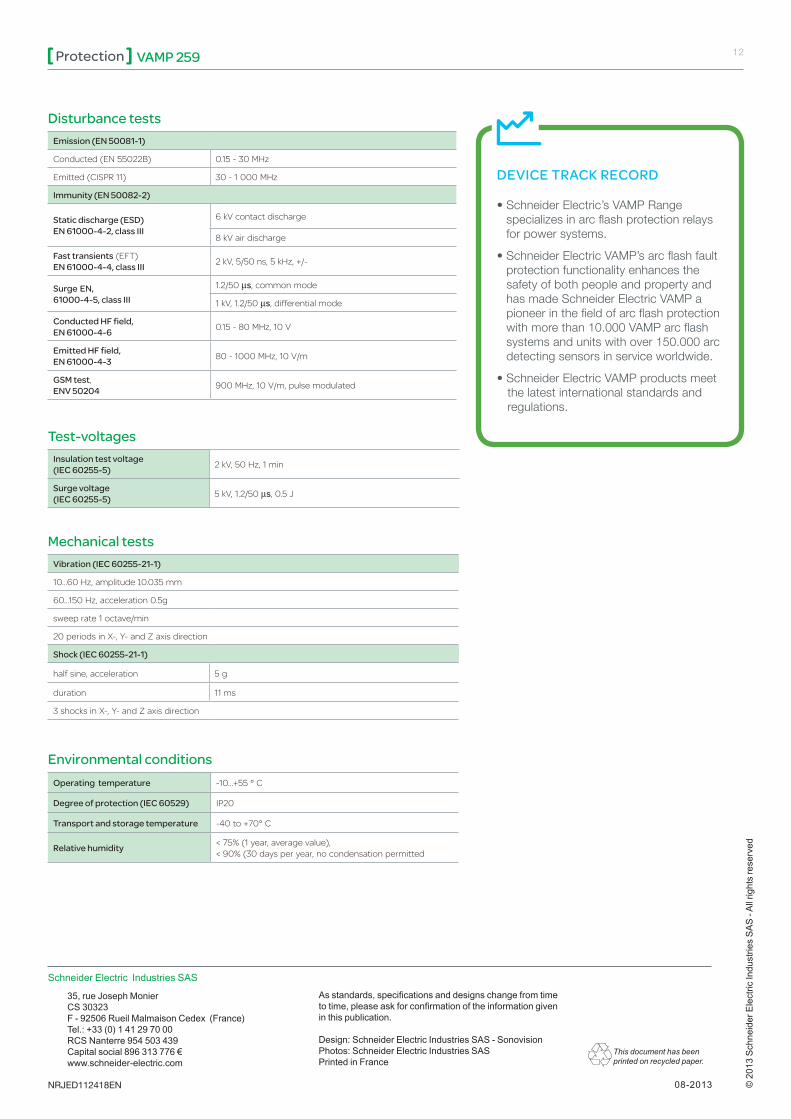
Emission (EN 50081-1)
Conducted (EN 55022B) 0.15 - 30 MHz
Emitted (CISPR 11) 30 - 1 000 MHz
Immunity (EN 50082-2)
Static discharge (ESD) EN 61000-4-2, class III
6 kV contact discharge
8 kV air discharge
Fast transients (EFT) EN 61000-4-4, class III 2 kV, 5/50 ns, 5 kHz, +/-
Surge EN, 61000-4-5, class III
1.2/50 ms, common mode
1 kV, 1.2/50 ms, differential mode
Conducted HF field, EN 61000-4-6 0.15 - 80 MHz, 10 V
Emitted HF field, EN 61000-4-3 80 - 1000 MHz, 10 V/m
GSM test,ENV 50204 900 MHz, 10 V/m, pulse modulated
Insulation test voltage(IEC 60255-5) 2 kV, 50 Hz, 1 min
Surge voltage (IEC 60255-5) 5 kV, 1.2/50 ms, 0.5 J
Disturbance tests
Test-voltages
Vibration (IEC 60255-21-1)
10...60 Hz, amplitude ±0.035 mm
60...150 Hz, acceleration 0.5g
sweep rate 1 octave/min
20 periods in X-, Y- and Z axis direction
Shock (IEC 60255-21-1)
half sine, acceleration 5 g
duration 11 ms
3 shocks in X-, Y- and Z axis direction
Mechanical tests
Operating temperature -10...+55 ° C
Degree of protection (IEC 60529) IP20
Transport and storage temperature -40 to +70° C
Relative humidity < 75% (1 year, average value), < 90% (30 days per year, no condensation permitted
Environmental conditions