valves 101
TRANSCRIPT
Valves 101Identifying Valve Standards and Engineered Valve Solutions
Gobind KhianiAIMs Manager
APPEGA, Calgary-Alberta, Nov 30th 2011
DISCLAIMER
-The content of this presentation are intended for educational purposes only and do not
replace independent professional judgment. They do not constitute advice and should not be relied upon in making or refraining from
making) any decision.
- Statement of fact and opinions expressed are those of the speaker alone and are not the opinion or position of his employers, past or present, nor those of the professional bodies
and committees in which he participates.
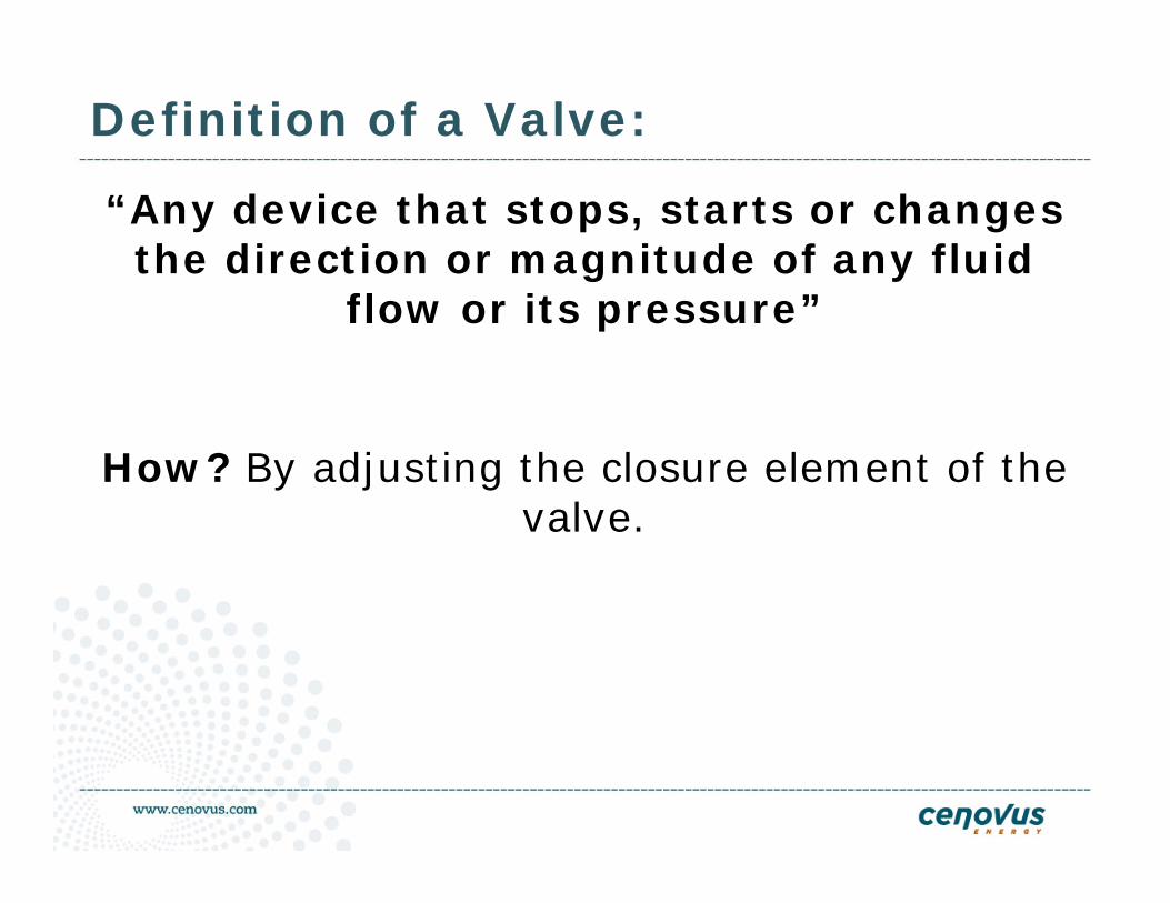
Definition of a Valve:
“Any device that stops, starts or changes the direction or magnitude of any fluid
flow or its pressure”
How? By adjusting the closure element of the valve.
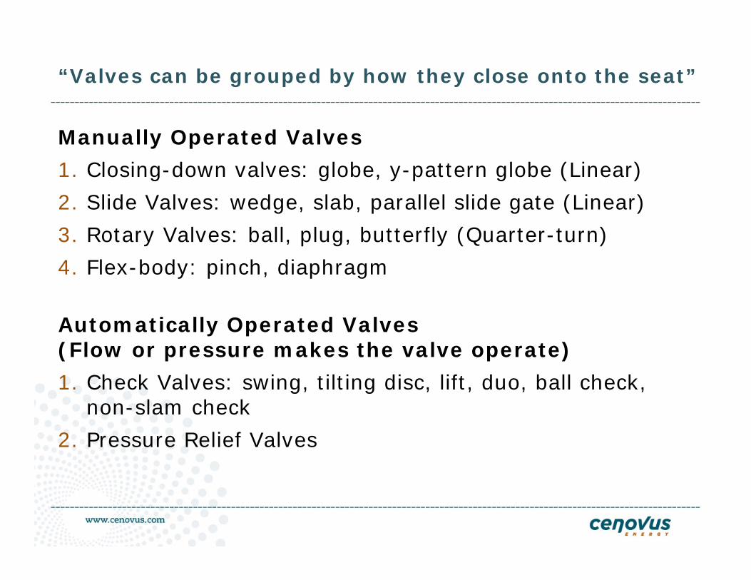
“Valves can be grouped by how they close onto the seat”
Manually Operated Valves
1. Closing-down valves: globe, y-pattern globe (Linear)
2. Slide Valves: wedge, slab, parallel slide gate (Linear)
3. Rotary Valves: ball, plug, butterfly (Quarter-turn)
4. Flex-body: pinch, diaphragm
Automatically Operated Valves (Flow or pressure makes the valve operate)
1. Check Valves: swing, tilting disc, lift, duo, ball check, non-slam check
2. Pressure Relief Valves
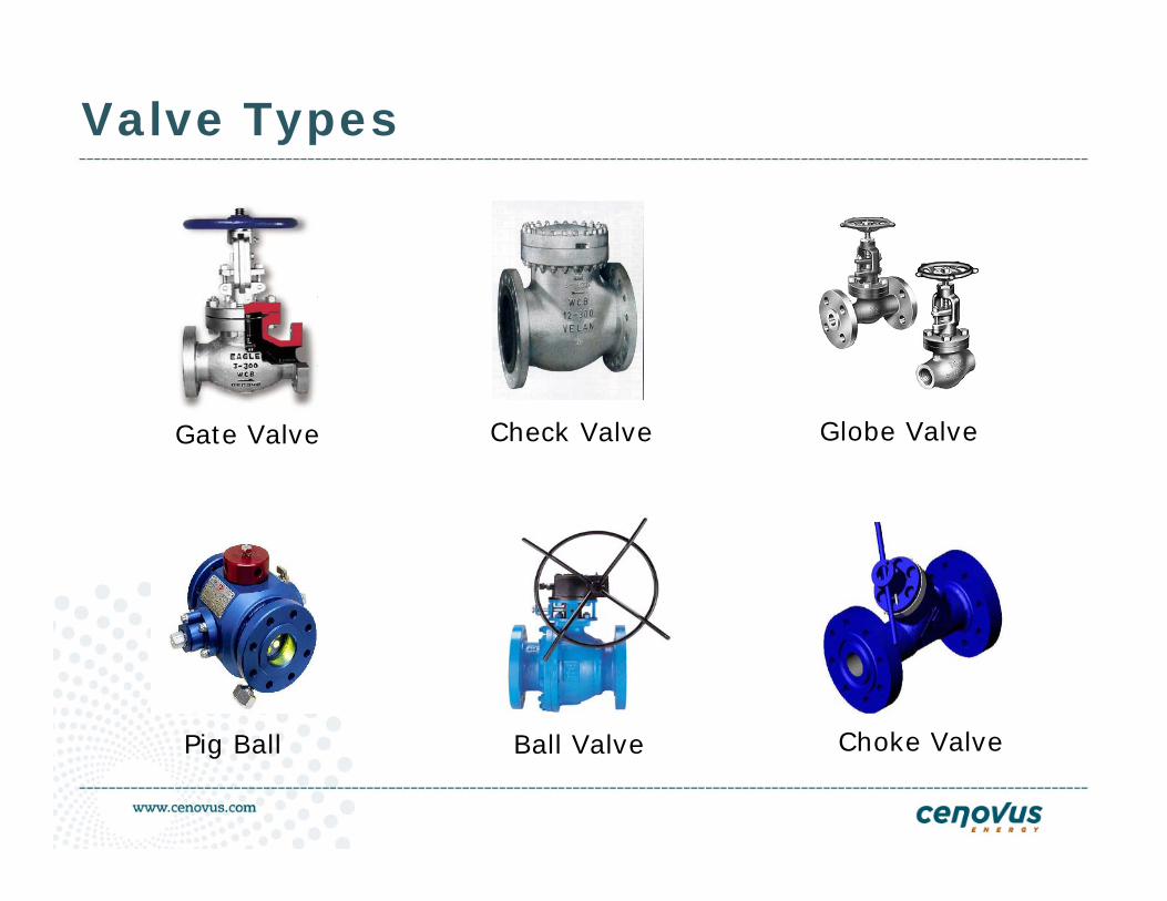
Valve Types
Check ValveGate Valve Globe Valve
Pig Ball Ball Valve Choke Valve
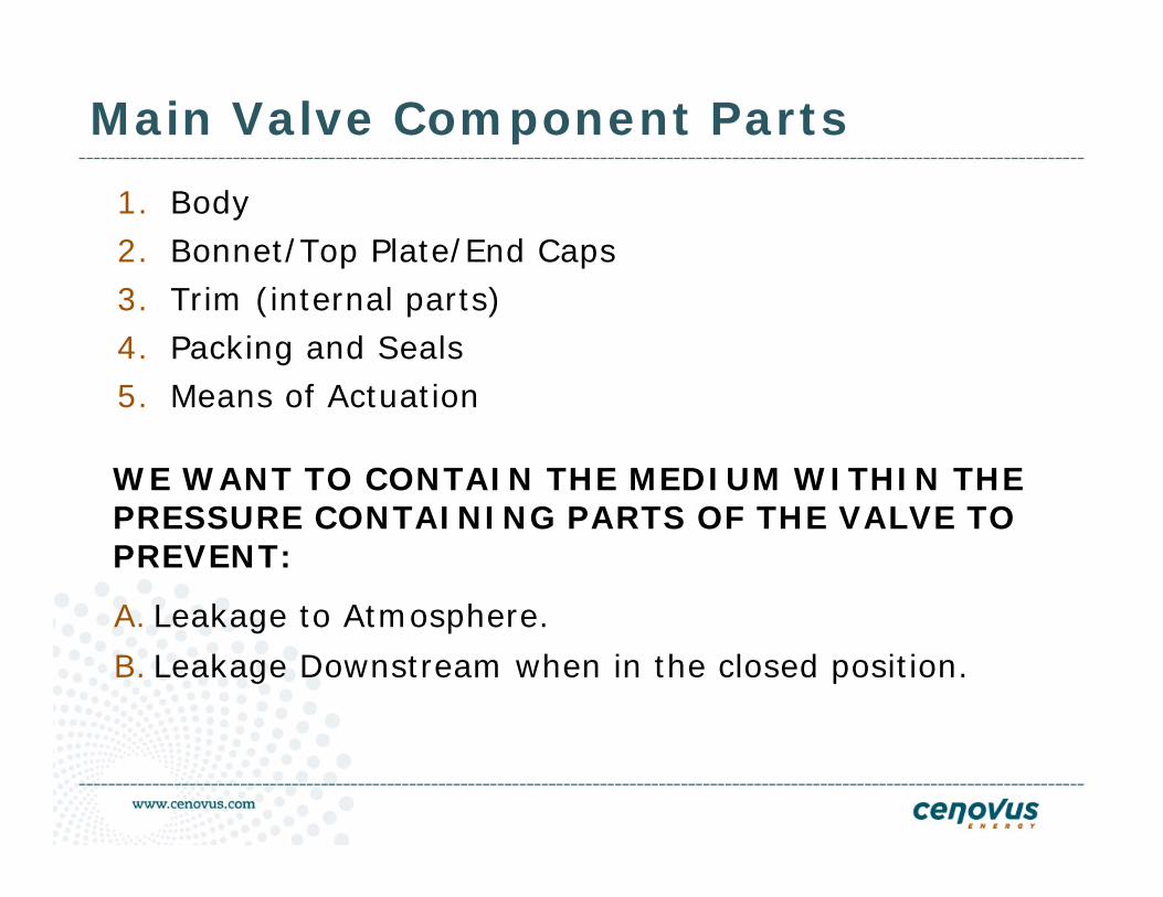
Main Valve Component Parts
1. Body2. Bonnet/Top Plate/End Caps3. Trim (internal parts)4. Packing and Seals5. Means of Actuation
WE WANT TO CONTAIN THE MEDIUM WITHIN THE PRESSURE CONTAINING PARTS OF THE VALVE TO PREVENT:
A. Leakage to Atmosphere.
B. Leakage Downstream when in the closed position.
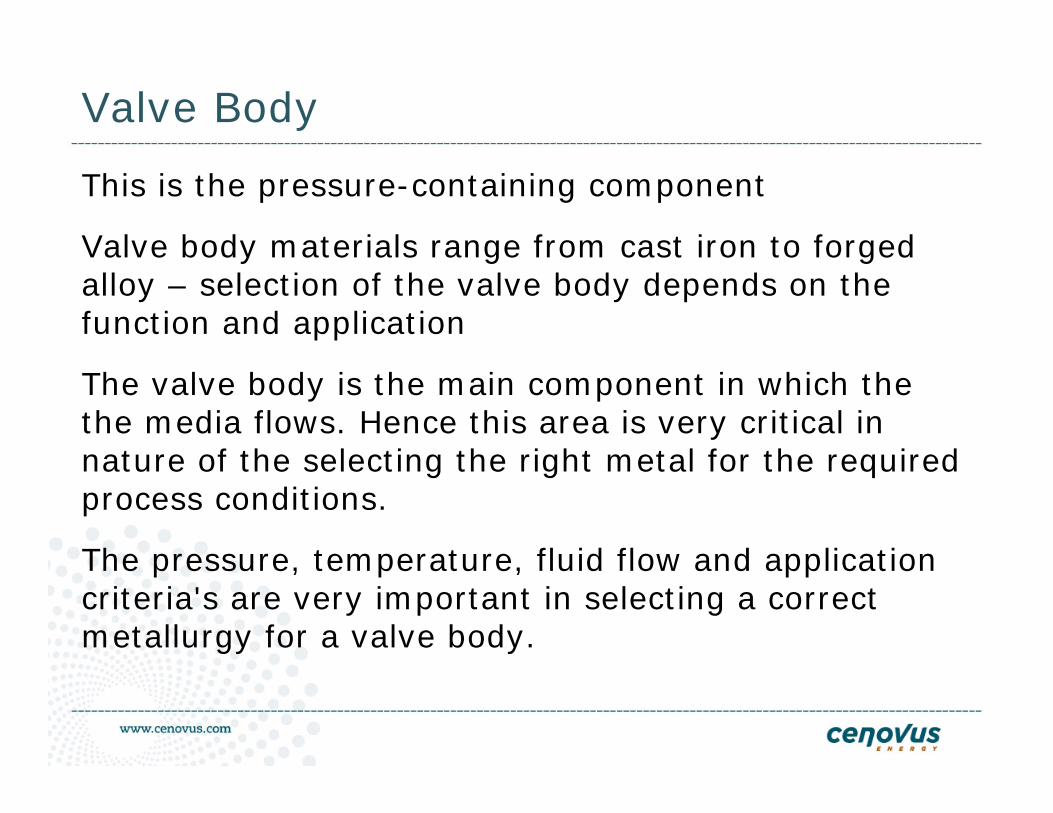
Valve Body
This is the pressure-containing component
Valve body materials range from cast iron to forged alloy – selection of the valve body depends on the function and application
The valve body is the main component in which the the media flows. Hence this area is very critical in nature of the selecting the right metal for the required process conditions.
The pressure, temperature, fluid flow and application criteria's are very important in selecting a correct metallurgy for a valve body.
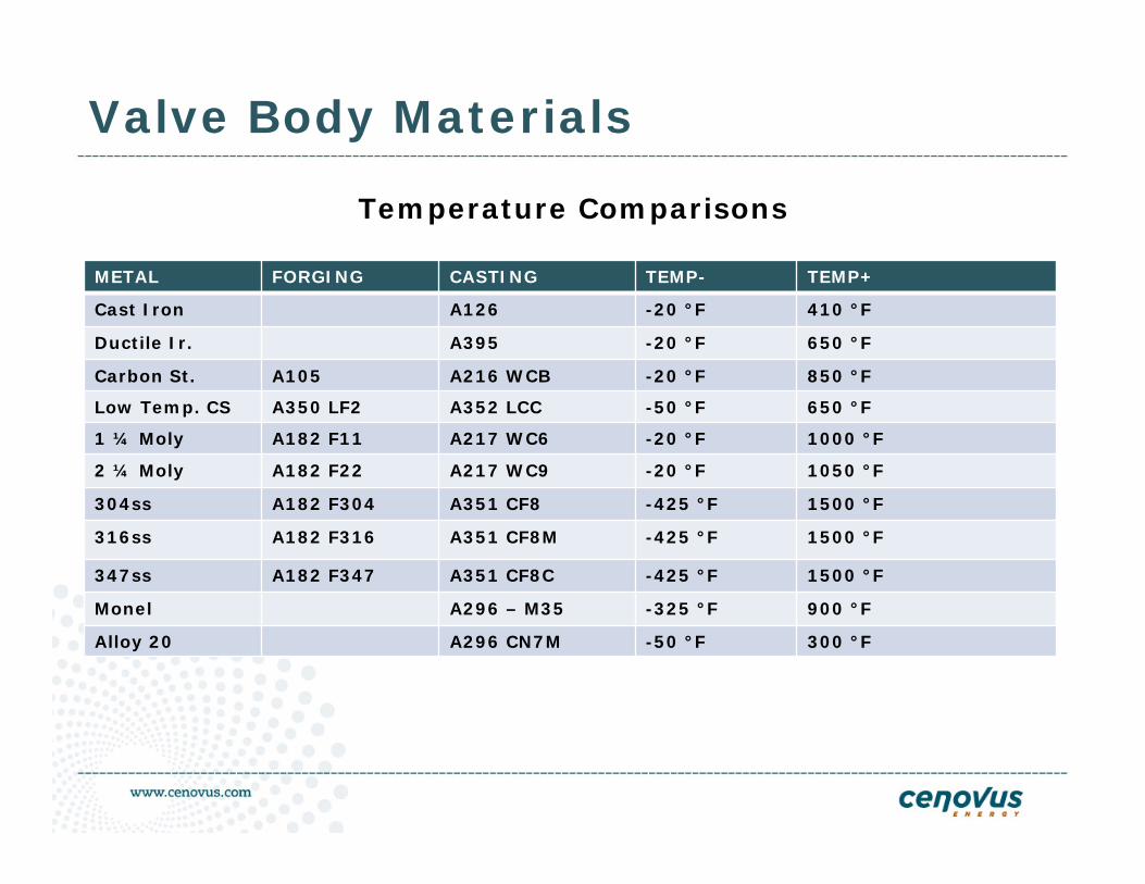
Valve Body Materials
Temperature Comparisons
METAL FORGING CASTING TEMP- TEMP+
Cast Iron A126 -20 °F 410 °F
Ductile Ir. A395 -20 °F 650 °F
Carbon St. A105 A216 WCB -20 °F 850 °F
Low Temp. CS A350 LF2 A352 LCC -50 °F 650 °F
1 ¼ Moly A182 F11 A217 WC6 -20 °F 1000 °F
2 ¼ Moly A182 F22 A217 WC9 -20 °F 1050 °F
304ss A182 F304 A351 CF8 -425 °F 1500 °F
316ss A182 F316 A351 CF8M -425 °F 1500 °F
347ss A182 F347 A351 CF8C -425 °F 1500 °F
Monel A296 – M35 -325 °F 900 °F
Alloy 20 A296 CN7M -50 °F 300 °F
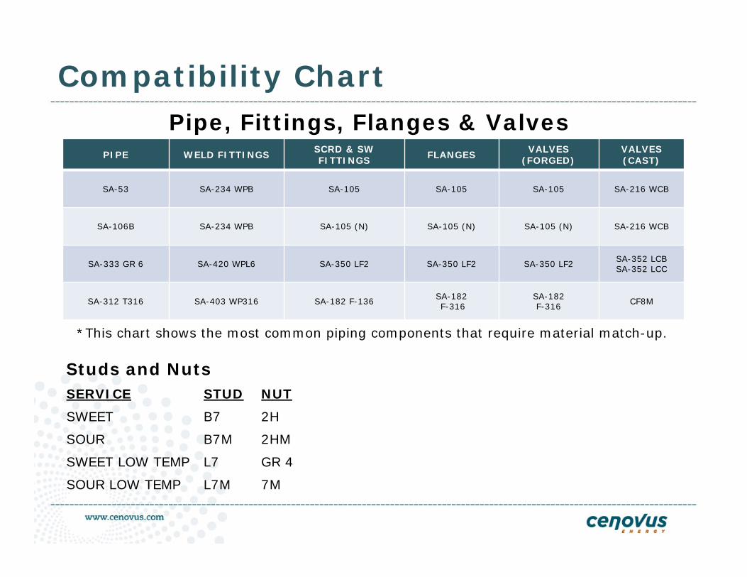
Compatibility Chart
PIPE WELD FITTINGS SCRD & SW FITTINGS FLANGES VALVES
(FORGED)VALVES(CAST)
SA-53 SA-234 WPB SA-105 SA-105 SA-105 SA-216 WCB
SA-106B SA-234 WPB SA-105 (N) SA-105 (N) SA-105 (N) SA-216 WCB
SA-333 GR 6 SA-420 WPL6 SA-350 LF2 SA-350 LF2 SA-350 LF2 SA-352 LCBSA-352 LCC
SA-312 T316 SA-403 WP316 SA-182 F-136 SA-182F-316
SA-182 F-316 CF8M
Pipe, Fittings, Flanges & Valves
*This chart shows the most common piping components that require material match-up.
Studs and NutsSERVICE STUD NUT
SWEET B7 2H
SOUR B7M 2HM
SWEET LOW TEMP L7 GR 4
SOUR LOW TEMP L7M 7M
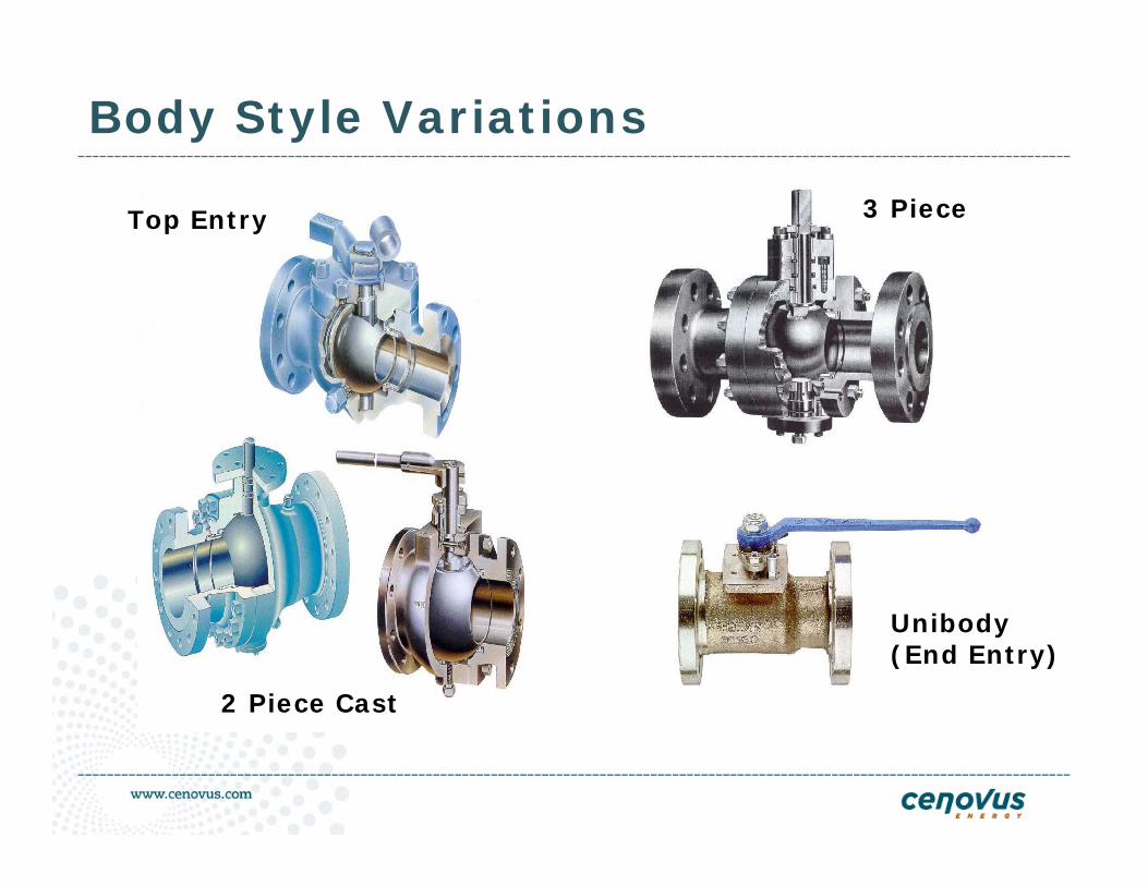
Body Style Variations
Top Entry
2 Piece Cast
3 Piece
Unibody(End Entry)
What is the media, what is the temperature, what is the operating pressure, what are the maximum design conditions? Is the media corrosive, abrasive, clean, dirty? Will there be high pressure drops? What type of trim do I need to stand up to these conditions?
Over the years, valve trim has evolved into a limited number of materials which have the necessary balance of physical and chemical properties to give good performance in a wide variety of applications.
Trim Selection
Factors Determining Trim Selection
1. Physical Properties
2. Erosion Considerations
3. Corrosion Considerations
4. Ease of Casting/Forming/Machining
5. Relative Cost
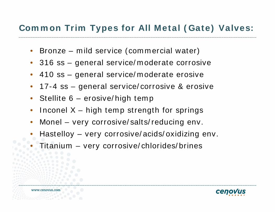
Common Trim Types for All Metal (Gate) Valves:
• Bronze – mild service (commercial water)
• 316 ss – general service/moderate corrosive
• 410 ss – general service/moderate erosive
• 17-4 ss – general service/corrosive & erosive
• Stellite 6 – erosive/high temp
• Inconel X – high temp strength for springs
• Monel – very corrosive/salts/reducing env.
• Hastelloy – very corrosive/acids/oxidizing env.
• Titanium – very corrosive/chlorides/brines
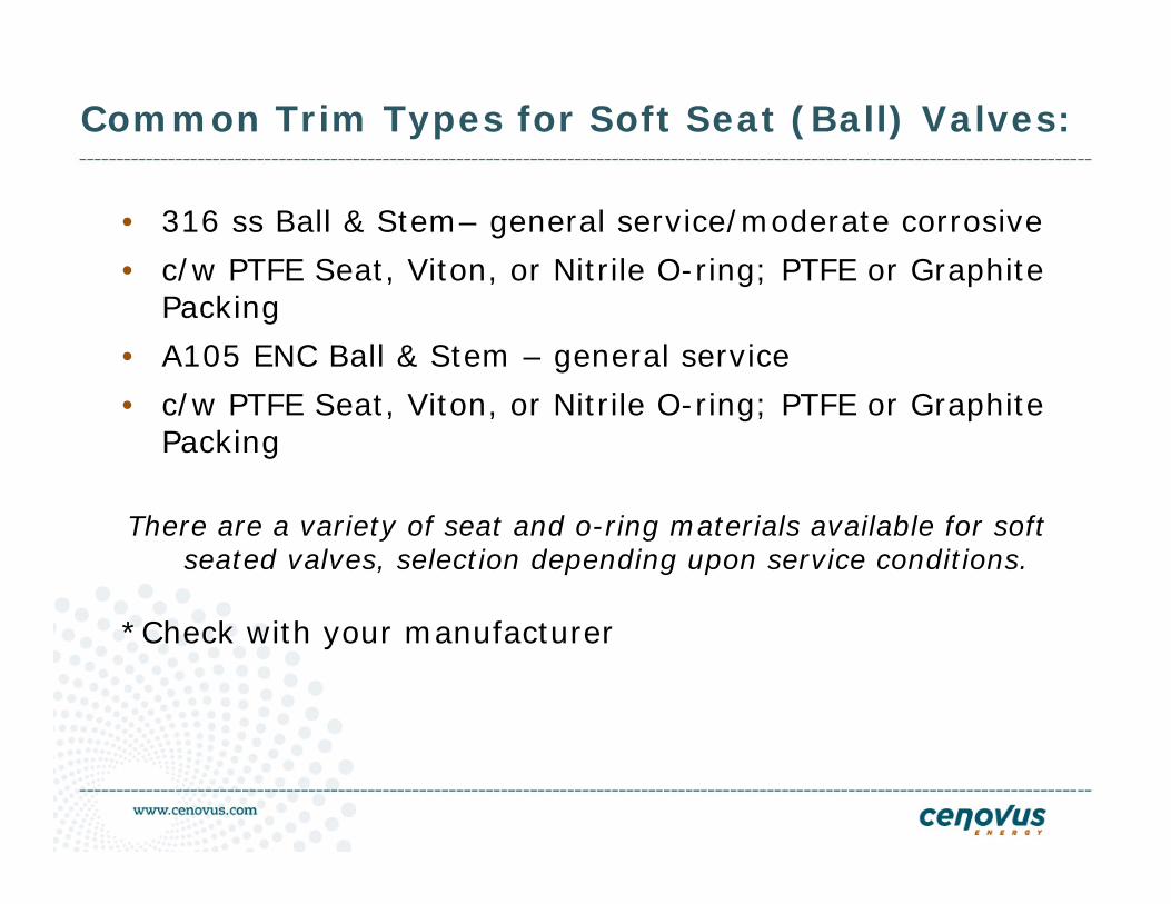
Common Trim Types for Soft Seat (Ball) Valves:
• 316 ss Ball & Stem– general service/moderate corrosive
• c/w PTFE Seat, Viton, or Nitrile O-ring; PTFE or Graphite Packing
• A105 ENC Ball & Stem – general service
• c/w PTFE Seat, Viton, or Nitrile O-ring; PTFE or Graphite Packing
There are a variety of seat and o-ring materials available for soft seated valves, selection depending upon service conditions.
*Check with your manufacturer
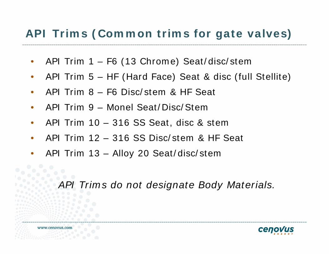
API Trims (Common trims for gate valves)
• API Trim 1 – F6 (13 Chrome) Seat/disc/stem
• API Trim 5 – HF (Hard Face) Seat & disc (full Stellite)
• API Trim 8 – F6 Disc/stem & HF Seat
• API Trim 9 – Monel Seat/Disc/Stem
• API Trim 10 – 316 SS Seat, disc & stem
• API Trim 12 – 316 SS Disc/stem & HF Seat
• API Trim 13 – Alloy 20 Seat/disc/stem
API Trims do not designate Body Materials.
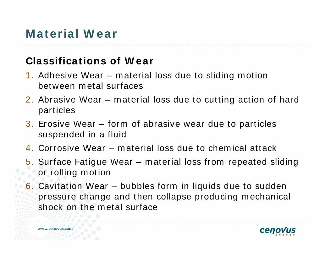
Material Wear
Classifications of Wear1. Adhesive Wear – material loss due to sliding motion
between metal surfaces
2. Abrasive Wear – material loss due to cutting action of hard particles
3. Erosive Wear – form of abrasive wear due to particles suspended in a fluid
4. Corrosive Wear – material loss due to chemical attack
5. Surface Fatigue Wear – material loss from repeated sliding or rolling motion
6. Cavitation Wear – bubbles form in liquids due to sudden pressure change and then collapse producing mechanical shock on the metal surface
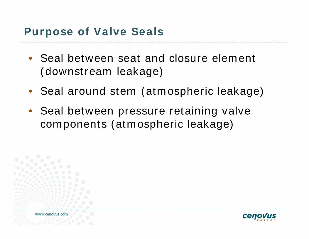
Purpose of Valve Seals
• Seal between seat and closure element (downstream leakage)
• Seal around stem (atmospheric leakage)
• Seal between pressure retaining valve components (atmospheric leakage)
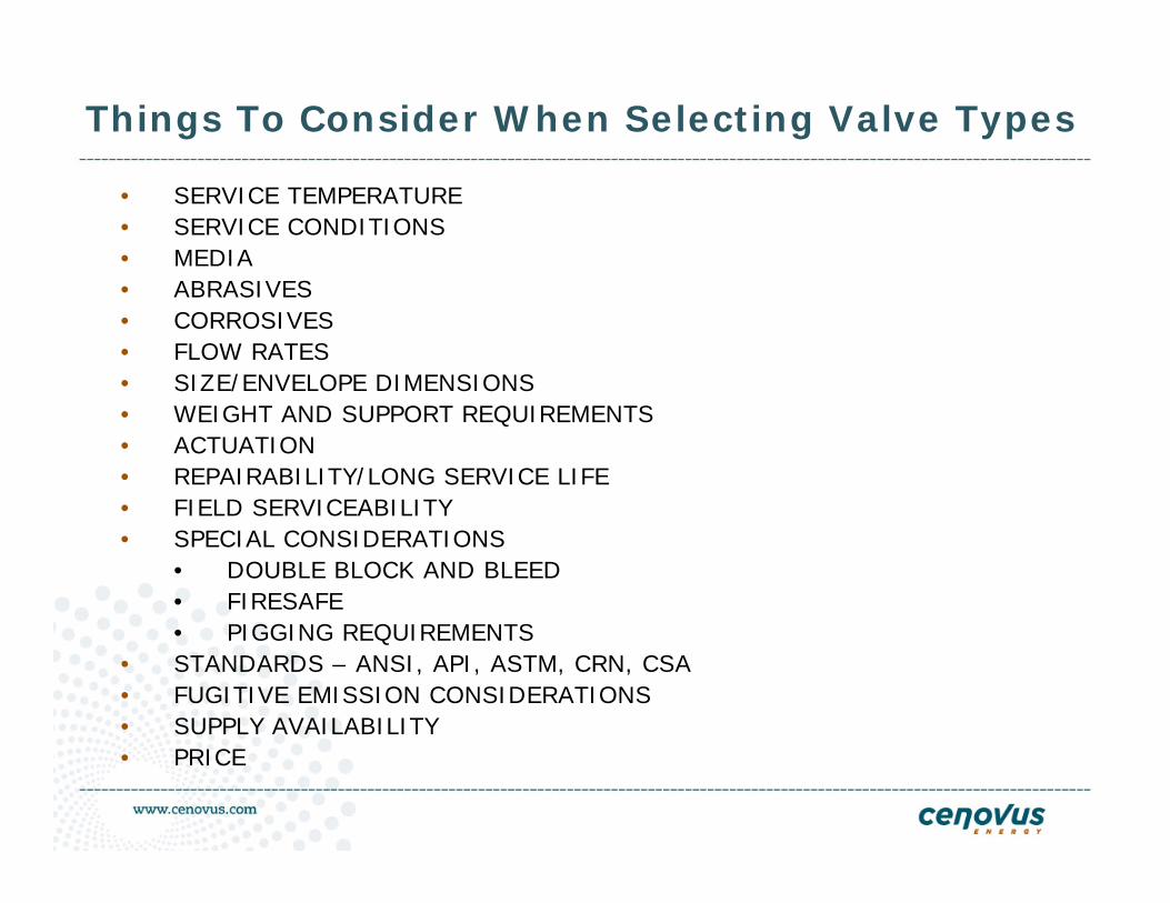
• SERVICE TEMPERATURE• SERVICE CONDITIONS• MEDIA• ABRASIVES• CORROSIVES• FLOW RATES• SIZE/ENVELOPE DIMENSIONS• WEIGHT AND SUPPORT REQUIREMENTS• ACTUATION• REPAIRABILITY/LONG SERVICE LIFE• FIELD SERVICEABILITY• SPECIAL CONSIDERATIONS
• DOUBLE BLOCK AND BLEED• FIRESAFE• PIGGING REQUIREMENTS
• STANDARDS – ANSI, API, ASTM, CRN, CSA• FUGITIVE EMISSION CONSIDERATIONS• SUPPLY AVAILABILITY• PRICE
Things To Consider When Selecting Valve Types
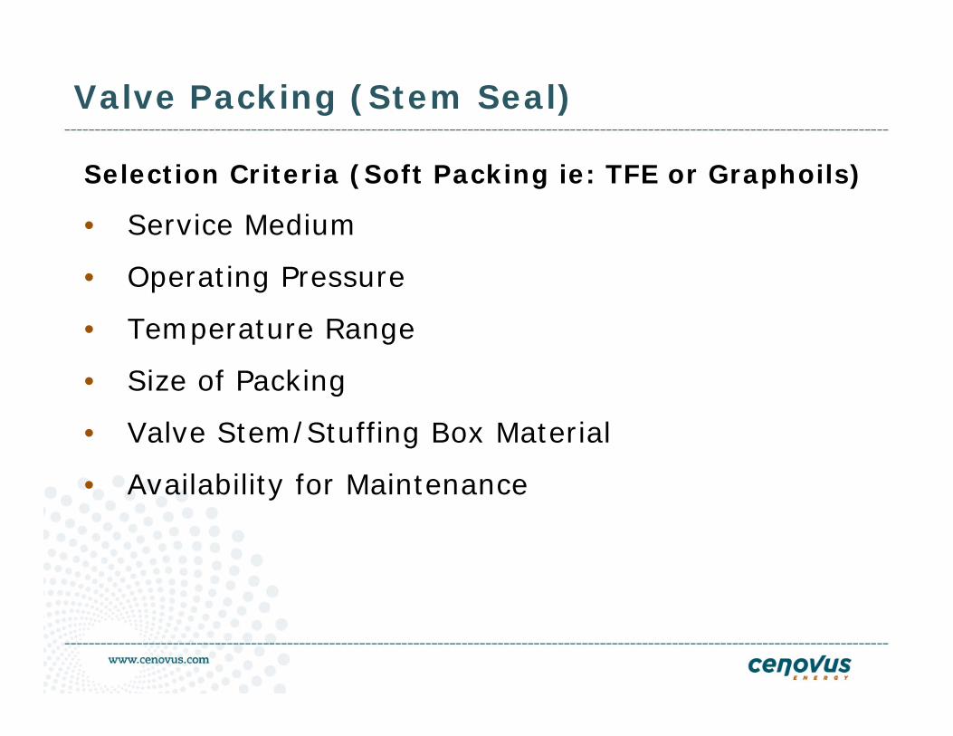
Valve Packing (Stem Seal)
Selection Criteria (Soft Packing ie: TFE or Graphoils)
• Service Medium
• Operating Pressure
• Temperature Range
• Size of Packing
• Valve Stem/Stuffing Box Material
• Availability for Maintenance
Some Specific Valve Types
Ball Valves
Gate Valves
Check Valves
Double Block and Bleed Valves
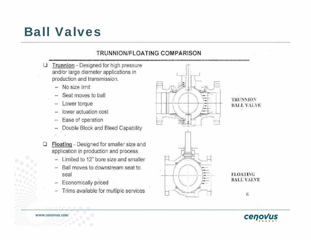
Ball Valves
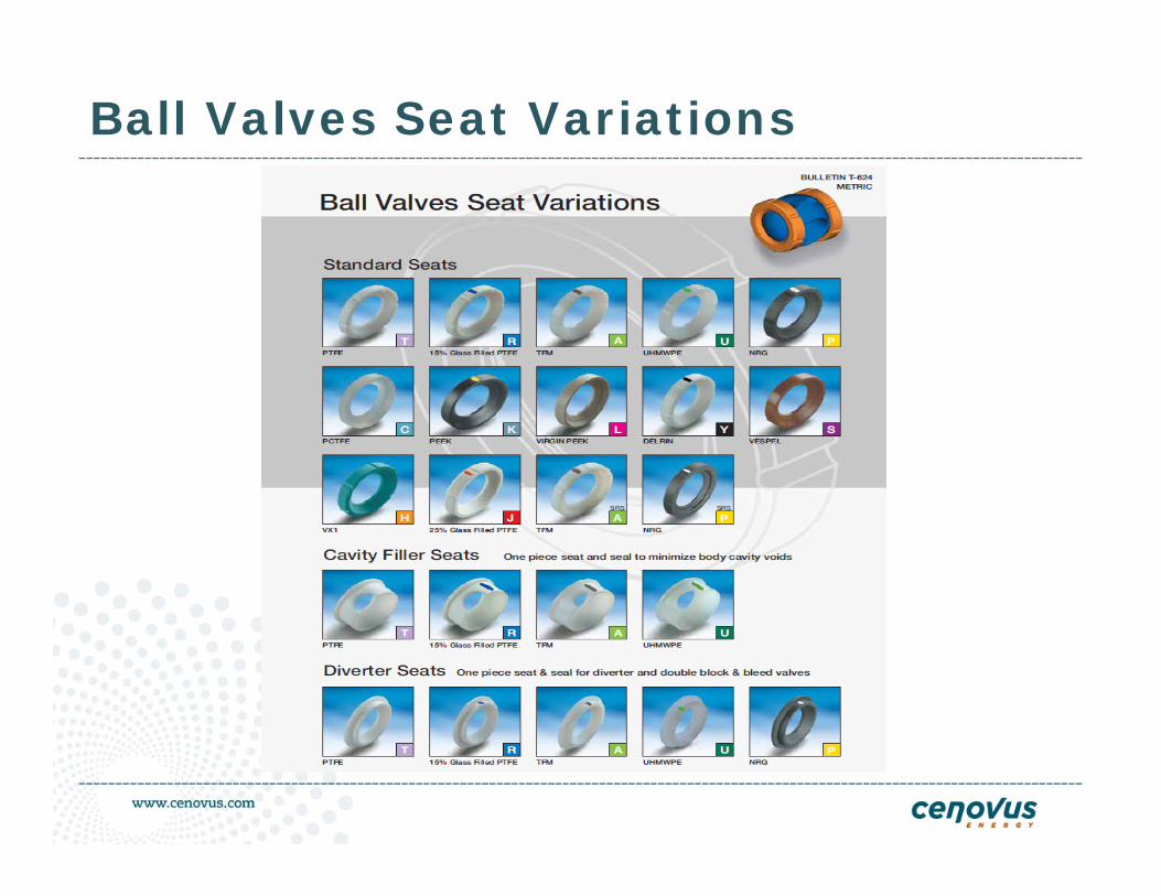
Ball Valves Seat Variations
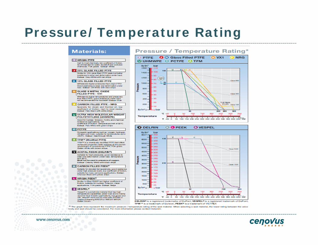
Pressure/Temperature Rating
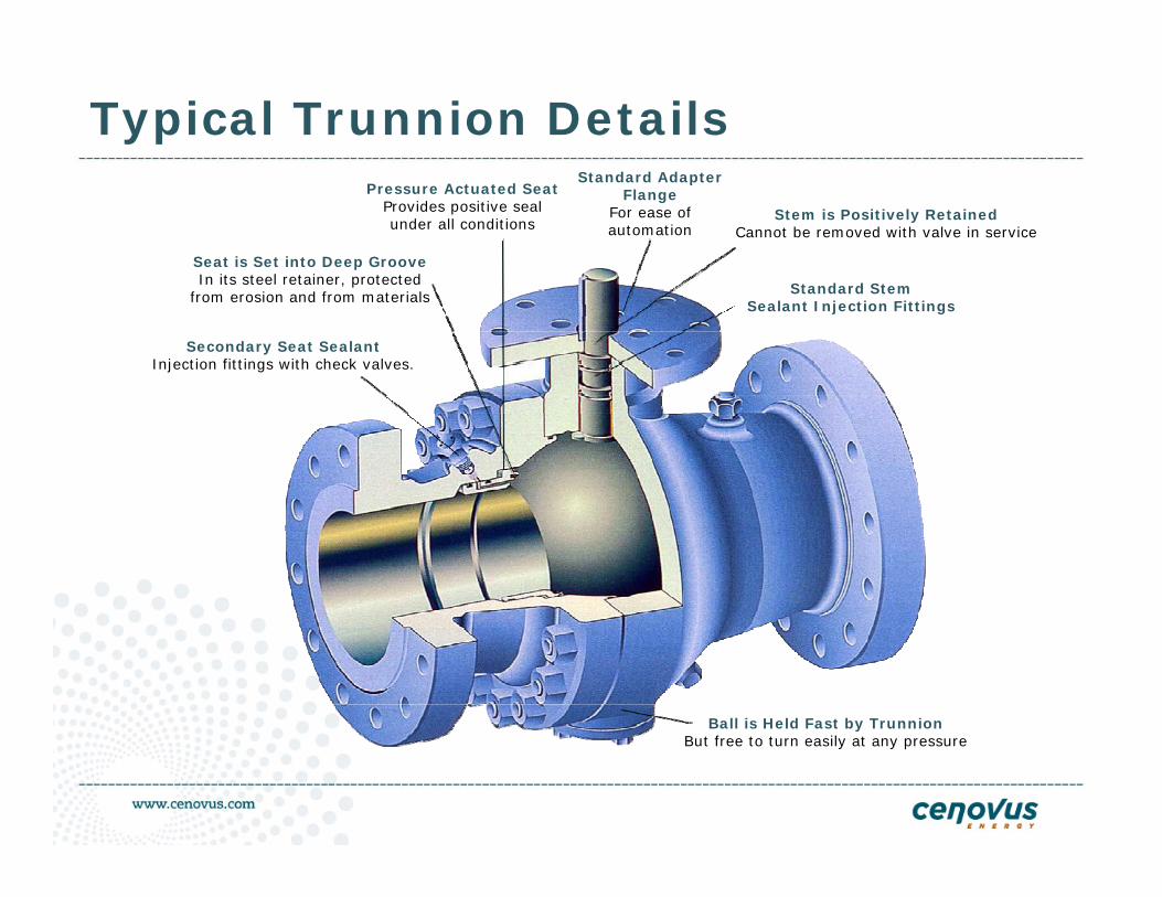
Typical Trunnion Details
Secondary Seat SealantInjection fittings with check valves.
Seat is Set into Deep GrooveIn its steel retainer, protected
from erosion and from materials
Pressure Actuated SeatProvides positive seal under all conditions
Standard Adapter Flange
For ease of automation
Stem is Positively RetainedCannot be removed with valve in service
Standard Stem Sealant Injection Fittings
Ball is Held Fast by TrunnionBut free to turn easily at any pressure
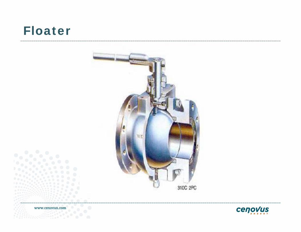
Floater
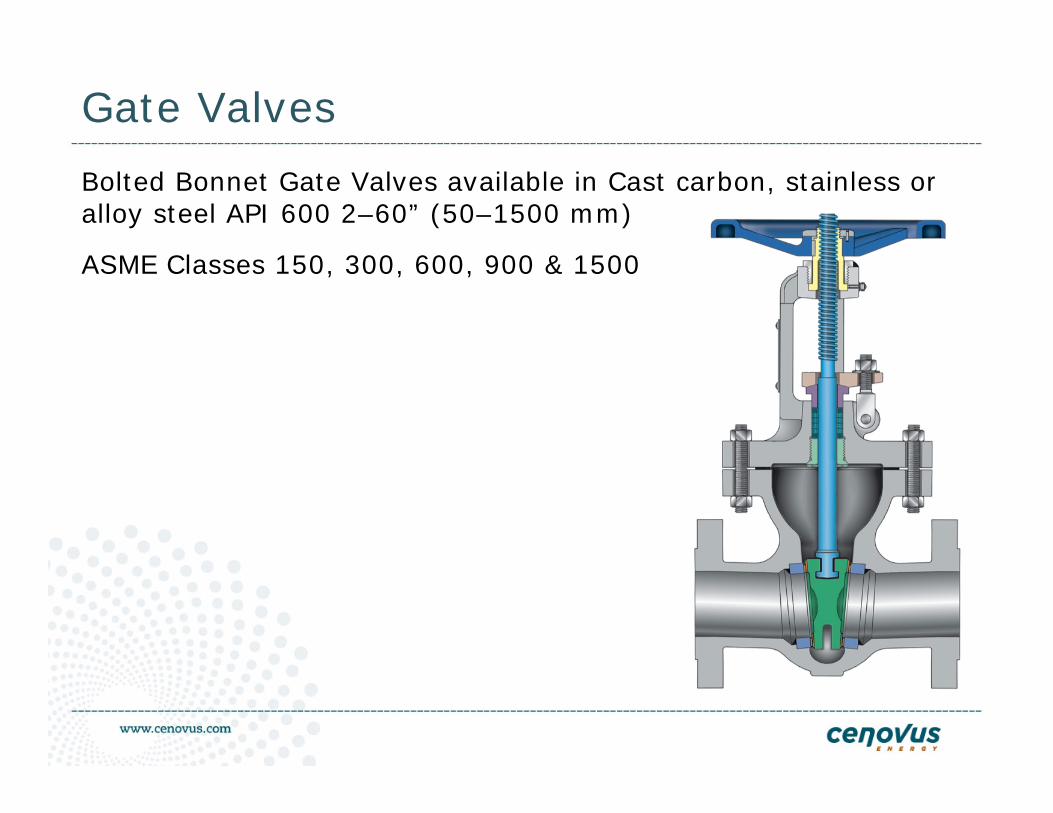
Gate Valves
Bolted Bonnet Gate Valves available in Cast carbon, stainless oralloy steel API 600 2–60” (50–1500 mm)
ASME Classes 150, 300, 600, 900 & 1500
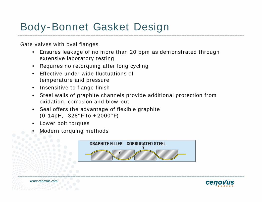
Body-Bonnet Gasket DesignGate valves with oval flanges
• Ensures leakage of no more than 20 ppm as demonstrated through extensive laboratory testing
• Requires no retorquing after long cycling• Effective under wide fluctuations of
temperature and pressure• Insensitive to flange finish• Steel walls of graphite channels provide additional protection from
oxidation, corrosion and blow-out• Seal offers the advantage of flexible graphite
(0-14pH, -328°F to +2000°F)• Lower bolt torques• Modern torquing methods
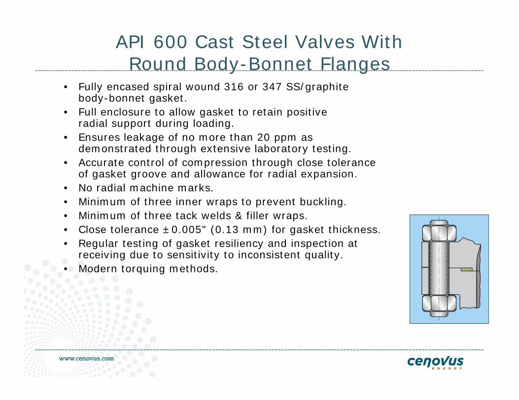
API 600 Cast Steel Valves WithRound Body-Bonnet Flanges
• Fully encased spiral wound 316 or 347 SS/graphite body-bonnet gasket.
• Full enclosure to allow gasket to retain positive radial support during loading.
• Ensures leakage of no more than 20 ppm as demonstrated through extensive laboratory testing.
• Accurate control of compression through close tolerance of gasket groove and allowance for radial expansion.
• No radial machine marks.• Minimum of three inner wraps to prevent buckling.• Minimum of three tack welds & filler wraps.• Close tolerance ±0.005" (0.13 mm) for gasket thickness.• Regular testing of gasket resiliency and inspection at
receiving due to sensitivity to inconsistent quality.• Modern torquing methods.
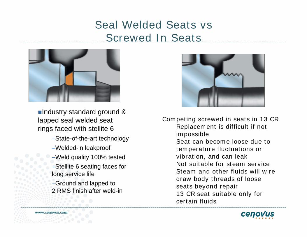
Seal Welded Seats vsScrewed In Seats
Industry standard ground & lapped seal welded seat rings faced with stellite 6
–State-of-the-art technology–Welded-in leakproof–Weld quality 100% tested–Stellite 6 seating faces for long service life–Ground and lapped to 2 RMS finish after weld-in
Competing screwed in seats in 13 CRReplacement is difficult if not impossibleSeat can become loose due to temperature fluctuations or vibration, and can leakNot suitable for steam service Steam and other fluids will wire draw body threads of loose seats beyond repair13 CR seat suitable only for certain fluids
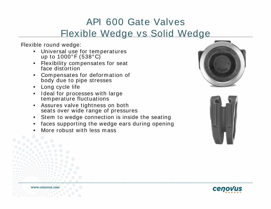
API 600 Gate ValvesFlexible Wedge vs Solid Wedge
Flexible round wedge:• Universal use for temperatures
up to 1000°F (538°C)• Flexibility compensates for seat
face distortion• Compensates for deformation of
body due to pipe stresses• Long cycle life• Ideal for processes with large
temperature fluctuations• Assures valve tightness on both
seats over wide range of pressures• Stem to wedge connection is inside the seating • faces supporting the wedge ears during opening• More robust with less mass
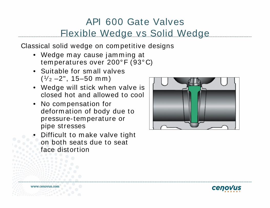
API 600 Gate ValvesFlexible Wedge vs Solid Wedge
Classical solid wedge on competitive designs• Wedge may cause jamming at
temperatures over 200°F (93°C)• Suitable for small valves
(1⁄2 –2", 15–50 mm)• Wedge will stick when valve is
closed hot and allowed to cool• No compensation for
deformation of body due to pressure-temperature or pipe stresses
• Difficult to make valve tight on both seats due to seat face distortion
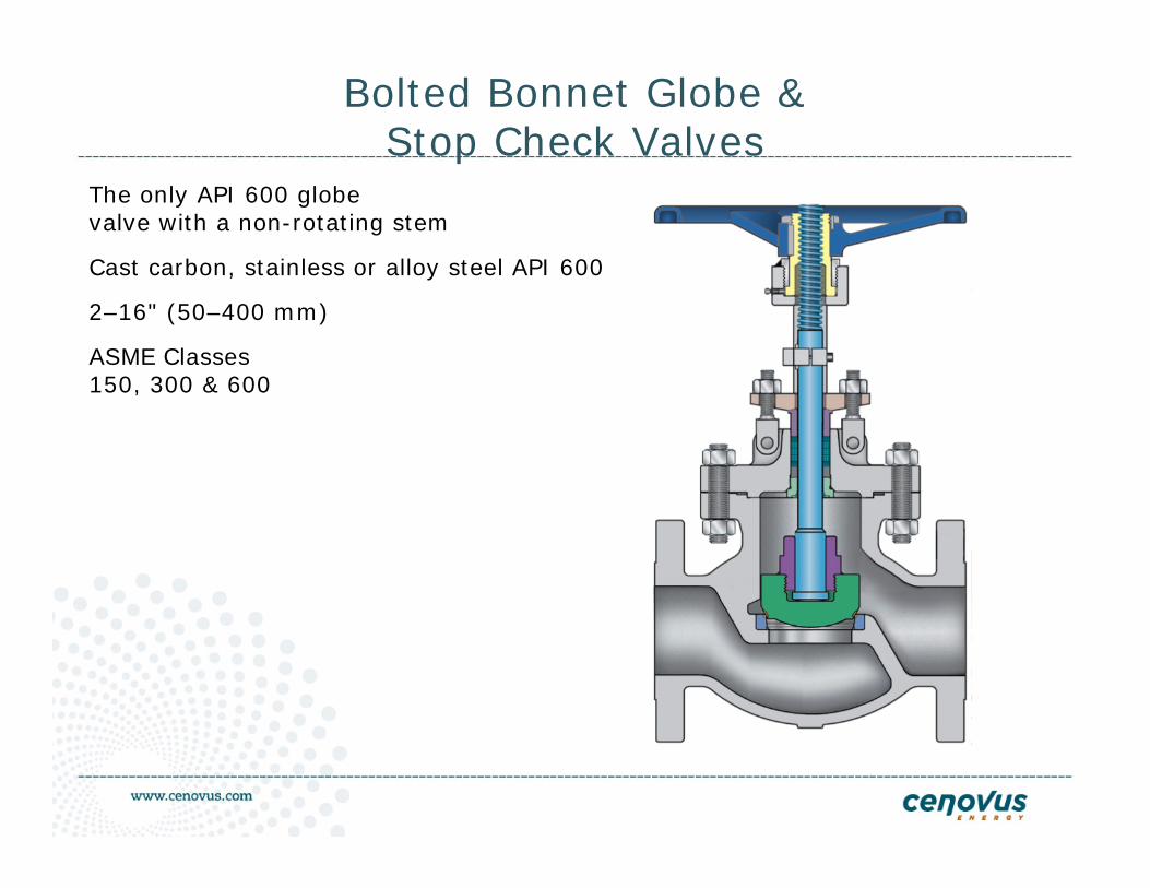
Bolted Bonnet Globe &Stop Check Valves
The only API 600 globe valve with a non-rotating stem
Cast carbon, stainless or alloy steel API 600
2–16" (50–400 mm)
ASME Classes 150, 300 & 600
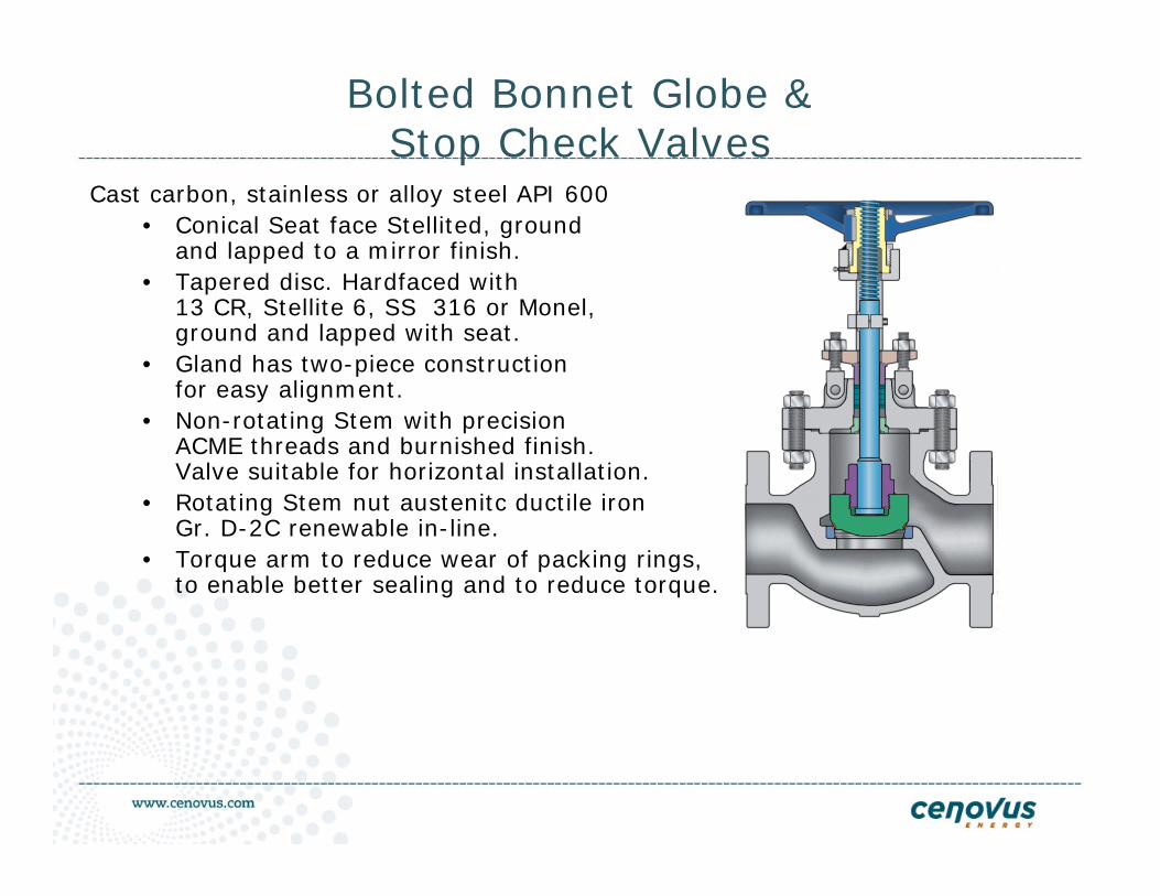
Bolted Bonnet Globe &Stop Check Valves
Cast carbon, stainless or alloy steel API 600• Conical Seat face Stellited, ground
and lapped to a mirror finish. • Tapered disc. Hardfaced with
13 CR, Stellite 6, SS 316 or Monel, ground and lapped with seat.
• Gland has two-piece construction for easy alignment.
• Non-rotating Stem with precision ACME threads and burnished finish. Valve suitable for horizontal installation.
• Rotating Stem nut austenitc ductile iron Gr. D-2C renewable in-line.
• Torque arm to reduce wear of packing rings,to enable better sealing and to reduce torque.
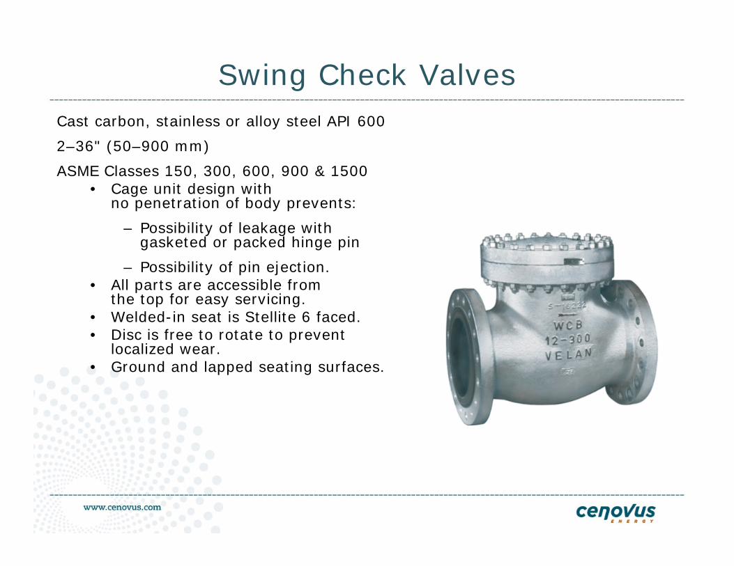
Swing Check ValvesCast carbon, stainless or alloy steel API 600
2–36" (50–900 mm)
ASME Classes 150, 300, 600, 900 & 1500• Cage unit design with
no penetration of body prevents:
– Possibility of leakage with gasketed or packed hinge pin
– Possibility of pin ejection.• All parts are accessible from
the top for easy servicing.• Welded-in seat is Stellite 6 faced.• Disc is free to rotate to prevent
localized wear.• Ground and lapped seating surfaces.
Definition of Double Block and Bleed
API 6D –21st Edition
“A valve with two seating surfaces which, in the closed position, provides blockage of flow from both valve ends when the cavity between the seating surface is vented or drained. A means shall be provided for draining or venting the cavity between the seating surfaces.”
The body cavity can be vented or drained in the open or closed position.
The valve can be tested for integrity and safeguard for downstream work.
Design and Procurement
Valve designs must comply with known, published standards such as
• API
• ASTM
• AWWA
• CSA
• ASME
• MSS-SP
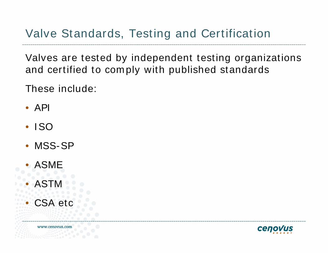
Valve Standards, Testing and Certification
Valves are tested by independent testing organizations and certified to comply with published standards
These include:
• API
• ISO
• MSS-SP
• ASME
• ASTM
• CSA etc
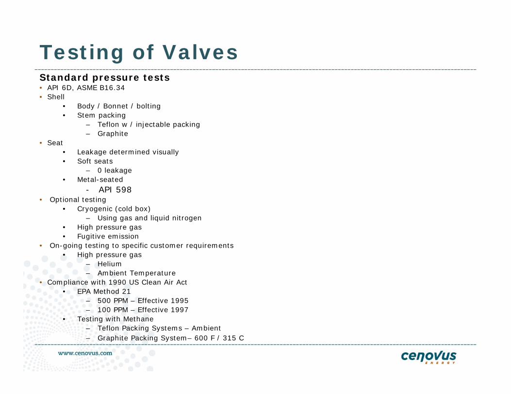
Testing of ValvesStandard pressure tests• API 6D, ASME B16.34 • Shell
• Body / Bonnet / bolting• Stem packing
– Teflon w / injectable packing– Graphite
• Seat• Leakage determined visually• Soft seats
– 0 leakage• Metal-seated
- API 598• Optional testing
• Cryogenic (cold box)– Using gas and liquid nitrogen
• High pressure gas• Fugitive emission
• On-going testing to specific customer requirements• High pressure gas
– Helium– Ambient Temperature
• Compliance with 1990 US Clean Air Act• EPA Method 21
– 500 PPM – Effective 1995– 100 PPM – Effective 1997
• Testing with Methane– Teflon Packing Systems – Ambient– Graphite Packing System– 600 F / 315 C
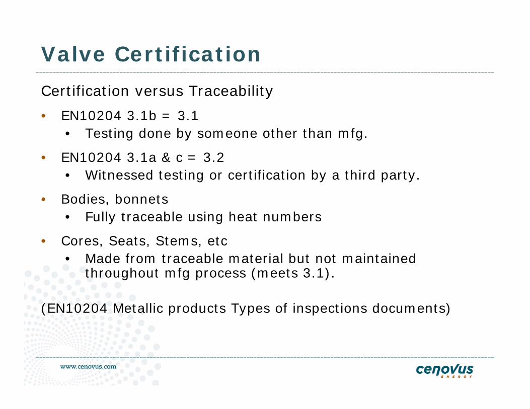
Valve Certification
Certification versus Traceability
• EN10204 3.1b = 3.1• Testing done by someone other than mfg.
• EN10204 3.1a & c = 3.2• Witnessed testing or certification by a third party.
• Bodies, bonnets• Fully traceable using heat numbers
• Cores, Seats, Stems, etc• Made from traceable material but not maintained
throughout mfg process (meets 3.1).
(EN10204 Metallic products Types of inspections documents)
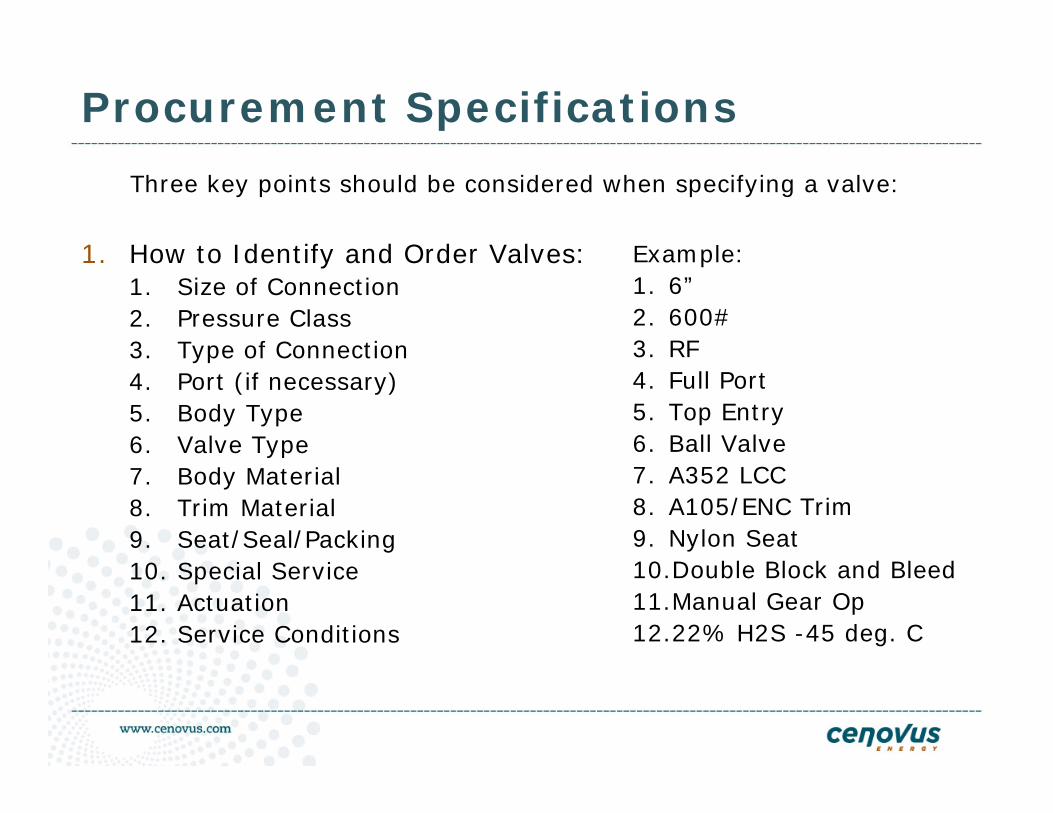
Procurement Specifications
1. How to Identify and Order Valves:1. Size of Connection2. Pressure Class 3. Type of Connection 4. Port (if necessary) 5. Body Type 6. Valve Type 7. Body Material 8. Trim Material 9. Seat/Seal/Packing10. Special Service11. Actuation12. Service Conditions
Three key points should be considered when specifying a valve:
Example:1. 6”2. 600# 3. RF 4. Full Port5. Top Entry 6. Ball Valve 7. A352 LCC 8. A105/ENC Trim 9. Nylon Seat10.Double Block and Bleed 11.Manual Gear Op 12.22% H2S -45 deg. C
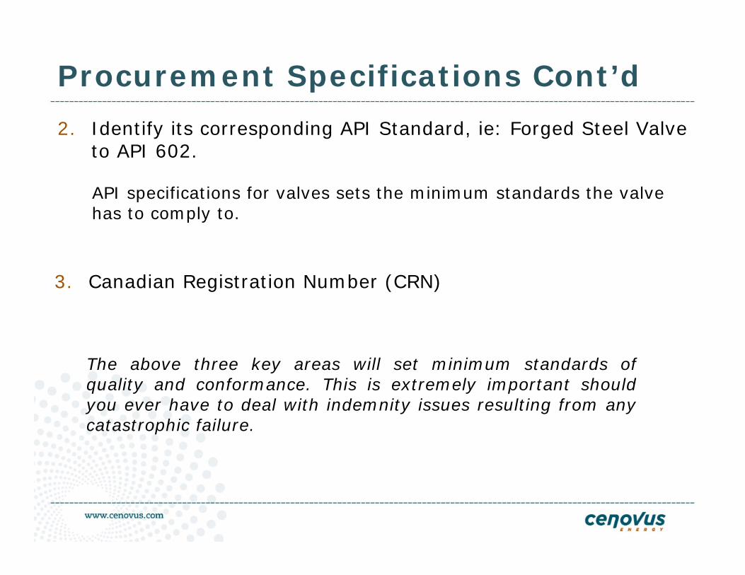
Procurement Specifications Cont’d
2. Identify its corresponding API Standard, ie: Forged Steel Valve to API 602.
API specifications for valves sets the minimum standards the valve has to comply to.
3. Canadian Registration Number (CRN)
The above three key areas will set minimum standards of quality and conformance. This is extremely important should you ever have to deal with indemnity issues resulting from any catastrophic failure.
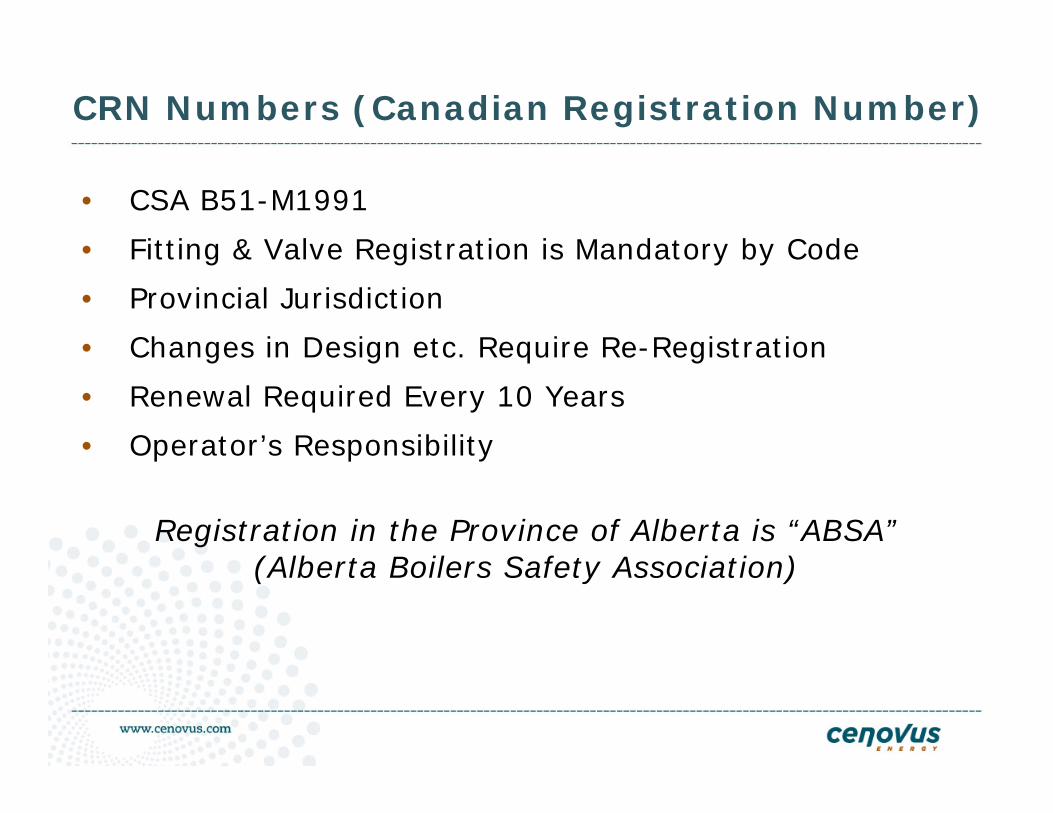
CRN Numbers (Canadian Registration Number)
• CSA B51-M1991
• Fitting & Valve Registration is Mandatory by Code
• Provincial Jurisdiction
• Changes in Design etc. Require Re-Registration
• Renewal Required Every 10 Years
• Operator’s Responsibility
Registration in the Province of Alberta is “ABSA”(Alberta Boilers Safety Association)
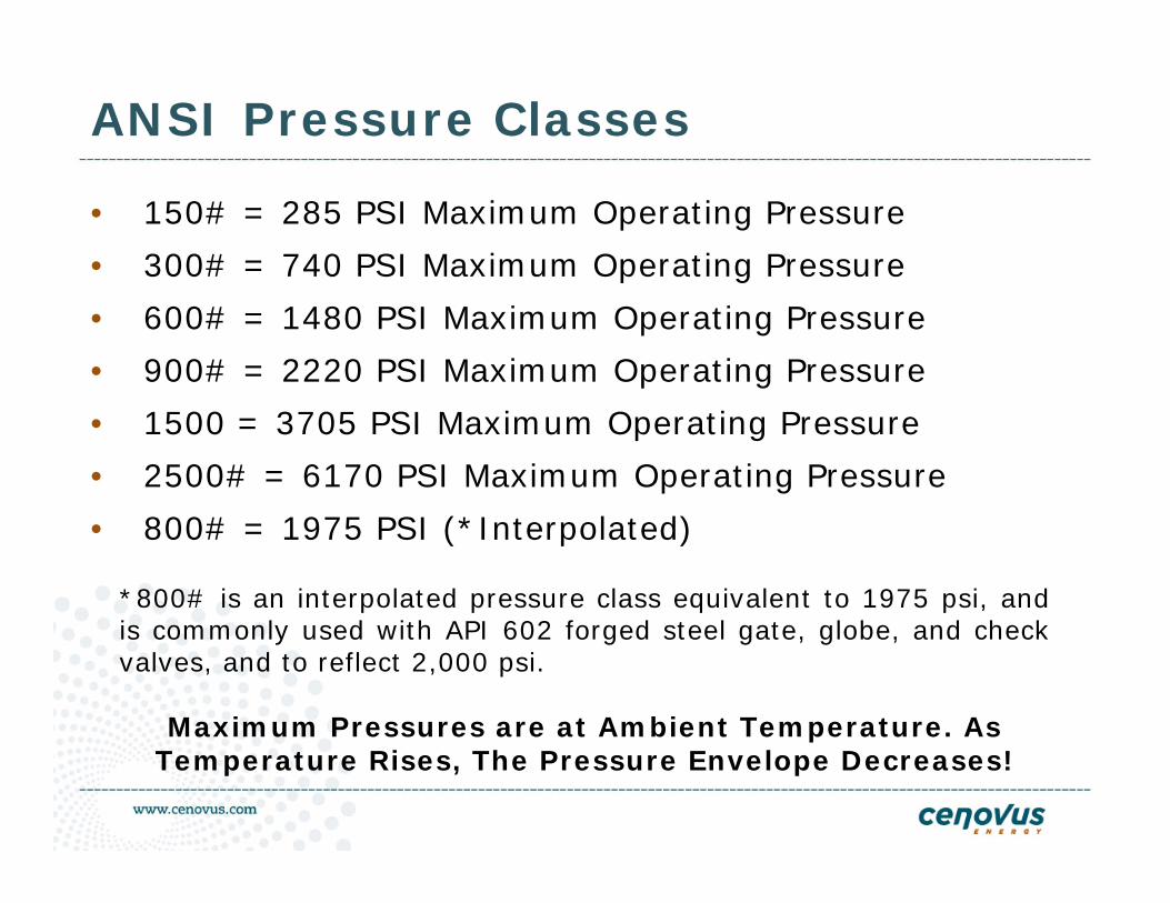
ANSI Pressure Classes
• 150# = 285 PSI Maximum Operating Pressure
• 300# = 740 PSI Maximum Operating Pressure
• 600# = 1480 PSI Maximum Operating Pressure
• 900# = 2220 PSI Maximum Operating Pressure
• 1500 = 3705 PSI Maximum Operating Pressure
• 2500# = 6170 PSI Maximum Operating Pressure
• 800# = 1975 PSI (*Interpolated)
*800# is an interpolated pressure class equivalent to 1975 psi, and is commonly used with API 602 forged steel gate, globe, and check valves, and to reflect 2,000 psi.
Maximum Pressures are at Ambient Temperature. As Temperature Rises, The Pressure Envelope Decreases!
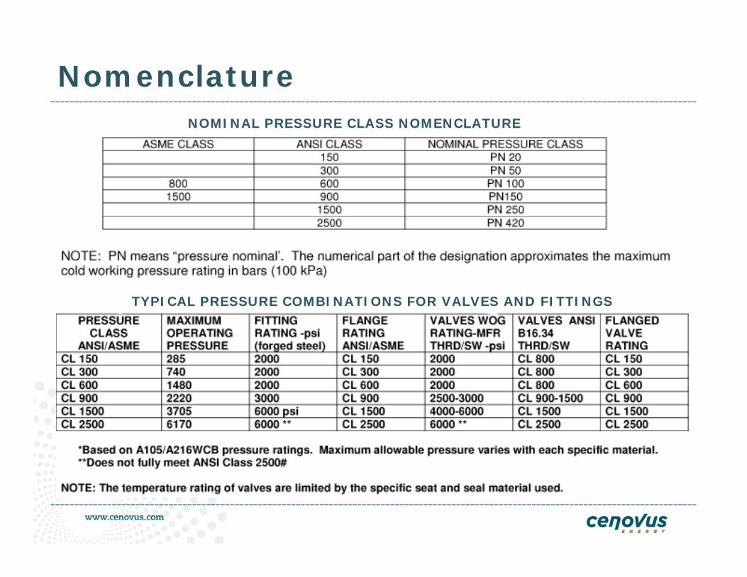
NomenclatureNOMINAL PRESSURE CLASS NOMENCLATURE
TYPICAL PRESSURE COMBINATIONS FOR VALVES AND FITTINGS
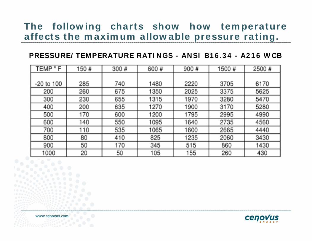
The following charts show how temperature affects the maximum allowable pressure rating.
PRESSURE/TEMPERATURE RATINGS - ANSI B16.34 - A216 WCB
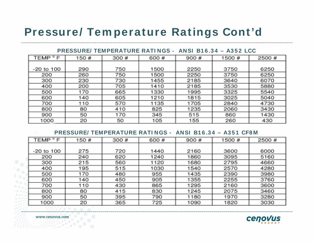
Pressure/Temperature Ratings Cont’d
PRESSURE/TEMPERATURE RATINGS - ANSI B16.34 – A352 LCC
PRESSURE/TEMPERATURE RATINGS - ANSI B16.34 – A351 CF8M
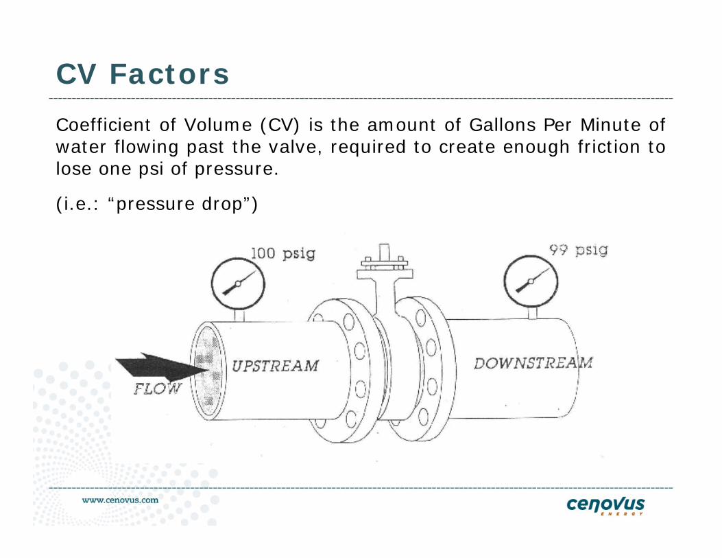
CV Factors
Coefficient of Volume (CV) is the amount of Gallons Per Minute of water flowing past the valve, required to create enough friction to lose one psi of pressure.
(i.e.: “pressure drop”)
Governing Codes and Standards
• ASME – American Society of Mechanical Engineers
• API – American Petroleum Institute
• ANSI – American National Standards Institute
• MSS – Manufacturer’s Standards Society
• NACE – National Association of Corrosion Engineers
• CSA – Canadian Standards Association
• ISO – International Standards Organization
These standards govern body & trim materials, testing procedures and dimensional specifications.
Fire Safe Standards
Fire Safe Standards tests valves under simulated fire conditionsand defines how a valve is supposed to react under these conditions, and hopefully will dot the same under an “actual fire”. It looks at rapid heating and cooling, method of measuring temperature, test pressures, cycling, open and closed positions and allowable leak rates under these conditions.
API-607 (for plants and facilities) is a new standard so that everyone could test to the same spec for soft seated valves. There have been several revisions, the latest being the 4th edition. The 4th edition is more strict in its requirements than the previous 3rd edition. Not all manufacturers have met this new standards.
Fire Safe Standards Cont’d
API 6FA - This standard is more commonly used for fire safe Trunnion ball valves, & it’s recognized (also used internationally), for pipelines, gathering systems, terminals, etc. The standard used to be identical to API 607 until the arrival of the 4th edition.
EXES 3-14-1-2A - Exxon has their own fire burn test. They have additional requirements to API or BS such as rapid cooling and more stringent allowable leakage rates.
BS-6755 British Standard Institute - has been re-worded so its now similar to API 607 3rd edition.
ISO-10497 - European specification. Like British standards, the specification was very much like API 607 till the latest revision.
NACE MR0175/ISO15156• Oil production and drilling equipment began to fail in Canada and
the Western United States as reserves were developed that contained hydrogen sulfide (H2S).
• The mode of failure was sulfide stress cracking (SSC) that occurred below the conventional mechanical design stresses for equipment.
• Fatalities from an accident in West Texas prompted the Texas Railroad Commission to ask the industry to write a document to help prevent such incidents in the future.
• NACE members came together to write MR0175, the first materials recommendation from NACE issued in 1975.
• “It is the responsibility of the user to determine the operating conditions and to specify when this standard applies. The manufacturer is responsible for meeting metallurgical requirements. It is the user’s responsibility to ensure that a material will be satisfactory in the intended environment.”Cenovus Energy Inc is a user.
NACE MR0175/ISO15156
These are NOT users.
• An equipment manufacturer is NOT a user.
• A mill is NOT a user.
• A distributor is NOT a user.
• A consultant or contractor are NOT users.
If we specify a material, we are the only ones responsible for safe and reliable performance in the field.
There is another NACE standard that may be an acceptable substitute to MR0175 for most customers. That standard is NACE MR103 The material specifications in NACE MR0103 closely parallel earlier versions of MR0175 and is therefore the best choice for Cameron to quote unless expressly prohibited by customer’s specifications.
Tools in Grow your knowledge in Valve Industry areIn order to grow your valve knowledge we have following:
- Valve User Group, Alberta
- Valve Magazine, USA
- Valve World, Netherlands
- Valve Seminars/Conferences and trainings
- Valve Handbooks such as CRANE Flow of FLUIDS, TC Piping Book, FISHER Handbook, POWELL Valve Guide, Flowserve Valve Book, Cameron Valve Info etc.
More Valve Presentations - Double Block and Bleed Valves
- Non Slam Check Valves
- Control Valves 101
- PSV 101(Safety Valves)
- How to write Valve Specifications and understand Industry Standards
- Asset Integrity Management on Facilities and Valve Operations and Maintenance
- How to select the right valve for application
- Valve Soft Components and Role in Process at Various levels in a OilSands or Conventional Oil and Gas Facilities
- Valve Sizing and Selection using Flow of Fluids Software

Thank you all and Team Members of APEGGA to make
this event successful

Have a wonderful Wednesday
Questions?
Comments!
Suggestions Welcome
Contact: [email protected],
Tel 403-766-2028