valvepac series 760p valve positioner - dyna-flo · 15 psi) and converts it to a pneumatic output...
TRANSCRIPT

INSTALLATION AND SERVICE INSTRUCTIONSiemensEnergy & Automation
SD760-2 Rev. 2 April 2002
ValvePACTM
Series 760P
Valve Positioner
Our Positioners Control the Best Valves & Actuators in the World


SD760-2 Contents
April 2002 i
TABLE OF CONTENTS SECTION AND TITLE PAGE Preface ........................................................................................................................................................................ iv
1.0 INTRODUCTION ............................................................................................................................................. 1-1
1.1 SPECIFICATIONS.........................................................................................................................................1-2 1.2 MODEL DESIGNATION ..............................................................................................................................1-5 1.3 OPTION KITS................................................................................................................................................1-5 1.4 PRODUCT SUPPORT ...................................................................................................................................1-8
2.0 INSTALLATION............................................................................................................................................... 2-1
2.1 SHIPPING AND STORAGE..........................................................................................................................2-1 2.2 MECHANICAL INSTALLATION ................................................................................................................2-1 2.3 RETAINING CLIP INSTALLATION ...........................................................................................................2-2 2.4 PNEUMATIC CONNECTIONS ....................................................................................................................2-6
2.4.1 Piping .....................................................................................................................................................2-6 2.4.2 Instrument Air Requirements .................................................................................................................2-7
2.5 ELECTRICAL CONNECTIONS ...................................................................................................................2-8 2.5.1 Non-Hazardous Locations......................................................................................................................2-8 2.5.2 Hazardous Locations ..............................................................................................................................2-8 2.5.3 Hazardous Location Installations .........................................................................................................2-10
3.0 CALIBRATION................................................................................................................................................. 3-1
3.1 EQUIPMENT NEEDED ................................................................................................................................3-1 3.2 CAM INSTALLATION AND INDEXING....................................................................................................3-1
3.2.1 Cam Identification..................................................................................................................................3-2 3.2.2 Installing and Indexing a Cam................................................................................................................3-2
3.3 CALIBRATION STEPS.................................................................................................................................3-4 3.3.1 Zero Adjustment.....................................................................................................................................3-4 3.3.2 Span Adjustment ....................................................................................................................................3-4
4.0 OPTION KITS................................................................................................................................................... 4-1
4.1 PC BOARD-BASED OPTION KITS.............................................................................................................4-1 4.1.1 Installation..............................................................................................................................................4-2 4.1.2 Electrical Connections............................................................................................................................4-3
4.1.2.1 Mechanical Limit Switches and Proximity Sensors.......................................................................4-4 4.1.2.2 4-20 mAdc Current Feedback Board Option.................................................................................4-4 4.1.2.3 1K Potentiometer Feedback Option...............................................................................................4-5
4.1.3 Calibration..............................................................................................................................................4-6 4.1.3.1 Mechanical Limit Switches and Proximity Sensors.......................................................................4-6 4.1.3.2 4-20 mAdc Current Feedback Board Option.................................................................................4-6 4.1.3.3 1K Potentiometer Feedback Option...............................................................................................4-8
4.2 INDICATOR KITS.........................................................................................................................................4-9 4.2.1 Beacon Indicator ....................................................................................................................................4-9 4.2.2 Flat Indicator ........................................................................................................................................4-10
4.3 FLOW OUTPUT (SPOOL) KITS ................................................................................................................4-10 4.4 FEEDBACK ARM AND ROTARY SHAFT KITS .....................................................................................4-11 4.5 MODEL 750 ADAPTER PLATE.................................................................................................................4-12
5.0 MAINTENANCE............................................................................................................................................... 5-1
5.1 REPLACING FILTER SCREENS .................................................................................................................5-1 5.2 REPLACING AN OPTION............................................................................................................................5-1 5.3 SERVICING THE SPOOL VALVE ASSEMBLY ........................................................................................5-1 5.4 SPARE AND REPLACEMENT PARTS .......................................................................................................5-4 5.5 RETURN FOR REPAIR.................................................................................................................................5-5

Contents SD760-2
April 2002 ii
6.0 PARTS LIST ...................................................................................................................................................... 6-1
7.0 FAQs ................................................................................................................................................................... 7-1
8.0 WARRANTY ..................................................................................................................................................... 8-1
9.0 CONTROL DRAWINGS AND DECLARATION OF CONFORMITY ...................................................... 9-1
LIST OF ILLUSTRATIONS FIGURE PAGE 1-1 Model 760P, Cover Removed ........................................................................................................................... 1-1 2-1 Installation Dimensions ..................................................................................................................................... 2-3 2-2 Positioner Mounting and Feedback Pin Connection.......................................................................................... 2-4 2-3 Retaining Clip Position...................................................................................................................................... 2-6 3-1 Cam Related Components and Indexing of CW and CCW Cams ..................................................................... 3-1 3-2 Standard Cam Characteristics............................................................................................................................ 3-2 3-3 Calibration Adjustments .................................................................................................................................... 3-4 4-1 Option Board Installation .................................................................................................................................. 4-2 4-2 Mechanical Limit Switches ............................................................................................................................... 4-3 4-3 Typical 4-20 mA Feedback Option Loop with Load......................................................................................... 4-5 4-4 Maximum Loop Load vs. Loop Supply Voltage ............................................................................................... 4-5 4-5 1K Feedback Potentiometer Schematic ............................................................................................................. 4-5 4-6 Potentiometer Gear Bracket Alignment............................................................................................................. 4-7 4-7 4-20 mA Loop Calibration ................................................................................................................................ 4-7 4-8 Beacon Indicator ............................................................................................................................................... 4-9 4-9 Flat Indicator ................................................................................................................................................... 4-10 4-10 Model 760 Positioner with the Optional Model 750 Adapter Plate............................................................... 4-12 5-1 Servicing the Spool Valve Assembly ................................................................................................................ 5-2 6-1 Model 760P (Design Level C), Exploded View................................................................................................ 6-2
LIST OF TABLES TABLE PAGE 1-1 Positioner Specifications ................................................................................................................................... 1-2 1-2 Option Specifications ........................................................................................................................................ 1-4 1-3 Option and Service Kits..................................................................................................................................... 1-7 1-4 Contact Information........................................................................................................................................... 1-9 2-1 Positioner-To-Actuator Pneumatic Connections ............................................................................................... 2-6 3-1 Calibration Equipment....................................................................................................................................... 3-1 4-1 Limit Switch Terminal Block Connections ....................................................................................................... 4-4 4-2 Equipment Needed for 4-20 mAdc Current Feedback Option........................................................................... 4-6 4-3 Limit Switch Position for Reverse or Direct Action.......................................................................................... 4-6 4-4 Equipment Needed for 1K Feedback Potentiometer Option ............................................................................. 4-8 4-5 Connections for 1K Feedback Option ............................................................................................................... 4-8

SD760-2 Contents
April 2002 iii
6-1 Service Parts Kit PN 16300-1249, Contents .......................................................................................................6-1 6-2 Assembly Servicing Kits .....................................................................................................................................6-1
Changes for Rev. 2, April 2002 Significant changes are indicated by change bars in the page margins. Some of these changes are listed below. Removed material may not be marked by a change bar.
Section 1.4 Product Support - Updated
Figure 6-1 Model 760P (Design Level C) Exploded View - Corrected ValvePAC and Hi-Vis are trademarks of Siemens Energy & Automation, Inc. Other trademarks are the property of their respective owners.
Siemens Energy & Automation, Inc. assumes no liability for errors or omissions in this document or for the application and use of information in this document. The information herein is subject to change without notice. Procedures in this document have been reviewed for compliance with applicable approval agency requirements and are considered sound practice. Neither Siemens Energy & Automation, Inc. nor these agencies are responsible for repairs made by the user.

Contents SD760-2
April 2002 iv
Preface Conventions and Symbols The following symbols may be used in this manual and may appear on the equipment. The reader should become familiar with the symbols and their meaning. Symbols are provided to quickly alert the reader to safety related text. Symbol Meaning
DANGER
Indicates an immediate hazardous situation which, if not avoided, will result in death or serious injury.
WARNING
Indicates a potentially hazardous situation which, if not avoided, could result in death or serious injury.
CAUTION
Indicates a potentially hazardous situation which, if not avoided, may result in minor or moderate injury.
CAUTION
Indicates a potentially hazardous situation which, if not avoided, may result in property damage.
NOTICE
Indicates a potential situation which, if not avoided, may result in an undesirable result or state.
Important Identifies an action that should be taken to avoid an undesirable result or state.
Note Identifies additional information that should be read.
Electrical shock hazard. The included Warning text states that the danger of electrical shock is present.
Electrical shock hazard. Indicated that the danger of electrical shock is present.
Explosion hazard. Indicates that the danger of an explosion hazard exists.
Electrostatic discharge. The presence of this symbol indicates that electrostatic discharge can damage the electronic assembly.
Crush or Pinch Hazard. Indicates that a crush or pinch hazard exist if correct procedures are not followed.
Qualified Persons The described equipment should be installed, configured, operated, and serviced only by qualified persons thoroughly familiar with this manual. A copy of this manual accompanies the equipment. The current version of the manual, in Portable Document Format (PDF), can be downloaded from www.sea.siemens.com/ia/.

SD760-2 Contents
April 2002 v
For the purpose of this manual and product labels, a qualified person is one who is familiar with the installation, assembly, commissioning, and operation of the product, and who has the appropriate qualifications for their activities, such as:
• Training, instruction, or authorization to operate and maintain devices/systems according to the safety standards for electrical circuits, high pressures, and corrosive, as well as, critical media.
• For devices with explosion protection: training, instruction or authorization to work on electrical circuits for systems that could cause explosions.
• Training or instruction according to the safety standards in the care and use of suitable safety equipment. Scope This manual does not purport to cover all details or variations in equipment, nor to provide for every possible contingency to be met in connection with installation, operation, or maintenance. Should further information be desired or should particular problems arise which are not covered sufficiently for the purchaser’s purposes, the matter should be referred to one of the support groups listed in the Product Support section of this manual. The contents of this manual shall not become part of or modify any prior or existing agreement, commitment or relationship. The sales contract contains the entire obligation of Siemens. The warranty contained in the contract between the parties is the sole warranty of Siemens. Any statements continued herein do not create new warranties or modify the existing warranty. General Warnings and Cautions
WARNING
An explosion-proof device may be opened only after power is removed from the device. An intrinsically safe device loses its license as soon as it is operated in a circuit that does not meet the requirements of the examination certificate valid in your country. The device may be operated with high pressure and corrosive media. Therefore, serious injury and/or considerable material damage cannot be ruled out in the event of handling of the device. The perfect and safe operation of the equipment is conditional upon proper transport, storage, installation and assembly, as well as, on careful operation and commissioning. The equipment may be used only for the purposes specified in this manual.
CAUTION
Electrostatic discharge can damage or cause the failure of semiconductor devices such as integrated circuits and transistors. The symbol at right appears on a circuit board or other electronic assembly to indicate that special handling precautions are needed.
• A properly grounded conductive wrist strap must be worn whenever an electronics module or circuit board is handled or touched. A service kit with a wrist strap and static dissipative mat is available from Siemens (PN15545-110). Equivalent kits are available from both mail order and local electronic supply companies.
• Electronic assemblies must be stored in static protective bags when not installed in equipment. !

Contents SD760-2
April 2002 vi
SD760-2 Introduction
April 2002 1-1
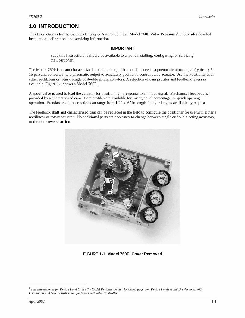
1.0 INTRODUCTION This Instruction is for the Siemens Energy & Automation, Inc. Model 760P Valve Positioner1. It provides detailed installation, calibration, and servicing information.
IMPORTANT
Save this Instruction. It should be available to anyone installing, configuring, or servicing the Positioner.
The Model 760P is a cam-characterized, double-acting positioner that accepts a pneumatic input signal (typically 3-15 psi) and converts it to a pneumatic output to accurately position a control valve actuator. Use the Positioner with either rectilinear or rotary, single or double acting actuators. A selection of cam profiles and feedback levers is available. Figure 1-1 shows a Model 760P. A spool valve is used to load the actuator for positioning in response to an input signal. Mechanical feedback is provided by a characterized cam. Cam profiles are available for linear, equal percentage, or quick opening operation. Standard rectilinear action can range from 1/2" to 6" in length. Longer lengths available by request. The feedback shaft and characterized cam can be replaced in the field to configure the positioner for use with either a rectilinear or rotary actuator. No additional parts are necessary to change between single or double acting actuators, or direct or reverse action.
FIGURE 1-1 Model 760P, Cover Removed
1 This Instruction is for Design Level C. See the Model Designation on a following page. For Design Levels A and B, refer to SD760, Installation And Service Instruction for Series 760 Valve Controller.

Introduction SD760-2
April 2002 1-2
1.1 SPECIFICATIONS
The two tables in this section contain the performance and environmental specifications for the Positioner. Table 1-1 contains the specifications and Table 1-2 lists the available options. Final Positioner specifications must consider any installed options. When an option is installed in a positioner and one or more of the option’s specifications are less stringent than the Positioner specifications, those specific option specifications must supersede Positioner specifications.
TABLE 1-1 Positioner Specifications
Parameter Specification
Temperature Range Standard: -40° to +85°C (-40° to +185°F) - When installing in a hazardous location, refer to Control Drawing 15032-7609 for temperature limitations. High Temperature: -29°C to 149°C (-20°F to +300° F); no electrical options.
Enclosure NEMA 4X per NEMA Standard 250 IP65 per IEC Standard 529
Connections Pneumatic - 1/4 NPT Gauge - 1/8 NPT Electrical - 1/2 NPT, - M20 (optional) Exhaust - 1/4 NPT
Finish Epoxy/Polyester powder coat
Output Configuration Single or double acting
Action Direct or reverse
Supply Pressure 150 psig max.
Air Consumption Standard Spool - 0.5 scfm (typical); High Flow Spool - 1 scfm (typical)
Flow Capacity Standard Spool 9 scfm (Cv = 0.3) @ 60 psig supply standard
Flow Capacity High Flow Spool 18 scfm (Cv = 0.6) @ 60 psig supply standard
Input Signal 3-15 psig, 3-27 psig Up to 50% split range
Feedback Signal 90° rotary standard; 1/2" to 6" (12.7 mm to 152.4 mm) rectilinear optional
Feedback Configuration Cam characterization
Pressure Gain 160 %/% @ 60 psig supply std. (800 psi/psi)
Span Adjustable -60 to +25% of normal span
Zero Adjustable -10 to +60% of normal span
Linearity (Independent) 0.5% of normal span (typical)
Hysteresis 0.75% of normal span (typical)
Deadband Less than 0.25% of span
Repeatability Within 0.5% valve travel
Supply Pressure Effect Less than 0.2% valve travel for a 5 psig change in supply pressure
Materials of Construction Stainless Steel, Aluminum, Brass, Nickel Plated Brass, Nickel Plated Steel, Polyphenylene Sulfide, Silicone, Silicone on Fiberglass, Neoprene on Nylon, Viton, Viton on Nomex, Epoxy Polyester Powder Coat, Glass Filled Nylon, Polycarbonate, Bronze, Steel, Gold

SD760-2 Introduction
April 2002 1-3
Parameter Specification
Electrical Classification FM Approval CSA Certification: CE
Intrinsically Safe, Entity: Class I, Div. 1, Groups A, B, C, and D Class II, Div. 1, Groups F and G Class III, Div. 1, when installed in accordance with Control Drawing 15032-7609 Non-Incendive: Class I, Div. 2, Groups A, B, C, and D Suitable for: Class II, Div. 2, Groups F and G Class III, Div. 2 Intrinsically Safe: Class I, Div. 1, Groups A, B, C, and D Class II, Div. 1, Groups E, F, and G Class III, Div. 1, when installed in accordance with Control Drawing 15032-7609 Suitable for: Class I, Div. 2, Groups A, B, C, and D Class II, Div. 2, Groups E, F, and G Class III, Div. 2 EN50081-1 and EN50081-2 Emission EN50082-1 and EN50082-2 Immunity

Introduction SD760-2
April 2002 1-4
TABLE 1-2 Option Specifications
All percentages are based on full span of output, unless otherwise noted.
Parameter ↓ Option → 4-20 mA Feedback 1K Ohm Potentiometer
Temperature Range -40° to +85°C (-40° to +185°F) Standard Temperature: -40° to +85°C (-40° to +185°F) High Temperature: -29° to +149°C (-20° to +300°F)
Configuration 4-20 mAdc output, direct or reverse acting
Resistive output, direct or reverse acting
Linearity Less than 1.0% Less than 1.0%
Hysteresis Less than 0.5% Less than 0.5%
Deadband Less than 0.25% Less than 0.25%
Repeatability Within 0.3% Within 0.3%
Supply voltage effect Less than 0.01% for 5V change in supply
-----
Ambient temperature effect Less than 1.0% per 28°C (50°F) change Less than 1.0% per 28°C (50°F) change
Zero / Span 55° to 150° input range for full span 0 to 915 Ohms over 90° input rotation
Power Requirements 10 to 36 Vdc -----
Power Rating ----- 1 Watt maximum
Parameter ↓ Option → Mechanical Limit Switches Proximity Sensors
Temperature Range -40° to +85°C (-40° to +185°F) -20° to +85°C (-4° to +185°F)
Configuration Two switches, infinite setpoint resolution
Two sensors, infinite setpoint resolution
Power Rating 10A@125/250 Vac, 10A@24 Vdc, 0.1A@125 Vdc
See barrier manufacturer instructions
Mechanical life 1 million cycles no load, 100,000 full load
Essentially infinite
Connections (per switch) Normally open, Normally closed, Common
See barrier manufacturer instructions
Repeatability Within 0.3% valve travel span Within 0.3% valve travel span
SD760-2 Introduction
April 2002 1-5
1.2 MODEL DESIGNATION
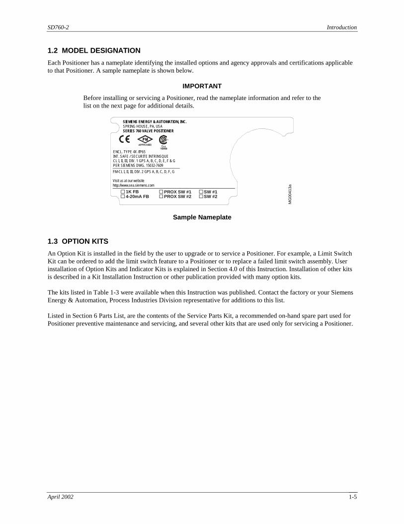
Each Positioner has a nameplate identifying the installed options and agency approvals and certifications applicable to that Positioner. A sample nameplate is shown below.
IMPORTANT
Before installing or servicing a Positioner, read the nameplate information and refer to the list on the next page for additional details.
R
SIE ME NS E NER GY & A UTO MAT ION , INC
SE RIE S 76 0 VA LVE CO NTR OLL ER
1K FB4-20mA FB
PROX SW #1PROX SW #2
FM -CL I, II, III, D IV. 2 GP S A , B, C , D, F, G
EN CL. TYP E 4X /IP6 5
IN T. SA FE / SE CUR ITE INTR INS QUE
CL I, II , III, DIV. 1 GP S A , B, C, D , E, F & G
PE R S IEME NS DWG . 15 032- 760 9
SW #1SW #2
Vis it u s at our w ebs ite:
htt p://w ww .sea .siem ens .com
SIEMENS ENERGY & AUTOMATION, INC.SPRING HOUSE, PA, USASERIES 760 VALVE POSITIONER
ENCL. TYPE 4X /IP65INT. SAFE / SECURITE INTRINSQUECL I, II, III, DIV. 1 GPS A, B, C, D, E, F & GPER SIEMENS DWG. 15032-7609FM-CL I, II, III, DIV. 2 GPS A, B, C, D, F, G
Visit us at our websitehttp://www.sea.siemens.com
MG
0041
3a
Sample Nameplate
1.3 OPTION KITS
An Option Kit is installed in the field by the user to upgrade or to service a Positioner. For example, a Limit Switch Kit can be ordered to add the limit switch feature to a Positioner or to replace a failed limit switch assembly. User installation of Option Kits and Indicator Kits is explained in Section 4.0 of this Instruction. Installation of other kits is described in a Kit Installation Instruction or other publication provided with many option kits. The kits listed in Table 1-3 were available when this Instruction was published. Contact the factory or your Siemens Energy & Automation, Process Industries Division representative for additions to this list. Listed in Section 6 Parts List, are the contents of the Service Parts Kit, a recommended on-hand spare part used for Positioner preventive maintenance and servicing, and several other kits that are used only for servicing a Positioner.
Introduction SD760-2
April 2002 1-6
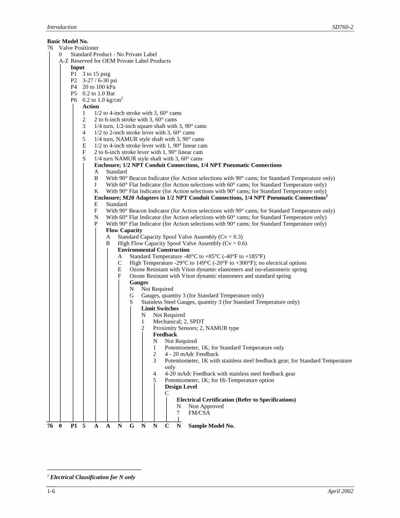
Basic Model No. 76 Valve Positioner 0 Standard Product - No Private Label
A-Z Reserved for OEM Private Label Products Input P1 3 to 15 psig P2 3-27 / 6-30 psi P4 20 to 100 kPa P5 0.2 to 1.0 Bar P6 0.2 to 1.0 kg/cm2 Action 1 1/2 to 4-inch stroke with 3, 60° cams 2 2 to 6-inch stroke with 3, 60° cams 3 1/4 turn, 1/2-inch square shaft with 3, 90° cams 4 1/2 to 2-inch stroke lever with 3, 60° cams 5 1/4 turn, NAMUR style shaft with 3, 90° cams E 1/2 to 4-inch stroke lever with 1, 90° linear cam F 2 to 6-inch stroke lever with 1, 90° linear cam S 1/4 turn NAMUR style shaft with 3, 60° cams Enclosure; 1/2 NPT Conduit Connections, 1/4 NPT Pneumatic Connections A Standard B With 90° Beacon Indicator (for Action selections with 90° cams; for Standard Temperature only) J With 60° Flat Indicator (for Action selections with 60° cams; for Standard Temperature only) K With 90° Flat Indicator (for Action selections with 90° cams; for Standard Temperature only) Enclosure; M20 Adapters in 1/2 NPT Conduit Connections, 1/4 NPT Pneumatic Connections2 E Standard F With 90° Beacon Indicator (for Action selections with 90° cams; for Standard Temperature only) N With 60° Flat Indicator (for Action selections with 60° cams; for Standard Temperature only) P With 90° Flat Indicator (for Action selections with 90° cams; for Standard Temperature only) Flow Capacity A Standard Capacity Spool Valve Assembly (Cv = 0.3) B High Flow Capacity Spool Valve Assembly (Cv = 0.6) Environmental Construction A Standard Temperature -40°C to +85°C (-40°F to +185°F) C High Temperature -29°C to 149°C (-20°F to +300°F); no electrical options E Ozone Resistant with Viton dynamic elastomers and iso-elastomeric spring F Ozone Resistant with Viton dynamic elastomers and standard spring Gauges N Not Required G Gauges, quantity 3 (for Standard Temperature only) S Stainless Steel Gauges, quantity 3 (for Standard Temperature only) Limit Switches N Not Required 1 Mechanical; 2, SPDT 2 Proximity Sensors; 2, NAMUR type Feedback N Not Required 1 Potentiometer, 1K; for Standard Temperature only
2 4 - 20 mAdc Feedback 3 Potentiometer, 1K with stainless steel feedback gear; for Standard Temperature
only 4 4-20 mAdc Feedback with stainless steel feedback gear 5 Potentiometer, 1K; for Hi-Temperature option
Design Level C Electrical Certification (Refer to Specifications) N Non Approved 7 FM/CSA 76 0 P1 5 A A N G N N C N Sample Model No.
2 Electrical Classification for N only

SD760-2 Introduction
April 2002 1-7
TABLE 1-3 Option and Service Kits Item Kit Description Part Number Bracket Kits 1 NAMUR Sealed Bracket, 45 x 80 mm, Rotary (NEMA 4 Bracket) 15822-550 2 Model 750 Adapter Plate Kit (see Section 4.5 Model 750 Adapter Plate) 16300-79 3 NAMUR Mounting Kit 55 x 80 mm, Rotary 16300-147 4 NAMUR Mounting Kit 55 x 130 mm, Rotary 16300-149 5 NAMUR Mounting Kit 75 x 130 mm, Rotary 16300-151 6 NAMUR Mounting Kit 45 x 80 mm, Rotary 16300-513 7 NAMUR Mounting Kit, Rectilinear 16300-516 Cam Kits (see Section 3 Calibration for installation) 1 Blank Cams Kit 16300-267 2 Rotary Action (set of 3 cams: linear, quick opening, and equal percentage) 16300-783 3 Linear Action (set of 3 cams: linear, quick opening, and equal percentage) 16300-784 Shaft and Lever Kits (see Section 4.4 Feedback Arm and Rotary Shaft Kits) 1 NAMUR 16300-690 2 0.5" x 0.5" Square Root 16300-693 3 0.65" x 0.65" Square Root 16300-694 4 0.25" to 2" Linear 16300-695 5 0.25" to 4" Linear 16300-696 6 3" to 6" Linear 16300-697 7 Hi-Performance NAMUR with/anti-backlash 16300-699 Indicator Kits (see Section 4.2 Indicator Kits for installation) 1 Flat Indicator, Lever 16300-1244 2 Flat Indicator, 1/4 Turn 16300-1245 3 Beacon Indicator 16300-1246 4 Lens Kit, 75 Degree Flat Indicator 16300-919 Input Kits 1 3-27 psi Input, Standard Temperature 16300-771 2 3-27 psi Input, Hi-Temperature 16300-772 Flow Output Kits (see Section 5 Maintenance for installation) 1 Standard Flow Output Kit 16300-1241 2 High Flow Output Kit 16300-1242 Option Kits (see Section 4 Option Kits for installation) 1 Limit Switch Kit 16300-500 2 Proximity Switch Kit 16300-501 3 4-20 mA Feedback Kit 16300-502 4 1K Ohm Feedback Potentiometer 16300-503 5 Limit Switch and 4-20 mA DC Feedback 16300-504 6 Limit Switch and 1K Ohm Feedback Potentiometer 16300-505 7 Proximity Switch and 4-20 mA DC Feedback 16300-506 8 Proximity Switch and 1K Ohm Feedback Potentiometer 16300-507 9 4-20 mA Feedback Kit, Stainless Steel Gear 16300-577 10 Limit Switch and 4-20 mA DC Feedback, Stainless Steel Gear 16300-578 11 Proximity Switch and 4-20 mA DC Feedback, Stainless Steel Gear 16300-579 12 1K Ohm Feedback Potentiometer, Stainless Steel Gear 16300-580
Introduction SD760-2
April 2002 1-8
Item Kit Description Part Number 13 Limit Switch and 1K Ohm Feedback Potentiometer, Stainless Steel Gear 16300-581 14 Proximity Switch and 1K Ohm Feedback Potentiometer, Stainless Steel Gear 16300-582 Spare Parts Kits 1 Spare Parts Kit (see Section 6 Parts List for contents) 16300-1249 Other Kits 1 Exhaust Vent Assembly 16300-203 2 Pipe Adapter, 1/2 NPT Male to M20 x 1.5 Female 16300-936 3 Gauges Kit 16300-1240 5 High Temperature Conversion Kit 16300-1248
1.4 PRODUCT SUPPORT
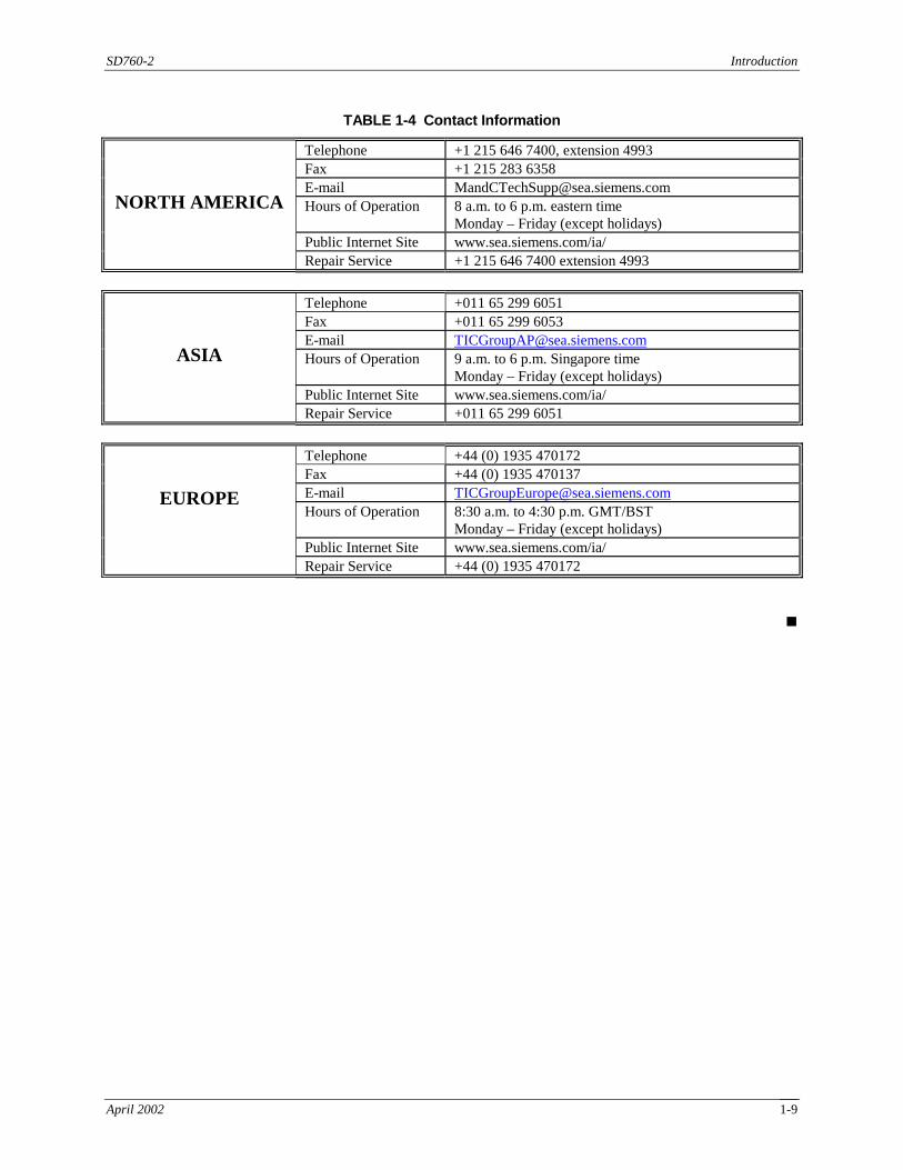
Product support can be obtained from a customer service center (i.e. Technical Support Group in North America or a Technical Information Center (TIC) in Asia and Europe). Each region has a customer service center that provides direct telephone support on technical issues related to the functionality, application, and integration of all products supplied by the Process Industries Division of Siemens Energy & Automation. Regional contact information is provided below. Your regional customer service center is the first place to call when seeking product support information. When calling, it is helpful to have the following information ready:
• Product part number or model number and version
• If there is a problem with product operation: - Whether or not the problem is intermittent - The steps performed before the problem occurred - The steps that have been taken following the appearance of the problem - Any status message, error messages, or LED indications displayed - Installation environment
SD760-2 Introduction
April 2002 1-9
TABLE 1-4 Contact Information
Telephone +1 215 646 7400, extension 4993 Fax +1 215 283 6358 E-mail [email protected] Hours of Operation 8 a.m. to 6 p.m. eastern time
Monday – Friday (except holidays) Public Internet Site www.sea.siemens.com/ia/
NORTH AMERICA
Repair Service +1 215 646 7400 extension 4993
Telephone +011 65 299 6051 Fax +011 65 299 6053 E-mail [email protected] Hours of Operation 9 a.m. to 6 p.m. Singapore time
Monday – Friday (except holidays) Public Internet Site www.sea.siemens.com/ia/
ASIA
Repair Service +011 65 299 6051
Telephone +44 (0) 1935 470172 Fax +44 (0) 1935 470137 E-mail [email protected] Hours of Operation 8:30 a.m. to 4:30 p.m. GMT/BST
Monday – Friday (except holidays) Public Internet Site www.sea.siemens.com/ia/
EUROPE
Repair Service +44 (0) 1935 470172
!

Introduction SD760-2
April 2002 1-10

SD760-2 Installation
April 2002 2-1
2.0 INSTALLATION This section describes installation of the Positioner. The field installation of options is described in Section 4 Option Kits and in publications supplied with the individual kits. In most instances, option kits should be installed in the Positioner before the Positioner is installed. Operating temperature limits for the Positioner and its options are stated in Section 1.1 Specifications. The temperature in the selected location must not exceed the specified operating temperatures. Be sure to consider the environmental specifications of the Positioner and any installed options. The Positioner will need to be calibrated before being put into service.
2.1 SHIPPING AND STORAGE
If the positioner is to be stocked, stored, or shipped to another location prior to piping, the factory installed plastic plugs must be inserted in all otherwise unterminated pneumatic ports and both conduit connector holes to prevent entry of moisture, dirt, or other contaminant.
2.2 MECHANICAL INSTALLATION
Refer to Figure 2-1 for physical dimensions and the location of the input shaft, mounting holes, and pneumatic ports. This figure also locates the two conduit connections for electrical wiring. The selection of indicator options will affect Positioner dimensions. When determining a mounting method, location, and orientation, ensure that the:
• Positioner and actuator mounting brackets are considered. A Positioner mounting bracket (NAMUR or other style) can be ordered separately. A custom Positioner bracket can be ordered or fabricated by the user. There are three sets of Positioner mounting holes, as shown in Figure 2-1. Refer to the actuator manufacturer’s literature for mounting information.
• Input shaft is accessible and there is sufficient space for movement of the Positioner-to-actuator coupling mechanism
• Pneumatic ports are accessible and there is piping access
• Electrical conduit connections are accessible and there is sufficient space for electrical conduit
• Environmental specifications of the Positioner and any options are not exceeded
CAUTION
Exceeding the specified operating temperature limits can adversely affect performance and safety, and may cause damage to the Positioner.
To mechanically install the Positioner perform the following steps.
1. Remove the Positioner cover and note the installed cam type and cam lobe (CW or CCW) against the cam follower. A linear cam is installed at the factory unless otherwise specified on the order. If the cam type or cam lobe is to be changed, go to Section 3.2 Cam Installation And Indexing. Then return to this section, step 2.
2. As necessary, loosen the cam lock screw so that the feedback shaft mechanism can be aligned. As needed, refer to Section 3.2 Cam Installation And Indexing and Figure 3-1 for details.
3. Install the Positioner cover. Install a feedback connection between positioner and actuator. Refer to either A or B below depending upon type of actuator to be used.
Installation SD760-2
April 2002 2-2
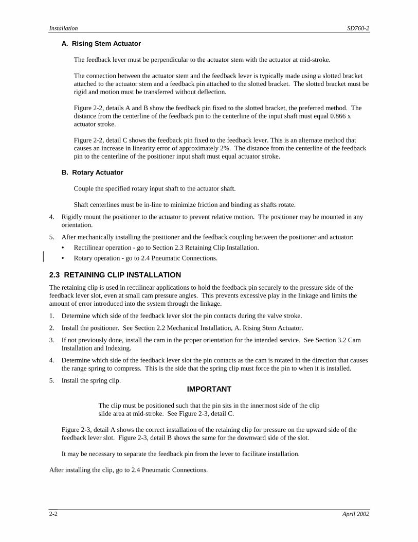
A. Rising Stem Actuator The feedback lever must be perpendicular to the actuator stem with the actuator at mid-stroke. The connection between the actuator stem and the feedback lever is typically made using a slotted bracket
attached to the actuator stem and a feedback pin attached to the slotted bracket. The slotted bracket must be rigid and motion must be transferred without deflection.
Figure 2-2, details A and B show the feedback pin fixed to the slotted bracket, the preferred method. The
distance from the centerline of the feedback pin to the centerline of the input shaft must equal 0.866 x actuator stroke.
Figure 2-2, detail C shows the feedback pin fixed to the feedback lever. This is an alternate method that
causes an increase in linearity error of approximately 2%. The distance from the centerline of the feedback pin to the centerline of the positioner input shaft must equal actuator stroke.
B. Rotary Actuator
Couple the specified rotary input shaft to the actuator shaft. Shaft centerlines must be in-line to minimize friction and binding as shafts rotate.
4. Rigidly mount the positioner to the actuator to prevent relative motion. The positioner may be mounted in any orientation.
5. After mechanically installing the positioner and the feedback coupling between the positioner and actuator:
• Rectilinear operation - go to Section 2.3 Retaining Clip Installation.
• Rotary operation - go to 2.4 Pneumatic Connections.
2.3 RETAINING CLIP INSTALLATION
The retaining clip is used in rectilinear applications to hold the feedback pin securely to the pressure side of the feedback lever slot, even at small cam pressure angles. This prevents excessive play in the linkage and limits the amount of error introduced into the system through the linkage.
1. Determine which side of the feedback lever slot the pin contacts during the valve stroke.
2. Install the positioner. See Section 2.2 Mechanical Installation, A. Rising Stem Actuator.
3. If not previously done, install the cam in the proper orientation for the intended service. See Section 3.2 Cam Installation and Indexing.
4. Determine which side of the feedback lever slot the pin contacts as the cam is rotated in the direction that causes the range spring to compress. This is the side that the spring clip must force the pin to when it is installed.
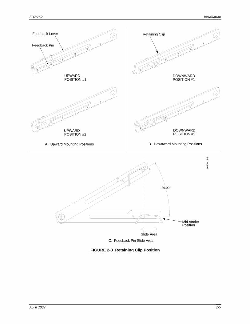
5. Install the spring clip. IMPORTANT
The clip must be positioned such that the pin sits in the innermost side of the clip slide area at mid-stroke. See Figure 2-3, detail C.
Figure 2-3, detail A shows the correct installation of the retaining clip for pressure on the upward side of the feedback lever slot. Figure 2-3, detail B shows the same for the downward side of the slot.
It may be necessary to separate the feedback pin from the lever to facilitate installation.
After installing the clip, go to 2.4 Pneumatic Connections.

SD760-2 Installation
April 2002 2-3
6.27 (159.3)6.56 (166.6)
6.88 (174.8)
6.11(155.2)
6.43(163.3)
Front View1/2 NPT ElectricalConduit Connections
Input Shaft ForRectilinear Application
Dimensions are in inches (millimeters)Dimension "A" = 0.696 (17.68)Dimension "B" Standard Lever = 2.00 (50.8), 4.00 (101.6), or 6.00 (152.4)
B
1/4-200.4 (10.16) Deep4 places
A A
AA
3.35
(85.
09)
2.00
(50.
8)
3.44
(87.
38)
2.00
(50.
8)
2.20(55.88)
1.95(49.53)
1.95(49.53)
3.25(82.55)
Back View
NEMA 4XVent
2.91(73.9)
0.33(8.4)
M6 x 1, 4 Holes0.31 Deep;Bolt Circle1.968 (50.00)
1/4-200.30 (7.62) Deep
NAMUR InputShaft For RotaryApplication(Others Available)
Rotary Application
2.43(61.7)
3.77(95.8)
1.39(35.3)
1.10(27.9)
Valve 1 Supply Exhaust Valve 2 1/4 NPT (Typical) Right View
MG
0040
4d
Rectilinear Application
1/4-200.4 (10.16) Deep2 places
Available Low ProfileFlat Indicator
Bottom View0.56 (14.2),Optional1.03 (26.2)
Input1/4 NPT
FIGURE 2-1 Installation Dimensions

Installation SD760-2
April 2002 2-4
Actuator
Positioner
Actuator Stem
Slotted Bracket
Feedback Pin
Feedback Lever
76-1
263r
2
Equal to 0.866 x Strokeat Mid-Stroke
B. Preferred Method of Stroke Setting for Feedback Pin Connection. Feedback Lever Shown at Mid-Stroke.
Feedback Lever
Slotted Bracket
Input Shaft
Equal to Stroke
C. Method of Connecting Feedback Pin and Stroke Setting
A. Controller Mounting and Preferred Method of Connecting Feedback Pin
FIGURE 2-2 Positioner Mounting and Feedback Pin Connection
SD760-2 Installation
April 2002 2-5
C. Feedback Pin Slide Area
Slide Area
Mid-strokePosition
30.00°
Feedback Lever
UPWARDPOSITION #1
Feedback Pin
Retaining Clip
DOWNWARDPOSITION #1
A. Upward Mounting Positions
UPWARDPOSITION #2
B. Downward Mounting Positions
DOWNWARDPOSITION #2
1630
0-12
r2
FIGURE 2-3 Retaining Clip Position

Installation SD760-2
April 2002 2-6
2.4 PNEUMATIC CONNECTIONS
Pneumatic connection ports are shown in Figure 2-1 and listed below. Each port is identified on the Positioner.
Port Connection
V2 Output to actuator; pressure in V2 increases with increasing input signal S Supply pressure to system
V1 Output to actuator; pressure in V1 decreases with increasing input signal E Exhaust port; can be piped away from positioner. DO NOT PLUG I Input port
WARNING
Plugging or applying pressure to the Exhaust port will damage the unit and may cause personal injury.
Pressure in excess of 150 psi in a V1, V2, or Supply port may damage the Positioner and may cause personal injury.
Supply pressure to the Positioner must not exceed actuator maximum pressure rating.
Input pressure in excess of 35 psi may cause the input gauge to go out of calibration. Pressure of 120 psi may cause the gauge to burst.
Refer to Table 2-1 and the actuator manufacturer’s literature to determine the required pneumatic connections between the Positioner and the actuator.
TABLE 2-1 Positioner-To-Actuator Pneumatic Connections
ACTUATOR TYPE
POSITIONER ACTION CONNECTIONS
Single acting Direct acting (output increases with increasing input signal)
Connect V2 and plug V1
Single acting Reverse acting (output decreases with increasing input signal)
Connect V1 and plug V2
Double acting --- 1. Note actuator position desired for minimum input signal to positioner.
2. Connect V2 to actuator port that causes actuator to move away from position noted in above step.
3. Connect V1 to remaining port.
2.4.1 Piping
All pneumatic connections are 1/4 NPT (1/8 NPT for gauges). User supplied materials:
• Scale free piping at least 1/8" ID for standard flow models and 1/4" ID for high flow models.
• 1/4 NPT pipe fitting for each connection. Tighten fittings to 12 ft-lb. (16.3 Nm) maximum. Do not over-tighten fittings.

SD760-2 Installation
April 2002 2-7
• 1/4 NPT pipe plug to plug the unused port for single acting actuators. Piping recommendations:
• Blow out all piping before connections are made to prevent dirt, chips, or debris from entering the positioner.
• Use pipe sealant sparingly and only on male threads. A non-hardening sealant is strongly recommended. Note that pipe sealing tape is not recommended.
• Connect the positioner to a source of clean, oil-free instrument air. Instrument air requirements are given in the following section. Failure to do so will increase the possibility of a malfunction or deviation from specified performance.
After piping the Positioner, go to Section 2.5 Electrical Connections.
2.4.2 Instrument Air Requirements
Instrument quality air must be supplied to the Positioner.
CAUTION
Synthetic compressor lubricants in the instrument air may cause deterioration of some positioner components resulting in positioner failure.
There are many types of synthetic lubricants. Some may not be compatible with the materials used in the construction of the positioner. Wetting of these materials by such an oil mist or vapor may cause them to deteriorate. This can result in failure of the positioner. A list of materials used in the positioner is found in Section 1.2 Specifications. Requirements for a quality instrument air supply can be found in "Quality Standard for Instrument Air" (ISA-S7.3) by the Instrument Society of America. Basically this standard calls for the following.
Particle Size - The maximum particle size in the air stream at the instrument should be no larger than 3 microns. Dew Point - the dew point, at line pressure, should be at least 10°C (18°F) below the minimum temperature to which any part of the instrument air system is exposed at any season of the year. Under no circumstances should the dew point, at line pressure, exceed 2°C (35.6°F). Oil Content - The maximum total oil or hydrocarbon content, exclusive of non-condensables, should not exceed 1 ppm under normal operating conditions.

Installation SD760-2
April 2002 2-8
2.5 ELECTRICAL CONNECTIONS
Route the electrical wiring to the Positioner through user-supplied conduit that is connected to one or both of the conduit connections on the positioner enclosure.
WARNING
Electrical shock hazard Explosion hazard
Can cause death or injury
• Remove power from all wires and terminals before working on equipment.
• In potentially hazardous atmosphere, remove power from equipment before connecting or disconnecting power, signal, or other circuit.
• Observe all pertinent regulations regarding installation in hazardous area.
2.5.1 Non-Hazardous Locations
An installation in a non-hazardous location should be in accordance with the current editions of applicable National and all Local Electrical Codes. Wiring for options is described in Section 4 Option Kits. CE Approved See Table 1-1 Positioner Specifications and the Declaration of Conformity at back of Section 9. Shielded cable is required.
2.5.2 Hazardous Locations
An installation in a hazardous location must be in accordance with the current editions of applicable National and Local Electrical Codes. Wiring for options is described in Section 4 Option Kits. For installation in hazardous locations the Positioner or Positioner Modules (Options) must display the following: The NEC or CEC hazardous location(s) for which the equipment is approved The FM or CSA logo Hazardous location classifications appropriate to the installation Before installing a positioner in a hazardous location, review the FM entity parameters and select, as needed, energy limiting barriers. When electrically installing a Positioner in a hazardous area, refer to control drawing 15032-7609 in Section 9 of this Instruction. A typical system consists of a Positioner installed in a hazardous area, energy limiting barriers installed in a non-hazardous location, and interconnecting shielded, twisted-pair wiring.

SD760-2 Installation
April 2002 2-9
WARNING
Electrical shock hazard Explosion hazard
Can cause death or injury
• Modifications to the Positioner or installation of non-approved options will void the electrical approval.
• Observe all pertinent regulations regarding installation in hazardous area.
FM and CSA Hazardous Location Precautions This section provides FM/CSA hazardous locations precautions that should be observed by the user when installing or servicing the equipment described in this manual. Precautions - English For Division 1 and Division 2 hazardous locations:
WARNING
Explosion hazard Explosion can cause death or serious injury. Substitution of components may impair intrinsic safety. All pertinent regulations regarding installation in a hazardous area must be observed.
When the equipment described in this manual is installed without safety barriers, the following precautions should be observed. Switch off the power at its source (in non-hazardous location) before connecting or disconnecting power, signal or other wiring. Précautions - Français Emplacements dangereux de Division 1
AVERTISSEMENT
LA SUBSTITUTION DE COMPOSANTS PEUT COMPROMETTRE LA SÉCURITÉ INTRINSÈQUE
Emplacements dangereux de Division 2
AVERTISSEMENT
RISQUE D’EXPLOSION - LA SUBSTITUTION DE COMPOSANTS PEUT RENDRE CE MATÉRIEL INACCEPTABLE POUR LES EMPLACEMENTS DE CLASSE I, DIVISION 2

Installation SD760-2
April 2002 2-10
Lorsque l’appareil décrit dans la notice ci-jointe est installé sans barrières de sécurité, on doit couper l’alimentation électrique a la source (hors de l’emplacement dangereux) avant d’effectuer les opérations suivantes branchement ou débranchement d’un circuit de puissance, de signalisation ou autre.
2.5.3 Hazardous Location Installations
Perform the following steps to install the Positioner in a hazardous location. Note that barriers may not be needed in an installation. 1. Install the Positioner as detailed in the preceding sections. 2. Install energy limiting barriers in the non-hazardous area. Refer to the barrier manufacturer's instructions and to
the appropriate connection diagram in the control drawing found in the back of this manual. 3. Install conduit for wiring to the Positioner. Install pull boxes as needed and remove burrs and sharp edges from
conduit tubing. 4. Install wiring between Positioner and barriers per the control drawing found in the back of this manual. Ground
the Positioner body. Ground screws are provided on the bottom of the Positioner and inside the enclosure; each is adjacent to a ground symbol. A barrier must be grounded and the resistance to ground must not exceed 1 ohm.
5. Install wiring between barriers and output terminals of the Positioner driving device. 6. Check all signal and ground connections before applying power. 7. Proceed to Section 3 Calibration.
!

SD760-2 Calibration
April 2002 3-1
3.0 CALIBRATION Calibrate a positioner before placing it in service, after field installing an Output Option Kit, and after repair.
3.1 EQUIPMENT NEEDED
TABLE 3-1 Calibration Equipment
ITEM QUANTITY
Pressure regulator, adjustable from 0 to 30 psig, 760P only 1
Test gauge, 0 to 30 psig 1
Small slotted screwdriver 1
3.2 CAM INSTALLATION AND INDEXING
A Model 760 is shipped with the linear cam installed unless otherwise specified on the order. Use this section to install another cam or change the cam lobe. Mount the Positioner before proceeding with this section of the Instruction.
INDEXING OF CW CAM INDEXING OF CCW CAM
CAM LOCKINGSCREW
CAM LOCKINGNUT
CAM FOLLOWERBEARING
INPUT SHAFT
UPPER CAM INDEX
LOWER CAM INDEX
CAM
760-
117b
0%
50%
100%
0%
50%
100%
FIGURE 3-1 Cam Related Components and Indexing of CW and CCW Cams

Calibration SD760-2
April 2002 3-2
3.2.1 Cam Identification
Three standard cam profiles are available. An alphabetic designation, “LIN”, “EP”, or “QO”, appears on a cam to identify the cam lobe profile [i.e., (LIN) linear, (EP) modified equal percentage, or (QO) quick opening]. The letters CW or CCW denote the lobe of the cam to be used depending on feedback shaft rotation for increasing input signal. Figure 3-2 shows the standard cam characteristics.
100
100
80
80
60
60
40
40
20
200
0
% V
alve
Mot
ion
(0%
= M
inim
um A
ctua
tor
Pre
ssur
e)
% Input Signal (Direct Acting, Scale Reversed if Reverse Acting)
Linear
EqualPercentage
QuickOpening
MG
0040
5b
FIGURE 3-2 Standard Cam Characteristics
NOTE
The cam is designed to allow 10% over/under-range (negative 9 degrees). However, if under range is used, the zero and span will be slightly interactive.
3.2.2 Installing and Indexing a Cam
Refer to Figures 3-1 and 6-1 for cam and associated hardware identification. Depending upon the situation at hand (e.g. initial installation or post installation) some of the following steps may not need to be performed.
1. If the Positioner is installed, remove supply pressure from the Positioner.
CAUTION
Pinch hazard exists if supply pressure is not removed from the Positioner.
SD760-2 Calibration
April 2002 3-3
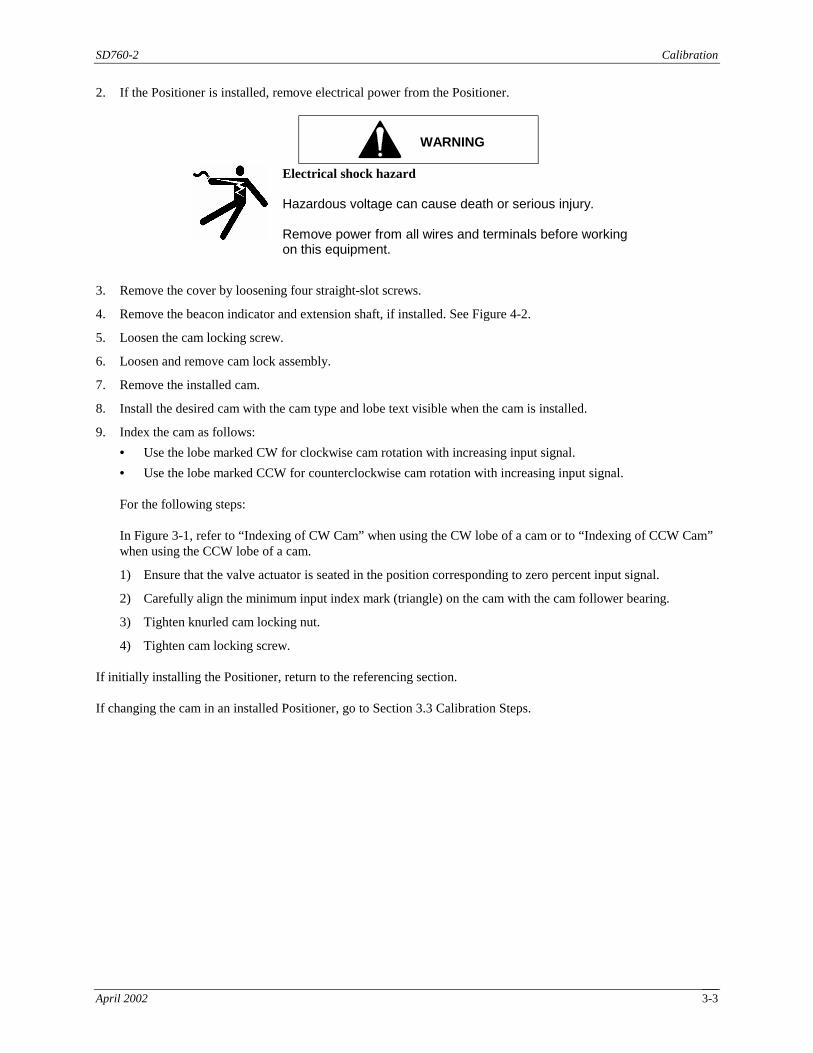
2. If the Positioner is installed, remove electrical power from the Positioner.
WARNING
Electrical shock hazard Hazardous voltage can cause death or serious injury. Remove power from all wires and terminals before working on this equipment.
3. Remove the cover by loosening four straight-slot screws.
4. Remove the beacon indicator and extension shaft, if installed. See Figure 4-2.
5. Loosen the cam locking screw.
6. Loosen and remove cam lock assembly.
7. Remove the installed cam.
8. Install the desired cam with the cam type and lobe text visible when the cam is installed.
9. Index the cam as follows:
• Use the lobe marked CW for clockwise cam rotation with increasing input signal.
• Use the lobe marked CCW for counterclockwise cam rotation with increasing input signal. For the following steps: In Figure 3-1, refer to “Indexing of CW Cam” when using the CW lobe of a cam or to “Indexing of CCW Cam” when using the CCW lobe of a cam.
1) Ensure that the valve actuator is seated in the position corresponding to zero percent input signal.
2) Carefully align the minimum input index mark (triangle) on the cam with the cam follower bearing.
3) Tighten knurled cam locking nut.
4) Tighten cam locking screw. If initially installing the Positioner, return to the referencing section. If changing the cam in an installed Positioner, go to Section 3.3 Calibration Steps.
Calibration SD760-2
April 2002 3-4
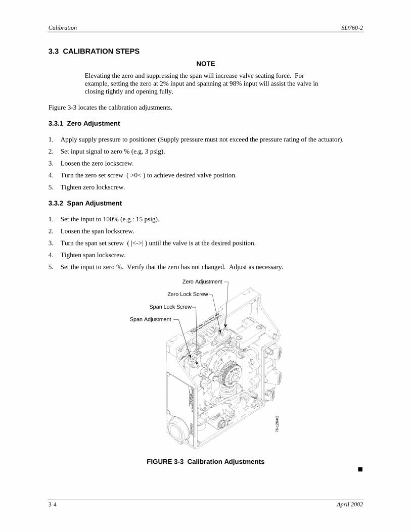
3.3 CALIBRATION STEPS
NOTE
Elevating the zero and suppressing the span will increase valve seating force. For example, setting the zero at 2% input and spanning at 98% input will assist the valve in closing tightly and opening fully.
Figure 3-3 locates the calibration adjustments.
3.3.1 Zero Adjustment
1. Apply supply pressure to positioner (Supply pressure must not exceed the pressure rating of the actuator).
2. Set input signal to zero % (e.g. 3 psig).
3. Loosen the zero lockscrew.
4. Turn the zero set screw ( >0< ) to achieve desired valve position.
5. Tighten zero lockscrew.
3.3.2 Span Adjustment
1. Set the input to 100% (e.g.: 15 psig).
2. Loosen the span lockscrew.
3. Turn the span set screw ( |<->| ) until the valve is at the desired position.
4. Tighten span lockscrew.
5. Set the input to zero %. Verify that the zero has not changed. Adjust as necessary.
Zero Adjustment
Zero Lock Screw
Span Lock Screw
Span Adjustment
76-1
264r
2
FIGURE 3-3 Calibration Adjustments !

SD760-2 Options
April 2002 4-1
4.0 OPTION KITS Locate the option kit to be installed in the following table, in the “Option Kit” column. Refer to the “Go To Section” column for an installation procedure for that kit. Important: Calibrate the Positioner before installing a kit; refer to Section 3 Calibration.
Option Kit Go To Section
Mechanical Limit Switches and Proximity Sensors
4-20 mAdc Current Feedback Option
1K Potentiometer Feedback Option
4.1 PC Board-Based Option Kits
Beacon and Flat Indicator Kits 4.2 Indicators Kits
Flow Output (Spool) Kits 4.3 Flow Output (Spool) Kits
Feedback Arm and Rotary Shaft Kits 4.4 Feedback Arm and Rotary Shaft Kits
750 Adapter Plate 4.5 Model 750 Adapter Plate
An exploded view of the Positioner is located in Section 6 Parts List.
4.1 PC BOARD-BASED OPTION KITS
This section provides field-installation details for the following option kits.
• Mechanical Limit Switches and Proximity Sensors
• 4-20 mAdc Current Feedback Option
• 1K Potentiometer Feedback Option
CAUTION
The temperature in the operating location must not exceed the temperature range stated in Table 1-2 Option Specifications.
For installation in hazardous a location, refer to Control Drawing 15032-7609 in Section 9 at the back of this Instruction.
NOTE
The positioner cam must be properly indexed and the unit calibrated before proceeding. Refer to Section 3 Calibration.
Circuit Board Handling Electrostatic discharge can damage semiconductor devices. A properly grounded conductive wrist strap must be worn whenever a circuit board assembly is handled or touched. A service kit with a wrist strap and static dissipative mat is available from Siemens (PN 15545-110). Equivalent kits are available from both mail order and local electronics supply companies.

Options SD760-2
April 2002 4-2
Equipment Needed
Common hand tools Torque wrench [18 in-lb (2 Nm)] Service Kit (described in the preceding paragraph)
4.1.1 Installation
The above options use a common circuit board platform, however, the electrical components on the board are determined by the individual option(s). The PC board is held in place by three 8-32 x 1/4" screws, mounted to hex standoffs. To install the board:
1. Remove supply pressure from the Positioner. Remove electrical power from the Positioner.
WARNING
Electrical shock hazard Hazardous voltage can cause death or serious injury. Remove power from all wires and terminals before working on this equipment.
2. Fasten a grounded wrist strap on your wrist to protect sensitive semiconductor devices from electrostatic discharge.
3. Get three standoffs from the kit. Insert and tighten the three standoffs (two long, one short) into the three bosses as shown in Figure 4-1. Figure 4-2 shows the installed Potentiometer Option. Tighten the standoffs to 18 in-lb (2 Nm).
Option Board
Long Standoff
Long Standoff
Short Standoff
76-1
266r
2
FIGURE 4-1 Option Board Installation

SD760-2 Options
April 2002 4-3
4. 4-20 mA and 1K potentiometer feedback option kits only - On the option board from the kit, loosen the two mounting screws securing the potentiometer bracket and rotate the bracket counterclockwise (see Figure 4-6). This provides clearance while installing the board.
5. Tighten the captive screws to fasten the option board from the kit to the three standoffs.
6. If the board includes either of the limit switch options, install the extension shaft and compression washer. Refer to Figures 4-2 and 6-1 and place the compression washer on the 1/4-20 threads of the input shaft. Install and tighten the extension shaft until the compression washer is completely flat. Tighten the shaft to 15 in-lb (1.7 Nm). Install two limit switch actuator cams; see Figure 4-2. For each actuator cam, pinch together the two tabs and slide the actuator cam onto the extension shaft until it aligns with a limit switch.
7. Go to Section 4.1.2 Electrical Connections. Locate the steps for the option kit being installed.
COMPRESSIONWASHER
EXTENSIONSHAFT
LIMIT SWITCHACTUATOR CAMS
LIMITSWITCHES
FIGURE 4-2 Mechanical Limit Switches
4.1.2 Electrical Connections
Refer to Section 2.5 for installation in hazardous locations. All wiring must be in accordance with applicable national and local electric codes for the intended electrical circuit load. Calibrate the 4-20 mA Feedback option or voltage feedback option before electrical connections are made. Go to Section 4.1.3 Calibration and then return to this section to make the electrical connections.
WARNING
Electrical shock hazard Hazardous voltage can cause death or serious injury. Remove power from all wires and terminals before working on this equipment.

Options SD760-2
April 2002 4-4
4.1.2.1 Mechanical Limit Switches and Proximity Sensors
Switch connections for the mechanical limit switches and the proximity sensors are located on a six-terminal block. The terminal connections are labeled as shown in Table 4-1.
TABLE 4-1 Limit Switch Terminal Block Connections
Terminal Mechanical Switches Proximity Sensors 1 Lower Switch N.C. (normally closed) Lower Sensor “+” 2 Lower Switch N.O. (normally open) --- Not Used --- 3 Lower Switch Com (common) Lower Sensor “-” 4 Upper Switch N.C. Upper Sensor “+” 5 Upper Switch N.O. --- Not Used --- 6 Upper Switch Com Upper Sensor “-”
Mechanical Limit Switches The mechanical limit switches are rated for 10A @ 125/250 Vac, 10A @ 24 Vdc, 0.1A @ 125 Vdc. Proximity Sensors
CAUTION
The proximity sensors are not intended to carry a load current - DO NOT WIRE SENSORS DIRECTLY TO ASSOCIATED APPARATUS.
The proximity sensors must be used in conjunction with a switch transfer barrier. The barrier provides either dual transistor outputs or dual relay outputs depending on the model. In order to comply with intrinsic safety approvals, the Pepperl + Fuchs ® proximity switches must be used with an approved Pepperl + Fuchs ® switch transfer barrier. Refer to the Model 760 Control Drawing, 15032-7609 in Section 9, for recommended approved barriers, specifications and wiring installation diagrams. Follow instructions supplied with the barrier for correct wiring of the Proximity Sensors to the barrier.
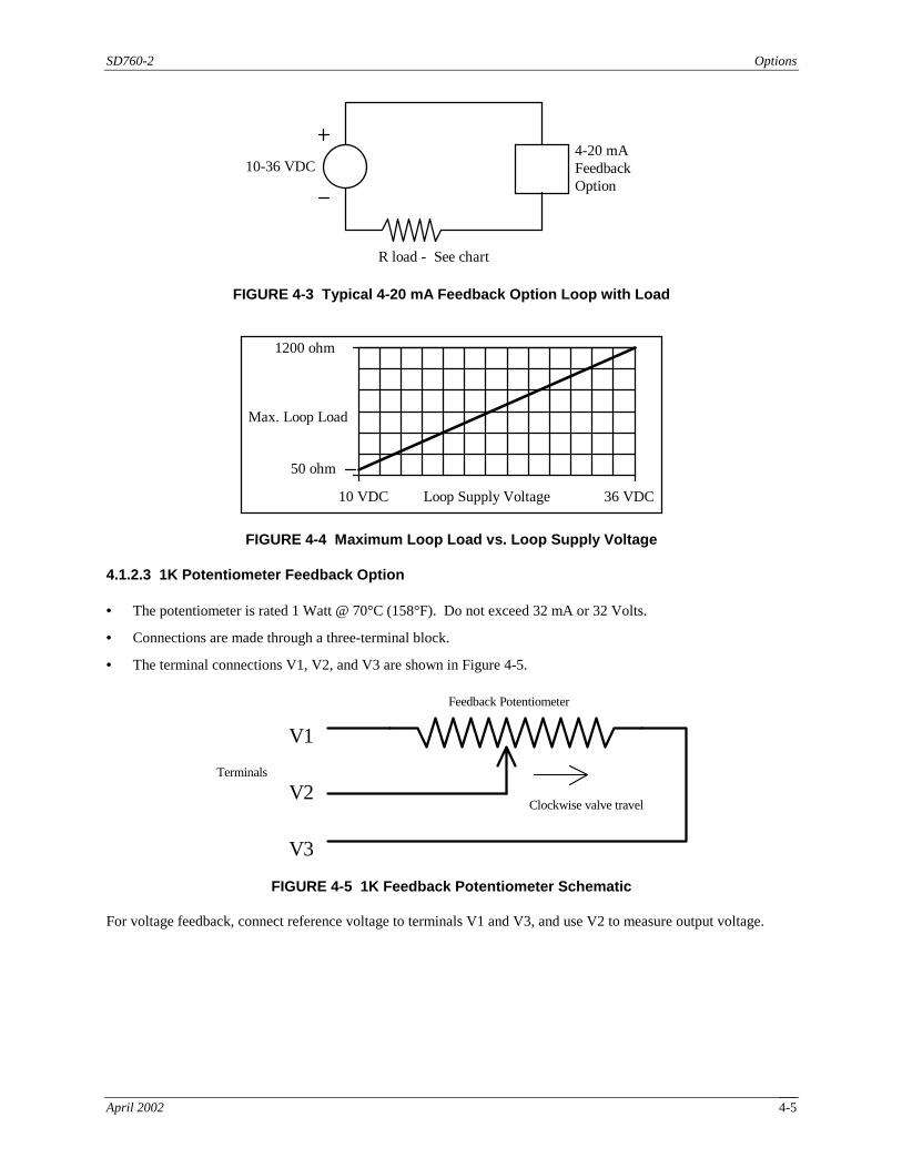
4.1.2.2 4-20 mAdc Current Feedback Board Option
Connect the power supply and load to the three-terminal block on the PC board as shown in Figure 4-3. The terminals labeled V1 and V2 are used for the 4-20 mA loop; V3 is not used. Polarity is not important. Recommended wiring is twisted shielded pairs, 22 AWG (0.38 mm2) or larger. The user-supplied DC loop power supply must furnish 10-36 Vdc at the required load current. See Figure 4-4 for a maximum loop load based on supply voltage. Refer to Control Drawing 15032-7609 for installation in hazardous locations.
SD760-2 Options
April 2002 4-5
R load - See chart
10-36 VDC4-20 mAFeedbackOption
FIGURE 4-3 Typical 4-20 mA Feedback Option Loop with Load
1200 ohm
50 ohm
10 VDC 36 VDCLoop Supply Voltage
Max. Loop Load
FIGURE 4-4 Maximum Loop Load vs. Loop Supply Voltage
4.1.2.3 1K Potentiometer Feedback Option
• The potentiometer is rated 1 Watt @ 70°C (158°F). Do not exceed 32 mA or 32 Volts.
• Connections are made through a three-terminal block.
• The terminal connections V1, V2, and V3 are shown in Figure 4-5.
V1
V3
V2 Clockwise valve travel
Feedback Potentiometer
Terminals
FIGURE 4-5 1K Feedback Potentiometer Schematic
For voltage feedback, connect reference voltage to terminals V1 and V3, and use V2 to measure output voltage.

Options SD760-2
April 2002 4-6
4.1.3 Calibration
This section describes calibration of:
• Mechanical Limit Switches and Proximity Sensors
• 4-20 mAdc Current Feedback Option
• 1K Potentiometer Feedback Option
4.1.3.1 Mechanical Limit Switches and Proximity Sensors
Install the board with the switches as described in the preceding sections.
1. Set the valve and actuator to the first desired limit position.
2. Squeeze the tabs on one of the cams, and rotate in the direction of valve rotation until the switch triggers.
3. Set valve and actuator at second desired limit position.
4. Squeeze the tabs on the second cam, and rotate in the direction of valve rotation until the switch triggers.
4.1.3.2 4-20 mAdc Current Feedback Board Option
Equipment needed.
TABLE 4-2 Equipment Needed for 4-20 mAdc Current Feedback Option
Item Quantity Ammeter 1 Jeweler’s Screwdriver 1 Small Slotted Screwdriver 1
1. Set actuator and valve to 50% +/- 5%. The potentiometer is a continuous turn potentiometer without end stops so it cannot be damaged by rotating past the end of its range.
2. Loosen, but do not remove, the potentiometer bracket screws. Swing the potentiometer away from the input gear, and rotate the potentiometer gear until the alignment mark is aligned with the input gear. See Figure 4-6.
3. Mesh gears lightly to eliminate backlash and tighten both of the bracket mounting screws. The red alignment mark should mesh within two gear teeth of the centerline of the gears as shown in Figure 4-6.
4. The 4-20 mA feedback action is determined by a Dir/Rev Action switch on the circuit board (see Figure 4-6). Set the switch position for reverse or direct acting according to Table 4-3.
TABLE 4-3 Limit Switch Position for Reverse or Direct Action
Dir/Rev Action Switch Position
Shaft Rotation for 4-20 mA Output
1 CW 2 CCW
For example, while looking at the front of the 760 positioner, if you want the output to increase from 4 mA to 20 mA as the input shaft rotates CCW, then the switch should be set to position 2.

SD760-2 Options
April 2002 4-7
Area of Detail
Potentiometer Bracket andLocking Screw
Red Alignment Mark
Cam (Under Input Gear)
Input Gear
Cam Locknut andLocking Screw
76-1
267r
3
Dir/Rev Action SwitchZero TrimpotSpan Trimpot
FIGURE 4-6 Potentiometer Gear Bracket Alignment
5. Connect a loop power supply with an ammeter in series to terminals V1 and V2 as in Figure 4-7. (Polarity is not important.)
10-36 VDC4-20 mAFeedbackoption
Ammeter
V1,V2
FIGURE 4-7 4-20 mA Loop Calibration
6. Set the valve to the desired 4 mA position.
7. Set the 4 mA output with the trimpot labeled ZERO.
8. Set the valve to the desired 20 mA output position.
9. Set the 20 mA output with the trimpot labeled SPAN.
10. Rotate the input shaft back to the 4 mA position and verify that the zero position output has not changed. Adjust as necessary with the ZERO trimpot.
Options SD760-2
April 2002 4-8
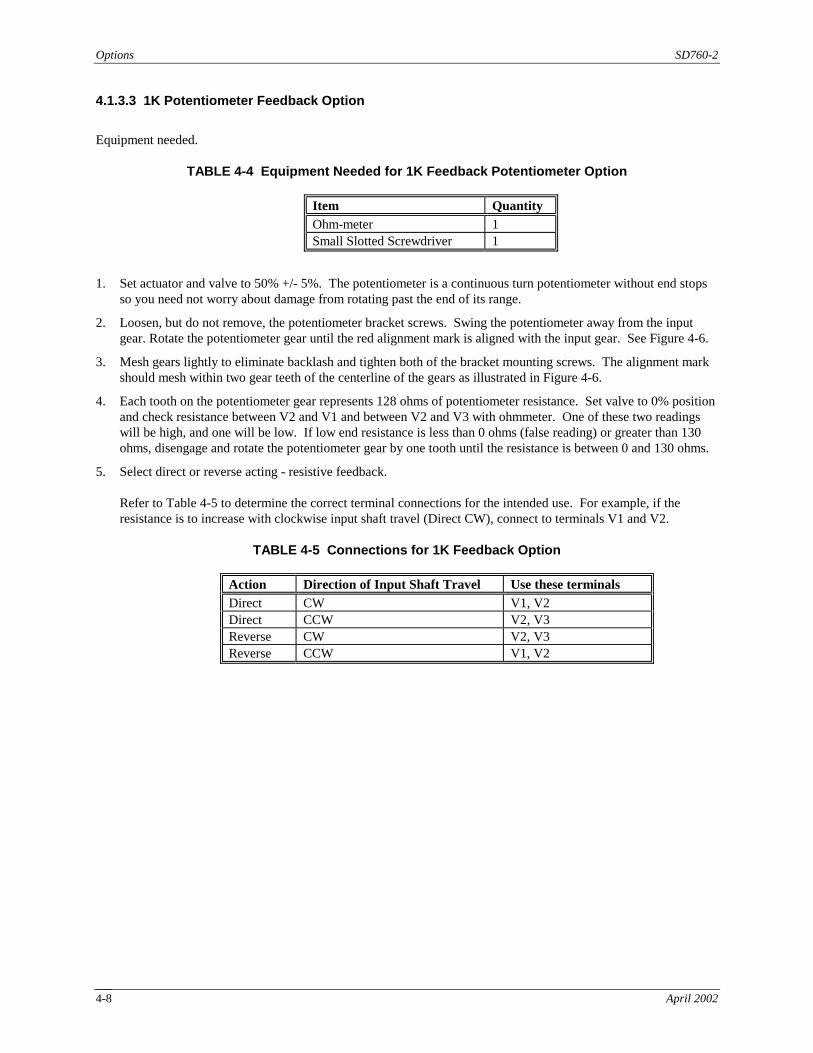
4.1.3.3 1K Potentiometer Feedback Option
Equipment needed.
TABLE 4-4 Equipment Needed for 1K Feedback Potentiometer Option
Item Quantity Ohm-meter 1 Small Slotted Screwdriver 1
1. Set actuator and valve to 50% +/- 5%. The potentiometer is a continuous turn potentiometer without end stops so you need not worry about damage from rotating past the end of its range.
2. Loosen, but do not remove, the potentiometer bracket screws. Swing the potentiometer away from the input gear. Rotate the potentiometer gear until the red alignment mark is aligned with the input gear. See Figure 4-6.
3. Mesh gears lightly to eliminate backlash and tighten both of the bracket mounting screws. The alignment mark should mesh within two gear teeth of the centerline of the gears as illustrated in Figure 4-6.
4. Each tooth on the potentiometer gear represents 128 ohms of potentiometer resistance. Set valve to 0% position and check resistance between V2 and V1 and between V2 and V3 with ohmmeter. One of these two readings will be high, and one will be low. If low end resistance is less than 0 ohms (false reading) or greater than 130 ohms, disengage and rotate the potentiometer gear by one tooth until the resistance is between 0 and 130 ohms.
5. Select direct or reverse acting - resistive feedback.
Refer to Table 4-5 to determine the correct terminal connections for the intended use. For example, if the resistance is to increase with clockwise input shaft travel (Direct CW), connect to terminals V1 and V2.
TABLE 4-5 Connections for 1K Feedback Option
Action Direction of Input Shaft Travel Use these terminals
Direct CW V1, V2 Direct CCW V2, V3 Reverse CW V2, V3 Reverse CCW V1, V2
SD760-2 Options
April 2002 4-9
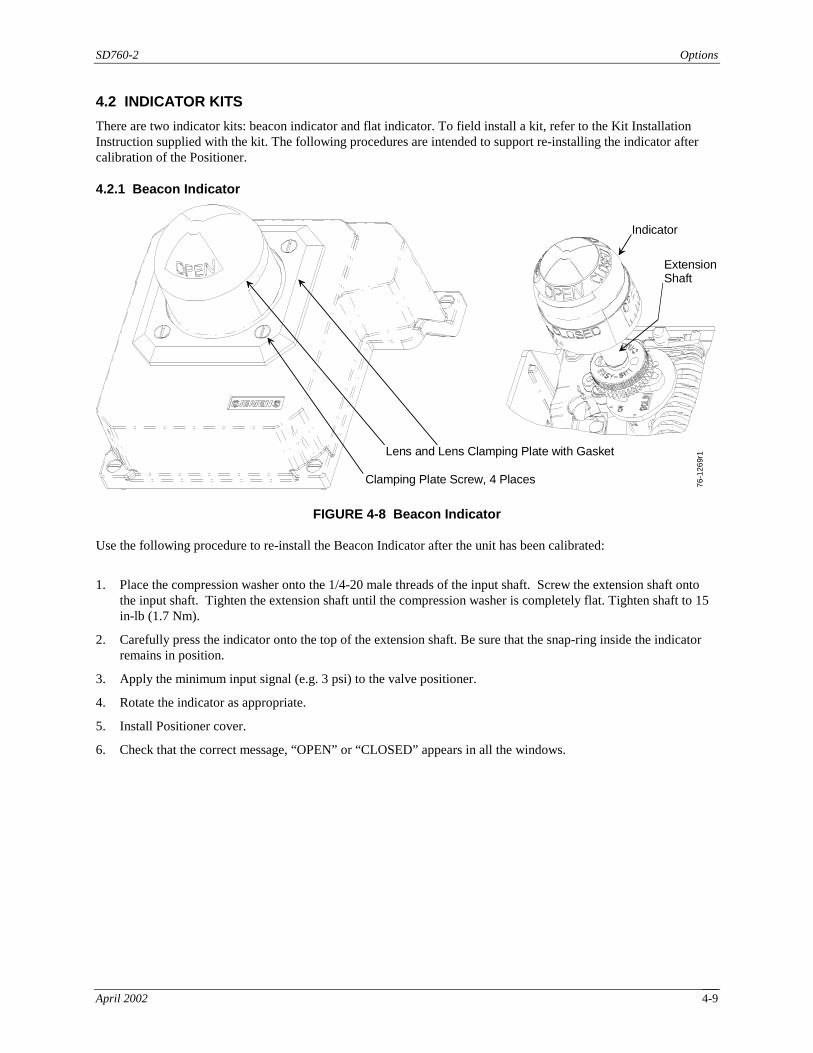
4.2 INDICATOR KITS
There are two indicator kits: beacon indicator and flat indicator. To field install a kit, refer to the Kit Installation Instruction supplied with the kit. The following procedures are intended to support re-installing the indicator after calibration of the Positioner.
4.2.1 Beacon Indicator
Lens and Lens Clamping Plate with Gasket
Indicator
ExtensionShaft
Clamping Plate Screw, 4 Places 76-1
269r
1
FIGURE 4-8 Beacon Indicator Use the following procedure to re-install the Beacon Indicator after the unit has been calibrated:
1. Place the compression washer onto the 1/4-20 male threads of the input shaft. Screw the extension shaft onto the input shaft. Tighten the extension shaft until the compression washer is completely flat. Tighten shaft to 15 in-lb (1.7 Nm).
2. Carefully press the indicator onto the top of the extension shaft. Be sure that the snap-ring inside the indicator remains in position.
3. Apply the minimum input signal (e.g. 3 psi) to the valve positioner.
4. Rotate the indicator as appropriate.
5. Install Positioner cover.
6. Check that the correct message, “OPEN” or “CLOSED” appears in all the windows.

Options SD760-2
April 2002 4-10
4.2.2 Flat Indicator
Clamping Plate Screw,4 Places
Lens andLens Clamping Platewith Gasket
Indicator
Extension Shaft
CompressionWasher
76-1
270r
1
FIGURE 4-9 Flat Indicator Use the following procedure to re-install the Flat Indicator after the unit has been calibrated:
1. Place the compression washer onto the 1/4-20 male threads of the input shaft. Screw the extension shaft onto the input shaft. Tighten the extension shaft until the compression washer is completely flat. Tighten shaft to 15 in-lbs(1.7 Nm).
2. Install the indicator onto the top of the extension shaft. Install hold down screw but do not tighten.
3. Apply the minimum input signal (e.g. 3 psi) to the valve positioner.
4. Rotate the indicator as appropriate. Tighten hold down screw.
5. Install cover.
6. Check that the indicator appears in the proper position.
4.3 FLOW OUTPUT (SPOOL) KITS
Several spool kits are available to match the output capacity and characteristic of the Positioner to an actuator. To install a kit, refer to the instruction supplied with the kit and to Section 5.3 Servicing the Spool Assembly in this manual.
SD760-2 Options
April 2002 4-11
4.4 FEEDBACK ARM AND ROTARY SHAFT KITS
This procedure is for the following kits: Feedback Arm and Rotary Shaft Kits; PN 16300- -690; 760 P/E Namur Rotary -638; 760 P/E Bray 0.5" Rotary -636; 760 P/E Bray 1.3" Rotary -693; 760 (all) 0.5 X 0.5" Square -694; 760 (all) 0.5 X 0.65" Square -695; 760 (all) 0.5 X 2" Linear -696; 760 (all) 0.5 to 4" Linear -697; 760 (all) 3 to 6" Linear -699; 760D Namur Rotary -776; 760 (all) Leslie Linear
-777; 760 (all) Bettis Rotary -778; 760 (all) Copes-Vulcan Linear -780; 760D Bray 0.55" Namur -781; 760D Bray 1.3" Namur -779; 760 (all) 3/8" Square (DeZurik Pwr Rac) -783; Rotary (90°) Cam Kit ((3) cams: LIN, QO, EP) -784; Linear (60°) Cam Kit ((3) cams: LIN, QO, EP)
Select the Cam for the Positioner Shaft
In typical applications, a rotary shaft requires a 90° cam, and a linear shaft will require a 60° cam—or for small strokes (typical ¼”) a 30° cam.
Specify cam kits as follows: 16300-783 Rotary (90°) Cam Kit ((3) cams: LIN, QO, EP) 16300-784 Linear (60°) Cam Kit ((3) cams: LIN, QO, EP) 16300-816 Linear (30°) Cam
Install the Shaft and Cam and Calibrate the Positioner Refer to Figure 6-1, an exploded view of the Positioner, and to the instruction supplied with the kit.
1. Remove cover, beacon/flat indicator, extend-o-shaft (if installed), and option board (if installed). Loosen the cam locking screw. Loosen the cam lock knob. Remove the upper and lower cam index and the cam.
2. Pull the shaft from the bottom of the enclosure. The retaining ring, thrust washer, and O-ring will stay attached. These parts are pre-installed on the shaft kits.
CAUTION
The O-Ring is Silicone, and is pre-lubricated. Do not use a Silicone based lubricant. Dow Corning 3451 is recommended
3. Insert the new shaft from the actuator side of the positioner. Rotating the shaft slightly while inserting will ease installation. Reverse step 1 to re-assemble. Refer to Section 3 Calibration for cam installation.
4. Refer to Section 3 Calibration and calibrate the positioner.
Options SD760-2
April 2002 4-12
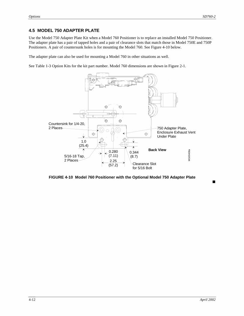
4.5 MODEL 750 ADAPTER PLATE
Use the Model 750 Adapter Plate Kit when a Model 760 Positioner is to replace an installed Model 750 Positioner. The adapter plate has a pair of tapped holes and a pair of clearance slots that match those in Model 750E and 750P Positioners. A pair of countersunk holes is for mounting the Model 760. See Figure 4-10 below. The adapter plate can also be used for mounting a Model 760 in other situations as well. See Table 1-3 Option Kits for the kit part number. Model 760 dimensions are shown in Figure 2-1.
Back View
5/16-18 Tap,2 Places
0.280(7.11)
2.25(57.2)
Countersink for 1/4-20,2 Places
1.0(25.4)
MG
0040
8a0.344(8.7)
750 Adapter Plate,Enclosure Exhaust VentUnder Plate
Clearance Slotfor 5/16 Bolt
FIGURE 4-10 Model 760 Positioner with the Optional Model 750 Adapter Plate
!

SD760-2 Maintenance
April 2002 5-1
5.0 MAINTENANCE The Positioner requires no routine maintenance. It is highly recommended that quality instrument air be used as described in Section 2.2.2 Instrument Air Requirements. The filter screens may require periodic cleaning. The frequency of their cleaning is conditional depending on the quality of instrument air used. It is also recommended that the end user perform periodic functionality tests in accordance with the critical nature of the application.
5.1 REPLACING FILTER SCREENS
Filter screens are located in the V1, V2, and supply ports. Refer to the Parts List at the back of this Instruction for the filter screen part number.
1. Turn air supply off. Disconnect piping.
2. Remove a screen with a scribe by carefully pulling on and around the edge of a screen.
3. Using a piece of stiff, hollow tubing approximately 1/4" in diameter, insert each new screen until it bottoms. Do not insert the screen using the eraser end of a pencil or a length of solid rod as it can distort the factory-shaped screen, possibly reducing maximum flow.
4. Connect piping and check for leaks.
5.2 REPLACING AN OPTION
To replace an option, refer to Section 4.0 Output Options and to the Kit Installation Instruction supplied with the kit.
5.3 SERVICING THE SPOOL VALVE ASSEMBLY
The area in which the spool valve assembly is serviced must be clean. Hands and tools must also be clean. After cleaning the assembly, reassemble it as soon as possible to prevent contamination by dust, dirt, fumes, and other environmental contaminants. Refer to Figures 5-1 and 6-1 for location of parts. When cleaning and servicing, a replacement seal and spool clip can be found in the Spare Parts Kit. Order PN16300-1249. This procedure is also used to install a Flow Output (Spool) Kit, which changes the Positioner output characteristics to accommodate the actuator. Each Kit contains a valve block and mounting screws, spool, spool clip, and seal. Figure 5-1 shows the installed valve block, spool, and spool clip. Equipment Needed:
1. A 7/64" Allen wrench (for the valve block mounting screws) and other common hand tools as determined by the installation.
2. A mild detergent or degreasing agent that will rinse clean (i.e. will not leave a residue).
3. A soft, small diameter bottle or laboratory test tube brush can be used to clean the valve block. Never use an abrasive cleaner or implements that can scratch.

Maintenance SD760-2
April 2002 5-2
Valve BlockMounting Screws
76-1
265r
3
ValveBlock
Spool,End WithRecess
Spool Clip
TholianBeam
Valve Block and Spool Clip, Top View
Spool Clip
ValveBlock
Valve Block and Spool Clip, Bottom View
Valve Block;Spool andSeal Inside
SpoolClip
Tholian Beam
Valve BlockMounting Screws,4 Places
FIGURE 5-1 Servicing the Spool Valve Assembly

SD760-2 Maintenance
April 2002 5-3
Procedure: Disassembly:
1. Remove the Positioner from service. Turn the supply air off. Remove electrical power.
WARNING
Electrical shock hazard Explosion hazard
Can cause death or injury
• Remove power from all wires and terminals before working on equipment.
• In potentially hazardous atmosphere, remove power from equipment before connecting or disconnecting power, signal, or other circuit.
• Observe all pertinent regulations regarding installation in hazardous area.
2. Disconnect pneumatic piping and electrical conduit.
3. Disconnect the actuator coupling, as needed.
4. Remove the hardware securing the Positioner to its mounting bracket. Move the Positioner to a clean location.
5. Loosen the four captive screws securing the enclosure cover. Lift the cover from the Positioner.
6. Important - Carefully note how the spool clip, shown at right, is installed. See Figure 5-1.
• Each end of the clip enters a gold-plated recess at the top and bottom of the spool valve assembly.
• The end of the clip with the three 90° bends enters the gold-plated recess in the end of the spool at the top of the valve block, across from the V2 connection.
• The end of the clip with two 90° bends enters the bronze recess at the underside of the Tholian beam, across from the V1 connection.
• The clip must fit in the U-shaped cutout in the Tholian beam, across from the V1 connection.
7. Remove the spool clip by lifting the top end of the clip only enough to clear the recess. Move the free end of the clip to one side and then free the other end of the clip. Remove the clip. Do not bend or crimp the spool clip. Replace the spool clip if it is damaged.
8. In the pneumatic connection area of the chassis casting, remove four 6-32 x 0.375 socket head screws securing the valve block.
9. Carefully pull the valve block from the housing. Do not damage or mislay the valve block seal.
10. Carefully remove the spool from the valve block. Do not scratch spool plating.
11. To service the case vent, using a pointed tool carefully work the case vent clip out of the block and remove the case vent disc. See the adjacent figure.
Valve Block Case Vent DiscCase Vent Clip
MG
76-1
271a

Maintenance SD760-2
April 2002 5-4
Cleaning:
1. Clean the spool and valve block. Be careful not to scratch spool plating.
2. Inspect the spool-block seal. Replace the seal if it is at all damaged. Assembly:
1. If the case vent is being serviced, insert a new case vent disc in the recess in the valve block and carefully press the case vent clip into the valve block.
2. Place the molded seal in the channel in the valve block.
• If installing a Flow Output Kit, get the valve block, spool, spool clip, seal, and valve block mounting screws from the Kit. A kit installation instruction is also supplied.
• If cleaning and servicing the spool assembly, use the parts removed above supplemented by parts from the Spare Parts Kit, as needed.
3. Inspect the spool. Note that one end of the spool has a recess; the other end is flat. Insert the flat end of the spool into the top of the valve block; see Figure 5-1. When the block is installed in the chassis, the spool end with the recess should be across from the V2 connection. The flat end of the spool will be across from the V1 connection and contact the Tholian beam.
4. Mount the valve block in the chassis casting using four 6-32 x 0.375 socket head screws. Tighten the valve block mounting screws to 20 in lbs (2.3 Nm) using a 7/64" Allen wrench.
5. Refer to Figure 5-1 and insert the spool clip into the bronze recess at the underside of the Tholian beam with the clip resting in the U-shaped cutout in the Tholian beam. It may be helpful to carefully lift the Tholian beam assembly slightly. Insert the free end of the clip into the recess in the spool end, at the top of the block.
6. Refer to Section 3.3 Calibration Steps and test the Positioner to ensure that the spool valve is operating freely and that there are no air leaks. Check Positioner calibration and calibrate if necessary.
7. Install the enclosure cover, tighten screws to 20 in lbs (2.3 Nm) and install the Positioner.
5.4 SPARE AND REPLACEMENT PARTS
Refer to the parts list at the back of this Instruction for a list of replacement parts and an exploded view. Spare and replacement parts are available from any of the addresses in the warranty statement. Refer to the parts list for recommended on-hand spare parts.

SD760-2 Maintenance
April 2002 5-5
5.5 RETURN FOR REPAIR
To Return for Repair Refer to Section 1.4 Product Support to contact Siemens worldwide service and support organization. Visit the
Siemens Energy & Automation web site for the latest information: http://www.sea.siemens.com/ia/. When calling, provide the reason for the return. If returning equipment for repair, failure information (e.g., error
code, failure symptom, installation environment) will be requested. A purchase order number will also be needed.
Material Safety Data Sheet A Material Safety Data Sheet (MSDS) must be included with each item being returned that was stored or used
where hazardous materials were present. Packaging Package assembly in original shipping materials. Otherwise, package it for safe shipment or contact the factory
for shipping recommendations. The 4-20mA Feedback Option Board must be placed inside a static shielding bag to protect it from electrostatic
discharge if returned separately. !

Maintenance SD760-2
April 2002 5-6

SD760-2 PARTS LIST
April 2002 6-1
6.0 PARTS LIST Refer to Section 1.3 Kits for a list of available kits. Order a kit to add or change the options in a Positioner, for example, to replace the standard 3-15 psi input with a 3-27 psi input. Order a kit to service a Positioner, for example, to replace a failed 1K ohm feedback potentiometer assembly. Spare Parts Kit 16300-1249 contains the items shown in Table 6-1. These items are used when servicing a Positioner and when performing preventive maintenance on a Positioner. An instruction is provided with the kit. This kit is a Recommended On-Hand Spare Part. An exploded view of the Positioner is on a following page. The items in the Kit are identified on the drawing.
TABLE 6-1 Service Parts Kit PN16300-1249, Contents
Item Description Quantity
1 Molded Seal, Valve Block 2
2 Spool Clip 1
3 Enclosure Cover Gasket 1
4 Diaphragm, Booster 1, Neoprene/Nylon (for Standard Temp. Units) 1, Viton® on Nomex® (for High Temp. Units)
5 Indicator Lens Gasket 1
6 Filter Screen 3
7 O-ring, 0.364 Diameter x 0.07, Block O-ring 8, Silicon
8 Disc, 0.426 ID x 0.07 W, Enclosure Exhaust Flapper 2, Silicon
9 O-ring, 1.487 ID x 0.103 W, Booster 2, Neoprene (for Standard Temp. Units) 2, Silicon (for High Temp. Units)
10 O-ring, 0.421 ID x 0.139 W, Output Shaft O-ring 1, Neoprene (for Standard Temp Units) 1, Silicon (for High Temp. Units)
11 Grease, DC 3451, Lubricate Silicon Output Shaft O-ring
1
12 Grease, DC55M, 5.3 oz. Tube, Lubricate Neoprene Output Shaft O-ring
1
13 Kit Installation Instruction 1
14 Case Vent Clip (See the detail in Section 5) 1
15 Case Vent Disc See the detail in Section 5) 1
Table 6-2 lists kits that contain replacement assemblies for servicing the Positioner.
TABLE 6-2 Assembly Replacement Kits
Description Part Number
Cam Follower Assembly 3-15 psi 3-27 psi
16300-225 16300-769
Sled Assembly 16300-344 Span Lever Assembly 16300-368 Tholian Beam Assembly 16300-1065

Parts List SD760-2
April 2002 6-2
Boo
ster
Spo
ol C
lip (
2) a
nd S
pool
Ran
ge S
prin
g
Tho
lian
Bea
m
Blo
ck
NE
MA
4X
Ven
t
Enc
losu
reG
roun
dS
crew
,2
plac
es
Nam
epla
te
Filt
er S
cree
n, 3
pla
ces
(6)
Spo
ol B
lock
Scr
ew, 4
pla
ces
Spo
ol B
lock
and
Sea
l (1)
Not
es:
1. (
#) in
dica
tes
item
is
incl
uded
in S
ervi
ce P
arts
K
it P
/N 1
6300
-124
9.2.
Som
e op
tiona
l as
sem
blie
s ar
e sh
own.
Dia
phra
gm (
4)
O-R
ing
(9)
Enc
losu
reC
over
Gas
ket (
3)
Indi
cato
rLe
nsG
aske
t (5)
Bea
con
Indi
cato
r
Fla
t Ind
icat
orC
am
Cam
Loc
k
Opt
ion
Boa
rdan
dS
tand
offs
Enc
losu
reE
xhau
st
O-R
ing
(10)
, App
lyG
reas
e (1
1) o
r (1
2)
O-R
ing,
2 pl
aces
(7)
Dis
c (8
)
Ele
ctric
alE
ntra
nces
Fee
dbac
k Le
ver
and
Ret
aini
ng C
lip
Inpu
t Sha
ft
Nameplate
Enc
losu
reC
over
Oth
er S
uppl
ed C
ams
Leve
ran
d C
amF
ollo
wer
76-1
000r
3(M
G00
406a
)
A
A
FIGURE 6-1 Model 760P (Design Level C), Exploded View !

SD760-2 FAQs
April 2002 7-1
7.0 FAQs The following are some common questions asked about the Positioner and the answers to those questions.
Question Answer
Can the Positioner provide double acting service?
Yes. The Positioner supports single and double acting services. There are two output ports. One port is plugged in single acting service; both ports are used in double acting service. See Section 2.4 Pneumatic Connections.
Can the Positioner be used in reverse acting applications?
Yes. There are two output ports: V1 and V2. V1 is reverse acting (i.e. pressure decreases with increasing input signal). V2 is direct acting (i.e. pressure increases with increasing input signal). See Section 2.4 Pneumatic Connections.
Can the feedback method be changed in the field?
Yes. A variety of rectilinear levers and rotary shafts are available and are field installable. See Shaft and Lever Kits in Table 1-3 Option Kits. Contact the factory for specialized needs.
The 4-20 mA Feedback Option Board will not supply 20 mA. What is wrong?
Refer to Section 3 Calibration and attempt to calibrate the Positioner. If calibration is unsuccessful, check the alignment of the potentiometer as described in Section 4.1 PC Board-Base Options. The feedback potentiometer must rotate the full amount: 60° for rising stem applications, 90° for rotary applications.
How can I determine which direction the cam is rotating?
Apply an increasing input signal and observe the direction of rotation of the cam. Use the cam lobe on which the cam follower is riding when indexing the cam. See Figure 3-1.
Why is the Positioner output irregular?
Refer to Section 5.3 Servicing the Spool Assembly. Check that the spool clip is properly installed, as shown in Figure 5-1. Check that spool movement is smooth; clean the valve block and spool. Check for air leaks. Check the feedback mechanism for smooth, consistent operation. Refer to Section 2.2 Mechanical Installation and Section 2.3 Retaining Clip Installation.
How are the proximity sensors employed?
The proximity sensors are not intended to carry a load current. Instead, wire the sensors to a switch transfer barrier, as described in Section 4.1.2.1 Mechanical Limit Switches and Proximity Sensors.

FAQs SD760-2
April 2002 7-2

SD760-2 Warranty
April 2002 8-1
8.0 WARRANTY The Company warrants all equipment manufactured by it and bearing its nameplate, and all repairs made by it, to be free from defects in material and workmanship under normal use and service. If any part of the equipment herein described, and sold by the Company, proves to be defective in material or workmanship and if such part is within twelve months from date of shipment from the Company's factory, returned to such factory, transportation charges prepaid, and if the same is found by the Company to be defective in material or workmanship, it will be replaced or repaired, free of charge, f.o.b. company's factory. The Company assumes no liability for the consequence of its use or misuse by Purchaser, his employees or others. A defect in the meaning of this warranty in any part of said equipment shall not, when such part is capable of being renewed, repaired or replaced, operate to condemn such equipment. This warranty is expressly in lieu of all other warranties, guaranties, obligations, or liabilities, expressed or implied by the Company or its representatives. All statutory or implied warranties other than title, are hereby expressly negated and excluded. Warranty repair or replacement requires the equipment to be returned to one of the following address. Siemens Energy & Automation, Inc. Process Industries Division, Process Instrumentation 1201 Sumneytown Pike P.O. Box 900 Spring House, PA 19477-0900 The warranty will be null and void if repair is attempted without authorization by a member of the Siemens Technical Support Group (North America) or Technical Information Center (Asia and Europe).
!

Warranty SD760-2
April 2002 8-2
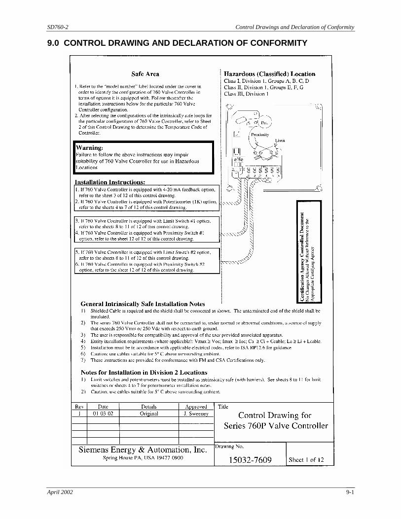
SD760-2 Control Drawings and Declaration of Conformity
April 2002 9-1
9.0 CONTROL DRAWING AND DECLARATION OF CONFORMITY

Control Drawings and Declaration of Conformity SD760-2
April 2002 9-2

SD760-2 Control Drawings and Declaration of Conformity
April 2002 9-3

Control Drawings and Declaration of Conformity SD760-2
April 2002 9-4

SD760-2 Control Drawings and Declaration of Conformity
April 2002 9-5

Control Drawings and Declaration of Conformity SD760-2
April 2002 9-6

SD760-2 Control Drawings and Declaration of Conformity
April 2002 9-7
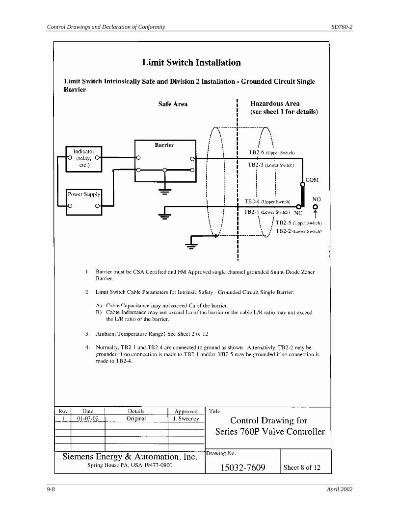
Control Drawings and Declaration of Conformity SD760-2
April 2002 9-8

SD760-2 Control Drawings and Declaration of Conformity
April 2002 9-9

Control Drawings and Declaration of Conformity SD760-2
April 2002 9-10

SD760-2 Control Drawings and Declaration of Conformity
April 2002 9-11

Control Drawings and Declaration of Conformity SD760-2
April 2002 9-12

SD760-2 Control Drawings and Declaration of Conformity
April 2002 9-13
!