value added metal extraction from red mud
TRANSCRIPT
VALUE ADDED METAL EXTRACTION FROM RED MUD
Thesis submitted in partial fulfilment of the requirements for the award of the degree of
Master of Technology
In
Mechanical Engineering
[Specialization: Steel Technology]
Submitted by
Ankur Pyasi
Roll No. - 212MM2422
Department of Metallurgical and Materials Engineering
National Institute of Technology
Rourkela-769008
May 2014

National Institute of Technology Rourkela
Certificate
This is to certify that the thesis entitled “Value added metal extraction from red mud”
submitted by Ankur pyasi in partial fulfilment of the requirement for the degree of “Master
of Technology” in Mechanical Engineering with specialization in Steel technology, is a
bonafide work carried out by him under our supervision and guidance. In our opinion, the
work fulfils the requirement for which it is being submitted.
Supervisor
Prof. Smarajit sarkar
Department of Metallurgical & Materials Engineering
National Institute of Technology, Rourkela
Rourkela – 769008
Email: [email protected]

Acknowledgment
I wish to express my sincere gratitude to my supervisor Prof. Smarajit sarkar, for giving me
an opportunity to work on this project, for his guidance, encouragement and support
throughout this work and my studies here at NIT Rourkela. His impressive knowledge,
technical skills and human qualities have been a source of inspiration and a model for me to
follow.
I like to express my deep sense of respect and gratitude to Dr. B.Mishra, Dy. Director at
DISIR Rajgangpur, Odisha for their useful suggestions and help rendered to me in carrying
out this work.
I am grateful to Prof. B C Roy, present Head of the Department of Metallurgical & Materials
Engineering Department for providing facilities for smooth conduct of this work. I am
especially grateful to Metallurgical Laboratory supporting staffs without them the work
would have not progressed.
I am also thankful to Mr. Shubhashis kar and my colleague for extending their technical and
personal support and making my stay pleasant and enjoyable.
ANKUR PYASI
Roll No: 212MM2422
(Steel technology)
NIT Rourkela
CONTENTS
ABSTRACT……………………………………………………………………………………i
LIST OF FIGURES…………………………………………………………………………...ii
LIST OF TABLES……………………………………………………………………………iii
CHAPTER: 1
INTRODUCTION……………………………………………………………………………1
1.1Background………………………………………………………………………………...2
1.2 Inspiration for project……………………………………………………………………...2
CHAPTER: 2
LITERATURE REVIEW……………………………………………………………………4
2.1 Natural history of bauxite………………………………………………………………….5
2.1.1 Ore precipitation and mineral processing……………………………………………….6
2.1.2 Bayer processing over view……………………………………………………………..6
2.1.3 Digestion of bauxite……………………………………………………………………..7
2.2 Nature of red mud………………………………………………………………………..12
2.3 Background of red mud…………………………………………………………………..14
2.3.1 Previous red mud solution efforts……………………………………………………...14
2.3.2 Current methods of treatments, storage and associated problems…………………….17
2.3.2.1 Closed cycle disposal………………………………………………………………...18
2.3.2.2 Dry stacking method or thickened tailing disposal………………………………….19
2.3.2.3 Sea disposal…………………………………………………………………………..20
2.3.3 Sources of red mud……………………………………………………………………..21
2.3.4 Properties of red mud…………………………………………………………………..21

2.3.5 Application of red………………………………………………………………………22
CHAPTER: 3
MATERIAL AND METHODS…………………………………………………………….23
3.1 Materials………………………………………………………………………………….24
3.1.1Red mud………………………………………………………………………………...24
3.1.2 Aluminum powder……………………………………………………………………..25
3.1.3 Coke……………………………………………………………………………………25
3.1.4 Lime……………………………………………………………………………………26
3.2 Homogenization………………………………………………………………………….26
3.3 work plan…………………………………………………………………………………27
3.4 Material preparation……………………………………………………………………...27
3.5 Plasma Reactor …………………………………………………………………………..29
3.5.1 Smelting process……………………………………………………………………….30
3.6 Material characterization…………………………………………………………………31
3.6.1 Phase analysis by XRD………………………………………………………………...31
3.6.1.1 Sample preparation…………………………………………………………………..31
3.6.2 Micro structural analysis by optical microscope………………………………………33
3.6.2.1 Sample preparation…………………………………………………………………...33
CHAPTER: 4
RESULT AND DISCUSSION……………………………………………………………...34
4.1 Sample A (15% coke + 85% red mud)…………………………………………………...35
4.1.1 XRD analysis…………………………………………………………………………...35
4.2Sample B (75%redmud+10%coke+10%lime+5%aluminium powder)………………….37

4.2.1 XRD analysis…………………………………………………………………………...37
4.3 Sample C (65%redmud+15%coke+15%lime+5%aluminium powder)………………….39
4.3.1XRD analysis……………………………………………………………………………39
4.4 Microscopic result………………………………………………………………………..41
4.1.1 Sample A……………………………………………………………………………….41
4.4.2 Sample B……………………………………………………………………………….42
4.4.3 Sample C……………………………………………………………………………….43
4.5 Discussion………………………………………………………………………………..44
CHAPTER- 5
CONCLUSION......................................................................................................................45
5.1. Conclusion……………………………………………………………………………….46
5.2. Scope for future future work…………………………………………………………….46
REFERENCES…………………………………………………………………………..47-50

i
ABSTRACT
In the presented thesis work, utilization of red mud for extraction of value added product is
discussed. Huge quantity of red mud is being generated by aluminium industry which is a
potentially hazardous material and creating environmental pollution. Red mud samples
collected from Nalco Indicates apart from Iron oxide the other phase of interest is titanium
oxide. In the present work Ferro titanium extraction is tried by carbothermic reduction in
export arc plasma furnace utilizing both nitrogen and Argon as the ionizing gases. Also for
efficient extraction of metallic phases lime has been added to generate slagging phases which
melts at comparatively lower temperature. Also in the present work, Aluminium dross has
been added to the charge material to facilitate the metal extraction at a comparatively lower
temperature .After fusion the fused material is crushed to separate the metal and gaunge
phase which has been characterised by XRD and microscopy. The analysis indicates good
degree of metallization in form of Ferro-titanium.

ii
LIST OF FIGURES
Fig. 2.1: A schematic representation of the Bayer process
Fig. 2.2: Worldwide red mud generation
Fig. 3.1: Red mud
Fig. 3.2: Aluminium powder
Fig. 3.3: Coke
Fig. 3.4: Lime
Fig. 3.5: Pulveriser
Fig. 3.6: Work plan for experiment
Fig. 3.7: Schematic diagram of plasma arc reactor
Fig. 3.8: Smelting process in plasma furnace
Fig. 3.9: Smelting process
Fig. 3.10: XRD machine
Fig. 3.11: Optical microscope
Fig. 4.1: XRD pattern of sample A
Fig. 4.2: XRD pattern of sample A
Fig. 4.3: XRD pattern of sample B
Fig. 4.4 XRD pattern of sample B for non magnetic material
Fig. 4.5: XRD pattern of sample C for magnetic material
Fig. 4.6: XRD pattern of sample C for non magnetic materials
Fig. 4.7: Microstructure of sample A for metal part
Fig.4.8: Microstructure of sample A for non metallic part

iii
Fig. 4.9: Microstructure of sample B for metallic part
Fig. 4.10: Microstructure of sample B for non metallic part
Fig. 4.11: Microstructure of sample C for metallic part
Fig. 4.12: Microstructure of sample C for non-metal part
LIST OF TABLES
Table 1.1: Composition of bauxite and the generated red mud
Table 2.1: Geotechnical properties of red mud
Table 2.2: Phases present in red mud
Table 2.3: Incidents in the past 10 years
Table 2.4: Plant capacity and dumping procedure
Table 2.5: Wt% of element in red mud
Table 3.1: Chemical analysis of red mud
Table 3.2: Composition of sample A
Table 3.3: Composition of sample B
Table 3.4: Composition of sample C
Table 3.5: Parameters of XRD
Table 4.1: Operating condition during processing
Table 4.2: Result of sample A after processing
Table 4.3 XRD analysis of sample A
Table 4.4: XRD analysis of sample A
Table 4.5: Result of sample B after processing
Table 4.6: XRD analysis of sample B

iv
Table 4.7: XRD analysis of sample B
Table 4.8: Result of sample C after processing
Table 4.9: XRD analysis of sample C for magnetic materials
Table 4.10: XRD analysis of sample C for non magnetic materials

1
CHAPTER 1
INTRODUCTION

2
1.1. Background:
Red mud is the solid waste material which is produced during the production of alumina
(Al2O3) in the bauxite industry. Red mud is generated by Bayer’s process. Quality and
processing of ores containing aluminium defines the amount of red mud produced. 1 to 15
tonnes of dry red mud is generated during production of 1tones of alumina. There is no other
economic method which generates red mud during production of aluminium from bauxite. In
India 1.892 million tons per year aluminium is produced by aluminium industry. Metal
production of 6×10⁵tonnes/ year generates nearly 2×10⁶ tonnes of red mud every year.
Globally 9×10⁷tonnes of red mud is produced. The red mud has high alkalinity (pH 11-12.5).
It contains Fe2O3, Al2O3, SiO2, Na2O and CaO. Zr, Y, Th, U elements also present in trace
amount. It has reddish-brown colour. [1, 2, 10, 12, 15]
1.2. Inspirations for project:
The expenses involved in the transportation and pollution abatement are serious problems
faced by industry of aluminium in dumping of Red mud. A 30%-50% Fe2O3 and remaining
Al2O3 and SiO2 is the typical composition for red mud. Trace amount of metallic elements
such as Vanadium, chromium, magnesium and Zirconium are also present in red. Haematite,
goethite, Anatase, Rutile, Quartz and sodalite are their major components. So, red mud is a
potential source of many metals.
Red mud is used in the cement industry for the manufacture of tiles, but such applications can
utilize only small amount of red mud produced over the year. Processes for metallurgical as
well as non-metallurgical applications of red mud have been developed. Up till now, red mud
has found limited commercial utilization in road making Portland cement. Suitable
metallurgical processes for metal recovery from red Mud is important for bulk utilization.
Value addition and moving towards zero waste. To recover iron values from red mud two
main approaches which have been generally investigated are based on:
1. Iron recovery by solid state reduction of red mud followed by magnetic separation.
2. Pig iron production through smelting in a blast /electric/low shaft furnace.
There are several processes which exist to recover metals from red mud, but unfortunately
none of these are practiced in commercial operation. By using hardening process, new
construction material from red mud has been developed. Thermal plasma technology is now

3
an established alternative which is capable enough for improving the existing metallurgical
processes. In the thermal plasma process, uniform heat transfer to the charge material occurs
due to high density of ionic charges. The reactions are completed in very short duration due
to availability of very high temperature, high energy fluxes, and plasma state conditions in
the plasma arc. They have the advantage of allowing the direct use of Fine feed materials.
[10, 12]
India is rich in mineral resources and has a long history of mining, is a well known body in
mineral producing countries of the world. The Indian economy to a great extent depends on
the value of the mineral produced. They represent a major portion of raw materials for
country’s industrial activities. The lack of finance solutions to the problem of red mud allows
room for major progression with the current price of metals at record highs. For most
important metals, the climate for advancements has never been better. As shown in table
below, composition of generated red mud compound and bauxite. Red mud is a concentration
of many elements, aluminium mainly. Composition of bauxite and the generated red mud
compound as shown in table.
Table 1.1: Composition of bauxite and the generated red mud
SL.No. Element Bauxite (%) Red mud (%)
1 Al2O3 56.4 14.7
2 SiO2 0.7 2.6
3 CaO 1.2 8.8
4 TiO2 4.3 7.2
5 Fe2O3 35.1 60.7
6 Na2O 0 1.6
7
Other
(P,S,Cr,Mn,Hg,Pb,Zn,Cd) 2.3

4
CHAPTER 2
LITERATURE REVIEW

5
2.1. Natural history of Bauxite:
Bauxite is an abbreviation applied to a naturally occurring mixture of minerals which are rich
in hydrated aluminium oxides. Oxides of iron, silicon, and titanium are major impurities
while such elements as zinc, phosphorous, nickel and vanadium are found in trace amount.
The type of process needed for alumina production is defined by mineralogical characteristics
of the bauxite ore. For the case of aluminium containing minerals, it is important to note
whether gibbsite, Boehmite, diasporic mineralogy is dominant. This determines the type of
leaching operation to be used. The world’s metallurgical bauxite production, as per this
mineralogy is listed in presence of silica, usually called active. Since, the active silica
determines the process required in the same. Because, the production of aluminium is also
continuously rising, it can be concluded that production of bauxite is continuously on a high.
Bauxite ore refers to a deposit of the material that contains high levels of aluminium oxide
( ) and low levels of hematite (FeO3) and silica (SiO2). Bauxite’s composition is such
that it makes the ore economically mineable in a variety of locations across the globe. Other
rich sources of aluminium include a variety of rocks and minerals which includes aluminous
shale and slate, aluminium phosphate rock and Kaolites (high alumina clays), etc. [27].
Bauxite deposits are frequently extremely extensive this is due to their method of formation
over the geological timeline, and therefore, they are found on almost all continents of the
world as shown in Figure 2-3: Locations of Bauxite Mining.
Although, bauxite is found worldwide. The countries with the largest economically mineable
deposits, in order of production are Jamaica, Australia, Brazil, Guinea, and India. The largest
consumers of aluminium of year 2002 are The United States of America, Japan and Germany.
All the three countries do not possess any or very little, bauxite deposits [27].
The only ore currently being used for the production of aluminium is bauxite. Bauxite
consists of many hydrous aluminium oxide phases in combination with iron, silicon, titanium
oxides and other trace impurities. Main mineral present in bauxite, Gibbsite (Al (OH) 3),
boehmite (-AlO (OH)), and diaspore (-AlO (OH)) a form of boehmite that exhibits a more
dense state. Actual hardness of the ore depends on location on the globe where it is found. As
friable compacted earth, re- cemented compacted earth, pisolites (small balls), tublules (twig
like hollow material) have been reported across the globe. [10].
6
2.1.1. Ore preparation and Mineral processing:
Since, each ore requires a unique processing therefore, a lack of published literature in the
area of mineral processing and ore preparation is present. To facilitate efficient digestion, at
this stage, a function of providing a continuous, consistent and appropriately charged feed to
the digesters in the Bayer process is done [10]. Generally, the material is washed first and
screened, to remove irrelevant contaminant such as dirt [29]. This procedure is usually
completed at the mine. Particle size is regulated/ fixed in the same location where the rest of
the Bayer process takes place. A great number of plants now utilize wet grinding mills. Wet
grinding mills are charged with the bauxite ore and a portion of the process solution in order
to make slurry. In Western Australia Completely autogenously mills with diameters over 25
feet are utilizing approximately 8 inch hard bauxite agglomerates as grinding media [10]. To
return the oversize particles to the mill for further grinding Hydro cyclones and screens are
used. To utilize abrasion and finalize particle size reduction Research has been done on the
effects of holding the ground slurry for extended time periods in mechanically agitated tanks
[28].
2.1.2. Bayer processing over view:
Bayer process is an economical solution for producing aluminium oxides from bauxite ore
using concentrated NaOH solution (caustic soda) at high pressure and temperature. The
Bayer process was invented in 1887 by the Austrian chemist Karl Bayer. Russia, to develop a
method for supplying alumina to textile industry as alumina was used as a mordant in dyeing
cotton. In 1887, Bayer discovered that the aluminium hydroxide, precipitated from alkaline
solution was crystalline and could easily filter and washed. The NaOH selectively dissolves
Al2O3 from bauxite ore; this produces sodium –aluminium solution from which pure alumina
Tri- hydrates. Then, Al (OH)3 precipitation is done, which is than calcined to produce Al2O3 ,
from which metal is recovered.[36]
A few years earlier, hennery Louis le chatelier in France develop a method for making
alumina by heating bauxite in sodium carbonate, Na2Co3 at 1200 C, leaching the sodium
aluminate formed with water. Then, precipitation of Al (OH)3 by Co2 was done, which was
then filtered and dried. This process was abandoned in favour of the Bayer process. Since, the
Bayer process is capable of producing huge quantities aluminium oxide and aluminium
hydroxide with high – purity aluminium at relatively low – cost. This in fact created
opportunity for marketing profitable Bayer plant products outside the aluminium industry. A

7
breakthrough in the quest for a cost-effective production process for aluminium occurred in
1886. With invention of the electrolytic aluminium process invented in 1886, the process
began to get importance in metallurgy. The cyanidation process was also invented in 1887.
The Bayer process is the birth of the modern field of hydrometallurgy. Today the process is
virtually unchanged and it produces nearly all the world’s alumina supply.
The Bayer process is the principal industrial method of refining bauxite to produce alumina.
Bauxite is the most important ore of aluminium. It contains only 30-54% alumina, Al2O3. The
rest is a mixture of silica, various iron oxides, and titanium dioxide, phosphorous and also
zinc, nickel and vanadium, etc. are found in trace amount. The alumina must be purified
before it can be refined to aluminium. [36]
A Bayer process plant is basically, a device for heating and cooling a large recirculating
stream of caustic soda solution. Bauxite is added at the high temperature point; red mud is
separated at an intermediate temperature. Then, alumina is precipitated at the low temperature
point.
Bauxite usually consists of two forms of alumina a monohydrate from Tri-hydrate from
gibbsite (Al2O3. 3H2O) and boehmite (Al2O3.H2O). Boehmite requires elevated
temperature (above 200c). To dissolve reading in 10% NaOH solution at temperature below
150c. Alumina is produce by Bayer’s process through the continuous four stages which can
be stated as:
2.1.3. Digestion of bauxite:
Selective dissolution of alumina from ore.
(a) Grinding: bauxite ore is finely grinded by ball mill to size < 20mm to allow better solid –
liquid contact during digestion, then recycled caustic soda solution is added to produce pump-
able slurry and lime is introduced for mud condition and phosphate control.
(b) Desilication: The silica component of the bauxite is chemically reacted with caustic soda
this causes alumina and soda losses by combining to solid desilication products. To desilicate
the slurry before digestion, it is heated. It is then projected to atmospheric pressure in the pre-
treatment tanks. Most desilication products pass out with the mud waste as sodium-
aluminium silicate compounds.

8
(c) Digestion: in digestion bauxite slurry is pumped by high pressure pumps through agitated
vertical digester vessels which operate in series. After this, it is mixed with steam and caustic
solution. This dissolves the alumina content of the bauxite selectively and then forms a
concentrated sodium alumina solution and leaves un-dissolved impurities. Reaction condition
to extract the monohydrate alumina are about 250 C and a pressure of about 3500 kPa,
achieved by steam generated at 5000 kPa in coal fired Boilers. However, for trihydrate
alumina temperature of digestion is < 150 C.
The chemical reactions can be given as:
2NaOH+Al2O3 . 3H2O = 2NaAlO2 + 4H2O
2NaOH + Al2O3 . H2O = 2NaAlO2 + 2H2O
After digestion, about 30% of the bauxite mass remains in suspension as thin red mud as
slurry of silicate and oxide of iron and titanium. By flowing through a series of flash vessels,
the mud – laden liquor leaving the digestion vessel is flash- cooled to atmospheric boiling
point which is then operated at lower pressure.[10]
(2) Clarification of the liquor stream: setting out un-dissolved impurities
(a) Settlers: most red mud waste solids are settled from the liquor stream in single deck
settling tanks. To improve the rate of mud settling and achieve good clarity in the overflow
liquor stream, flocculants are added to the settler feed.
(b) Washers: Here, the mud is washed with fresh water in counter – current washing process
to remove the soda and alumina content in the mud before being pumped to large disposal
dams, slacked Lime is also added to remove Na2CO3 , which is formed by reaction with
compounds in bauxite and also from the atmospheric Co2. C02 reduces the effectiveness of
liquor to dissolve alumina and lime regenerates caustic soda, allowing the insoluble calcium
carbonate in precipitated form, to be removed with the waste red mud. Following reaction can
be shown below:
Na2CO3 + Ca (OH)2= CaCO3 + 2 NaOH
(C) Filters: settlers overflow liquor containing traces of fine mud which is filtered in Kelly –
type constant pressure filters using polypropylene filter cloth.

9
(3) Precipitation of alumina tri-hydrate:
(a) Crystallization: dissolved alumina is recovered from the liquor by precipitation of
crystals. Alumina precipitates as the tri-hydrate (Al2O3 . 3H2O) in a reaction, which is the
reverse of the digestion of tri-hydrate:
2NaAl2 + 4H2O = Al2O3 .3H2O + 2NaOH
The cooled pregnant liquor flows to rows of precipitation tanks which are seeded with
previously Precipitated crystalline tri-hydrate alumina. Usually they are of an intermediate or
fine particle size to assist crystal growth. The correct particle size is important to smelter
operations. So, sizing is carefully controlled. The finished mix of crystal sizes is settled from
the liquor stream and separated into their size ranges “gravity” classification tanks.
Caustic liquor which is essentially free from solids overflows from the tertiary classifiers and
then it is returned through an evaporation stage where it is re-concentrated, heated and
recycled to dissolve more alumina in the digesters. Fresh caustic soda is added to the stream
to make up for process losses.
(4) Calcinations of alumina:
Slurry of Al2O3.3H2O from the primary thickeners is pumped to hydrate storage tanks and
then to remove process liquor it is washed on horizontal – table vaccume filters. The resulting
filter cake is fed to a series of calcining units and by circulating fluidized bed calciner or
rotary kilns the feed material is calcined at 1100c to remove both free moisture and
chemically combined water.
2Al (OH)3 + heat = Al2O3 + 3H2O
The circulating fluidized bed calciner is more energy efficient than the rotary kiln. Finally it
produces 90% sandy alumina particles of size +45 micron. To cool the calcined alumina from
the rotary kiln, Rotary or satellite coolers are used. Further Fluidised–bed coolers reduce
alumina temperature to less than 90c, before it is discharged into conveyer belts, which carry
it into storage buildings.[30]
Alumina (aluminium oxide, Al2O3) is a fine white material and is the main component of
bauxite. The largest manufactures in the world of alumina are ALCAN, ALCOA, RUCAL,
NALCO, Queensland Alumina Limited (QAL) etc.

10
The residue also contains alumina which is undisclosed during the alumina extraction from
bauxite. Other components of bauxite Fe2O3 ,SiO2 ,TiO2 etc do not dissolve in the basic
medium. Some SiO2 dissolve as silicate Si (OH)6-2
and are then filtered from the solution as
solid impurities (clarification) for various reasons. Most alumina producer adds lime at some
point in the process and the lime forms a number of compounds that end up with the bauxite
residue. The red mud is the solid impurities remained. The red mud, due to its caustic nature
causes disposal problem.
A large amount of the alumina produced is then subsequently smelted in the hall-heroult
process, in order to produce aluminium. Metallic aluminium is very reactive with
atmospheric oxygen, and then thin passive layer of alumina quickly forms on any exposed
aluminium surface. This layer protects the metal from further oxidation due to its passive
nature. Through anodizing thickness and properties of this oxide layer can be enhanced. A
number of alloys, such as aluminium, magnalum, bronzes are prepared to enhance corrosion
resistance. One metal whose growth in the past century has been very fast is aluminium. Its
strength and light weight guarantees its demand, especially in transportation where fuel
efficiency is of apex importance.
Annual world production of alumina is approximately 45 million tons, over 90% of which is
used in the manufacture of aluminium metal. Due to high melting point Al2O3 is a refractory
material. The major uses of aluminium oxides are in refractory, polishing, ceramics and
abrasive applications.
An aluminium oxide is an electrical insulator, but still has a relatively high thermal
conductivity. The is α-Al2O3 called corundum, most commonly occurring crystal line
alumina. Its hardness makes it suitable for use as an abrasive and also as a component in
cutting tools. Bauxite residue (also known as “red mud”) is a by-product of the Bayer process
(shown in fig. 2.1) [12]. Its colour is red, due to presence of iron oxides. The amount of
residue generated, per ton of alumina produced varies greatly. It depends on the type of
bauxite used i.e. from 0.3 tons for high grade bauxite to 2.5 tons for very low grade. The
chemical and physical properties of red mud depends primarily on the bauxite used and to a
lesser extent the manner in which it is processed. The main solid waste product of alumina
industry is Red mud. The world wide annual production of red mud is 70 million tons. Its
disposal remains an issue of great importance.

11
Fig. 2.1: A schematic representation of the Bayer process.
12
2.2. Nature of Red mud:
A red mud created from the production of alumina using the Bayer process, has proven to be
difficult to deal with because of its particular characteristics. The complexity is increased due
to the extreme diversity in each red mud product created. There are 22 phases that are
typically present in red mud as shown in Table 2.2: Composition of Dried North Coast
Jamaican Bauxite and the Generated Red Mud Compound [33] and Table 2-2 [33] shows an
overview of the general properties of red mud that make it thixotropic, difficult to settle
because of its fine particle size and extreme alkalinity [10]. The major oxides present in red
mud and their weight percents are: Fe2O3 (25-70%), Al2O3 (13-29%) , SiO2 (3-24%), TiO2
(4-20%), CaO (0.1-12%), Na2O (1-10%) with the rest of the 7-13 wt % being made up of V,
Ga, P, B, Cd, K, Sr, Ba, Zn, Mg, U, Sb, Bi, Mn, Cu, Ni, Th, Zr, Hf, As, Co, W, Ta, Hg, and
Nb. [33]
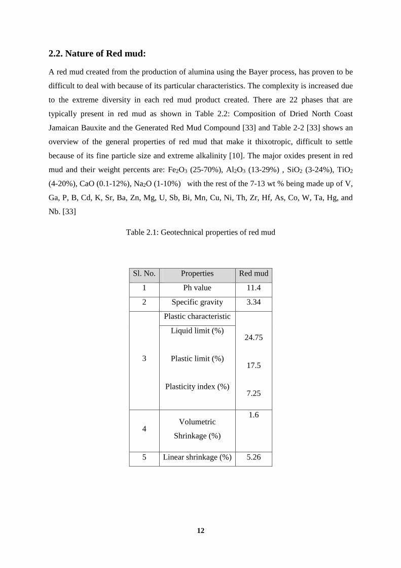
Table 2.1: Geotechnical properties of red mud
Sl. No. Properties Red mud
1 Ph value 11.4
2 Specific gravity 3.34
3
Plastic characteristic
24.75
17.5
7.25
Liquid limit (%)
Plastic limit (%)
Plasticity index (%)
4 Volumetric
Shrinkage (%)
1.6
5 Linear shrinkage (%) 5.26

13
Table 2.2: Phases present in red mud
SL. no. Phase Chemical composition
1 Gibbsite Al2O3* 3H2O , Al (OH)3
2 Boehmite AlO*OH
3 Diaspore αAlO*OH
4 Kaolinite Al2Si2O5(OH)4
5 Sodalites 3(Na2AlSiO4)6 *2H2O
6 Calcium Aluminate CaO*Al2O3
7 Sodium Alumino silicate 3Na2O*Al2O3*3SiO2*XH2O
8 Hematite αFe2O3
9 Magnetite
Goethite
γFe2O3
αFeO*OH
10 Maghamite Fe2O3
11 Siderite FeCo3
12 Calcite CaCo3
13 Calcium alumina silicates
14 Alumogeothite αFeAlO*OH
15 Anatase TiO2
16 Rutile TiO2
17 Sodium titanate Na2TiO3
18 Cancrites Na6CaCO3(AlSiO4)*2H2O
19 Quartz SiO2
20 Ca (Mg,Al,Fe) titanate
22 Magnesite MgCO3

14
2.3. Background of Red mud:
Extensive research was done approximately 20 years ago and further. At that time
researcher’s focus was on the recovery of aluminium and iron. Attempts were also made to
develop a safe material from red mud that could be used for building materials. There has
been successful implementation of this in Jamaica with a building constructed of the pseuso-
geopolymers created using red mud. It was done almost 20 years ago; this implies that the
recycling of red mud has been researched for many years. One possibility for this lack of
current research is that, in general, research has moved away from iron and aluminium
recycling to things of more values such as precious metals such gold and rare earth element
extraction such as platinum.
The reason that previous research did not provide any economic answers to the problem is
perhaps the difficulty of working with the red mud, due to extensive silicates and liberation
problems.
Because, the modern high grade deposits of the Bauxite ore are no longer in developed
countries, they are now being mined in developing countries such as Papua, China, India,
Yugoslavia, New Guinea, and Russia. These countries are not as conscious about the
environment and thus there is no push for public research to continue. Therefore, most recent
research has been completed by the aluminium companies themselves. Because of all this, the
research has been at setback and not shared with the academic community thus current
information is extremely lacking and inadequate. [9]
There have been various other papers and smaller research projects that can be found on the
redmud.org website. This research is primarily focusing on the extraction of rare earth
element as well as the development of construction material from red mud.
Although, there have been research and successful applications of construction materials, it is
unclear if this is an oversight. Research is being duplicated or if advancements are being
made. The goal of this research is to develop a process that will effectively and economically
extract the iron and alumina from red mud using plasma technique.
2.3.1. Previous Red Mud Solution Efforts:
Application of red mud has been tried in limited scenario, as a constituent in industrial
construction aggregates, road surface material, such as bricks, and cement, in combination

15
with other waste products such as fly ash. It has also been tried as a soil modifier. For waste
utilization after metal extraction, these applications do not add value but can serve as a valid
route. Construction material applications consideration is required for addressing the vastness
of the problem [14].
One investigator suggests separation of the red mud (in slurry form) using high intensity
magnetic separation. The resulting magnetic product can be used as an ingredient for iron
making or as a pigment for pottery making. The nonmagnetic portion can be applied in
building materials or supplemented back into the Bayer process. The extraction of Fe, the
main constituent in red mud has been in focus of several previous research efforts.
Another investigator reduces the Fe with chlorocarbons before magnetic separation and uses
the resulting magnetic portion as feed for iron making. [22, 14]. Another research suggests
drying the red mud, blending with lime and ground coal and feeding the mixture into a
machine that agglomerates it into ½-in. diameter balls. Subsequently, the balls are pre-
reduced at high temperatures in a circular grate. The balls are then fed into a submerged arc
electric furnace for smelting and transported to a basic oxygen furnace, where high-quality
steel is produced. The final product yields about 98-99% pure Fe.7 [23, 24, 14].
Another process entails mixing the red mud with Fe2 (SO4). This solution removes the Na
from the mud, leaving behind material eligible for iron making. Simultaneous recovery of Al
and Na is performed by mixing the red mud with a solution of caustic soda and lime at 300C
at pressures of 4-9MPa. This solution is supplemented into the Bayer process for increased
alumina recovery.
One approach utilizes the amphoteric characteristics of Al by extracting it via treatment with
sulfuric acid. It also attempts to extract the Al through biological leaching using sewage
sludge bacteria. [10]
An additional process that emphasizes Ti recovery converts the red mud into sodium-
aluminium fluoride compounds. The red mud is mixed with hydrochloric and hydrofluoric
acid to obtain a silicic acid, which is then separated out [14]. Evaporation leaves behind a
material close to cryolite. The remaining material is mixed with the residual liquor, which
dissolves the Fe and Al. The Ti-rich solid remaining can be further processed via
chlorination. [8] Synchronous recovery of Al, Fe and Ti is investigated by a number of
researchers. One method utilizes chlorination combined with fractional distillation to extract

16
Fe and Ti from red mud. The red mud can be leached prior to this to retrieve Al. [7] a novel
technique is being investigated where the red mud is carbothermically reduced in an electric
arc furnace to produce pig iron and a fiberized wool material from slag. [9]
After looking at the previous creative attempts made to deal with red mud there are many
limitations that must be addressed and solved before anything useful can be made. Red mud
is generated and currently stored where processing for alumina recovery from bauxite ore
(Bayer process) is done. Any recovery process from red mud that would require the transport
of red mud (fine material with 20-30% water) to far distances, iron making operations, will
likely be cost prohibitive. Thus, any conversion scheme that is adopted needs to be located
near the bauxite processing facility. Whether an electric arc furnace or a rotary hearth type of
process is used, it must be collocated. Solid-state carbothermic reduction of red mud to
recover Fe and its separation from the remaining oxides via any physical means is difficult
due to the mineralogy of red mud where fine iron oxide is intimately associated with other
oxides and does not allow the separation of reduced Fe in a concentrated form. This is a
major limitation which forces the carbothermic smelting of red mud. A solid Fe-rich product,
such as direct reduced Fe, is unlikely. However, a solid product with reduced metallic Fe
amenable to steelmaking remains a possibility. Injection of red mud, with or without pre-
reduction, into a blast furnace through the tuyeres, is an interesting concept. However, the
high alumina content is a problem for the slag fluidity and volume in the blast furnace and the
high alkali content is not compatible with the refractory and alkali accumulation. While lime,
silica and Titania additions from red mud are acceptable to the blast furnace, alumina and
alkali oxides must be removed before any injection. This concept will also require
transportation adding to commercialization challenges. Removal of alumina via soda-ash
roast and water leaching can produce liquor that can be reverted back to the Bayer process,
thus generating a residue that will be very low in alumina and alkali metals material now
suitable for Fe production by any viable process. Alumina can be a recoverable commodity at
this stage. Once alumina and alkali metals are removed by soda-ash roast and Fe is reduced
by carbon, the resulting material may be smelted to produce pig-iron and a slag now rich in
calcium titanate. Titanium could be considered a product from this slag stream. However, the
process suitable for Ti recovery is the sulfation method developed by the US Bureau of
Mines14. The Kroll process is unsuitable due to the high lime content of the slag. Based on
these considerations.

17
2.3.2. Current Methods of Treatment, Storage and Associated Problems:
Limited advancements have been made due to the unusual chemical and mineralogical
complexities associated with red mud investigations for treating, disposing of and utilizing
red mud. With no environmentally friendly and economical way of disposing of red mud,
companies are forced to figure in disposal fees in their final bottom line, a cost that is passed
down to the end consumer. In an era where low costs and environmental friendliness are
crucial, economically viable options of treatment are imperative [10].
Space requirements for storage of red mud are one of the largest constant problems facing the
aluminium industry to date. There are two current methods of storage. The first is to simply
pump the red mud into holding ponds. However, this method takes up a considerable amount
of land. The other way to store the mud is to first dry it and then dry stack it upon a special
liner. Once there is sufficient red mud the dry stack is then covered with topsoil. This method
still alleviates some of the issue of land use however; the land cannot be used for farming or
to live on. Farming cannot occur due to the fact that red mud is extremely basic in chemical,
nature due to the large amounts of sodium used in the original processing of aluminium that
is left in the by-products. Although there have not been any reports of leaching from the red
mud through the liners there is still the risk of caustic soda leaching into groundwater.
Another risk is leaching of heavy metal into the groundwater such as lead, cadmium and
mercury. [1, 3, 6, 10, 12]
Perhaps one of the most well documented tragedies associated with red mud occurred on
October 4, 2010 in Hungary. The dam wall of the Ajka refinery collapsed and approximately
one million cubic meters of red mud flowed into the surrounding countryside. [1] Nine
people were killed in the disaster, 122 people were injured and the contamination included 40
square kilometres. The nearby Marcal River was reported to have suffered a loss of all living
organisms, and within days the contamination had reached the Danube River as well. [4, 6]
This is hardly the only incident of contamination caused by red mud. Table 2.3 discusses 17
other incidents in the past 10 years. It appears that aside from the direct contamination of the
red mud, the next largest concern has been the dust that is produced from the drying of the
red mud. [1, 5] a vast majority of the red mud is 10micro m, and this material is too fine to
ever completely settle out. Also, this tiny particle size means that any slight breeze will easily
disrupt the dry stacks if they are not properly covered after each addition. [1, 6]

18
Table 2.3: Incidents in the past 10 years
2.3.2.1 Closed cycle disposal:
As the most prominently used method for storage this method consists of first washing red
mud in order to remove as many water soluble elements as possible including caustic and
sodium aluminate. Even after effective washing is completed in a counter current decantation
apparatus the liquid contained in the solid fraction still can have a pH of 12 or higher [28].
Due to this, the slurry (10-30% solids) cannot come in contact with ground water. It must be
pumped to impoundment ponds outfitted with special liners to inhibit contamination [33].
Once the material is in the ponds it is subjected to two types of treatment, settling using
flocculants or the drying and evaporation of water (DREW) process. DREW greatly reduces
Sl.no. Date Company Countary Incident
1. 1966-present Rio tinto France Red mud discharge into ocean.
2. 6-may-2002 Alcoa Australia Disposal of red mud on to local farm
land.
3. 14-may-2006 Alcoa Australia Poisonous dust emission.
4. 6-april-2007 Rio Tinto Canada 49 tonnes released into saguenay river.
5. 21-feburry-
2008
KAP
Aluminium Montenagro Fine dust contamination.
6. 20-aug-2008 Rio Tinto Canada Red mud disposal into river.
7. 27-apr-2009 Norsk Hydro Brazil Red mud discharge into murucupi river.
8. 1-feb-2010 Rusal Jamaica Clouds of toxic dust.
9. 27-june-2010 Vedanta India Fine dust contamination.
10. 16-may-2011 Vedanta India Pollution after heavy rain.
11. 26-may-2012 Guangxi Huayin china Leaking of disposal pond.

19
the time needed to ensure settling has occurred using perforated drain pipes at the bottom of
the ponds under layers of sand and gravel. Even though the process improves the probability
of a high density stabilized mud field forming the high cost of construction can be
prohibitive? [10].Numerous problems are associated with this process as outlined below [33]
High cost of land: 0.2 square meter per year per ton of aluminium oxide capacity is required
by a typical alumina plant utilizing traditional CCD methods as red mud can only effectively
be dewatered to 37% solids at a depth of 1.5m [35] resulting in large amount of water
storage. High cost of construction, maintenance, and constant monitoring of the
impoundment ponds and dikes Seepage of caustic soda and other hazardous elements, as a
multitude of alkaline and toxic elements have the potential to seek through the membranes
lining the ponds thus contaminating soil and possibly ground water.
High cost of recycling pond water, due to the low amount of solids in the slurry large
amounts of water must be recycled back into the Bayer process Difficulty to reclaim and
rehabilitate land used. Both due to aesthetic damage to the surrounding areas due to dust and
because of the caustic toxic nature of red mud make re-vegetation difficult [10]
2.3.2.2. Dry Stacking Methods or Thickened Tailings Disposal (TTD):
This process involves the removal of excess water from the red mud until water content
below 45% is reached typically being done using drum filtration systems. Dewatered material
then needs to be transported to its final destination typically at higher costs [35]. Once at the
final location, one of two final dewatering techniques are used; either solar drying or sloped
stacked TTD methods. In the solar drying method, the partially dewatered slurry is spread to
a height of approximately 3 inches on a slight grade. Sloped stacked methods consist of
pumping the material and allowing it to form a conical shape that will use gravity to flatten.
In both of these methods the mud is then allowed to dry and harden until heavy equipment
can be used to level the area, usually taking two to three weeks depending on environmental
conditions. [10, 33] .These methods decrease the land usage by up to four times when
compared to the CCD method, and create a storage bed with a stable base and excellent
compressive strength. The downside however is that any rain water must be collected as it
can leach through the stack and dissolve the soluble substances; also this area cannot support
plant life without considerable modifications [28]. To prevent dust hazards, common soils are
spread on top and plant life can begin re-vegetation of the areas after organic fillers and
fertilizers are added. [10, 35]

20
2.3.2.3. Sea disposal: Environmental irresponsibility and potential catastrophic effects
make this method practically extinct. Only done as a last remaining option this procedure is
closely monitored by the environmental governing body. [10]
Table 2.4: Plant capacity and dumping procedure
SL.NO. NAME OF THE PLANT
PLANT
CAPACITY
RED MUD
OF
ALUMINA
T/T
DUMPING
PROCEDURE
1.
INDAL,MURI 72,000 1.35-1.45
This refinery adopted
the closed cycle (wet
slurry) disposal system
(ccd).this disposal
ponds have not been
provided with any
liner.
2. INDAL, BELGAUM 2,20,000 1.16
The plant switched
over to dry disposal
mode from wet slurry
disposal mode in 1985.
3. HINDALCO,RENUKOOT 3,50,000 1.4
Traditional CCD
method of
impoundment was
used.
4. BALCO,KORBA 2,00,000 1.3
Residue after setting,
counter currently
washed in four stages
and filtered.
5. NALCO,DAMONJODI 800000 1.2
A method modified
CCD method is used
for disposal.

21
2.3.3 Sources of red mud: As a by-product of the aluminium industry, red mud is a
worldwide problem as shown in Figure 2.2. [10]
Fig. 2.2: worldwide red mud generation
2.3.4. Application of red mud:
Currently there are no effective uses for red mud. As shown in the section Motivation for
Project, if red mud is stored in retention ponds it risks the dam breaking and contaminating
and destroying anything nearby. Efforts have been made to utilize dry stack tailings however
the small particle size has created a dust problem. Any small gust has been reported to send a
toxic cloud of tiny red mud particles into the air, thus decreasing the quality of life for
residents around the area.[10]
22
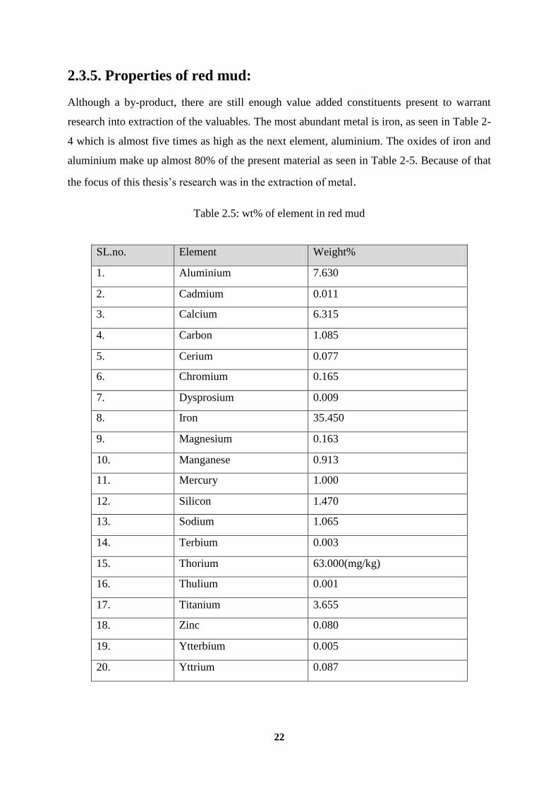
2.3.5. Properties of red mud:
Although a by-product, there are still enough value added constituents present to warrant
research into extraction of the valuables. The most abundant metal is iron, as seen in Table 2-
4 which is almost five times as high as the next element, aluminium. The oxides of iron and
aluminium make up almost 80% of the present material as seen in Table 2-5. Because of that
the focus of this thesis’s research was in the extraction of metal.
Table 2.5: wt% of element in red mud
SL.no. Element Weight%
1. Aluminium 7.630
2. Cadmium 0.011
3. Calcium 6.315
4. Carbon 1.085
5. Cerium 0.077
6. Chromium 0.165
7. Dysprosium 0.009
8. Iron 35.450
9. Magnesium 0.163
10. Manganese 0.913
11. Mercury 1.000
12. Silicon 1.470
13. Sodium 1.065
14. Terbium 0.003
15. Thorium 63.000(mg/kg)
16. Thulium 0.001
17. Titanium 3.655
18. Zinc 0.080
19. Ytterbium 0.005
20. Yttrium 0.087
23
CHAPTER: 3
MATERIALS AND METHODS

24
3.1. Material:
3.1.1. Red mud: In this work red mud was supplied by NALCO India Ltd. The chemical
analyses of red mud are given in Table 3.1. Red mud is classified by EC as a non hazardous
waste (commission decision 2000/532/EC) however its small particle size (dust like, mean
particle size 0.49 micro meter), high alkalinity and large amounts (30 to 35 million tons per
year on dry basis world).
Fig. 3.1: Red mud
Table 3.1: Chemical analysis of red mud
SL.NO. COMPOUND Wt.%
1. Fe2O3 47.49
2. Al2O3 21.07
3. SiO2 5.72
4. Na2O 3.78
5. CaO 1.36
6. TiO2 4.86
7. LOI 13.49

25
3.1.2 Aluminium powder: Aluminium powder was provided by DISIR LAB,
RAJGANGPUR.
Fig. 3.2: Aluminium powder
3.1.3 Coke: 100 mesh size, carbon powders were added in stoichiometric amounts for the
reducible oxides.
Fig. 3.3: Coke

26
3.1.4 Lime: Lime (CaCO3) is also provided by DISIR LAB, RAJGANGPUR.
Fig. 3.4: Lime
3.2 HOMOGENISATION: All the ingredients are mixed and homogenised in pulveriser
taking the mixes in Tungsten Carbide crucible with Tungsten carbide balls.
Fig. 3.5: Pulveriser

27
3.3 Work plan:
REDMUD+REDUCTANT+FLUX
HOMOGENIZATION
GRINDING
METAL NON-METAL
THERMAL PLASMA TREATMENT
MAGNETIC SEPERATION
Fig. 3.6: Work plan for experiment
3.4 Material preparation:
The homogenised mixes as per compositions given in Table no 3.2, 3.3 and 3.4 are mixed
with distilled water (10-12 parts) in a 5kg mixer for 20 minutes. Pellets having diameter 10-
15mm are made by hand rolling. The pellets are dried in an air oven for 2 hours to remove the
moisture. Now the samples are ready to feed in the crucible of plasma furnace. Argon was
used as ionising gas. Flow rate of Argon gas was 2.5 LPA.

28
Table 3.2: Composition of sample A
Table 3.3: Composition of sample B
Table 3.4: Composition of sample C
SL.NO Compound/Material Wt.% Wt in gram.
1. Red Mud 85 360
2. Coke 15 40
SL.NO Compound/Material Wt.% Wt in gram
1. Red Mud 75 562.5
2. Coke 10 75
3. Lime 10 75
4. Aluminium dross 5 37.5
SL.NO Compound/Material Wt.% Wt in gram
1. Red Mud 65 650
2. Coke 15 150
3. Lime 15 150
4. Aluminium dross 5 50

29
3.5. Plasma arc reactor:
The crucible where fusion was done made of graphite which worked as Cathode. The
crucible was put inside a rounded metallic pot lined with 60 % Alumina cast able. The
annular space between the graphite crucible and metallic pot was filled with bubbled
Alumina which works as a heat insulator. The Anode which runs vertically from the top
towards the cathode was made of Graphite with a 5mm coaxial hole runs throughout
facilitating to pass ionising gas. The gas flow was regulated with a flow meter. Both the
electrodes were connected with 20 KW generators which feed in 440 V AC. This device was
an export arc plasma reactor where initial arc was generated and plasma arc length was
controlled by moving the anode upward fitted with a rack and pinion system. The power was
controlled with a potentiometer fitted with the generator. Schematic diagram was given in
Fig.[15]
Fig. 3.7: Schematic diagram of plasma arc reactor
30
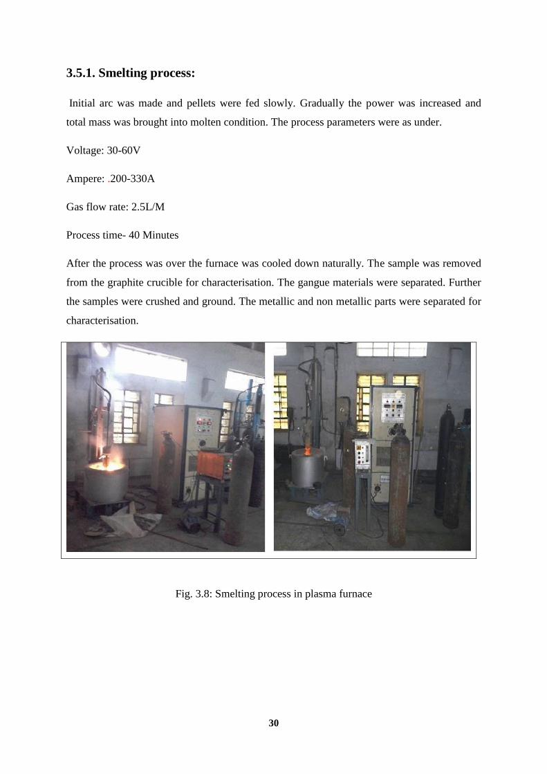
3.5.1. Smelting process:
Initial arc was made and pellets were fed slowly. Gradually the power was increased and
total mass was brought into molten condition. The process parameters were as under.
Voltage: 30-60V
Ampere: .200-330A
Gas flow rate: 2.5L/M
Process time- 40 Minutes
After the process was over the furnace was cooled down naturally. The sample was removed
from the graphite crucible for characterisation. The gangue materials were separated. Further
the samples were crushed and ground. The metallic and non metallic parts were separated for
characterisation.
Fig. 3.8: Smelting process in plasma furnace

31
Fig. 3.9: Smelting process
3.6. Material characterization:
3.6.1. Phase analysis by XRD: Phase analysis of Magnetic and non magnetic parts
were done by X -ray diffractometer using Panalytical Xpert pro system. Different
parameters were as under.
Table 3.5: Parameters of XRD
X-ray ceramic
Anode material copper
window beryllium
Filter Nickel
Kα1 1.54060 A
Kα2 1.54443
Voltage 45kv
Current 40mA
Detector proportional
Scanning start position (2θ) 10.0090
Scanning end position(2θ) 59.9890
Scanning step size (2θ) 0.02
Scanning step time (2θ) 0.4
Scanning type (2θ) continuous

32
It is a very compact unit where the x-ray generator, goniometer optics and recording system
are all encapsulate together. The goniometer is a precision one and facilitates rapid
measurement with high angular accuracy.
It is possible to do the measurement of powder samples in small quantity without any shaping
because of almost horizontal position of the sample holder surface. Therefore the vertical
goniometer has its own advantages in measuring these samples in addition to having
advantage of loading of the samples.
The ease of operation to select the scanning speed ranging between 60deg/min to 120deg/min
in six steps of constant speed is also an advantage in this equipment. This helps in selection
of operating conditions when the overall picture of an x-ray diffraction profile in an angular
range profile or full scale measurement is required.
3.6.1.1. Sample preparation:
Representative samples of slag were made by coning quartering and taken in pulviriser for grinding
below 20 micron. 0.71 gm of the ground slag sample was put on a aluminum disc having a groove of
15mm diameter, leveled and pressed with a glass slide. Operating condition was maintained as
mentioned earlier. Phases were identified using high score plus software.
Fig. 3.10: XRD machine

33
3.6.2. Micro structural Analysis by Optical Microscope:
Microstructural studies of Magnetic and non magnetic parts were done on polished section
under reflected light in a universal microscope. (Carl Zeiss, Axio Universal Research
Microscope with Image analyser.).
3.6.2.1. Sample Preparation:
Polish sections were prepared as per the standard methods. The samples were impregnated
with cold resin (Araldite and Hardener in 9:1 ratio) and evaluated in Vacuum desiccators for
30 minutes. Then the mounted samples were kept overnight to get hardened. The preliminary
polishing was done with carborundum paper of 120, 400 and 600 designations. The final
polishing was done on a special micromax polishing cloth attached to a rotating wheel where
alumina powder in water medium was used as the polishing medium. Finally the samples
were polished with o.1 micron diamond paste on paper. The polish sections were examined
under reflected light.
Fig. 3.11: Optical microscope

34
CHAPTER: 4
RESULT AND DISCUSSION

35
Operating condition during plasma processing shown in below table:
Table 4.1: Operating condition during processing
Sample no. Process time in
Min.
Power consumption
KW
Power consumption/kg in units
KW
A 40 12 40
B 30 10 31
C 26 8 25
4.1. Sample A (15% coke + 85% red mud):
Table 4.2: Result of sample A after processing
4.1.1. XRD:
(a) Magnetic:
Table 4.3 XRD analysis of sample A
Sample no. Major phases Minor phases
Sample A
(Magnetic)
Fe3C (Cohenite),Fe (Iron),
Tic (Khamrabaevite)
Fe2Ti (Iron Titanium)
SL.no. Total materials
fused
Recovery Magnetic part Non Magnetic part
1. 400 grams 300 grams 250grams 50 grams

36
Position [°2Theta] (Copper (Cu))
20 30 40 50
Counts
0
20
40
60
Cohenite
Iron T
itaniu
m (
2/1
)
Kham
rabaevite
Kham
rabaevite
Iron;
Cohenite
13_0614_PF RED MUD(MAGNATIC)
Fig. 4.1: XRD pattern of sample A
(b) Non-Magnetic part:
Position [°2Theta] (Copper (Cu))
20 30 40 50
Counts
0
50
100
Zeolit
e
Crist
obalit
e b
eta
hig
h
Coru
ndum
; Zeolit
e
Gra
phite 2
H
Herc
ynite
Coru
ndum
Herc
ynite
Coru
ndum
; H
erc
ynite
Coru
ndum
; Zeolit
e
Gra
phite 2
H;
Herc
ynite
Coru
ndum
Coru
ndum
; Zeolit
e
13_06_15_PF RED MUD(NON-MAGNATIC)
Fig. 4.2: XRD pattern of sample A

37
Table 4.4: XRD analysis of sample A
Sample no. Major phases Minor phases
Sample A (Non-
Magnetic)
Al2O3 (Corundum),C
(Graphite)
Al1.994Fe1.006O4(Hercynite),SiO2
(Zeolite),
4.2. Sample B (75% red mud + 10% coke + 10% lime + 5% aluminium powder):
Table 4.5: Result of sample B after processing
SL.no. Total material fused
(gram)
Recovery
(grams)
Magnetic part
(grams)
Non-Magnetic part
(grams)
1. 500 380 310 70
4.2.1. XRD
(a) Magnetic part:
Position [°2Theta] (Copper (Cu))
20 30 40 50
Counts
0
50
100
Herc
ynite
Pero
vsk
ite
Gro
ssula
r
Herc
ynite
Herc
ynite;
Pero
vsk
ite
Pero
vsk
ite;
Gro
ssula
r
Pero
vsk
ite
Herc
ynite;
Pero
vsk
ite;
Gro
ssula
r
Herc
ynite;
Pero
vsk
ite;
Gro
ssula
r
13_08_39_PF REDMUD AFTER INCIPIENT FUSION(MAGNETIC)
Fig.4.3: XRD pattern of sample B

38
Table 4.6: XRD analysis of sample B
(b) Non –Magnetic part:
Position [°2Theta] (Copper (Cu))
20 30 40 50
Counts
0
50
100
Herc
ynite;
Akerm
anite (
Fe-c
onta
inin
g)
Isco
rite
Herc
ynite
Herc
ynite;
Iron;
Akerm
anite (
Fe-c
onta
inin
g)
Akerm
anite (
Fe-c
onta
inin
g)
Herc
ynite;
Akerm
anite (
Fe-c
onta
inin
g)
Herc
ynite
13_08_40_PF REDMUD(NONMAGENETIC)
Fig 4.4 XRD pattern of sample B for non magnetic material
Table 4.7: XRD analysis of sample B
Sample no. Major phases Minor Phases
Sample B (Magnetic
part)
Al2FeO4 (Hercynite), TiO3Ca
(Perovskite)
Al2Ca3O12Si3
(Grossular)
Sample no. Major phases Minor phases
Sample B(non-
Magnetic part) Al1.1993Fe0.996O4(Hercynite)
Fe7O10Si (Iscorite),Ca2Fe0.45Mg0.55O7Si2
(Akermanite Fe-containing)

39
4.3. Sample C (Result of 65% red mud + 15% coke + 15% lime +5% aluminium
powder):
Table 4.8: Result of sample C after processing
Sl. No. Total material fused
in gram
Recovery in
gram
Magnetic part in
gram
Non-magnetic part in
gram
Sample C 1000 820 600 220
4.3.1. XRD:
(a) Magnetic part:
Position [°2Theta] (Copper (Cu))
20 30 40 50
Counts
0
50
100
Fayalit
e
Sodiu
m T
ect
o-a
lum
osi
licate
; Fayalit
eSodiu
m T
ect
o-a
lum
osi
licate
; D
icalc
ium
Diir
on(I
II)
Oxid
e
Sodiu
m T
ect
o-a
lum
osi
licate
Fayalit
e;
Dic
alc
ium
Diir
on(I
II)
Oxid
e
Sodiu
m T
ect
o-a
lum
osi
licate
Fayalit
e
Sodiu
m T
ect
o-a
lum
osi
licate
; D
icalc
ium
Diir
on(I
II)
Oxid
eD
icalc
ium
Diir
on(I
II)
Oxid
e
Fayalit
eFayalit
eTitaniu
m C
arb
ide (
1/1
); D
icalc
ium
Diir
on(I
II)
Oxid
eSodiu
m T
ect
o-a
lum
osi
licate
; Fayalit
e;
Dic
alc
ium
Diir
on(I
II)
Oxid
e
Sodiu
m T
ect
o-a
lum
osi
licate
; Fayalit
e;
Dic
alc
ium
Diir
on(I
II)
Oxid
e
Titaniu
m C
arb
ide (
1/1
)
Iron T
itaniu
m (
2/1
); S
odiu
m T
ect
o-a
lum
osi
licate
; D
icalc
ium
Diir
on(I
II)
Oxid
eSodiu
m T
ect
o-a
lum
osi
licate
; D
icalc
ium
Diir
on(I
II)
Oxid
e
Fayalit
e;
Dic
alc
ium
Diir
on(I
II)
Oxid
eIr
on;
Sodiu
m T
ect
o-a
lum
osi
licate
; Fayalit
e;
Dic
alc
ium
Diir
on(I
II)
Oxid
e
Fayalit
e
Sodiu
m T
ect
o-a
lum
osi
licate
; Fayalit
e;
Dic
alc
ium
Diir
on(I
II)
Oxid
e
Iron T
itaniu
m (
2/1
); F
ayalit
e;
Dic
alc
ium
Diir
on(I
II)
Oxid
e
13_7_54_P.F RED MUD(MAGNETIC)
Fig. 4.5: XRD pattern of sample C for magnetic material

40
Table 4.9: XRD analysis of sample C for magnetic materials
Sl.no. Major phases Minor phases
Sample
(magnetic part)
C
TiC(Titanium carbide),Si2O6NaAl
(SodiumTecto-alumosilicate)
Fe2Ti (Iron Titanium), Fe(Iron),Fe2O4Si
(Fayalite),Ca2Fe2O5 (Dicalcium diron
oxide)
(b) Non- Magnetic part:
Position [°2Theta] (Copper (Cu))
20 30 40 50
Counts
0
100
200
Gro
ssite
Gro
ssite
Gro
ssite
Gro
ssite
Gra
phite 3
R
Gro
ssite
Gro
ssite;
Gehle
nite
Calc
ium
Dia
lum
inate
- M
eta
stable
Gro
ssite;
Calc
ium
Dia
lum
inate
- M
eta
stable
Gehle
nite
Gro
ssite
Gro
ssite;
Gehle
nite;
Calc
ium
Dia
lum
inate
- M
eta
stable
Gro
ssite;
Hem
atite
Gro
ssite;
Gehle
nite;
Calc
ium
Dia
lum
inate
- M
eta
stable
Gro
ssite;
Gehle
nite
Gro
ssite;
Gehle
nite;
Calc
ium
Dia
lum
inate
- M
eta
stable
Gro
ssite
Gro
ssite;
Calc
ium
Dia
lum
inate
- M
eta
stable
Gro
ssite
Gro
ssite
Gro
ssite;
Gra
phite 3
R;
Gehle
nite;
Calc
ium
Dia
lum
inate
- M
eta
stable
Gro
ssite;
Calc
ium
Dia
lum
inate
- M
eta
stable
Gro
ssite;
Gehle
nite;
Calc
ium
Dia
lum
inate
- M
eta
stable
Gro
ssite;
Gehle
nite
Gro
ssite;
Gehle
nite
Gro
ssite;
Gehle
nite
Gro
ssite;
Gra
phite 3
R;
Gehle
nite;
Hem
atite
13_7_55_P.F RED MUD (NON-MAGNETIC)
Fig. 4.6: XRD pattern of sample C for non magnetic materials
Table 4.10: XRD analysis of sample C for non magnetic materials
Sl.no. Major phases Minor phases
Sample C (Non-
Magnetic part)
Al4CaO7( Grossite),C (Graphite
3R),Al2Ca2O7Si (Gehlenite)
Al2CaO4(Calcium dialuminate-
metastable),Fe2O3(Hematite)
41
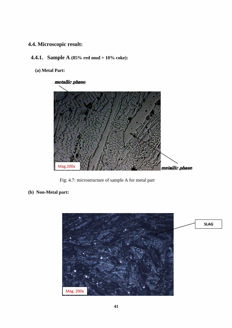
4.4. Microscopic result:
4.4.1. Sample A (85% red mud + 10% coke):
(a) Metal Part:
Fig: 4.7: microstructure of sample A for metal part
(b) Non-Metal part:
Mag.200x
XX
Mag. 200x
SLAG

42
Fig.4.8: Microstructure of sample A for non metallic part
4.4.2 Sample B (75% red mud + 10% coke+ 10% lime +5% aluminium powder):
(a) Metal Part:
Fig. 4.9: Microstructure of sample B for metallic part
(b) Non- Metal part:
GEHLENITE
Fig. 4.10: Microstructure of sample B for non metallic part
Mag. 200x
Mag. 200x

43
4.4.3. Sample C (65% red mud + 15% coke+ 15% lime +5% aluminium powder):
(a) Metal Part:
Fig. 4.11: Microstructure of sample C for metallic part
(b)Non-Metal part:
Mag. 200x
Mag. 200x
GEHLENITE
44
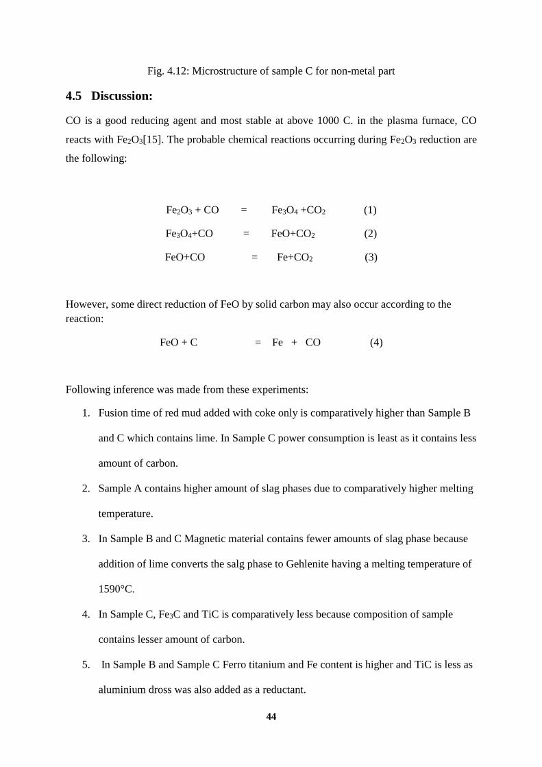
Fig. 4.12: Microstructure of sample C for non-metal part
4.5 Discussion:
CO is a good reducing agent and most stable at above 1000 C. in the plasma furnace, CO
reacts with Fe2O3[15]. The probable chemical reactions occurring during Fe2O3 reduction are
the following:
Fe2O3 + CO = Fe3O4 +CO2 (1)
Fe3O4+CO = FeO+CO2 (2)
FeO+CO = Fe+CO2 (3)
However, some direct reduction of FeO by solid carbon may also occur according to the
reaction:
FeO + C = Fe + CO (4)
Following inference was made from these experiments:
1. Fusion time of red mud added with coke only is comparatively higher than Sample B
and C which contains lime. In Sample C power consumption is least as it contains less
amount of carbon.
2. Sample A contains higher amount of slag phases due to comparatively higher melting
temperature.
3. In Sample B and C Magnetic material contains fewer amounts of slag phase because
addition of lime converts the salg phase to Gehlenite having a melting temperature of
1590°C.
4. In Sample C, Fe3C and TiC is comparatively less because composition of sample
contains lesser amount of carbon.
5. In Sample B and Sample C Ferro titanium and Fe content is higher and TiC is less as
aluminium dross was also added as a reductant.

45
CHAPTER: 5
CONCLUSION

46
5.1. Conclusion:
This process seems to be viable for extraction of Iron and Ferrotitanium from red mud which
is a potential threat for its disposal. Also the slag generated from this process which is
Gehlenite can be used for making refractories or can be used in Port land slag cement after
granulation.
5.2. Scope for Future work:
1. Although alkali was removed from the red mud with the addition of warm water but
alkali could not be removed completely. This alkali can be recovered completely
before fusing these materials.
2. Also illemanite can be blended for better recovery of ferrotitanium.
3. Bigger trial can be done in a continuous plasma furnace for better separation of slag
And metal and having better cost economics.
47
References:
1. Science direct: utilization of red mud as a stabilization material for the preparation of clay
liners by Ekrem kalkan.
2. Chandra, Satish. Waste Materials Used in Concrete Manufacturing. Westwood, N.J.,
U.S.A.: Noyes Publications, 1997. Print.
3. Fly Ash. Fly Ash, N.P., n.d. Web. 01 Dec. 2012. <http://www4.uwm.edu/cbu/>.
4. Gura, David.” Toxic red sludge spill from Hungarian aluminium plant ‘an ecological
disaster”
October 5, 2010.
5. Hungarian Chemical Sludge Spill Reaches Danube. BBC. October 7, 2010.
6. Kogel, Jessica Elzea. Industrial Minerals & Rocks: Commodities, Markets, and
Uses.Littleton, CO: Society for Mining, Metallurgy, and Exploration, 2006. Print.
7. Mohan, D.; Pittman, CU. (Apr 2007). "Arsenic removal from water/wastewater using
adsorbents--A critical review". J Hazard Mater 142 (12): 153
8. Peretti, Daniel. The Modern Prometheus: The Persistence of an Ancient Myth in the
Modern World. N.p.: Indiana University, 2008. Print.
9. Pontikes., Y. "Red Mud Applications." Red Mud Project, 14 Mar. 2005. Web.
<http://www.redmud.org/Applications.html>.
10. Staley, Anthony K., Ph.D. An Investigation into the Pyrometallurgical and
Electrometallurgical Extraction of Iron from "red Mud" Generated in the Processing of
Bauxite Ores. Golden, CO: Colorado School of Mines, 2002. Print.
11. The KolontÃr Red Mud Dam Failure (Hungary). The Kolontár Red Mud Dam Failure
(Hungary). N.P., n.d. Web. 3 Sept. 2012. <http://www.wise-uranium.org/mdafko.html>.

48
12. Zhang-long, YU, Chen Yong-jian, Wang Yong-xia, and Wan Ping-yu. Red-mud
Treatment Using Oxalic Acid by UV Irradiation Assistance. School of Science, Beijing
University of Chemical Technology, Department of Mineral Resource and Metallurgical
Materials, PR China, Beijing General Research Institute for Non-Ferrous Metals, The
Nonferrous Metal Society of China, n.d. Web. 2 Oct. 2012.
13. Dugan, Brandon. Recycling of Bag-House Dust from Foundry Sand through Chemical
and Physical Separation. Golden, CO: Colorado School of Mines, 2011. Print.
14. “LIGHT METALS” 2011 Edited by Stephen J. Lindsay.
15. International journal of minerals, metallurgy and material volume 19, number 8, Aug
2012, Page 697, DOI: 1007/S12613-012-0613-3.
16. Recovery of value – added products red mud and foundry BAG-House dust by keegan
Hmmond.
17. CR3 communication: red mud – “A resource or a waste.” Jom, 2013
18. American chemical science journal 4(3): 255-799.2014 progress of red mud utilizatio:an
overview.
19. Boily, Robert, Ph.D. Twenty Cases of Red Hazard, An Inventory of Ecological Problems
Caused by Bauxite Residue from Alumina Production. Larval, Quebec, Canada: Inforex,
2012. Print.
20. “Aluminium”, US Geological survey, mineral commodity summaries (Washington,D.C.
USGS 2012), MINERALS. USGS. Gov/minerals/pubs/commodity/aluminium/mes-1012-
alumi.pd/.
21. J.Fursman, J.E. Mauser, M.O. Bulter, and W.A. Stickney, utilization of red mud residue
from alumina production , U.S. bureau of mines report of investigation 7454 (1970).
22. R. Piga, F. Pochetti, and L. Stoppa, JOM, 45 (35) (1993), pp. 5559.
23. W. Braithwait, GB patent 2078211-A (January 1982).
21. Agency of Ind. Sci. Tech., J. patent 52152896-A (December 1977).
24. S. Guccione, Eng. Min. J., 172 (34) (1971), pp. 136138.

49
25. N. Dakatos, M. Miskei, and J. Szolnoki, DE patent 2,747,436 (May 1978). 21. M.
Cresswell, and D.J. Milne, AU patent 88102 (September 1981).
26. R. Vachon, R. Tyagi; J-C. Auclair, and K.J. Wilkinson, Environ. Sci. Technol., 28 (26)
(1994), pp. 2630.
27. B. Mishra, A. Staley, and D. Kirkpatrick, Recycling and Waste Treatment in Mineral and
Metal Processing: Technical & Economic Aspects: Vol.2, ed. B. Björkman, C. Samuelsson,
and J.-O. Wikström (Warren dale, PA: TMS, 2002), pp. 567576.
28. K. Hammond, B. Mishra, D. Apelian, and B. Blanpain. JOM, 65 (28) (2013), pp. 340-
341.
29. W.G. Rumbold; Bauxite and Aluminum; 1925; Imperial Institute, London; Hazell Watson
& Viney Ld., London.
30. Various Websites: Company Sites from Alcoa, Nabalco, Renyolds Kaiser, US Geological
Serveys Site, and the Mineral Council of Australia.
31. A.R. Burkin. Production of Aluminum and Alumina. 1987. Published on behalf of the
Society of Chemical Industry by John Wiley &Sons. Chichester, New York, Brisbane,
Toronto, Singapore.
32. F.King; Aluminum and its Alloys; Ellis Hornwood Limited; Chichester, West Sussex,
England; 1987.
33. P.M. Prasad; Maneesh Singh; Problems in the Disposal and Utilization of Red Muds; The
Banaras Metallurgist, Vol. 14 & 15, 1997: pp. 127-140.
34. February 2000, Technology Roadmap Bauxite Residue Treatment and Utilization,
Summary of Workshop Prepared by Energetics, Inc.
35. Luigi Piga; Fausto Pochetti; Luisa Stoppa; Recovering Metals from Red Mud Generated
During Alumina Production; Journal of Metals, pp. 54-59; November 1993.
36. P.M. Prasad; J.M. Sharma; V. Vishwanathan; A.K.Nandi; Maneesh Singh; Production of
Bricks/Stabilized Blocks From Red Mud; Deparment of Metallurgical Engineering, Institute
of Technology, Banaras Hindu University, Varanasi 221005; Proceeding of Interactive

50
Meeting on the Bauxite and Alumina (BAUXAL-96); Feb 1996, Allied Publishers New
Delhi, pp. 387-396.
37.Habashi, Fathi. "Karl Josef Bayer and His Time* - Part 1." Proc. of International
Committee for the Study of Bauxite, Alumina, and Aluminium (ICSOBA), National
Aluminum - Magnesium Institute, Saint Petersburg, Russia. N.p.: n.p., 2004. N. pag. Print.
38. Fathi Habashi. A Textbook of Hydrometallurgy. 1993. Métallurgie Extactive Québec,
Canada.