vag krv ball check valve · the vag krv ball check valve is a fully flanged non-return val-ve and...
TRANSCRIPT

VAG KRV Ball Check Valve
Operating and Maintenance Instructions
2449 KAT-B Edition1 06-18
VAG Operation and Maintenance Instructions • 2
We reserve the right to make technical changes and use similar or higher-quality materials. Drawings are non-binding.
1 Inhalt
1 General 3
1.1 Safety 3
1.2 Proper use 3
2 Transport and storage 3
2.1 Transport 3
2.2 Storage 3
3 Product and function description 3
3.1 Features and function description 3
3.2 Application 3
3.3 Permissible and impermissible modes of operation 4
4 Installation into the pipeline 4
4.1 Conditions required on site 4
4.2 Installation location 4
4.2.1 Stable flow 5
4.2.2 Flow velocity 5
4.3 Installation position 5
4.4 Assembly instructions, fittings 6
5 Putting the valve into operation 6
5.1 Visual inspection 6
5.2 Function check and pressure test 6
6 Maintenance and repair 7
6.1 General safety instructions 7
6.2 Inspection and operating intervals 7
6.3 Maintenance and replacement of parts 7
6.3.1 Inspection of the shut-off ball 7
6.3.2 Leakage on the cover seal 7
6.3.3 Recommendation for replacement of parts 7
7 Trouble-shooting 8
8 Contact 8

VAG Operation and Maintenance Instructions • 3
Picture 1: Function of the VAG KRV Ball Check Valve
1 General
1.1 Safety
These Operating and Maintenance Instructions must be obser-ved and applied at all times along with the general “VAG Instal-lation and Operating Instructions for Valves”. Arbitrary altera-tions of this product and of the parts supplied with it are not allowed. VAG will not assume any liability for consequential da-mage due to non-compliance with these instructions. When using this valve, the generally accepted technical rules and standards (e.g. DIN standards, DVGW instruction sheets, VDI guidelines etc.) must be observed. The installation must only be carried out by qualified staff. For further technical information, such as dimensions, materials and applications, please refer to the respective documentation (KAT 2449-A etc.).
1.2 Proper useThe VAG KRV Ball Check Valve is intended for installation in pipelines. Its standard version is suitable for admitting the flow of the medium in one direction in pressurized pipelines and for automatically preventing the backflow of the medium.
For information about the technical limits of operation (e.g. ope-rating pressure, medium, temperature) please, refer to the pro-duct-related documentation (KAT 2449-A).
The manufacturer’s written approval must be obtained for any deviating operating conditions and applications.
2 Transport and storage
2.1 TransportFor transportation to its installation site, the valve must be pa-cked in stable packaging material suitable for the size of the valve. The packaging must ensure that the valve is protected against atmospheric influences and external damage.
When the valve is shipped under specific external climatic con-ditions (e.g. overseas transport), it must be specially protected by wrapping it in plastic film and a desiccant must be added.
The VAG KRV Ball Check Valve should be transported resting on its side.
The factory-applied corrosion protection and any assemblies need to be specially protected.
2.2 StorageThe VAG KRV Ball Check Valve should be stored resting on its side. The elastomeric parts (seals) must be protected against direct sunlight as otherwise their long-term sealing function cannot be guaranteed.
Store the valve in a dry and well ventilated place and avoid di-rect exposure to radiant heat coming from radiators.
Protect the components essential for proper function, such as the shut-off ball, against dust and other dirt from the outside by suitable covers.
3 Product and function description
3.1 Features and function descriptionThe VAG KRV Ball Check Valve is a fully flanged non-return val-ve and can therefore be used between two pipeline flanges and as an end-of-line valve without counter flange at full operating pressure.
The rubber-coated ball runs inside the special inner geometry of the body and moves to its upper end position in the body when the medium flows through it (see Picture 1).
A free, unobstructed cross-sectional area of flow is achieved in the body when the shut-off ball is in the open position.
The displacement of the ball depends on the flow velocity of the medium. A defined minimum velocity of the medium is required to move the ball into a stable end position in the body and to cause it to rest on the body cover. The specific density of the ball is higher than that of the medium around it. When the flow stops, this “sinking ball” lowers due to its own weight and then rests on the sealing seat.
When installed horizontally in the pipeline (see Picture 2), the ball check valve is slightly open as the ball rests in its neutral position on the bottom of the body and as there is a small gap between the shut-off ball and the seat because of this.
When installed vertically in the pipeline, the ball rests centrally in the valve seat and thus immediately achieves its optimum sealing effect.
A back pressure of at least 5 mWC is needed for full sealing.
3.2 ApplicationDue to the NBR sealing materials used, the VAG KRV Ball Check Valve is suitable for the following media:
Raw and cooling water, municipal wastewater, weak acids and alkaline solutions
The use in other media that are not specified here can lead to the destruction of the rubber coating of the ball and of the O-rings.

VAG Operation and Maintenance Instructions • 4
Please consult the manufacturer if you intend to use the valve in other operating conditions and for other applications.
3.3 Permissible and impermissible modes of operation
The maximum operating temperatures and opera-ting pressures specified in the technical documenta-tion (KAT 2449-A) must not be exceeded. The pres-sure applied to the closed non-return valve must not exceed its nominal pressure.
The highest permissible flow velocity (at stable flow) is in accordance with EN 1074-1:
Valves with PN 10: 3 m/s
Valves with PN 16: 4 m/s
When the valve is used in turbulent flow (e.g. when installed downstream of bends, expansion adapters or immediately downstream of a pump flange), a damping zone of sufficient length (recommended length: at least 5 x DN) must be provi-ded.
4 Installation into the pipeline
4.1 Conditions required on siteWhen the valve is installed between pipeline flanges, these must be coplanar and in alignment. If the pipelines are not in alignment, they must be aligned before the installation of the valve as otherwise this may result in impermissibly high loads acting on the body, which may eventually even cause the body to break.
When installing the valve into the pipeline, make sure it is tensi-on-free. No pipeline forces must be transferred to the valve.
The space between the flanges should be wide enough to pre-vent damage to the coating of the flange gasket frames during installation. If works causing dirt (e.g. painting, bricklaying or concrete work) are performed close to the valve, it must be ef-fectively protected by an adequate cover.
4.2 Installation locationDThe location selected for the installation of the valve must en-sure that enough space is available for its operation (disassem-bly of the shut-off ball), later function checks and maintenance work (e.g. cleaning of the valve). If the valve is installed outdoo-rs, it must be effectively protected against extreme atmospheric influences, such as the formation of ice, by an adequate cover.
If possible, the valve should not be installed immediately down-stream of a pump (1). When the valve is installed in a vertical pipeline (2), a damping zone of sufficient length (at least 5 x DN) should be provided. An inspection valve (we recommend a kni-fe-gate valve) should be installed immediately downstream of the ball check valve to allow for maintenance and repair work
Picture 2: Horizontal and vertical installation
Picture 3: Selection of the installation location
1 2 3
Min. 5 x DN
Min. 3 x DN

VAG Operation and Maintenance Instructions • 5
Picture 4: Installation positions
later on. It must be ensured that the flow velocity is high enough so that solid matter is discharged from the ascending pipe and cannot collect in the non-return valve when the pump is swit-ched off.
We recommend installation in the horizontal area of the pump line (3) as this reduces the risk of excessive soiling of the non-return valve by solid matter.
Several factors regarding the position of the valve have to be observed to ensure the trouble-free function and a long service life of the non-return valve:
4.2.1 Stable flowA constant, steady flow ensures the stable position of the shut-off ball in its end position even at higher flow velocities (see section 3.3). To achieve steady flow, a straight damping zone of a length of 5 x DN should be provided upstream of the non-re-turn valve (Pictures 3 and 4).
If a damping zone as shown in Picture 4 cannot be provided, turbulences in the flow may cause vibrati-on on the shut-off ball and reduce its service life. Should installation directly at the pump flange be in-evitable, the KRV Ball Check Valve should be instal-led – depending on the outflow characteristics of the medium downstream of the pump – so that the shut-off ball is located in the no-flow zone (see Picture 4).
4.2.2 Flow velocityThe VAG KRV Ball Check Valve is suitable for operation at ma-ximum flow velocity according to EN 1074-1 (see section 3.3).
This requires installation with an upstream damping zone (Picture 4).
Due to the special operating principle of the VAG KRV Ball Check Valve (sinking ball principle), it must be ensured that the minimum flow velocity inside the valve is high enough.
This minimum flow velocity ensures the safe and stable position of the shut-off ball in its end position in the body.
If the flow velocity is too low, this will lead to uncontrolled pen-dular movements of the shut-off ball inside the body and to loud noise and eventual destruction of the rubber coating and the cover coating as a result.
The minimum flow velocities required for the VAG KRV Ball Check Valve are:
a) In the horizontal pipeline: at least 1.5 m/s
b) In the vertical pipeline: at least 2 m/s
The higher flow velocity in the vertical pipeline is necessary to reliably remove solids from this area.
4.3 Installation positionThe VAG KRV Ball Check Valve can be installed in horizontal and vertical pipelines with an angle of ascent of up to 90°. Al-ways remember to observe the arrow indicating the flow direc-tion on the valve body when you install the valve.
The valve will not function in any other installation positions (Picture 5).
When the valve is used in wastewater containing so-lids, horizontal installation should be preferred as this prevents the valve from becoming clogged by deposits.

VAG Operation and Maintenance Instructions • 6
Permissible Permissible Permissible
Impermissible Impermissible
Impermissible Impermissible Impermissible
Impermissible
Picture 5: Permissible and impermissible installation positions of the VAG KRV Ball Check Valve
4.4 Assembly instructions, fittingsBefore assembling the valve check it for any damage that may have occurred during transport and storage. Protect the valve against dirt from the construction site by an adequate cover un-til its installation. When the valve is installed, its functional parts must be free from dust and dirt. VAG does not assume any lia-bility for consequential damage caused by dirt, shot-blasting gravel residues etc.
Before the installation of the valve, the shut-off ball should be checked for operability. When the valve is repainted later on, no paint must be applied to its functional parts.
Suitable lifting tackles such as handling and lifting devices must be available for the assembly of the VAG KRV Ball Check Valve.
For the connection of the valve to the pipeline flanges, hexago-nal screws and nuts with washers are to be used in the through holes from flange to flange.
Tighten the screws evenly and in diagonally opposite sequence to prevent unnecessary tension and cracks or breaks resulting therefrom.
The pipeline must not be pulled towards the valve. If the gap between the valve and the flange is too large, this should be compensated by thicker seals. Pipeline forces must only be transmitted to the valve in compliance with the specifications of
EN 1074-3.
We recommend the use of steel-reinforced seals to DIN EN 1514-1 Form IBC. If raised face flanges are used, these seals are mandatory.
5 Putting the valve into operation
5.1 Visual inspectionBefore putting the valve and the equipment into operation, per-form a visual inspection of all functional parts. Check whether all bolted connections have been properly fastened.
5.2 Function check and pressure testPrior to the installation of the valve, its functional parts (shut-off ball) have to be completely opened and closed at least once and checked for operability.
Caution!! The pressure applied to the closed valve must not exceed its nominal pressure (see Table 1 below). When a pressure test in the pipeline is per-formed with a pressure exceeding the admissible nominal pressure in the closing direction of the non-return valve, the shut-off ball can be easily opened or removed, if required, to prevent excessive strain on the elastomeric parts.
VAG Operation and Maintenance Instructions • 7
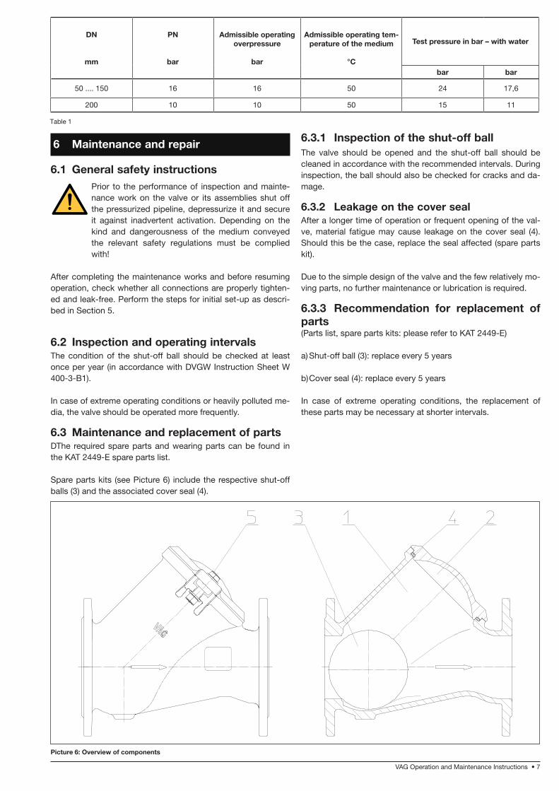
Picture 6: Overview of components
DN
mm
PN
bar
Admissible operating overpressure
bar
Admissible operating tem-perature of the medium
°C
Test pressure in bar – with water
bar bar
50 .... 150 16 16 50 24 17,6
200 10 10 50 15 11
Table 1
6 Maintenance and repair
6.1 General safety instructionsPrior to the performance of inspection and mainte-nance work on the valve or its assemblies shut off the pressurized pipeline, depressurize it and secure it against inadvertent activation. Depending on the kind and dangerousness of the medium conveyed the relevant safety regulations must be complied with!
After completing the maintenance works and before resuming operation, check whether all connections are properly tighten-ed and leak-free. Perform the steps for initial set-up as descri-bed in Section 5.
6.2 Inspection and operating intervalsThe condition of the shut-off ball should be checked at least once per year (in accordance with DVGW Instruction Sheet W 400-3-B1).
In case of extreme operating conditions or heavily polluted me-dia, the valve should be operated more frequently.
6.3 Maintenance and replacement of partsDThe required spare parts and wearing parts can be found in the KAT 2449-E spare parts list.
Spare parts kits (see Picture 6) include the respective shut-off balls (3) and the associated cover seal (4).
6.3.1 Inspection of the shut-off ballThe valve should be opened and the shut-off ball should be cleaned in accordance with the recommended intervals. During inspection, the ball should also be checked for cracks and da-mage.
6.3.2 Leakage on the cover sealAfter a longer time of operation or frequent opening of the val-ve, material fatigue may cause leakage on the cover seal (4). Should this be the case, replace the seal affected (spare parts kit).
Due to the simple design of the valve and the few relatively mo-ving parts, no further maintenance or lubrication is required.
6.3.3 Recommendation for replacement of parts(Parts list, spare parts kits: please refer to KAT 2449-E)
a) Shut-off ball (3): replace every 5 years
b) Cover seal (4): replace every 5 years
In case of extreme operating conditions, the replacement of these parts may be necessary at shorter intervals.
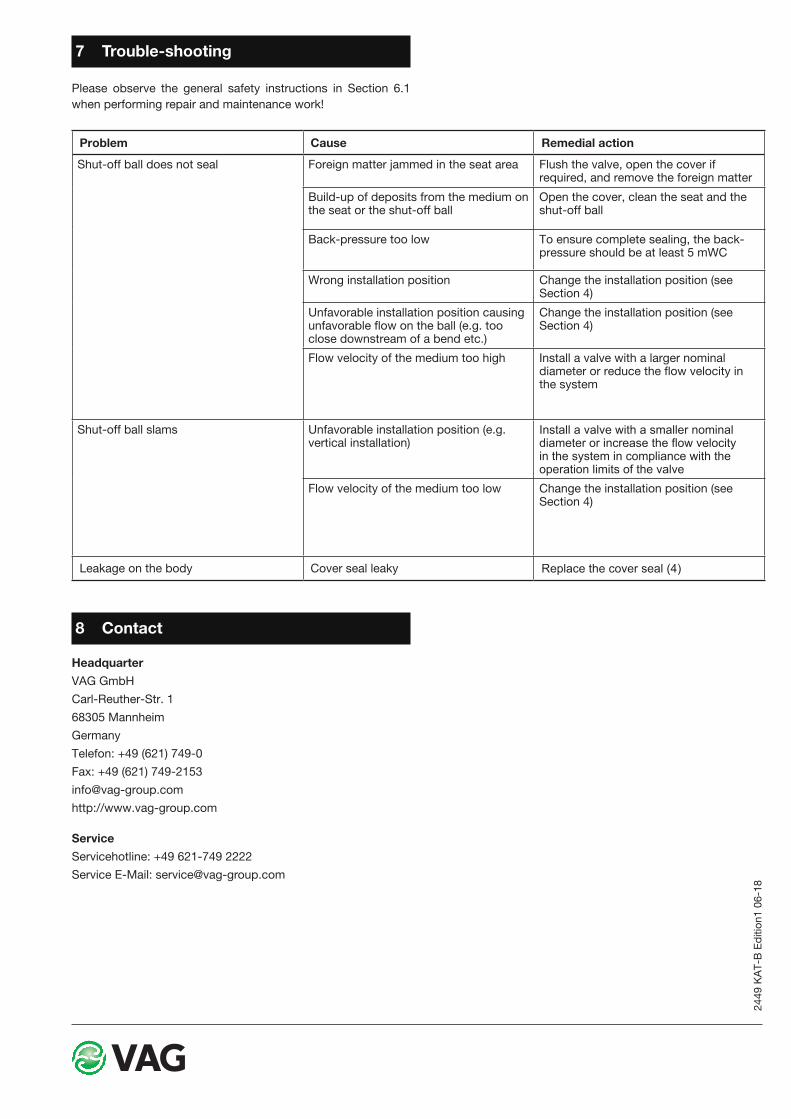
Problem Cause Remedial action
Shut-off ball does not seal Foreign matter jammed in the seat area Flush the valve, open the cover if required, and remove the foreign matter
Build-up of deposits from the medium on the seat or the shut-off ball
Open the cover, clean the seat and the shut-off ball
Back-pressure too low To ensure complete sealing, the back-pressure should be at least 5 mWC
Wrong installation position Change the installation position (see Section 4)
Unfavorable installation position causing unfavorable flow on the ball (e.g. too close downstream of a bend etc.)
Change the installation position (see Section 4)
Flow velocity of the medium too high Install a valve with a larger nominal diameter or reduce the flow velocity in the system
Shut-off ball slams Unfavorable installation position (e.g. vertical installation)
Install a valve with a smaller nominal diameter or increase the flow velocity in the system in compliance with the operation limits of the valve
Flow velocity of the medium too low Change the installation position (see Section 4)
Leakage on the body Cover seal leaky Replace the cover seal (4)
2449
KA
T-B
Edi
tion1
06-
18
7 Trouble-shooting
Please observe the general safety instructions in Section 6.1 when performing repair and maintenance work!
8 Contact
Headquarter VAG GmbHCarl-Reuther-Str. 168305 Mannheim GermanyTelefon: +49 (621) 749-0Fax: +49 (621) [email protected]://www.vag-group.com
ServiceServicehotline: +49 621-749 2222Service E-Mail: [email protected]