vae-1-mpm1 - midian electronics voice alarm encoder with lone worker & man ... radio must be...
TRANSCRIPT

1
VAE-1-MPM1
Voice Alarm Encoder with Lone Worker & Man-Down
Manual Revision: 2014-11-30 Covers Software Revisions: VS-1XXX: 01.53.00 & Higher Covers Hardware Revisions: VS-MPP1: D & Higher This manual supports the following radios: North America: CDM-750, CDM-1250, CDM-1550-LS+ EMEA Region: GM-140, GM-160, GM-340, GM-360, GM-380, GM-640, GM-660, GM-1280 Asia: GM-328, GM-338, GM-338-LS, GM-339, GM-398, GM-399, MCX-720, MCX-760, MCX-780 Latin America: PRO-3100, PRO-5100, PRO-7100, PRO-7200

2
HARDWARE SPECIFICATIONS Operating Voltage 4.75-8.2 VDC Operating Current Power Save Mode (COR Operation) 2.5 mA typical Power Save Mode (VOX Operation) 10 mA typical Normal Operation 17.5 mA typical Average w/COR Power Save (80-10-10 cycle) <5 mA Average w/COR Power Save (90-5-5 cycle) <4 mA Operating Temperature -30 - +60 C Frequency Response 300-3000 Hz Input Impedance >45 k Input Level (TX) 0.05-2.5 VPP Input Level (RX) 0.05-2.5 VPP Audio Output Impedance < 1200 Ohm
INSTALLATION OVERVIEW
1. Test the radio for functionality. 2. Program the radio per the Radio Programming Section of this manual. 3. Install the unit into the radio per the Hardware Installation Section of this manual. 4. Program the unit per the Product Programming Section of this manual. Note: Midian is not responsible for any damage/loss resulting from the use of Midian’s products.

3
GENERAL INFORMATION Midian’s VAE-1 is a voice alarm encoder that can have a voice message stored in it and when the emergency input is grounded the VAE-1 will transmit an emergency ANI and/or the prerecorded voice message. The following are some common applications: Emergency Location and Lone Worker: The VAE-1 is ideal for providing voice location messages for Public Safety (firefighters and police) or for lone workers in areas where GPS location is not available. For example, firefighters can store a custom voice message into the VAE-1 as their location changes while fighting a fire in a building. If there is a fire in a ten story apartment building and the firefighter is working on the second floor in apartment 215, the firefighter can record “Second floor apartment 215”. If the firefighter moves to the third floor in apartment 306 the firefighter can rerecord the message to say “Third floor apartment 306”. If the emergency input is activated (by a button press, the lone-worker feature or the Man-Down feature) then the VAE-1 will send an emergency ANI to identify to the dispatcher who is in trouble and then the voice message will follow to inform the dispatcher the distressed firefighter last recorded location. This enables the rescuers to concentrate their search efforts in one area of the apartment building rather than splitting their search efforts between ten stories. Locator tones can also be generated to provide an audible alert to the searchers. Equipment Failure Notification: The emergency input of the VAE-1 can be connected to equipment such as tower lights or a backup generator, so that when the tower light goes out it can send a voice message stating that the “Mount Lemmon tower 3 light is off”. This warning can be sent periodically multiple times or continuously until reset. For backup power, when the backup is activated a message such as “Backup power is on”. Emergency Alert: Public safety dispatchers do not want field radio users to talk on the channel without need when an emergency is occurring. The dispatcher can have the VAE-1 send a voice message such as “Emergency alert keep channel clear”. This message can be sent periodically until reset.

4
RADIO PROGRAMMING CDM-750, CDM-1250, GM-140, GM-160, GM-328, GM-338, GM-398, PRO-3100, PRO-5100, PRO-7100 Programming Instructions It is necessary to program the radio before installing the unit. This is because the Option Board Feature of the radio must be enabled in order to program the unit using the Motorola RIB box and cable or RIB-less cable. 1. In the Radio Configuration Window under the Option Board Tab, select Advanced Option Interface as the
Option Board Type. Do not check the Option Board Configuration Download box.
2. When programming the “Conventional Personality”, check the Option Board Feature box for all channels if
using a button to control the mode of the unit. If doing ANI or Lone Worker on a per channel basis, then check Option Board Feature only for ANI/Lone Worker channels. It will be necessary to check the Power Up with Lone Worker On box for per channel Lone Worker.

5
The following two steps apply to the accessory connector and may be skipped by most users. 3. An accessory pin may be used to control the Lone Worker on/off. This is useful in remote control applications.
To enable this feature, one of the radio accessory pins must be assigned to Option Board 1 (Input) via the CPS programmer.
4. An accessory pin may be used to initiate an emergency ANI. This allows for an external emergency foot
switch or button, and frees-up one of the radio front buttons. To enable this feature, one of the radio accessory pins must be assigned to Option Board 2 (Input) via the CPS programmer. The switch must be held in the active state for about 2 seconds before an emergency ANI will be sent.
Note: Accessory pin features do not require any special unit programming.

6
GM-339, GM-340, GM-360, GM-380, GM-399, PRO-7200 Programming Instructions It is necessary to program the radio before installing the unit. This is because the Option Board Feature of the radio must be enabled in order to program the unit using the Motorola RIB box and cable or RIB-less cable and to hear confirmation beeps from the radio after programming the unit. 1. In the Per Radio Miscellaneous Window under the Global Tab, select “Advanced” as the “Option Board Type”
and set the RX Audio (Accessory Connector) to “Filtered Squelched”. Note: The Accessory Connector is the rear accessory connector, but this setting also affects the audio going to the options connector.
2. For each personality, under the Miscellaneous tab, the “Option Board” must be enabled. Check the Option
Board box for all channels if using a button to control the mode of the unit. If doing ANI or Lone Worker on a per channel basis, then check Option Board Feature only for ANI/Lone Worker channels. It will be necessary to check the Power Up with Lone Worker On box for per channel Lone Worker.

7
CDM-1550-LS+, GM-338-LS Programming Instructions It is necessary to program the radio before installing the unit. This is because the Option Board Feature of the radio must be enabled in order to program the unit using the Motorola RIB box and cable or RIB-less cable and to hear confirmation beeps from the radio after programming the unit. Conventional Programming: 1. In the Radio Configuration Window under the Option Board Tab, select Advanced Option Interface as the
Option Board Type. Do not check the Option Board Configuration Download box.
2. When programming the “Conventional Personality”, check the Option Board Feature box for all channels if
using a button to control the mode of the unit. If doing ANI or Lone Worker on a per channel basis, then check Option Board Feature only for ANI/Lone Worker channels. It will be necessary to check the Power Up with Lone Worker On box for per channel Lone Worker.

8
LTR Programming:
1. In the LS Trunking Personality window, check the Option Board Feature box for each personality. Check the Option Board Feature box for all channels if using a button to control the mode of the unit. If doing ANI or Lone Worker on a per channel basis, then check Option Board Feature only for ANI/Lone Worker channels. It will be necessary to check the Power Up with Lone Worker On box for per channel Lone Worker.
The following two steps apply to the accessory connector and may be skipped by most users. 1. An accessory pin may be used to control the transmit mode of the unit between Lone Worker on/off. This is
useful in remote control applications. To enable this feature, one of the radio accessory pins must be assigned to Option Board 1 (Input) via the CPS programmer.
2. An accessory pin may be used to initiate an emergency ANI. This allows for an external emergency foot
switch or button, and frees-up one of the radio front buttons. To enable this feature, one of the radio accessory pins must be assigned to Option Board 2 (Input) via the CPS programmer. The switch must be held in the active state for about 2 seconds before an emergency ANI will be sent.
Note: Accessory pin features do not require any special unit programming.
9
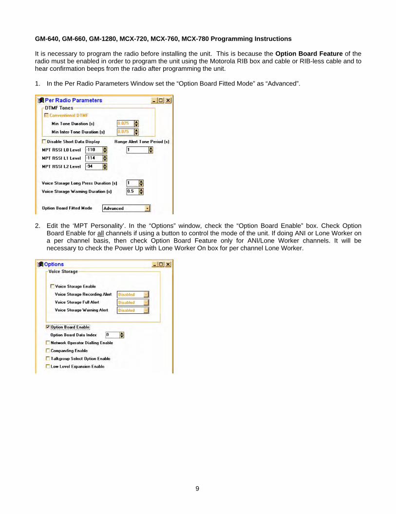
GM-640, GM-660, GM-1280, MCX-720, MCX-760, MCX-780 Programming Instructions It is necessary to program the radio before installing the unit. This is because the Option Board Feature of the radio must be enabled in order to program the unit using the Motorola RIB box and cable or RIB-less cable and to hear confirmation beeps from the radio after programming the unit. 1. In the Per Radio Parameters Window set the “Option Board Fitted Mode” as “Advanced”.
2. Edit the ‘MPT Personality’. In the “Options” window, check the “Option Board Enable” box. Check Option
Board Enable for all channels if using a button to control the mode of the unit. If doing ANI or Lone Worker on a per channel basis, then check Option Board Feature only for ANI/Lone Worker channels. It will be necessary to check the Power Up with Lone Worker On box for per channel Lone Worker.

10
3. If using conventional channels, edit the ‘Conventional Personality Data’. In the “Conventional Personality” window, check the “Option Board Enable” box. Check Option Board Enable for all channels if using a button to control the mode of the unit. If doing ANI or Lone Worker on a per channel basis, then check Option Board Feature only for ANI/Lone Worker channels. It will be necessary to check the Power Up with Lone Worker On box for per channel Lone Worker.

11
HARDWARE INSTALLATION
Be certain to follow standard anti-static procedures when handling any of Midian’s products. Radio Firmware: For the mobile radios listed, it is necessary to have radio firmware version R05.00.00 or higher. If the radio has an older firmware version, it is necessary to upgrade to the newest firmware. Verifying the firmware version can be done several ways. On most radios, this information is on a label on the bottom of the radio. For display radios, selecting the SoftwareVer# option from the utility menu will report the version. Consult Motorola if you cannot determine the firmware version. Disassembling the Radio: Additional disassembly instructions are also available in Motorola’s Basic Service Manual.
1. Disconnect power.
2. Remove plastic cover from the radio chassis by prying the sides away and lifting up.
3. Remove the 6 retaining bolts from the metal lid using a Torx™ size 20 screwdriver. Carefully begin removing the lid. If there is already an option board installed such as a voice storage board, disconnect it by gently lifting the latch holding the 40-pin flex cable in place.
4. Remove the lid completely. Unscrew the three bolts holding the option board frame to the lid if one is
present. Note: It is not recommended to use the radio for transmitting while disassembled, as some model radios require the lid to be installed for RF power. Installing the Unit:
1. Insert the 40-pin flex cable into the 40-pin flex connector on the unit, making certain it is seated properly, then close the latch. The silver foil side of the flex should face the edge of the board.

12
2. The unit is then mounted into the metal lid of the radio using the option board mounting kit. See pictures below. The mounting kit is ordered from Midian as PRO Option B or from Motorola as RLN4823B. The mounting kit includes the 40-pin flex cable, the mounting frame and 3 mounting screws.
Reassembling the Radio: Additional assembly instructions are also available in Motorola’s Basic Service Manual.
1. Once unit is installed in the lid, insert the other side of the 40-pin flex cable into the 40-pin flex connector on the radio’s main board. The shiny side of the flex should face down.
2. Reinstall the metal lid making sure the flex bends toward the back of the radio, otherwise it will be
pinched by the lid. Tighten the screws down in number sequence shown on the lid to 17 in lbs (1.9 NM) torque. Repeat to verify torque is correct after completing the sequence.
3. Snap on plastic cover.

13
PRODUCT PROGRAMMING Install the Midian programming software if you have not done so already. The units are programmed through the radio using the Motorola RIB box and cable or RIBless cable and Midian’s MPS software. Start the Midian programming software. From the product selection screen in the software, locate and select the desired unit model and click OK. Configure the programming software by selecting File->Preferences and make certain there is a check mark next to ‘Rib Box Enable’ by clicking on it. Also select the appropriate COM port. Set the parameters of the software to fit the application. If any clarifications on a feature are required, move the mouse cursor over the feature name until the question mark appears and right click, an on-line help for that feature will be shown. The programming software always defaults to “MDC Portable” as the radio type. On the basic settings tab it is necessary to select the proper radio type. After entering the parameters, save the file by going to File - Save As. Enter the file name in the File Name block and click Save. Saving the file will allow for quick and easy reprogramming of units. Turn power on to the radio and then the RIB. Click ProgramUnit! in the software. You will hear 1-3 beeps from the radio if programmed successfully. To read the parameters from the unit, Click on ReadUnit!. The radio and RIB should be powered down for 3 seconds after reading or programming.
Unit Information This information area is updated when a unit is read or programmed. It will also be updated when a data file is loaded from a previous unit read and then saved. Below is a summary of the fields: Product - Shows a more detailed description of the product model within the series. uP #1 Firmware Version - Indicates the reported Firmware Version of the microcontroller of this product. uP #1 Loader Version - Indicates the reported Loader Version of the microcontroller of this product.

14
Wake on COR/Wake on VOX: Select the appropriate method that the unit should use to come out of power save. COR Hold-Up Time: This is the amount of time after loss of COR/VOX that the unit considers COR/VOX dropped. Sensitivity: This is a threshold detection based on the energy level in the audio. Attack Time: This sets the minimum time before the unit will detect VOX based on the sensitivity setting. Decay Time: This sets the time before the unit will drop the VOX detection. Be certain to set this long enough so that you do not have drop outs between words or on brief pauses. Power Up: Enables a short beep sequence that takes place immediately after power-up. Error: This beep may be triggered by any input event if programmed to do so. For example, if a long press on the Mode Input is not assigned to a function, it may be configured to generate the error beep. Mode: This is used to indicate to the user when the mode has been enabled/disabled (i.e.. Go Ahead: This is a local beep out the speaker to indicate to the user that ANI has been sent and it is okay to talk. Wake Up Beep: Enables a short beep to be sent over the air immediately after PTT is pressed. Enabling this beep is recommended when the 'Wake on VOX' feature is used. Courtesy Beep: If selected, once the unit is done retransmitting the recorded audio it will generate a courtesy tone to let others know it is done retransmitting. Enable Side Tone Pin: Future Use. Voice Compression: If left unchecked the VAE-1 can store up to a 3-minute voice message. If check the VAE-1 can store up to a 2.25 minute voice message, but with a higher level of audio quality.

15
Common PTT: If PTT in and out are connected to the same point, check this box. Trunking Delay Enable: Check this box if using a trunking system. This will cause the unit to hold off transmitting the ANI until it has received a channel acquisition acknowledgement from the radio. Key-Up Delay: This sets the amount of time the unit waits after keying the radio before it transmitting the ANI.
Protocol Format: Select the desired signaling format in which the ANI and ENI will be transmitted. ANI Position: This can be set for the beginning of transmission (leading), end of transmission (trailing) or both. Tone Duration: This field only applies to DTMF and 5-Tone formats and sets the length of each tone. Tone Gap Duration: This field only applies to DTMF and sets the length of the gap between tones. Fleet ID: This field only applies to FleetSync and sets the Fleet ID of the unit. Unit ID: This sets the ANI of the unit. Message: This field only applies to G-Star. Status: This field only applies to G-Star. Repeat Delay: This sets the time after sending an ANI that the unit will wait before sending another ANI.

16
Protocol Format: This displays the format selected on the ANI tab. Unit ID: This sets the Emergency ANI of the unit. Transmit Forever: If selected the ENI will transmit continuously at the repeat interval until canceled. Transmit Count: This sets the number of times the ENI will be sent. Repeat Interval: This sets the time between ENI transmissions. PTT Resets/Cancels ENI: If selected, pressing the PTT button will either reset the Lone Worker’s Transmit Delay time or cancel the transmission of the ENI. Live Mic Enable: If selected the unit will enable the mic of the radio to transmit mic audio to the dispatcher. Revert to Clear: Currently not used. Locator Tone Enable: If selected the unit will emit tones out the radio’s speaker.

17
Transmit Delay: In Lone Worker mode, if the user does not interact with the radio before this amount of time passes, the ENI sequence will be transmitted. This time is in seconds. Warning Tone Enable: This will generate a tone sequence to alert the user the ENI is about to be transmitted. Warning Tone Delay: In Lone Worker mode, if the user does not interact with the radio before this amount of time passes, the emergency warning tone will be sounded. This amount of time must be less than that of the Transmit Delay for the warning tone to be sounded. Also, the Warning Tone Enable box must be checked for the tone to be sounded. For example, based on the screen shown above after 105 seconds of no activity the unit will generate warning tones. The user then has 15 seconds to interact with the radio to keep the Transmit Delay time of 120 seconds expiring and the ENI being transmitted. Continuous Warning Enable: This will generate a constant tone to alert the user the ENI is about to be transmitted. Power-up with Lone Worker on: If checked the unit will be in Lone Worker mode when the radio is turned on. This eliminates the need for the user to use the mode input to turn the Lone Worker mode on. Motion Resets Delay Timers: The unit can then use the accelerometer to detect motion based on the Motion Sensitivity setting to determine if the user is in distress in addition to requiring interaction with the radio. Motion Sensitivity: This sets a level of motion required to reset the Transmit Delay timer. Some work environments may have an inherent level of motion that would be detected by lower settings of the accelerometer, so a higher level of sensitivity might be needed. Midian recommends experimenting to determine the best sensitivity setting for the work environment.

18
Mute GPS or MDC-1200 Packets: If this box is checked, the mute function for Midian GPS or MDC-1200 signaling packets is enabled. Both of these signaling formats begin with a short burst of 1800 Hz tone referred to as preamble tone. When this tone is detected, the receive audio is muted for the duration specified by the 'Mute Duration' setting. Instead of hearing the entire signaling packet, users will only hear a brief 'chirp'.
Transmit Frequency: When the emergency input is grounded the unit sends an Emergency ANI either once or multiple times. This field tells the unit to send the voice alarm with the emergency ANI only on the first Emergency ANI or on all Emergency ANI’s. Require PTT to Record: Most radios will only pass audio to the option board when PTT is pressed. If this is the case this box must be checked. In this mode a button is used to put the unit in record mode and then the PTT is pressed to pass audio to the unit. The unit keeps the audio from being transmitted in record mode, but only if the PTT path is broken. Auto Review: After message recording is completed the unit will replay the message over the speaker to confirm the message. Save Message When Powered Off: This will keep the last recorded message in memory when power is cycled. Auto Record: If checked the unit will start to record immediately upon power up. If the Require PTT to Record box is checked it will wait for the PTT.

19
Tones > Beep Volume: Adjust the slider for the desired beep volume. This level is expressed as a percentage of max voice audio level. Tones > Over-The-Air-Signal Modulation: Adjust the slider for the desired beep volume. This level is expressed as a percentage of max voice audio level. For these radios Midian recommends using 78%.
Playback > Playback Level: This controls the audio level when a stored voice message is played back on the radio speaker. If voice playback is too low or too loud, adjust this level accordingly. Playback > Transmit Level: This controls the audio level when a stored voice message is retransmitted over the air. If the transmit level is too low or too loud, adjust this level accordingly. See Page 22 for the Voice Audio Level Settings
20
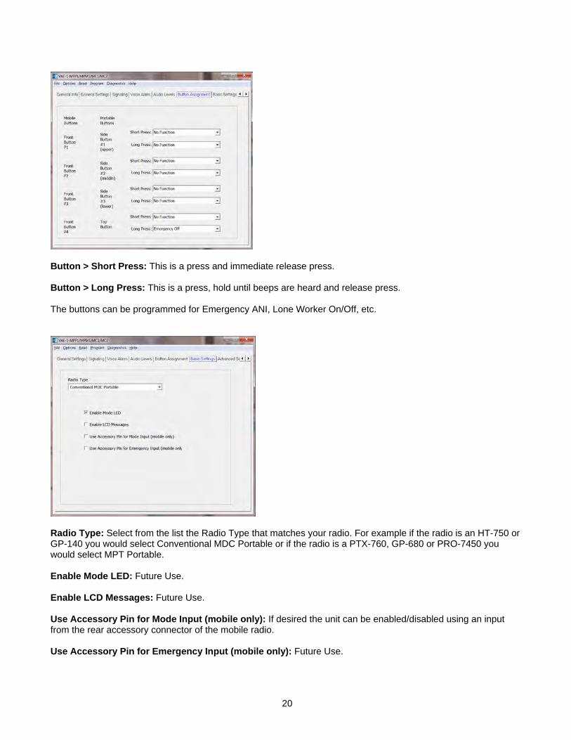
Button > Short Press: This is a press and immediate release press. Button > Long Press: This is a press, hold until beeps are heard and release press. The buttons can be programmed for Emergency ANI, Lone Worker On/Off, etc.
Radio Type: Select from the list the Radio Type that matches your radio. For example if the radio is an HT-750 or GP-140 you would select Conventional MDC Portable or if the radio is a PTX-760, GP-680 or PRO-7450 you would select MPT Portable. Enable Mode LED: Future Use. Enable LCD Messages: Future Use. Use Accessory Pin for Mode Input (mobile only): If desired the unit can be enabled/disabled using an input from the rear accessory connector of the mobile radio. Use Accessory Pin for Emergency Input (mobile only): Future Use.

21
The “Option Board Always Controls PTT” box must be checked. Otherwise please only adjust the parameters of this screen when advised to by Midian.
22
AUDIO LEVELS ALIGNMENT
This section describes how to determine and set the audio levels. Audio Levels Overview: To ensure the best audio quality, the unit must be configured to match the audio levels used by the radio. The unit uses programmable gain amplifiers to accomplish this. Determining the gain settings for these amplifiers is an involved process, so Midian simplified this process by developing an algorithm that requires the technician to make only four voltage measurements. From these four measurements, all of the many internal settings are determined. Still, getting the best audio quality will likely require a bit of trial and error. The unit only has control of audio voltage levels, not input and output impedances. These impedances can dramatically influence the levels. The Four Voltage Measurements: An oscilloscope and a communications test set/service monitor are required for the measurements. It is recommended that the measurements be recorded in units of mV peak-to-peak. Each measurement must be taken with system modulation at either 60% or 100%, but Midian recommends using 60% These measurements must be taken within 15 seconds of powering the unit on. This is because the unit will enter power saving mode after that time. Measurements made while the unit is in power saving mode will not be valid. TX Alignment Set-Up: A method for controlling transmit modulation is required for accurate measurements in the TX mode. A small speaker held in place near the microphone by a rubber band can serve this purpose in most cases. Use a sine-wave generator to inject a 1000 Hz tone into the speaker. Adjust the output of the sine wave generator so that the transmitter produces 60% of rated modulation while PTT is pressed. Note that if the audio source (such as a speaker) is moved even slightly, the TX modulation may change significantly. Care must be taken to avoid changing the TX modulation while taking the measurements. RX Alignment Set-Up: Using a service monitor send a fully quieting signal (-50 dBm) to the receiver with a 1000 Hz tone at 60% modulation, adjust the volume of the receiver to a comfortable listening level and measure the audio level at the speaker using an AC coupled oscilloscope. Once the volume is adjusted and the measurement taken do not adjust the volume control during the remainder of the alignment. 1. TX Input: The goal of this procedure is to determine the audio level that the unit board will see at the TX
audio pickup point after it is installed. The unit must be installed and powered-on while making this measurement. Use the TX Alignment Set-Up procedure and measure the audio level at TP1 on the unit.
2. RX Input: The goal of this procedure is to determine the audio level that the unit board will see at the RX audio pickup point after it is installed. The unit must be installed and powered-on while making this measurement. Use the TX Alignment Set-Up procedure and measure the audio level at TP2 on the unit.
3. In the programming software under audio levels set the TX In to the same level as measured in step 1 and for a preliminary adjustment set the TX Out for the same level. Set the RX In to the same level as measured in step 2 and for a preliminary adjustment set the RX Out for the same level. Program the unit.
4. RX Output: The goal of this procedure is to determine the audio level that would normally appear at the RX audio insertion point in an unmodified radio. Using the same RX Alignment Set-Up procedure verify the audio level at the speaker is still at the same level measured initially in the RX Alignment Set-Up procedure. If not adjust the RX Out level accordingly.
5. TX Output: The goal of this procedure is to determine the audio level that would normally appear at the TX audio insertion point in an unmodified radio. Using the same TX Alignment Set-Up procedure verify the modulation is still at 60%, if not adjust the TX Out level accordingly.

23
Programming the Audio Levels: After determining the audio levels at the audio hookup points, it will be necessary to program the unit to match these levels. In the programming software, there is a slider control on the Audio Levels Screen for each of the of four audio hookup points. Locate the column that corresponds to the modulation and units of measurement for each of the audio hookup points. Adjust the slider bar such that the value appearing in the appropriate column matches what was measured as closely as possible. Radio Model RX In TX In RX Out TX Out CDM-750, CDM-1250, GM-140, GM-160, GM-328, GM-338, GM-398, PRO-3100, PRO-5100, PRO-7100
888 210 186 210
GM-340, GM-360, GM-380, GM-339, GM-399, PRO-7200 1044 228 240 216 GM-338-LS, CDM-1550-LS+ 888 270 186 252 GM-640, GM-660, GM-1280, MCX-720, MCX-760, MCX-780
24
OPERATION
ANI Encode: When the PTT button is pressed, the unit will assert the PTT Output and send the programmed ANI tones out the TX Tone Output. ENI Encode: When the Emergency input is activated, the unit will assert the PTT Output and send the programmed Emergency ANI tones out the TX Tone Output. Lone Worker Enable: The Lone Worker feature can be enabled upon power up or using the Mode Input or Emergency Input. Lone Worker Reset: If the Lone Worker feature is being used, pressing the PTT or pressing the button assigned to Lone Worker Reset will reset the Transmit Delay timer. If the Warning Tone Delay time expires the unit will generate warning tones to indicate to the user that the Lone Worker feature is about to send an ENI if the unit does not see PTT or Lone Worker Reset activity. If the Transmit Delay time then expires the unit will send the ENI. Message Recording on Power Up: If the Auto Record feature is enabled the unit will record a voice message immediately upon power up. If the radio requires PTT to pass voice to the option board and the Require PTT to Record box is checked, the unit will wait to record until the PTT is pressed. Message Recording with Mode Button: Using the button(s) set for controlling record start and stop, press the button in the manner programmed in Mode Input to start recording. If the radio requires PTT to pass voice to the option board and the Require PTT to Record box is checked, the unit will wait to record until the PTT is pressed. When recording is completed, press the button in the manner programmed in Mode Input to stop recording. When the recording is stopped the unit will play back the recorded message if the Auto Review box is checked.
TECHNICAL NOTES
Radio Compatibility: Midian has taken the utmost care to ensure the option board integrates into the radio with minimal impact to the features of the radio. However, some features may not be available in the radio when an option board is used. If a feature is not available, please contact Midian to see if the feature can be added. Radio Firmware: Midian recommends installing the module into the radio with the existing firmware of the radio provided the firmware is at least R05.00.00. If the radio has a firmware version older than R05.00.00, it must be upgraded. If there are any issues with the firmware then the firmware should be upgraded to the latest. However, it should be noted that occasionally firmware updates may cause a conflict with proper option board/radio communications. This may appear that the unit is not working properly, but it is a conflict in the serial communication between the option board and radio. Please note that firmware versions between the EMEA region and the Asia and America regions might be different. Accessory Pin Features: Upon power-up, the radio does not always report the state of the accessory pins to the option board. It may be necessary to toggle the state of these inputs once after power-up to ensure correct operation. Option Board Feature: Enabling the option board feature tells the radio to report events such as button press, PTT press, carrier detect, etc. to the option board. This feature enables communication between the option board and the radio. On display models, the following icon appears on the LCD when option board mode is on:
Known Issues: The radio must be off for a full 3 seconds prior to being turned on or the unit cannot reset properly resulting in malfunction. The "Enable LCD Message" option in the KL-3 software should not be enabled due to problems in the radio. If problems are experienced when reading the unit from the RIB box, use the KL-3 cable.

25
MIDIAN CONTACT INFORMATION
MIDIAN ELECTRONICS, INC. 2302 East 22nd Street Tucson, Arizona 85713 USA Toll-Free: 1-800-MIDIANS Main: 520-884-7981 E-mail: [email protected] Web: HUwww.midians.comU

1
1
2
2
3
3
4
4
5
5
6
6
D D
C C
B B
A A
47KR2
+3.3V
560pC1
+3.3V
560pC2
47KR7
47KR6
560pC4
100KR15
100KR14
+3.3VDD.1uC7
2RR49
2RR50
2RR51
+3.3V
+3.3VA
+3.3VDD
8.2KR16
27KR13
.1uC10
.01uC9
4.7KR8
+3.3V
VAN
.0068uC15
.0068uC16 56K
R18
36KR21
.001uC18
75KR19
VAN
1.2MR20
VAN
10KR9.1u
C12
VAN
100pC14
10K1%R11
10K1%R12
10KR10
39pC44
+3.3V+3.3V
.1uC25
.01uC21
560pC19VAN
TP8
TP18
TP7
TP6
TP17
TP5
TP12
TP3
TP4
TP1
TP2
.01uC45
P4:1
P4:2
P4:3
P4:4
P4:5
P4:6
.1uC28
.1uC29
.1uC30
.1uC31
10uC36
10uC35
10uC32
12pC38
100pC39
32 KHzY1
+3.3V
+3.3V
+3.3VDD
+3.3VA
+3.3V
VDDD
4.7KR30
+3.3V
47KR31
+3.3V
VDDD
VDDD
100KR34
100KR35
560pC37
.1uC41
10uC40+3.3V
SW_B+
SRD_SND
SCK_SND
100pC617
VDDD
0RR32
PTT_IN_OUT
4001Q1
4001Q2
*Q6
0RR52
SB1D1
SB1D2
SB1D4
SB1D3
560pC11
0RR57
0RCR58
47KR36 +3.3V
+3.3V .1uC43
SB1D6
.1uC42
RESET
CP
CJS2009-03-25 AWS
2014-26-08
F-1
1 of 2 7701SCHEMATIC
Copyright © 2014
MIDIAN ELECTRONICS, INC.DATE:DESIGN:
UPD BY:REV:
APPR
REV
SHEET PROJECT NUMBER
DOCUMENT NAMEVS SERIES PRO
2.2uC13
SERIES VR2 VR3 U3 U6 U10VS-1200/110/1100 Y Y Y * *
VS-1000VS-1050
SVR-1/VM-3TS-120VAE-1
* * * * ** * * * Y* * * Y ** * * * Y* * * Y Y
* = NOT INSTALLEDY = INSTALLED
R570R0R0R0R0R225
R580R0R0R0R0R
*****
*R1
IN11
ENA3
GN
D2
RES
4
OUT 5
MIC5206 3.3V
VR1
IN11
ENA3
GN
D2
RES
4
OUT 5
MIC5206
VR2
IN11
ENA3
GN
D2
RES
4
OUT 5
MIC5206
VR3
.01uC47
.22uC33
0RL1
2.2uC27
2.2uC26
22pC24
3.3KR24
*R17
2.2uC20
*C52
-
+
2
31
411
LMV324U7:1-
+
6
57
LMV324U7:2
-
+
9
108
LMV324
U7:3
-
+
13
1214
LMV324U7:4
3
1
2
4
5 6
U5
7 482 5
16 3
U4
16
13
42
11
9
4
3
37
8
47
28
24
27
20
18
36
43
46
48
45
416
44
1 2 3840 39
34
21
227
35
17
19
29
25
2326
12
10
5
15
14
33323031
49
U1
CS1
SO2
SI5
SCK6
VCC 8
HOLD 7
WP 3
GND 4
AT26DF081AU6
CS7
SO12
SI13
SCK14
DVDD 1
INT29 INT18
GND 2
AVDD 6
GND 5
IADDR0 431011
MMA7455LU10
16
15
33
35
36
37
38
3
11
12
20
46
21
2
39
40
41
42
32 31 13 10 45 1743
30
29
26
27
28
5 14 34 44
1
4
67
8
9
18
19
22
23
24
25
47
48
U3
*C17
*C48
*C51
4.7KR54
4.7KR55
RDY
MISO
TX OUT
RX OUT
EXT MIC
OPT ENA
TX IN
RX IN
DIS IN
PTT_IN_OUT
VDDD
SW_B+
GND
-
+
33
114
52
LM321U12
1KR87
+3.3VA
.01uC85
47pC84
36KR88
120KR89
22KR28
130K1%R3
130K1%R4
.0068uC3
.0068uC6
27KR5
10KR23
10KR22
FLAT TX OUT
VDDD
22pC8
P3
:1
P3:2
P3:3
P3:4
P3:5
TABLE 1R3
CJS CT-1 * * * * *
******
R5 R29*******
Y* 0R
*R29
Y
1
2PROG IN
PROG OUT
P2
225*
+
10uC5
U12Y******
PIC101
PIC102COC1
PIC201
PIC202COC2
PIC301
PIC302COC3
PIC401
PIC402COC4
PIC501
PIC502COC5
PIC601
PIC602COC6
PIC701
PIC702COC7
PIC801
PIC802COC8
PIC901 PIC902
COC9
PIC1001
PIC1002COC10
PIC1101 PIC1102
COC11
PIC1201 PIC1202
COC12
PIC1301
PIC1302COC13
PIC1401
PIC1402COC14
PIC1501 PIC1502
COC15
PIC1601 PIC1602
COC16
PIC1701 PIC1702
COC17
PIC1801PIC1802
COC18
PIC1901
PIC1902COC19 PIC2001
PIC2002COC20
PIC2101 PIC2102
COC21
PIC2401
PIC2402COC24
PIC2501 PIC2502
COC25
PIC2601
PIC2602COC26PIC2701
PIC2702COC27
PIC2801 PIC2802
COC28
PIC2901 PIC2902
COC29
PIC3001 PIC3002
COC30
PIC3101
PIC3102COC31 PIC3201
PIC3202COC32
PIC3301 PIC3302
COC33
PIC3501 PIC3502
COC35
PIC3601 PIC3602
COC36
PIC3701
PIC3702COC37
PIC3801
PIC3802COC38
PIC3901
PIC3902COC39
PIC4001 PIC4002
COC40
PIC4101 PIC4102
COC41
PIC4201 PIC4202
COC42
PIC4301 PIC4302
COC43
PIC4401
PIC4402COC44
PIC4501
PIC4502COC45
PIC4701 PIC4702
COC47
PIC4801 PIC4802
COC48
PIC5101
PIC5102COC51 PIC5201
PIC5202COC52
PIC8401
PIC8402COC84
PIC8501
PIC8502COC85
PIC61701
PIC61702COC617
PICR5801 PICR5802
COCR58
PID101PID102
COD1
PID201PID202
COD2
PID301PID302
COD3
PID401PID402
COD4
PID601PID602
COD6
PIL101
PIL102
COL1
PIP201
PIP202
COP2
PIP301
COP3:1PIP302
COP3:2PIP303
COP3:3PIP304
COP3:4PIP305
COP3:5
PIP401 COP4:1
PIP402 COP4:2
PIP403 COP4:3
PIP404 COP4:4
PIP405 COP4:5
PIP406 COP4:6
PIQ10DPIQ10G
PIQ10S
COQ1
PIQ20DPIQ20G
PIQ20S
COQ2
PIQ60DPIQ60G
PIQ60S
COQ6
PIR101 PIR102
COR1
PIR201 PIR202
COR2
PIR301 PIR302
COR3
PIR401 PIR402
COR4
PIR501 PIR502
COR5
PIR601 PIR602
COR6
PIR701 PIR702
COR7
PIR801 PIR802
COR8
PIR901 PIR902
COR9 PIR1001 PIR1002
COR10
PIR1101 PIR1102
COR11 PIR1201 PIR1202
COR12
PIR1301
PIR1302
COR13
PIR1401
PIR1402
COR14
PIR1501
PIR1502
COR15 PIR1601
PIR1602
COR16
PIR1701 PIR1702
COR17
PIR1801 PIR1802
COR18PIR1901 PIR1902
COR19
PIR2001 PIR2002
COR20
PIR2101 PIR2102
COR21
PIR2201
PIR2202
COR22
PIR2301
PIR2302
COR23PIR2401 PIR2402
COR24
PIR2801 PIR2802
COR28
PIR2901 PIR2902
COR29
PIR3001
PIR3002
COR30
PIR3101
PIR3102
COR31
PIR3201 PIR3202
COR32
PIR3401 PIR3402
COR34
PIR3501 PIR3502
COR35
PIR3601 PIR3602
COR36
PIR4901 PIR4902
COR49
PIR5001 PIR5002
COR50
PIR5101 PIR5102
COR51
PIR5201 PIR5202
COR52
PIR5401 PIR5402
COR54
PIR5501 PIR5502
COR55
PIR5701 PIR5702
COR57
PIR8701
PIR8702
COR87PIR8801 PIR8802
COR88
PIR8901 PIR8902
COR89
COtb0sch1
PITP101
COTP1
PITP201
COTP2
PITP301
COTP3
PITP401
COTP4
PITP501
COTP5
PITP601
COTP6
PITP701
COTP7
PITP801
COTP8
PITP1201
COTP12
PITP1701
COTP17
PITP1801
COTP18
COTxt1
PIU101 PIU102
PIU103
PIU104
PIU105
PIU106
PIU107
PIU108
PIU109
PIU1010
PIU1011
PIU1012
PIU1013
PIU1014
PIU1015
PIU1016
PIU1017
PIU1018
PIU1019
PIU1020
PIU1021
PIU1022
PIU1023
PIU1024
PIU1025
PIU1026
PIU1027
PIU1028
PIU1029
PIU1030
PIU1031
PIU1032
PIU1033
PIU1034
PIU1035
PIU1036
PIU1037
PIU1038PIU1039PIU1040
PIU1041
PIU1042
PIU1043
PIU1044
PIU1045
PIU1046
PIU1047
PIU1048
PIU1049
COU1
PIU301
PIU302
PIU303
PIU304
PIU305
PIU306
PIU307
PIU308
PIU309
PIU3010
PIU3011
PIU3012
PIU3013
PIU3014
PIU3015
PIU3016
PIU3017PIU3018
PIU3019
PIU3020
PIU3021
PIU3022
PIU3023
PIU3024
PIU3025
PIU3026
PIU3027
PIU3028
PIU3029
PIU3030
PIU3031PIU3032
PIU3033 PIU3034
PIU3035
PIU3036
PIU3037
PIU3038
PIU3039
PIU3040
PIU3041
PIU3042
PIU3043
PIU3044
PIU3045
PIU3046
PIU3047
PIU3048
COU3
PIU401
PIU402
PIU403
PIU404
PIU405
PIU406
PIU407PIU408
COU4
PIU501
PIU502
PIU503
PIU504
PIU505 PIU506
COU5
PIU601
PIU602
PIU603
PIU604
PIU605
PIU606
PIU607
PIU608
COU6
PIU701
PIU702
PIU703PIU704
PIU7011COU7:1
PIU705
PIU706
PIU707COU7:2
PIU708
PIU709
PIU7010
COU7:3
PIU7012
PIU7013
PIU7014COU7:4
PIU1001
PIU1002
PIU1003
PIU1004
PIU1005
PIU1006
PIU1007
PIU1008
PIU1009
PIU10010
PIU10011
PIU10012
PIU10013
PIU10014
COU10
PIU1201
PIU1202
PIU1203
PIU1204
PIU1205COU12
PIVR101
PIVR102
PIVR103
PIVR104
PIVR105
COVR1
PIVR201
PIVR202
PIVR203
PIVR204
PIVR205
COVR2
PIVR301
PIVR302
PIVR303
PIVR304
PIVR305
COVR3
PIY101
PIY102COY1

PAC101PAC102COC1
PAC201PAC202COC2
PAC302PAC301COC3
PAC401PAC402COC4
PAC501
PAC502COC5
PAC602
PAC601
COC6
PAC701
PAC702
COC7
PAC802
PAC801
COC8
PAC901
PAC902
COC9
PAC1001PAC1002COC10
PAC1101 PAC1102COC11
PAC1201
PAC1202COC12
PAC1301 PAC1302COC13
PAC1401
PAC1402COC14
PAC1501
PAC1502
COC15PAC1601
PAC1602
COC16 PAC1701PAC1702COC17
PAC1801PAC1802COC18
PAC1901PAC1902COC19
PAC2001PAC2002COC20
PAC2101 PAC2102COC21
PAC2401
PAC2402COC24
PAC2501 PAC2502COC25
PAC2601 PAC2602COC26
PAC2701 PAC2702COC27
PAC2801PAC2802COC28
PAC2901PAC2902COC29
PAC3001PAC3002COC30
PAC3101
PAC3102
COC31 PAC3201
PAC3202
COC32
PAC3301
PAC3302COC33PAC3501
PAC3502COC35PAC3601
PAC3602COC36
PAC3701
PAC3702COC37
PAC3801
PAC3802
COC38PAC3901
PAC3902
COC39
PAC4001 PAC4002COC40
PAC4101PAC4102COC41
PAC4201 PAC4202COC42
PAC4301
PAC4302COC43
PAC4401PAC4402COC44
PAC4501
PAC4502
COC45
PAC4701
PAC4702
COC47
PAC4801PAC4802COC48
PAC5101
PAC5102COC51
PAC5201
PAC5202COC52
PAC8402
PAC8401
COC84PAC8502
PAC8501COC85
PAC60901
PAC60902COC609 PAC61001
PAC61002COC610
PAC61101
PAC61102COC611PAC61201
PAC61202
COC612
PAC61301PAC61302COC613
PAC61501
PAC61502
COC615PAC61601PAC61602COC616
PAC61701
PAC61702COC617
PACR5801 PACR5802COCR58
PAD101
PAD102
COD1
PAD201 PAD202COD2
PAD301
PAD302
COD3
PAD401 PAD402COD4
PAD601PAD602 COD6
PAJ601013
PAJ60106
PAJ601019
PAJ60101PAJ60102
PAJ60103PAJ60104
PAJ60105
PAJ60107PAJ60108
PAJ60109PAJ601010
PAJ601011PAJ601012
PAJ601014PAJ601015
PAJ601016PAJ601017
PAJ601018
PAJ601020PAJ601021
PAJ601022PAJ601023
PAJ601024PAJ601025
PAJ601026PAJ601027
PAJ601028PAJ601029
PAJ601030PAJ601031
PAJ601032PAJ601033
PAJ601034PAJ601035
PAJ601036PAJ601037
PAJ601038PAJ601039
PAJ601040
PAJ6010APAJ6010B
PAJ6010CPAJ6010DCOJ601
PAJ602018
PAJ602017
PAJ602016
PAJ602015
PAJ602014
PAJ602013
PAJ602012
PAJ602011
PAJ602010
PAJ60209
PAJ60208
PAJ60207
PAJ60206
PAJ60205
PAJ60204
PAJ60203
PAJ60202
PAJ60201
PAJ6020B
PAJ6020A
COJ602
PAL101
PAL102
COL1
PAP201PAP202 COP2 PAP304 PAP303PAP305 PAP302 PAP301COP3
PAP404PAP406 PAP403PAP405 PAP402 PAP401COP4
PAQ10SPAQ10D
PAQ10GCOQ1
PAQ20SPAQ20D
PAQ20G
COQ2
PAQ60SPAQ60D
PAQ60GCOQ6
PAQ6010BPAQ6010C
PAQ6010ECOQ601
PAQ6020BPAQ6020C
PAQ6020ECOQ602
PAQ6030BPAQ6030C
PAQ6030ECOQ603
PAR101
PAR102
COR1
PAR201
PAR202COR2
PAR302
PAR301COR3
PAR402PAR401COR4
PAR502PAR501COR5
PAR601
PAR602COR6
PAR701
PAR702COR7
PAR801 PAR802COR8
PAR901
PAR902COR9
PAR1001
PAR1002COR10PAR1101PAR1102COR11
PAR1201 PAR1202COR12
PAR1301
PAR1302
COR13
PAR1401 PAR1402COR14
PAR1501
PAR1502COR15
PAR1601
PAR1602
COR16
PAR1701 PAR1702COR17
PAR1801PAR1802COR18
PAR1901 PAR1902COR19 PAR2001
PAR2002
COR20PAR2101 PAR2102COR21 PAR2202
PAR2201COR22PAR2302PAR2301COR23
PAR2401PAR2402COR24
PAR2802
PAR2801
COR28
PAR2902PAR2901COR29
PAR3001
PAR3002
COR30 PAR3101 PAR3102COR31
PAR3201PAR3202COR32
PAR3401
PAR3402COR34
PAR3501
PAR3502COR35
PAR3601 PAR3602COR36
PAR4901
PAR4902
COR49
PAR5001PAR5002COR50
PAR5101
PAR5102
COR51
PAR5201PAR5202COR52
PAR5401PAR5402COR54
PAR5501PAR5502COR55
PAR5701 PAR5702COR57
PAR8702 PAR8701COR87
PAR8802
PAR8801COR88PAR8902
PAR8901
COR89
PAR60101 PAR60102COR601
PAR60201
PAR60202
COR602PAR60301 PAR60302COR603
PAR60401PAR60402COR604
PAR60501 PAR60502COR605
PAR60601PAR60602COR606
PAR60701 PAR60702COR607
PAR60801PAR60802COR608
PAR60901 PAR60902COR609
PAR61001PAR61002COR610
PAR61101PAR61102COR611
PAR61201
PAR61202COR612PAR61301
PAR61302COR613
PAR61801
PAR61802COR618
PAR61901 PAR61902COR619
PAR62001PAR62002COR620
PAR62101PAR62102COR621
PAR62201 PAR62202COR622
PAR62301
PAR62302COR623
PAR62501 PAR62502COR625
PAR62901
PAR62902COR629
PAR63001
PAR63002COR630
PAR63101PAR63102COR631
PAR63201
PAR63202
COR632
PAR63301PAR63302COR633
PAR63801PAR63802COR638
PAR64601PAR64602COR646
PAR64701PAR64702COR647
PAR64801PAR64802COR648
PAR64901PAR64902COR649
COtb0sch1
PATP101 COTP1
PATP201 COTP2
PATP301COTP3
PATP401COTP4
PATP501COTP5
PATP601COTP6
PATP701
COTP7
PATP801 COTP8
PATP1201
COTP12
PATP1701COTP17
PATP1801
COTP18
PAU101PAU102
PAU103PAU104
PAU105PAU106
PAU107PAU108
PAU109PAU1010PAU1011
PAU1012
PAU1013PAU1014
PAU1015PAU1016
PAU1017PAU1018
PAU1019PAU1020
PAU1021PAU1022PAU1023
PAU1024 PAU1025PAU1026
PAU1027PAU1028
PAU1029PAU1030
PAU1031PAU1032
PAU1033PAU1034
PAU1035PAU1036
PAU1037PAU1038
PAU1039PAU1040PAU1041
PAU1042PAU1043
PAU1044PAU1045
PAU1046PAU1047
PAU1048
PAU1049COU1
PAU3048PAU3047PAU3046PAU3045PAU3044PAU3043PAU3042PAU3041PAU3040PAU3039PAU3038PAU3037PAU3036
PAU3035
PAU3034
PAU3033
PAU3032
PAU3031
PAU3030
PAU3029
PAU3028
PAU3027
PAU3026
PAU3025
PAU3024 PAU3023 PAU3022 PAU3021 PAU3020 PAU3019 PAU3018 PAU3017 PAU3016 PAU3015 PAU3014 PAU3013PAU3012
PAU3011
PAU3010
PAU309
PAU308
PAU307
PAU306
PAU305
PAU304
PAU303
PAU302
PAU301
COU3
PAU401
PAU402
PAU403
PAU404 PAU405
PAU406
PAU407
PAU408
COU4 PAU506
PAU505
PAU504PAU503
PAU502
PAU501
COU5
PAU601
PAU602
PAU603
PAU604 PAU605
PAU606
PAU607
PAU608
COU6
PAU7014
PAU7013
PAU7012
PAU7011
PAU7010
PAU709
PAU708PAU707
PAU706
PAU705
PAU704
PAU703
PAU702
PAU701
COU7
PAU10014PAU10013PAU10012PAU10011PAU10010PAU1009PAU1008 PAU1007 PAU1006
PAU1005PAU1004PAU1003PAU1002PAU1001
COU10PAU1204
PAU1203 PAU1202
PAU1205
PAU1201
COU12
PAU60203
PAU60201
PAU60204
PAU60202
PAU60205COU602
PAVO102 PAVO101
PAVO10E
PAVO10CPAVO10B
PAVO103
PAVO104
PAVO105
PAVO106
PAVO107
PAVO108
PAVO109
PAVO1010
PAVO1011
PAVO1012
PAVO1013PAVO1014PAVO1015PAVO1016PAVO1017PAVO1018PAVO1019PAVO1020PAVO1021PAVO1022PAVO1023PAVO1024PAVO1025
PAVO1026
PAVO1027
PAVO1028
PAVO1029
PAVO1030
PAVO1031
PAVO1032
PAVO1033
PAVO1034
PAVO1035
PAVO1036
PAVO1037 PAVO1038 PAVO1039 PAVO1040 PAVO1041 PAVO1042 PAVO1043 PAVO1044 PAVO1045 PAVO1046 PAVO1047 PAVO1048
PAVO10A
PAVO1049
PAVO10GPAVO10D
PAVO10S
COVO1
PAVR103
PAVR101
PAVR104
PAVR102
PAVR105
COVR1
PAVR203 PAVR201
PAVR204
PAVR202
PAVR205COVR2
PAVR303PAVR301
PAVR304
PAVR302
PAVR305
COVR3
PAY101PAY102COY1