vacuum tube pinouts
TRANSCRIPT

Tube Pg Tube Pg Tube Pg Tube Pg Tube Pg Tube Pg Tube Pg
5AQ5 12 6AQ5 12 6FQ7 33 12AQ5 12 50BM8 29 7025 23 ECC81 23
5AR4 5 6AQ5A 12 6FV8A 30 12AT7 23 50L6 10 7027A 19 ECC82 23
5AU4 6 6AQ5W 12 6GW8 35 12AU6 11 5751 23 7189 26 ECC83 23
5BR8 30 6AU6 11 6HG5 12 12AU7 23 5881 10 7189A 26 ECC832 23
5BS8 24 6BM8 29 6HR5 12 12AX7 23 7199 32 ECC88 24
5FV8 30 6BQ5 26 6J7 14 12AY7 23 6005 12 7591A 20 ECL82 29
5U4 6 6BR8A 30 6K11 39 12BH7 23 6072A 23 76 3 ECL86 35
5V3 6 6C4 8 6L6 10 12BV7 25 6095 12 7868 37 EL34 18
5Y3 6 6C6 9 6N7 16 12BY7A 25 60FX5 13 EL84 26
5Z3 2 6C10 38 6Q11 39 12DQ7 25 6201 23 EZ80 36
6CA4 36 6SC7 22 12DW7 23 6550 15 EZ81 36
6CA7 18 6SJ7 21 12FX5 13 6669 12 GZ34 5
6CG7 33 6SL7 17 12SL7 17 6679 23 KT66 10
6CX8 27 6SN7 17 12SN7 17 6680 23 KT88 18
6CZ5 31 6V4 36 18GD6A 11 6681 23 UCL82 29
6DJ8 24 6V6 10 35Z5 7 6922 24
6EU7 34 36AM3 4 6973 28
BustedGear.com
PAGE 1
VACUUM TUBE PINOUT SHEETSINDEX

PIN DIAGRAM: 4C INDEX
AMPLIFIER MAKE:
MODEL:
SERIAL NO:
a: b: c: d: e: f:
1 Filament
2 d2 - Plate
3 d1 - Plate
4 Filament
PAGE 2 BustedGear.com
5Z3
SUBSCRIPTS FOR MULTI-UNIT TUBES: b = Beam Power Unit. d = Diode Unit. hp = Heptode Unit. hx = Hexode Unit. p = Pentode Unit. t = Triode Unit. tr = Tetrode Unit. 1, 2, 3, etc. = No. 1, No. 2, No. 3, etc
VOLTAGE READINGS
FULL-WAVE RECTIFIER
TERMINAL ABBREVIATIONS: H = Heater End (Unpolarized). HM = Heater Tap. IC = Do Not Use (Internal Connection). IS = Internal Shield (Electrostatic). K = Cathode. NC = No Internal Connection. S = Metal Shell.
WIRING SIDE OF SOCKET IS SHOWN
ELECTRODEPIN

PIN DIAGRAM: 5A INDEX
AMPLIFIER MAKE:
MODEL:
SERIAL NO:
a: b: c: d: e: f:
1 Heater
2 Plate
3 Grid
4 Cathode
5 Heater
PAGE 3 BustedGear.com
76
SUBSCRIPTS FOR MULTI-UNIT TUBES: b = Beam Power Unit. d = Diode Unit. hp = Heptode Unit. hx = Hexode Unit. p = Pentode Unit. t = Triode Unit. tr = Tetrode Unit. 1, 2, 3, etc. = No. 1, No. 2, No. 3, etc
VOLTAGE READINGS
MEDIUM-MU TRIODE
TERMINAL ABBREVIATIONS: H = Heater End (Unpolarized). HM = Heater Tap. IC = Do Not Use (Internal Connection). IS = Internal Shield (Electrostatic). K = Cathode. NC = No Internal Connection. S = Metal Shell.
WIRING SIDE OF SOCKET IS SHOWN
PIN ELECTRODE

PIN DIAGRAM: 5BQ INDEX
AMPLIFIER MAKE:
MODEL:
HALF-WAVE RECTIFIER SERIAL NO:
a: b: c: d: e: f:
1 NC
2 NC
3 Heater
4 Heater
5 Plate
6 Heater Tap
7 Cathode
PAGE 4 BustedGear.com
36AM3
SUBSCRIPTS FOR MULTI-UNIT TUBES: b = Beam Power Unit. d = Diode Unit. hp = Heptode Unit. hx = Hexode Unit. p = Pentode Unit. t = Triode Unit. tr = Tetrode Unit. 1, 2, 3, etc. = No. 1, No. 2, No. 3, etc
VOLTAGE READINGS
TERMINAL ABBREVIATIONS: H = Heater End (Unpolarized). HM = Heater Tap. IC = Do Not Use (Internal Connection). IS = Internal Shield (Electrostatic). K = Cathode. NC = No Internal Connection. S = Metal Shell.
WIRING SIDE OF SOCKET IS SHOWN
PIN ELECTRODE

PIN DIAGRAM: 5DA INDEX
AMPLIFIER MAKE:
MODEL:
SERIAL NO:
a: b: c: d: e: f:
1 IC
2 Heater
4 d2 - Plate
6 d1 - Plate
8 Heater, Cathode
PAGE 5 BustedGear.com
5AR4 / GZ34
SUBSCRIPTS FOR MULTI-UNIT TUBES: b = Beam Power Unit. d = Diode Unit. hp = Heptode Unit. hx = Hexode Unit. p = Pentode Unit. t = Triode Unit. tr = Tetrode Unit. 1, 2, 3, etc. = No. 1, No. 2, No. 3, etc
VOLTAGE READINGS
FULL-WAVE RECTIFIER
TERMINAL ABBREVIATIONS: H = Heater End (Unpolarized). HM = Heater Tap. IC = Do Not Use (Internal Connection). IS = Internal Shield (Electrostatic). K = Cathode. NC = No Internal Connection. S = Metal Shell.
WIRING SIDE OF SOCKET IS SHOWN
PIN ELECTRODE

PIN DIAGRAM: 5T INDEX
AMPLIFIER MAKE:
MODEL:
SERIAL NO:
a: b: c: d: e: f:
1 NC
2 Filament
NC or OMITTED
4 d2 - Plate
NC or OMITTED
6 d1 - Plate
NC or OMITTED
8 Filament
PAGE 6 BustedGear.com
5Y3GT
SUBSCRIPTS FOR MULTI-UNIT TUBES: b = Beam Power Unit. d = Diode Unit. hp = Heptode Unit. hx = Hexode Unit. p = Pentode Unit. t = Triode Unit. tr = Tetrode Unit. 1, 2, 3, etc. = No. 1, No. 2, No. 3, etc
5V3A/5AU45U4GB
VOLTAGE READINGS
FULL-WAVE RECTIFIER
TERMINAL ABBREVIATIONS: H = Heater End (Unpolarized). HM = Heater Tap. IC = Do Not Use (Internal Connection). IS = Internal Shield (Electrostatic). K = Cathode. NC = No Internal Connection. S = Metal Shell.
WIRING SIDE OF SOCKET IS SHOWN
PIN ELECTRODE

PIN DIAGRAM: 6AD INDEX
AMPLIFIER MAKE:
MODEL:
SERIAL NO:
a: b: c: d: e: f:
1 NC or OMITTED
2 Heater
3 Heater Tap - Panel Lamp
5 Plate
7 Heater
8 Cathode
PAGE 7 BustedGear.com
35Z5GT
SUBSCRIPTS FOR MULTI-UNIT TUBES: b = Beam Power Unit. d = Diode Unit. hp = Heptode Unit. hx = Hexode Unit. p = Pentode Unit. t = Triode Unit. tr = Tetrode Unit. 1, 2, 3, etc. = No. 1, No. 2, No. 3, etc
VOLTAGE READINGS
HALF-WAVE RECTIFIER
TERMINAL ABBREVIATIONS: H = Heater End (Unpolarized). HM = Heater Tap. IC = Do Not Use (Internal Connection). IS = Internal Shield (Electrostatic). K = Cathode. NC = No Internal Connection. S = Metal Shell.
WIRING SIDE OF SOCKET IS SHOWN
PIN ELECTRODE

PIN DIAGRAM: 6BG INDEX
AMPLIFIER MAKE:
MODEL:
POWER TRIODE SERIAL NO:
a: b: c: d: e: f:
1 Plate
2 IC
3 Heater
4 Heater
5 Plate
6 Grid
7 Cathode
PAGE 8 BustedGear.com
6C4
SUBSCRIPTS FOR MULTI-UNIT TUBES: b = Beam Power Unit. d = Diode Unit. hp = Heptode Unit. hx = Hexode Unit. p = Pentode Unit. t = Triode Unit. tr = Tetrode Unit. 1, 2, 3, etc. = No. 1, No. 2, No. 3, etc
VOLTAGE READINGS
TERMINAL ABBREVIATIONS: H = Heater End (Unpolarized). HM = Heater Tap. IC = Do Not Use (Internal Connection). IS = Internal Shield (Electrostatic). K = Cathode. NC = No Internal Connection. S = Metal Shell.
WIRING SIDE OF SOCKET IS SHOWN
PIN ELECTRODE

PIN DIAGRAM: 6F INDEX
AMPLIFIER MAKE:
MODEL:
SHARP-CUTOFF PENTODE SERIAL NO:
a: b: c: d: e: f:
1 Heater
2 Plate
3 Screen Grid
4 Suppressor Grid
5 Cathode, IS
6 Heater
cap Control Grid
PAGE 9 BustedGear.com
6C6
SUBSCRIPTS FOR MULTI-UNIT TUBES: b = Beam Power Unit. d = Diode Unit. hp = Heptode Unit. hx = Hexode Unit. p = Pentode Unit. t = Triode Unit. tr = Tetrode Unit. 1, 2, 3, etc. = No. 1, No. 2, No. 3, etc
VOLTAGE READINGS
TERMINAL ABBREVIATIONS: H = Heater End (Unpolarized). HM = Heater Tap. IC = Do Not Use (Internal Connection). IS = Internal Shield (Electrostatic). K = Cathode. NC = No Internal Connection. S = Metal Shell.
WIRING SIDE OF SOCKET IS SHOWN
PIN ELECTRODE

PIN DIAGRAM: 7AC INDEX
AMPLIFIER MAKE:
MODEL:
SERIAL NO:
a: b: c: d: e: f:
1 S or NC or OMITTED
2 Heater
3 Plate
4 Screen Grid
5 Control Grid
7 Heater
8 Cathode, Suppressor Grid
PAGE 10
WIRING SIDE OF SOCKET IS SHOWN6V6, 6V6GTA
KT66BEAM POWER TUBE
6L6, 6L6GC
BustedGear.com
SUBSCRIPTS FOR MULTI-UNIT TUBES: b = Beam Power Unit. d = Diode Unit. hp = Heptode Unit. hx = Hexode Unit. p = Pentode Unit. t = Triode Unit. tr = Tetrode Unit. 1, 2, 3, etc. = No. 1, No. 2, No. 3, etc
5881, 50L6
VOLTAGE READINGS
TERMINAL ABBREVIATIONS: H = Heater End (Unpolarized). HM = Heater Tap. IC = Do Not Use (Internal Connection). IS = Internal Shield (Electrostatic). K = Cathode. NC = No Internal Connection. S = Metal Shell.
PIN ELECTRODE

PIN DIAGRAM: 7BK INDEX
AMPLIFIER MAKE:
MODEL:
SHARP-CUTOFF PENTODE SERIAL NO:
a: b: c: d: e: f:
1 Control Grid
2 Suppressor Grid, IS
3 Heater
4 Heater
5 Plate
6 Screen Grid
7 Cathode
PAGE 11 BustedGear.com
18GD6A
SUBSCRIPTS FOR MULTI-UNIT TUBES: b = Beam Power Unit. d = Diode Unit. hp = Heptode Unit. hx = Hexode Unit. p = Pentode Unit. t = Triode Unit. tr = Tetrode Unit. 1, 2, 3, etc. = No. 1, No. 2, No. 3, etc
6AU612AU6
VOLTAGE READINGS
TERMINAL ABBREVIATIONS: H = Heater End (Unpolarized). HM = Heater Tap. IC = Do Not Use (Internal Connection). IS = Internal Shield (Electrostatic). K = Cathode. NC = No Internal Connection. S = Metal Shell.
WIRING SIDE OF SOCKET IS SHOWN
PIN ELECTRODE

PIN DIAGRAM: 7BZ INDEX
AMPLIFIER MAKE:
MODEL:
SERIAL NO:
a: b: c: d: e: f:
1 Control Grid
2 Cathode, Suppressor Grid
3 Heater
4 Heater
5 Plate
6 Screen Grid
7 Control Grid
PAGE 12
6005/6AQ5W WIRING SIDE OF SOCKET IS SHOWN
6669/6AQ5A, 6095
VOLTAGE READINGS
6AQ5, 6HG5, 6HR5
PIN ELECTRODE
TERMINAL ABBREVIATIONS: H = Heater End (Unpolarized). HM = Heater Tap. IC = Do Not Use (Internal Connection). IS = Internal Shield (Electrostatic). K = Cathode. NC = No Internal Connection. S = Metal Shell.SUBSCRIPTS FOR MULTI-UNIT TUBES: b = Beam Power Unit. d = Diode Unit. hp = Heptode Unit. hx = Hexode Unit. p = Pentode Unit. t = Triode Unit. tr = Tetrode Unit. 1, 2, 3, etc. = No. 1, No. 2, No. 3, etc
5AQ5, 12AQ5BEAM POWER TUBE
BustedGear.com

PIN DIAGRAM: 7CV INDEX
AMPLIFIER MAKE:
MODEL:
POWER PENTODE SERIAL NO:
a: b: c: d: e: f:
1 Cathode, Suppressor Grid
2 Control Grid
3 Heater
4 Heater
5 Control Grid
6 Screen Grid
7 Plate
PAGE 13 BustedGear.com
60FX5
SUBSCRIPTS FOR MULTI-UNIT TUBES: b = Beam Power Unit. d = Diode Unit. hp = Heptode Unit. hx = Hexode Unit. p = Pentode Unit. t = Triode Unit. tr = Tetrode Unit. 1, 2, 3, etc. = No. 1, No. 2, No. 3, etc
12FX5
VOLTAGE READINGS
TERMINAL ABBREVIATIONS: H = Heater End (Unpolarized). HM = Heater Tap. IC = Do Not Use (Internal Connection). IS = Internal Shield (Electrostatic). K = Cathode. NC = No Internal Connection. S = Metal Shell.
WIRING SIDE OF SOCKET IS SHOWN
PIN ELECTRODE

PIN DIAGRAM: 7R INDEX
AMPLIFIER MAKE:
MODEL:
SHARP-CUTOFF PENTODE SERIAL NO:
a: b: c: d: e: f:
1 S or NC
2 Heater
3 Plate
4 Screen Grid
5 Suppressor Grid
7 Heater
8 Cathode
cap Control Grid
PAGE 14
6J7
PIN ELECTRODE
BustedGear.com
WIRING SIDE OF SOCKET IS SHOWN
SUBSCRIPTS FOR MULTI-UNIT TUBES: b = Beam Power Unit. d = Diode Unit. hp = Heptode Unit. hx = Hexode Unit. p = Pentode Unit. t = Triode Unit. tr = Tetrode Unit. 1, 2, 3, etc. = No. 1, No. 2, No. 3, etc
VOLTAGE READINGS
TERMINAL ABBREVIATIONS: H = Heater End (Unpolarized). HM = Heater Tap. IC = Do Not Use (Internal Connection). IS = Internal Shield (Electrostatic). K = Cathode. NC = No Internal Connection. S = Metal Shell.

PIN DIAGRAM: 7S INDEX
AMPLIFIER MAKE:
MODEL:
BEAM POWER TUBE SERIAL NO:
a: b: c: d: e: f:
1 Metal Shell
2 Heater
3 Plate
4 Screen Grid
5 Control Grid
7 Heater
8 Cathode, Suppressor Grid
PAGE 15 BustedGear.com
6550
SUBSCRIPTS FOR MULTI-UNIT TUBES: b = Beam Power Unit. d = Diode Unit. hp = Heptode Unit. hx = Hexode Unit. p = Pentode Unit. t = Triode Unit. tr = Tetrode Unit. 1, 2, 3, etc. = No. 1, No. 2, No. 3, etc
VOLTAGE READINGS
TERMINAL ABBREVIATIONS: H = Heater End (Unpolarized). HM = Heater Tap. IC = Do Not Use (Internal Connection). IS = Internal Shield (Electrostatic). K = Cathode. NC = No Internal Connection. S = Metal Shell.
WIRING SIDE OF SOCKET IS SHOWN
PIN ELECTRODE

PIN DIAGRAM: 8B INDEX
AMPLIFIER MAKE:
MODEL:
SERIAL NO:
a: b: c: d: e: f:
1 S or NC
2 Heater
3 t2 - Plate
4 t2 - Grid
5 t1 - Grid
6 t1 - Plate
7 Heater
8 Cathode
PAGE 16 BustedGear.com
6N7
SUBSCRIPTS FOR MULTI-UNIT TUBES: b = Beam Power Unit. d = Diode Unit. hp = Heptode Unit. hx = Hexode Unit. p = Pentode Unit. t = Triode Unit. tr = Tetrode Unit. 1, 2, 3, etc. = No. 1, No. 2, No. 3, etc
VOLTAGE READINGS
TWIN POWER TRIODE
TERMINAL ABBREVIATIONS: H = Heater End (Unpolarized). HM = Heater Tap. IC = Do Not Use (Internal Connection). IS = Internal Shield (Electrostatic). K = Cathode. NC = No Internal Connection. S = Metal Shell.
WIRING SIDE OF SOCKET IS SHOWN
PIN ELECTRODE
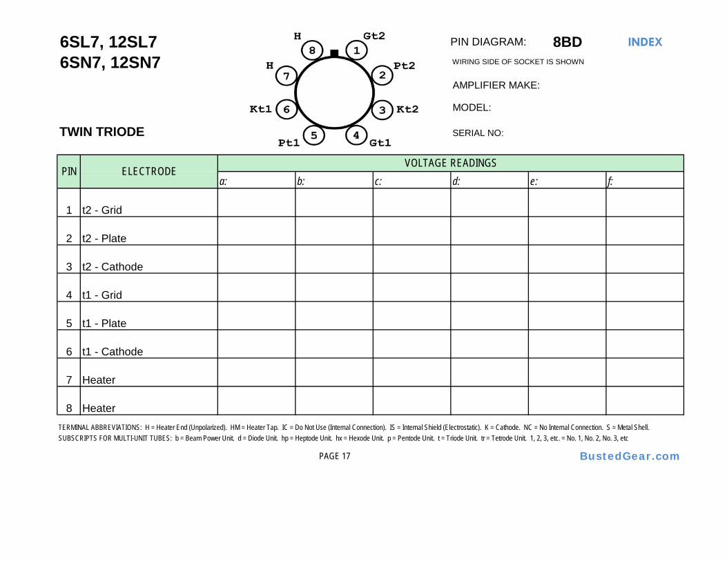
PIN DIAGRAM: 8BD INDEX
AMPLIFIER MAKE:
MODEL:
SERIAL NO:
a: b: c: d: e: f:
1 t2 - Grid
2 t2 - Plate
3 t2 - Cathode
4 t1 - Grid
5 t1 - Plate
6 t1 - Cathode
7 Heater
8 Heater
PAGE 17 BustedGear.com
6SL7, 12SL7
SUBSCRIPTS FOR MULTI-UNIT TUBES: b = Beam Power Unit. d = Diode Unit. hp = Heptode Unit. hx = Hexode Unit. p = Pentode Unit. t = Triode Unit. tr = Tetrode Unit. 1, 2, 3, etc. = No. 1, No. 2, No. 3, etc
6SN7, 12SN7
VOLTAGE READINGS
TWIN TRIODE
TERMINAL ABBREVIATIONS: H = Heater End (Unpolarized). HM = Heater Tap. IC = Do Not Use (Internal Connection). IS = Internal Shield (Electrostatic). K = Cathode. NC = No Internal Connection. S = Metal Shell.
WIRING SIDE OF SOCKET IS SHOWN
PIN ELECTRODE

PIN DIAGRAM: 8ET INDEX
AMPLIFIER MAKE:
MODEL:
SERIAL NO:
a: b: c: d: e: f:
1 Suppressor Grid
2 Heater
3 Plate
4 Screen Grid
5 Control Grid
6 NC
7 Heater
8 Cathode
PAGE 18 BustedGear.com
6CA7 / EL34
SUBSCRIPTS FOR MULTI-UNIT TUBES: b = Beam Power Unit. d = Diode Unit. hp = Heptode Unit. hx = Hexode Unit. p = Pentode Unit. t = Triode Unit. tr = Tetrode Unit. 1, 2, 3, etc. = No. 1, No. 2, No. 3, etc
KT88
VOLTAGE READINGS
POWER PENTODE
TERMINAL ABBREVIATIONS: H = Heater End (Unpolarized). HM = Heater Tap. IC = Do Not Use (Internal Connection). IS = Internal Shield (Electrostatic). K = Cathode. NC = No Internal Connection. S = Metal Shell.
WIRING SIDE OF SOCKET IS SHOWN
PIN ELECTRODE
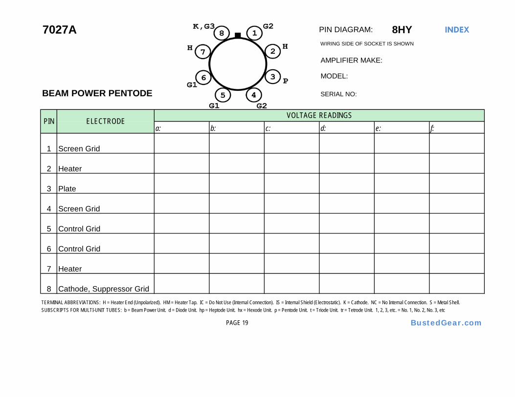
PIN DIAGRAM: 8HY INDEX
AMPLIFIER MAKE:
MODEL:
BEAM POWER PENTODE SERIAL NO:
a: b: c: d: e: f:
1 Screen Grid
2 Heater
3 Plate
4 Screen Grid
5 Control Grid
6 Control Grid
7 Heater
8 Cathode, Suppressor Grid
PAGE 19 BustedGear.com
7027A
SUBSCRIPTS FOR MULTI-UNIT TUBES: b = Beam Power Unit. d = Diode Unit. hp = Heptode Unit. hx = Hexode Unit. p = Pentode Unit. t = Triode Unit. tr = Tetrode Unit. 1, 2, 3, etc. = No. 1, No. 2, No. 3, etc
VOLTAGE READINGS
TERMINAL ABBREVIATIONS: H = Heater End (Unpolarized). HM = Heater Tap. IC = Do Not Use (Internal Connection). IS = Internal Shield (Electrostatic). K = Cathode. NC = No Internal Connection. S = Metal Shell.
WIRING SIDE OF SOCKET IS SHOWN
PIN ELECTRODE

PIN DIAGRAM: 8KQ INDEX
AMPLIFIER MAKE:
MODEL:
SERIAL NO:
a: b: c: d: e: f:
1
2 Heater
3 Plate
4 Screen Grid
5 Cathode, Suppressor Grid
6 Control Grid
7 Heater
8 Screen Grid
PAGE 20 BustedGear.com
7591A
SUBSCRIPTS FOR MULTI-UNIT TUBES: b = Beam Power Unit. d = Diode Unit. hp = Heptode Unit. hx = Hexode Unit. p = Pentode Unit. t = Triode Unit. tr = Tetrode Unit. 1, 2, 3, etc. = No. 1, No. 2, No. 3, etc
VOLTAGE READINGS
POWER PENTODE
TERMINAL ABBREVIATIONS: H = Heater End (Unpolarized). HM = Heater Tap. IC = Do Not Use (Internal Connection). IS = Internal Shield (Electrostatic). K = Cathode. NC = No Internal Connection. S = Metal Shell.
WIRING SIDE OF SOCKET IS SHOWN
PIN ELECTRODE

PIN DIAGRAM: 8N INDEX
AMPLIFIER MAKE:
MODEL:
SHARP-CUTOFF PENTODE SERIAL NO:
a: b: c: d: e: f:
1 Metal Shell
2 Heater
3 Suppressor Grid
4 Control Grid
5 Cathode
6 Screen Grid
7 Heater
8 Plate
PAGE 21 BustedGear.com
6SJ7
SUBSCRIPTS FOR MULTI-UNIT TUBES: b = Beam Power Unit. d = Diode Unit. hp = Heptode Unit. hx = Hexode Unit. p = Pentode Unit. t = Triode Unit. tr = Tetrode Unit. 1, 2, 3, etc. = No. 1, No. 2, No. 3, etc
VOLTAGE READINGS
TERMINAL ABBREVIATIONS: H = Heater End (Unpolarized). HM = Heater Tap. IC = Do Not Use (Internal Connection). IS = Internal Shield (Electrostatic). K = Cathode. NC = No Internal Connection. S = Metal Shell.
WIRING SIDE OF SOCKET IS SHOWN
PIN ELECTRODE

PIN DIAGRAM: 8S INDEX
AMPLIFIER MAKE:
MODEL:
SERIAL NO:
a: b: c: d: e: f:
1 Metal Shell
2 t2 - Plate
3 t2 - Grid
4 t1 - Grid
5 t1 - Plate
6 Common Cathode
7 Heater
8 Heater
PAGE 22 BustedGear.com
6SC7
SUBSCRIPTS FOR MULTI-UNIT TUBES: b = Beam Power Unit. d = Diode Unit. hp = Heptode Unit. hx = Hexode Unit. p = Pentode Unit. t = Triode Unit. tr = Tetrode Unit. 1, 2, 3, etc. = No. 1, No. 2, No. 3, etc
VOLTAGE READINGS
HIGH-MU TWIN TRIODE
TERMINAL ABBREVIATIONS: H = Heater End (Unpolarized). HM = Heater Tap. IC = Do Not Use (Internal Connection). IS = Internal Shield (Electrostatic). K = Cathode. NC = No Internal Connection. S = Metal Shell.
WIRING SIDE OF SOCKET IS SHOWN
PIN ELECTRODE
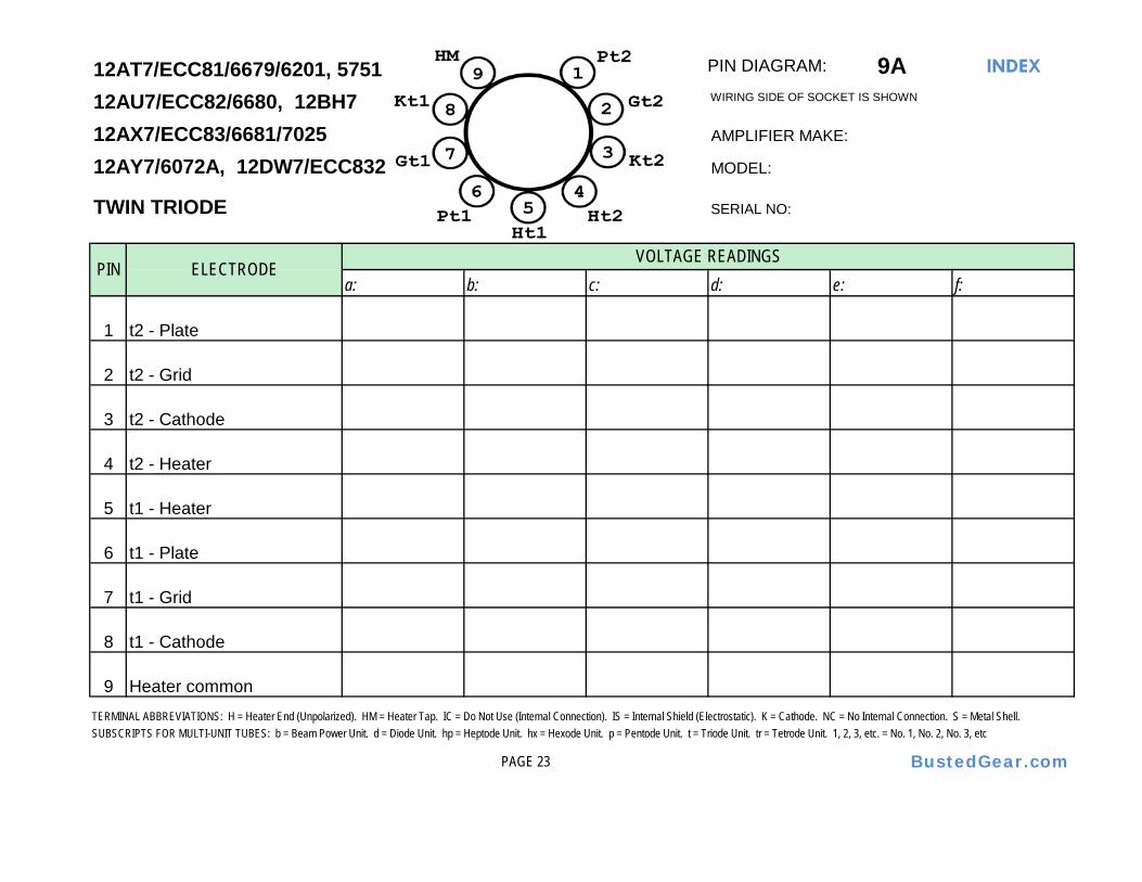
PIN DIAGRAM: 9A INDEX
AMPLIFIER MAKE:
MODEL:
SERIAL NO:
a: b: c: d: e: f:
1 t2 - Plate
2 t2 - Grid
3 t2 - Cathode
4 t2 - Heater
5 t1 - Heater
6 t1 - Plate
7 t1 - Grid
8 t1 - Cathode
9 Heater common
PAGE 23 BustedGear.com
TERMINAL ABBREVIATIONS: H = Heater End (Unpolarized). HM = Heater Tap. IC = Do Not Use (Internal Connection). IS = Internal Shield (Electrostatic). K = Cathode. NC = No Internal Connection. S = Metal Shell.SUBSCRIPTS FOR MULTI-UNIT TUBES: b = Beam Power Unit. d = Diode Unit. hp = Heptode Unit. hx = Hexode Unit. p = Pentode Unit. t = Triode Unit. tr = Tetrode Unit. 1, 2, 3, etc. = No. 1, No. 2, No. 3, etc
WIRING SIDE OF SOCKET IS SHOWN
VOLTAGE READINGS
TWIN TRIODE
12AT7/ECC81/6679/6201, 575112AU7/ECC82/6680, 12BH712AX7/ECC83/6681/702512AY7/6072A, 12DW7/ECC832
PIN ELECTRODE

PIN DIAGRAM: 9AJ INDEX
5BS8AMPLIFIER MAKE:
MODEL:
MEDIUM-MU TWIN TRIODE SERIAL NO:
a: b: c: d: e: f:
1 t2 - Plate
2 t2 - Grid
3 t2 - Cathode
4 t2 - Heater
5 t1 - Heater
6 t1 - Plate
7 t1 - Grid
8 t1 - Cathode
9 IS
PAGE 24
6DJ8/ECC88/6922
PIN ELECTRODE
BustedGear.com
VOLTAGE READINGS
TERMINAL ABBREVIATIONS: H = Heater End (Unpolarized). HM = Heater Tap. IC = Do Not Use (Internal Connection). IS = Internal Shield (Electrostatic). K = Cathode. NC = No Internal Connection. S = Metal Shell.SUBSCRIPTS FOR MULTI-UNIT TUBES: b = Beam Power Unit. d = Diode Unit. hp = Heptode Unit. hx = Hexode Unit. p = Pentode Unit. t = Triode Unit. tr = Tetrode Unit. 1, 2, 3, etc. = No. 1, No. 2, No. 3, etc
WIRING SIDE OF SOCKET IS SHOWN

PIN DIAGRAM: 9BF INDEX
AMPLIFIER MAKE:
MODEL:
SHARP-CUTOFF PENTODE SERIAL NO:
a: b: c: d: e: f:
1 Cathode
2 Control Grid
3 Suppressor Grid, IS
4 Heater
5 Heater
6 Heater common
7 Plate
8 Screen Grid
9 Suppressor Grid, IS
PAGE 25
12BY7A/12BV7/12DQ7
PIN ELECTRODE
BustedGear.com
VOLTAGE READINGS
TERMINAL ABBREVIATIONS: H = Heater End (Unpolarized). HM = Heater Tap. IC = Do Not Use (Internal Connection). IS = Internal Shield (Electrostatic). K = Cathode. NC = No Internal Connection. S = Metal Shell.SUBSCRIPTS FOR MULTI-UNIT TUBES: b = Beam Power Unit. d = Diode Unit. hp = Heptode Unit. hx = Hexode Unit. p = Pentode Unit. t = Triode Unit. tr = Tetrode Unit. 1, 2, 3, etc. = No. 1, No. 2, No. 3, etc
WIRING SIDE OF SOCKET IS SHOWN

PIN DIAGRAM: 9CV INDEX
7189A - pins 1 & 2 connect; pins 6 & 9 connect AMPLIFIER MAKE:
MODEL:
SERIAL NO:
a: b: c: d: e: f:
1 IC
2 Control Grid
3 Cathode, Suppressor Grid
4 Heater
5 Heater
6 IC
7 Plate
8 IC
9 Screen Grid
PAGE 26
6BQ5 / EL84
PIN ELECTRODE
BustedGear.com
WIRING SIDE OF SOCKET IS SHOWN
SUBSCRIPTS FOR MULTI-UNIT TUBES: b = Beam Power Unit. d = Diode Unit. hp = Heptode Unit. hx = Hexode Unit. p = Pentode Unit. t = Triode Unit. tr = Tetrode Unit. 1, 2, 3, etc. = No. 1, No. 2, No. 3, etc
7189
VOLTAGE READINGS
POWER PENTODE
TERMINAL ABBREVIATIONS: H = Heater End (Unpolarized). HM = Heater Tap. IC = Do Not Use (Internal Connection). IS = Internal Shield (Electrostatic). K = Cathode. NC = No Internal Connection. S = Metal Shell.
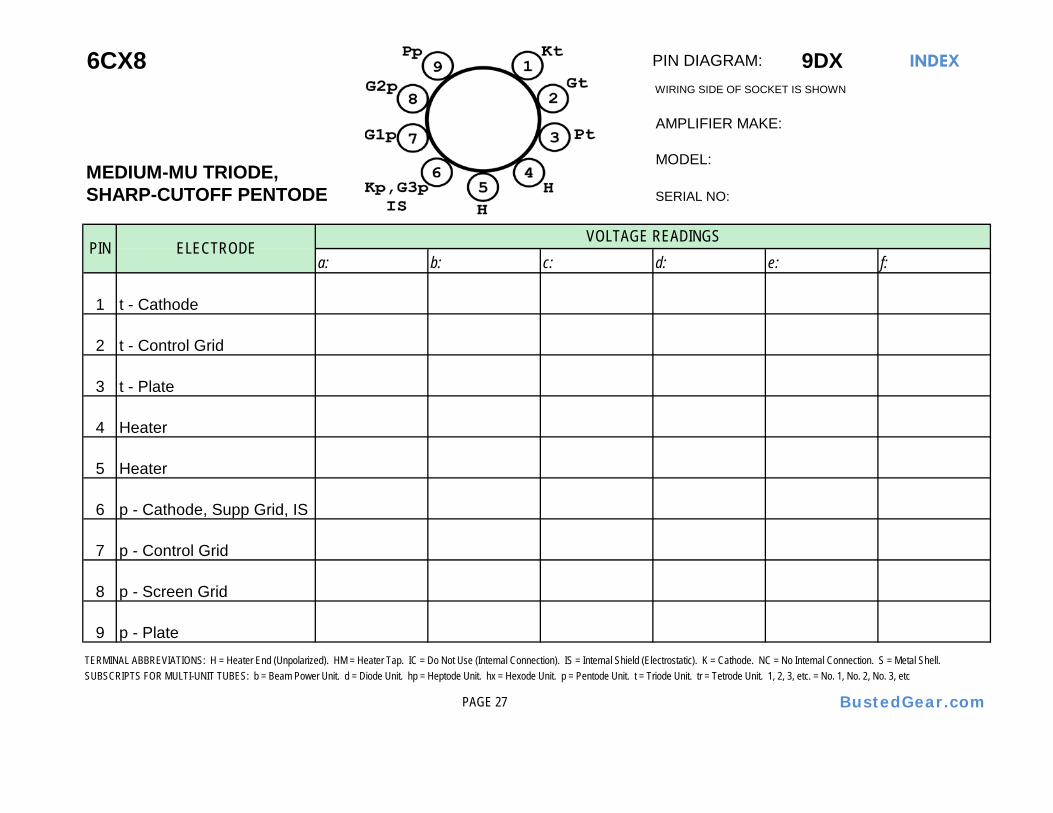
PIN DIAGRAM: 9DX INDEX
AMPLIFIER MAKE:
MEDIUM-MU TRIODE,MODEL:
SHARP-CUTOFF PENTODE SERIAL NO:
a: b: c: d: e: f:
1 t - Cathode
2 t - Control Grid
3 t - Plate
4 Heater
5 Heater
6 p - Cathode, Supp Grid, IS
7 p - Control Grid
8 p - Screen Grid
9 p - Plate
PAGE 27 BustedGear.com
VOLTAGE READINGS
TERMINAL ABBREVIATIONS: H = Heater End (Unpolarized). HM = Heater Tap. IC = Do Not Use (Internal Connection). IS = Internal Shield (Electrostatic). K = Cathode. NC = No Internal Connection. S = Metal Shell.SUBSCRIPTS FOR MULTI-UNIT TUBES: b = Beam Power Unit. d = Diode Unit. hp = Heptode Unit. hx = Hexode Unit. p = Pentode Unit. t = Triode Unit. tr = Tetrode Unit. 1, 2, 3, etc. = No. 1, No. 2, No. 3, etc
6CX8WIRING SIDE OF SOCKET IS SHOWN
PIN ELECTRODE

PIN DIAGRAM: 9EU INDEX
AMPLIFIER MAKE:
MODEL:
SERIAL NO:
a: b: c: d: e: f:
1 Screen Grid
2 NC
3 Control Grid
4 Heater
5 Heater
6 Control Grid
7 Cathode, Suppressor Grid
8 Screen Grid
9 Plate
PAGE 28
TERMINAL ABBREVIATIONS: H = Heater End (Unpolarized). HM = Heater Tap. IC = Do Not Use (Internal Connection). IS = Internal Shield (Electrostatic). K = Cathode. NC = No Internal Connection. S = Metal Shell.SUBSCRIPTS FOR MULTI-UNIT TUBES: b = Beam Power Unit. d = Diode Unit. hp = Heptode Unit. hx = Hexode Unit. p = Pentode Unit. t = Triode Unit. tr = Tetrode Unit. 1, 2, 3, etc. = No. 1, No. 2, No. 3, etc
BustedGear.com
6973WIRING SIDE OF SOCKET IS SHOWN
BEAM POWER TUBE
PIN ELECTRODEVOLTAGE READINGS

PIN DIAGRAM: 9EX INDEX
50BM8/UCL82AMPLIFIER MAKE:
HIGH-MU TRIODE,MODEL:
POWER PENTODE SERIAL NO:
a: b: c: d: e: f:
1 t - Grid
2 p - Cathode, Supp Grid, IS
3 p - Control Grid
4 Heater
5 Heater
6 p - Plate
7 p - Screen Grid
8 t - Cathode
9 t - Plate
PAGE 29 BustedGear.com
VOLTAGE READINGS
TERMINAL ABBREVIATIONS: H = Heater End (Unpolarized). HM = Heater Tap. IC = Do Not Use (Internal Connection). IS = Internal Shield (Electrostatic). K = Cathode. NC = No Internal Connection. S = Metal Shell.SUBSCRIPTS FOR MULTI-UNIT TUBES: b = Beam Power Unit. d = Diode Unit. hp = Heptode Unit. hx = Hexode Unit. p = Pentode Unit. t = Triode Unit. tr = Tetrode Unit. 1, 2, 3, etc. = No. 1, No. 2, No. 3, etc
6BM8/ECL82WIRING SIDE OF SOCKET IS SHOWN
PIN ELECTRODE

PIN DIAGRAM: 9FA INDEX
6FV8A5BR8/5FV8 AMPLIFIER MAKE:
MEDIUM-MU TRIODE,MODEL:
SHARP-CUTOFF PENTODE SERIAL NO:
a: b: c: d: e: f:
1 t - Grid
2 t - Plate
3 t - Cathode
4 Heater
5 Heater
6 p - Plate
7 p - Screen Grid
8 p - Cathode, Supp Grid, IS
9 p - Control Grid
PAGE 30 BustedGear.com
VOLTAGE READINGS
TERMINAL ABBREVIATIONS: H = Heater End (Unpolarized). HM = Heater Tap. IC = Do Not Use (Internal Connection). IS = Internal Shield (Electrostatic). K = Cathode. NC = No Internal Connection. S = Metal Shell.SUBSCRIPTS FOR MULTI-UNIT TUBES: b = Beam Power Unit. d = Diode Unit. hp = Heptode Unit. hx = Hexode Unit. p = Pentode Unit. t = Triode Unit. tr = Tetrode Unit. 1, 2, 3, etc. = No. 1, No. 2, No. 3, etc
6BR8AWIRING SIDE OF SOCKET IS SHOWN
PIN ELECTRODE

PIN DIAGRAM: 9HN INDEX
AMPLIFIER MAKE:
MODEL:
SERIAL NO:
a: b: c: d: e: f:
1 Screen Grid
2 NC
3 Control Grid
4 Heater
5 Heater
6 Control Grid
7 Cathode, Suppressor Grid
8 IC
9 Plate
PAGE 31
TERMINAL ABBREVIATIONS: H = Heater End (Unpolarized). HM = Heater Tap. IC = Do Not Use (Internal Connection). IS = Internal Shield (Electrostatic). K = Cathode. NC = No Internal Connection. S = Metal Shell.SUBSCRIPTS FOR MULTI-UNIT TUBES: b = Beam Power Unit. d = Diode Unit. hp = Heptode Unit. hx = Hexode Unit. p = Pentode Unit. t = Triode Unit. tr = Tetrode Unit. 1, 2, 3, etc. = No. 1, No. 2, No. 3, etc
BustedGear.com
6CZ5WIRING SIDE OF SOCKET IS SHOWN
BEAM POWER TUBE
PIN ELECTRODEVOLTAGE READINGS

PIN DIAGRAM: 9JT INDEX
AMPLIFIER MAKE:
MEDIUM-MU TRIODE,MODEL:
SHARP-CUTOFF PENTODE SERIAL NO:
a: b: c: d: e: f:
1 t - Plate
2 p - Plate
3 p - Screen Grid
4 Heater
5 Heater
6 p - Cathode, Supp Grid, IS
7 p - Control Grid
8 t - Cathode
9 t - Grid
PAGE 32 BustedGear.com
VOLTAGE READINGS
TERMINAL ABBREVIATIONS: H = Heater End (Unpolarized). HM = Heater Tap. IC = Do Not Use (Internal Connection). IS = Internal Shield (Electrostatic). K = Cathode. NC = No Internal Connection. S = Metal Shell.SUBSCRIPTS FOR MULTI-UNIT TUBES: b = Beam Power Unit. d = Diode Unit. hp = Heptode Unit. hx = Hexode Unit. p = Pentode Unit. t = Triode Unit. tr = Tetrode Unit. 1, 2, 3, etc. = No. 1, No. 2, No. 3, etc
7199WIRING SIDE OF SOCKET IS SHOWN
PIN ELECTRODE

PIN DIAGRAM: 9LP INDEX
AMPLIFIER MAKE:
MODEL:
MEDIUM-MU TWIN TRIODE SERIAL NO:
a: b: c: d: e: f:
1 t2 - Plate
2 t2 - Grid
3 t2 - Cathode
4 Heater
5 Heater
6 t1 - Plate
7 t1 - Grid
8 t1 - Cathode
9 NC
PAGE 33
6FQ76CG7
PIN ELECTRODE
BustedGear.com
VOLTAGE READINGS
TERMINAL ABBREVIATIONS: H = Heater End (Unpolarized). HM = Heater Tap. IC = Do Not Use (Internal Connection). IS = Internal Shield (Electrostatic). K = Cathode. NC = No Internal Connection. S = Metal Shell.SUBSCRIPTS FOR MULTI-UNIT TUBES: b = Beam Power Unit. d = Diode Unit. hp = Heptode Unit. hx = Hexode Unit. p = Pentode Unit. t = Triode Unit. tr = Tetrode Unit. 1, 2, 3, etc. = No. 1, No. 2, No. 3, etc
WIRING SIDE OF SOCKET IS SHOWN

PIN DIAGRAM: 9LS INDEX
AMPLIFIER MAKE:
MODEL:
SERIAL NO:
a: b: c: d: e: f:
1 Heater
2 Heater
3 NC
4 t2 - Cathode
5 t2 - Grid
6 t2 - Plate
7 t1 - Plate
8 t1 - Grid
9 t1 - Cathode
PAGE 34
6EU7
PIN ELECTRODE
BustedGear.com
TERMINAL ABBREVIATIONS: H = Heater End (Unpolarized). HM = Heater Tap. IC = Do Not Use (Internal Connection). IS = Internal Shield (Electrostatic). K = Cathode. NC = No Internal Connection. S = Metal Shell.SUBSCRIPTS FOR MULTI-UNIT TUBES: b = Beam Power Unit. d = Diode Unit. hp = Heptode Unit. hx = Hexode Unit. p = Pentode Unit. t = Triode Unit. tr = Tetrode Unit. 1, 2, 3, etc. = No. 1, No. 2, No. 3, etc
WIRING SIDE OF SOCKET IS SHOWN
VOLTAGE READINGS
TWIN TRIODE

PIN DIAGRAM: 9LZ INDEX
AMPLIFIER MAKE:
HIGH-MU TRIODE, MODEL:
SHARP-CUTOFF PENTODE SERIAL NO:
a: b: c: d: e: f:
1 t - Grid
2 t - Cathode
3 p - Screen Grid
4 Heater
5 Heater
6 p - Plate
7 p - Cathode, Supp Grid, IS
8 p - Control Grid
9 t - Plate
PAGE 35
SUBSCRIPTS FOR MULTI-UNIT TUBES: b = Beam Power Unit. d = Diode Unit. hp = Heptode Unit. hx = Hexode Unit. p = Pentode Unit. t = Triode Unit. tr = Tetrode Unit. 1, 2, 3, etc. = No. 1, No. 2, No. 3, etc
BustedGear.com
6GW8/ECL86WIRING SIDE OF SOCKET IS SHOWN
VOLTAGE READINGS
TERMINAL ABBREVIATIONS: H = Heater End (Unpolarized). HM = Heater Tap. IC = Do Not Use (Internal Connection). IS = Internal Shield (Electrostatic). K = Cathode. NC = No Internal Connection. S = Metal Shell.
PIN ELECTRODE

PIN DIAGRAM: 9M INDEX
AMPLIFIER MAKE:
MODEL:
SERIAL NO:
a: b: c: d: e: f:
1 d1 - Plate
2 NC
3 Cathode
4 Heater
5 Heater
6 NC
7 d2 - Plate
8 NC
9 NC
PAGE 36
6CA4 / EZ81
PIN ELECTRODE
BustedGear.com
WIRING SIDE OF SOCKET IS SHOWN
SUBSCRIPTS FOR MULTI-UNIT TUBES: b = Beam Power Unit. d = Diode Unit. hp = Heptode Unit. hx = Hexode Unit. p = Pentode Unit. t = Triode Unit. tr = Tetrode Unit. 1, 2, 3, etc. = No. 1, No. 2, No. 3, etc
6V4 / EZ80
VOLTAGE READINGS
FULL-WAVE RECTIFIER
TERMINAL ABBREVIATIONS: H = Heater End (Unpolarized). HM = Heater Tap. IC = Do Not Use (Internal Connection). IS = Internal Shield (Electrostatic). K = Cathode. NC = No Internal Connection. S = Metal Shell.

PIN DIAGRAM: 9RW INDEX
AMPLIFIER MAKE:
MODEL:
SERIAL NO:
a: b: c: d: e: f:
1 Screen Grid
2 Control Grid
3 Cathode, Suppressor Grid
4 Heater
5 Heater
6 Control Grid
7 Screen Grid
8 Limited Connection
9 Plate
PAGE 37 BustedGear.com
7868
SUBSCRIPTS FOR MULTI-UNIT TUBES: b = Beam Power Unit. d = Diode Unit. hp = Heptode Unit. hx = Hexode Unit. p = Pentode Unit. t = Triode Unit. tr = Tetrode Unit. 1, 2, 3, etc. = No. 1, No. 2, No. 3, etc
VOLTAGE READINGS
POWER PENTODE
TERMINAL ABBREVIATIONS: H = Heater End (Unpolarized). HM = Heater Tap. IC = Do Not Use (Internal Connection). IS = Internal Shield (Electrostatic). K = Cathode. NC = No Internal Connection. S = Metal Shell.
WIRING SIDE OF SOCKET IS SHOWN
PIN ELECTRODE

PIN DIAGRAM: 12BQ INDEX
AMPLIFIER MAKE:
MODEL:
HIGH-MU TRIPLE TRIODE SERIAL NO:
a: b: c: d: e: f:
1 Heater
2 t3 - Plate
3 t3 - Cathode
4 t1 - Cathode
5 t2 - Plate
6 t2 - Cathode
7 t2 - Grid
8 IC
9 t1 - Grid
10 t1 - Plate
11 t3 - Grid
12 Heater
PAGE 38 BustedGear.com
VOLTAGE READINGS
TERMINAL ABBREVIATIONS: H = Heater End (Unpolarized). HM = Heater Tap. IC = Do Not Use (Internal Connection). IS = Internal Shield (Electrostatic). K = Cathode. NC = No Internal Connection. S = Metal Shell.SUBSCRIPTS FOR MULTI-UNIT TUBES: b = Beam Power Unit. d = Diode Unit. hp = Heptode Unit. hx = Hexode Unit. p = Pentode Unit. t = Triode Unit. tr = Tetrode Unit. 1, 2, 3, etc. = No. 1, No. 2, No. 3, etc
6C10WIRING SIDE OF SOCKET IS SHOWN
PIN ELECTRODE

PIN DIAGRAM: 12BY INDEX
AMPLIFIER MAKE:
MODEL:
THREE-UNIT TRIODE SERIAL NO:
a: b: c: d: e: f:
1 Heater
2 t3 - Plate
3 t3 - Cathode
4 t1 - Cathode
5 t2 - Plate
6 t2 - Cathode
7 t2 - Grid
8 IS
9 t1 - Grid
10 t1 - Plate
11 t3 - Grid
12 Heater
PAGE 39 BustedGear.com
VOLTAGE READINGS
TERMINAL ABBREVIATIONS: H = Heater End (Unpolarized). HM = Heater Tap. IC = Do Not Use (Internal Connection). IS = Internal Shield (Electrostatic). K = Cathode. NC = No Internal Connection. S = Metal Shell.SUBSCRIPTS FOR MULTI-UNIT TUBES: b = Beam Power Unit. d = Diode Unit. hp = Heptode Unit. hx = Hexode Unit. p = Pentode Unit. t = Triode Unit. tr = Tetrode Unit. 1, 2, 3, etc. = No. 1, No. 2, No. 3, etc
6K11/6Q11WIRING SIDE OF SOCKET IS SHOWN
PIN ELECTRODE