vacuum products - exotic automation 0802-e vacuum products distributor network, warning, ... = 10kg...
TRANSCRIPT
ENGINEERING YOUR SUCCESS.
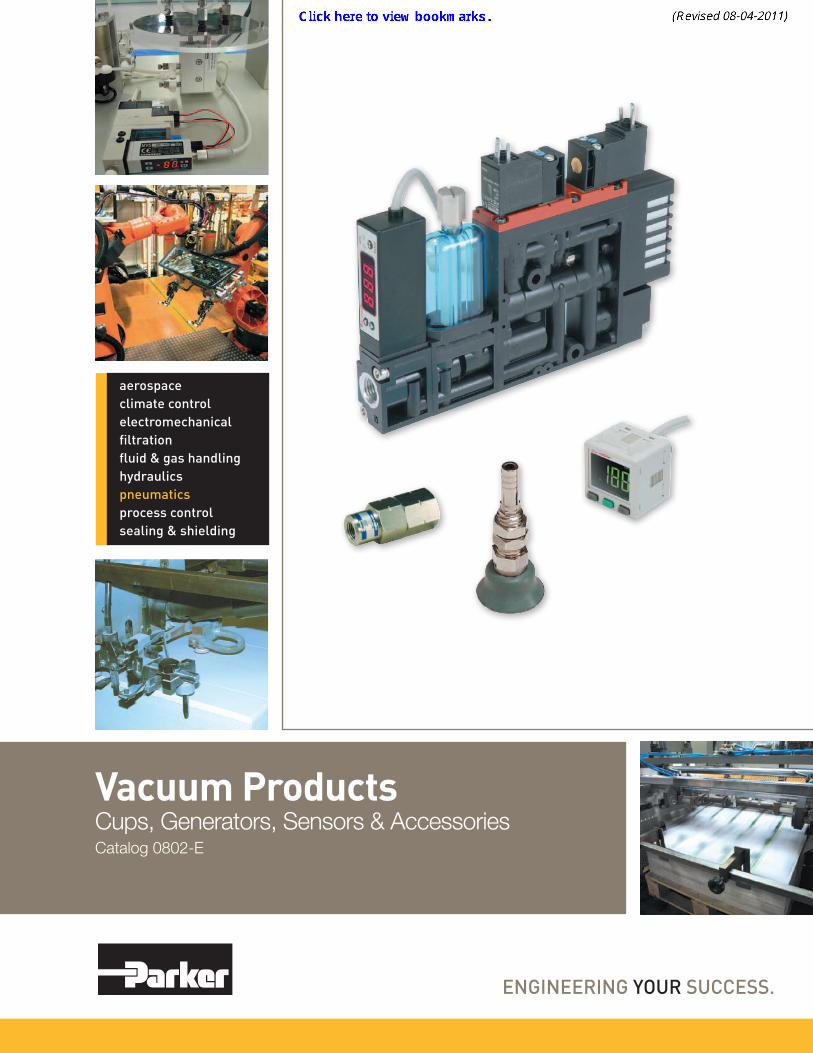
Vacuum ProductsCups, Generators, Sensors & AccessoriesCatalog 0802-E
aerospaceclimate controlelectromechanicalfiltrationfluid & gas handlinghydraulicspneumaticsprocess controlsealing & shielding
Parker Hannifin CorporationPneumatic DivisionRichland, Michiganwww.parker.com/pneumatics
! WARNINGFAILURE OR IMPROPER SELECTION OR IMPROPER USE OF THE PRODUCTS AND/OR SYSTEMS DESCRIBED HEREIN OR RELATED ITEMS CAN CAUSE DEATH, PERSONAL INJURY AND PROPERTY DAMAGE.This document and other information from Parker Hannifin Corporation, its subsidiaries and authorized distributors provide product and/or system options for further investigation by users having technical expertise. It is important that you analyze all aspects of your application including consequences of any failure, and review the information concerning the product or system in the current product catalog. Due to the variety of operating conditions and applications for these products or systems, the user, through its own analysis and testing, is solely responsible for making the final selection of the products and systems and assuring that all performance, safety and warning requirements of the application are met.The products described herein, including without limitation, product features, specifications, designs, availability and pricing, are subject to change by Parker Hannifin Corporation and its subsidiaries at any time without notice.
Offer of SaleThe items described in this document are hereby offered for sale by Parker Hannifin Corporation, its subsidiaries or its authorized distributors. This offer and its acceptance are governed by the provisions stated on the separate page of this document entitled “Offer of Sale”.
© Copyright 2010 Parker Hannifin Corporation. All Rights Reserved
Vacuum ProductsCatalog 0802-E
Distributor Network, Warning, Offer of Sale
DISTRIBUTION NETWORKAt Parker, we have the largest global distribution
network in motion and control, with over 7,500 distributors serving more than 422,000 customers.
To find the distributor nearest you, please visit our DISTRIBUTOR LOCATOR at
http://www.parker.com/pneu/distributor
ENGINEERING YOUR SUCCESS.
Parker Hannifin CorporationPneumatic DivisionRichland, Michiganwww.parker.com/pneumatics
1
Pneumatic Control ComponentsProduct Selection Chart
Catalog 0802-E
Index
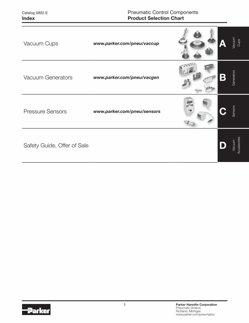
Vacuum Cups www.parker.com/pneu/vaccup A
Vacuum Generators www.parker.com/pneu/vacgen B
Pressure Sensors www.parker.com/pneu/sensors C
Safety Guide, Offer of Sale D
Saf
ety
Gui
de,
Offe
r of
Sal
eVa
cuum
Acc
esso
ries
Sen
sors
Gen
erat
ors
Vacu
um
Cup
s
2 Parker Hannifin CorporationPneumatic DivisionRichland, Michiganwww.parker.com/pneumatics
A
TechnicalPFG Flat
PBG Bellow
sP5V-CFS
FlatPJG Short Bellow
sPCG
Multiple
Bellows
PUGB Flat Sw
ivelCup
Fittings
Pneumatic Control ComponentsCatalog 0802-E
Systems
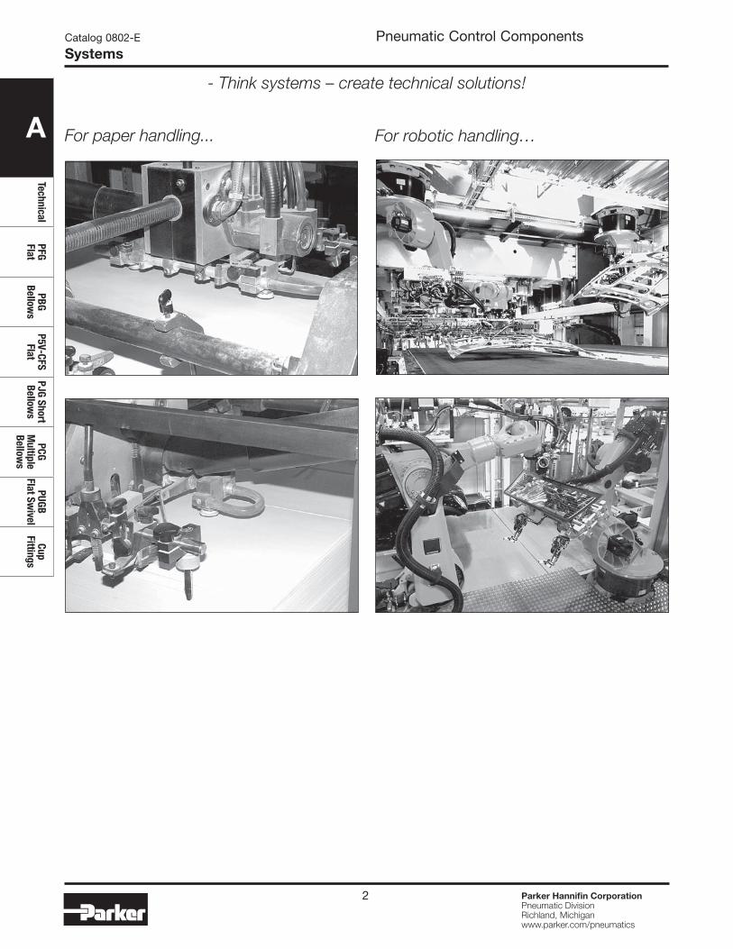
- Think systems – create technical solutions!
For robotic handling…For paper handling...
A
Tech
nica
lPF
G Fl
atPB
G Be
llow
sP5
V-CF
S Fl
atPJ
G Sh
ort
Bello
ws
PCG
Mul
tiple
Be
llow
s
PUGB
Fl
at S
wiv
elCu
p Fi
tting
s
A1 Parker Hannifin CorporationPneumatic DivisionRichland, Michiganwww.parker.com/pneumatics
Vacuum Cups
Section Awww.parker.com/pneu/vaccup
A
TechnicalPFG Flat
PBG Bellow
sP5V-CFS
FlatPJG Short Bellow
sPCG
Multiple
Bellows
PUGB Flat Sw
ivelCup
Fittings
Parker Hannifin CorporationPneumatic DivisionRichland, Michiganwww.parker.com/pneumatics
A2
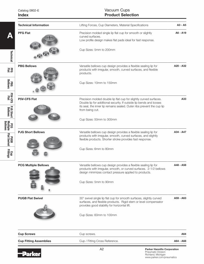
Technical Information Lifting Forces, Cup Diameters, Material Specifications A3 - A5
PFG Flat Precision molded single lip flat cup for smooth or slightly curved surfaces. Low profile design makes flat pads ideal for fast response.
Cup Sizes: 5mm to 200mm
A6 - A19
PBG Bellows Versatile bellows cup design provides a flexible sealing lip for products with irregular, smooth, curved surfaces, and flexible products.
Cup Sizes: 10mm to 150mm
A20 - A32
P5V-CFS Flat Precision molded double lip flat cup for slightly curved surfaces. Double lip for additional security. If outside lip bends and looses its seal, the inner lip remains sealed. Outer ribs prevent the cup lip from being cut.
Cup Sizes: 50mm to 300mm
A33
PJG Short Bellows Versatile bellows cup design provides a flexible sealing lip for products with irregular, smooth, curved surfaces, and slightly flexible products. Shorter stroke provides fast response.
Cup Sizes: 6mm to 80mm
A34 - A47
PCG Multiple Bellows Versatile bellows cup design provides a flexible sealing lip for products with irregular, smooth, or curved surfaces. 2-1/2 bellows design minimizes contact pressure applied to products.
Cup Sizes: 5mm to 90mm
A48 - A58
PUGB Flat Swivel 30° swivel single lip flat cup for smooth surfaces, slightly curved surfaces, and flexible products. Rigid stem or level compensator provides good stability for horizontal lift.
Cup Sizes: 60mm to 100mm
A59 - A63
Cup Screws Cup screws. A64
Cup Fitting Assemblies Cup / Fitting Cross Reference. A64 - A68
Vacuum CupsProduct Selection
Catalog 0802-E
Index
A3 Parker Hannifin CorporationPneumatic DivisionRichland, Michiganwww.parker.com/pneumatics
A
Tech
nica
lPF
G Fl
atPB
G Be
llow
sP5
V-CF
S Fl
atPJ
G Sh
ort
Bello
ws
PCG
Mul
tiple
Be
llow
s
PUGB
Fl
at S
wiv
elCu
p Fi
tting
s
Catalog 0802-E
Cup MaterialsVacuum CupsTechnical Information
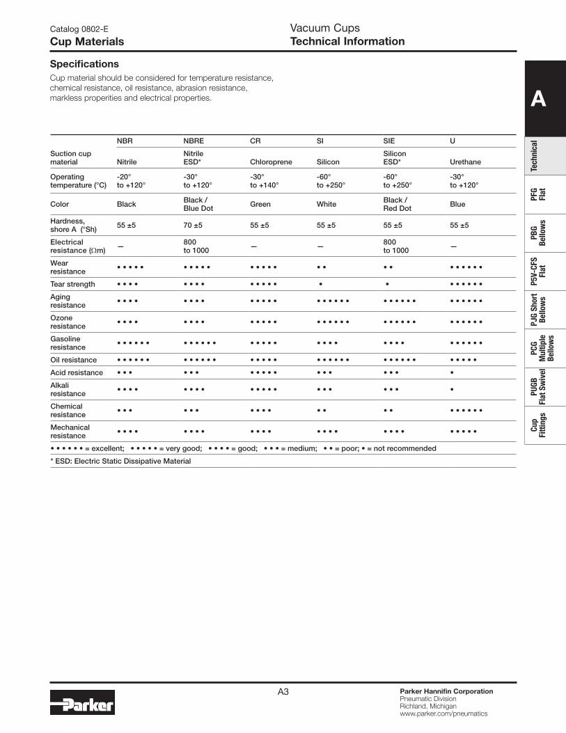
Suction cupmaterial
NBR NBRE CR SI SIE U
NitrileNitrileESD* Chloroprene Silicon
SiliconESD* Urethane
Operating temperature (°C)
-20° to +120°
-30° to +120°
-30° to +140°
-60° to +250°
-60° to +250°
-30° to +120°
Color Black Black / Blue Dot Green White Black /
Red Dot Blue
Hardness, shore A (°Sh) 55 ±5 70 ±5 55 ±5 55 ±5 55 ±5 55 ±5
Electrical resistance (Ωm) — 800
to 1000 — — 800 to 1000 —
Wear resistance • • • • • • • • • • • • • • • • • • • • • • • • •
Tear strength • • • • • • • • • • • • • • • • • • • • •
Aging resistance • • • • • • • • • • • • • • • • • • • • • • • • • • • • • • •
Ozone resistance • • • • • • • • • • • • • • • • • • • • • • • • • • • • • • •
Gasoline resistance • • • • • • • • • • • • • • • • • • • • • • • • • • • • • • •
Oil resistance • • • • • • • • • • • • • • • • • • • • • • • • • • • • • • • • • •
Acid resistance • • • • • • • • • • • • • • • • • •
Alkali resistance • • • • • • • • • • • • • • • • • • • •
Chemical resistance • • • • • • • • • • • • • • • • • • • •
Mechanical resistance • • • • • • • • • • • • • • • • • • • • • • • • •
• • • • • • = excellent; • • • • • = very good; • • • • = good; • • • = medium; • • = poor; • = not recommended
* ESD: Electric Static Dissipative Material
SpecificationsCup material should be considered for temperature resistance, chemical resistance, oil resistance, abrasion resistance, markless properities and electrical properties.
A4 Parker Hannifin CorporationPneumatic DivisionRichland, Michiganwww.parker.com/pneumatics
A
TechnicalPFG Flat
PBG Bellow
sP5V-CFS
FlatPJG Short Bellow
sPCG
Multiple
Bellows
PUGB Flat Sw
ivelCup
Fittings
Catalog 0802-E
Cup SelectionVacuum CupsTechnical Information
Selecting the proper vacuum cup
CAUTION:Selecting the type of vacuum cup, material, and size suitable for an application is important to the overall vacuum system. Calculating the forces involved for each application is recommended to determine the vacuum cup size. It should be noted that these calculations are basic theoretical guidelines and each application must be tested for actual results. With all vacuum applications, certain practical assumptions concerning cup materials, environmental conditions, and product characteristics to name a few, may not be consistent with the performance. Again, the user should determine the efficiency, performance, and safety factor of the cup selection.
Calculating pad diameter and forces
Mass The term mass is a quantity of matter and its ability to resist
motion when acted on by an external force. The magnitude of an object is represented as a certain number of kilograms (kg) and is symbolized as “m”. The easiest way to determine the mass of an object is to measure the weight with a scale within the earth’s gravitational field (ag = 9.81m/sec2). Likewise, outside of any gravitational field, a mass could potentially be weightless.
Forces For vacuum applications, force is a vector quantity in a
defined direction either horizontal or vertical. The standard international unit of force is measured in Newtons (N) which is the equivalent of (kgm/sec2). The force can be calculated by measuring the effect of a change in acceleration on a mass.
Newtons Law: F(N) = mass(kg) x ag(m/sec2)
Consider an object with a mass of 10kg. The gravitational force on this object would be:
F(N) = 10kg x 9.81m/sec2 = 98.1 N
Acceleration Acceleration is the change in velocity of a moving object.
Acceleration is a vector, a directional quantity expressed in units of meters per second squared (m/sec2) and symbolized as “a”. To explain the magnitude of acceleration consider an object with a change in velocity of 2 meters per second (m/sec) over a 4 second time frame. The acceleration can be calculated with: a = velocity a = 6m/sec a = 3m/sec2
time 2 sec
This is considered an average acceleration.
Coefficient of frictionCertain values for coefficient of friction should be taken into consideration when calculating the combined forces in motion. Actual values between suction cups and surfaces are difficult to determine. Therefore, coefficient of friction values from published charts, should be used as a reference to adjust the safety factors accordingly.
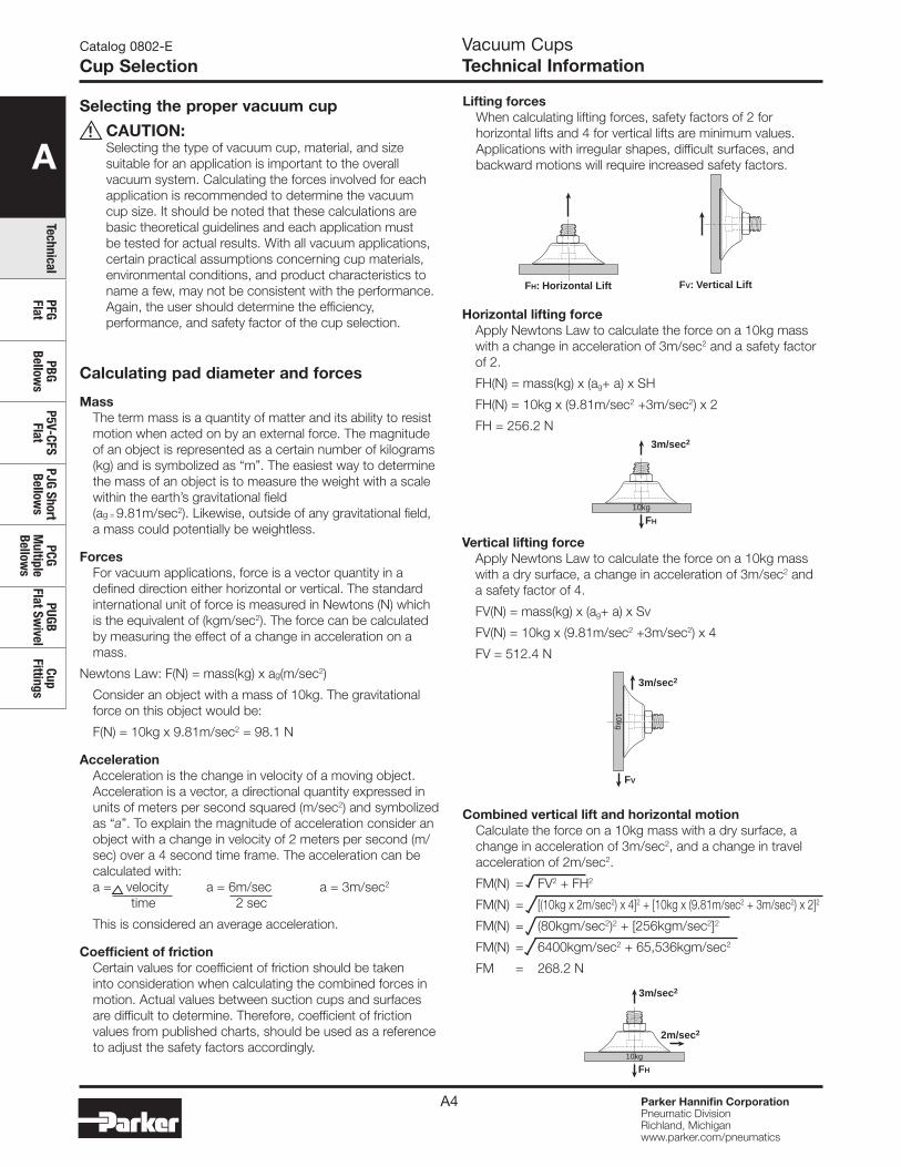
FH: Horizontal Lift FV: Vertical Lift
Horizontal lifting forceApply Newtons Law to calculate the force on a 10kg mass with a change in acceleration of 3m/sec2 and a safety factor of 2.
FH(N) = mass(kg) x (ag+ a) x SH
FH(N) = 10kg x (9.81m/sec2 +3m/sec2) x 2
FH = 256.2 N
FH
3m/sec2
10kg
FV
3m/sec2
10kg
FH
3m/sec2
2m/sec2
10kg
Lifting forcesWhen calculating lifting forces, safety factors of 2 for horizontal lifts and 4 for vertical lifts are minimum values. Applications with irregular shapes, difficult surfaces, and backward motions will require increased safety factors.
Vertical lifting forceApply Newtons Law to calculate the force on a 10kg mass with a dry surface, a change in acceleration of 3m/sec2 and a safety factor of 4.
FV(N) = mass(kg) x (ag+ a) x Sv
FV(N) = 10kg x (9.81m/sec2 +3m/sec2) x 4
FV = 512.4 N
Combined vertical lift and horizontal motionCalculate the force on a 10kg mass with a dry surface, a change in acceleration of 3m/sec2, and a change in travel acceleration of 2m/sec2.
FM(N) = FV2 + FH2
FM(N) = [(10kg x 2m/sec2) x 4]2 + [10kg x (9.81m/sec2 + 3m/sec2) x 2]2
FM(N) = (80kgm/sec2)2 + [256kgm/sec2]2
FM(N) = 6400kgm/sec2 + 65,536kgm/sec2
FM = 268.2 N
!
A5 Parker Hannifin CorporationPneumatic DivisionRichland, Michiganwww.parker.com/pneumatics
A
Tech
nica
lPF
G Fl
atPB
G Be
llow
sP5
V-CF
S Fl
atPJ
G Sh
ort
Bello
ws
PCG
Mul
tiple
Be
llow
s
PUGB
Fl
at S
wiv
elCu
p Fi
tting
s
Catalog 0802-E
Lift CapacityVacuum CupsTechnical Information
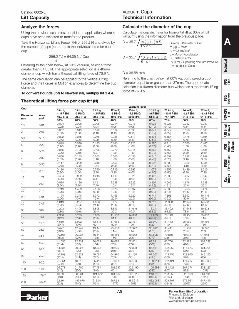
Analyze the forcesUsing the previous examples, consider an application where 4 cups have been selected to transfer the product.
Take the Horizontal Lifting Force (FH) of 256.2 N and divide by the number of cups (4) to obtain the individual force for each cup.
256.2 (N) = 64.05 N / Cup 4Referring to the chart below, at 60% vacuum, select a force greater than 64.05 N. The appropriate selection is a 40mm diameter cup which has a theoretical lifting force of 76.9 N.
The same calculation can be applied to the Vertical Lifting Force and the Forces in Motion examples to determine the cup diameter.
To convert Pounds (lbf) to Newton (N), multiply lbf x 4.4.
Calculate the diameter of the cupCalculate the cup diameter for horizontal lift at 60% of full vacuum using the information from the previous page.
D = 35.7 m (ag + a) x S Pv x n
D = 35.7 10 (9.81 + 3) x 2 61 x 4
D = 36.58 mm
Referring to the chart below, at 60% vacuum, select a cup diameter equal to or greater than 37mm. The appropriate selection is a 40mm diameter cup which has a theoretical lifting force of 76.9 N.
Theoretical lifting force per cup lbf (N)
CupVacuum level
3 inHg 6 inHg 9 inHg 12 inHg 15 inHg 18 inHg 21 inHg 24 inHg 27 inHg
Diametermm
Areacm2
-1.5 PSIG -3 PSIG -4.5 PSIG -6 PSIG -7.5 PSIG -9 PSIG -10.5 PSIG -12 PSIG -13.5 PSIG10.2 kPa 20.3 kPa 30.5 kPa 40.6 kPa 50.8 kPa 61 kPa 71.1 kPa 81.3 kPa 91.4 kPa10% 20% 30% 40% 50% 60% 70% 80% 90%
1.5 0.01 0.004(0.02)
0.008(0.04)
0.008(0.04)
0.014(0.06)
0.018(0.08)
0.022(0.10)
0.026(0.12)
0.032(0.14)
0.032(0.14)
2 0.03 0.007(0.03)
0.013(0.06)
0.022(0.10)
0.029(0.13)
0.036(0.16)
0.043(0.19)
0.049(0.22)
0.056(0.25)
0.063(0.28)
3.5 0.10 0.022(0.10)
0.045(0.20)
0.065(0.29)
0.088(0.39)
0.110(0.49)
0.133(0.59)
0.155(0.69)
0.175(0.78)
0.198(0.88)
5 0.20 0.045(0.20)
0.090(0.40)
0.135(0.60)
0.180(0.80)
0.225(1.00)
0.270(1.20)
0.315(1.40)
0.360(1.60)
0.405(1.80)
6 0.28 0.065(0.29)
0.130(0.58)
0.196(0.87)
0.270(1.20)
0.315(1.40)
0.382(1.70)
0.450(2.00)
0.517(2.30)
0.585(2.60)
7 0.39 0.088(0.39)
0.175(0.78)
0.265(1.18)
0.360(1.60)
0.450(2.00)
0.540(2.40)
0.607(2.70)
0.697(3.10)
0.787(3.50)
8 0.50 0.117(0.52)
0.229(1.02)
0.346(1.54)
0.450(2.00)
0.585(2.60)
0.697(3.10)
0.809(3.60)
0.922(4.10)
1.034(4.60)
10 0.79 0.180(0.80)
0.360(1.60)
0.540(2.40)
0.719(3.20)
0.899(4.00)
1.079(4.80)
1.259(5.60)
1.439(6.40)
1.619(7.20)
15 1.77 0.404(1.80)
0.809(3.60)
1.216(5.41)
1.619(7.20)
2.023(9.00)
2.428(10.8)
2.833(12.6)
2.237(14.4)
3.642(16.2)
18 2.55 0.585(2.60)
1.169(5.20)
1.751(7.79)
2.338(10.4)
2.923(13.0)
3.507(15.6)
4.069(18.1)
4.676(20.8)
5.238(23.3)
20 3.14 0.719(3.20)
1.439(6.40)
2.158(9.60)
2.878(12.8)
3.597(16.0)
4.316(19.2)
5.036(22.4)
5.755(25.6)
6.474(28.8)
25 4.91 1.124(5.00)
2.248(10.0)
3.372(15.0)
4.496(20.0)
5.620(25.0)
6.744(30.0)
7.868(35.0)
8.992(40.0)
10.116(45.0)
30 7.07 1.619(7.20)
3.237(14.4)
4.856(21.6)
6.474(28.8)
8.093(36.0)
9.712(43.2)
11.330(50.4)
12.949(57.6)
14.568(64.8)
35 9.62 2.203(9.80)
4.406(19.6)
5.598(29.4)
8.813(39.2)
11.016(49.0)
13.241(58.9)
15.422(68.6)
17.648(78.5)
19.828(88.2)
40 12.6 2.900(12.9)
5.755(25.6)
8.655(38.5)
11.510(51.2)
14.388(64.0)
17.288(76.9)
20.143(89.6)
23.155(103)
25.853(115)
50 19.6 4.519(20.1)
8.992(40.0)
13.511(60.1)
17.985(80.0)
22.481(100)
26.977(120)
31.473(140)
35.969(160)
40.466(180)
60 28.3 6.497(28.9)
12.949(57.6)
19.446(86.5)
25.853(115)
32.372(144)
38.892(173)
45.411(202)
51.931(231)
58.226(259)
75 44.2 10.161(45.2)
20.233(90.0)
30.349(135)
40.466(180)
50.582(225)
60.698(270)
70.815(315)
80.931(360)
91.048(405)
80 50.3 11.555(51.4)
22.931(102)
34.621(154)
46.086(205)
57.551(256)
69.241(308)
80.706(359)
92.172(410)
103.637(461)
90 63.6 14.635(65.1)
29.225(130)
43.838(195)
58.226(259)
72.838(324)
87.451(389)
102.063(454)
116.676(519)
131.064(583)
95 70.9 16.299(72.5)
32.372(144)
48.784(217)
64.970(289)
81.156(361)
97.567(434)
113.753(506)
129.940(578)
146.126(650)
110 95.0 21.851(97.2)
43.613(194)
65.419(291)
87.001(387)
108.808(484)
130.614(581)
152.421(678)
174.227(775)
195.809(871)
120 113.1 26.078(116)
51.706(230)
77.784(346)
103.637(461)
129.490(576)
155.568(692)
181.421(807)
207.274(922)
233.127(1037)
150 176.7 40.690(181)
80.931(360)
121.622(541)
161.862(720)
202.328(900)
243.019(1081)
283.259(1260)
323.950(1441)
364.191(1620)
200 314.2 72.164(321)
143.878(640)
216.041(961)
287.531(1279)
359.919(1601)
432.083(1922)
503.797(2241)
575.961(2562)
647.449(2880
D (mm) = Diameter of Cup m (kg) = Mass ag = 9.81m/sec2
a = Motion Acceleration S = Safety Factor Pv (kPa) = Operating Vacuum Pressure n = number of Cups
A
TechnicalPFG Flat
PBG Bellow
sP5V-CFS
FlatPJG Short Bellow
sPCG
Multiple
Bellows
PUGB Flat Sw
ivelCup
Fittings
Parker Hannifin CorporationPneumatic DivisionRichland, Michiganwww.parker.com/pneumatics
A6
Catalog 0802-E
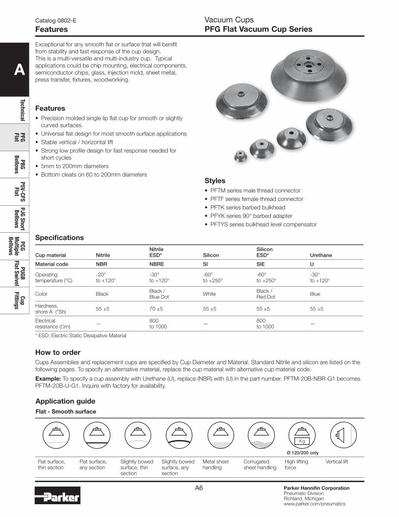
FeaturesVacuum CupsPFG Flat Vacuum Cup Series
Features• Precision molded single lip flat cup for smooth or slightly
curved surfaces. • Universal flat design for most smooth surface applications• Stable vertical / horizontal lift• Strong low profile design for fast response needed for
short cycles• 5mm to 200mm diameters• Bottom cleats on 60 to 200mm diameters
Exceptional for any smooth flat or surface that will benifit from stability and fast response of the cup design. This is a multi-versatile and multi-industry cup. Typical applications could be chip mounting, electrical components, semiconductor chips, glass, injection mold, sheet metal, press transfer, fixtures, woodworking.
Specifications
Cup material NitrileNitrileESD* Silicon
SiliconESD* Urethane
Material code NBR NBRE SI SIE U
Operating temperature (°C)
-20° to +120°
-30° to +120°
-60° to +250°
-60° to +250°
-30° to +120°
Color Black Black / Blue Dot White Black /
Red Dot Blue
Hardness, shore A (°Sh) 55 ±5 70 ±5 55 ±5 55 ±5 55 ±5
Electrical resistance (Ωm) — 800
to 1000 — 800 to 1000 —
* ESD: Electric Static Dissipative Material
Styles• PFTM series male thread connector• PFTF series female thread connector• PFTK series barbed bulkhead• PFYK series 90° barbed adapter• PFTYS series bulkhead level compensator
How to orderCups Assemblies and replacement cups are specified by Cup Diameter and Material. Standard Nitrile and silicon are listed on the following pages. To specify an alternative material, replace the cup material with alternative cup material code.
Example: To specify a cup assembly with Urethane (U), replace (NBR) with (U) in the part number. PFTM-20B-NBR-G1 becomes PFTM-20B-U-G1. Inquire with factory for availability.
Application guideFlat - Smooth surface
Ø 120/200 only
Flat surface, thin section
Flat surface, any section
Slightly bowed surface, thin section
Slightly bowed surface, any section
Metal sheet handling
Corrugated sheet handling
High lifting force
Vertical lift
A
Tech
nica
lPF
G Fl
atPB
G Be
llow
sP5
V-CF
S Fl
atPJ
G Sh
ort
Bello
ws
PCG
Mul
tiple
Be
llow
s
PUGB
Fl
at S
wiv
elCu
p Fi
tting
s
Parker Hannifin CorporationPneumatic DivisionRichland, Michiganwww.parker.com/pneumatics
A7
Catalog 0802-E
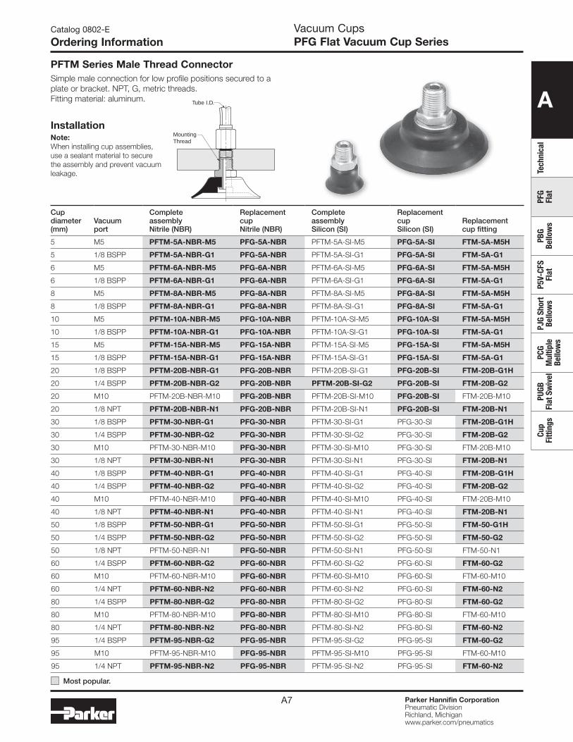
Ordering InformationVacuum CupsPFG Flat Vacuum Cup Series
Tube I.D.
MountingThread
InstallationNote:When installing cup assemblies, use a sealant material to secure the assembly and prevent vacuum leakage.
PFTM Series Male Thread ConnectorSimple male connection for low profile positions secured to a plate or bracket. NPT, G, metric threads. Fitting material: aluminum.
Cup diameter (mm)
Vacuumport
Complete assembly Nitrile (NBR)
Replacement cup Nitrile (NBR)
Complete assemblySilicon (SI)
Replacement cupSilicon (SI)
Replacement cup fitting
5 M5 PFTM-5A-NBR-M5 PFG-5A-NBR PFTM-5A-SI-M5 PFG-5A-SI FTM-5A-M5H
5 1/8 BSPP PFTM-5A-NBR-G1 PFG-5A-NBR PFTM-5A-SI-G1 PFG-5A-SI FTM-5A-G1
6 M5 PFTM-6A-NBR-M5 PFG-6A-NBR PFTM-6A-SI-M5 PFG-6A-SI FTM-5A-M5H
6 1/8 BSPP PFTM-6A-NBR-G1 PFG-6A-NBR PFTM-6A-SI-G1 PFG-6A-SI FTM-5A-G1
8 M5 PFTM-8A-NBR-M5 PFG-8A-NBR PFTM-8A-SI-M5 PFG-8A-SI FTM-5A-M5H
8 1/8 BSPP PFTM-8A-NBR-G1 PFG-8A-NBR PFTM-8A-SI-G1 PFG-8A-SI FTM-5A-G1
10 M5 PFTM-10A-NBR-M5 PFG-10A-NBR PFTM-10A-SI-M5 PFG-10A-SI FTM-5A-M5H
10 1/8 BSPP PFTM-10A-NBR-G1 PFG-10A-NBR PFTM-10A-SI-G1 PFG-10A-SI FTM-5A-G1
15 M5 PFTM-15A-NBR-M5 PFG-15A-NBR PFTM-15A-SI-M5 PFG-15A-SI FTM-5A-M5H
15 1/8 BSPP PFTM-15A-NBR-G1 PFG-15A-NBR PFTM-15A-SI-G1 PFG-15A-SI FTM-5A-G1
20 1/8 BSPP PFTM-20B-NBR-G1 PFG-20B-NBR PFTM-20B-SI-G1 PFG-20B-SI FTM-20B-G1H
20 1/4 BSPP PFTM-20B-NBR-G2 PFG-20B-NBR PFTM-20B-SI-G2 PFG-20B-SI FTM-20B-G2
20 M10 PFTM-20B-NBR-M10 PFG-20B-NBR PFTM-20B-SI-M10 PFG-20B-SI FTM-20B-M10
20 1/8 NPT PFTM-20B-NBR-N1 PFG-20B-NBR PFTM-20B-SI-N1 PFG-20B-SI FTM-20B-N1
30 1/8 BSPP PFTM-30-NBR-G1 PFG-30-NBR PFTM-30-SI-G1 PFG-30-SI FTM-20B-G1H
30 1/4 BSPP PFTM-30-NBR-G2 PFG-30-NBR PFTM-30-SI-G2 PFG-30-SI FTM-20B-G2
30 M10 PFTM-30-NBR-M10 PFG-30-NBR PFTM-30-SI-M10 PFG-30-SI FTM-20B-M10
30 1/8 NPT PFTM-30-NBR-N1 PFG-30-NBR PFTM-30-SI-N1 PFG-30-SI FTM-20B-N1
40 1/8 BSPP PFTM-40-NBR-G1 PFG-40-NBR PFTM-40-SI-G1 PFG-40-SI FTM-20B-G1H
40 1/4 BSPP PFTM-40-NBR-G2 PFG-40-NBR PFTM-40-SI-G2 PFG-40-SI FTM-20B-G2
40 M10 PFTM-40-NBR-M10 PFG-40-NBR PFTM-40-SI-M10 PFG-40-SI FTM-20B-M10
40 1/8 NPT PFTM-40-NBR-N1 PFG-40-NBR PFTM-40-SI-N1 PFG-40-SI FTM-20B-N1
50 1/8 BSPP PFTM-50-NBR-G1 PFG-50-NBR PFTM-50-SI-G1 PFG-50-SI FTM-50-G1H
50 1/4 BSPP PFTM-50-NBR-G2 PFG-50-NBR PFTM-50-SI-G2 PFG-50-SI FTM-50-G2
50 1/8 NPT PFTM-50-NBR-N1 PFG-50-NBR PFTM-50-SI-N1 PFG-50-SI FTM-50-N1
60 1/4 BSPP PFTM-60-NBR-G2 PFG-60-NBR PFTM-60-SI-G2 PFG-60-SI FTM-60-G2
60 M10 PFTM-60-NBR-M10 PFG-60-NBR PFTM-60-SI-M10 PFG-60-SI FTM-60-M10
60 1/4 NPT PFTM-60-NBR-N2 PFG-60-NBR PFTM-60-SI-N2 PFG-60-SI FTM-60-N2
80 1/4 BSPP PFTM-80-NBR-G2 PFG-80-NBR PFTM-80-SI-G2 PFG-80-SI FTM-60-G2
80 M10 PFTM-80-NBR-M10 PFG-80-NBR PFTM-80-SI-M10 PFG-80-SI FTM-60-M10
80 1/4 NPT PFTM-80-NBR-N2 PFG-80-NBR PFTM-80-SI-N2 PFG-80-SI FTM-60-N2
95 1/4 BSPP PFTM-95-NBR-G2 PFG-95-NBR PFTM-95-SI-G2 PFG-95-SI FTM-60-G2
95 M10 PFTM-95-NBR-M10 PFG-95-NBR PFTM-95-SI-M10 PFG-95-SI FTM-60-M10
95 1/4 NPT PFTM-95-NBR-N2 PFG-95-NBR PFTM-95-SI-N2 PFG-95-SI FTM-60-N2
Most popular.
A
TechnicalPFG Flat
PBG Bellow
sP5V-CFS
FlatPJG Short Bellow
sPCG
Multiple
Bellows
PUGB Flat Sw
ivelCup
Fittings
Parker Hannifin CorporationPneumatic DivisionRichland, Michiganwww.parker.com/pneumatics
A8
Catalog 0802-E
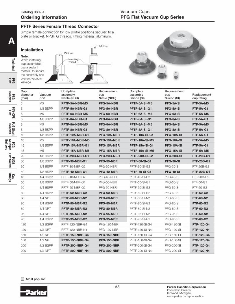
Ordering InformationVacuum CupsPFG Flat Vacuum Cup Series
PFTF Series Female Thread ConnectorSimple female connection for low profile positions secured to a plate or bracket. NPSF, G threads. Fitting material: aluminum.
Tube I.D.
Pipe I.D.
MountingThread
InstallationNote:When installing cup assemblies, use a sealant material to secure the assembly and prevent vacuum leakage.
Cup diameter (mm)
Vacuumport
Complete assembly Nitrile (NBR)
Replacement cup Nitrile (NBR)
Complete assemblySilicon (SI)
Replacement cupSilicon (SI)
Replacement cup fitting
5 M5 PFTF-5A-NBR-M5 PFG-5A-NBR PFTF-5A-SI-M5 PFG-5A-SI FTF-5A-M5
5 1/8 BSPP PFTF-5A-NBR-G1 PFG-5A-NBR PFTF-5A-SI-G1 PFG-5A-SI FTF-5A-G1
6 M5 PFTF-6A-NBR-M5 PFG-6A-NBR PFTF-6A-SI-M5 PFG-6A-SI FTF-5A-M5
6 1/8 BSPP PFTF-6A-NBR-G1 PFG-6A-NBR PFTF-6A-SI-G1 PFG-6A-SI FTF-5A-G1
8 M5 PFTF-8A-NBR-M5 PFG-8A-NBR PFTF-8A-SI-M5 PFG-8A-SI FTF-5A-M5
8 1/8 BSPP PFTF-8A-NBR-G1 PFG-8A-NBR PFTF-8A-SI-G1 PFG-8A-SI FTF-5A-G1
10 1/8 BSPP PFTF-10A-NBR-G1 PFG-10A-NBR PFTF-10A-SI-G1 PFG-10A-SI FTF-5A-G1
10 M5 PFTF-10A-NBR-M5 PFG-10A-NBR PFTF-10A-SI-M5 PFG-10A-SI FTF-5A-M5
15 1/8 BSPP PFTF-15A-NBR-G1 PFG-15A-NBR PFTF-15A-SI-G1 PFG-15A-SI FTF-5A-G1
15 M5 PFTF-15A-NBR-M5 PFG-15A-NBR PFTF-15A-SI-M5 PFG-15A-SI FTF-5A-M5
20 1/8 BSPP PFTF-20B-NBR-G1 PFG-20B-NBR PFTF-20B-SI-G1 PFG-20B-SI FTF-20B-G1
30 1/8 BSPP PFTF-30-NBR-G1 PFG-30-NBR PFTF-30-SI-G1 PFG-30-SI FTF-20B-G1
30 1/4 BSPP PFTF-30-NBR-G2 PFG-30-NBR PFTF-30-SI-G2 PFG-30-SI FTF-20B-G2
40 1/8 BSPP PFTF-40-NBR-G1 PFG-40-NBR PFTF-40-SI-G1 PFG-40-SI FTF-20B-G1
40 1/4 BSPP PFTF-40-NBR-G2 PFG-40-NBR PFTF-40-SI-G2 PFG-40-SI FTF-20B-G2
50 1/8 BSPP PFTF-50-NBR-G1 PFG-50-NBR PFTF-50-SI-G1 PFG-50-SI FTF-50-G1
50 1/4 BSPP PFTF-50-NBR-G2 PFG-50-NBR PFTF-50-SI-G2 PFG-50-SI FTF-50-G2
60 1/4 BSPP PFTF-60-NBR-G2 PFG-60-NBR PFTF-60-SI-G2 PFG-60-SI FTF-60-G2
60 1/4 NPT PFTF-60-NBR-N2 PFG-60-NBR PFTF-60-SI-N2 PFG-60-SI FTF-60-N2
80 1/4 BSPP PFTF-80-NBR-G2 PFG-80-NBR PFTF-80-SI-G2 PFG-80-SI FTF-60-G2
80 1/4 NPT PFTF-80-NBR-N2 PFG-80-NBR PFTF-80-SI-N2 PFG-80-SI FTF-60-N2
95 1/4 NPT PFTF-95-NBR-N2 PFG-95-NBR PFTF-95-SI-N2 PFG-95-SI FTF-60-N2
95 1/4 BSPP PFTF-95-NBR-G2 PFG-95-NBR PFTF-95-SI-G2 PFG-95-SI FTF-60-G2
120 1/2 BSPP PFTF-120-NBR-G4 PFG-120-NBR PFTF-120-SI-G4 PFG-120-SI FTF-120-G4
120 1/2 NPT PFTF-120-NBR-N4 PFG-120-NBR PFTF-120-SI-N4 PFG-120-SI FTF-120-N4
150 1/2 NPT PFTF-150-NBR-G4 PFG-150-NBR PFTF-150-SI-G4 PFG-150-SI FTF-120-G4
150 1/2 NPT PFTF-150-NBR-N4 PFG-150-NBR PFTF-150-SI-N4 PFG-150-SI FTF-120-N4
200 1/2 BSPP PFTF-200-NBR-G4 PFG-200-NBR PFTF-200-SI-G4 PFG-200-SI FTF-120-G4
200 1/2 NPT PFTF-200-NBR-N4 PFG-200-NBR PFTF-200-SI-N4 PFG-200-SI FTF-120-N4
Most popular.
A
Tech
nica
lPF
G Fl
atPB
G Be
llow
sP5
V-CF
S Fl
atPJ
G Sh
ort
Bello
ws
PCG
Mul
tiple
Be
llow
s
PUGB
Fl
at S
wiv
elCu
p Fi
tting
s
Parker Hannifin CorporationPneumatic DivisionRichland, Michiganwww.parker.com/pneumatics
A9
Catalog 0802-E
Ordering InformationVacuum CupsPFG Flat Vacuum Cup Series
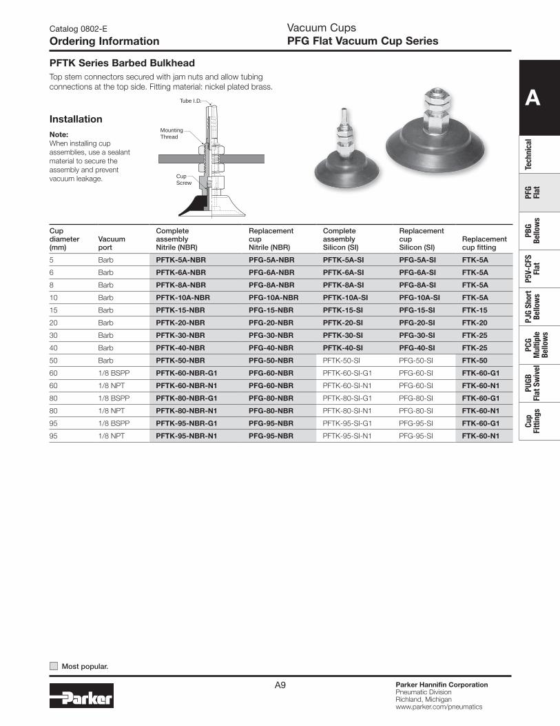
PFTK Series Barbed BulkheadTop stem connectors secured with jam nuts and allow tubing connections at the top side. Fitting material: nickel plated brass.
Tube I.D.
MountingThread
CupScrew
InstallationNote:When installing cup assemblies, use a sealant material to secure the assembly and prevent vacuum leakage.
Cup diameter (mm)
Vacuumport
Complete assembly Nitrile (NBR)
Replacement cup Nitrile (NBR)
Complete assemblySilicon (SI)
Replacement cupSilicon (SI)
Replacement cup fitting
5 Barb PFTK-5A-NBR PFG-5A-NBR PFTK-5A-SI PFG-5A-SI FTK-5A
6 Barb PFTK-6A-NBR PFG-6A-NBR PFTK-6A-SI PFG-6A-SI FTK-5A
8 Barb PFTK-8A-NBR PFG-8A-NBR PFTK-8A-SI PFG-8A-SI FTK-5A
10 Barb PFTK-10A-NBR PFG-10A-NBR PFTK-10A-SI PFG-10A-SI FTK-5A
15 Barb PFTK-15-NBR PFG-15-NBR PFTK-15-SI PFG-15-SI FTK-15
20 Barb PFTK-20-NBR PFG-20-NBR PFTK-20-SI PFG-20-SI FTK-20
30 Barb PFTK-30-NBR PFG-30-NBR PFTK-30-SI PFG-30-SI FTK-25
40 Barb PFTK-40-NBR PFG-40-NBR PFTK-40-SI PFG-40-SI FTK-25
50 Barb PFTK-50-NBR PFG-50-NBR PFTK-50-SI PFG-50-SI FTK-50
60 1/8 BSPP PFTK-60-NBR-G1 PFG-60-NBR PFTK-60-SI-G1 PFG-60-SI FTK-60-G1
60 1/8 NPT PFTK-60-NBR-N1 PFG-60-NBR PFTK-60-SI-N1 PFG-60-SI FTK-60-N1
80 1/8 BSPP PFTK-80-NBR-G1 PFG-80-NBR PFTK-80-SI-G1 PFG-80-SI FTK-60-G1
80 1/8 NPT PFTK-80-NBR-N1 PFG-80-NBR PFTK-80-SI-N1 PFG-80-SI FTK-60-N1
95 1/8 BSPP PFTK-95-NBR-G1 PFG-95-NBR PFTK-95-SI-G1 PFG-95-SI FTK-60-G1
95 1/8 NPT PFTK-95-NBR-N1 PFG-95-NBR PFTK-95-SI-N1 PFG-95-SI FTK-60-N1
Most popular.
A
TechnicalPFG Flat
PBG Bellow
sP5V-CFS
FlatPJG Short Bellow
sPCG
Multiple
Bellows
PUGB Flat Sw
ivelCup
Fittings
Parker Hannifin CorporationPneumatic DivisionRichland, Michiganwww.parker.com/pneumatics
A10
Catalog 0802-E
Ordering InformationVacuum CupsPFG Flat Vacuum Cup Series
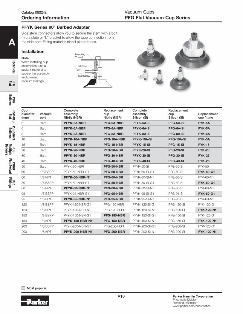
PFYK Series 90° Barbed AdapterSide stem connectors allow you to secure the stem with a bolt thru a plate or “L” bracket to allow the tube connection from the side port. Fitting material: nickel plated brass.
Tube I.D.
MountingThread
Cup Screw
InstallationNote:When installing cup assemblies, use a sealant material to secure the assembly and prevent vacuum leakage.
Cup diameter (mm)
Vacuumport
Complete assembly Nitrile (NBR)
Replacement cup Nitrile (NBR)
Complete assemblySilicon (SI)
Replacement cupSilicon (SI)
Replacement cup fitting
5 Barb PFYK-5A-NBR PFG-5A-NBR PFYK-5A-SI PFG-5A-SI FYK-5A
6 Barb PFYK-6A-NBR PFG-6A-NBR PFYK-6A-SI PFG-6A-SI FYK-5A
8 Barb PFYK-8A-NBR PFG-8A-NBR PFYK-8A-SI PFG-8A-SI FYK-5A
10 Barb PFYK-10A-NBR PFG-10A-NBR PFYK-10A-SI PFG-10A-SI FYK-5A
15 Barb PFYK-15-NBR PFG-15-NBR PFYK-15-SI PFG-15-SI FYK-15
20 Barb PFYK-20-NBR PFG-20-NBR PFYK-20-SI PFG-20-SI FYK-20
30 Barb PFYK-30-NBR PFG-30-NBR PFYK-30-SI PFG-30-SI FYK-25
40 Barb PFYK-40-NBR PFG-40-NBR PFYK-40-SI PFG-40-SI FYK-25
50 Barb PFYK-50-NBR PFG-50-NBR PFYK-50-SI PFG-50-SI FYK-50
60 1/8 BSPP PFYK-60-NBR-G1 PFG-60-NBR PFYK-60-SI-G1 PFG-60-SI FYK-60-G1
60 1/8 NPT PFYK-60-NBR-N1 PFG-60-NBR PFYK-60-SI-N1 PFG-60-SI FYK-60-N1
80 1/8 BSPP PFYK-80-NBR-G1 PFG-80-NBR PFYK-80-SI-G1 PFG-80-SI FYK-60-G1
80 1/8 NPT PFYK-80-NBR-N1 PFG-80-NBR PFYK-80-SI-N1 PFG-80-SI FYK-60-N1
95 1/8 BSPP PFYK-95-NBR-G1 PFG-95-NBR PFYK-95-SI-G1 PFG-95-SI FYK-60-G1
95 1/8 NPT PFYK-95-NBR-N1 PFG-95-NBR PFYK-95-SI-N1 PFG-95-SI FYK-60-N1
120 1/8 BSPP PFYK-120-NBR-G1 PFG-120-NBR PFYK-120-SI-G1 PFG-120-SI FYK-120-G1
120 1/8 NPT PFYK-120-NBR-N1 PFG-120-NBR PFYK-120-SI-N1 PFG-120-SI FYK-120-N1
150 1/8 BSPP PFYK-150-NBR-G1 PFG-150-NBR PFYK-150-SI-G1 PFG-150-SI FYK-120-G1
150 1/8 NPT PFYK-150-NBR-N1 PFG-150-NBR PFYK-150-SI-N1 PFG-150-SI FYK-120-N1
200 1/8 BSPP PFYK-200-NBR-G1 PFG-200-NBR PFYK-200-SI-G1 PFG-200-SI FYK-120-G1
200 1/8 NPT PFYK-200-NBR-N1 PFG-200-NBR PFYK-200-SI-N1 PFG-200-SI FYK-120-N1
Most popular.

A
Tech
nica
lPF
G Fl
atPB
G Be
llow
sP5
V-CF
S Fl
atPJ
G Sh
ort
Bello
ws
PCG
Mul
tiple
Be
llow
s
PUGB
Fl
at S
wiv
elCu
p Fi
tting
s
Parker Hannifin CorporationPneumatic DivisionRichland, Michiganwww.parker.com/pneumatics
A11
Catalog 0802-E
Ordering InformationVacuum CupsPFG Flat Vacuum Cup Series
PFTYS Series Bulkhead Level Compensator303 stainless steel construction secured with jam nuts. Spring biased compensators can absorb impacts of down-strokes and adjust for different levels of pick up points. 303 stainless corrosion resistant materials with drymet bushings increases the strength and life.
PlugPushlockTube Fitting
Barb Fitting
MountingThread
Inte
rcha
ngab
le*
* Not included with assembly
InstallationNote:When installing cup assemblies, use a sealant material to secure the assembly and prevent vacuum leakage.
Cup dia. (mm)
Vacuumport
Stroke (mm)
Spring compression Force lbf (N)0% 100%
Cup material Nitrile assembly (NBR)
Replacement cup Nitrile (NBR)
Cup material Silicon assembly (SI)
Replacement cup Silicon (SI)
Level Compensator P/N
5 M5 10 .14 (.61) .26 (1.17) PFTYS5A10NBRM5 PFG-5A-NBR PFTYS5A10SIM5 PFG-5A-SI TYS-5A-10
5 M5 15 .15 (.64) .26 (1.17) PFTYS5A15NBRM5 PFG-5A-NBR PFTYS5A15SIM5 PFG-5A-SI TYS-5A-15
6 M5 10 .14 (.61) .26 (1.17) PFTYS6A10NBRM5 PFG-6A-NBR PFTYS6A10SIM5 PFG-6A-SI TYS-5A-10
6 M5 15 .15 (.64) .26 (1.17) PFTYS6A15NBRM5 PFG-6A-NBR PFTYS6A15SIM5 PFG-6A-SI TYS-5A-15
8 M5 10 .14 (.61) .26 (1.17) PFTYS8A10NBRM5 PFG-8A-NBR PFTYS8A10SIM5 PFG-8A-SI TYS-5A-10
8 M5 15 .15 (.64) .26 (1.17) PFTYS8A15NBRM5 PFG-8A-NBR PFTYS8A15SIM5 PFG-8A-SI TYS-5A-15
10 M5 10 .11 (.49) .13 (.59) PFTYS10A10NBRM5 PFG-10A-NBR PFTYS10A10SIM5 PFG-10A-SI TYS-5A-10
10 M5 15 .11 (.49) .13 (.59) PFTYS10A15NBRM5 PFG-10A-NBR PFTYS10A15SIM5 PFG-10A-SI TYS-5A-15
15 M5 10 .11 (.49) .13 (.59) PFTYS15A10NBRM5 PFG-15A-NBR PFTYS15A10SIM5 PFG-15A-SI TYS-5A-10
15 M5 15 .11 (.49) .13 (.59) PFTYS15A15NBRM5 PFG-15A-NBR PFTYS15A15SIM5 PFG-15A-SI TYS-5A-15
20 M5 15 .56 (2.5) .79 (3.4) PFTYS20B15NBRM5 PFG-20B-NBR PFTYS20B15SIM5 PFG-20B-SI TYS-20B-15
20 M5 30 .56 (2.5) 1.2 (4.9) PFTYS20B30NBRM5 PFG-20B-NBR PFTYS20B30SIM5 PFG-20B-SI TYS-20B-30
30 M5 15 .56 (2.5) .79 (3.4) PFTYS3015NBRM5 PFG-30-NBR PFTYS3015SIM5 PFG-30-SI TYS-20B-15
30 M5 30 .56 (2.5) 1.2 (4.9) PFTYS3030NBRM5 PFG-30-NBR PFTYS3030SIM5 PFG-30-SI TYS-20B-30
40 M5 15 .56 (2.5) .79 (3.4) PFTYS4015NBRM5 PFG-40-NBR PFTYS4015SIM5 PFG-40-SI TYS-20B-15
40 M5 30 .56 (2.5) 1.2 (4.9) PFTYS4030NBRM5 PFG-40-NBR PFTYS4030SIM5 PFG-40-SI TYS-20B-30
50 M5 15 .56 (2.5) 1.2 (4.9) PFTYS5015NBRM5 PFG-50-NBR PFTYS5015SIM5 PFG-50-SI TYS-50-15
50 M5 30 .67 (2.9) 1.4 (5.9) PFTYS5030NBRM5 PFG-50-NBR PFTYS5030SIM5 PFG-50-SI TYS-50-30
60 1/8 NPT 30 1.6 (6.8) 3.6 (15.6) PFTYS6030NBRN1 PFG-60-NBR PFTYS6030SIN1 PFG-60-SI TYS-60-30
60 1/8 NPT 50 1.9 (8.3) 4.5 (19.6) PFTYS6050NBRN1 PFG-60-NBR PFTYS6050SIN1 PFG-60-SI TYS-60-50
80 1/8 NPT 30 1.6 (6.8) 3.6 (15.6) PFTYS8030NBRN1 PFG-80-NBR PFTYS8030SIN1 PFG-80-SI TYS-60-30
80 1/8 NPT 50 1.9 (8.3) 4.5 (19.6) PFTYS8050NBRN1 PFG-80-NBR PFTYS8050SIN1 PFG-80-SI TYS-60-50
95 1/8 NPT 30 1.6 (6.8) 3.6 (15.6) PFTYS9530NBRN1 PFG-95-NBR PFTYS9530SIN1 PFG-95-SI TYS-60-30
95 1/8 NPT 50 1.9 (8.3) 4.5 (19.6) PFTYS9550NBRN1 PFG-95-NBR PFTYS9550SIN1 PFG-95-SI TYS-60-50
120 1/4 NPT 20 3.6 (15.6) 6.8 (29) PFTYS12020NBRN2 PFG-120-NBR PFTYS12020SIN2 PFG-120-SI TYS-120-20
120 1/4 NPT 70 3.4 (14.7) 6.8 (29) PFTYS12070NBRN2 PFG-120-NBR PFTYS12070SIN2 PFG-120-SI TYS-120-70
150 1/4 NPT 20 3.6 (15.6) 6.8 (29) PFTYS15020NBRN2 PFG-150-NBR PFTYS15020SIN2 PFG-150-SI TYS-120-20
150 1/4 NPT 70 3.4 (14.7) 6.8 (29) PFTYS15070NBRN2 PFG-150-NBR PFTYS15070SIN2 PFG-150-SI TYS-120-70
200 1/4 NPT 20 3.6 (15.6) 6.8 (29) PFTYS20020NBRN2 PFG-200-NBR PFTYS20020SIN2 PFG-200-SI TYS-120-20
200 1/4 NPT 70 3.4 (14.7) 6.8 (29) PFTYS20070NBRN2 PFG-200-NBR PFTYS20070SIN2 PFG-200-SI TYS-120-70
Most popular.
A
TechnicalPFG Flat
PBG Bellow
sP5V-CFS
FlatPJG Short Bellow
sPCG
Multiple
Bellows
PUGB Flat Sw
ivelCup
Fittings
Parker Hannifin CorporationPneumatic DivisionRichland, Michiganwww.parker.com/pneumatics
A12
Vacuum CupsPFG Flat Vacuum Cup Series
Catalog 0802-E
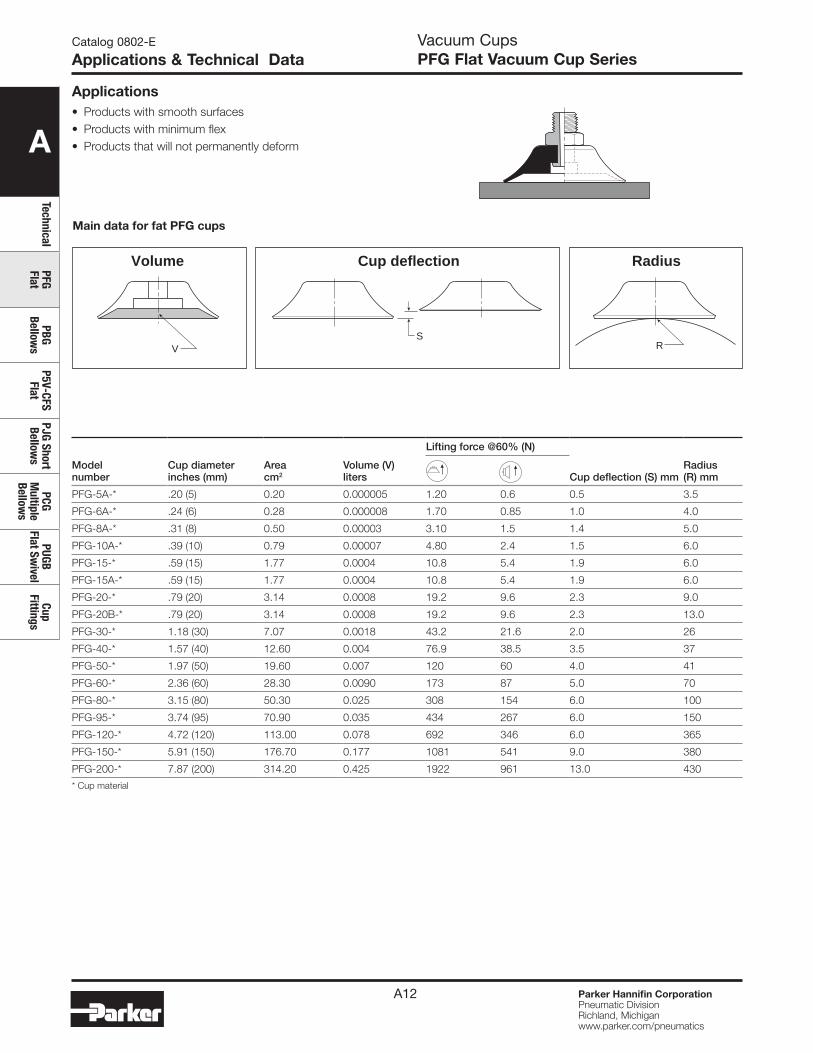
Applications & Technical Data
SRV
Volume RadiusCup deflection
Model number
Cup diameter inches (mm)
Area cm2
Volume (V) liters
Lifting force @60% (N)
Cup deflection (S) mmRadius (R) mm
PFG-5A-* .20 (5) 0.20 0.000005 1.20 0.6 0.5 3.5
PFG-6A-* .24 (6) 0.28 0.000008 1.70 0.85 1.0 4.0
PFG-8A-* .31 (8) 0.50 0.00003 3.10 1.5 1.4 5.0
PFG-10A-* .39 (10) 0.79 0.00007 4.80 2.4 1.5 6.0
PFG-15-* .59 (15) 1.77 0.0004 10.8 5.4 1.9 6.0
PFG-15A-* .59 (15) 1.77 0.0004 10.8 5.4 1.9 6.0
PFG-20-* .79 (20) 3.14 0.0008 19.2 9.6 2.3 9.0
PFG-20B-* .79 (20) 3.14 0.0008 19.2 9.6 2.3 13.0
PFG-30-* 1.18 (30) 7.07 0.0018 43.2 21.6 2.0 26
PFG-40-* 1.57 (40) 12.60 0.004 76.9 38.5 3.5 37
PFG-50-* 1.97 (50) 19.60 0.007 120 60 4.0 41
PFG-60-* 2.36 (60) 28.30 0.0090 173 87 5.0 70
PFG-80-* 3.15 (80) 50.30 0.025 308 154 6.0 100
PFG-95-* 3.74 (95) 70.90 0.035 434 267 6.0 150
PFG-120-* 4.72 (120) 113.00 0.078 692 346 6.0 365
PFG-150-* 5.91 (150) 176.70 0.177 1081 541 9.0 380
PFG-200-* 7.87 (200) 314.20 0.425 1922 961 13.0 430
* Cup material
Main data for fat PFG cups
• Products with smooth surfaces• Products with minimum flex• Products that will not permanently deform
Applications
A
Tech
nica
lPF
G Fl
atPB
G Be
llow
sP5
V-CF
S Fl
atPJ
G Sh
ort
Bello
ws
PCG
Mul
tiple
Be
llow
s
PUGB
Fl
at S
wiv
elCu
p Fi
tting
s
Parker Hannifin CorporationPneumatic DivisionRichland, Michiganwww.parker.com/pneumatics
A13
FA
DJB
C
EGH
PFG-5APFG-15A
PFG-60 thruPFG-95
PFG-120 thruPFG-200
H
AC
BD
F
E
H
AC
B
D
F
E
A
E
H
F
B
D
A
BD
4 Bolt Pattern 40mm Dia.
G Dia.Typ. 4 Places
C
E
H
F
PFG-15 thruPFG-40
Catalog 0802-E
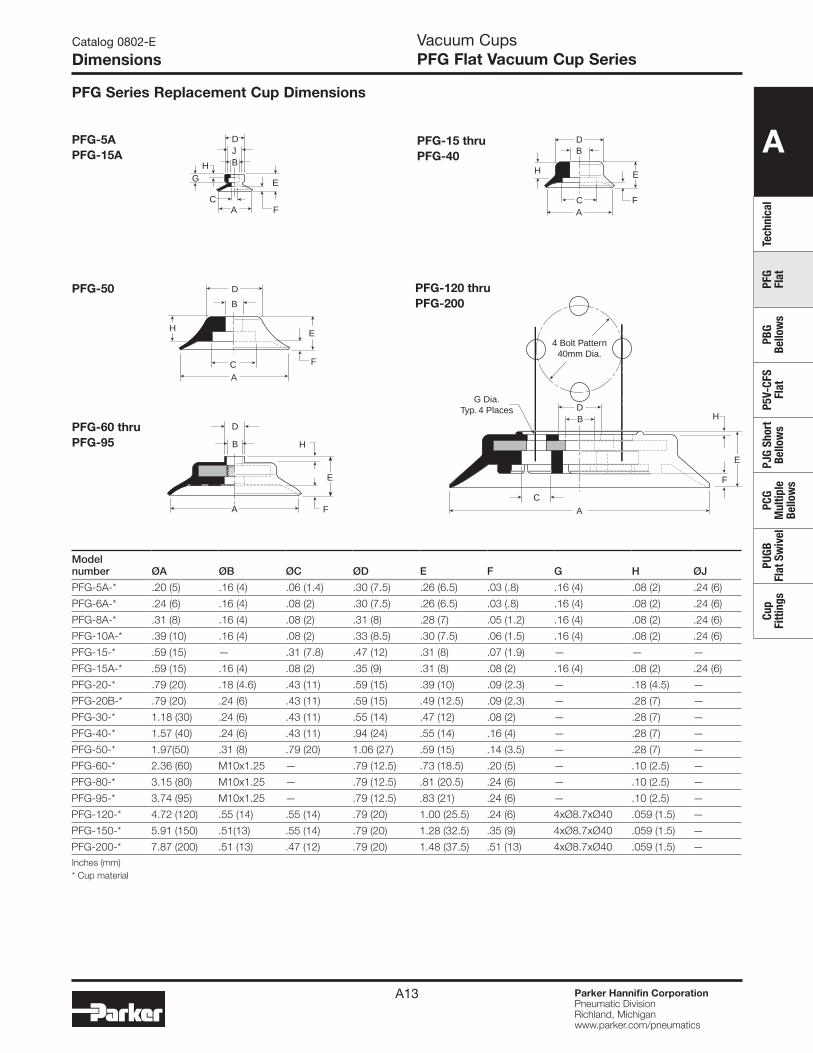
DimensionsVacuum CupsPFG Flat Vacuum Cup Series
PFG Series Replacement Cup Dimensions
PFG-50
Model number ØA ØB ØC ØD E F G H ØJ
PFG-5A-* .20 (5) .16 (4) .06 (1.4) .30 (7.5) .26 (6.5) .03 (.8) .16 (4) .08 (2) .24 (6)
PFG-6A-* .24 (6) .16 (4) .08 (2) .30 (7.5) .26 (6.5) .03 (.8) .16 (4) .08 (2) .24 (6)
PFG-8A-* .31 (8) .16 (4) .08 (2) .31 (8) .28 (7) .05 (1.2) .16 (4) .08 (2) .24 (6)
PFG-10A-* .39 (10) .16 (4) .08 (2) .33 (8.5) .30 (7.5) .06 (1.5) .16 (4) .08 (2) .24 (6)
PFG-15-* .59 (15) — .31 (7.8) .47 (12) .31 (8) .07 (1.9) — — —
PFG-15A-* .59 (15) .16 (4) .08 (2) .35 (9) .31 (8) .08 (2) .16 (4) .08 (2) .24 (6)
PFG-20-* .79 (20) .18 (4.6) .43 (11) .59 (15) .39 (10) .09 (2.3) — .18 (4.5) —
PFG-20B-* .79 (20) .24 (6) .43 (11) .59 (15) .49 (12.5) .09 (2.3) — .28 (7) —
PFG-30-* 1.18 (30) .24 (6) .43 (11) .55 (14) .47 (12) .08 (2) — .28 (7) —
PFG-40-* 1.57 (40) .24 (6) .43 (11) .94 (24) .55 (14) .16 (4) — .28 (7) —
PFG-50-* 1.97(50) .31 (8) .79 (20) 1.06 (27) .59 (15) .14 (3.5) — .28 (7) —
PFG-60-* 2.36 (60) M10x1.25 — .79 (12.5) .73 (18.5) .20 (5) — .10 (2.5) —
PFG-80-* 3.15 (80) M10x1.25 — .79 (12.5) .81 (20.5) .24 (6) — .10 (2.5) —
PFG-95-* 3.74 (95) M10x1.25 — .79 (12.5) .83 (21) .24 (6) — .10 (2.5) —
PFG-120-* 4.72 (120) .55 (14) .55 (14) .79 (20) 1.00 (25.5) .24 (6) 4xØ8.7xØ40 .059 (1.5) —
PFG-150-* 5.91 (150) .51(13) .55 (14) .79 (20) 1.28 (32.5) .35 (9) 4xØ8.7xØ40 .059 (1.5) —
PFG-200-* 7.87 (200) .51 (13) .47 (12) .79 (20) 1.48 (37.5) .51 (13) 4xØ8.7xØ40 .059 (1.5) —Inches (mm)* Cup material

A
TechnicalPFG Flat
PBG Bellow
sP5V-CFS
FlatPJG Short Bellow
sPCG
Multiple
Bellows
PUGB Flat Sw
ivelCup
Fittings
Parker Hannifin CorporationPneumatic DivisionRichland, Michiganwww.parker.com/pneumatics
A14
PFTM-5A thru PFTM-15A
PFTM-20B thru PFTM-50
PFTM-60 thru PFTM-95
Model number ØA B
C (M3)
C (M5)
C (N1 / G1)
C (M10 / G2)
C (N2) D E
PFTM-5A-*-† .20 (5) .39 (10) — .18 (4.5) .31 (8) — — See Dwg. .31 (8)
PFTM-6A-*-† .24 (6) .39 (10) — .18 (4.5) .31 (8) — — See Dwg. .31 (8)
PFTM-8A-*-† .31 (8) .41 (10.5) — .18 (4.5) .31 (8) — — See Dwg. .05 (1.2)
PFTM-10A-*-† .39 (10) .43 (11) — .18 (4.5) .31 (8) — — See Dwg. .06 (1.5)
PFTM-15A-*-† .59 (15) .45 (11.5) — .18 (4.5) .31 (8) — — See Dwg. .08 (2)
PFTM-20B-*-† .79 (20) .69 (17.5) — — .31 (8) .39 (10) — .20 (5) .10 (2.5)
PFTM-30-*-† 1.18 (30) .67 (17) — — .31 (8) .39 (10) — .20 (5) .08 (2)
PFTM-40-*-† 1.57 (40) .75 (19) — — .31 (8) .39 (10) — .20 (5) .14 (3.5)
PFTM-50-*-† 1.97 (50) .79 (20) — — .31 (8) .39 (10) — .20 (5) .16 (4)
PFTM-60-*-† 2.36 (60) .90 (23) — — — .39 (10) .59 (15) .28 (7) .20 (5)
PFTM-80-*-† 3.15 (80) .98 (25) — — — .39 (10) .59 (15) .28 (7) .24 (6)
PFTM-95-*-† 3.74 (95) 1.00 (25.5) — — — .39 (10) .59 (15) .28 (7) .24 (6)
Inches (mm)* Cup material† Thread size
Catalog 0802-E
DimensionsVacuum CupsPFTM Series Assemblies
Dimensions
A
B
C
D
E
N2: 1/4 NPTG2: 1/4 BSPPM10: 10x1.25
9/16"
N1: 1/8 NPTG1: 1/8 BSPPM10: 10x1.25G2: 1/4 BSPP
20B thru 40: 1/2"50: 9/16"
A E
B
C
D
M5: M5G1: 1/8" BSPP(5A thru 15A Only)
M5: SW8G1: SW13(5A thru 15A Only)
M5: .14 (3.5)G1: .20 (5)(5A thru 15A Only) E
B
CD
A
A
Tech
nica
lPF
G Fl
atPB
G Be
llow
sP5
V-CF
S Fl
atPJ
G Sh
ort
Bello
ws
PCG
Mul
tiple
Be
llow
s
PUGB
Fl
at S
wiv
elCu
p Fi
tting
s
Parker Hannifin CorporationPneumatic DivisionRichland, Michiganwww.parker.com/pneumatics
A15
Catalog 0802-E
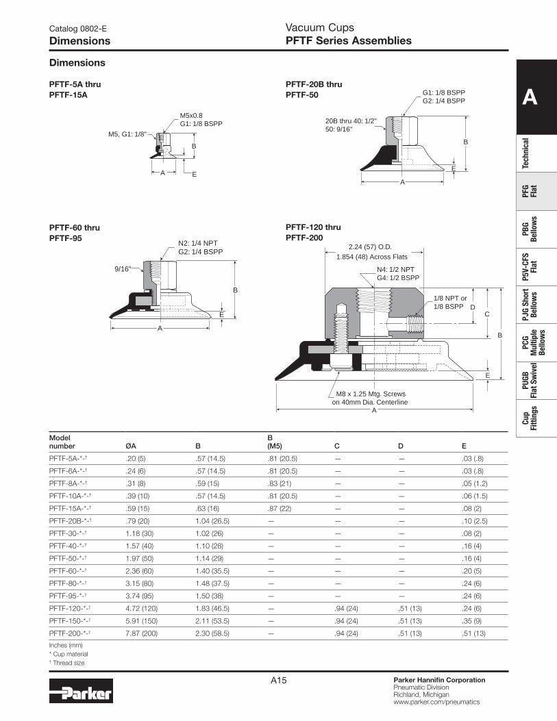
DimensionsVacuum CupsPFTF Series Assemblies
PFTF-5A thru PFTF-15A
PFTF-60 thru PFTF-95
PFTF-120 thru PFTF-200
Model number ØA B
B (M5) C D E
PFTF-5A-*-† .20 (5) .57 (14.5) .81 (20.5) — — .03 (.8)
PFTF-6A-*-† .24 (6) .57 (14.5) .81 (20.5) — — .03 (.8)
PFTF-8A-*-† .31 (8) .59 (15) .83 (21) — — .05 (1.2)
PFTF-10A-*-† .39 (10) .57 (14.5) .81 (20.5) — — .06 (1.5)
PFTF-15A-*-† .59 (15) .63 (16) .87 (22) — — .08 (2)
PFTF-20B-*-† .79 (20) 1.04 (26.5) — — — .10 (2.5)
PFTF-30-*-† 1.18 (30) 1.02 (26) — — — .08 (2)
PFTF-40-*-† 1.57 (40) 1.10 (28) — — — .16 (4)
PFTF-50-*-† 1.97 (50) 1.14 (29) — — — .16 (4)
PFTF-60-*-† 2.36 (60) 1.40 (35.5) — — — .20 (5)
PFTF-80-*-† 3.15 (80) 1.48 (37.5) — — — .24 (6)
PFTF-95-*-† 3.74 (95) 1.50 (38) — — — .24 (6)
PFTF-120-*-† 4.72 (120) 1.83 (46.5) — .94 (24) .51 (13) .24 (6)
PFTF-150-*-† 5.91 (150) 2.11 (53.5) — .94 (24) .51 (13) .35 (9)
PFTF-200-*-† 7.87 (200) 2.30 (58.5) — .94 (24) .51 (13) .51 (13)
Inches (mm)* Cup material† Thread size
A
B
E
N2: 1/4 NPTG2: 1/4 BSPP
9/16"
A
N4: 1/2 NPTG4: 1/2 BSPP
1/8 NPT or1/8 BSPP
B
D
E
C
2.24 (57) O.D.
1.854 (48) Across Flats
M8 x 1.25 Mtg. Screwson 40mm Dia. Centerline
Dimensions
PFTF-20B thru PFTF-50 G1: 1/8 BSPP
G2: 1/4 BSPP
20B thru 40: 1/2"50: 9/16"
A
E
B
EA
B
M5x0.8G1: 1/8 BSPP
M5, G1: 1/8"
A
TechnicalPFG Flat
PBG Bellow
sP5V-CFS
FlatPJG Short Bellow
sPCG
Multiple
Bellows
PUGB Flat Sw
ivelCup
Fittings
Parker Hannifin CorporationPneumatic DivisionRichland, Michiganwww.parker.com/pneumatics
A16
Catalog 0802-E
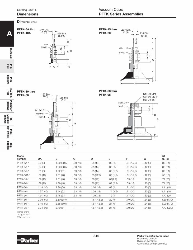
DimensionsVacuum CupsPFTK Series Assemblies
PFTK-5A thru PFTK-10A
PFTK-15 thru PFTK-20
Model number ØA B C D E F G
Wt oz. (g)
PFTK-5A-* .20 (5) 1.20 (30.5) .39 (10) .55 (14) .03 (.8) .61 (15.5) .12 (3) .39 (11)
PFTK-6A-* .24 (6) 1.20 (30.5) .39 (10) .55 (14) .03 (.8) .61 (15.5) .12 (3) .39 (11)
PFTK-8A-* .31 (8) 1.22 (31) .39 (10) .55 (14) .05 (1.2) .61 (15.5) .12 (3) .39 (11)
PFTK-10A-* .39 (10) 1.81 (46) .63 (16) .88 (22.5) .06 (1.5) .61 (15.5) .12 (3) .53 (15)
PFTK-15-* .59 (15) 1.81 (46) .63 (16) .86 (22) .07(1.9) .59 (15) .12 (3) .71 (20)
PFTK-20-* .79 (20) 1.89 (48) .63 (16) .86 (22) .09 (2.3) .59 (15) .20 (5) .71 (20)
PFTK-30-* 1.18 (30) 2.36 (60) .63 (16) 1.26 (32) .08 (2) .71 (20) .20 (5) 1.41 (40)
PFTK-40-* 1.57 (40) 2.44 (62) .63 (16) 1.26 (32) .14 (3.5) .71 (20) .20 (5) 1.41 (40)
PFTK-50-* 1.97 (50) 2.48 (63) .63 (16) 1.26 (32) .16 (4) .71 (20) .20 (5) 1.77 (50)
PFTK-60-*-† 2.36 (60) 2.30 (58.5) — 1.67 (42.5) .20 (5) .79 (20) .24 (6) 4.59 (130)
PFTK-80-*-† 3.15 (80) 2.38 (60.5) — 1.67 (42.5) .24 (6) .79 (20) .24 (6) 6.00 (170)
PFTK-95-*-† 3.74 (95) 2.40 (61) — 1.67 (42.5) .24 (6) .79 (20) .24 (6) 7.77 (220)
Inches (mm) * Cup material † Vacuum port
A
BFG
C
D
E
M8x1.25
SW12
.197 Dia.Ø (5) .118 Dia.
Ø (3)
.197 Dia.Ø (5)
.098 Dia.Ø (2.5)
FG
C
D B
E
M9SW12
A
PFTK-60 thru PFTK-95
A
N1: 1/8 NPTG1: 1/8 BSPPR1: 1/8 BSPT
SW21
M16x1.5
B
FG
D
E
Dimensions
PFTK-30 thru PFTK-50
A
BFG
C
D
E
M10x1.5M5x0.8
SW14
.197 Dia.Ø (5)
.118 Dia.Ø (3)

A
Tech
nica
lPF
G Fl
atPB
G Be
llow
sP5
V-CF
S Fl
atPJ
G Sh
ort
Bello
ws
PCG
Mul
tiple
Be
llow
s
PUGB
Fl
at S
wiv
elCu
p Fi
tting
s
Parker Hannifin CorporationPneumatic DivisionRichland, Michiganwww.parker.com/pneumatics
A17
Catalog 0802-E
DimensionsVacuum CupsPFYK Series Assemblies
PFYK-60 thru PFYK-95
PFYK-120 thru PFYK-200
Model number ØA B C D E F G
Wt oz (g)
PFYK-5A-* .20 (5) 1.14 (29) .51 (13) .89 (22.5) .03 (.8) .24 (6) .63 (16) .56 (16)
PFYK-6A-* .24 (6) 1.14 (29) .51 (13) .89 (22.5) .03 (.8) .24 (6) .63 (16) .56 (16)
PFYK-8A-* .31 (8) 1.16 (29.5) .51 (13) .89 (22.5) .05 (1.2) .24 (6) .63 (16) .56 (16)
PFYK-10A-* .39 (10) 1.18 (30) .51 (13) .89 (22.5) .06 (1.5) .24 (6) .63 (16) .56 (16)
PFYK-15-* .59 (15) 1.18 (30) .55 (14) .87 (22) .07 (1.9) .24 (6) .63 (16) .71 (20)
PFYK-20-* .79 (20) 1.26 (32) .55 (14) .87 (22) .09 (2.3) .24 (6) .63 (16) .71 (20)
PFYK-30-* 1.18 (30) 1.73 (44) .79 (20) 1.26 (32) .08 (2) .31 (8) .63 (16) 1.41 (40)
PFYK-40-* 1.57 (40) 1.81 (46) .79 (20) 1.26 (32) .14 (3.5) .31 (8) .63 (16) 1.77 (50)
PFYK-50-* 1.97 (50) 1.85 (47) .79 (20) 1.26 (32) .16 (4) .31 (8) .63 (16) 1.94 (55)
PFYK-60-*-† 2.36 (60) 2.30 (58.5) 1.10 (28) 1.57 (40) .20 (5) .43 (11) — 4.24 (120)
PFYK-80-*-† 3.15 (80) 2.38 (60.5) 1.10 (28) 1.57 (40) .24 (6) .43 (11) — 5.65 (160)
PFYK-95-*-† 3.74 (95) 2.40 (61) 1.10 (28) 1.57 (40) .24 (6) .43 (11) — 7.42 (210)
PFYK-120-*-† 4.72 (120) 2.94 (75.5) .47 (12) 1.97 (50) .24 (6) .79 (20) 1.18 Dia. (30) 22.6 (640)
PFYK-150-*-† 5.91 (150) 3.25 (82.5) .47 (12) 1.97 (50) .35 (9) .79 (20) 1.18 Dia. (30) 32.1 (910)
PFYK-200-*-† 7.87 (200) 3.44 (87.5) .47 (12) 1.97 (50) .51 (13) .79 (20) 1.18 Dia. (30) 42.4 (1200)
Inches (mm)* Cup material † Vacuum port
PFYK-5A thru PFYK-10A
FC
DB
E.197
Dia
.Ø
(5)
.118
Dia
.Ø
(3)
M4x0.7G
A
PFYK-30 thru PFYK-50
B
F
GM6x1.0
C
D
E
.197
Dia
.Ø
(5)
.118
Dia
.Ø
(3)
AA
M8x1.25
B
F
N1: 1/8 NPTG1: 1/8 BSPP
C
D
E
A
2.75 Dia. (70)(SW65)
GM16
N1: 1/8 NPTG1: 1/8 BSPP B
C
D
E
F
M8 x 1.25 Mtg. Screwson 40mm Dia. Centerline
Dimensions
PFYK-15 thru PFYK-20
B
F
G
A
M4x0.7
C
D
.197
Dia
.Ø
(5)
.118
Dia
.Ø
(3)
E

A
TechnicalPFG Flat
PBG Bellow
sP5V-CFS
FlatPJG Short Bellow
sPCG
Multiple
Bellows
PUGB Flat Sw
ivelCup
Fittings
Parker Hannifin CorporationPneumatic DivisionRichland, Michiganwww.parker.com/pneumatics
A18
Catalog 0802-E
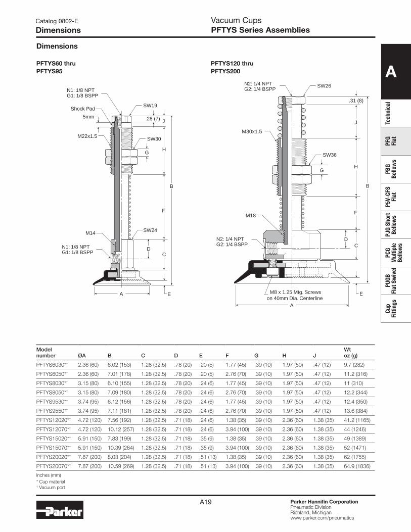
DimensionsVacuum CupsPFTYS Series Assemblies
Model number ØA B C D E F G H
Wt oz (g)
PFTYS5A10*† .20 (5) 2.42 (61.5) .51 (13) .31 (8) .03 (.8) .39 (10) .12 (3) .91 (23) .65 (18.5)
PFTYS5A15*† .20 (5) 2.91 (74) .51 (13) .31 (8) .03 (.8) .59 (15) .12 (3) 1.20 (30.5) .74 (21)
PFTYS6A10*† .24 (6) 2.42 (61.5) .51 (13) .31 (8) .03 (.8) .39 (10) .12 (3) .91 (23) .65 (18.5)
PFTYS6A15*† .24 (6) 2.91 (74) .51 (13) .31 (8) .03 (.8) .59 (15) .12 (3) 1.20 (30.5) .74 (21)
PFTYS8A10*† .31 (8) 2.44 (62) .51 (13) .31 (8) .05 (1.2) .39 (10) .12 (3) .91 (23) .65 (18.5)
PFTYS8A15*† .31 (8) 2.93 (74.5) .51 (13) .31 (8) .05 (1.2) .59 (15) .12 (3) 1.20 (30.5) .74 (21)
PFTYS10A10*† .39 (10) 2.48 (63) .51 (13) .31 (8) .06 (1.5) .39 (10) .12 (3) .91 (23) .65 (18.5)
PFTYS10A15*† .39 (10) 2.95 (75) .51 (13) .31 (8) .06 (1.5) .59 (15) .12 (3) 1.20 (30.5) .74 (21)
PFTYS15A10*† .59 (15) 2.50 (63.5) .51 (13) .31 (8) .08 (2) .39 (10) .12 (3) .91 (23) .65 (18.5)
PFTYS15A15*† .59 (15) 2.97 (75.5) .51 (13) .31 (8) .08 (2) .59 (15) .12 (3) 1.20 (30.5) .74 (21)
PFTYS20B15*† .79 (20) 3.37 (85.5) .67 (17) .39 (10) .09 (2.3) .59 (15) .20 (5) 1.42 (36) 2.5 (71)
PFTYS20B30*† .79 (20) 4.82 (122.5) .67 (17) .39 (10) .09 (2.3) 1.18 (30) .20 (5) 2.28 (58) 3.4 (96)
PFTYS3015*† 1.18 (30) 3.35 (85) .67 (17) .39 (10) .08 (2) .59 (15) .20 (5) 1.42 (36) 2.5 (72)
PFTYS3030*† 1.18 (30) 4.80 (122) .67 (17) .39 (10) .08 (2) 1.18 (30) .20 (5) 2.28 (58 3.5 (97)
PFTYS4015*† 1.57 (40) 3.43 (87) .67 (17) .39 (10) .14 (3.5) .59 (15) .20 (5) 1.42 (36) 2.7 (76)
PFTYS4030*† 1.57 (40) 4.88 (124) .67 (17) .39 (10) .14 (3.5) 1.18 (30) .20 (5) 2.28 (58 3.6 (101)
PFTYS5015*† 1.97 (50) 3.46 (88) .67 (17) .39 (10) .16 (4) .59 (15) .20 (5) 1.42 (36) 3.0 (85)
PFTYS5030*† 1.97 (50) 4.92 (125) .67 (17) .39 (10) .16 (4) 1.18 (30) .20 (5) 2.28 (58) 3.9 (110)
Inches (mm)* Cup material † Vacuum port
M5x0.8
M5x0.8
M5x0.8
SW6
SW12
M8x0.75
B
D C
F
.35 (9)
H
G
EA
PFTYS5A thruPFTYS15A
PFTYS20B thruPFTYS50
M5x0.8 SW12
SW19
SW17
M14x1
M5x0.8
B
D
E
C
H
.20 (5)
F
G
A
M8
Dimensions
A
Tech
nica
lPF
G Fl
atPB
G Be
llow
sP5
V-CF
S Fl
atPJ
G Sh
ort
Bello
ws
PCG
Mul
tiple
Be
llow
s
PUGB
Fl
at S
wiv
elCu
p Fi
tting
s
Parker Hannifin CorporationPneumatic DivisionRichland, Michiganwww.parker.com/pneumatics
A19
Vacuum CupsPFTYS Series Assemblies
Catalog 0802-E
Dimensions
Modelnumber ØA B C D E F G H J
Wtoz (g)
PFTYS6030*† 2.36 (60) 6.02 (153) 1.28 (32.5) .78 (20) .20 (5) 1.77 (45) .39 (10) 1.97 (50) .47 (12) 9.7 (282)
PFTYS6050*† 2.36 (60) 7.01 (178) 1.28 (32.5) .78 (20) .20 (5) 2.76 (70) .39 (10) 1.97 (50) .47 (12) 11.2 (316)
PFTYS8030*† 3.15 (80) 6.10 (155) 1.28 (32.5) .78 (20) .24 (6) 1.77 (45) .39 (10) 1.97 (50) .47 (12) 11 (310)
PFTYS8050*† 3.15 (80) 7.09 (180) 1.28 (32.5) .78 (20) .24 (6) 2.76 (70) .39 (10) 1.97 (50) .47 (12) 12.2 (344)
PFTYS9530*† 3.74 (95) 6.12 (156) 1.28 (32.5) .78 (20) .24 (6) 1.77 (45) .39 (10) 1.97 (50) .47 (12) 12.4 (350)
PFTYS9550*† 3.74 (95) 7.11 (181) 1.28 (32.5) .78 (20) .24 (6) 2.76 (70) .39 (10) 1.97 (50) .47 (12) 13.6 (384)
PFTYS12020*† 4.72 (120) 7.56 (192) 1.28 (32.5) .71 (18) .24 (6) 1.38 (35) .39 (10) 2.36 (60) 1.38 (35) 41.2 (1165)
PFTYS12070*† 4.72 (120) 10.12 (257) 1.28 (32.5) .71 (18) .24 (6) 3.94 (100) .39 (10) 2.36 (60) 1.38 (35) 44 (1246)
PFTYS15020*† 5.91 (150) 7.83 (199) 1.28 (32.5) .71 (18) .35 (9) 1.38 (35) .39 (10) 2.36 (60) 1.38 (35) 49 (1389)
PFTYS15070*† 5.91 (150) 10.39 (264) 1.28 (32.5) .71 (18) .35 (9) 3.94 (100) .39 (10) 2.36 (60) 1.38 (35) 52 (1471)
PFTYS20020*† 7.87 (200) 8.03 (204) 1.28 (32.5) .71 (18) .51 (13) 1.38 (35) .39 (10) 2.36 (60) 1.38 (35) 62 (1755)
PFTYS20070*† 7.87 (200) 10.59 (269) 1.28 (32.5) .71 (18) .51 (13) 3.94 (100) .39 (10) 2.36 (60) 1.38 (35) 64.9 (1836)
Inches (mm)* Cup material † Vacuum port
PFTYS120 thruPFTYS200
PFTYS60 thruPFTYS95
Dimensions
N1: 1/8 NPTG1: 1/8 BSPP
N1: 1/8 NPTG1: 1/8 BSPP
SW19
SW30
SW24
M22x1.5
Shock Pad
B
D
A E
C
H
J.28 (7)
F
G
5mm
M14
A
N2: 1/4 NPTG2: 1/4 BSPP
N2: 1/4 NPTG2: 1/4 BSPP
SW26
SW36
M30x1.5
M18
B
D
E
C
J
.31 (8)
F
HG
M8 x 1.25 Mtg. Screwson 40mm Dia. Centerline

A
TechnicalPFG Flat
PBG Bellow
sP5V-CFS
FlatPJG Short Bellow
sPCG
Multiple
Bellows
PUGB Flat Sw
ivelCup
Fittings
Parker Hannifin CorporationPneumatic DivisionRichland, Michiganwww.parker.com/pneumatics
A20
Catalog 0802-E
FeaturesVacuum CupsPBG Bellows Vacuum Cups
Features• Bellows design for level compensation within restricted
clearances• Sheet separation for flexible and stacked products • Soft seal lip for flexible products • 10mm to 150mm diameters
These cups are for curved, corrugated, lightly textured surfaces and flexible product. Under vacuum, the bellow cup will collapse on contact and lift the product for a short distance. This inherent performance facilitates lifting and destack operations by breaking the vacuum between stacked product. The bellow style adds level compensation for applications that have inconsistent stack heights or uneven surfaces. The inclusive 30-degree rotation of the bellow helps maintain the vacuum seal when lifting sheet products that flex. Because of it’s shape however the bellows suction cup is not very well suitable for applications involving lifting vertical surfaces.
Specifications
Cup material Nitrile Silicon Urethane
Material code NBR SI U
Operating temperature (°C)
-20° to +120°
-60° to +250°
-30° to +120°
Color Black White Blue
Hardness, shore A (°Sh) 55 ±5 55 ±5 55 ±5
Styles• PBTM series male thread connector• PBTF series female thread connector• PBTK series barbed bulkhead• PBYK series 90° barbed adapter• PBTYS series bulkhead level compensator
How to orderCups assemblies and replacement cups are specified by cup diameter and material. Standard nitrile and silicon are listed on the following pages. To specify an alternative material, replace the cup material with alternative cup material code.
Example: To specify a cup assembly with urethane (U), replace (NBR) with (U) in the part number. PBTM-20B-NBR-G1 becomes PBTM-20B-U-G1. Inquire with factory for availability.
Application guideBellows
Flat surface, thin section
Flat surface, any section
Slightly bowed surface, thin section
Slightly bowed surface, any section
Bowed surface, thin section
Bowed surface, any section
Soft porous material, any section
Differences in heights and levels
Corrugated sheet handling
Not for vertical lift
Metal sheet handling

A
Tech
nica
lPF
G Fl
atPB
G Be
llow
sP5
V-CF
S Fl
atPJ
G Sh
ort
Bello
ws
PCG
Mul
tiple
Be
llow
s
PUGB
Fl
at S
wiv
elCu
p Fi
tting
s
Parker Hannifin CorporationPneumatic DivisionRichland, Michiganwww.parker.com/pneumatics
A21
Catalog 0802-E
Ordering InformationVacuum CupsPBG Bellows Vacuum Cups
PBTM Series Male Thread ConnectorSimple male connection for low profile positions secured to a plate or bracket. NPT, G, metric threads. Fitting material: aluminum.
Tube I.D.
MountingThread
Note:When installing cup assemblies, use a sealant material to secure the assembly and prevent vacuum leakage.
Installation
Cup diameter (mm)
Vacuumport
Complete assembly Nitrile (NBR)
Replacement cup Nitrile (NBR)
Complete assembly Silicon (SI)
Replacement cup Silicon (SI)
Replacement cup fitting
10 M5 PBTM-10A-NBR-M5 PBG-10A-NBR PBTM-10A-SI-M5 PBG-10A-SI FTM-5A-M5H
10 1/8 BSPP PBTM-10A-NBR-G1 PBG-10A-NBR PBTM-10A-SI-G1 PBG-10A-SI FTM-5A-G1
15 M5 PBTM-15A-NBR-M5 PBG-15A-NBR PBTM-15A-SI-M5 PBG-15A-SI FTM-5A-M5H
15 1/8 BSPP PBTM-15A-NBR-G1 PBG-15A-NBR PBTM-15A-SI-G1 PBG-15A-SI FTM-5A-G1
20 1/8 BSPP PBTM-20B-NBR-G1 PBG-20B-NBR PBTM-20B-SI-G1 PBG-20B-SI FTM-20B-G1H
20 1/4 BSPP PBTM-20B-NBR-G2 PBG-20B-NBR PBTM-20B-SI-G2 PBG-20B-SI FTM-20B-G2
20 M10 PBTM-20B-NBR-M10 PBG-20B-NBR PBTM-20B-SI-M10 PBG-20B-SI FTM-20B-M10
20 1/8 NPT PBTM-20B-NBR-N1 PBG-20B-NBR PBTM-20B-SI-N1 PBG-20B-SI FTM-20B-N1
30 1/8 BSPP PBTM-30-NBR-G1 PBG-30-NBR PBTM-30-SI-G1 PBG-30-SI FTM-20B-G1H
30 1/4 BSPP PBTM-30-NBR-G2 PBG-30-NBR PBTM-30-SI-G2 PBG-30-SI FTM-20B-G2
30 M10 PBTM-30-NBR-M10 PBG-30-NBR PBTM-30-SI-M10 PBG-30-SI FTM-20B-M10
30 1/8 NPT PBTM-30-NBR-N1 PBG-30-NBR PBTM-30-SI-N1 PBG-30-SI FTM-20B-N1
40 1/8 BSPP PBTM-40-NBR-G1 PBG-40-NBR PBTM-40-SI-G1 PBG-40-SI FTM-20B-G1H
40 1/4 BSPP PBTM-40-NBR-G2 PBG-40-NBR PBTM-40-SI-G2 PBG-40-SI FTM-20B-G2
40 M10 PBTM-40-NBR-M10 PBG-40-NBR PBTM-40-SI-M10 PBG-40-SI FTM-20B-M10
40 1/8 NPT PBTM-40-NBR-N1 PBG-40-NBR PBTM-40-SI-N1 PBG-40-SI FTM-20B-N1
50 1/8 BSPP PBTM-50-NBR-G1 PBG-50-NBR PBTM-50-SI-G1 PBG-50-SI FTM-50-G1H
50 1/4 BSPP PBTM-50-NBR-G2 PBG-50-NBR PBTM-50-SI-G2 PBG-50-SI FTM-50-G2
50 1/8 NPT PBTM-50-NBR-N1 PBG-50-NBR PBTM-50-SI-N1 PBG-50-SI FTM-50-N1
75 1/4 BSPP PBTM-75-NBR-G2 PBG-75-NBR PBTM-75-SI-G2 PBG-75-SI FTM-60-G2
75 M10 PBTM-75-NBR-M10 PBG-75-NBR PBTM-75-SI-M10 PBG-75-SI FTM-60-M10
75 1/4 NPT PBTM-75-NBR-N2 PBG-75-NBR PBTM-75-SI-N2 PBG-75-SI FTM-60-N2
Most popular.
A
TechnicalPFG Flat
PBG Bellow
sP5V-CFS
FlatPJG Short Bellow
sPCG
Multiple
Bellows
PUGB Flat Sw
ivelCup
Fittings
Parker Hannifin CorporationPneumatic DivisionRichland, Michiganwww.parker.com/pneumatics
A22
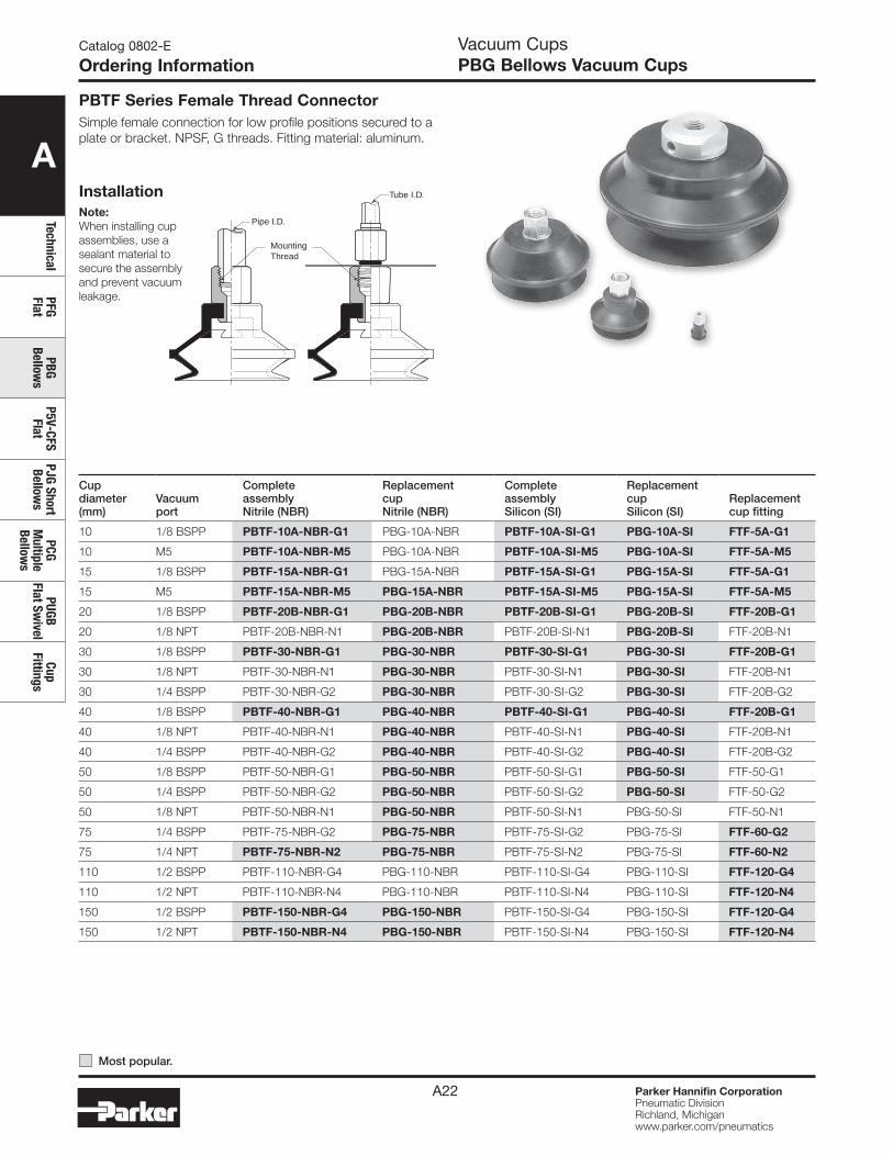
Vacuum CupsPBG Bellows Vacuum Cups
Tube I.D.
Pipe I.D.
MountingThread
Note:When installing cup assemblies, use a sealant material to secure the assembly and prevent vacuum leakage.
PBTF Series Female Thread ConnectorSimple female connection for low profile positions secured to a plate or bracket. NPSF, G threads. Fitting material: aluminum.
Installation
Catalog 0802-E
Ordering Information
Cup diameter (mm)
Vacuumport
Complete assembly Nitrile (NBR)
Replacement cup Nitrile (NBR)
Complete assembly Silicon (SI)
Replacement cup Silicon (SI)
Replacement cup fitting
10 1/8 BSPP PBTF-10A-NBR-G1 PBG-10A-NBR PBTF-10A-SI-G1 PBG-10A-SI FTF-5A-G1
10 M5 PBTF-10A-NBR-M5 PBG-10A-NBR PBTF-10A-SI-M5 PBG-10A-SI FTF-5A-M5
15 1/8 BSPP PBTF-15A-NBR-G1 PBG-15A-NBR PBTF-15A-SI-G1 PBG-15A-SI FTF-5A-G1
15 M5 PBTF-15A-NBR-M5 PBG-15A-NBR PBTF-15A-SI-M5 PBG-15A-SI FTF-5A-M5
20 1/8 BSPP PBTF-20B-NBR-G1 PBG-20B-NBR PBTF-20B-SI-G1 PBG-20B-SI FTF-20B-G1
20 1/8 NPT PBTF-20B-NBR-N1 PBG-20B-NBR PBTF-20B-SI-N1 PBG-20B-SI FTF-20B-N1
30 1/8 BSPP PBTF-30-NBR-G1 PBG-30-NBR PBTF-30-SI-G1 PBG-30-SI FTF-20B-G1
30 1/8 NPT PBTF-30-NBR-N1 PBG-30-NBR PBTF-30-SI-N1 PBG-30-SI FTF-20B-N1
30 1/4 BSPP PBTF-30-NBR-G2 PBG-30-NBR PBTF-30-SI-G2 PBG-30-SI FTF-20B-G2
40 1/8 BSPP PBTF-40-NBR-G1 PBG-40-NBR PBTF-40-SI-G1 PBG-40-SI FTF-20B-G1
40 1/8 NPT PBTF-40-NBR-N1 PBG-40-NBR PBTF-40-SI-N1 PBG-40-SI FTF-20B-N1
40 1/4 BSPP PBTF-40-NBR-G2 PBG-40-NBR PBTF-40-SI-G2 PBG-40-SI FTF-20B-G2
50 1/8 BSPP PBTF-50-NBR-G1 PBG-50-NBR PBTF-50-SI-G1 PBG-50-SI FTF-50-G1
50 1/4 BSPP PBTF-50-NBR-G2 PBG-50-NBR PBTF-50-SI-G2 PBG-50-SI FTF-50-G2
50 1/8 NPT PBTF-50-NBR-N1 PBG-50-NBR PBTF-50-SI-N1 PBG-50-SI FTF-50-N1
75 1/4 BSPP PBTF-75-NBR-G2 PBG-75-NBR PBTF-75-SI-G2 PBG-75-SI FTF-60-G2
75 1/4 NPT PBTF-75-NBR-N2 PBG-75-NBR PBTF-75-SI-N2 PBG-75-SI FTF-60-N2
110 1/2 BSPP PBTF-110-NBR-G4 PBG-110-NBR PBTF-110-SI-G4 PBG-110-SI FTF-120-G4
110 1/2 NPT PBTF-110-NBR-N4 PBG-110-NBR PBTF-110-SI-N4 PBG-110-SI FTF-120-N4
150 1/2 BSPP PBTF-150-NBR-G4 PBG-150-NBR PBTF-150-SI-G4 PBG-150-SI FTF-120-G4
150 1/2 NPT PBTF-150-NBR-N4 PBG-150-NBR PBTF-150-SI-N4 PBG-150-SI FTF-120-N4
Most popular.
A
Tech
nica
lPF
G Fl
atPB
G Be
llow
sP5
V-CF
S Fl
atPJ
G Sh
ort
Bello
ws
PCG
Mul
tiple
Be
llow
s
PUGB
Fl
at S
wiv
elCu
p Fi
tting
s
Parker Hannifin CorporationPneumatic DivisionRichland, Michiganwww.parker.com/pneumatics
A23
Vacuum CupsPBG Bellows Vacuum Cups
Installation
Catalog 0802-E
Ordering Information
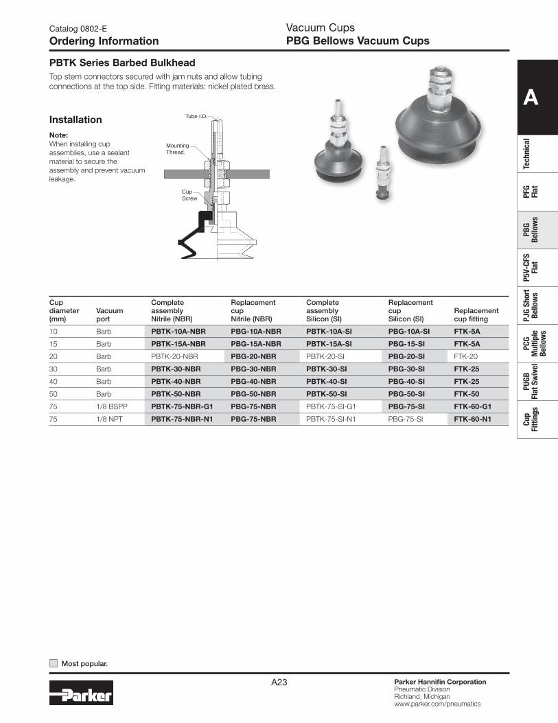
PBTK Series Barbed BulkheadTop stem connectors secured with jam nuts and allow tubing connections at the top side. Fitting materials: nickel plated brass.
Tube I.D.
MountingThread.
CupScrew
Note:When installing cup assemblies, use a sealant material to secure the assembly and prevent vacuum leakage.
Cup diameter (mm)
Vacuumport
Complete assembly Nitrile (NBR)
Replacement cup Nitrile (NBR)
Complete assembly Silicon (SI)
Replacement cup Silicon (SI)
Replacement cup fitting
10 Barb PBTK-10A-NBR PBG-10A-NBR PBTK-10A-SI PBG-10A-SI FTK-5A
15 Barb PBTK-15A-NBR PBG-15A-NBR PBTK-15A-SI PBG-15-SI FTK-5A
20 Barb PBTK-20-NBR PBG-20-NBR PBTK-20-SI PBG-20-SI FTK-20
30 Barb PBTK-30-NBR PBG-30-NBR PBTK-30-SI PBG-30-SI FTK-25
40 Barb PBTK-40-NBR PBG-40-NBR PBTK-40-SI PBG-40-SI FTK-25
50 Barb PBTK-50-NBR PBG-50-NBR PBTK-50-SI PBG-50-SI FTK-50
75 1/8 BSPP PBTK-75-NBR-G1 PBG-75-NBR PBTK-75-SI-G1 PBG-75-SI FTK-60-G1
75 1/8 NPT PBTK-75-NBR-N1 PBG-75-NBR PBTK-75-SI-N1 PBG-75-SI FTK-60-N1
Most popular.
A
TechnicalPFG Flat
PBG Bellow
sP5V-CFS
FlatPJG Short Bellow
sPCG
Multiple
Bellows
PUGB Flat Sw
ivelCup
Fittings
Parker Hannifin CorporationPneumatic DivisionRichland, Michiganwww.parker.com/pneumatics
A24
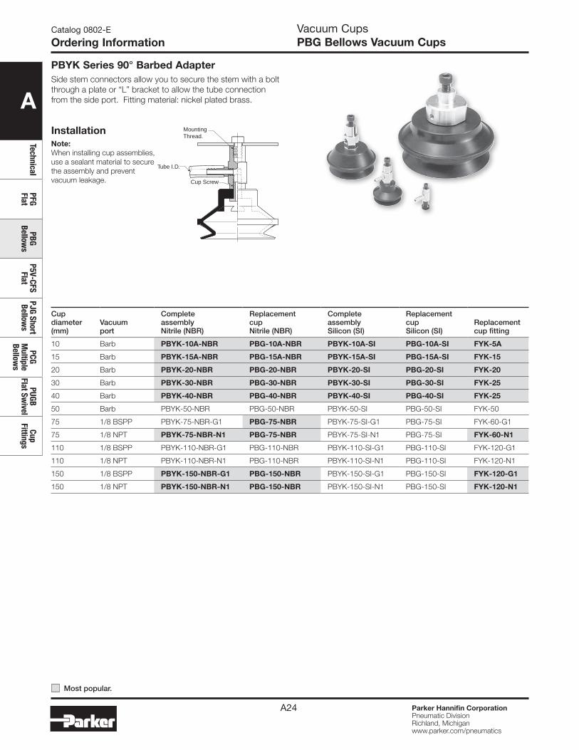
Tube I.D.
MountingThread.
Cup Screw
Note:When installing cup assemblies, use a sealant material to secure the assembly and prevent vacuum leakage.
PBYK Series 90° Barbed AdapterSide stem connectors allow you to secure the stem with a bolt through a plate or “L” bracket to allow the tube connection from the side port. Fitting material: nickel plated brass.
Installation
Vacuum CupsPBG Bellows Vacuum Cups
Catalog 0802-E
Ordering Information
Cup diameter (mm)
Vacuumport
Complete assembly Nitrile (NBR)
Replacement cup Nitrile (NBR)
Complete assembly Silicon (SI)
Replacement cup Silicon (SI)
Replacement cup fitting
10 Barb PBYK-10A-NBR PBG-10A-NBR PBYK-10A-SI PBG-10A-SI FYK-5A
15 Barb PBYK-15A-NBR PBG-15A-NBR PBYK-15A-SI PBG-15A-SI FYK-15
20 Barb PBYK-20-NBR PBG-20-NBR PBYK-20-SI PBG-20-SI FYK-20
30 Barb PBYK-30-NBR PBG-30-NBR PBYK-30-SI PBG-30-SI FYK-25
40 Barb PBYK-40-NBR PBG-40-NBR PBYK-40-SI PBG-40-SI FYK-25
50 Barb PBYK-50-NBR PBG-50-NBR PBYK-50-SI PBG-50-SI FYK-50
75 1/8 BSPP PBYK-75-NBR-G1 PBG-75-NBR PBYK-75-SI-G1 PBG-75-SI FYK-60-G1
75 1/8 NPT PBYK-75-NBR-N1 PBG-75-NBR PBYK-75-SI-N1 PBG-75-SI FYK-60-N1
110 1/8 BSPP PBYK-110-NBR-G1 PBG-110-NBR PBYK-110-SI-G1 PBG-110-SI FYK-120-G1
110 1/8 NPT PBYK-110-NBR-N1 PBG-110-NBR PBYK-110-SI-N1 PBG-110-SI FYK-120-N1
150 1/8 BSPP PBYK-150-NBR-G1 PBG-150-NBR PBYK-150-SI-G1 PBG-150-SI FYK-120-G1
150 1/8 NPT PBYK-150-NBR-N1 PBG-150-NBR PBYK-150-SI-N1 PBG-150-SI FYK-120-N1
Most popular.
A
Tech
nica
lPF
G Fl
atPB
G Be
llow
sP5
V-CF
S Fl
atPJ
G Sh
ort
Bello
ws
PCG
Mul
tiple
Be
llow
s
PUGB
Fl
at S
wiv
elCu
p Fi
tting
s
Parker Hannifin CorporationPneumatic DivisionRichland, Michiganwww.parker.com/pneumatics
A25
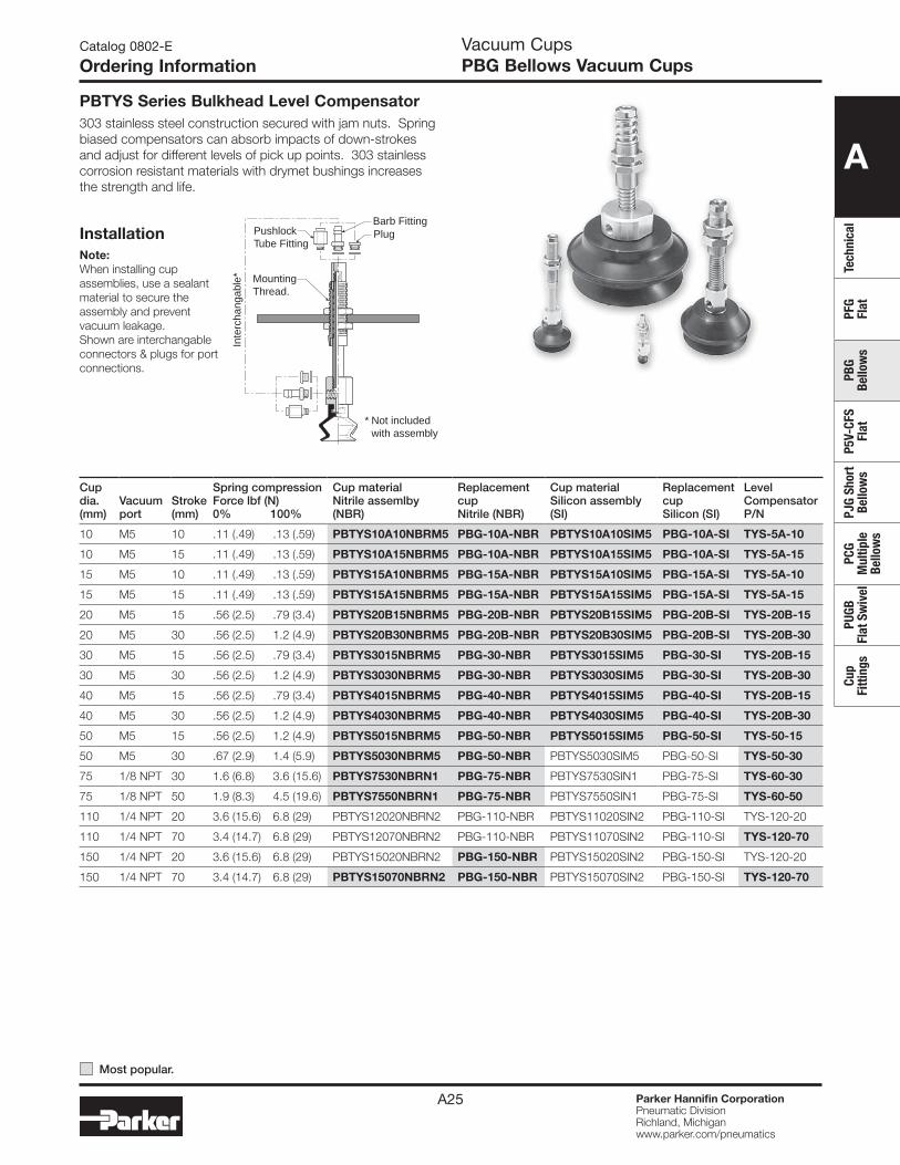
PBTYS Series Bulkhead Level Compensator303 stainless steel construction secured with jam nuts. Spring biased compensators can absorb impacts of down-strokes and adjust for different levels of pick up points. 303 stainless corrosion resistant materials with drymet bushings increases the strength and life.
Installation
Vacuum CupsPBG Bellows Vacuum Cups
Catalog 0802-E
Ordering Information
MountingThread.
PlugPushlockTube Fitting
Barb Fitting
Inte
rcha
ngab
le*
* Not included with assembly
Note:When installing cup assemblies, use a sealant material to secure the assembly and prevent vacuum leakage.Shown are interchangable connectors & plugs for port connections.
Cup dia. (mm)
Vacuumport
Stroke (mm)
Spring compression Force lbf (N)0% 100%
Cup material Nitrile assemlby (NBR)
Replacement cup Nitrile (NBR)
Cup material Silicon assembly (SI)
Replacement cup Silicon (SI)
Level Compensator P/N
10 M5 10 .11 (.49) .13 (.59) PBTYS10A10NBRM5 PBG-10A-NBR PBTYS10A10SIM5 PBG-10A-SI TYS-5A-10
10 M5 15 .11 (.49) .13 (.59) PBTYS10A15NBRM5 PBG-10A-NBR PBTYS10A15SIM5 PBG-10A-SI TYS-5A-15
15 M5 10 .11 (.49) .13 (.59) PBTYS15A10NBRM5 PBG-15A-NBR PBTYS15A10SIM5 PBG-15A-SI TYS-5A-10
15 M5 15 .11 (.49) .13 (.59) PBTYS15A15NBRM5 PBG-15A-NBR PBTYS15A15SIM5 PBG-15A-SI TYS-5A-15
20 M5 15 .56 (2.5) .79 (3.4) PBTYS20B15NBRM5 PBG-20B-NBR PBTYS20B15SIM5 PBG-20B-SI TYS-20B-15
20 M5 30 .56 (2.5) 1.2 (4.9) PBTYS20B30NBRM5 PBG-20B-NBR PBTYS20B30SIM5 PBG-20B-SI TYS-20B-30
30 M5 15 .56 (2.5) .79 (3.4) PBTYS3015NBRM5 PBG-30-NBR PBTYS3015SIM5 PBG-30-SI TYS-20B-15
30 M5 30 .56 (2.5) 1.2 (4.9) PBTYS3030NBRM5 PBG-30-NBR PBTYS3030SIM5 PBG-30-SI TYS-20B-30
40 M5 15 .56 (2.5) .79 (3.4) PBTYS4015NBRM5 PBG-40-NBR PBTYS4015SIM5 PBG-40-SI TYS-20B-15
40 M5 30 .56 (2.5) 1.2 (4.9) PBTYS4030NBRM5 PBG-40-NBR PBTYS4030SIM5 PBG-40-SI TYS-20B-30
50 M5 15 .56 (2.5) 1.2 (4.9) PBTYS5015NBRM5 PBG-50-NBR PBTYS5015SIM5 PBG-50-SI TYS-50-15
50 M5 30 .67 (2.9) 1.4 (5.9) PBTYS5030NBRM5 PBG-50-NBR PBTYS5030SIM5 PBG-50-SI TYS-50-30
75 1/8 NPT 30 1.6 (6.8) 3.6 (15.6) PBTYS7530NBRN1 PBG-75-NBR PBTYS7530SIN1 PBG-75-SI TYS-60-30
75 1/8 NPT 50 1.9 (8.3) 4.5 (19.6) PBTYS7550NBRN1 PBG-75-NBR PBTYS7550SIN1 PBG-75-SI TYS-60-50
110 1/4 NPT 20 3.6 (15.6) 6.8 (29) PBTYS12020NBRN2 PBG-110-NBR PBTYS11020SIN2 PBG-110-SI TYS-120-20
110 1/4 NPT 70 3.4 (14.7) 6.8 (29) PBTYS12070NBRN2 PBG-110-NBR PBTYS11070SIN2 PBG-110-SI TYS-120-70
150 1/4 NPT 20 3.6 (15.6) 6.8 (29) PBTYS15020NBRN2 PBG-150-NBR PBTYS15020SIN2 PBG-150-SI TYS-120-20
150 1/4 NPT 70 3.4 (14.7) 6.8 (29) PBTYS15070NBRN2 PBG-150-NBR PBTYS15070SIN2 PBG-150-SI TYS-120-70
Most popular.
A
TechnicalPFG Flat
PBG Bellow
sP5V-CFS
FlatPJG Short Bellow
sPCG
Multiple
Bellows
PUGB Flat Sw
ivelCup
Fittings
Parker Hannifin CorporationPneumatic DivisionRichland, Michiganwww.parker.com/pneumatics
A26
Catalog 0802-E
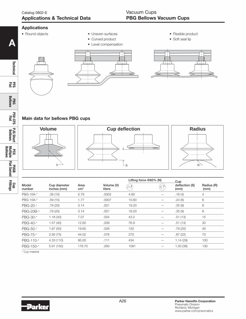
Applications & Technical Data
Modelnumber
Cup diameterinches (mm)
Areacm2
Volume (V) liters
Lifting force @60% (N) Cupdeflection (S)(mm)
Radius (R) (mm)
PBG-10A-* .39 (10) 0.79 .0002 4.80 — .16 (4) 4
PBG-15A-* .59 (15) 1.77 .0007 10.80 — .24 (6) 6
PBG-20-* .79 (20) 3.14 .001 19.20 — .35 (9) 8
PBG-20B-* .79 (20) 3.14 .001 19.20 — .35 (9) 8
PBG-30-* 1.18 (30) 7.07 .004 43.2 — .51 (13) 15
PBG-40-* 1.57 (40) 12.60 .009 76.9 — .51 (13) 30
PBG-50-* 1.97 (50) 19.60 .026 120 — .79 (20) 40
PBG-75-* 2.95 (75) 44.02 .076 270 — .87 (22) 70
PBG-110-* 4.33 (110) 95.00 .111 434 — 1.14 (29) 100
PBG-150-* 5.91 (150) 176.70 .260 1081 — 1.50 (38) 130
* Cup material
Main data for bellows PBG cups
S RV
Volume RadiusCup deflection
• Round objects • Uneven surfaces• Curved product• Level compensation
• Flexible product• Soft seal lip
Vacuum CupsPBG Bellows Vacuum Cups
Applications
A
Tech
nica
lPF
G Fl
atPB
G Be
llow
sP5
V-CF
S Fl
atPJ
G Sh
ort
Bello
ws
PCG
Mul
tiple
Be
llow
s
PUGB
Fl
at S
wiv
elCu
p Fi
tting
s
Parker Hannifin CorporationPneumatic DivisionRichland, Michiganwww.parker.com/pneumatics
A27
E
AC
JD
B
F
G
H
EF
AC
DB
H
A
C
D
B
E
F
H
E
A
D
B M10x1.25
F
H
A
D
C
BG
E
F
H
A
D
C
BG
E
F
H
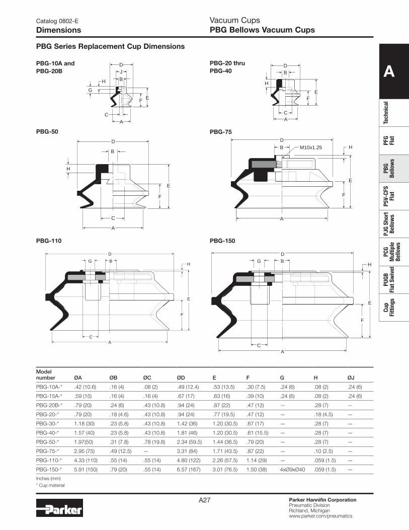
Modelnumber ØA ØB ØC ØD E F G H ØJ
PBG-10A-* .42 (10.6) .16 (4) .08 (2) .49 (12.4) .53 (13.5) .30 (7.5) .24 (6) .08 (2) .24 (6)
PBG-15A-* .59 (15) .16 (4) .16 (4) .67 (17) .63 (16) .39 (10) .24 (6) .08 (2) .24 (6)
PBG-20B-* .79 (20) .24 (6) .43 (10.8) .94 (24) .87 (22) .47 (12) — .28 (7) —
PBG-20-* .79 (20) .18 (4.6) .43 (10.8) .94 (24) .77 (19.5) .47 (12) — .18 (4.5) —
PBG-30-* 1.18 (30) .23 (5.8) .43 (10.8) 1.42 (36) 1.20 (30.5) .67 (17) — .28 (7) —
PBG-40-* 1.57 (40) .23 (5.8) .43 (10.8) 1.81 (46) 1.20 (30.5) .61 (15.5) — .28 (7) —
PBG-50-* 1.97(50) .31 (7.8) .78 (19.8) 2.34 (59.5) 1.44 (36.5) .79 (20) — .28 (7) —
PBG-75-* 2.95 (75) .49 (12.5) — 3.31 (84) 1.71 (43.5) .87 (22) — .10 (2.5) —
PBG-110-* 4.33 (110) .55 (14) .55 (14) 4.80 (122) 2.26 (57.5) 1.14 (29) — .059 (1.5) —
PBG-150-* 5.91 (150) .79 (20) .55 (14) 6.57 (167) 3.01 (76.5) 1.50 (38) 4xØ9xØ40 .059 (1.5) —
Inches (mm)* Cup material
Catalog 0802-E
Dimensions
PBG-10A andPBG-20B
PBG-50 PBG-75
PBG-110 PBG-150
PBG-20 thruPBG-40
PBG Series Replacement Cup Dimensions
Vacuum CupsPBG Bellows Vacuum Cups
A
TechnicalPFG Flat
PBG Bellow
sP5V-CFS
FlatPJG Short Bellow
sPCG
Multiple
Bellows
PUGB Flat Sw
ivelCup
Fittings
Parker Hannifin CorporationPneumatic DivisionRichland, Michiganwww.parker.com/pneumatics
A28
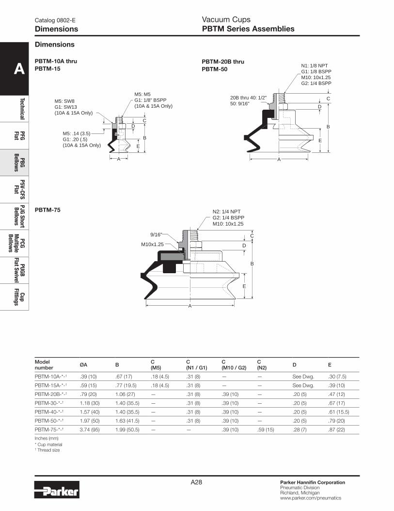
PBTM-10A thru PBTM-15
PBTM-20B thru PBTM-50
PBTM-75
N1: 1/8 NPTG1: 1/8 BSPPM10: 10x1.25G2: 1/4 BSPP
20B thru 40: 1/2"50: 9/16"
A
E
B
C
D
B
C
D
E
N2: 1/4 NPTG2: 1/4 BSPPM10: 10x1.25
9/16"
M10x1.25
A
Modelnumber ØA B C
(M5)C(N1 / G1)
C(M10 / G2)
C(N2) D E
PBTM-10A-*-† .39 (10) .67 (17) .18 (4.5) .31 (8) — — See Dwg. .30 (7.5)
PBTM-15A-*-† .59 (15) .77 (19.5) .18 (4.5) .31 (8) — — See Dwg. .39 (10)
PBTM-20B-*-† .79 (20) 1.06 (27) — .31 (8) .39 (10) — .20 (5) .47 (12)
PBTM-30-*-† 1.18 (30) 1.40 (35.5) — .31 (8) .39 (10) — .20 (5) .67 (17)
PBTM-40-*-† 1.57 (40) 1.40 (35.5) — .31 (8) .39 (10) — .20 (5) .61 (15.5)
PBTM-50-*-† 1.97 (50) 1.63 (41.5) — .31 (8) .39 (10) — .20 (5) .79 (20)
PBTM-75-*-† 3.74 (95) 1.99 (50.5) — — .39 (10) .59 (15) .28 (7) .87 (22)
Inches (mm)* Cup material † Thread size
A
E
B
CD
M5: M5G1: 1/8" BSPP(10A & 15A Only)
M5: SW8G1: SW13(10A & 15A Only)
M5: .14 (3.5)G1: .20 (.5)(10A & 15A Only)
Dimensions
Catalog 0802-E
DimensionsVacuum CupsPBTM Series Assemblies
A
Tech
nica
lPF
G Fl
atPB
G Be
llow
sP5
V-CF
S Fl
atPJ
G Sh
ort
Bello
ws
PCG
Mul
tiple
Be
llow
s
PUGB
Fl
at S
wiv
elCu
p Fi
tting
s
Parker Hannifin CorporationPneumatic DivisionRichland, Michiganwww.parker.com/pneumatics
A29
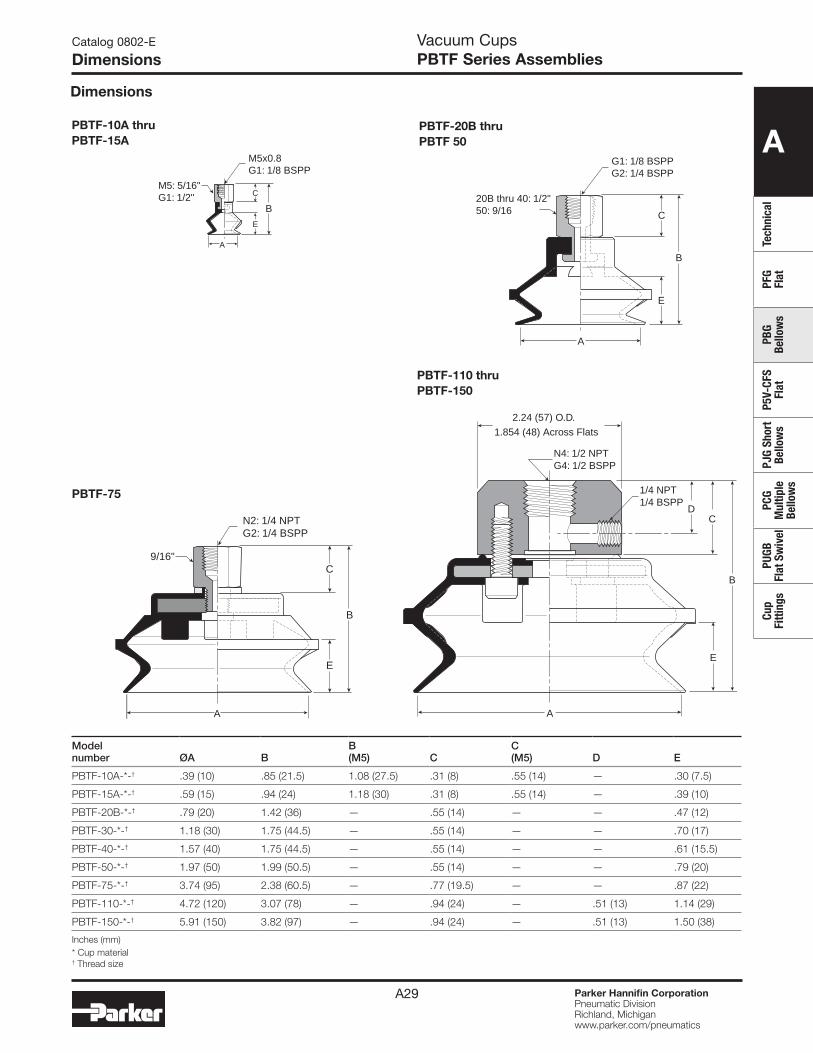
PBTF-10A thru PBTF-15A
PBTF-20B thruPBTF 50
PBTF-110 thru PBTF-150
Modelnumber ØA B
B(M5) C
C(M5) D E
PBTF-10A-*-† .39 (10) .85 (21.5) 1.08 (27.5) .31 (8) .55 (14) — .30 (7.5)
PBTF-15A-*-† .59 (15) .94 (24) 1.18 (30) .31 (8) .55 (14) — .39 (10)
PBTF-20B-*-† .79 (20) 1.42 (36) — .55 (14) — — .47 (12)
PBTF-30-*-† 1.18 (30) 1.75 (44.5) — .55 (14) — — .70 (17)
PBTF-40-*-† 1.57 (40) 1.75 (44.5) — .55 (14) — — .61 (15.5)
PBTF-50-*-† 1.97 (50) 1.99 (50.5) — .55 (14) — — .79 (20)
PBTF-75-*-† 3.74 (95) 2.38 (60.5) — .77 (19.5) — — .87 (22)
PBTF-110-*-† 4.72 (120) 3.07 (78) — .94 (24) — .51 (13) 1.14 (29)
PBTF-150-*-† 5.91 (150) 3.82 (97) — .94 (24) — .51 (13) 1.50 (38)
Inches (mm)* Cup material † Thread size
G1: 1/8 BSPPG2: 1/4 BSPP
20B thru 40: 1/2"50: 9/16
A
E
C
B
A
N4: 1/2 NPTG4: 1/2 BSPP
1/4 NPT1/4 BSPP
B
D
E
C
2.24 (57) O.D.
1.854 (48) Across Flats
Dimensions
PBTF-75
B
E
C
N2: 1/4 NPTG2: 1/4 BSPP
9/16"
A
A
M5x0.8G1: 1/8 BSPP
M5: 5/16"G1: 1/2"
B
E
C
Catalog 0802-E
DimensionsVacuum CupsPBTF Series Assemblies
A
TechnicalPFG Flat
PBG Bellow
sP5V-CFS
FlatPJG Short Bellow
sPCG
Multiple
Bellows
PUGB Flat Sw
ivelCup
Fittings
Parker Hannifin CorporationPneumatic DivisionRichland, Michiganwww.parker.com/pneumatics
A30
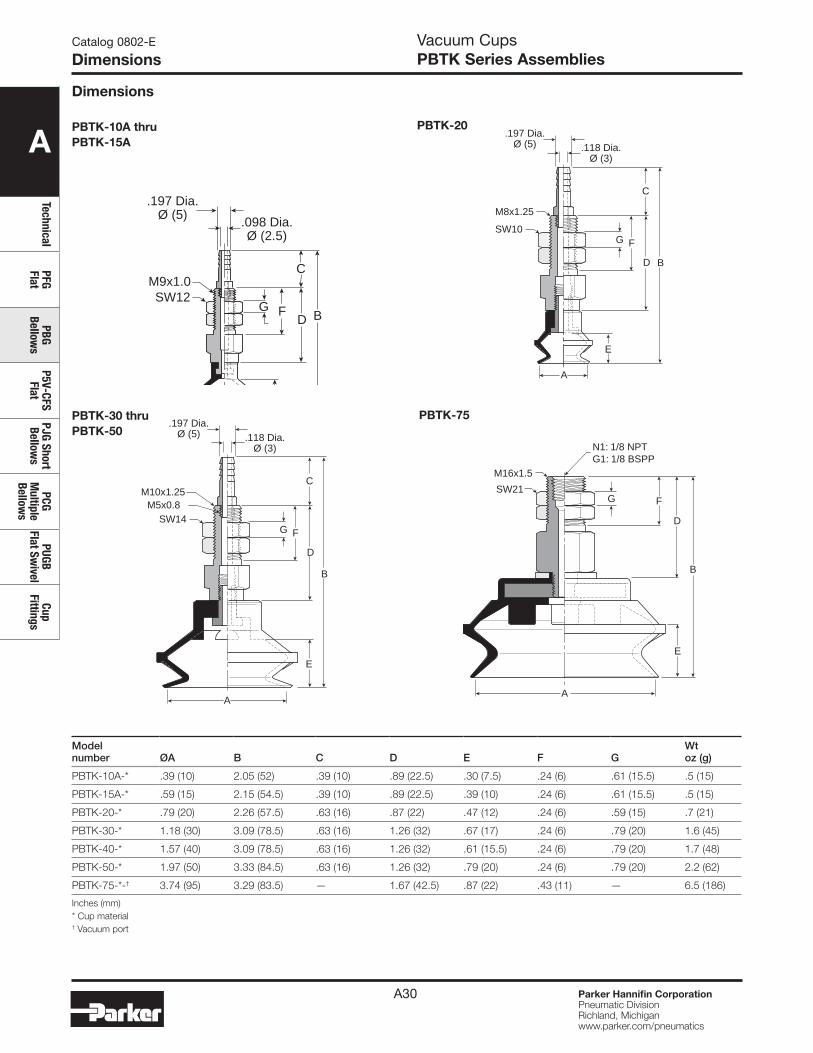
PBTK-10A thru PBTK-15A
PBTK-20
E
A
.197 Dia.Ø (5)
.098 Dia.Ø (2.5)
FG
C
D B
M9x1.0SW12
PBTK-75
A
N1: 1/8 NPTG1: 1/8 BSPP
SW21
M16x1.5
B
FG
D
E
A
B
FG
C
D
M8x1.25
SW10
.197 Dia.Ø (5) .118 Dia.
Ø (3)
E
Dimensions
PBTK-30 thru PBTK-50
A
B
FG
C
D
E
M10x1.25
SW14
.197 Dia.Ø (5) .118 Dia.
Ø (3)
M5x0.8
Modelnumber ØA B C D E F G
Wtoz (g)
PBTK-10A-* .39 (10) 2.05 (52) .39 (10) .89 (22.5) .30 (7.5) .24 (6) .61 (15.5) .5 (15)
PBTK-15A-* .59 (15) 2.15 (54.5) .39 (10) .89 (22.5) .39 (10) .24 (6) .61 (15.5) .5 (15)
PBTK-20-* .79 (20) 2.26 (57.5) .63 (16) .87 (22) .47 (12) .24 (6) .59 (15) .7 (21)
PBTK-30-* 1.18 (30) 3.09 (78.5) .63 (16) 1.26 (32) .67 (17) .24 (6) .79 (20) 1.6 (45)
PBTK-40-* 1.57 (40) 3.09 (78.5) .63 (16) 1.26 (32) .61 (15.5) .24 (6) .79 (20) 1.7 (48)
PBTK-50-* 1.97 (50) 3.33 (84.5) .63 (16) 1.26 (32) .79 (20) .24 (6) .79 (20) 2.2 (62)
PBTK-75-*-† 3.74 (95) 3.29 (83.5) — 1.67 (42.5) .87 (22) .43 (11) — 6.5 (186)
Inches (mm)* Cup material† Vacuum port
Catalog 0802-E
DimensionsVacuum CupsPBTK Series Assemblies
A
Tech
nica
lPF
G Fl
atPB
G Be
llow
sP5
V-CF
S Fl
atPJ
G Sh
ort
Bello
ws
PCG
Mul
tiple
Be
llow
s
PUGB
Fl
at S
wiv
elCu
p Fi
tting
s
Parker Hannifin CorporationPneumatic DivisionRichland, Michiganwww.parker.com/pneumatics
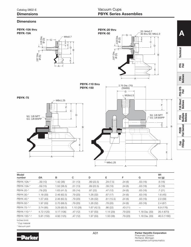
A31
PBYK-75
PBYK-110 thru PBYK-150
Modelnumber ØA B C D E F G
Wtoz (g)
PBYK-10A-* .39 (10) 1.42 (36) .51 (13) .89 (22.5) .29 (7.5) .24 (6) .63 (16) .6 (16)
PBYK-15A-* .59 (15) 1.52 (38.5) .51 (13) .89 (22.5) .39 (10) .24 (6) .63 (16) .6 (16)
PBYK-20-* .79 (20) 1.63 (41.5) .55 (14) .87 (22) .47 (12) .24 (6) .63 (16) .7 (21)
PBYK-30-* 1.18 (30) 2.46 (62.5) .79 (20) 1.26 (32) .67 (17) .24 (6) .63 (16) 1.6 (45)
PBYK-40-* 1.57 (40) 2.46 (62.5) .79 (20) 1.26 (32) .61 (15.5) .24 (6) .63 (16) 2.0 (58)
PBYK-50-* 1.97 (50) 2.70 (68.5) .79 (20) 1.26 (32) .78 (20) .24 (6) .63 (16) 2.4 (67)
PBYK-75-*-† 3.74 (95) 3.29 (83.5) 1.10 (28) 1.67 (42.5) .86 (22) .43 (11) — 6.9 (176)
PBYK-110-*-† 4.72 (120) 4.17 (106) .47 (12) 1.97 (50) 1.14 (29) .79 (20) 1.18 Dia. (30) 26.4 (670)
PBYK-150-*-† 5.91 (150) 4.92 (125) .47 (12) 1.97 (50) 1.50 (38) .79 (20) 1.18 Dia. (30) 46.5 (1180)
Inches (mm)* Cup material† Vacuum port
PBYK-10A thru PBYK-15A
FC
DB
E.197
Dia
.Ø
(5)
.118
Dia
.Ø
(3)
M4x0.7G
A
PBYK-20 thru PBYK-50
M8x1.25
B
F
N1: 1/8 NPTG1: 1/8 BSPP
C
D
E
A
A
2.75 Dia. (70)(SW65)
G
M16x1.5
N1: 1/8 NPTG1: 1/8 BSPP
M8x1.25
BC
D
E
F
B
F
G
20: M4x0.730 thru 50: M6x1.0
C
D
E
.197
Dia
.Ø
(5)
.118
Dia
.Ø
(3)
A
Dimensions
Catalog 0802-E
DimensionsVacuum CupsPBYK Series Assemblies
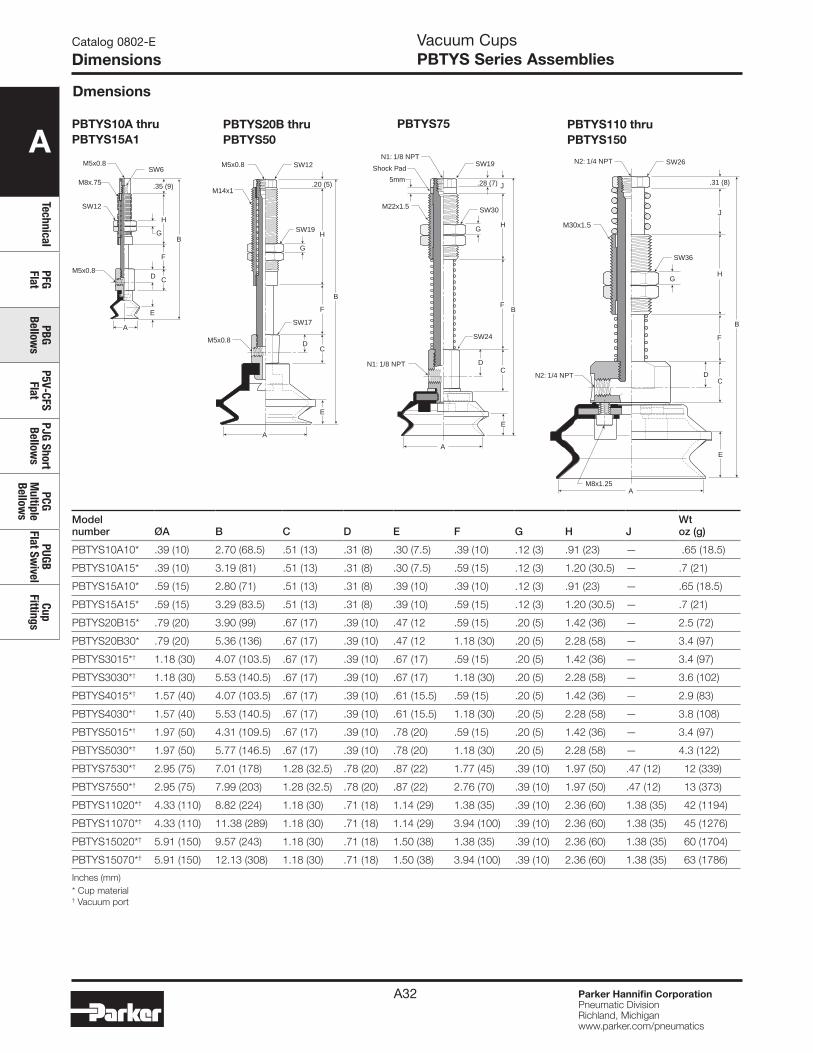
A
TechnicalPFG Flat
PBG Bellow
sP5V-CFS
FlatPJG Short Bellow
sPCG
Multiple
Bellows
PUGB Flat Sw
ivelCup
Fittings
Parker Hannifin CorporationPneumatic DivisionRichland, Michiganwww.parker.com/pneumatics
A32
PBTYS20B thruPBTYS50
PBTYS10A thruPBTYS15A1
PBTYS75 PBTYS110 thruPBTYS150
Dmensions
M5x0.8
M5x0.8
SW6
SW12
M8x.75
B
D C
F
.35 (9)
H
G
E
A
M5x0.8
M5x0.8
SW12
SW19
SW17
M14x1
B
D
E
C
H
.20 (5)
F
G
A
N1: 1/8 NPT
N1: 1/8 NPT
SW19
SW30
SW24
M22x1.5
B
D
A
E
C
H
J.28 (7)
F
G
Shock Pad
5mm
AM8x1.25
SW26
SW36
M30x1.5
B
D
E
C
J
.31 (8)
F
HG
N2: 1/4 NPT
N2: 1/4 NPT
Modelnumber ØA B C D E F G H J
Wtoz (g)
PBTYS10A10* .39 (10) 2.70 (68.5) .51 (13) .31 (8) .30 (7.5) .39 (10) .12 (3) .91 (23) — .65 (18.5)
PBTYS10A15* .39 (10) 3.19 (81) .51 (13) .31 (8) .30 (7.5) .59 (15) .12 (3) 1.20 (30.5) — .7 (21)
PBTYS15A10* .59 (15) 2.80 (71) .51 (13) .31 (8) .39 (10) .39 (10) .12 (3) .91 (23) — .65 (18.5)
PBTYS15A15* .59 (15) 3.29 (83.5) .51 (13) .31 (8) .39 (10) .59 (15) .12 (3) 1.20 (30.5) — .7 (21)
PBTYS20B15* .79 (20) 3.90 (99) .67 (17) .39 (10) .47 (12 .59 (15) .20 (5) 1.42 (36) — 2.5 (72)
PBTYS20B30* .79 (20) 5.36 (136) .67 (17) .39 (10) .47 (12 1.18 (30) .20 (5) 2.28 (58) — 3.4 (97)
PBTYS3015*† 1.18 (30) 4.07 (103.5) .67 (17) .39 (10) .67 (17) .59 (15) .20 (5) 1.42 (36) — 3.4 (97)
PBTYS3030*† 1.18 (30) 5.53 (140.5) .67 (17) .39 (10) .67 (17) 1.18 (30) .20 (5) 2.28 (58) — 3.6 (102)
PBTYS4015*† 1.57 (40) 4.07 (103.5) .67 (17) .39 (10) .61 (15.5) .59 (15) .20 (5) 1.42 (36) — 2.9 (83)
PBTYS4030*† 1.57 (40) 5.53 (140.5) .67 (17) .39 (10) .61 (15.5) 1.18 (30) .20 (5) 2.28 (58) — 3.8 (108)
PBTYS5015*† 1.97 (50) 4.31 (109.5) .67 (17) .39 (10) .78 (20) .59 (15) .20 (5) 1.42 (36) — 3.4 (97)
PBTYS5030*† 1.97 (50) 5.77 (146.5) .67 (17) .39 (10) .78 (20) 1.18 (30) .20 (5) 2.28 (58) — 4.3 (122)
PBTYS7530*† 2.95 (75) 7.01 (178) 1.28 (32.5) .78 (20) .87 (22) 1.77 (45) .39 (10) 1.97 (50) .47 (12) 12 (339)
PBTYS7550*† 2.95 (75) 7.99 (203) 1.28 (32.5) .78 (20) .87 (22) 2.76 (70) .39 (10) 1.97 (50) .47 (12) 13 (373)
PBTYS11020*† 4.33 (110) 8.82 (224) 1.18 (30) .71 (18) 1.14 (29) 1.38 (35) .39 (10) 2.36 (60) 1.38 (35) 42 (1194)
PBTYS11070*† 4.33 (110) 11.38 (289) 1.18 (30) .71 (18) 1.14 (29) 3.94 (100) .39 (10) 2.36 (60) 1.38 (35) 45 (1276)
PBTYS15020*† 5.91 (150) 9.57 (243) 1.18 (30) .71 (18) 1.50 (38) 1.38 (35) .39 (10) 2.36 (60) 1.38 (35) 60 (1704)
PBTYS15070*† 5.91 (150) 12.13 (308) 1.18 (30) .71 (18) 1.50 (38) 3.94 (100) .39 (10) 2.36 (60) 1.38 (35) 63 (1786)
Inches (mm)* Cup material † Vacuum port
Catalog 0802-E
DimensionsVacuum CupsPBTYS Series Assemblies
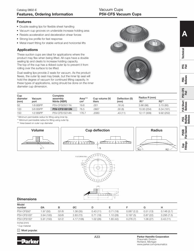
A
Tech
nica
lPF
G Fl
atPB
G Be
llow
sP5
V-CF
S Fl
atPJ
G Sh
ort
Bello
ws
PCG
Mul
tiple
Be
llow
s
PUGB
Fl
at S
wiv
elCu
p Fi
tting
s
Parker Hannifin CorporationPneumatic DivisionRichland, Michiganwww.parker.com/pneumatics
A33
Dimensions
Catalog 0802-E
Features, Ordering InformationVacuum CupsP5V-CFS Vacuum Cups
Features• Double sealing lips for flexible sheet handling• Vacuum cup grooves on underside increase holding area• Resists acceleration and deceleration shear forces• Strong low profile for fast response• Metal insert fitting for stable vertical and horizontal lifts
ApplicationsThese suction cups are ideal for applications where the product may flex when being lifted. All cups have a double sealing lip and cleats to increase holding capacity. The top of the cup has a ribbed outer lip to prevent it from rolling over the surface to be lifted.
Dual sealing lips provide 2 seals for vacuum. As the product flexes, the outer lip seal may break, but the inner lip seal will hold the degree of vacuum for continued lifting capacity. In these types of applications, sizing should be done on the inner diameter cup dimension.
S R1 R2V
Volume RadiusCup deflection
Model number ØA B ØC D E F G H
P5V-CFS50* 1.97 (50) G1/8 1.38 (35) 0.43 (11) 0.71 (18) 0.087 (2.2) 0.51 (13) 0.146 (3.7)
P5V-CFS100* 3.94 (100) G3/8 2.83 (72) 0.71 (18) 1.10 (28) 0.197 (5) 0.87 (22) 0.295 (7.5)
P5V-CFS150* 5.91 (150) G1/2 4.17 (106) 1.02 (26) 1.65 (42) 0.276 (7) 1.06 (27) 0.43 (11)Inches (mm)* Cup material
AC
B
ED
F
G
2.76(70)
H
G 1/2 (30018 Only)
Cup diameter (mm)
Vacuumport
Complete assembly Nitrile (NBR)
Area***cm2
Cup volume (V)liters
Deflection (S) (mm)
Radius R (mm)
R1* R2**
50 1/8 BSPP P5V-CFS05011N 19.6 .001 .16 (4) 3.86 (98) 3.15 (80)
100 3/8 BSPP P5V-CFS10013N 78.5 .0667 .30 (8) 10.00 (254) 6.34 (161)
150 1/2 BSPP P5V-CFS15014N 176.7 .2083 .43 (11) 12.17 (309) 9.92 (252)
* Minimum permissible radius for lifting using inner lip.** Minimum permissible radius for lifting using outer lip.*** Area based on outer cup diameter
Most popular.
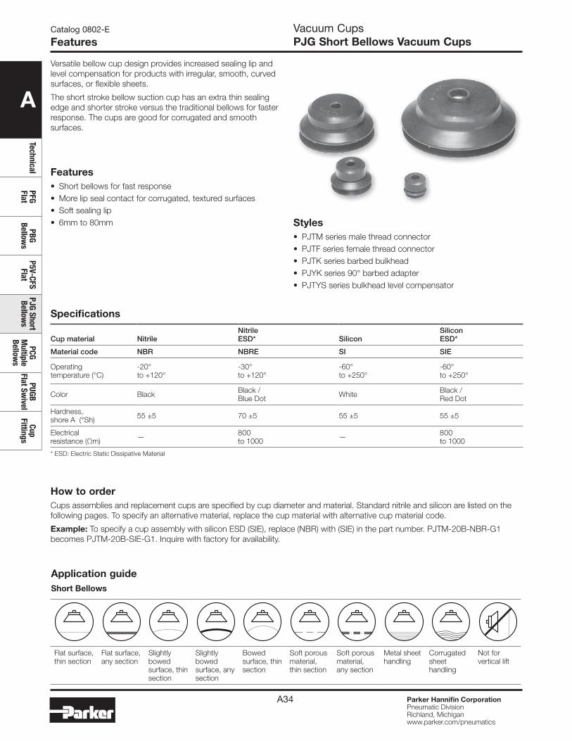
A
TechnicalPFG Flat
PBG Bellow
sP5V-CFS
FlatPJG Short Bellow
sPCG
Multiple
Bellows
PUGB Flat Sw
ivelCup
Fittings
Parker Hannifin CorporationPneumatic DivisionRichland, Michiganwww.parker.com/pneumatics
A34
Features• Short bellows for fast response• More lip seal contact for corrugated, textured surfaces• Soft sealing lip• 6mm to 80mm
Catalog 0802-E
FeaturesVacuum CupsPJG Short Bellows Vacuum Cups
Versatile bellow cup design provides increased sealing lip and level compensation for products with irregular, smooth, curved surfaces, or flexible sheets.
The short stroke bellow suction cup has an extra thin sealing edge and shorter stroke versus the traditional bellows for faster response. The cups are good for corrugated and smooth surfaces.
Specifications
Cup material NitrileNitrileESD* Silicon
SiliconESD*
Material code NBR NBRE SI SIE
Operating temperature (°C)
-20° to +120°
-30° to +120°
-60° to +250°
-60° to +250°
Color Black Black / Blue Dot White Black /
Red Dot
Hardness, shore A (°Sh) 55 ±5 70 ±5 55 ±5 55 ±5
Electrical resistance (Ωm) — 800
to 1000 — 800 to 1000
* ESD: Electric Static Dissipative Material
Styles• PJTM series male thread connector• PJTF series female thread connector• PJTK series barbed bulkhead• PJYK series 90° barbed adapter• PJTYS series bulkhead level compensator
How to orderCups assemblies and replacement cups are specified by cup diameter and material. Standard nitrile and silicon are listed on the following pages. To specify an alternative material, replace the cup material with alternative cup material code.
Example: To specify a cup assembly with silicon ESD (SIE), replace (NBR) with (SIE) in the part number. PJTM-20B-NBR-G1 becomes PJTM-20B-SIE-G1. Inquire with factory for availability.
Application guideShort Bellows
Flat surface, thin section
Flat surface, any section
Slightly bowed surface, thin section
Slightly bowed surface, any section
Bowed surface, thin section
Soft porous material, thin section
Soft porous material, any section
Metal sheet handling
Corrugated sheet handling
Not for vertical lift
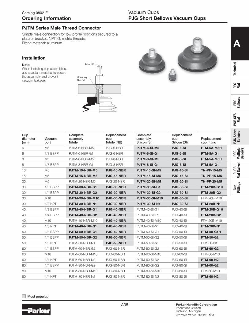
A
Tech
nica
lPF
G Fl
atPB
G Be
llow
sP5
V-CF
S Fl
atPJ
G Sh
ort
Bello
ws
PCG
Mul
tiple
Be
llow
s
PUGB
Fl
at S
wiv
elCu
p Fi
tting
s
Parker Hannifin CorporationPneumatic DivisionRichland, Michiganwww.parker.com/pneumatics
A35
Catalog 0802-E
Ordering InformationVacuum CupsPJG Short Bellows Vacuum Cups
Tube I.D.
MountingThread
InstallationNote:When installing cup assemblies, use a sealant material to secure the assembly and prevent vacuum leakage.
PJTM Series Male Thread ConnectorSimple male connection for low profile positions secured to a plate or bracket. NPT, G, metric threads. Fitting material: aluminum.
Cup diameter (mm)
Vacuumport
Complete assembly Nitrile
Replacement cup Nitrile (NB)
Complete assembly Silicon (SI)
Replacement cup Silicon (SI)
Replacement cup fitting
6 M5 PJTM-6-NBR-M5 PJG-6-NBR PJTM-6-SI-M5 PJG-6-SI FTM-5A-M5H
6 1/8 BSPP PJTM-6-NBR-G1 PJG-6-NBR PJTM-6-SI-G1 PJG-6-SI FTM-5A-G1
8 M5 PJTM-8-NBR-M5 PJG-8-NBR PJTM-8-SI-M5 PJG-8-SI FTM-5A-M5H
8 1/8 BSPP PJTM-8-NBR-G1 PJG-8-NBR PJTM-8-SI-G1 PJG-8-SI FTM-5A-G1
10 M5 PJTM-10-NBR-M5 PJG-10-NBR PJTM-10-SI-M5 PJG-10-SI TN-PF-15-M5
15 M5 PJTM-15-NBR-M5 PJG-15-NBR PJTM-15-SI-M5 PJG-15-SI TN-PF-15-M5
20 M5 PJTM-20-NBR-M5 PJG-20-NBR PJTM-20-SI-M5 PJG-20-SI TN-PF-20-M5
30 1/8 BSPP PJTM-30-NBR-G1 PJG-30-NBR PJTM-30-SI-G1 PJG-30-SI FTM-20B-G1H
30 1/4 BSPP PJTM-30-NBR-G2 PJG-30-NBR PJTM-30-SI-G2 PJG-30-SI FTM-20B-G2
30 M10 PJTM-30-NBR-M10 PJG-30-NBR PJTM-30-SI-M10 PJG-30-SI FTM-20B-M10
30 1/8 NPT PJTM-30-NBR-N1 PJG-30-NBR PJTM-30-SI-N1 PJG-30-SI FTM-20B-N1
40 1/8 BSPP PJTM-40-NBR-G1 PJG-40-NBR PJTM-40-SI-G1 PJG-40-SI FTM-20B-G1H
40 1/4 BSPP PJTM-40-NBR-G2 PJG-40-NBR PJTM-40-SI-G2 PJG-40-SI FTM-20B-G2
40 M10 PJTM-40-NBR-M10 PJG-40-NBR PJTM-40-SI-M10 PJG-40-SI FTM-20B-M10
40 1/8 NPT PJTM-40-NBR-N1 PJG-40-NBR PJTM-40-SI-N1 PJG-40-SI FTM-20B-N1
50 1/8 BSPP PJTM-50-NBR-G1 PJG-50-NBR PJTM-50-SI-G1 PJG-50-SI FTM-50-G1H
50 1/4 BSPP PJTM-50-NBR-G2 PJG-50-NBR PJTM-50-SI-G2 PJG-50-SI FTM-50-G2
50 1/8 NPT PJTM-50-NBR-N1 PJG-50-NBR PJTM-50-SI-N1 PJG-50-SI FTM-50-N1
60 1/4 BSPP PJTM-60-NBR-G2 PJG-60-NBR PJTM-60-SI-G2 PJG-60-SI FTM-60-G2
60 M10 PJTM-60-NBR-M10 PJG-60-NBR PJTM-60-SI-M10 PJG-60-SI FTM-60-M10
60 1/4 NPT PJTM-60-NBR-N2 PJG-60-NBR PJTM-60-SI-N2 PJG-60-SI FTM-60-N2
80 1/4 BSPP PJTM-80-NBR-G2 PJG-80-NBR PJTM-80-SI-G2 PJG-80-SI FTM-60-G2
80 M10 PJTM-80-NBR-M10 PJG-80-NBR PJTM-80-SI-M10 PJG-80-SI FTM-60-M10
80 1/4 NPT PJTM-80-NBR-N2 PJG-80-NBR PJTM-80-SI-N2 PJG-80-SI FTM-60-N2
Most popular.
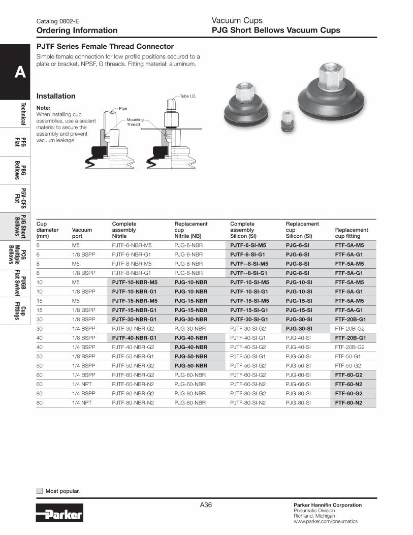
A
TechnicalPFG Flat
PBG Bellow
sP5V-CFS
FlatPJG Short Bellow
sPCG
Multiple
Bellows
PUGB Flat Sw
ivelCup
Fittings
Parker Hannifin CorporationPneumatic DivisionRichland, Michiganwww.parker.com/pneumatics
A36
Catalog 0802-E
Ordering InformationVacuum CupsPJG Short Bellows Vacuum Cups
Installation Tube I.D.
Pipe
MountingThread
Note:When installing cup assemblies, use a sealant material to secure the assembly and prevent vacuum leakage.
PJTF Series Female Thread ConnectorSimple female connection for low profile positions secured to a plate or bracket. NPSF, G threads. Fitting material: aluminum.
Cup diameter (mm)
Vacuumport
Complete assembly Nitrile
Replacement cup Nitrile (NB)
Complete assembly Silicon (SI)
Replacement cup Silicon (SI)
Replacement cup fitting
6 M5 PJTF-6-NBR-M5 PJG-6-NBR PJTF-6-SI-M5 PJG-6-SI FTF-5A-M5
6 1/8 BSPP PJTF-6-NBR-G1 PJG-6-NBR PJTF-6-SI-G1 PJG-6-SI FTF-5A-G1
8 M5 PJTF-8-NBR-M5 PJG-8-NBR PJTF--8-SI-M5 PJG-8-SI FTF-5A-M5
8 1/8 BSPP PJTF-8-NBR-G1 PJG-8-NBR PJTF--8-SI-G1 PJG-8-SI FTF-5A-G1
10 M5 PJTF-10-NBR-M5 PJG-10-NBR PJTF-10-SI-M5 PJG-10-SI FTF-5A-M5
10 1/8 BSPP PJTF-10-NBR-G1 PJG-10-NBR PJTF-10-SI-G1 PJG-10-SI FTF-5A-G1
15 M5 PJTF-15-NBR-M5 PJG-15-NBR PJTF-15-SI-M5 PJG-15-SI FTF-5A-M5
15 1/8 BSPP PJTF-15-NBR-G1 PJG-15-NBR PJTF-15-SI-G1 PJG-15-SI FTF-5A-G1
30 1/8 BSPP PJTF-30-NBR-G1 PJG-30-NBR PJTF-30-SI-G1 PJG-30-SI FTF-20B-G1
30 1/4 BSPP PJTF-30-NBR-G2 PJG-30-NBR PJTF-30-SI-G2 PJG-30-SI FTF-20B-G2
40 1/8 BSPP PJTF-40-NBR-G1 PJG-40-NBR PJTF-40-SI-G1 PJG-40-SI FTF-20B-G1
40 1/4 BSPP PJTF-40-NBR-G2 PJG-40-NBR PJTF-40-SI-G2 PJG-40-SI FTF-20B-G2
50 1/8 BSPP PJTF-50-NBR-G1 PJG-50-NBR PJTF-50-SI-G1 PJG-50-SI FTF-50-G1
50 1/4 BSPP PJTF-50-NBR-G2 PJG-50-NBR PJTF-50-SI-G2 PJG-50-SI FTF-50-G2
60 1/4 BSPP PJTF-60-NBR-G2 PJG-60-NBR PJTF-60-SI-G2 PJG-60-SI FTF-60-G2
60 1/4 NPT PJTF-60-NBR-N2 PJG-60-NBR PJTF-60-SI-N2 PJG-60-SI FTF-60-N2
80 1/4 BSPP PJTF-80-NBR-G2 PJG-80-NBR PJTF-80-SI-G2 PJG-80-SI FTF-60-G2
80 1/4 NPT PJTF-80-NBR-N2 PJG-80-NBR PJTF-80-SI-N2 PJG-80-SI FTF-60-N2
Most popular.

A
Tech
nica
lPF
G Fl
atPB
G Be
llow
sP5
V-CF
S Fl
atPJ
G Sh
ort
Bello
ws
PCG
Mul
tiple
Be
llow
s
PUGB
Fl
at S
wiv
elCu
p Fi
tting
s
Parker Hannifin CorporationPneumatic DivisionRichland, Michiganwww.parker.com/pneumatics
A37
Catalog 0802-E
Ordering InformationVacuum CupsPJG Short Bellows Vacuum Cups
Tube I.D.
MountingThread.
CupScrew
Note:When installing cup assemblies, use a sealant material to secure the assembly and prevent vacuum leakage.
PJTK Series Barbed BulkheadTop stem connectors secured with jam nuts and allow tubing connections at the top side. Fitting material: nickel plated brass.
Installation
Cup diameter (mm)
Vacuumport
Complete assembly Nitrile
Replacement cup Nitrile (NB)
Complete assembly Silicon (SI)
Replacement cup Silicon (SI)
Replacement cup fitting
6 Barb PJTK-6-NBR PJG-6-NBR PJTK-6-SI PJG-6-SI FTK-5A
8 Barb PJTK-8-NBR PJG-8-NBR PJTK-8-SI PJG-8-SI FTK-5A
10 Barb PJTK-10-NBR PJG-10-NBR PJTK-10-SI PJG-10-SI FTK-15
15 Barb PJTK-15-NBR PJG-15-NBR PJTK-15-SI PJG-15-SI FTK-15
20 Barb PJTK-20-NBR PJG-20-NBR PJTK-20-SI PJG-20-SI FTK-20
30 Barb PJTK-30-NBR PJG-30-NBR PJTK-30-SI PJG-30-SI FTK-25
40 Barb PJTK-40-NBR PJG-40-NBR PJTK-40-SI PJG-40-SI FTK-25
50 Barb PJTK-50-NBR PJG-50-NBR PJTK-50-SI PJG-50-SI FTK-50
60 1/8 BSPP PJTK-60-NBR-G1 PJG-60-NBR PJTK-60-SI-G1 PJG-60-SI FTK-60-G1
60 1/8 NPT PJTK-60-NBR-N1 PJG-60-NBR PJTK-60-SI-N1 PJG-60-SI FTK-60-N1
80 1/8 BSPP PJTK-80-NBR-G1 PJG-80-NBR PJTK-80-SI-G1 PJG-80-SI FTK-60-G1
80 1/8 NPT PJTK-80-NBR-N1 PJG-80-NBR PJTK-80-SI-N1 PJG-80-SI FTK-60-N1
Most popular.
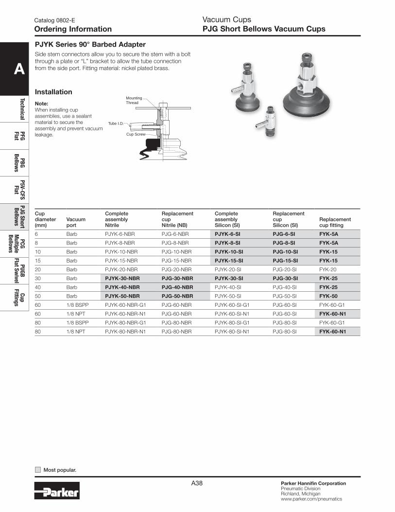
A
TechnicalPFG Flat
PBG Bellow
sP5V-CFS
FlatPJG Short Bellow
sPCG
Multiple
Bellows
PUGB Flat Sw
ivelCup
Fittings
Parker Hannifin CorporationPneumatic DivisionRichland, Michiganwww.parker.com/pneumatics
A38
Catalog 0802-E
Ordering InformationVacuum CupsPJG Short Bellows Vacuum Cups
Installation
PJYK Series 90° Barbed AdapterSide stem connectors allow you to secure the stem with a bolt through a plate or “L” bracket to allow the tube connection from the side port. Fitting material: nickel plated brass.
Tube I.D.
MountingThread
Cup Screw
Note:When installing cup assemblies, use a sealant material to secure the assembly and prevent vacuum leakage.
Cup diameter (mm)
Vacuumport
Complete assembly Nitrile
Replacement cup Nitrile (NB)
Complete assembly Silicon (SI)
Replacement cup Silicon (SI)
Replacement cup fitting
6 Barb PJYK-6-NBR PJG-6-NBR PJYK-6-SI PJG-6-SI FYK-5A
8 Barb PJYK-8-NBR PJG-8-NBR PJYK-8-SI PJG-8-SI FYK-5A
10 Barb PJYK-10-NBR PJG-10-NBR PJYK-10-SI PJG-10-SI FYK-15
15 Barb PJYK-15-NBR PJG-15-NBR PJYK-15-SI PJG-15-SI FYK-15
20 Barb PJYK-20-NBR PJG-20-NBR PJYK-20-SI PJG-20-SI FYK-20
30 Barb PJYK-30-NBR PJG-30-NBR PJYK-30-SI PJG-30-SI FYK-25
40 Barb PJYK-40-NBR PJG-40-NBR PJYK-40-SI PJG-40-SI FYK-25
50 Barb PJYK-50-NBR PJG-50-NBR PJYK-50-SI PJG-50-SI FYK-50
60 1/8 BSPP PJYK-60-NBR-G1 PJG-60-NBR PJYK-60-SI-G1 PJG-60-SI FYK-60-G1
60 1/8 NPT PJYK-60-NBR-N1 PJG-60-NBR PJYK-60-SI-N1 PJG-60-SI FYK-60-N1
80 1/8 BSPP PJYK-80-NBR-G1 PJG-80-NBR PJYK-80-SI-G1 PJG-80-SI FYK-60-G1
80 1/8 NPT PJYK-80-NBR-N1 PJG-80-NBR PJYK-80-SI-N1 PJG-80-SI FYK-60-N1
Most popular.
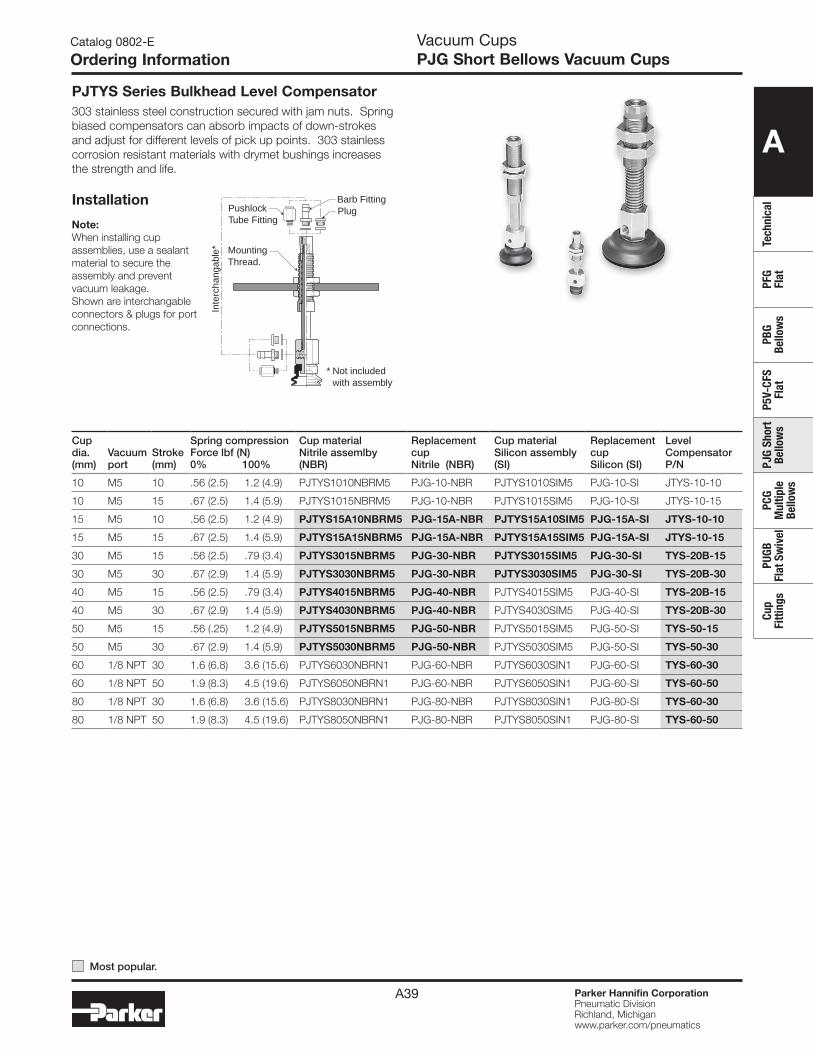
A
Tech
nica
lPF
G Fl
atPB
G Be
llow
sP5
V-CF
S Fl
atPJ
G Sh
ort
Bello
ws
PCG
Mul
tiple
Be
llow
s
PUGB
Fl
at S
wiv
elCu
p Fi
tting
s
Parker Hannifin CorporationPneumatic DivisionRichland, Michiganwww.parker.com/pneumatics
A39
PJTYS Series Bulkhead Level Compensator303 stainless steel construction secured with jam nuts. Spring biased compensators can absorb impacts of down-strokes and adjust for different levels of pick up points. 303 stainless corrosion resistant materials with drymet bushings increases the strength and life.
Catalog 0802-E
Ordering InformationVacuum CupsPJG Short Bellows Vacuum Cups
MountingThread.
Inte
rcha
ngab
le*
PlugPushlockTube Fitting
Barb Fitting
* Not included with assembly
Note:When installing cup assemblies, use a sealant material to secure the assembly and prevent vacuum leakage.Shown are interchangable connectors & plugs for port connections.
Installation
Cup dia. (mm)
Vacuumport
Stroke (mm)
Spring compression Force lbf (N)0% 100%
Cup material Nitrile assemlby (NBR)
Replacement cup Nitrile (NBR)
Cup material Silicon assembly (SI)
Replacement cup Silicon (SI)
Level Compensator P/N
10 M5 10 .56 (2.5) 1.2 (4.9) PJTYS1010NBRM5 PJG-10-NBR PJTYS1010SIM5 PJG-10-SI JTYS-10-10
10 M5 15 .67 (2.5) 1.4 (5.9) PJTYS1015NBRM5 PJG-10-NBR PJTYS1015SIM5 PJG-10-SI JTYS-10-15
15 M5 10 .56 (2.5) 1.2 (4.9) PJTYS15A10NBRM5 PJG-15A-NBR PJTYS15A10SIM5 PJG-15A-SI JTYS-10-10
15 M5 15 .67 (2.5) 1.4 (5.9) PJTYS15A15NBRM5 PJG-15A-NBR PJTYS15A15SIM5 PJG-15A-SI JTYS-10-15
30 M5 15 .56 (2.5) .79 (3.4) PJTYS3015NBRM5 PJG-30-NBR PJTYS3015SIM5 PJG-30-SI TYS-20B-15
30 M5 30 .67 (2.9) 1.4 (5.9) PJTYS3030NBRM5 PJG-30-NBR PJTYS3030SIM5 PJG-30-SI TYS-20B-30
40 M5 15 .56 (2.5) .79 (3.4) PJTYS4015NBRM5 PJG-40-NBR PJTYS4015SIM5 PJG-40-SI TYS-20B-15
40 M5 30 .67 (2.9) 1.4 (5.9) PJTYS4030NBRM5 PJG-40-NBR PJTYS4030SIM5 PJG-40-SI TYS-20B-30
50 M5 15 .56 (.25) 1.2 (4.9) PJTYS5015NBRM5 PJG-50-NBR PJTYS5015SIM5 PJG-50-SI TYS-50-15
50 M5 30 .67 (2.9) 1.4 (5.9) PJTYS5030NBRM5 PJG-50-NBR PJTYS5030SIM5 PJG-50-SI TYS-50-30
60 1/8 NPT 30 1.6 (6.8) 3.6 (15.6) PJTYS6030NBRN1 PJG-60-NBR PJTYS6030SIN1 PJG-60-SI TYS-60-30
60 1/8 NPT 50 1.9 (8.3) 4.5 (19.6) PJTYS6050NBRN1 PJG-60-NBR PJTYS6050SIN1 PJG-60-SI TYS-60-50
80 1/8 NPT 30 1.6 (6.8) 3.6 (15.6) PJTYS8030NBRN1 PJG-80-NBR PJTYS8030SIN1 PJG-80-SI TYS-60-30
80 1/8 NPT 50 1.9 (8.3) 4.5 (19.6) PJTYS8050NBRN1 PJG-80-NBR PJTYS8050SIN1 PJG-80-SI TYS-60-50
Most popular.
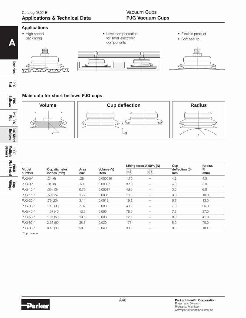
A
TechnicalPFG Flat
PBG Bellow
sP5V-CFS
FlatPJG Short Bellow
sPCG
Multiple
Bellows
PUGB Flat Sw
ivelCup
Fittings
Parker Hannifin CorporationPneumatic DivisionRichland, Michiganwww.parker.com/pneumatics
A40
Catalog 0802-E
Applications & Technical DataVacuum CupsPJG Vacuum Cups
Modelnumber
Cup diameterinches (mm)
Areacm2
Volume (V) liters
Lifting force @ 60% (N) Cupdeflection (S)mm
RadiusR(mm)
PJG-6-* .24 (6) .28 0.000016 1.70 — 4.2 4.0
PJG-8-* .31 (8) .50 0.00007 3.10 — 4.0 5.0
PJG-10-* .39 (10) 0.79 0.00017 4.80 — 3.0 6.0
PJG-15-* .59 (15) 1.77 0.0005 10.8 — 3.3 10.0
PJG-20-* .79 (20) 3.14 0.0012 19.2 — 5.5 13.0
PJG-30-* 1.18 (30) 7.07 0.003 43.2 — 7.0 26.0
PJG-40-* 1.57 (40) 12.6 0.005 76.9 — 7.2 37.0
PJG-50-* 1.97 (50) 19.6 0.008 120 — 9.0 41.0
PJG-60-* 2.36 (60) 28.3 0.020 173 — 8.0 70.0
PJG-80-* 3.15 (80) 50.3 0.040 308 — 9.5 100.0
*Cup material
Main data for short bellows PJG cups
S RV
Volume RadiusCup deflection
• High speed packaging
• Level compensation for small electronic components
• Flexible product• Soft seal lip
Applications
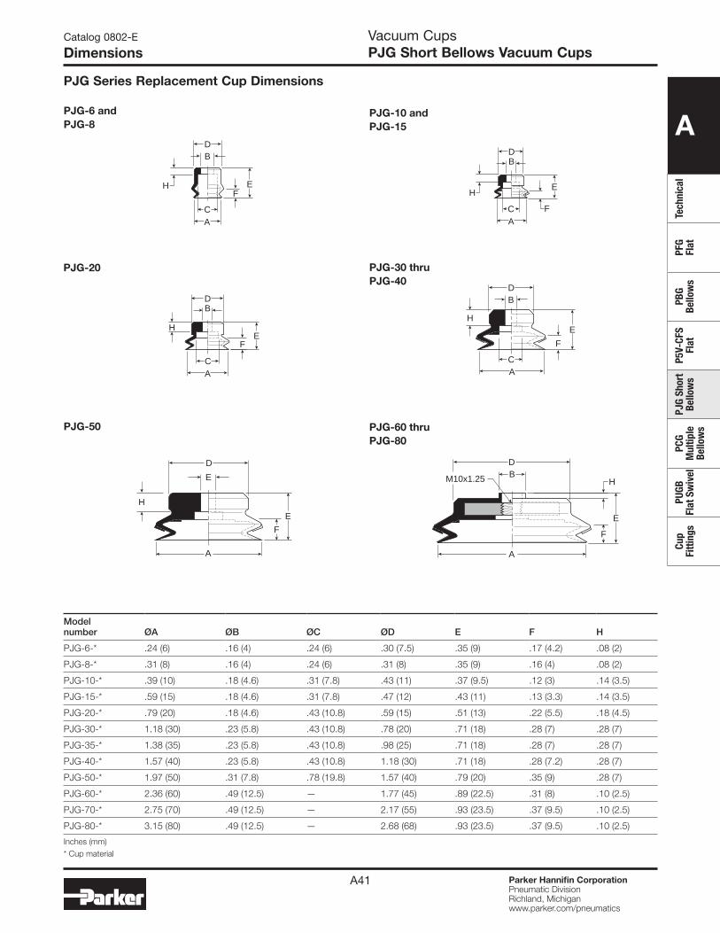
A
Tech
nica
lPF
G Fl
atPB
G Be
llow
sP5
V-CF
S Fl
atPJ
G Sh
ort
Bello
ws
PCG
Mul
tiple
Be
llow
s
PUGB
Fl
at S
wiv
elCu
p Fi
tting
s
Parker Hannifin CorporationPneumatic DivisionRichland, Michiganwww.parker.com/pneumatics
A41
Modelnumber ØA ØB ØC ØD E F H
PJG-6-* .24 (6) .16 (4) .24 (6) .30 (7.5) .35 (9) .17 (4.2) .08 (2)
PJG-8-* .31 (8) .16 (4) .24 (6) .31 (8) .35 (9) .16 (4) .08 (2)
PJG-10-* .39 (10) .18 (4.6) .31 (7.8) .43 (11) .37 (9.5) .12 (3) .14 (3.5)
PJG-15-* .59 (15) .18 (4.6) .31 (7.8) .47 (12) .43 (11) .13 (3.3) .14 (3.5)
PJG-20-* .79 (20) .18 (4.6) .43 (10.8) .59 (15) .51 (13) .22 (5.5) .18 (4.5)
PJG-30-* 1.18 (30) .23 (5.8) .43 (10.8) .78 (20) .71 (18) .28 (7) .28 (7)
PJG-35-* 1.38 (35) .23 (5.8) .43 (10.8) .98 (25) .71 (18) .28 (7) .28 (7)
PJG-40-* 1.57 (40) .23 (5.8) .43 (10.8) 1.18 (30) .71 (18) .28 (7.2) .28 (7)
PJG-50-* 1.97 (50) .31 (7.8) .78 (19.8) 1.57 (40) .79 (20) .35 (9) .28 (7)
PJG-60-* 2.36 (60) .49 (12.5) — 1.77 (45) .89 (22.5) .31 (8) .10 (2.5)
PJG-70-* 2.75 (70) .49 (12.5) — 2.17 (55) .93 (23.5) .37 (9.5) .10 (2.5)
PJG-80-* 3.15 (80) .49 (12.5) — 2.68 (68) .93 (23.5) .37 (9.5) .10 (2.5)
Inches (mm)* Cup material
Catalog 0802-E
Dimensions
PJG-6 andPJG-8
PJG-50 PJG-60 thruPJG-80
PJG-10 andPJG-15
A
D
F
E
HBM10x1.25
H
A
D
F
E
E
PJG-30 thruPJG-40
PJG-20
EF
AC
DB
H E
F
AC
DB
H
E
FAC
DB
HE
F
AC
DB
H
PJG Series Replacement Cup Dimensions
Vacuum CupsPJG Short Bellows Vacuum Cups
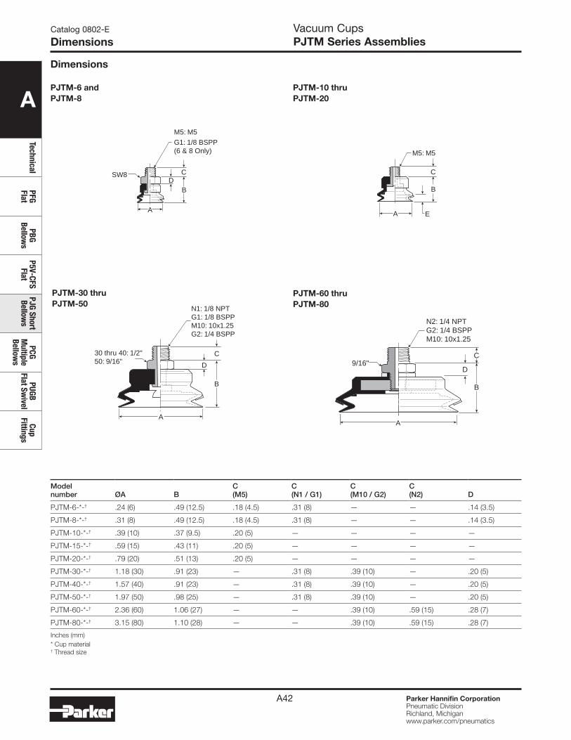
A
TechnicalPFG Flat
PBG Bellow
sP5V-CFS
FlatPJG Short Bellow
sPCG
Multiple
Bellows
PUGB Flat Sw
ivelCup
Fittings
Parker Hannifin CorporationPneumatic DivisionRichland, Michiganwww.parker.com/pneumatics
A42
PJTM-6 and PJTM-8
PJTM-30 thru PJTM-50
Modelnumber ØA B
C(M5)
C(N1 / G1)
C(M10 / G2)
C(N2) D
PJTM-6-*-† .24 (6) .49 (12.5) .18 (4.5) .31 (8) — — .14 (3.5)
PJTM-8-*-† .31 (8) .49 (12.5) .18 (4.5) .31 (8) — — .14 (3.5)
PJTM-10-*-† .39 (10) .37 (9.5) .20 (5) — — — —
PJTM-15-*-† .59 (15) .43 (11) .20 (5) — — — —
PJTM-20-*-† .79 (20) .51 (13) .20 (5) — — — —
PJTM-30-*-† 1.18 (30) .91 (23) — .31 (8) .39 (10) — .20 (5)
PJTM-40-*-† 1.57 (40) .91 (23) — .31 (8) .39 (10) — .20 (5)
PJTM-50-*-† 1.97 (50) .98 (25) — .31 (8) .39 (10) — .20 (5)
PJTM-60-*-† 2.36 (60) 1.06 (27) — — .39 (10) .59 (15) .28 (7)
PJTM-80-*-† 3.15 (80) 1.10 (28) — — .39 (10) .59 (15) .28 (7)
Inches (mm)* Cup material † Thread size
Catalog 0802-E
Dimensions
PJTM-60 thru PJTM-80
A
SW8
M5: M5
G1: 1/8 BSPP(6 & 8 Only)
B
CD
N1: 1/8 NPTG1: 1/8 BSPPM10: 10x1.25G2: 1/4 BSPP
30 thru 40: 1/2"50: 9/16"
A
B
C
D
B
C
D
N2: 1/4 NPTG2: 1/4 BSPPM10: 10x1.25
9/16"
A
PJTM-10 thru PJTM-20
EA
B
C
M5: M5
Vacuum CupsPJTM Series Assemblies
Dimensions
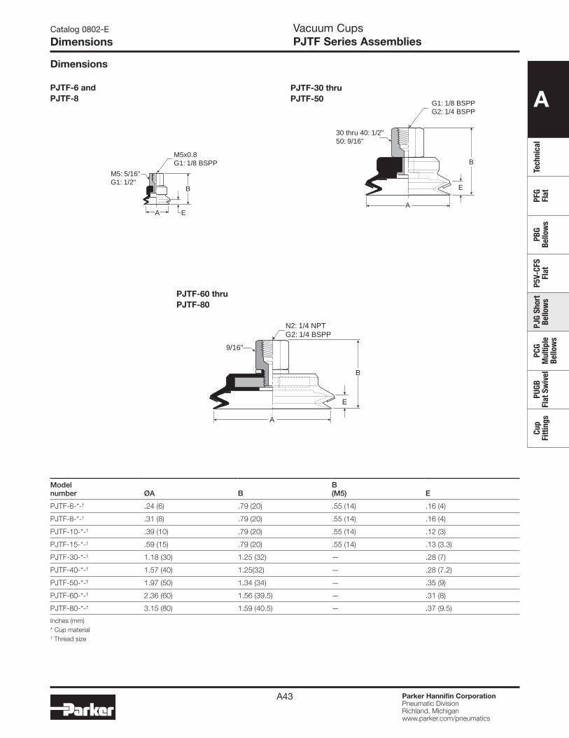
A
Tech
nica
lPF
G Fl
atPB
G Be
llow
sP5
V-CF
S Fl
atPJ
G Sh
ort
Bello
ws
PCG
Mul
tiple
Be
llow
s
PUGB
Fl
at S
wiv
elCu
p Fi
tting
s
Parker Hannifin CorporationPneumatic DivisionRichland, Michiganwww.parker.com/pneumatics
A43
Catalog 0802-E
Dimensions
PJTF-6 and PJTF-8
PJTF-60 thruPJTF-80
PJTF-30 thru PJTF-50
B
EA
M5x0.8G1: 1/8 BSPP
M5: 5/16"G1: 1/2"
A
B
E
N2: 1/4 NPTG2: 1/4 BSPP
9/16"
G1: 1/8 BSPPG2: 1/4 BSPP
30 thru 40: 1/2"50: 9/16"
E
B
A
Modelnumber ØA B
B(M5) E
PJTF-6-*-† .24 (6) .79 (20) .55 (14) .16 (4)
PJTF-8-*-† .31 (8) .79 (20) .55 (14) .16 (4)
PJTF-10-*-† .39 (10) .79 (20) .55 (14) .12 (3)
PJTF-15-*-† .59 (15) .79 (20) .55 (14) .13 (3.3)
PJTF-30-*-† 1.18 (30) 1.25 (32) — .28 (7)
PJTF-40-*-† 1.57 (40) 1.25(32) — .28 (7.2)
PJTF-50-*-† 1.97 (50) 1.34 (34) — .35 (9)
PJTF-60-*-† 2.36 (60) 1.56 (39.5) — .31 (8)
PJTF-80-*-† 3.15 (80) 1.59 (40.5) — .37 (9.5)
Inches (mm)* Cup material† Thread size
Vacuum CupsPJTF Series Assemblies
Dimensions

A
TechnicalPFG Flat
PBG Bellow
sP5V-CFS
FlatPJG Short Bellow
sPCG
Multiple
Bellows
PUGB Flat Sw
ivelCup
Fittings
Parker Hannifin CorporationPneumatic DivisionRichland, Michiganwww.parker.com/pneumatics
A44
Catalog 0802-E
Dimensions
PJTK-6 and PJTK-8
PJTK-30 thru PJTK-50
Modelnumber ØA B C D E F G
Wtoz (g)
PJTK-6-* .24 (6) 1.30 (33) .39 (10) .55 (14) .17 (4.2) .47 (12) .12 (3) .4 (11)
PJTK-8-* .31 (8) 1.30 (33) .39 (10) .55 (14) .16 (4) .47 (12) .12 (3) .4 (11)
PJTK-10-* .39 (10) 1.87 (47.5) .63 (16) .87 (22) .12 (3) .59 (15) .12 (3) .5 (14)
PJTK-15-* .59 (15) 1.93 (49) .63 (16) .87 (22) .13 (3.3) .59 (15) .12 (3) .5 (15)
PJTK-20-* .79 (20) 2.01 (51) .63 (16) .87 (22) .22 (5.5) .59 (15) .20 (5) .6 (17)
PJTK-30-* 1.18 (30) 2.60 (66) .63 (16) 1.26 (32) .28 (7) .79 (20) .20 (5) 1.5 (42)
PJTK-40-* 1.57 (40) 2.60 (66) .63 (16) 1.26 (32) .28 (7.2) .79 (20) .20 (5) 1.6 (44)
PJTK-50-* 1.97 (50) 2.68 (68) .63 (16) 1.26 (32) .35 (9) .79 (20) .20 (5) 25.0 (58)
PJTK-60-*-† 2.36 (60) 2.46 (62.5) — 1.67 (42.5) .31 (8) .79 (20) .24 (6) 5.1 (144)
PJTK-80-*-† 3.15 (80) 2.50 (63.5) — 1.67 (42.5) .37 (9.5) .79 (20) .24 (6) 6.7 (190)
Inches (mm)* Cup material † Vacuum port
PJTK-60 thruPJTK-80
EA
.197 Dia.Ø (5)
.098 Dia.Ø (2.5)
FG
C
D B
M9x1.0
SW12
A
B
FG
C
D
E
M10x1.5
SW14
.197 Dia.Ø (5) .118 Dia.
Ø (3)
M5x0.8
N1: 1/8 NPTG1: 1/8 BSPP
SW21
M16x1.5
B
FG
D
E
A
Dimensions
PJTK-10 thru PJTK-20
EA
.197 Dia.Ø (5) .098 Dia.
Ø (2.5)
FG
C
D B
M8x1.25
SW12
Vacuum CupsPJTK Series Assemblies
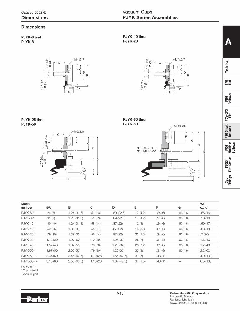
A
Tech
nica
lPF
G Fl
atPB
G Be
llow
sP5
V-CF
S Fl
atPJ
G Sh
ort
Bello
ws
PCG
Mul
tiple
Be
llow
s
PUGB
Fl
at S
wiv
elCu
p Fi
tting
s
Parker Hannifin CorporationPneumatic DivisionRichland, Michiganwww.parker.com/pneumatics
A45
Catalog 0802-E
Dimensions
PJYK-60 thru PJYK-80
PJYK-6 and PJYK-8
PJYK-25 thru PJYK-50
Modelnumber ØA B C D E F G
Wtoz (g)
PJYK-6-* .24 (6) 1.24 (31.5) .51 (13) .89 (22.5) .17 (4.2) .24 (6) .63 (16) .56 (16)
PJYK-8-* .31 (8) 1.24 (31.5) .51 (13) .89 (22.5) .17 (4.2) .24 (6) .63 (16) .56 (16)
PJYK-10-* .39 (10) 1.24 (31.5) .55 (14) .87 (22) .12 (3) .24 (6) .63 (16) .59 (17)
PJYK-15-* .59 (15) 1.30 (33) .55 (14) .87 (22) .13 (3.3) .24 (6) .63 (16) .63 (18)
PJYK-20-* .79 (20) 1.38 (35) .55 (14) .87 (22) .22 (5.5) .24 (6) .63 (16) .7 (20)
PJYK-30-* 1.18 (30) 1.97 (50) .79 (20) 1.26 (32) .28 (7) .31 (8) .63 (16) 1.6 (46)
PJYK-40-* 1.57 (40) 1.97 (50) .79 (20) 1.26 (32) .28 (7.2) .31 (8) .63 (16) 1.7 (48)
PJYK-50-* 1.97 (50) 2.05 (52) .79 (20) 1.26 (32) .35 (9) .31 (8) .63 (16) 2.2 (62)
PJYK-60-*-† 2.36 (60) 2.46 (62.5) 1.10 (28) 1.67 (42.5) .31 (8) .43 (11) — 4.9 (139)
PJYK-80-*-† 3.15 (80) 2.50 (63.5) 1.10 (28) 1.67 (42.5) .37 (9.5) .43 (11) — 6.5 (185)
Inches (mm)* Cup material† Vacuum port
FC
DB
E.197
Dia
.Ø
(5)
.118
Dia
.Ø
(3)
M4x0.7G
A
B
F
G
C
D
E
.197
Dia
.Ø
(5)
.118
Dia
.Ø
(3)
A
M6x1.0
B
F
N1: 1/8 NPTG1: 1/8 BSPP
C
D
E
A
M8x1.25
PJYK-10 thru PJYK-20
FC
DB
E.197
Dia
.Ø
(5)
.118
Dia
.Ø
(3) G
A
M4x0.7
Vacuum CupsPJYK Series Assemblies
Dimensions
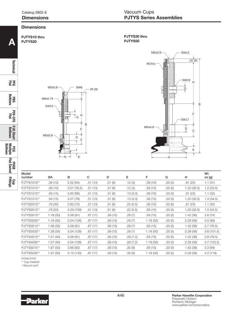
A
TechnicalPFG Flat
PBG Bellow
sP5V-CFS
FlatPJG Short Bellow
sPCG
Multiple
Bellows
PUGB Flat Sw
ivelCup
Fittings
Parker Hannifin CorporationPneumatic DivisionRichland, Michiganwww.parker.com/pneumatics
A46
Catalog 0802-E
Dimensions
Modelnumber ØA B C D E F G H
Wtoz (g)
PJTYS1010*† .39 (10) 2.52 (64) .51 (13) .31 (8) .12 (3) .39 (10) .20 (5) .91 (23) 1.1 (31)
PJTYS1015*† .39 (10) 3.01 (76.5) .51 (13) .31 (8) .12 (3) .59 (15) .20 (5) 1.20 (30.5) 1.2 (33.5)
PJTYS1510*† .59 (15) 2.60 (66) .51 (13) .31 (8) .13 (3.3) .39 (10) .20 (5) .91 (23) 1.1 (32)
PJTYS1515*† .59 (15) 3.07 (78) .51 (13) .31 (8) .13 (3.3) .59 (15) .20 (5) 1.20 (30.5) 1.3 (34.5)
PJTYS2010*† .79 (20) 2.83 (72) .51 (13) .31 (8) .22 (5.5) .39 (10) .20 (5) .91 (23) 1.1 (32)
PJTYS2015*† .79 (20) 4.29 (109) .51 (13) .31 (8) .22 (5.5) .59 (15) .20 (5) 1.20 (30.5) 1.3 (34.5)
PJTYS3015*† 1.18 (30) 3.58 (91) .67 (17) .39 (10) .28 (7) .59 (15) .20 (5) 1.42 (36) 2.6 (74)
PJTYS3030*† 1.18 (30) 5.04 (128) .67 (17) .39 (10) .28 (7) 1.18 (30) .20 (5) 2.28 (58) 3.5 (99)
PJTYS3515*† 1.38 (35) 3.58 (91) .67 (17) .39 (10) .28 (7) .59 (15) .20 (5) 1.42 (36) 2.7 (76.5)
PJTYS3530*† 1.38 (35) 5.04 (128) .67 (17) .39 (10) .28 (7) 1.18 (30) .20 (5) 2.28 (58) 3.6 (101.5)
PJTYS4015*† 1.57 (40) 3.58 (91) .67 (17) .39 (10) .28 (7.2) .59 (15) .20 (5) 1.42 (36) 2.8 (78.5)
PJTYS4030*† 1.57 (40) 5.04 (128) .67 (17) .39 (10) .28 (7.2) 1.18 (30) .20 (5) 2.28 (58) 3.7 (103.5)
PJTYS5015*† 1.97 (50) 3.66 (93) .67 (17) .39 (10) .35 (9) .59 (15) .20 (5) 1.42 (36) 3.3 (94)
PJTYS5030*† 1.97 (50) 5.12 (130) .67 (17) .39 (10) .35 (9) 1.18 (30) .20 (5) 2.28 (58) 4.2 (119)
Inches (mm)** Cup material † Vacuum port
PJTYS10 thruPJTYS20
M5x0.8
M5x0.8
SW6.35 (9)
SW12
M8x0.75
B
DC
F
HG
EA
Vacuum CupsPJTYS Series Assemblies
Dimensions
PJTYS30 thruPJTYS50
M5x0.8
M5x0.8
SW12
SW19
SW17
M14x1
B
D
E
C
H
.20 (5)
F
G
A
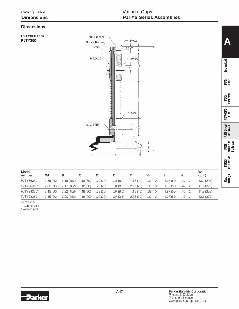
A
Tech
nica
lPF
G Fl
atPB
G Be
llow
sP5
V-CF
S Fl
atPJ
G Sh
ort
Bello
ws
PCG
Mul
tiple
Be
llow
s
PUGB
Fl
at S
wiv
elCu
p Fi
tting
s
Parker Hannifin CorporationPneumatic DivisionRichland, Michiganwww.parker.com/pneumatics
A47
Vacuum CupsPJTYS Series Assemblies
Dimensions
Catalog 0802-E
Dimensions
Modelnumber ØA B C D E F G H J
Wtoz (g)
PJTYS6030*† 2.36 (60) 6.18 (157) 1.18 (30) .79 (20) .31 (8) 1.18 (45) .39 (10) 1.97 (50) .47 (12) 10.4 (294)
PJTYS6050*† 2.36 (60) 7.17 (182) 1.18 (30) .79 (20) .31 (8) 2.76 (70) .39 (10) 1.97 (50) .47 (12) 11.6 (328)
PJTYS8030*† 3.15 (80) 6.22 (158) 1.18 (30) .79 (20) .37 (9.5) 1.18 (45) .39 (10) 1.97 (50) .47 (12) 11.9 (338)
PJTYS8050*† 3.15 (80) 7.20 (183) 1.18 (30) .79 (20) .37 (9.5) 2.76 (70) .39 (10) 1.97 (50) .47 (12) 13.1 (372)
Inches (mm)** Cup material † Vacuum port
PJTYS60 thruPJTYS80
N1: 1/8 NPT
N1: 1/8 NPT
SW19
SW30
SW24
M22x1.5
B
D
E
C
H
J.28 (7)
F
G
A
Shock Pad
5mm
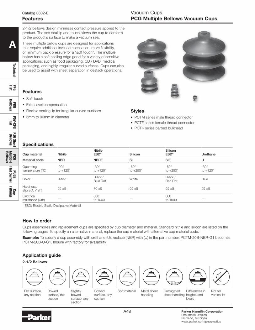
A
TechnicalPFG Flat
PBG Bellow
sP5V-CFS
FlatPJG Short Bellow
sPCG
Multiple
Bellows
PUGB Flat Sw
ivelCup
Fittings
Parker Hannifin CorporationPneumatic DivisionRichland, Michiganwww.parker.com/pneumatics
A48
Catalog 0802-E
FeaturesVacuum CupsPCG Multiple Bellows Vacuum Cups
Features• Soft touch
• Extra level compensation
• Flexible sealing lip for irregular curved surfaces
• 5mm to 90mm in diameter
Specifications
Cup material NitrileNitrileESD* Silicon
SiliconESD* Urethane
Material code NBR NBRE SI SIE U
Operating temperature (°C)
-20° to +120°
-30° to +120°
-60° to +250°
-60° to +250°
-30° to +120°
Color Black Black / Blue Dot White Black /
Red Dot Blue
Hardness, shore A (°Sh) 55 ±5 70 ±5 55 ±5 55 ±5 55 ±5
Electrical resistance (Ωm) — 800
to 1000 — 800 to 1000 —
* ESD: Electric Static Dissipative Material
2-1/2 bellows design minimizes contact pressure applied to the product. The soft seal lip and touch allows the cup to conform to the product’s surface to make a vacuum seal.
These multiple bellow cups are designed for applications that require additional level compensation, more flexibility, or minimum back pressure for a “soft touch”. The multiple bellow has a soft sealing edge good for a variety of sensitive applications; such as food packaging, CD / DVD, medical packaging, and highly irregular curved surfaces. Cups can also be used to assist with sheet separation in destack operations.
Styles• PCTM series male thread connector• PCTF series female thread connector• PCTK series barbed bulkhead
How to orderCups assemblies and replacement cups are specified by cup diameter and material. Standard nitrile and silicon are listed on the following pages. To specify an alternative material, replace the cup material with alternative cup material code.
Example: To specify a cup assembly with urethane (U), replace (NBR) with (U) in the part number. PCTM-20B-NBR-G1 becomes PCTM-20B-U-G1. Inquire with factory for availability.
Application guide2-1/2 Bellows
Flat surface, any section
Bowed surface, thin section
Slightly bowed surface, any section
Bowed surface, any section
Soft material Metal sheet handling
Corrugated sheet handling
Differences in heights and levels
Not for vertical lift
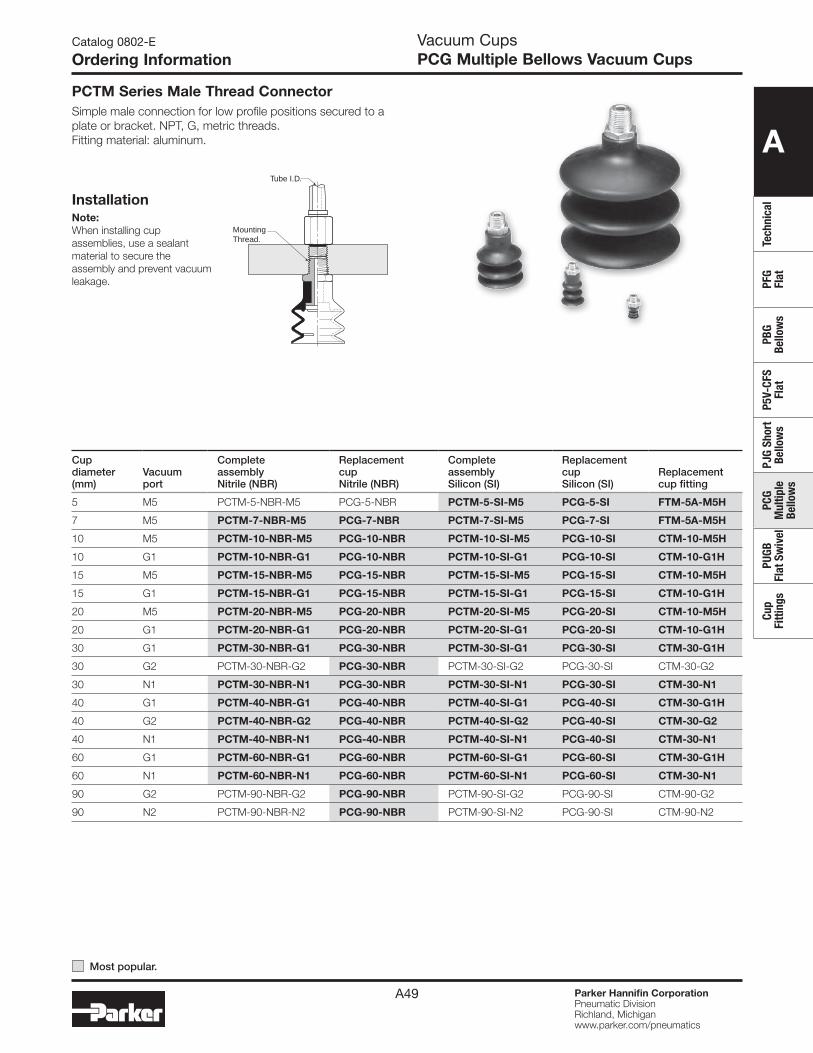
A
Tech
nica
lPF
G Fl
atPB
G Be
llow
sP5
V-CF
S Fl
atPJ
G Sh
ort
Bello
ws
PCG
Mul
tiple
Be
llow
s
PUGB
Fl
at S
wiv
elCu
p Fi
tting
s
Parker Hannifin CorporationPneumatic DivisionRichland, Michiganwww.parker.com/pneumatics
A49
Vacuum CupsPCG Multiple Bellows Vacuum Cups
Catalog 0802-E
Ordering Information
Tube I.D.
MountingThread.
Note:When installing cup assemblies, use a sealant material to secure the assembly and prevent vacuum leakage.
PCTM Series Male Thread ConnectorSimple male connection for low profile positions secured to a plate or bracket. NPT, G, metric threads. Fitting material: aluminum.
Installation
Cup diameter (mm)
Vacuumport
Complete assembly Nitrile (NBR)
Replacement cup Nitrile (NBR)
Complete assembly Silicon (SI)
Replacement cup Silicon (SI)
Replacement cup fitting
5 M5 PCTM-5-NBR-M5 PCG-5-NBR PCTM-5-SI-M5 PCG-5-SI FTM-5A-M5H
7 M5 PCTM-7-NBR-M5 PCG-7-NBR PCTM-7-SI-M5 PCG-7-SI FTM-5A-M5H
10 M5 PCTM-10-NBR-M5 PCG-10-NBR PCTM-10-SI-M5 PCG-10-SI CTM-10-M5H
10 G1 PCTM-10-NBR-G1 PCG-10-NBR PCTM-10-SI-G1 PCG-10-SI CTM-10-G1H
15 M5 PCTM-15-NBR-M5 PCG-15-NBR PCTM-15-SI-M5 PCG-15-SI CTM-10-M5H
15 G1 PCTM-15-NBR-G1 PCG-15-NBR PCTM-15-SI-G1 PCG-15-SI CTM-10-G1H
20 M5 PCTM-20-NBR-M5 PCG-20-NBR PCTM-20-SI-M5 PCG-20-SI CTM-10-M5H
20 G1 PCTM-20-NBR-G1 PCG-20-NBR PCTM-20-SI-G1 PCG-20-SI CTM-10-G1H
30 G1 PCTM-30-NBR-G1 PCG-30-NBR PCTM-30-SI-G1 PCG-30-SI CTM-30-G1H
30 G2 PCTM-30-NBR-G2 PCG-30-NBR PCTM-30-SI-G2 PCG-30-SI CTM-30-G2
30 N1 PCTM-30-NBR-N1 PCG-30-NBR PCTM-30-SI-N1 PCG-30-SI CTM-30-N1
40 G1 PCTM-40-NBR-G1 PCG-40-NBR PCTM-40-SI-G1 PCG-40-SI CTM-30-G1H
40 G2 PCTM-40-NBR-G2 PCG-40-NBR PCTM-40-SI-G2 PCG-40-SI CTM-30-G2
40 N1 PCTM-40-NBR-N1 PCG-40-NBR PCTM-40-SI-N1 PCG-40-SI CTM-30-N1
60 G1 PCTM-60-NBR-G1 PCG-60-NBR PCTM-60-SI-G1 PCG-60-SI CTM-30-G1H
60 N1 PCTM-60-NBR-N1 PCG-60-NBR PCTM-60-SI-N1 PCG-60-SI CTM-30-N1
90 G2 PCTM-90-NBR-G2 PCG-90-NBR PCTM-90-SI-G2 PCG-90-SI CTM-90-G2
90 N2 PCTM-90-NBR-N2 PCG-90-NBR PCTM-90-SI-N2 PCG-90-SI CTM-90-N2
Most popular.
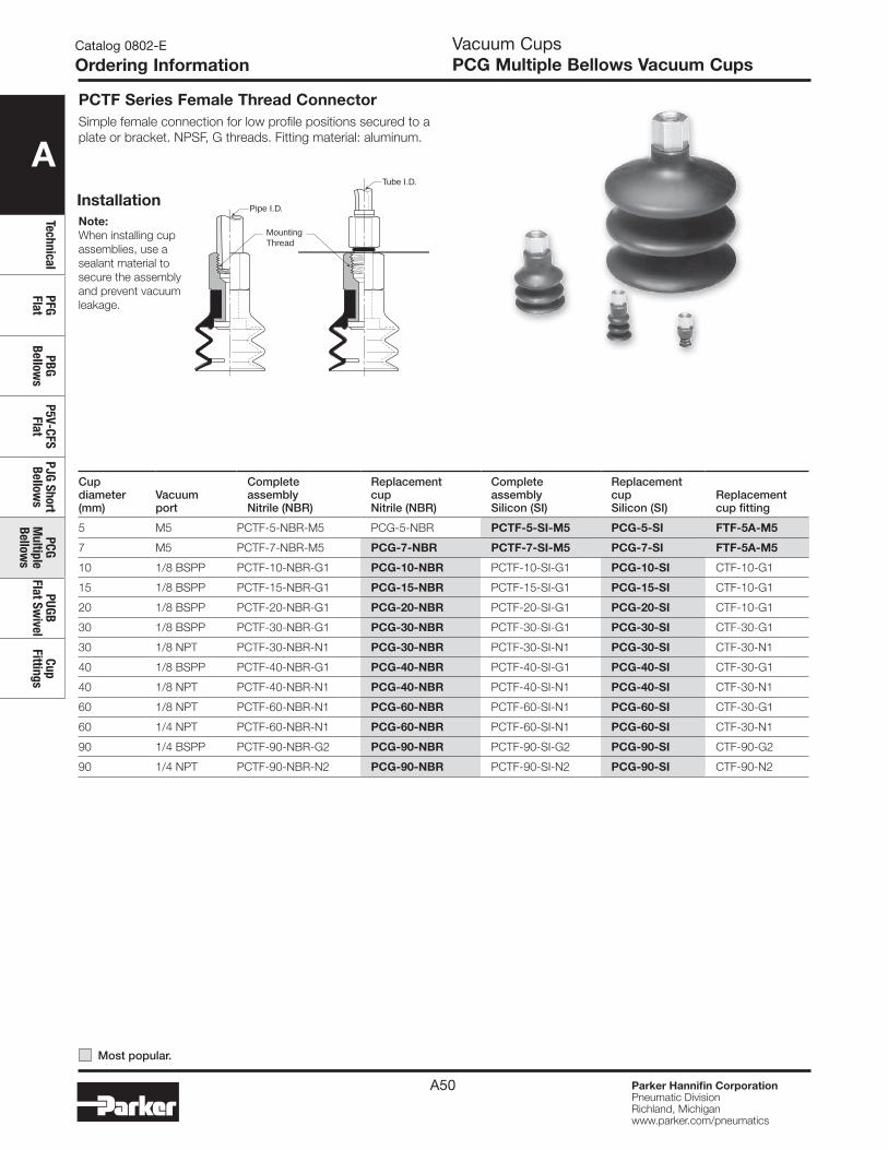
A
TechnicalPFG Flat
PBG Bellow
sP5V-CFS
FlatPJG Short Bellow
sPCG
Multiple
Bellows
PUGB Flat Sw
ivelCup
Fittings
Parker Hannifin CorporationPneumatic DivisionRichland, Michiganwww.parker.com/pneumatics
A50
Vacuum CupsPCG Multiple Bellows Vacuum Cups
Catalog 0802-E
Ordering Information
PCTF Series Female Thread ConnectorSimple female connection for low profile positions secured to a plate or bracket. NPSF, G threads. Fitting material: aluminum.
InstallationTube I.D.
Pipe I.D.
MountingThread
Note:When installing cup assemblies, use a sealant material to secure the assembly and prevent vacuum leakage.
Cup diameter (mm)
Vacuumport
Complete assembly Nitrile (NBR)
Replacement cup Nitrile (NBR)
Complete assembly Silicon (SI)
Replacement cup Silicon (SI)
Replacement cup fitting
5 M5 PCTF-5-NBR-M5 PCG-5-NBR PCTF-5-SI-M5 PCG-5-SI FTF-5A-M5
7 M5 PCTF-7-NBR-M5 PCG-7-NBR PCTF-7-SI-M5 PCG-7-SI FTF-5A-M5
10 1/8 BSPP PCTF-10-NBR-G1 PCG-10-NBR PCTF-10-SI-G1 PCG-10-SI CTF-10-G1
15 1/8 BSPP PCTF-15-NBR-G1 PCG-15-NBR PCTF-15-SI-G1 PCG-15-SI CTF-10-G1
20 1/8 BSPP PCTF-20-NBR-G1 PCG-20-NBR PCTF-20-SI-G1 PCG-20-SI CTF-10-G1
30 1/8 BSPP PCTF-30-NBR-G1 PCG-30-NBR PCTF-30-SI-G1 PCG-30-SI CTF-30-G1
30 1/8 NPT PCTF-30-NBR-N1 PCG-30-NBR PCTF-30-SI-N1 PCG-30-SI CTF-30-N1
40 1/8 BSPP PCTF-40-NBR-G1 PCG-40-NBR PCTF-40-SI-G1 PCG-40-SI CTF-30-G1
40 1/8 NPT PCTF-40-NBR-N1 PCG-40-NBR PCTF-40-SI-N1 PCG-40-SI CTF-30-N1
60 1/8 NPT PCTF-60-NBR-N1 PCG-60-NBR PCTF-60-SI-N1 PCG-60-SI CTF-30-G1
60 1/4 NPT PCTF-60-NBR-N1 PCG-60-NBR PCTF-60-SI-N1 PCG-60-SI CTF-30-N1
90 1/4 BSPP PCTF-90-NBR-G2 PCG-90-NBR PCTF-90-SI-G2 PCG-90-SI CTF-90-G2
90 1/4 NPT PCTF-90-NBR-N2 PCG-90-NBR PCTF-90-SI-N2 PCG-90-SI CTF-90-N2
Most popular.
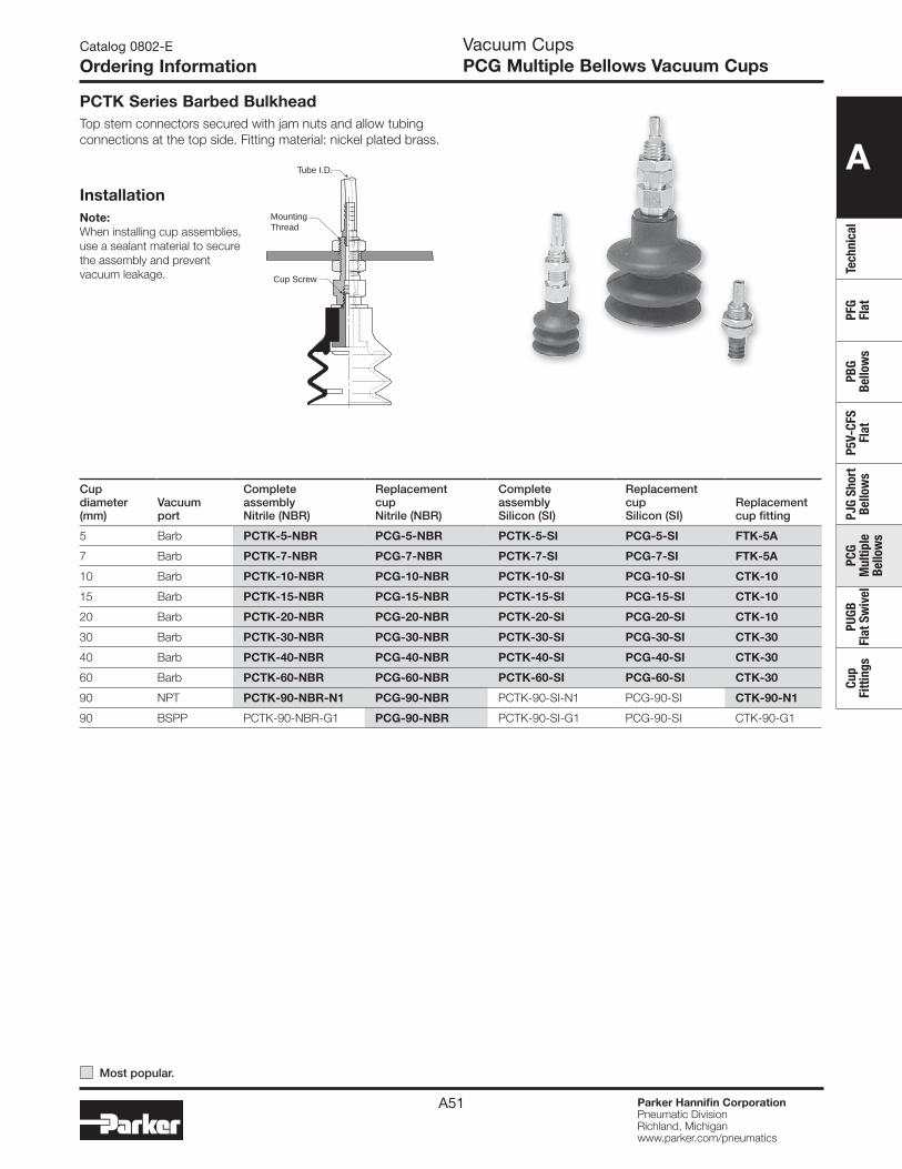
A
Tech
nica
lPF
G Fl
atPB
G Be
llow
sP5
V-CF
S Fl
atPJ
G Sh
ort
Bello
ws
PCG
Mul
tiple
Be
llow
s
PUGB
Fl
at S
wiv
elCu
p Fi
tting
s
Parker Hannifin CorporationPneumatic DivisionRichland, Michiganwww.parker.com/pneumatics
A51
Vacuum CupsPCG Multiple Bellows Vacuum Cups
Catalog 0802-E
Ordering Information
PCTK Series Barbed BulkheadTop stem connectors secured with jam nuts and allow tubing connections at the top side. Fitting material: nickel plated brass.
Installation
Tube I.D.
MountingThread
Cup Screw
Note:When installing cup assemblies, use a sealant material to secure the assembly and prevent vacuum leakage.
Cup diameter (mm)
Vacuumport
Complete assembly Nitrile (NBR)
Replacement cup Nitrile (NBR)
Complete assembly Silicon (SI)
Replacement cup Silicon (SI)
Replacement cup fitting
5 Barb PCTK-5-NBR PCG-5-NBR PCTK-5-SI PCG-5-SI FTK-5A
7 Barb PCTK-7-NBR PCG-7-NBR PCTK-7-SI PCG-7-SI FTK-5A
10 Barb PCTK-10-NBR PCG-10-NBR PCTK-10-SI PCG-10-SI CTK-10
15 Barb PCTK-15-NBR PCG-15-NBR PCTK-15-SI PCG-15-SI CTK-10
20 Barb PCTK-20-NBR PCG-20-NBR PCTK-20-SI PCG-20-SI CTK-10
30 Barb PCTK-30-NBR PCG-30-NBR PCTK-30-SI PCG-30-SI CTK-30
40 Barb PCTK-40-NBR PCG-40-NBR PCTK-40-SI PCG-40-SI CTK-30
60 Barb PCTK-60-NBR PCG-60-NBR PCTK-60-SI PCG-60-SI CTK-30
90 NPT PCTK-90-NBR-N1 PCG-90-NBR PCTK-90-SI-N1 PCG-90-SI CTK-90-N1
90 BSPP PCTK-90-NBR-G1 PCG-90-NBR PCTK-90-SI-G1 PCG-90-SI CTK-90-G1
Most popular.
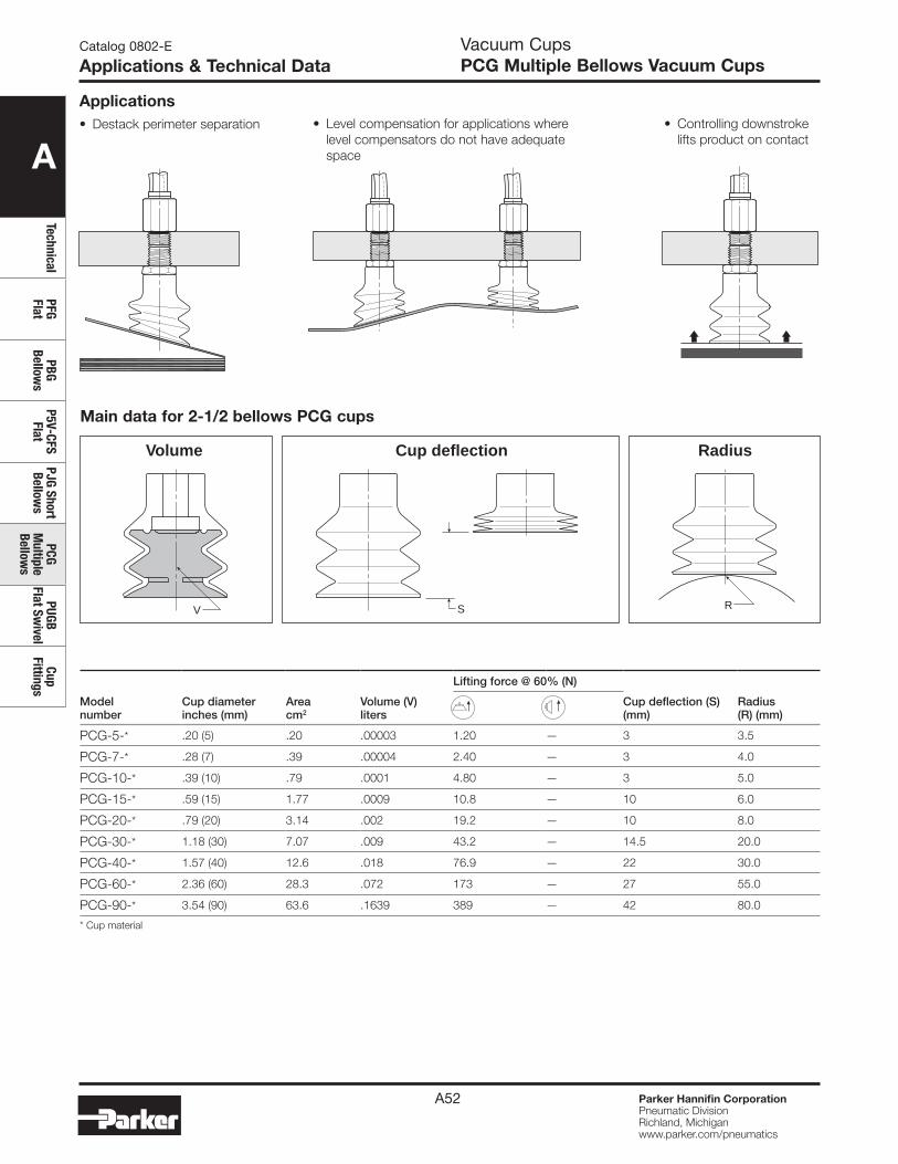
A
TechnicalPFG Flat
PBG Bellow
sP5V-CFS
FlatPJG Short Bellow
sPCG
Multiple
Bellows
PUGB Flat Sw
ivelCup
Fittings
Parker Hannifin CorporationPneumatic DivisionRichland, Michiganwww.parker.com/pneumatics
A52
Catalog 0802-E
Applications & Technical Data
Modelnumber
Cup diameter inches (mm)
Areacm2
Volume (V) liters
Lifting force @ 60% (N)
Cup deflection (S) (mm)
Radius(R) (mm)
PCG-5-* .20 (5) .20 .00003 1.20 — 3 3.5
PCG-7-* .28 (7) .39 .00004 2.40 — 3 4.0
PCG-10-* .39 (10) .79 .0001 4.80 — 3 5.0
PCG-15-* .59 (15) 1.77 .0009 10.8 — 10 6.0
PCG-20-* .79 (20) 3.14 .002 19.2 — 10 8.0
PCG-30-* 1.18 (30) 7.07 .009 43.2 — 14.5 20.0
PCG-40-* 1.57 (40) 12.6 .018 76.9 — 22 30.0
PCG-60-* 2.36 (60) 28.3 .072 173 — 27 55.0
PCG-90-* 3.54 (90) 63.6 .1639 389 — 42 80.0
* Cup material
Main data for 2-1/2 bellows PCG cups
S RV
Volume RadiusCup deflection
• Destack perimeter separation • Controlling downstroke lifts product on contact
• Level compensation for applications where level compensators do not have adequate space
Vacuum CupsPCG Multiple Bellows Vacuum Cups
Applications
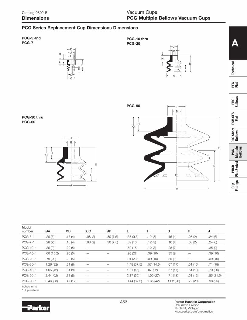
A
Tech
nica
lPF
G Fl
atPB
G Be
llow
sP5
V-CF
S Fl
atPJ
G Sh
ort
Bello
ws
PCG
Mul
tiple
Be
llow
s
PUGB
Fl
at S
wiv
elCu
p Fi
tting
s
Parker Hannifin CorporationPneumatic DivisionRichland, Michiganwww.parker.com/pneumatics
A53
Modelnumber ØA ØB ØC ØD E F G H J
PCG-5-* .20 (5) .16 (4) .08 (2) .30 (7.5) .37 (9.5) .12 (3) .16 (4) .08 (2) .24 (6)
PCG-7-* .28 (7) .16 (4) .08 (2) .30 (7.5) .39 (10) .12 (3) .16 (4) .08 (2) .24 (6)
PCG-10-* .35 (9) .20 (5) — — .59 (15) .12 (3) .28 (7) — .35 (9)
PCG-15-* .60 (15.2) .20 (5) — — .90 (22) .39 (10) .35 (9) — .39 (10)
PCG-20-* .79 (20) .20 (5) — — .91 (23) .39 (10) .35 (9) — .39 (10)
PCG-30-* 1.26 (32) .31 (8) — — 1.48 (37.5) .57 (14.5) .67 (17) .51 (13) .71 (18)
PCG-40-* 1.65 (42) .31 (8) — — 1.81 (46) .87 (22) .67 (17) .51 (13) .79 (20)
PCG-60-* 2.44 (62) .31 (8) — — 2.17 (55) 1.06 (27) .71 (18) .51 (13) .85 (21.5)
PCG-90-* 3.46 (88) .47 (12) — — 3.44 (87.5) 1.65 (42) 1.02 (26) .79 (20) .98 (25)
Inches (mm)* Cup material
Catalog 0802-E
Dimensions
PCG-5 andPCG-7
PCG-10 thruPCG-20
PCG-30 thruPCG-60
PCG-90
A
E
F
BJ
HG
EF
DJ
CA
B
G
H
A
E
F
BJ
H
A
E
F
HG
B
J
PCG Series Replacement Cup Dimensions Dimensions
Vacuum CupsPCG Multiple Bellows Vacuum Cups
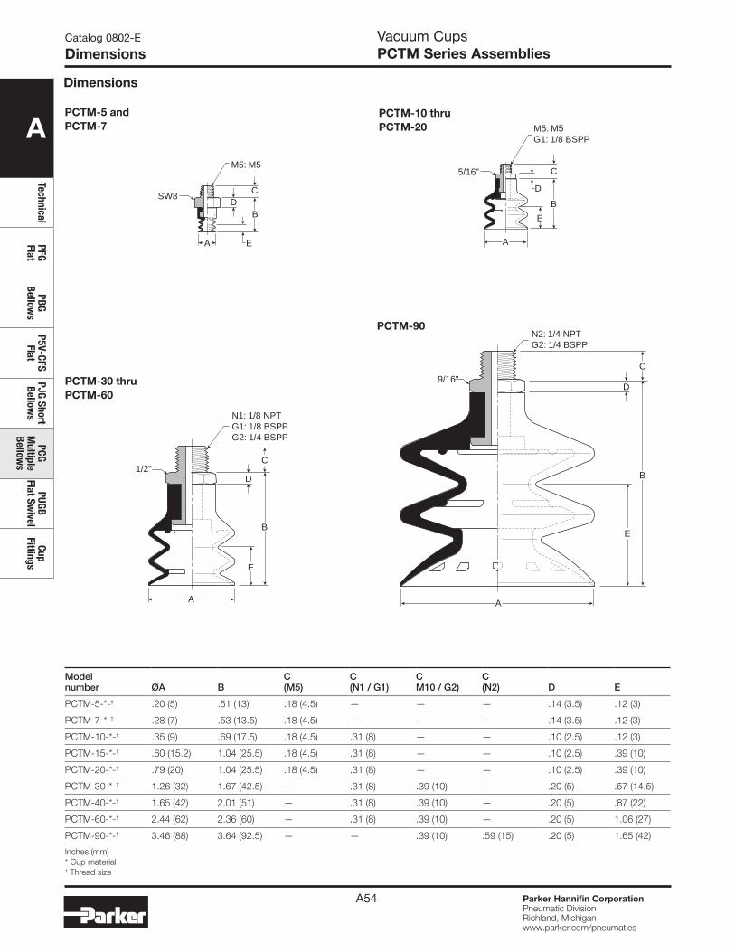
A
TechnicalPFG Flat
PBG Bellow
sP5V-CFS
FlatPJG Short Bellow
sPCG
Multiple
Bellows
PUGB Flat Sw
ivelCup
Fittings
Parker Hannifin CorporationPneumatic DivisionRichland, Michiganwww.parker.com/pneumatics
A54
SW8
M5: M5
E
B
CD
A A
B
E
C
D
5/16"
M5: M5G1: 1/8 BSPP
PCTM-5 and PCTM-7
PCTM-10 thru PCTM-20
Modelnumber ØA B
C(M5)
C(N1 / G1)
CM10 / G2)
C(N2) D E
PCTM-5-*-† .20 (5) .51 (13) .18 (4.5) — — — .14 (3.5) .12 (3)
PCTM-7-*-† .28 (7) .53 (13.5) .18 (4.5) — — — .14 (3.5) .12 (3)
PCTM-10-*-† .35 (9) .69 (17.5) .18 (4.5) .31 (8) — — .10 (2.5) .12 (3)
PCTM-15-*-† .60 (15.2) 1.04 (25.5) .18 (4.5) .31 (8) — — .10 (2.5) .39 (10)
PCTM-20-*-† .79 (20) 1.04 (25.5) .18 (4.5) .31 (8) — — .10 (2.5) .39 (10)
PCTM-30-*-† 1.26 (32) 1.67 (42.5) — .31 (8) .39 (10) — .20 (5) .57 (14.5)
PCTM-40-*-† 1.65 (42) 2.01 (51) — .31 (8) .39 (10) — .20 (5) .87 (22)
PCTM-60-*-† 2.44 (62) 2.36 (60) — .31 (8) .39 (10) — .20 (5) 1.06 (27)
PCTM-90-*-† 3.46 (88) 3.64 (92.5) — — .39 (10) .59 (15) .20 (5) 1.65 (42)
Inches (mm)* Cup material† Thread size
Catalog 0802-E
Dimensions
PCTM-90
PCTM-30 thru PCTM-60
A
B
E
N1: 1/8 NPTG1: 1/8 BSPPG2: 1/4 BSPP
1/2"C
D B
E
N2: 1/4 NPTG2: 1/4 BSPP
9/16"C
D
A
Dimensions
Vacuum CupsPCTM Series Assemblies
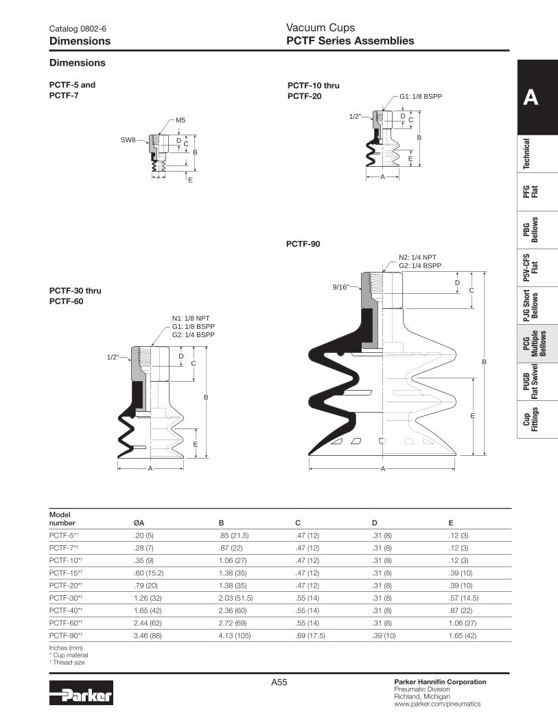
A
Tech
nica
lPF
G Fl
atPB
G Be
llow
sP5
V-CF
S Fl
atPJ
G Sh
ort
Bello
ws
PCG
Mul
tiple
Be
llow
s
PUGB
Fl
at S
wiv
elCu
p Fi
tting
s
Parker Hannifin CorporationPneumatic DivisionRichland, Michiganwww.parker.com/pneumatics
A55
PCTF-5 and PCTF-7
PCTF-10 thru PCTF-20
Modelnumber ØA B C D E
PCTF-5*† .20 (5) .85 (21.5) .47 (12) .31 (8) .12 (3)
PCTF-7*† .28 (7) .87 (22) .47 (12) .31 (8) .12 (3)
PCTF-10*† .35 (9) 1.06 (27) .47 (12) .31 (8) .12 (3)
PCTF-15*† .60 (15.2) 1.38 (35) .47 (12) .31 (8) .39 (10)
PCTF-20*† .79 (20) 1.38 (35) .47 (12) .31 (8) .39 (10)
PCTF-30*† 1.26 (32) 2.03 (51.5) .55 (14) .31 (8) .57 (14.5)
PCTF-40*† 1.65 (42) 2.36 (60) .55 (14) .31 (8) .87 (22)
PCTF-60*† 2.44 (62) 2.72 (69) .55 (14) .31 (8) 1.06 (27)
PCTF-90*† 3.46 (88) 4.13 (105) .69 (17.5) .39 (10) 1.65 (42)
Inches (mm)* Cup material † Thread size
Catalog 0802-6
Dimensions
PCTF-90
PCTF-30 thru PCTF-60
E
BCD
A
M5
SW8
A
B
E
CD
G1: 1/8 BSPP
1/2"
A
B
E
CD
N1: 1/8 NPTG1: 1/8 BSPPG2: 1/4 BSPP
1/2"B
E
CD
A
9/16"
N2: 1/4 NPTG2: 1/4 BSPP
Dimensions
Vacuum CupsPCTF Series Assemblies
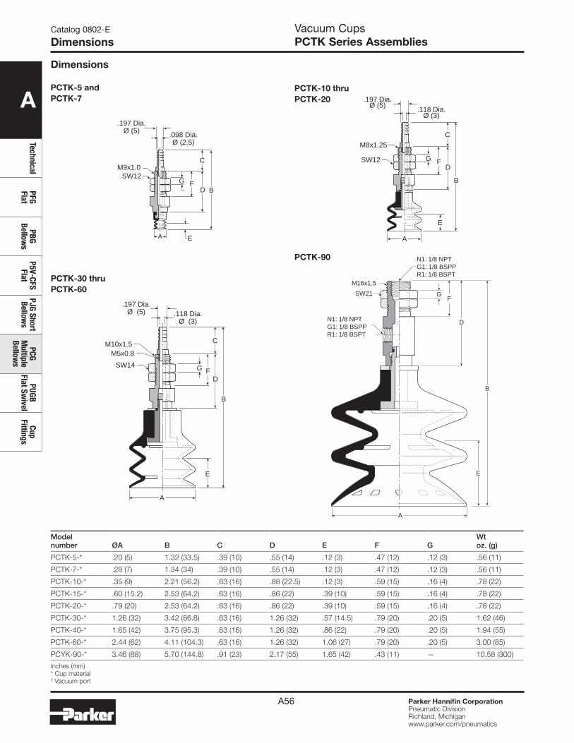
A
TechnicalPFG Flat
PBG Bellow
sP5V-CFS
FlatPJG Short Bellow
sPCG
Multiple
Bellows
PUGB Flat Sw
ivelCup
Fittings
Parker Hannifin CorporationPneumatic DivisionRichland, Michiganwww.parker.com/pneumatics
A56
PCTK-5 and PCTK-7
PCTK-10 thru PCTK-20
Modelnumber ØA B C D E F G
Wtoz. (g)
PCTK-5-* .20 (5) 1.32 (33.5) .39 (10) .55 (14) .12 (3) .47 (12) .12 (3) .56 (11)
PCTK-7-* .28 (7) 1.34 (34) .39 (10) .55 (14) .12 (3) .47 (12) .12 (3) .56 (11)
PCTK-10-* .35 (9) 2.21 (56.2) .63 (16) .88 (22.5) .12 (3) .59 (15) .16 (4) .78 (22)
PCTK-15-* .60 (15.2) 2.53 (64.2) .63 (16) .86 (22) .39 (10) .59 (15) .16 (4) .78 (22)
PCTK-20-* .79 (20) 2.53 (64.2) .63 (16) .86 (22) .39 (10) .59 (15) .16 (4) .78 (22)
PCTK-30-* 1.26 (32) 3.42 (86.8) .63 (16) 1.26 (32) .57 (14.5) .79 (20) .20 (5) 1.62 (46)
PCTK-40-* 1.65 (42) 3.75 (95.3) .63 (16) 1.26 (32) .86 (22) .79 (20) .20 (5) 1.94 (55)
PCTK-60-* 2.44 (62) 4.11 (104.3) .63 (16) 1.26 (32) 1.06 (27) .79 (20) .20 (5) 3.00 (85)
PCYK-90-* 3.46 (88) 5.70 (144.8) .91 (23) 2.17 (55) 1.65 (42) .43 (11) — 10.58 (300)
Inches (mm)* Cup material † Vacuum port
Catalog 0802-E
Dimensions
PCTK-30 thru PCTK-60
Dimensions
EA
.197 Dia.Ø (5)
.098 Dia.Ø (2.5)
FG
C
D B
M9x1.0SW12
B
FG
C
D
M8x1.25
SW12
.197 Dia.Ø (5)
.118 Dia.Ø (3)
E
A
B
FG
C
D
M10x1.5
SW14
.197 Dia.Ø (5) .118 Dia.
Ø (3)
A
E
M5x0.8
Vacuum CupsPCTK Series Assemblies
PCTK-90 N1: 1/8 NPTG1: 1/8 BSPPR1: 1/8 BSPT
N1: 1/8 NPTG1: 1/8 BSPPR1: 1/8 BSPT
SW21
M16x1.5
B
FG
D
A
E
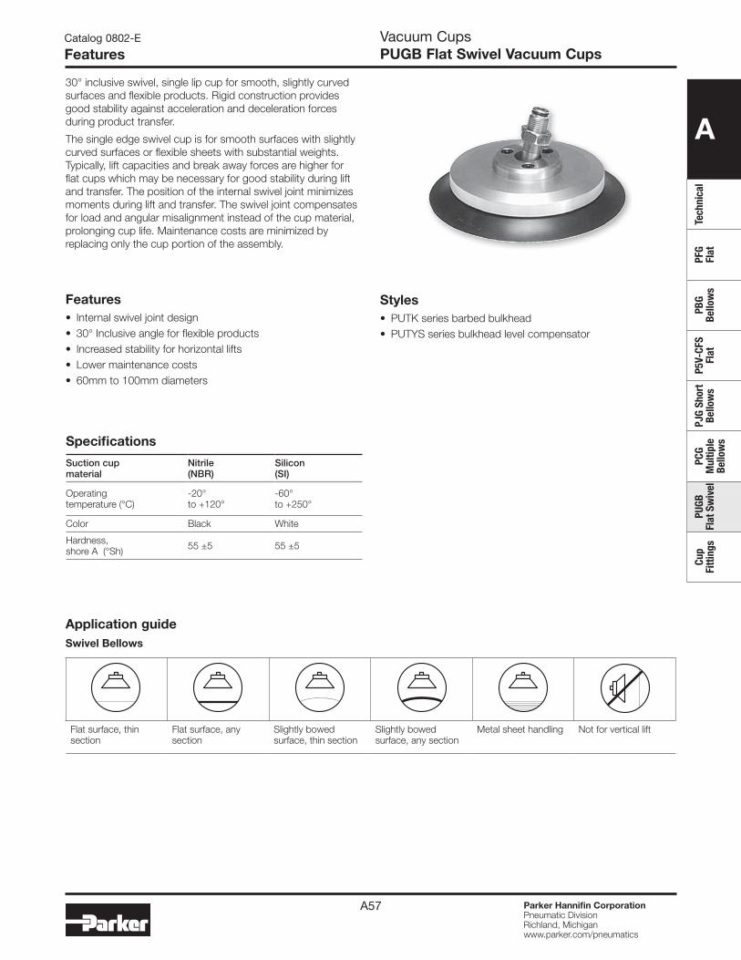
A
Tech
nica
lPF
G Fl
atPB
G Be
llow
sP5
V-CF
S Fl
atPJ
G Sh
ort
Bello
ws
PCG
Mul
tiple
Be
llow
s
PUGB
Fl
at S
wiv
elCu
p Fi
tting
s
Parker Hannifin CorporationPneumatic DivisionRichland, Michiganwww.parker.com/pneumatics
A57
Catalog 0802-E
FeaturesVacuum CupsPUGB Flat Swivel Vacuum Cups
Features• Internal swivel joint design• 30° Inclusive angle for flexible products• Increased stability for horizontal lifts• Lower maintenance costs• 60mm to 100mm diameters
Specifications
Suction cupmaterial
Nitrile (NBR)
Silicon (SI)
Operating temperature (°C)
-20° to +120°
-60° to +250°
Color Black White
Hardness, shore A (°Sh) 55 ±5 55 ±5
30° inclusive swivel, single lip cup for smooth, slightly curved surfaces and flexible products. Rigid construction provides good stability against acceleration and deceleration forces during product transfer.
The single edge swivel cup is for smooth surfaces with slightly curved surfaces or flexible sheets with substantial weights. Typically, lift capacities and break away forces are higher for flat cups which may be necessary for good stability during lift and transfer. The position of the internal swivel joint minimizes moments during lift and transfer. The swivel joint compensates for load and angular misalignment instead of the cup material, prolonging cup life. Maintenance costs are minimized by replacing only the cup portion of the assembly.
Styles• PUTK series barbed bulkhead• PUTYS series bulkhead level compensator
Application guideSwivel Bellows
Flat surface, thin section
Flat surface, any section
Slightly bowed surface, thin section
Slightly bowed surface, any section
Metal sheet handling Not for vertical lift

A
TechnicalPFG Flat
PBG Bellow
sP5V-CFS
FlatPJG Short Bellow
sPCG
Multiple
Bellows
PUGB Flat Sw
ivelCup
Fittings
Parker Hannifin CorporationPneumatic DivisionRichland, Michiganwww.parker.com/pneumatics
A58
Vacuum CupsPUGB Flat Swivel Vacuum Cups
Catalog 0802-E
Ordering Information
Installation MountingThread
Note:
When installing cup assemblies, use a sealant material to secure the assembly and prevent vacuum leakage.
PUTK Series Barbed BulkheadTop stem connectors secured with jam nuts and allow tubing connections at the top side. Fitting material: nickel plated brass.
PUTYS Series Bulkhead Level Compensator303 stainless steel construction secured with jam nuts. Spring biased compensators can absorb impacts of down-strokes and adjust for different levels of pick up points. 303 stainless corrosion resistant materials with drymet bushings increases the strength and life.
InstallationNote:When installing cup assemblies, use a sealant material to secure the assembly and prevent vacuum leakage.Shown are interchangable connectors & plugs for port connections.
MountingThread.
PlugPushlockTube Fitting
Barb Fitting
Inte
rcha
ngab
le*
* Not included with assembly
Cupsize
Vacumport
Cup material Nitrile assembly (NBR)
Replacement PUGB swivel with cup only
Replacement cup only (NBR)
Cup fitting
60 1/8 NPT PUTK-60-NBR-N1 PUGB-60-NBR PUG-60-NBR UTK-60-N1
80 1/8 NPT PUTK-80-NBR-N1 PUGB-80-NBR PUG-80-NBR UTK-60-N1
100 1/8 NPT PUTK-100-NBR-N1 PUGB-100-NBR PUG-100-NBR UTK-60-N1
Cup diameter (mm)
Vacum port
Stroke (mm)
Spring compression Force lbf (N)0% 100%
PUTYS assemlby (NBR)
Replacement PUGB swivel with cup only
Replacement cup only NBR
Level compensator P/N
60 1/8 NPT 30 1.6 (6.8) 3.6 (15.6) PUTYS6030NBRN1 PUGB-60-NBR PUG-60-NBR UTYS-60-30
60 1/8 NPT 50 1.9 (8.3) 4.5 (19.6) PUTYS6050NBRN1 PUGB-60-NBR PUG-60-NBR UTYS-60-50
80 1/8 NPT 30 1.6 (6.8) 3.6 (15.6) PUTYS8030NBRN1 PUGB-80-NBR PUG-80-NBR UTYS-60-30
80 1/8 NPT 50 1.9 (8.3) 4.5 (19.6) PUTYS8050NBRN1 PUGB-80-NBR PUG-80-NBR UTYS-60-50
100 1/8 NPT 30 1.6 (6.8) 3.6 (15.6) PUTYS10030NBRN1 PUGB-100-NBR PUG-100-NBR UTYS-60-30
100 1/8 NPT 50 1.9 (8.3) 4.5 (19.6) PUTYS10050NBRN1 PUGB-100-NBR PUG-100-NBR UTYS-60-50
Most popular.
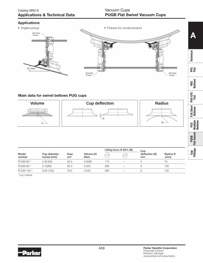
A
Tech
nica
lPF
G Fl
atPB
G Be
llow
sP5
V-CF
S Fl
atPJ
G Sh
ort
Bello
ws
PCG
Mul
tiple
Be
llow
s
PUGB
Fl
at S
wiv
elCu
p Fi
tting
s
Parker Hannifin CorporationPneumatic DivisionRichland, Michiganwww.parker.com/pneumatics
A59
Applications
Catalog 0802-E
Applications & Technical Data
Modelnumber
Cup diameterinches (mm)
Areacm2
Volume (V) liters
Lifting force @ 60% (N) Cupdeflection (S)mm
Radius R (mm)
PUGB-60-* 2.36 (60) 28.3 0.0090 173 — 5 70
PUGB-80-* 3.15(80) 50.3 0.025 308 — 6 100
PUGB-100-* 3.94 (100) 78.5 0.045 480 — 6 150
* Cup material
Main data for swivel bellows PUG cups
S
RV
Volume RadiusCup deflection
15° Max.
MountingThread
MountingThread
MountingThread
• Angles pickup • Fixtures for curved product
Vacuum CupsPUGB Flat Swivel Vacuum Cups
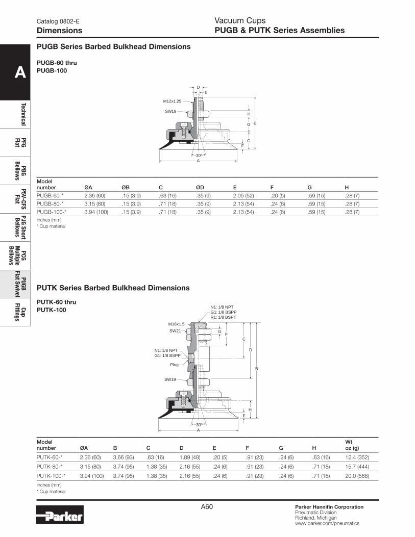
A
TechnicalPFG Flat
PBG Bellow
sP5V-CFS
FlatPJG Short Bellow
sPCG
Multiple
Bellows
PUGB Flat Sw
ivelCup
Fittings
Parker Hannifin CorporationPneumatic DivisionRichland, Michiganwww.parker.com/pneumatics
A60
Modelnumber ØA ØB C ØD E F G H
PUGB-60-* 2.36 (60) .15 (3.9) .63 (16) .35 (9) 2.05 (52) .20 (5) .59 (15) .28 (7)
PUGB-80-* 3.15 (80) .15 (3.9) .71 (18) .35 (9) 2.13 (54) .24 (6) .59 (15) .28 (7)
PUGB-100-* 3.94 (100) .15 (3.9) .71 (18) .35 (9) 2.13 (54) .24 (6) .59 (15) .28 (7)Inches (mm)* Cup material
Catalog 0802-E
Dimensions
PUGB-60 thruPUGB-100
BD
E
F
G
C
H
A30°
SW19
M12x1.25
Modelnumber ØA B C D E F G H
Wtoz (g)
PUTK-60-* 2.36 (60) 3.66 (93) .63 (16) 1.89 (48) .20 (5) .91 (23) .24 (6) .63 (16) 12.4 (352)
PUTK-80-* 3.15 (80) 3.74 (95) 1.38 (35) 2.16 (55) .24 (6) .91 (23) .24 (6) .71 (18) 15.7 (444)
PUTK-100-* 3.94 (100) 3.74 (95) 1.38 (35) 2.16 (55) .24 (6) .91 (23) .24 (6) .71 (18) 20.0 (568)
Inches (mm)* Cup material
PUTK-60 thruPUTK-100
PUTK Series Barbed Bulkhead Dimensions
PUGB Series Barbed Bulkhead Dimensions
B
EH
A30°
SW19
N1: 1/8 NPTG1: 1/8 BSPPR1: 1/8 BSPT
N1: 1/8 NPTG1: 1/8 BSPP
SW21
M16x1.5
FG
D
C
Plug
Vacuum CupsPUGB & PUTK Series Assemblies
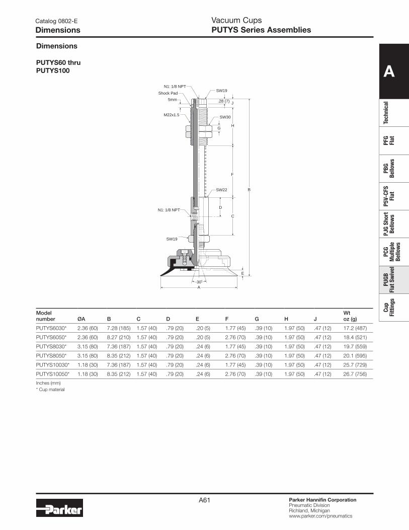
A
Tech
nica
lPF
G Fl
atPB
G Be
llow
sP5
V-CF
S Fl
atPJ
G Sh
ort
Bello
ws
PCG
Mul
tiple
Be
llow
s
PUGB
Fl
at S
wiv
elCu
p Fi
tting
s
Parker Hannifin CorporationPneumatic DivisionRichland, Michiganwww.parker.com/pneumatics
A61
Catalog 0802-E
Dimensions
Dimensions
Modelnumber ØA B C D E F G H J
Wtoz (g)
PUTYS6030* 2.36 (60) 7.28 (185) 1.57 (40) .79 (20) .20 (5) 1.77 (45) .39 (10) 1.97 (50) .47 (12) 17.2 (487)
PUTYS6050* 2.36 (60) 8.27 (210) 1.57 (40) .79 (20) .20 (5) 2.76 (70) .39 (10) 1.97 (50) .47 (12) 18.4 (521)
PUTYS8030* 3.15 (80) 7.36 (187) 1.57 (40) .79 (20) .24 (6) 1.77 (45) .39 (10) 1.97 (50) .47 (12) 19.7 (559)
PUTYS8050* 3.15 (80) 8.35 (212) 1.57 (40) .79 (20) .24 (6) 2.76 (70) .39 (10) 1.97 (50) .47 (12) 20.1 (595)
PUTYS10030* 1.18 (30) 7.36 (187) 1.57 (40) .79 (20) .24 (6) 1.77 (45) .39 (10) 1.97 (50) .47 (12) 25.7 (729)
PUTYS10050* 1.18 (30) 8.35 (212) 1.57 (40) .79 (20) .24 (6) 2.76 (70) .39 (10) 1.97 (50) .47 (12) 26.7 (756)
Inches (mm)* Cup material
PUTYS60 thruPUTYS100
E
A30˚
SW19
N1: 1/8 NPT
N1: 1/8 NPT
SW19
SW30M22x1.5
B
D
C
H
J.28 (7)
F
G
SW22
Shock Pad
5mm
Vacuum CupsPUTYS Series Assemblies
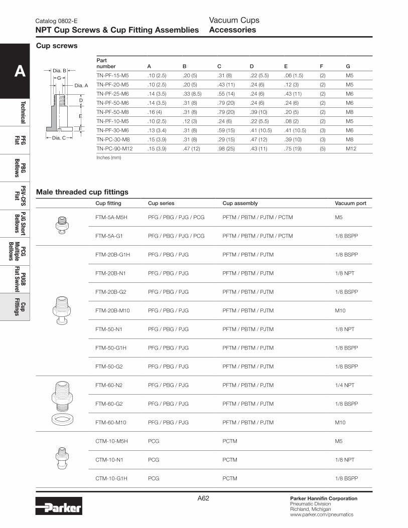
A
TechnicalPFG Flat
PBG Bellow
sP5V-CFS
FlatPJG Short Bellow
sPCG
Multiple
Bellows
PUGB Flat Sw
ivelCup
Fittings
Parker Hannifin CorporationPneumatic DivisionRichland, Michiganwww.parker.com/pneumatics
A62
Catalog 0802-E
NPT Cup Screws & Cup Fitting Assemblies
Partnumber A B C D E F G
TN-PF-15-M5 .10 (2.5) .20 (5) .31 (8) .22 (5.5) .06 (1.5) (2) M5
TN-PF-20-M5 .10 (2.5) .20 (5) .43 (11) .24 (6) .12 (3) (2) M5
TN-PF-25-M6 .14 (3.5) .33 (8.5) .55 (14) .24 (6) .43 (11) (2) M6
TN-PF-50-M6 .14 (3.5) .31 (8) .79 (20) .24 (6) .24 (6) (2) M6
TN-PF-50-M8 .16 (4) .31 (8) .79 (20) .39 (10) .20 (5) (2) M8
TN-PF-10-M5 .10 (2.5) .12 (3) .24 (6) .22 (5.5) .08 (2) (2) M5
TN-PF-30-M6 .13 (3.4) .31 (8) .59 (15) .41 (10.5) .41 (10.5) (3) M6
TN-PC-30-M8 .15 (3.9) .31 (8) .29 (15) .47 (12) .39 (10) (3) M8
TN-PC-90-M12 .15 (3.9) .47 (12) .98 (25) .43 (11) .75 (19) (5) M12
Inches (mm)
D
E
F
Dia. C
Dia. A
Dia. B
G
Cup screws
Vacuum CupsAccessories
Male threaded cup fittingsCup fitting Cup series Cup assembly Vacuum port
FTM-5A-M5H PFG / PBG / PJG / PCG PFTM / PBTM / PJTM / PCTM M5
FTM-5A-G1 PFG / PBG / PJG / PCG PFTM / PBTM / PJTM / PCTM 1/8 BSPP
FTM-20B-G1H PFG / PBG / PJG PFTM / PBTM / PJTM 1/8 BSPP
FTM-20B-N1 PFG / PBG / PJG PFTM / PBTM / PJTM 1/8 NPT
FTM-20B-G2 PFG / PBG / PJG PFTM / PBTM / PJTM 1/8 BSPP
FTM-20B-M10 PFG / PBG / PJG PFTM / PBTM / PJTM M10
FTM-50-N1 PFG / PBG / PJG PFTM / PBTM / PJTM 1/8 NPT
FTM-50-G1H PFG / PBG / PJG PFTM / PBTM / PJTM 1/8 BSPP
FTM-50-G2 PFG / PBG / PJG PFTM / PBTM / PJTM 1/8 BSPP
FTM-60-N2 PFG / PBG / PJG PFTM / PBTM / PJTM 1/4 NPT
FTM-60-G2 PFG / PBG / PJG PFTM / PBTM / PJTM 1/8 BSPP
FTM-60-M10 PFG / PBG / PJG PFTM / PBTM / PJTM M10
CTM-10-M5H PCG PCTM M5
CTM-10-N1 PCG PCTM 1/8 NPT
CTM-10-G1H PCG PCTM 1/8 BSPP
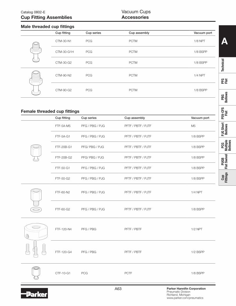
A
Tech
nica
lPF
G Fl
atPB
G Be
llow
sP5
V-CF
S Fl
atPJ
G Sh
ort
Bello
ws
PCG
Mul
tiple
Be
llow
s
PUGB
Fl
at S
wiv
elCu
p Fi
tting
s
Parker Hannifin CorporationPneumatic DivisionRichland, Michiganwww.parker.com/pneumatics
A63
Vacuum CupsAccessories
Catalog 0802-E
Cup Fitting Assemblies
Male threaded cup fittingsCup fitting Cup series Cup assembly Vacuum port
CTM-30-N1 PCG PCTM 1/8 NPT
CTM-30-G1H PCG PCTM 1/8 BSPP
CTM-30-G2 PCG PCTM 1/8 BSPP
CTM-90-N2 PCG PCTM 1/4 NPT
CTM-90-G2 PCG PCTM 1/8 BSPP
Female threaded cup fittingsCup fitting Cup series Cup assembly Vacuum port
FTF-5A-M5 PFG / PBG / PJG PFTF / PBTF / PJTF M5
FTF-5A-G1 PFG / PBG / PJG PFTF / PBTF / PJTF 1/8 BSPP
FTF-20B-G1 PFG/ PBG / PJG PFTF / PBTF / PJTF 1/8 BSPP
FTF-20B-G2 PFG/ PBG / PJG PFTF / PBTF / PJTF 1/8 BSPP
FTF-50-G1 PFG / PBG / PJG PFTF / PBTF / PJTF 1/8 BSPP
FTF-50-G2 PFG / PBG / PJG PFTF / PBTF / PJTF 1/8 BSPP
FTF-60-N2 PFG / PBG / PJG PFTF / PBTF / PJTF 1/4 NPT
FTF-60-G2 PFG / PBG / PJG PFTF / PBTF / PJTF 1/8 BSPP
FTF-120-N4 PFG / PBG PFTF / PBTF 1/2 NPT
FTF-120-G4 PFG / PBG PFTF / PBTF 1/2 BSPP
CTF-10-G1 PCG PCTF 1/8 BSPP
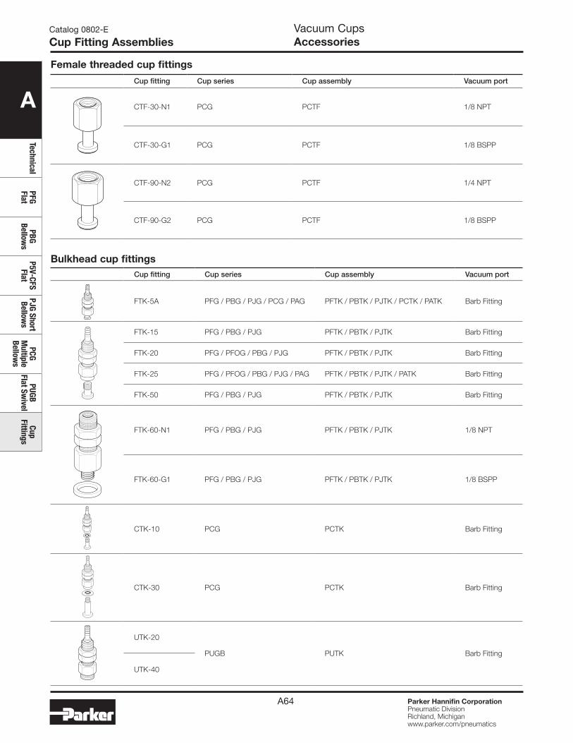
A
TechnicalPFG Flat
PBG Bellow
sP5V-CFS
FlatPJG Short Bellow
sPCG
Multiple
Bellows
PUGB Flat Sw
ivelCup
Fittings
Parker Hannifin CorporationPneumatic DivisionRichland, Michiganwww.parker.com/pneumatics
A64
Bulkhead cup fittingsCup fitting Cup series Cup assembly Vacuum port
FTK-5A PFG / PBG / PJG / PCG / PAG PFTK / PBTK / PJTK / PCTK / PATK Barb Fitting
FTK-15 PFG / PBG / PJG PFTK / PBTK / PJTK Barb Fitting
FTK-20 PFG / PFOG / PBG / PJG PFTK / PBTK / PJTK Barb Fitting
FTK-25 PFG / PFOG / PBG / PJG / PAG PFTK / PBTK / PJTK / PATK Barb Fitting
FTK-50 PFG / PBG / PJG PFTK / PBTK / PJTK Barb Fitting
FTK-60-N1 PFG / PBG / PJG PFTK / PBTK / PJTK 1/8 NPT
FTK-60-G1 PFG / PBG / PJG PFTK / PBTK / PJTK 1/8 BSPP
CTK-10 PCG PCTK Barb Fitting
CTK-30 PCG PCTK Barb Fitting
UTK-20
PUGB PUTK Barb Fitting
UTK-40
Female threaded cup fittings
Cup fitting Cup series Cup assembly Vacuum port
CTF-30-N1 PCG PCTF 1/8 NPT
CTF-30-G1 PCG PCTF 1/8 BSPP
CTF-90-N2 PCG PCTF 1/4 NPT
CTF-90-G2 PCG PCTF 1/8 BSPP
Vacuum CupsAccessories
Catalog 0802-E
Cup Fitting Assemblies
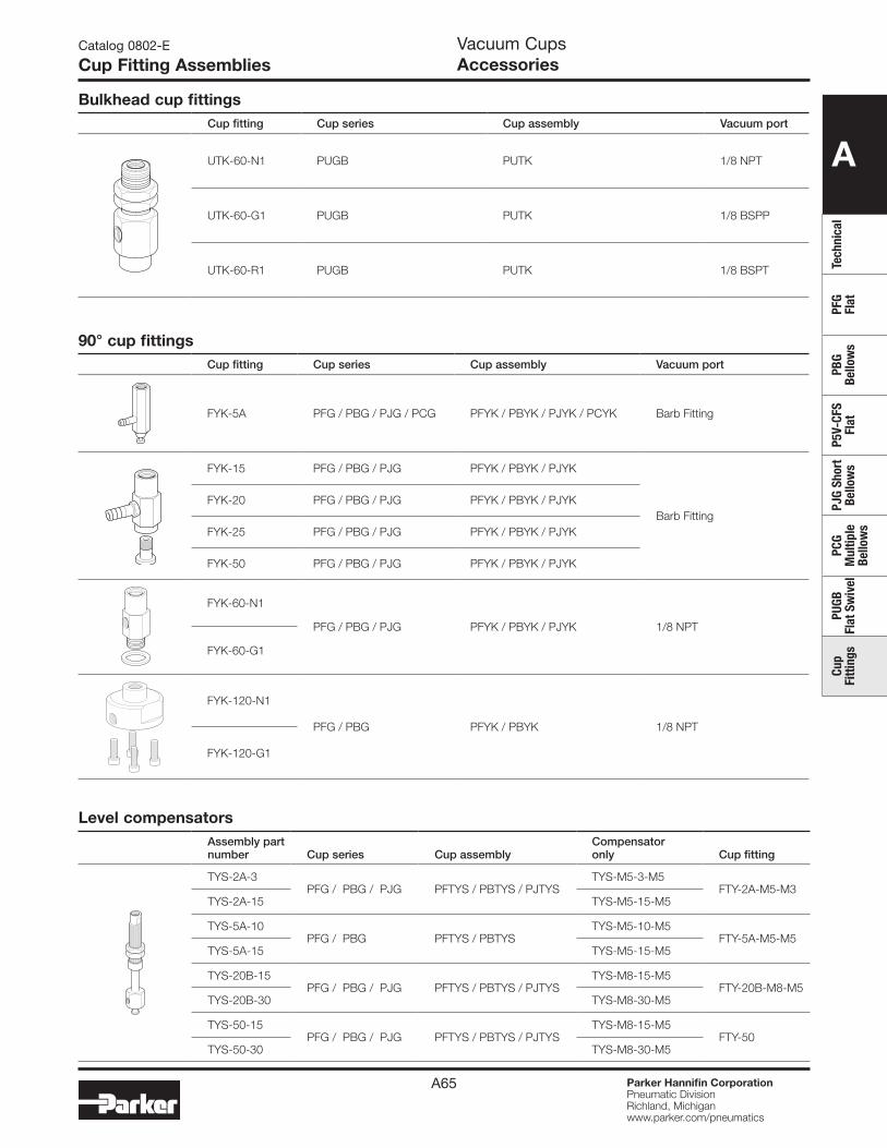
A
Tech
nica
lPF
G Fl
atPB
G Be
llow
sP5
V-CF
S Fl
atPJ
G Sh
ort
Bello
ws
PCG
Mul
tiple
Be
llow
s
PUGB
Fl
at S
wiv
elCu
p Fi
tting
s
Parker Hannifin CorporationPneumatic DivisionRichland, Michiganwww.parker.com/pneumatics
A65
Bulkhead cup fittingsCup fitting Cup series Cup assembly Vacuum port
UTK-60-N1 PUGB PUTK 1/8 NPT
UTK-60-G1 PUGB PUTK 1/8 BSPP
UTK-60-R1 PUGB PUTK 1/8 BSPT
90° cup fittingsCup fitting Cup series Cup assembly Vacuum port
FYK-5A PFG / PBG / PJG / PCG PFYK / PBYK / PJYK / PCYK Barb Fitting
FYK-15 PFG / PBG / PJG PFYK / PBYK / PJYK
Barb FittingFYK-20 PFG / PBG / PJG PFYK / PBYK / PJYK
FYK-25 PFG / PBG / PJG PFYK / PBYK / PJYK
FYK-50 PFG / PBG / PJG PFYK / PBYK / PJYK
FYK-60-N1
PFG / PBG / PJG PFYK / PBYK / PJYK 1/8 NPT
FYK-60-G1
FYK-120-N1
PFG / PBG PFYK / PBYK 1/8 NPT
FYK-120-G1
Level compensatorsAssembly part number Cup series Cup assembly
Compensator only Cup fitting
TYS-2A-3PFG / PBG / PJG PFTYS / PBTYS / PJTYS
TYS-M5-3-M5FTY-2A-M5-M3
TYS-2A-15 TYS-M5-15-M5
TYS-5A-10 PFG / PBG PFTYS / PBTYS
TYS-M5-10-M5FTY-5A-M5-M5
TYS-5A-15 TYS-M5-15-M5
TYS-20B-15 PFG / PBG / PJG PFTYS / PBTYS / PJTYS
TYS-M8-15-M5FTY-20B-M8-M5
TYS-20B-30 TYS-M8-30-M5
TYS-50-15PFG / PBG / PJG PFTYS / PBTYS / PJTYS
TYS-M8-15-M5FTY-50
TYS-50-30 TYS-M8-30-M5
Vacuum CupsAccessories
Catalog 0802-E
Cup Fitting Assemblies
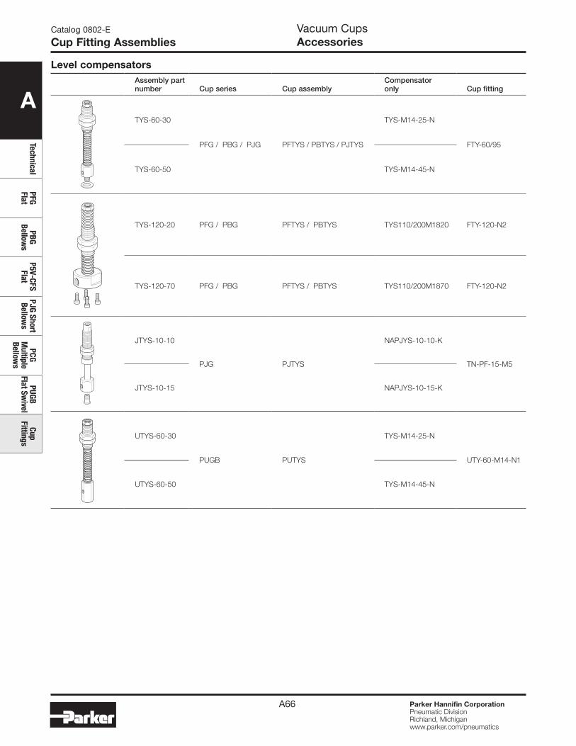
A
TechnicalPFG Flat
PBG Bellow
sP5V-CFS
FlatPJG Short Bellow
sPCG
Multiple
Bellows
PUGB Flat Sw
ivelCup
Fittings
Parker Hannifin CorporationPneumatic DivisionRichland, Michiganwww.parker.com/pneumatics
A66
Level compensatorsAssembly part number Cup series Cup assembly
Compensator only Cup fitting
TYS-60-30
PFG / PBG / PJG PFTYS / PBTYS / PJTYS
TYS-M14-25-N
FTY-60/95
TYS-60-50 TYS-M14-45-N
TYS-120-20 PFG / PBG PFTYS / PBTYS TYS110/200M1820 FTY-120-N2
TYS-120-70 PFG / PBG PFTYS / PBTYS TYS110/200M1870 FTY-120-N2
JTYS-10-10
PJG PJTYS
NAPJYS-10-10-K
TN-PF-15-M5
JTYS-10-15 NAPJYS-10-15-K
UTYS-60-30
PUGB PUTYS
TYS-M14-25-N
UTY-60-M14-N1
UTYS-60-50 TYS-M14-45-N
Vacuum CupsAccessories
Catalog 0802-E
Cup Fitting Assemblies

B1 Parker Hannifin CorporationPneumatic DivisionRichland, Michiganwww.parker.com/pneumatics
B
Gene
rato
r Se
lect
ion
MCA
, CV,
CV
-CK
CHF
MC2
2M
C72
CEK
CVXC
EKM
PS-2
3M
VS-2
01Ge
nera
tor
Acce
ssor
ies
Glos
sary
Vacuum Generators
Section Bwww.parker.com/pneu/vacgen
B2 Parker Hannifin CorporationPneumatic DivisionRichland, Michiganwww.parker.com/pneumatics
B
Generator Selection
MCA, CV,
CV-CKCHF
MC22
MC72
CEKCVXCEK
MPS-23
MVS-201
Generator Accessories
Glossary
Vacuum GeneratorsCatalog 0802-E
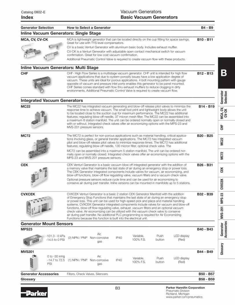
B3 Parker Hannifin CorporationPneumatic DivisionRichland, Michiganwww.parker.com/pneumatics
B
Gene
rato
r Se
lect
ion
MCA
, CV,
CV
-CK
CHF
MC2
2M
C72
CEK
CVXC
EKM
PS-2
3M
VS-2
01Ge
nera
tor
Acce
ssor
ies
Glos
sary
Generator Selection How to Select a Generator B4 - B9
Inline Vacuum Generators: Single StageMCA, CV, CV-CK MCA is lightweight generator that can be located directly on the cup fitting for space savings.
Great for use with TYS level compensators.CV is a basic Venturi Generator with aluminum basic body. Includes exhaust muffler.CV-CK is a Venturi Generator with adjustable open contact mechanical switch for vacuum confirmation. Great for low cost vacuum confirmation.Additional Pneumatic Control Valve is required to create vacuum flow with these products.
B10 - B11
Inline Vacuum Generators: Multi StageCHF CHF- High Flow Series is a multistage vacuum generator. CHF unit is intended for high flow
vacuum applications that due to system porosity issues have a low application degree of vacuum. These units are ideal for porous applications. 4 bolt mounting pattern with gauge opposite of vacuum and pressure inlet ports enables this generator to be panel mounted. CHF Series comes standard with flow thru exhaust mufflers to reduce clogging in dirty environments. Additional Pneumatic Control Valve is required to create vacuum flow.
B12 - B13
Integrated Vacuum GeneratorsMC22 The MC22 has integrated vacuum generating and blow-off release pilot valves to minimize the
response time to achieve vacuum. The small foot print and lightweight body allows the unit to be located close to the suction cup for maximum performance. The MC22 has additional features; regulating blow-off needle, 37 micron mesh filter, The MC22 can be assembled into a maximum 8 station manifold. The unit can be ordered normally open or normally closed and with or without. Integrated check valves offer air economizing options with the MPS-23 and MVS-201 pressure sensors.
B14 - B19
MC72 The MC72 is perfect for non-porous applications such as material handling, critical applica-tions involving glass, or general transfer applications. The MC72 has integrated vacuum pilot and blow-off release pilot valves to minimize response times. The MC72 has additional features; regulating blow-off needle, 130 micron filter, optional check valve. The
MC72 can be assembled into a maximum 5 station manifold. The unit can be ordered nor-mally open or normally closed. Integrated check valves offer air economizing options with the MPS-23 and MVS-201 pressure sensors.
B20 - B25
CEK CEK Venturi Generator is a basic vacuum blow off integrated generator with the addition of a memory valve that maintains the last state of air during an emergency stop or power loss. The CEK Generator integrated components include valves for vacuum, air economizing, and blow-off functions, blow-off flow regulating valve, vacuum filters and a vacuum check valve.Optional pressure sensors reduce cycle time and can be used for air economizing to conserve air during part transfer. Inline versions can be mounted in manifolds up to 5 stations.
B26 - B31
CVXCEK CVXCEK Venturi Generator is a basic 2 station CEK Generator Manifold with the addition of Emergency Stop Functions that maintains the last state of air during an emergency stop or power loss. This unit can be used for high-speed pick and place and material handling systems. CVXCEK Generator integrated components include valves for vacuum and blow-off functions, blow-off flow regulating valve, exhaust ,vacuum filters and an optional vacuum check valve. Air economizing can be utilized with the vacuum check valve to conserve air during part transfer. No additional PLC programming is required for Air Economizing Functions because this function is built into the electrical unit.
B32 - B39
Generator Mount SensorsMPS23
-101.3 - 0 kPa-14.5 to 0 PSI
(2) NPN / PNPAir,
Non-corrosive gas
IP40Variable,
100% F.S.Push
buttonLED display
(Red)
B40 - B43
MVS2010 to -30 inHg -14.7 to 72.5 PSI
(1) NPN / PNPAir,
Non-corrosive gas
IP40Variable,
100% F.S.Push
buttonLED display
(Red)
B44 - B49
Generator Accessories Filters, Check Valves, Silencers B50 - B57
Glossary B58 - B59
Vacuum GeneratorsBasic Vacuum Generators
Catalog 0802-E
Index
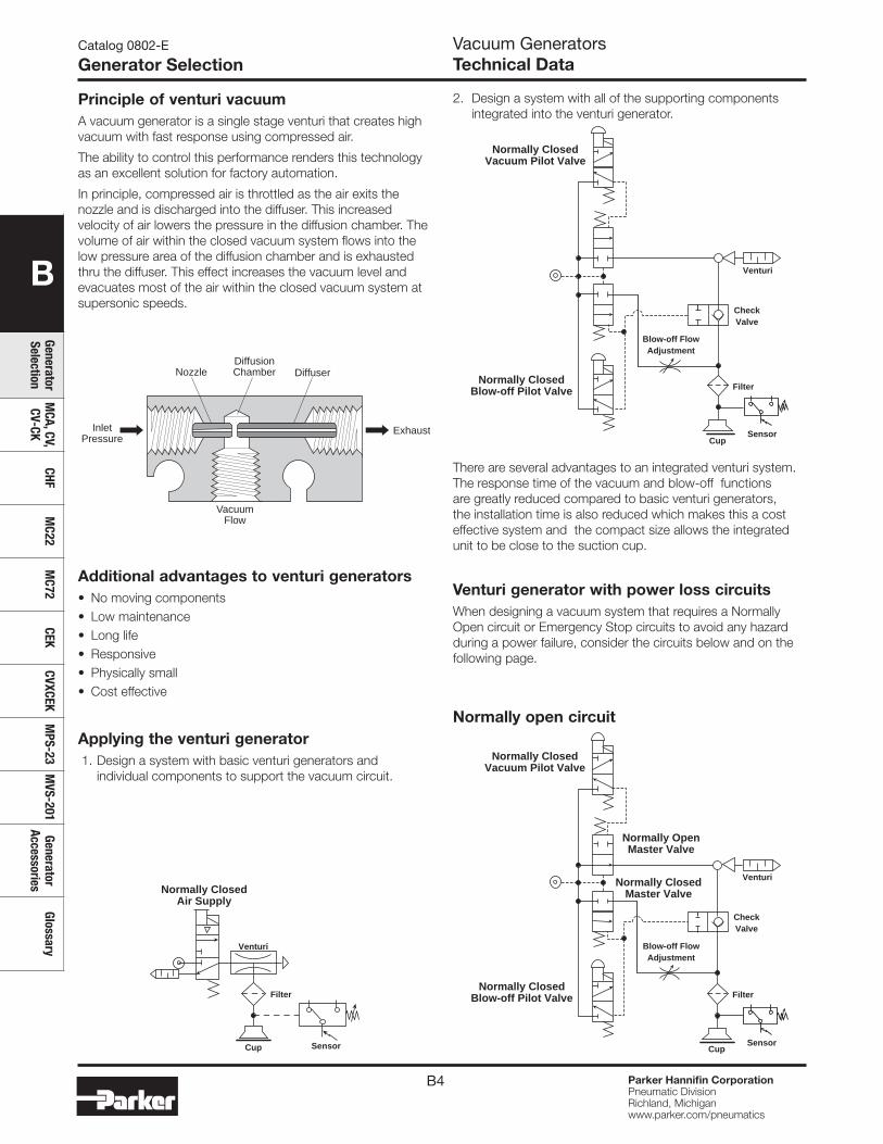
B4 Parker Hannifin CorporationPneumatic DivisionRichland, Michiganwww.parker.com/pneumatics
B
Generator Selection
MCA, CV,
CV-CKCHF
MC22
MC72
CEKCVXCEK
MPS-23
MVS-201
Generator Accessories
Glossary
Principle of venturi vacuumA vacuum generator is a single stage venturi that creates high vacuum with fast response using compressed air.
The ability to control this performance renders this technology as an excellent solution for factory automation.
In principle, compressed air is throttled as the air exits the nozzle and is discharged into the diffuser. This increased velocity of air lowers the pressure in the diffusion chamber. The volume of air within the closed vacuum system flows into the low pressure area of the diffusion chamber and is exhausted thru the diffuser. This effect increases the vacuum level and evacuates most of the air within the closed vacuum system at supersonic speeds.
Additional advantages to venturi generators• No moving components• Low maintenance• Long life• Responsive• Physically small• Cost effective
Applying the venturi generator 1. Design a system with basic venturi generators and
individual components to support the vacuum circuit.
Nozzle DiffuserDiffusion Chamber
Inlet Pressure
VacuumFlow
Exhaust
Venturi
Cup
Normally ClosedAir Supply
Filter
Sensor
Blow-off FlowAdjustment
Sensor
Filter
CheckValve
Venturi
Normally ClosedBlow-off Pilot Valve
Normally ClosedVacuum Pilot Valve
Cup
2. Design a system with all of the supporting components integrated into the venturi generator.
There are several advantages to an integrated venturi system. The response time of the vacuum and blow-off functions are greatly reduced compared to basic venturi generators, the installation time is also reduced which makes this a cost effective system and the compact size allows the integrated unit to be close to the suction cup.
Venturi generator with power loss circuitsWhen designing a vacuum system that requires a Normally Open circuit or Emergency Stop circuits to avoid any hazard during a power failure, consider the circuits below and on the following page.
Blow-off FlowAdjustment
Sensor
Filter
Venturi
Normally ClosedBlow-off Pilot Valve
Normally ClosedVacuum Pilot Valve
Normally OpenMaster Valve
Normally ClosedMaster Valve
CheckValve
Cup
Normally open circuit
Catalog 0802-E
Generator SelectionVacuum GeneratorsTechnical Data
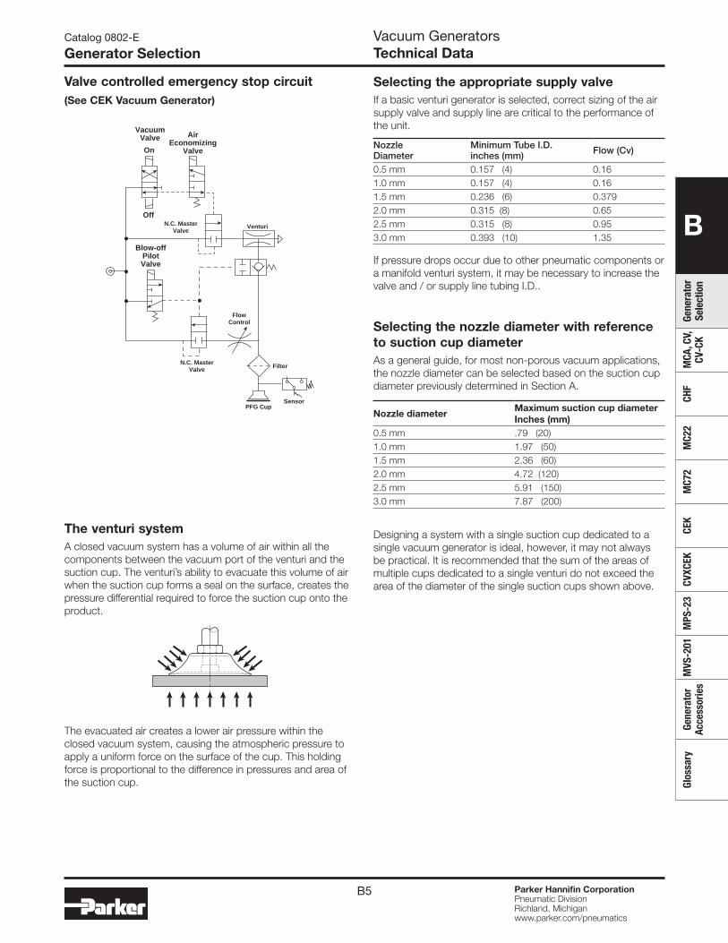
B5 Parker Hannifin CorporationPneumatic DivisionRichland, Michiganwww.parker.com/pneumatics
B
Gene
rato
r Se
lect
ion
MCA
, CV,
CV
-CK
CHF
MC2
2M
C72
CEK
CVXC
EKM
PS-2
3M
VS-2
01Ge
nera
tor
Acce
ssor
ies
Glos
sary
PFG Cup
On
Off
AirEconomizing
Valve
Sensor
VenturiN.C. MasterValve
N.C. MasterValve
Blow-offPilotValve
Filter
FlowControl
Vacuum Valve
Valve controlled emergency stop circuit(See CEK Vacuum Generator)
The venturi systemA closed vacuum system has a volume of air within all the components between the vacuum port of the venturi and the suction cup. The venturi’s ability to evacuate this volume of air when the suction cup forms a seal on the surface, creates the pressure differential required to force the suction cup onto the product.
The evacuated air creates a lower air pressure within the closed vacuum system, causing the atmospheric pressure to apply a uniform force on the surface of the cup. This holding force is proportional to the difference in pressures and area of the suction cup.
Nozzle Diameter
Minimum Tube I.D.inches (mm) Flow (Cv)
0.5 mm 0.157 (4) 0.161.0 mm 0.157 (4) 0.161.5 mm 0.236 (6) 0.3792.0 mm 0.315 (8) 0.652.5 mm 0.315 (8) 0.953.0 mm 0.393 (10) 1.35
Nozzle diameterMaximum suction cup diameterInches (mm)
0.5 mm .79 (20)1.0 mm 1.97 (50)1.5 mm 2.36 (60)2.0 mm 4.72 (120)2.5 mm 5.91 (150)3.0 mm 7.87 (200)
Catalog 0802-E
Generator SelectionVacuum GeneratorsTechnical Data
Selecting the appropriate supply valveIf a basic venturi generator is selected, correct sizing of the air supply valve and supply line are critical to the performance of the unit.
If pressure drops occur due to other pneumatic components or a manifold venturi system, it may be necessary to increase the valve and / or supply line tubing I.D..
Selecting the nozzle diameter with reference to suction cup diameterAs a general guide, for most non-porous vacuum applications, the nozzle diameter can be selected based on the suction cup diameter previously determined in Section A.
Designing a system with a single suction cup dedicated to a single vacuum generator is ideal, however, it may not always be practical. It is recommended that the sum of the areas of multiple cups dedicated to a single venturi do not exceed the area of the diameter of the single suction cups shown above.
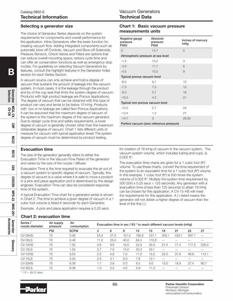
B6 Parker Hannifin CorporationPneumatic DivisionRichland, Michiganwww.parker.com/pneumatics
B
Generator Selection
MCA, CV,
CV-CKCHF
MC22
MC72
CEKCVXCEK
MPS-23
MVS-201
Generator Accessories
Glossary
Catalog 0802-E
Technical InformationVacuum GeneratorsTechnical Data
Selecting a generator size
Negative gaugepressurePSIG
AbsolutepressurePSIA
Inches of mercuryinHg
0 14.7 0
Atmospheric pressure at sea level
-1.5 13.2 3
-3.0 11.7 6
-4.5 10.2 9
Typical porous vacuum level
-6.0 8.7 12
-7.5 7.2 15
-9.0 5.7 18
-10.5 4.2 21
Typical non-porous vacuum level
-12.0 2.7 24
-13.5 1.2 27
-14.7 0 29.92
Perfect vacuum (zero reference pressure)
Chart 2: evacuation time
Chart 1: Basic vacuum pressure measurements units
The choice of Generator Series depends on the system requirements for components and overall performance for the application. Inline Generators offer the basic function for creating vacuum flow. Adding integrated components such as automatic blow off Controls, Vacuum and Blow-off Solenoids, Pressure Sensors, Check Valves and Filters are options that can reduce overall mounting space, reduce cycle time and can offer air conservation functions as well as emergency stop modes. For guidelines on selecting Vacuum Generators by features, consult the highlight features in the Generator Index section for each Series Section.
A vacuum source can only achieve and hold a degree of vacuum that sustains the amount of leakage into the vacuum system. In most cases, it is the leakage through the product and by of the cup seal that limits the system degree of vacuum. Products with high product leakage are Porous Applications. The degree of vacuum that can be obtained with this type of product can vary and tends to be below 10 inHg. Products with low or no leakage are called Non-Porous Applications. It can be assumed that the maximum degree of vacuum of the system is the maximum degree of the vacuum generator. Due to design cycle time and safety requirements, a lower degree of vacuum is generally chosen other than the maximum obtainable degree of vacuum. Chart 1 lists different units of measure for vacuum with typical application levels The system degree of vacuum must be determined by product testing.
Evacuation timeThe size of the generator generally refers to either the Evacuation Time or the Vacuum Flow Rates of the generator and varies by the size of the nozzle / diffuser.
Evacuation Time is the time required to evacuate the air out of a vacuum system to specific degree of vacuum. Typically, this degree of vacuum is a value where it is safe to move a product in a pick and place application and is determined by the design engineer. Evacuation Time can also be considered response time of the system.
A typical Evacuation Time chart for a generator series is shown in Chart 2. The time to achieve a given degree of vacuum in a 1 cubic foot volume is listed in seconds for each Generator.
Example: A pick and place application requires a 0.25 secs
for creation of 18 inHg of vacuum in the vacuum system. The vacuum system volume, which includes tubing and cups, is 0.002 ft3.
The evacuation time charts are given for a 1 cubic foot (ft3) volume. To use these charts, convert the time requirement of the system to an equivalent time for a 1 cubic foot (ft3) volume. In this example, 1 cubic foot (ft3) is 500 times the system volume of 0.002 ft3. Multiply the system time requirement by 500 (500 x 0.25 secs = 125 seconds). Any generator with a evacuation time of less than 125 seconds to attain 18 inHg can be chosen for this application. A CV-15-HS will meet the requirements for this application. A (-) listed means the generator will not obtain a higher degree of vacuum than the level of the first (-).
Series / nozzle diameter
Air supply pressure
Air consumption Evacuation time in sec / ft3 * to reach different vacuum levels (inHg)
PSI SCFM 3 6 9 12 15 18 21 24 27
CV-05HS 70 0.46 24.3 57.3 101.0 160.5 231.1 305.1 433.1 597.7 —
CV-05LS 70 0.46 11.0 23.4 40.0 64.4 110.2 — — — —
CV-10HS 70 1.55 4.8 9.9 16.0 24.9 35.9 51.4 77.4 117.5 226.0
CV-10LS 70 1.55 3.7 7.6 13.0 20.3 33.1 — — — —
CV-15HS 70 3.53 2.5 4.8 7.0 11.0 15.5 22.0 31.9 46.6 112.1
CV-15LS 70 3.53 2.0 3.1 5.0 7.6 12.1 — — — —
CV-20HS 70 6.36 1.7 2.8 5.0 6.5 9.0 13.0 18.9 27.4 60.7
CV-20LS 70 6.36 1.3 2.5 4.0 5.9 11.3 — — — —* 1 ft3 = 28.31 liters
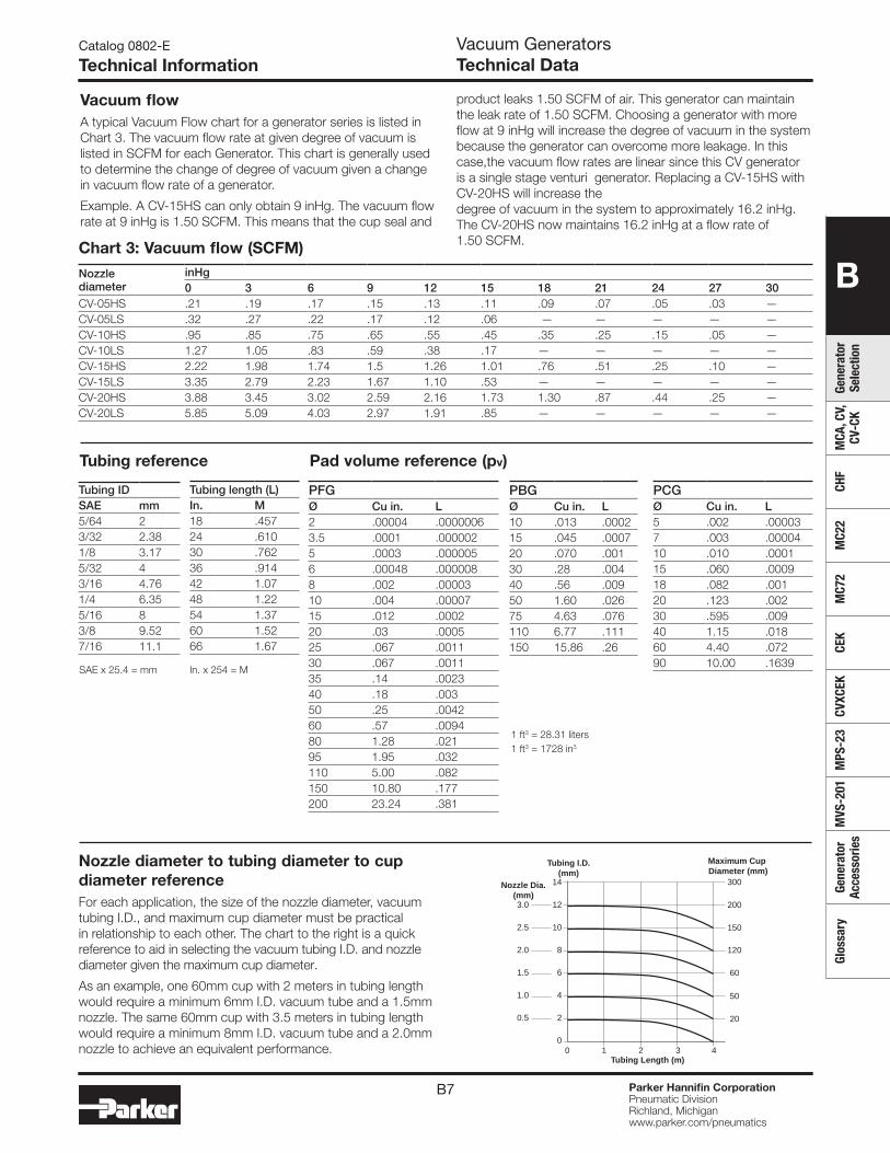
B7 Parker Hannifin CorporationPneumatic DivisionRichland, Michiganwww.parker.com/pneumatics
B
Gene
rato
r Se
lect
ion
MCA
, CV,
CV
-CK
CHF
MC2
2M
C72
CEK
CVXC
EKM
PS-2
3M
VS-2
01Ge
nera
tor
Acce
ssor
ies
Glos
sary
Catalog 0802-E
Technical InformationVacuum GeneratorsTechnical Data
Tubing length (L)In. M18 .45724 .61030 .76236 .91442 1.0748 1.2254 1.3760 1.5266 1.67
PFGØ Cu in. L2 .00004 .00000063.5 .0001 .0000025 .0003 .0000056 .00048 .0000088 .002 .0000310 .004 .0000715 .012 .000220 .03 .000525 .067 .001130 .067 .001135 .14 .002340 .18 .00350 .25 .004260 .57 .009480 1.28 .02195 1.95 .032110 5.00 .082150 10.80 .177200 23.24 .381
PBGØ Cu in. L10 .013 .000215 .045 .000720 .070 .00130 .28 .00440 .56 .00950 1.60 .02675 4.63 .076110 6.77 .111150 15.86 .26
Tubing reference Pad volume reference (pv)
PCGØ Cu in. L5 .002 .000037 .003 .0000410 .010 .000115 .060 .000918 .082 .00120 .123 .00230 .595 .00940 1.15 .01860 4.40 .07290 10.00 .1639
SAE x 25.4 = mm In. x 254 = M
1 ft3 = 28.31 liters1 ft3 = 1728 in3
2
00 1 2 3 4
4
6
8
10
12
14
0.5
1.0
1.5
2.0
2.5
3.0
Tubing I.D. (mm)
Nozzle Dia. (mm)
Maximum Cup Diameter (mm)
Tubing Length (m)
200
300
150
120
60
50
20
Nozzle diameter to tubing diameter to cup diameter referenceFor each application, the size of the nozzle diameter, vacuum tubing I.D., and maximum cup diameter must be practical in relationship to each other. The chart to the right is a quick reference to aid in selecting the vacuum tubing I.D. and nozzle diameter given the maximum cup diameter.
As an example, one 60mm cup with 2 meters in tubing length would require a minimum 6mm I.D. vacuum tube and a 1.5mm nozzle. The same 60mm cup with 3.5 meters in tubing length would require a minimum 8mm I.D. vacuum tube and a 2.0mm nozzle to achieve an equivalent performance.
Nozzlediameter
inHg0 3 6 9 12 15 18 21 24 27 30
CV-05HS .21 .19 .17 .15 .13 .11 .09 .07 .05 .03 —CV-05LS .32 .27 .22 .17 .12 .06 — — — — —CV-10HS .95 .85 .75 .65 .55 .45 .35 .25 .15 .05 —CV-10LS 1.27 1.05 .83 .59 .38 .17 — — — — —CV-15HS 2.22 1.98 1.74 1.5 1.26 1.01 .76 .51 .25 .10 —CV-15LS 3.35 2.79 2.23 1.67 1.10 .53 — — — — —CV-20HS 3.88 3.45 3.02 2.59 2.16 1.73 1.30 .87 .44 .25 —CV-20LS 5.85 5.09 4.03 2.97 1.91 .85 — — — — —
Chart 3: Vacuum flow (SCFM)
Vacuum flowA typical Vacuum Flow chart for a generator series is listed in Chart 3. The vacuum flow rate at given degree of vacuum is listed in SCFM for each Generator. This chart is generally used to determine the change of degree of vacuum given a change in vacuum flow rate of a generator.
Example. A CV-15HS can only obtain 9 inHg. The vacuum flow rate at 9 inHg is 1.50 SCFM. This means that the cup seal and
product leaks 1.50 SCFM of air. This generator can maintain the leak rate of 1.50 SCFM. Choosing a generator with more flow at 9 inHg will increase the degree of vacuum in the system because the generator can overcome more leakage. In this case,the vacuum flow rates are linear since this CV generator is a single stage venturi generator. Replacing a CV-15HS with CV-20HS will increase the degree of vacuum in the system to approximately 16.2 inHg. The CV-20HS now maintains 16.2 inHg at a flow rate of 1.50 SCFM.
Tubing IDSAE mm5/64 23/32 2.381/8 3.175/32 43/16 4.761/4 6.355/16 83/8 9.527/16 11.1
B8 Parker Hannifin CorporationPneumatic DivisionRichland, Michiganwww.parker.com/pneumatics
B
Generator Selection
MCA, CV,
CV-CKCHF
MC22
MC72
CEKCVXCEK
MPS-23
MVS-201
Generator Accessories
Glossary
Series / Nozzle diameter
Air supplypressurePSI
AirconsumptionSCFM
Evacuation time in sec / ft3 * to reach different vacuum levels (inHg)
3 6 9 12 15 18 21 24 27
MCA10HS 70 1.68 5.1 11.0 18.0 28.2 41.0 58.2 83.1 123.2 —
MCA13HS 70 2.81 3.7 7.3 12.0 19.5 28.5 39.8 58.5 104.2 —
CV05HS 70 0.46 24.3 57.3 101.0 160.5 231.1 305.1 433.1 597.7 —
CV05LS 70 0.46 11.0 23.4 40.0 64.4 110.2 — — — —
CV10HS 70 1.55 4.8 9.9 16.0 24.9 35.9 51.4 77.4 117.5 226.0
CV10LS 70 1.55 3.7 7.6 13.0 20.3 33.1 — — — —
CV15HS 70 3.53 2.5 4.8 7.0 11.0 15.5 22.0 31.9 46.6 112.1
CV15LS 70 3.53 2.0 3.1 5.0 7.6 12.1 — — — —
CV20HS 70 6.36 1.7 2.8 5.0 6.5 9.0 13.0 18.9 27.4 60.7
CV20LS 70 6.36 1.3 2.5 4.0 5.9 11.3 — — — —
CV25HS 70 9.36 1.4 2.3 3.0 4.5 6.5 9.0 13.0 18.9 35.3
CV25LS 70 9.36 1.0 2.0 3.0 3.7 5.6 — — — —
CV30AHS 70 13.60 1.1 2.0 2.8 3.5 4.8 6.8 9.6 16.7 29.1
CV30ALS 70 13.60 0.9 1.5 2.7 3.4 5.1 — — — —
CV10HSCK 70 1.55 4.8 9.9 16.0 24.9 35.9 51.4 77.4 117.5 226.0
CV15HSCK 70 3.53 2.5 4.8 7.0 11.0 15.5 22.0 31.9 46.6 112.1
CV20HSCK 70 6.36 0.7 2.8 5.0 6.5 9.0 13.0 18.9 27.4 60.7
CHF20 80 6.5 0.21 0.64 1.70 4.03 7.63 11.65 19.28 33.48 94.50
CHF30 80 9.6 0.21 0.63 1.27 3.39 6.36 9.53 16.10 27.76 78.82
CHF40 80 14.0 0.17 0.42 1.27 2.33 4.03 5.93 9.75 16.95 47.67
* 1 ft3 = 28.31 liters
Evacuation time
Catalog 0802-E
Evacuation Time, Vacuum FlowVacuum GeneratorsBasic Vacuum Generators
Vacuum flow (SCFM)
Nozzle diameter
nHg
0 3 6 9 12 15 18 21 24 27 30
MCA10HS .88 .78 .68 .58 .47 .37 .26 .16 .06 — —
MCA13HS 1.26 1.11 .96 .81 .67 .53 .39 .25 .11 — —
CV05HS .21 .19 .17 .15 .13 .11 .09 .07 .05 .03 —
CV05LS .32 .27 .22 .17 .12 .06 — — — — —
CV10HS .95 .85 .75 .65 .55 .45 .35 .25 .15 .05 —
CV10LS 1.27 1.05 .83 .59 .38 .17 — — — — —
CV15HS 2.22 1.98 1.74 1.50 1.26 1.01 .76 .51 .26 .10 —
CV15LS 3.35 2.79 2.23 1.67 1.10 .53 — — — — —
CV20HS 3.88 3.45 3.02 2.59 2.16 1.73 1.30 .87 .44 .25 —
CV20LS 5.85 5.09 4.03 2.97 1.91 .85 — — — — —
CV25HS 5.65 5.11 4.57 4.03 3.49 2.94 2.39 1.85 1.31 .77 —
CV25LS 8.83 7.29 5.75 4.21 2.67 1.13 — — — — —
CV30AHS 7.94 7.16 6.38 5.62 4.84 4.06 3.28 2.50 1.17 .92 —
CV30ALS 12.36 10.24 8.12 6.00 3.89 1.48 — — — — —
CV10HSCK .95 .85 .75 .65 .55 .45 .35 .25 .15 .05 —
CV15HSCK 2.22 1.98 1.74 1.5 1.26 1.01 .76 .51 .25 .10 —
CV20HSCK 3.88 3.45 3.02 2.59 2.16 1.73 1.30 .87 .44 .25 —
CHF20 20.90 12.12 7.88 3.85 2.76 2.12 1.45 0.81 0.35 0.04 —
CHF30 26.30 15.27 9.89 4.84 3.46 2.68 1.83 1.02 0.42 0.05 —
CHF40 31.80 18.50 12.00 5.90 4.20 3.30 2.30 1.30 0.60 0.06 —
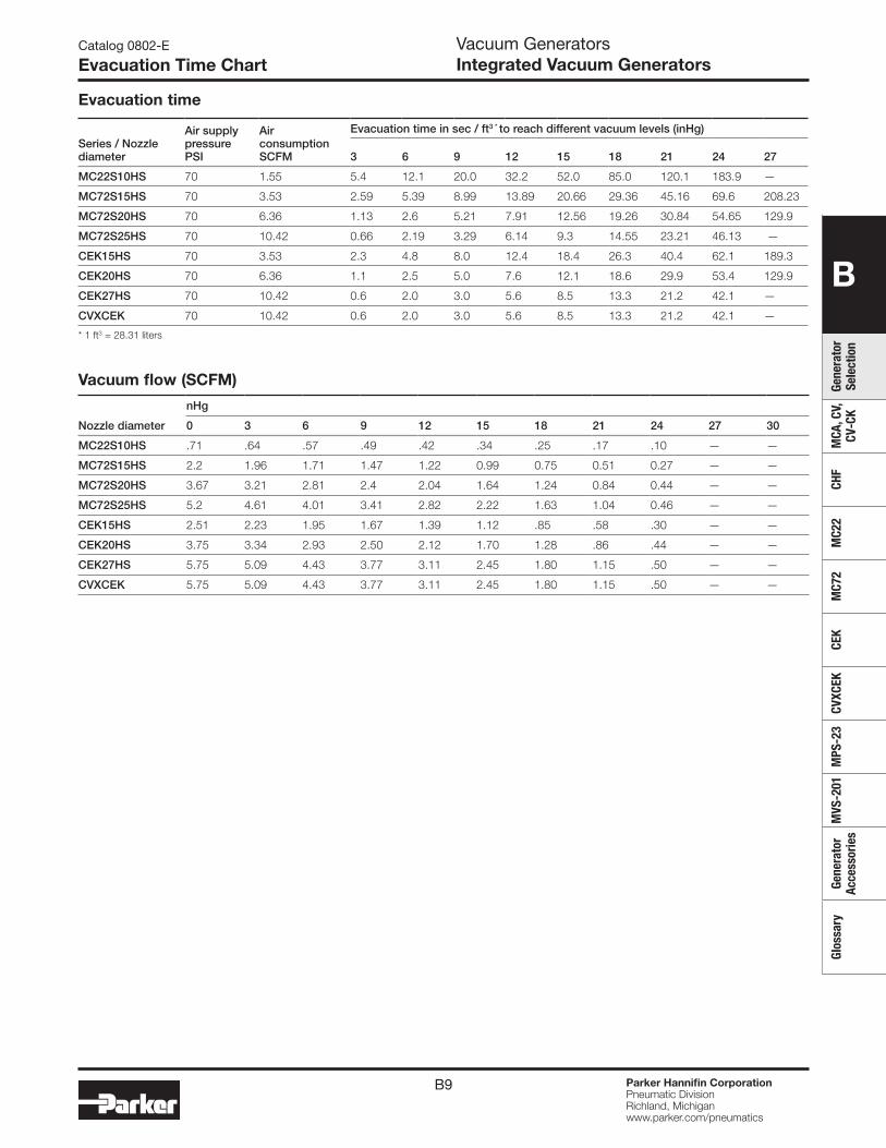
B9 Parker Hannifin CorporationPneumatic DivisionRichland, Michiganwww.parker.com/pneumatics
B
Gene
rato
r Se
lect
ion
MCA
, CV,
CV
-CK
CHF
MC2
2M
C72
CEK
CVXC
EKM
PS-2
3M
VS-2
01Ge
nera
tor
Acce
ssor
ies
Glos
sary
Vacuum GeneratorsIntegrated Vacuum Generators
Catalog 0802-E
Evacuation Time Chart
Series / Nozzle diameter
Air supplypressurePSI
AirconsumptionSCFM
Evacuation time in sec / ft3 * to reach different vacuum levels (inHg)
3 6 9 12 15 18 21 24 27
MC22S10HS 70 1.55 5.4 12.1 20.0 32.2 52.0 85.0 120.1 183.9 —
MC72S15HS 70 3.53 2.59 5.39 8.99 13.89 20.66 29.36 45.16 69.6 208.23
MC72S20HS 70 6.36 1.13 2.6 5.21 7.91 12.56 19.26 30.84 54.65 129.9
MC72S25HS 70 10.42 0.66 2.19 3.29 6.14 9.3 14.55 23.21 46.13 —
CEK15HS 70 3.53 2.3 4.8 8.0 12.4 18.4 26.3 40.4 62.1 189.3
CEK20HS 70 6.36 1.1 2.5 5.0 7.6 12.1 18.6 29.9 53.4 129.9
CEK27HS 70 10.42 0.6 2.0 3.0 5.6 8.5 13.3 21.2 42.1 —
CVXCEK 70 10.42 0.6 2.0 3.0 5.6 8.5 13.3 21.2 42.1 —
* 1 ft3 = 28.31 liters
Evacuation time
Vacuum flow (SCFM)
Nozzle diameter
nHg
0 3 6 9 12 15 18 21 24 27 30
MC22S10HS .71 .64 .57 .49 .42 .34 .25 .17 .10 — —
MC72S15HS 2.2 1.96 1.71 1.47 1.22 0.99 0.75 0.51 0.27 — —
MC72S20HS 3.67 3.21 2.81 2.4 2.04 1.64 1.24 0.84 0.44 — —
MC72S25HS 5.2 4.61 4.01 3.41 2.82 2.22 1.63 1.04 0.46 — —
CEK15HS 2.51 2.23 1.95 1.67 1.39 1.12 .85 .58 .30 — —
CEK20HS 3.75 3.34 2.93 2.50 2.12 1.70 1.28 .86 .44 — —
CEK27HS 5.75 5.09 4.43 3.77 3.11 2.45 1.80 1.15 .50 — —
CVXCEK 5.75 5.09 4.43 3.77 3.11 2.45 1.80 1.15 .50 — —

B10 Parker Hannifin CorporationPneumatic DivisionRichland, Michiganwww.parker.com/pneumatics
B
Generator Selection
MCA, CV,
CV-CKCHF
MC22
MC72
CEKCVXCEK
MPS-23
MVS-201
Generator Accessories
Glossary
Catalog 0802-E
Features & CharacteristicsVacuum GeneratorsMCA, CV, CV-CK
Parker Inline Single Stage Vacuum Generators is a compact design offering multiple vacuum flow ranges in 3 styles. These Generators are meant to be mounted near the vacuum application for improved vacuum response time. A Normally Open or Normally Closed 3 way valve can be used to control the supply pressure to obtain up to a 27 Inhg degree of vacuum.
Features• MCA:
- light weight vacuum generator - vacuum flow rates to 1.26 SCFM
• CV: - basic aluminum body generator with exhaust muffler - vacuum flow rates to 12.36 SCFM - degree of vacuum to 27 inHg
• CV-CK - basic aluminum body generator with mechanical vacuum switch - vacuum flow rates to 5.85 SCFM - degree of vacuum to 27 inHg
Model numbers
Symbol
Port size Max. vacuum flowSCFM
Air consumptionSCFM
Max. degree of vacuuminHg
Part number Part number
Pressure Vacuum Exhaust NPT BSPP
MCA Series1/8 1/8 1/4 1.68 1.68 24 MCA10HSN1N1N2 MCA10HSG1G1N2
1/4 1/4 1/4 2.81 2.81 24 MCA13HSN1N1N2 MCA13HSG1G1G2
CV Series 1/8 1/8 Muffler 0.21 0.46 27 CV05HSN CV05HSG
1/8 1/8 Muffler 0.32 0.46 17 CV05LSN CV05LSG
1/8 1/8 Muffler 0.95 1.55 27 CV10HSN CV10HSG
1/8 1/8 Muffler 1.27 1.55 17 CV10LSN CV10LSG
1/4 3/8 Muffler 2.22 3.53 27 CV15HSN CV15HSG
1/4 3/8 Muffler 3.35 3.53 17 CV15LSN CV15LSG
1/4 3/8 Muffler 3.88 6.36 27 CV20HSN CV20HSG
1/4 1/2 Muffler 5.85 6.36 17 CV20LSN CV20LSG
3/8 1/2 Muffler 5.65 9.36 27 CV25HSN CV25HSG
3/8 1/2 Muffler 8.83 9.36 17 CV25LSN CV25LSG
1/2 3/4 Muffler 7.94 13.60 27 CV30AHSN CV30AHSG
1/2 3/4 Muffler 12.36 13.60 17 CV30ALSN CV30ALSG
CV-CK Series 1/8 1/8 — 0.95 1.55 27 CV10HSCKN CV10HSCKG
1/4 1/4 — 2.22 3.53 27 CV15HSCKN CV15HSCKG
1/4 3/8 — 3.88 6.36 27 CV20HSCKN CV20HSCKG
Specifications
Media Non-lubricated air, non-corrosive gases
Operating pressure 14 to 114 PSI
Operating temperature 32° to 120°F (MCA, CV); 32 to 140°F (CV-CK)
MaterialPolycarbonate, Aluminum fittings (MCA)
Body: Aluminum (CV, CV-CK)Nozzle: Nickel plated brass (CV, CV-CK)
CV-CK Switch
Setting range: 5.9 to 15.7 inHg, accuracy ± 1.57 inHg
Hysteresis: 1.1 to 3.9 inHg
Switch output: N.O., AC125V; 5A, AC250V: 3A, DC250V: 0.2A
P
V
V
P
P
V
E
Most popular.
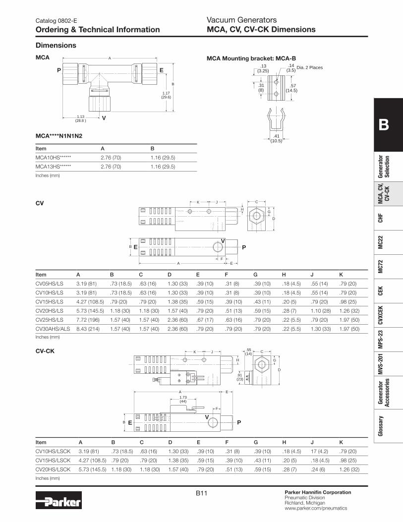
B11 Parker Hannifin CorporationPneumatic DivisionRichland, Michiganwww.parker.com/pneumatics
B
Gene
rato
r Se
lect
ion
MCA
, CV,
CV
-CK
CHF
MC2
2M
C72
CEK
CVXC
EKM
PS-2
3M
VS-2
01Ge
nera
tor
Acce
ssor
ies
Glos
sary
Catalog 0802-E
Ordering & Technical InformationVacuum GeneratorsMCA, CV, CV-CK Dimensions
Dimensions
D
G
CK
H
J
B
EA
PE
F
V
Item A B C D E F G H J K
CV05HS/LS 3.19 (81) .73 (18.5) .63 (16) 1.30 (33) .39 (10) .31 (8) .39 (10) .18 (4.5) .55 (14) .79 (20)
CV10HS/LS 3.19 (81) .73 (18.5) .63 (16) 1.30 (33) .39 (10) .31 (8) .39 (10) .18 (4.5) .55 (14) .79 (20)
CV15HS/LS 4.27 (108.5) .79 (20) .79 (20) 1.38 (35) .59 (15) .39 (10) .43 (11) .20 (5) .79 (20) .98 (25)
CV20HS/LS 5.73 (145.5) 1.18 (30) 1.18 (30) 1.57 (40) .79 (20) .51 (13) .59 (15) .28 (7) 1.10 (28) 1.26 (32)
CV25HS/LS 7.72 (196) 1.57 (40) 1.57 (40) 2.36 (60) .67 (17) .63 (16) .79 (20) .22 (5.5) .79 (20) 1.97 (50)
CV30AHS/ALS 8.43 (214) 1.57 (40) 1.57 (40) 2.36 (60) .79 (20) .79 (20) .79 (20) .22 (5.5) 1.30 (33) 1.97 (50)
Inches (mm)
Item A B
MCA10HS****** 2.76 (70) 1.16 (29.5)
MCA13HS****** 2.76 (70) 1.16 (29.5)
Inches (mm)
1.13(28.8 )
1.17(29.6)
B
A
P E
V
MCA****N1N1N2
MCA
CV
CV-CK
Item A B C D E F G H J K
CV10HS/LSCK 3.19 (81) .73 (18.5) .63 (16) 1.30 (33) .39 (10) .31 (8) .39 (10) .18 (4.5) 17 (4.2) .79 (20)
CV15HS/LSCK 4.27 (108.5) .79 (20) .79 (20) 1.38 (35) .59 (15) .39 (10) .43 (11) .20 (5) .18 (4.5) .98 (25)
CV20HS/LSCK 5.73 (145.5) 1.18 (30) 1.18 (30) 1.57 (40) .79 (20) .51 (13) .59 (15) .28 (7) .24 (6) 1.26 (32)
Inches (mm)
D
G
C.55(14)
1.73(44)
.91 (23)
EA
K
H
J
B PE
F
V
.41(10.5)
.14(3.5)
.31(8)
.13(3.25)
.57(14.5)
Dia. 2 Places
MCA Mounting bracket: MCA-B
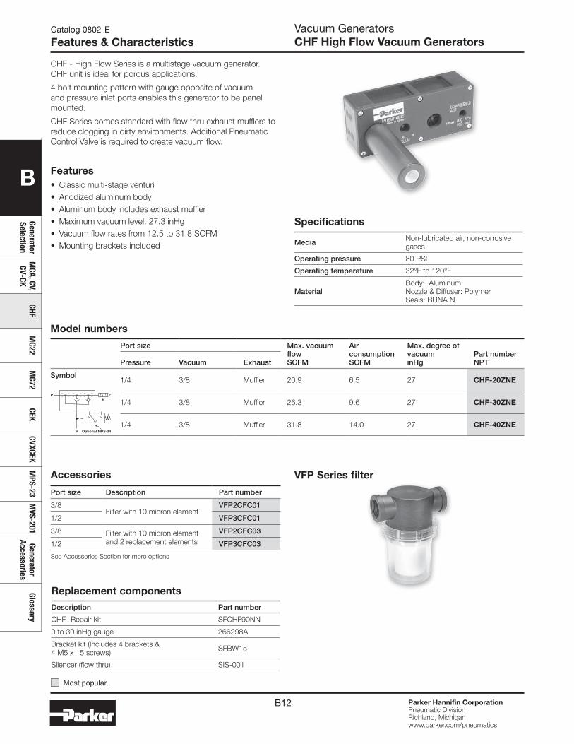
B12 Parker Hannifin CorporationPneumatic DivisionRichland, Michiganwww.parker.com/pneumatics
B
Generator Selection
MCA, CV,
CV-CKCHF
MC22
MC72
CEKCVXCEK
MPS-23
MVS-201
Generator Accessories
Glossary
Catalog 0802-E
Features & CharacteristicsVacuum GeneratorsCHF High Flow Vacuum Generators
Features• Classic multi-stage venturi• Anodized aluminum body• Aluminum body includes exhaust muffler• Maximum vacuum level, 27.3 inHg• Vacuum flow rates from 12.5 to 31.8 SCFM• Mounting brackets included
CHF - High Flow Series is a multistage vacuum generator. CHF unit is ideal for porous applications.
4 bolt mounting pattern with gauge opposite of vacuum and pressure inlet ports enables this generator to be panel mounted.
CHF Series comes standard with flow thru exhaust mufflers to reduce clogging in dirty environments. Additional Pneumatic Control Valve is required to create vacuum flow.
Specifications
Media Non-lubricated air, non-corrosive gases
Operating pressure 80 PSI
Operating temperature 32°F to 120°F
MaterialBody: AluminumNozzle & Diffuser: Polymer Seals: BUNA N
Replacement components
Description Part number
CHF- Repair kit SFCHF90NN
0 to 30 inHg gauge 266298A
Bracket kit (Includes 4 brackets & 4 M5 x 15 screws) SFBW15
Silencer (flow thru) SIS-001
Model numbers
Port size Max. vacuum flowSCFM
Air consumptionSCFM
Max. degree of vacuuminHg
Part number NPTPressure Vacuum Exhaust
Symbol1/4 3/8 Muffler 20.9 6.5 27 CHF-20ZNE
1/4 3/8 Muffler 26.3 9.6 27 CHF-30ZNE
1/4 3/8 Muffler 31.8 14.0 27 CHF-40ZNEV
PE
Optional MPS-34
VFP Series filter
Most popular.
Accessories
Port size Description Part number
3/8Filter with 10 micron element
VFP2CFC01
1/2 VFP3CFC01
3/8 Filter with 10 micron element and 2 replacement elements
VFP2CFC03
1/2 VFP3CFC03
See Accessories Section for more options
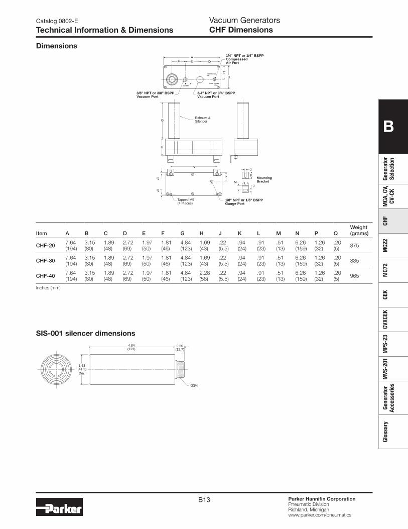
B13 Parker Hannifin CorporationPneumatic DivisionRichland, Michiganwww.parker.com/pneumatics
B
Gene
rato
r Se
lect
ion
MCA
, CV,
CV
-CK
CHF
MC2
2M
C72
CEK
CVXC
EKM
PS-2
3M
VS-2
01Ge
nera
tor
Acce
ssor
ies
Glos
sary
Item A B C D E F G H J K L M N P QWeight(grams)
CHF-20 7.64 (194)
3.15 (80)
1.89 (48)
2.72 (69)
1.97 (50)
1.81 (46)
4.84 (123)
1.69 (43)
.22 (5.5)
.94 (24)
.91 (23)
.51 (13)
6.26 (159)
1.26 (32)
.20 (5) 875
CHF-30 7.64 (194)
3.15 (80)
1.89 (48)
2.72 (69)
1.97 (50)
1.81 (46)
4.84 (123)
1.69 (43)
.22 (5.5)
.94 (24)
.91 (23)
.51 (13)
6.26 (159)
1.26 (32)
.20 (5) 885
CHF-40 7.64 (194)
3.15 (80)
1.89 (48)
2.72 (69)
1.97 (50)
1.81 (46)
4.84 (123)
2.28 (58)
.22 (5.5)
.94 (24)
.91 (23)
.51 (13)
6.26 (159)
1.26 (32)
.20(5) 965
Inches (mm)
Catalog 0802-E
Technical Information & DimensionsVacuum GeneratorsCHF Dimensions
DimensionsA
G
K
J
JN
PQ
Q
L
B
C
DEF
H
Pmax 700 kPa 102 psi
MMountingBracket
3/8" NPT or 3/8" BSPPVacuum Port
3/4" NPT or 3/4" BSPPVacuum Port
1/4" NPT or 1/4" BSPP CompressedAir Port
1/8" NPT or 1/8" BSPPGauge Port
Tapped M5(4 Places)
Exhaust &Silencer
VACUUM
COMPRESSEDAIR
SIS-001 silencer dimensions4.84(123)
0.50(12.7)
G3/4
1.63(41.3)Dia.
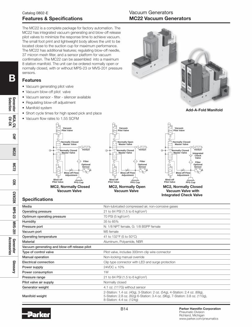
B14 Parker Hannifin CorporationPneumatic DivisionRichland, Michiganwww.parker.com/pneumatics
B
Generator Selection
MCA, CV,
CV-CKCHF
MC22
MC72
CEKCVXCEK
MPS-23
MVS-201
Generator Accessories
Glossary
Catalog 0802-E
Features & SpecificationsVacuum GeneratorsMC22 Vacuum Generators
SpecificationsMedia Non-lubricated compressed air, non-corrosive gases
Operating pressure 21 to 84 PSI (1.5 to 6 kgf/cm2)
Optimum operating pressure 70 PSI (5 kgf/cm2)
Humidity 35 to 85%
Pressure port N: 1/8 NPT female, G: 1/8 BSPP female
Vacuum port M5 female
Operating temperature 41 to 132°F (5 to 50°C)
Material Aluminum, Polyamide, NBR
Vacuum generating and blow-off release pilot
Type of control valve Pilot valve, includes 300mm clip wire connector
Manual operation Non-locking manual override
Electrical connection Clip type connector with LED and surge protection
Power supply 24VDC ± 10%
Power consumption 1W
Pressure range 21 to 84 PSI (1.5 to 6 kgf/cm2)
Pilot valve air supply Normally closed
Generator weight 4.1 oz. (117G) without sensor
Manifold weight2-Station: 1.4 oz. (40g), 3-Station: 2 oz. (54g), 4-Station: 2.4 oz. (68g), 5-Station: 2.8 oz. (82g) 6-Station: 3.4 oz. (96g), 7-Station: 3.8 oz. (110g), 8-Station: 4.4 oz. (124g)
Blow-off FlowAdjustment
OptionalSensor
Filter
Venturi
Blow-offPilot Valve
VacuumPilot Valve
Normally ClosedMaster Valve
Normally ClosedMaster Valve
Blow-off FlowAdjustment
OptionalSensor
Filter
Venturi
Blow-offPilot Valve
VacuumPilot Valve
Normally OpenMaster Valve
Normally ClosedMaster Valve
PFG Cup PFG Cup
Blow-off FlowAdjustment
OptionalSensor
Filter
IntegratedCheckValve
Venturi
Blow-offPilot Valve
VacuumPilot Valve
Normally ClosedMaster Valve
Normally ClosedMaster Valve
PFG Cup
Features• Vacuum generating pilot valve • Vacuum blow-off pilot valve • Vacuum sensor - filter - silencer available • Regulating blow-off adjustment • Manifold system • Short cycle times for high speed pick and place• Vacuum flow rates to 1.55 SCFM
The MC22 is a complete package for factory automation. The MC22 has integrated vacuum generating and blow-off release pilot valves to minimize the response time to achieve vacuum. The small foot print and lightweight body allows the unit to be located close to the suction cup for maximum performance. The MC22 has additional features; regulating blow-off needle, 37 micron mesh filter, and a sensor platform for vacuum confirmation. The MC22 can be assembled into a maximum 8 station manifold. The unit can be ordered normally open or normally closed, with or without MPS-23 or MVS-201 pressure sensors.
Add-A-Fold Manifold
MC2, Normally Closed Vacuum Valve
MC2, Normally Open Vacuum Valve
MC2, Normally Closed Vacuum Valve with
Integrated Check Valve
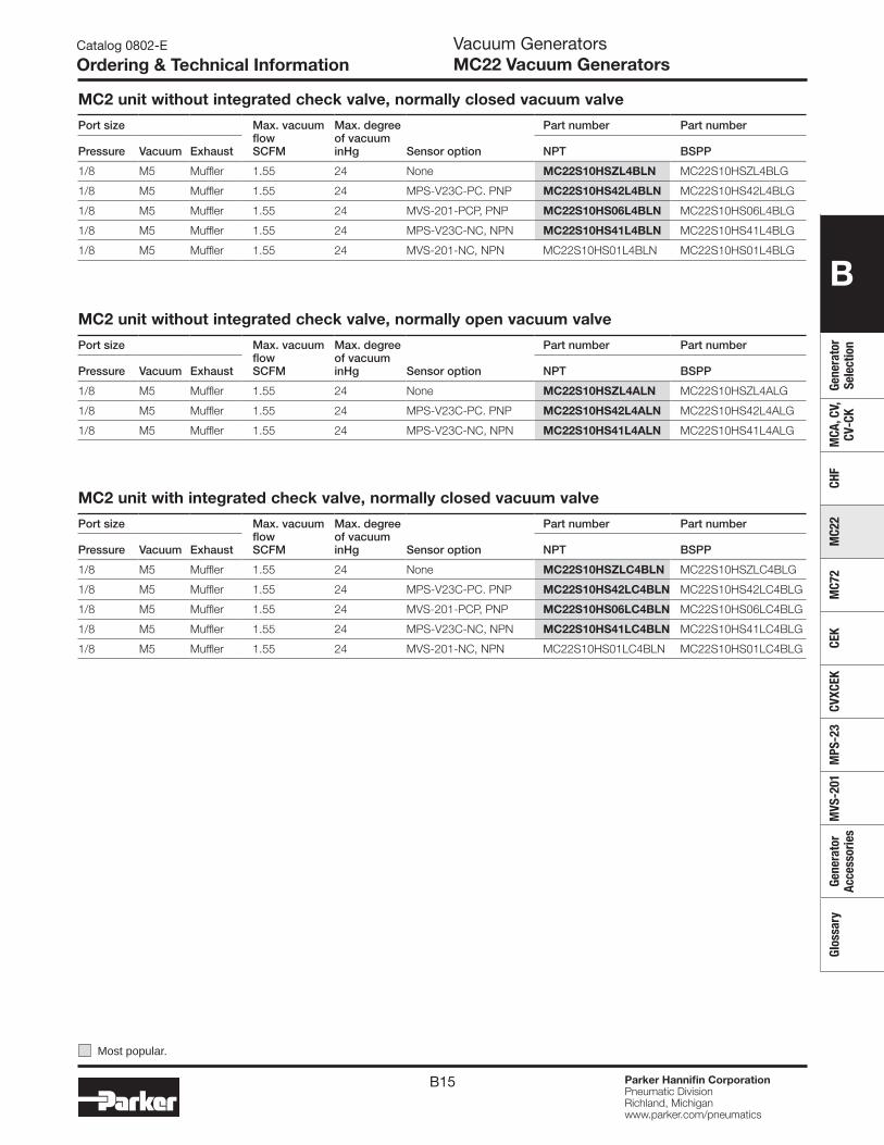
B15 Parker Hannifin CorporationPneumatic DivisionRichland, Michiganwww.parker.com/pneumatics
B
Gene
rato
r Se
lect
ion
MCA
, CV,
CV
-CK
CHF
MC2
2M
C72
CEK
CVXC
EKM
PS-2
3M
VS-2
01Ge
nera
tor
Acce
ssor
ies
Glos
sary
Catalog 0802-E
Ordering & Technical InformationVacuum GeneratorsMC22 Vacuum Generators
MC2 unit without integrated check valve, normally closed vacuum valve
Port size Max. vacuum flowSCFM
Max. degree of vacuuminHg Sensor option
Part number Part number
Pressure Vacuum Exhaust NPT BSPP
1/8 M5 Muffler 1.55 24 None MC22S10HSZL4BLN MC22S10HSZL4BLG
1/8 M5 Muffler 1.55 24 MPS-V23C-PC. PNP MC22S10HS42L4BLN MC22S10HS42L4BLG
1/8 M5 Muffler 1.55 24 MVS-201-PCP, PNP MC22S10HS06L4BLN MC22S10HS06L4BLG
1/8 M5 Muffler 1.55 24 MPS-V23C-NC, NPN MC22S10HS41L4BLN MC22S10HS41L4BLG
1/8 M5 Muffler 1.55 24 MVS-201-NC, NPN MC22S10HS01L4BLN MC22S10HS01L4BLG
MC2 unit without integrated check valve, normally open vacuum valve
Port size Max. vacuum flowSCFM
Max. degree of vacuuminHg Sensor option
Part number Part number
Pressure Vacuum Exhaust NPT BSPP
1/8 M5 Muffler 1.55 24 None MC22S10HSZL4ALN MC22S10HSZL4ALG
1/8 M5 Muffler 1.55 24 MPS-V23C-PC. PNP MC22S10HS42L4ALN MC22S10HS42L4ALG
1/8 M5 Muffler 1.55 24 MPS-V23C-NC, NPN MC22S10HS41L4ALN MC22S10HS41L4ALG
MC2 unit with integrated check valve, normally closed vacuum valve
Port size Max. vacuum flowSCFM
Max. degree of vacuuminHg Sensor option
Part number Part number
Pressure Vacuum Exhaust NPT BSPP
1/8 M5 Muffler 1.55 24 None MC22S10HSZLC4BLN MC22S10HSZLC4BLG
1/8 M5 Muffler 1.55 24 MPS-V23C-PC. PNP MC22S10HS42LC4BLN MC22S10HS42LC4BLG
1/8 M5 Muffler 1.55 24 MVS-201-PCP, PNP MC22S10HS06LC4BLN MC22S10HS06LC4BLG
1/8 M5 Muffler 1.55 24 MPS-V23C-NC, NPN MC22S10HS41LC4BLN MC22S10HS41LC4BLG
1/8 M5 Muffler 1.55 24 MVS-201-NC, NPN MC22S10HS01LC4BLN MC22S10HS01LC4BLG
Most popular.
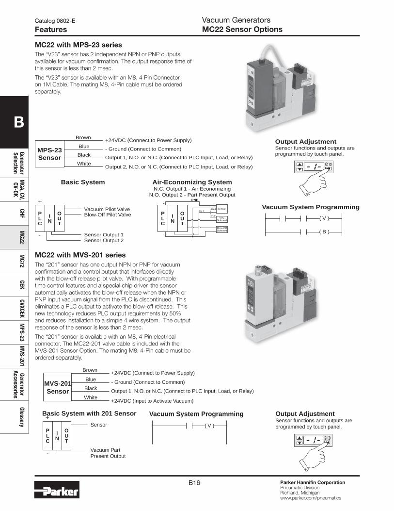
B16 Parker Hannifin CorporationPneumatic DivisionRichland, Michiganwww.parker.com/pneumatics
B
Generator Selection
MCA, CV,
CV-CKCHF
MC22
MC72
CEKCVXCEK
MPS-23
MVS-201
Generator Accessories
Glossary
The “V23” sensor has 2 independent NPN or PNP outputs available for vacuum confirmation. The output response time of this sensor is less than 2 msec.
The “V23” sensor is available with an M8, 4 Pin Connector, on 1M Cable. The mating M8, 4-Pin cable must be ordered separately.
The “201” sensor has one output NPN or PNP for vacuum confirmation and a control output that interfaces directly with the blow-off release pilot valve. With programmable time control features and a special chip driver, the sensor automatically activates the blow-off release when the NPN or PNP input vacuum signal from the PLC is discontinued. This eliminates a PLC output to activate the blow-off release. This new technology reduces PLC output requirements by 50% and reduces installation to a simple 4 wire system. The output response of the sensor is less than 2 msec.
The “201” sensor is available with an M8, 4-Pin electrical connector. The MC22-201 valve cable is included with the MVS-201 Sensor Option. The mating M8, 4-Pin cable must be ordered separately.
Catalog 0802-E
FeaturesVacuum GeneratorsMC22 Sensor Options
Basic System Air-Economizing System
PLC
IN
OUT
PLC
IN
OUT
-
+Vacuum Pilot ValveBlow-Off Pilot Valve
Sensor Output 1Sensor Output 2
Vacuum System Programming
MPS-23Sensor
Brown
Blue
Black
White
+24VDC (Connect to Power Supply)
- Ground (Connect to Common)
Output 1, N.O. or N.C. (Connect to PLC Input, Load, or Relay)
Output 2, N.O. or N.C. (Connect to PLC Input, Load, or Relay)
Output AdjustmentSensor functions and outputs areprogrammed by touch panel.
2 1
( V )
( B )
N.C. Output 1 - Air EconomizingN.O. Output 2 - Part Present Output
PNP
PNP
Out 2Out 1 Sensor
VACSolenoid
Blow-OffSolenoid
+
-
Vacuum System Programming
( V )
MVS-201Sensor
Brown
Blue
Black
White
+24VDC (Connect to Power Supply)
- Ground (Connect to Common)
Output 1, N.O. or N.C. (Connect to PLC Input, Load, or Relay)
+24VDC (Input to Activate Vacuum)
Output AdjustmentSensor functions and outputs areprogrammed by touch panel.
2 1
Basic System with 201 Sensor
PLC
IN
OUT
-
+Sensor
Vacuum PartPresent Output
MC22 with MPS-23 series
MC22 with MVS-201 series
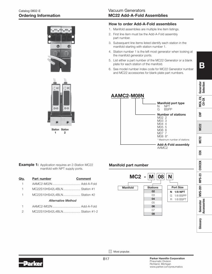
B17 Parker Hannifin CorporationPneumatic DivisionRichland, Michiganwww.parker.com/pneumatics
B
Gene
rato
r Se
lect
ion
MCA
, CV,
CV
-CK
CHF
MC2
2M
C72
CEK
CVXC
EKM
PS-2
3M
VS-2
01Ge
nera
tor
Acce
ssor
ies
Glos
sary
Station Station 1 2
Example 1: Application requires an 2-Station MC22 manifold with NPT supply ports.
Qty. Part number Comment
1 AAMC2-M02N ................................ Add-A-Fold
1 MC22S10HS42L4BLN .................... Station #1
1 MC22S10HS42L4BLN .................... Station #2
Alternative Method
1 AAMC2-M02N ................................ Add-A-Fold
2 MC22S10HS42L4BLN .................... Station #1-2
How to order Add-A-Fold assemblies1. Manifold assemblies are multiple line item listings.
2. First line item must be the Add-A-Fold assembly part number.
3. Subsequent line items listed identify each station in the manifold starting with station number 1.
4. Station number 1 is the left most generator when looking at the manifold generator ports.
5. List either a part number of the MC22 Generator or a blank plate for each station of the manifold.
6. See model number index code for MC22 Generator number and MC22 accessories for blank plate part numbers.
Catalog 0802-E
Ordering InformationVacuum GeneratorsMC22 Add-A-Fold Assemblies
MC2 - M 08 N
Manifold Port Size
N 1/8 NPT G 1/8 BSPP R 1/8 BSPT
Stations 02 03 04 05 06 07 08
Manifold part number
Most popular.
AAMC2-M08N Manifold port type N NPT G BSPP
Number of stations M02 2 M03 3 M04 4 M05 5 M06 6 M07 7 M08 8* * Maximum number of stations
Add-A-Fold assembly AAMC2
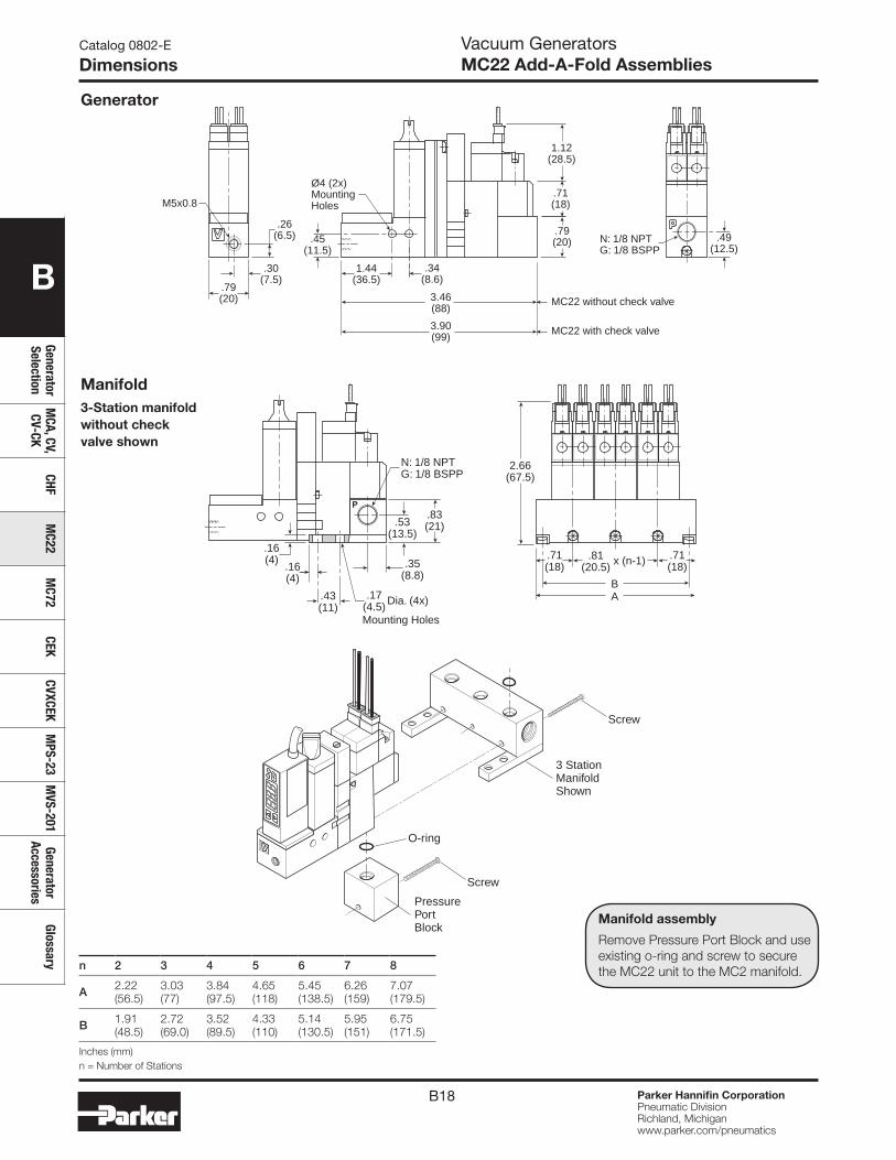
B18 Parker Hannifin CorporationPneumatic DivisionRichland, Michiganwww.parker.com/pneumatics
B
Generator Selection
MCA, CV,
CV-CKCHF
MC22
MC72
CEKCVXCEK
MPS-23
MVS-201
Generator Accessories
Glossary
Catalog 0802-E
DimensionsVacuum GeneratorsMC22 Add-A-Fold Assemblies
.71(18)
.26(6.5) .79
(20)
3.90(99)
3.46(88)
.79(20)
1.44(36.5)
.34(8.6)
.30(7.5)
1.12(28.5)
.45(11.5)
.49(12.5)
Ø4 (2x)MountingHoles M5x0.8
N: 1/8 NPTG: 1/8 BSPP
MC22 without check valve
MC22 with check valve
.16(4)
.16(4)
.35(8.8)
.43(11)
.71(18)
.81(20.5)
AB
.71(18)
.83(21)
2.66(67.5)
.53(13.5)
x (n-1)
.17(4.5) Dia. (4x)
N: 1/8 NPTG: 1/8 BSPP
Mounting Holes
n 2 3 4 5 6 7 8
A 2.22 (56.5)
3.03 (77)
3.84 (97.5)
4.65 (118)
5.45 (138.5)
6.26 (159)
7.07 (179.5)
B 1.91 (48.5)
2.72 (69.0)
3.52 (89.5)
4.33 (110)
5.14 (130.5)
5.95 (151)
6.75 (171.5)
Inches (mm)n = Number of Stations
Generator
Manifold3-Station manifold without check valve shown
3 StationManifoldShown
PressurePortBlock
Screw
O-ring
Screw
21
Manifold assembly
Remove Pressure Port Block and use existing o-ring and screw to secure the MC22 unit to the MC2 manifold.
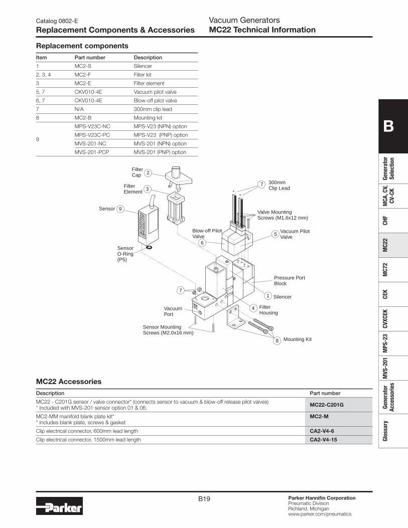
B19 Parker Hannifin CorporationPneumatic DivisionRichland, Michiganwww.parker.com/pneumatics
B
Gene
rato
r Se
lect
ion
MCA
, CV,
CV
-CK
CHF
MC2
2M
C72
CEK
CVXC
EKM
PS-2
3M
VS-2
01Ge
nera
tor
Acce
ssor
ies
Glos
sary
Vacuum PilotValve
300mmClip Lead
Blow-off PilotValve
VacuumPort
Sensor MountingScrews (M2.0x16 mm)
Valve MountingScrews (M1.6x12 mm)
5
FilterHousing
Mounting Kit
4
8
7Silencer
Pressure PortBlock
1
FilterElement 3
FilterCap 2
+- +-
21
Sensor 9
SensorO-Ring(P5)
7
6
Catalog 0802-E
Replacement Components & AccessoriesVacuum GeneratorsMC22 Technical Information
Replacement components
Item Part number Description
1 MC2-S Silencer
2, 3, 4 MC2-F Filter kit
3 MC2-E Filter element
5, 7 CKV010-4E Vacuum pilot valve
6, 7 CKV010-4E Blow-off pilot valve
7 N/A 300mm clip lead
8 MC2-B Mounting kit
9
MPS-V23C-NC MPS-V23 (NPN) option
MPS-V23C-PC MPS-V23 (PNP) option
MVS-201-NC MVS-201 (NPN) option
MVS-201-PCP MVS-201 (PNP) option
MC22 Accessories
Description Part number
MC22 - C201G sensor / valve connector* (connects sensor to vacuum & blow-off release pilot valves) * Included with MVS-201 sensor option 01 & 06. MC22-C201G
MC2-MM manifold blank plate kit* * includes blank plate, screws & gasket
MC2-M
Clip electrical connector, 600mm lead length CA2-V4-6
Clip electrical connector, 1500mm lead length CA2-V4-15
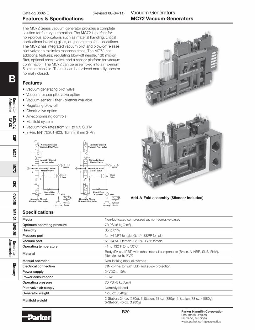
B20 Parker Hannifin CorporationPneumatic DivisionRichland, Michiganwww.parker.com/pneumatics
B
Generator Selection
MCA, CV,
CV-CKCHF
MC22
MC72
CEKCVXCEK
MPS-23
MVS-201
Generator Accessories
Glossary
Specifications
Media Non-lubricated compressed air, non-corrosive gases
Optimum operating pressure 70 PSI (5 kgf/cm2)
Humidity 35 to 85%
Pressure port N: 1/4 NPT female, G: 1/4 BSPP female
Vacuum port N: 1/4 NPT female, G: 1/4 BSPP female
Operating temperature 41 to 132°F (5 to 50°C)
Material Body (PA and PBT) with other internal components (Brass, AI.NBR, SUS, FKM), filter elements (PVF)
Manual operation Non-locking manual override
Electrical connection DIN connector with LED and surge protection
Power supply 24VDC ± 10%
Power consumption 1.8W
Operating pressure 70 PSI (5 kgf/cm2)
Pilot valve air supply Normally closed
Generator weight 12.0 oz. (340g)
Manifold weight 2-Station: 24 oz. (680g), 3-Station: 31 oz. (880g), 4-Station: 38 oz. (1080g), 5-Station: 45 oz. (1280g)
Features• Vacuum generating pilot valve• Vacuum release pilot valve option • Vacuum sensor - filter - silencer available • Regulating blow-off • Check valve option • Air-economizing controls• Manifold system • Vacuum flow rates from 2.1 to 5.5 SCFM• 3-Pin, EN175301-803, 15mm, 8mm 3-Pin
Catalog 0802-E
Features & SpecificationsVacuum GeneratorsMC72 Vacuum Generators
The MC72 Series vacuum generator provides a complete solution for factory automation. The MC72 is perfect for non-porous applications such as material handling, critical applications involving glass, or general transfer applications. The MC72 has integrated vacuum pilot and blow-off release pilot valves to minimize response times. The MC72 has additional features; regulating blow-off needle, 130 micron filter, optional check valve, and a sensor platform for vacuum confirmation. The MC72 can be assembled into a maximum 5 station manifold. The unit can be ordered normally open or normally closed.
Blow-off FlowAdjustment
OptionalSensor
Filter
CheckValve
Venturi
Normally ClosedBlow-off Pilot Valve
Normally ClosedVacuum Pilot Valve
Normally ClosedMaster Valve
Normally ClosedMaster Valve
Blow-off FlowAdjustment
Venturi
Normally ClosedBlow-off Pilot Valve
Normally ClosedVacuum Pilot Valve
Normally OpenMaster Valve
Normally ClosedMaster Valve
CheckValve
PFG Cup
OptionalSensor
Filter
PFG Cup
Add-A-Fold assembly (Silencer included)
(Revised 08-04-11)
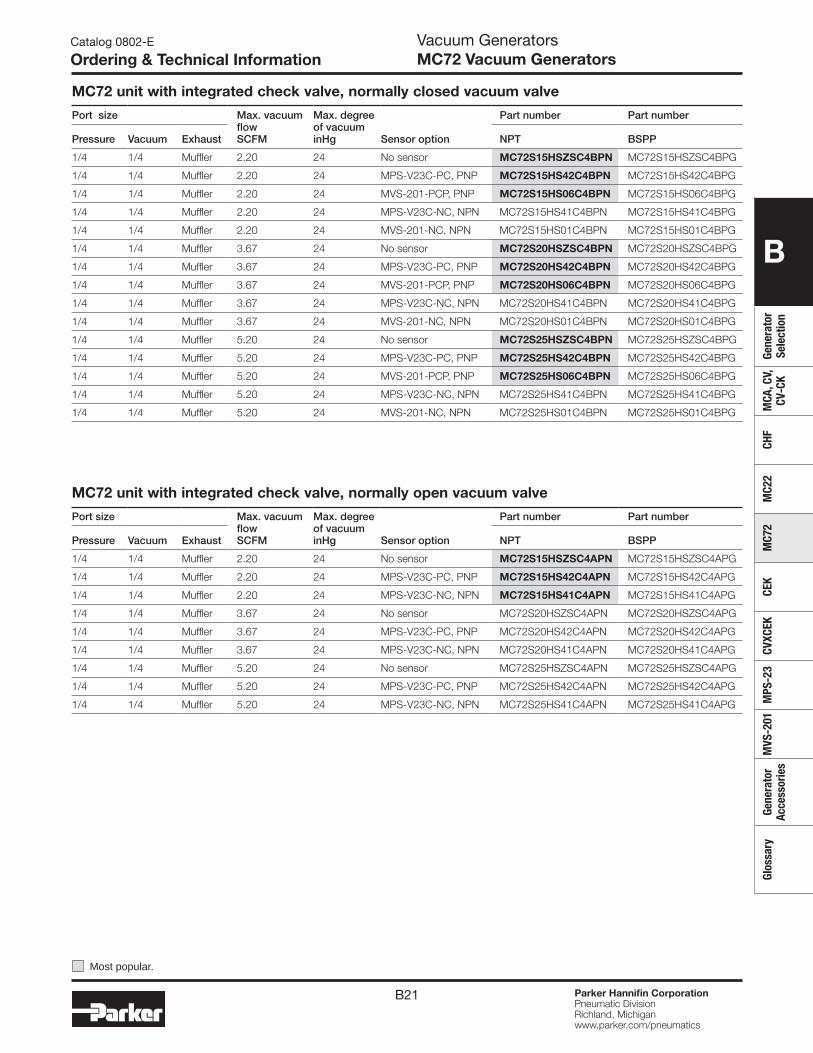
B21 Parker Hannifin CorporationPneumatic DivisionRichland, Michiganwww.parker.com/pneumatics
B
Gene
rato
r Se
lect
ion
MCA
, CV,
CV
-CK
CHF
MC2
2M
C72
CEK
CVXC
EKM
PS-2
3M
VS-2
01Ge
nera
tor
Acce
ssor
ies
Glos
sary
Catalog 0802-E
Ordering & Technical InformationVacuum GeneratorsMC72 Vacuum Generators
MC72 unit with integrated check valve, normally closed vacuum valve
Port size Max. vacuum flowSCFM
Max. degree of vacuuminHg Sensor option
Part number Part number
Pressure Vacuum Exhaust NPT BSPP
1/4 1/4 Muffler 2.20 24 No sensor MC72S15HSZSC4BPN MC72S15HSZSC4BPG
1/4 1/4 Muffler 2.20 24 MPS-V23C-PC, PNP MC72S15HS42C4BPN MC72S15HS42C4BPG
1/4 1/4 Muffler 2.20 24 MVS-201-PCP, PNP MC72S15HS06C4BPN MC72S15HS06C4BPG
1/4 1/4 Muffler 2.20 24 MPS-V23C-NC, NPN MC72S15HS41C4BPN MC72S15HS41C4BPG
1/4 1/4 Muffler 2.20 24 MVS-201-NC, NPN MC72S15HS01C4BPN MC72S15HS01C4BPG
1/4 1/4 Muffler 3.67 24 No sensor MC72S20HSZSC4BPN MC72S20HSZSC4BPG
1/4 1/4 Muffler 3.67 24 MPS-V23C-PC, PNP MC72S20HS42C4BPN MC72S20HS42C4BPG
1/4 1/4 Muffler 3.67 24 MVS-201-PCP, PNP MC72S20HS06C4BPN MC72S20HS06C4BPG
1/4 1/4 Muffler 3.67 24 MPS-V23C-NC, NPN MC72S20HS41C4BPN MC72S20HS41C4BPG
1/4 1/4 Muffler 3.67 24 MVS-201-NC, NPN MC72S20HS01C4BPN MC72S20HS01C4BPG
1/4 1/4 Muffler 5.20 24 No sensor MC72S25HSZSC4BPN MC72S25HSZSC4BPG
1/4 1/4 Muffler 5.20 24 MPS-V23C-PC, PNP MC72S25HS42C4BPN MC72S25HS42C4BPG
1/4 1/4 Muffler 5.20 24 MVS-201-PCP, PNP MC72S25HS06C4BPN MC72S25HS06C4BPG
1/4 1/4 Muffler 5.20 24 MPS-V23C-NC, NPN MC72S25HS41C4BPN MC72S25HS41C4BPG
1/4 1/4 Muffler 5.20 24 MVS-201-NC, NPN MC72S25HS01C4BPN MC72S25HS01C4BPG
MC72 unit with integrated check valve, normally open vacuum valve
Port size Max. vacuum flowSCFM
Max. degree of vacuuminHg Sensor option
Part number Part number
Pressure Vacuum Exhaust NPT BSPP
1/4 1/4 Muffler 2.20 24 No sensor MC72S15HSZSC4APN MC72S15HSZSC4APG
1/4 1/4 Muffler 2.20 24 MPS-V23C-PC, PNP MC72S15HS42C4APN MC72S15HS42C4APG
1/4 1/4 Muffler 2.20 24 MPS-V23C-NC, NPN MC72S15HS41C4APN MC72S15HS41C4APG
1/4 1/4 Muffler 3.67 24 No sensor MC72S20HSZSC4APN MC72S20HSZSC4APG
1/4 1/4 Muffler 3.67 24 MPS-V23C-PC, PNP MC72S20HS42C4APN MC72S20HS42C4APG
1/4 1/4 Muffler 3.67 24 MPS-V23C-NC, NPN MC72S20HS41C4APN MC72S20HS41C4APG
1/4 1/4 Muffler 5.20 24 No sensor MC72S25HSZSC4APN MC72S25HSZSC4APG
1/4 1/4 Muffler 5.20 24 MPS-V23C-PC, PNP MC72S25HS42C4APN MC72S25HS42C4APG
1/4 1/4 Muffler 5.20 24 MPS-V23C-NC, NPN MC72S25HS41C4APN MC72S25HS41C4APG
Most popular.
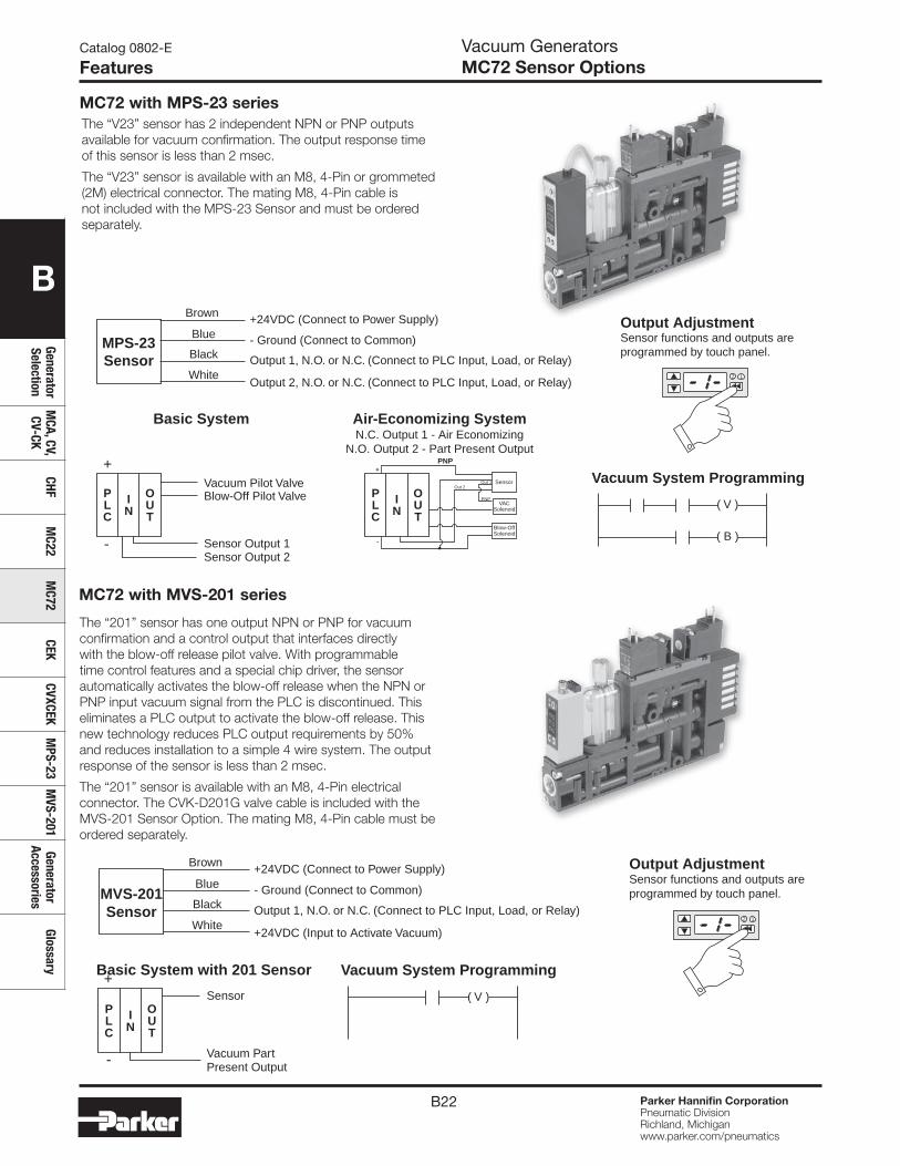
B22 Parker Hannifin CorporationPneumatic DivisionRichland, Michiganwww.parker.com/pneumatics
B
Generator Selection
MCA, CV,
CV-CKCHF
MC22
MC72
CEKCVXCEK
MPS-23
MVS-201
Generator Accessories
Glossary
Basic System Air-Economizing System
PLC
IN
OUT
PLC
IN
OUT
-
+Vacuum Pilot ValveBlow-Off Pilot Valve
Sensor Output 1Sensor Output 2
Vacuum System Programming
MPS-23Sensor
Brown
Blue
Black
White
+24VDC (Connect to Power Supply)
- Ground (Connect to Common)
Output 1, N.O. or N.C. (Connect to PLC Input, Load, or Relay)
Output 2, N.O. or N.C. (Connect to PLC Input, Load, or Relay)
Output AdjustmentSensor functions and outputs areprogrammed by touch panel.
2 1
( V )
( B )
N.C. Output 1 - Air EconomizingN.O. Output 2 - Part Present Output
PNP
PNP
Out 2Out 1 Sensor
VACSolenoid
Blow-OffSolenoid
+
-
Vacuum System Programming
( V )
MVS-201Sensor
Brown
Blue
Black
White
+24VDC (Connect to Power Supply)
- Ground (Connect to Common)
Output 1, N.O. or N.C. (Connect to PLC Input, Load, or Relay)
+24VDC (Input to Activate Vacuum)
Output AdjustmentSensor functions and outputs areprogrammed by touch panel.
2 1
Basic System with 201 Sensor
PLC
IN
OUT
-
+Sensor
Vacuum PartPresent Output
Catalog 0802-E
FeaturesVacuum GeneratorsMC72 Sensor Options
MC72 with MPS-23 series
MC72 with MVS-201 series
The “V23” sensor has 2 independent NPN or PNP outputs available for vacuum confirmation. The output response time of this sensor is less than 2 msec.
The “V23” sensor is available with an M8, 4-Pin or grommeted (2M) electrical connector. The mating M8, 4-Pin cable is not included with the MPS-23 Sensor and must be ordered separately.
The “201” sensor has one output NPN or PNP for vacuum confirmation and a control output that interfaces directly with the blow-off release pilot valve. With programmable time control features and a special chip driver, the sensor automatically activates the blow-off release when the NPN or PNP input vacuum signal from the PLC is discontinued. This eliminates a PLC output to activate the blow-off release. This new technology reduces PLC output requirements by 50% and reduces installation to a simple 4 wire system. The output response of the sensor is less than 2 msec.
The “201” sensor is available with an M8, 4-Pin electrical connector. The CVK-D201G valve cable is included with the MVS-201 Sensor Option. The mating M8, 4-Pin cable must be ordered separately.
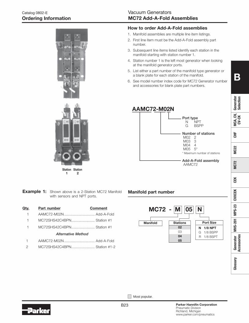
B23 Parker Hannifin CorporationPneumatic DivisionRichland, Michiganwww.parker.com/pneumatics
B
Gene
rato
r Se
lect
ion
MCA
, CV,
CV
-CK
CHF
MC2
2M
C72
CEK
CVXC
EKM
PS-2
3M
VS-2
01Ge
nera
tor
Acce
ssor
ies
Glos
sary
Catalog 0802-E
Ordering InformationVacuum GeneratorsMC72 Add-A-Fold Assemblies
Station Station 1 2
Example 1: Shown above is a 2-Station MC72 Manifold with sensors and NPT ports.
Qty. Part number Comment
1 AAMC72-M02N .............................. Add-A-Fold
1 MC72SHS42C4BPN ....................... Station #1
1 MC72SHS42C4BPN ....................... Station #1
Alternative Method
1 AAMC72-M02N .............................. Add-A-Fold
2 MC72SHS42C4BPN ....................... Station #1-2
How to order Add-A-Fold assemblies1. Manifold assemblies are multiple line item listings.
2. First line item must be the Add-A-Fold assembly part number.
3. Subsequent line items listed identify each station in the manifold starting with station number 1.
4. Station number 1 is the left most generator when looking at the manifold generator ports.
5. List either a part number of the manifold type generator or a blank plate for each station of the manifold.
6. See model number index code for MC72 Generator number and accessories for blank plate part numbers.
MC72 - M 05 N
Manifold Port Size
N 1/8 NPT G 1/8 BSPP R 1/8 BSPT
Stations 02 03 04 05
Manifold part number
Most popular.
AAMC72-M02N Port type N NPT G BSPP
Number of stations M02 2 M03 3 M04 4 M05 5* * Maximum number of stations
Add-A-Fold assembly AAMC72
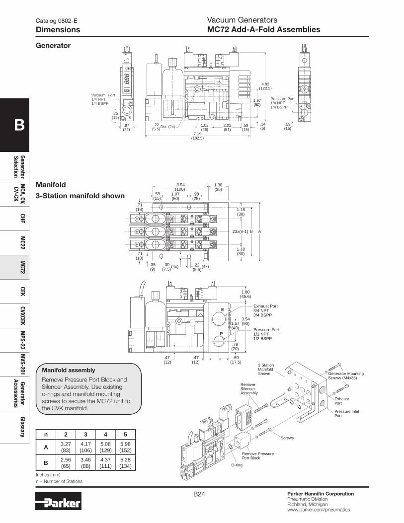
B24 Parker Hannifin CorporationPneumatic DivisionRichland, Michiganwww.parker.com/pneumatics
B
Generator Selection
MCA, CV,
CV-CKCHF
MC22
MC72
CEKCVXCEK
MPS-23
MVS-201
Generator Accessories
Glossary
Pressure InletPort
Exhaust Port
Generator MountingScrews (M4x35)
RemoveSilencerAssembly
Remove PressurePort Block
3 StationManifoldShown
O-ring
Screws
0
1
1
01
1
Catalog 0802-E
DimensionsVacuum GeneratorsMC72 Add-A-Fold Assemblies
Generator
.71(18)
.71(18) 1.18
(30)
1.18(30)
AB23x(n-1)
.59(15)
.98(25)
1.97(50)
3.94(100)
.35(9)
.30(7.5)
1.38(35)
.22 (5.5)
(4x)(4x)
1.57(40)
.69(17.5)
.79(20)
3.54(90)
Exhaust Port3/4 NPT3/4 BSPP
Pressure Port1/2 NPT1/2 BSPP
.47 (12)
.47(12)
1.80(45.6)
E
P
01
1
01
1
01
1
01
1
01
1
01
1
Manifold
3-Station manifold shown
Manifold assembly
Remove Pressure Port Block and Silencer Assembly. Use existing o-rings and manifold mounting screws to secure the MC72 unit to the CVK manifold.
21 M
OD
E
2.01(51)
.59(15)
1.02(26)
.87(22)
.75(19)
7.19(182.5)
4.82(122.5)
1.97(50)
.24(6)
.59(15)
Pressure Port1/4 NPT1/4 BSPP
Vacuum Port1/4 NPT1/4 BSPP
.22(5.5)Dia. (2x)
n 2 3 4 5
A 3.27(83)
4.17(106)
5.08(129)
5.98(152)
B 2.56(65)
3.46(88)
4.37(111)
5.28(134)
Inches (mm)n = Number of Stations
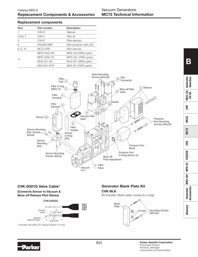
B25 Parker Hannifin CorporationPneumatic DivisionRichland, Michiganwww.parker.com/pneumatics
B
Gene
rato
r Se
lect
ion
MCA
, CV,
CV
-CK
CHF
MC2
2M
C72
CEK
CVXC
EKM
PS-2
3M
VS-2
01Ge
nera
tor
Acce
ssor
ies
Glos
sary
CVK-D201G
6"(152 mm)
9"(229 mm)
VacuumValve
VacuumBlow-off Valve
CVK-D201G Valve Cable*(Connects Sensor to Vacuum & Blow-off Release Pilot Valves)
Generator Blank Plate KitCVK-BLK Kit includes: Blank plate, screws & o-rings
Catalog 0802-E
Replacement Components & Accessories Vacuum GeneratorsMC72 Technical Information
Replacement components
Item Part number Description
1 CVK-S Silencer
2 thru 7 CVK-F Filter kit
5 CVK-E Filter element
8 PS294679BP DIN connector with LED
8, 9, 10 MC72-4PD Pilot valve kit
11
MPS-V23C-NC MPS-V23 (NPN) option
MPS-V23C-PC MPS-V23 (PNP) option
MVS-201-NC MVS-201 (NPN) option
MVS-201-PCP MVS-201 (PNP) option
Sensor
SensorO-Ring(P5)
SensorMountingBrkt.
Sensor MountingBrkt. Screws(M3x6)
Sensor MountingScrews (M2x6)
VacuumPort
PressurePort MountingScrews (M4x35)
FilterBase
Blow-off PilotValve
Vacuum PilotValve
Blow-offFlow Adjustment
DINConnector
9
FilterElement
FilterGasket
5
11
6
7
3
FilterCap
Filter O-ring(M8x1.0)
4FilterHousing
2
Valve MountingScrews (M3x18)
9
10
1
8
Silencer
Pressure PortO-Ring (M14x1.5)
Pressure PortBlock
Gasket
01
10
11
Mounting Screws(M4x35)
BlankPlate
O-rings
* Included with MVS-201 Sensor Option 01 & 06.
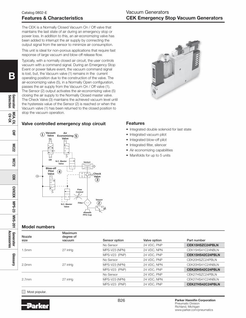
B26 Parker Hannifin CorporationPneumatic DivisionRichland, Michiganwww.parker.com/pneumatics
B
Generator Selection
MCA, CV,
CV-CKCHF
MC22
MC72
CEKCVXCEK
MPS-23
MVS-201
Generator Accessories
Glossary
The CEK is a Normally Closed Vacuum On / Off valve that maintains the last state of air during an emergency stop or power loss. In addition to this, an air-economizing valve has been added to interrupt the air supply by connecting the output signal from the sensor to minimize air consumption.
This unit is ideal for non-porous applications that require fast response of large vacuum and blow-off release flow.
Typically, with a normally closed air circuit, the user controls vacuum with a command signal. During an Emergency Stop Event or power failure event, the vacuum command signal is lost, but, the Vacuum valve (1) remains in the current operating position due to the construction of the valve. The air-economizing valve (5), in a Normally Open configuration, passes the air supply from the Vacuum On / Off valve (1). The Sensor (2) output activates the air-economizing valve (5) closing the air supply to the Normally Closed master valve. The Check Valve (3) maintains the achieved vacuum level until the hysteresis value of the Sensor (2) is reached or when the Vacuum valve (1) has been returned to the closed position to stop the vacuum operation.
Catalog 0802-E
Features & CharacteristicsVacuum GeneratorsCEK Emergency Stop Vacuum Generators
Features• Integrated double solenoid for last state • Integrated vacuum pilot• Integrated blow-off pilot • Integrated filter, silencer• Air economizing capabilities• Manifolds for up to 5 units
PFG Cup
On
Off
AirEconomizing
Valve
VacuumValve
CheckValve
Sensor
VenturiN.C. MasterValve
N.C. MasterValve
Blow-offPilotValve
Filter
FlowControl
1 5
4
3
2
Valve controlled emergency stop circuit
Model numbers
Nozzle size
Maximum degree of vacuum Sensor option Valve option Part number
1.5mm 27 inHg
No Sensor 24 VDC, PNP CEK15HSZC24PBLN
MPS-V23 (NPN) 24 VDC, NPN CEK15HS41C24NBLN
MPS-V23 (PNP) 24 VDC, PNP CEK15HS42C24PBLN
2.0mm 27 inHg
No Sensor 24 VDC, PNP CEK20HSZC24PBLN
MPS-V23 (NPN) 24 VDC, NPN CEK20HS41C24NBLN
MPS-V23 (PNP) 24 VDC, PNP CEK20HS42C24PBLN
2.7mm 27 inHg
No Sensor 24 VDC, PNP CEK27HSZC24PBLN
MPS-V23 (NPN) 24 VDC, NPN CEK27HS41C24NBLN
MPS-V23 (PNP) 24 VDC, PNP CEK27HS42C24PBLN
Most popular.
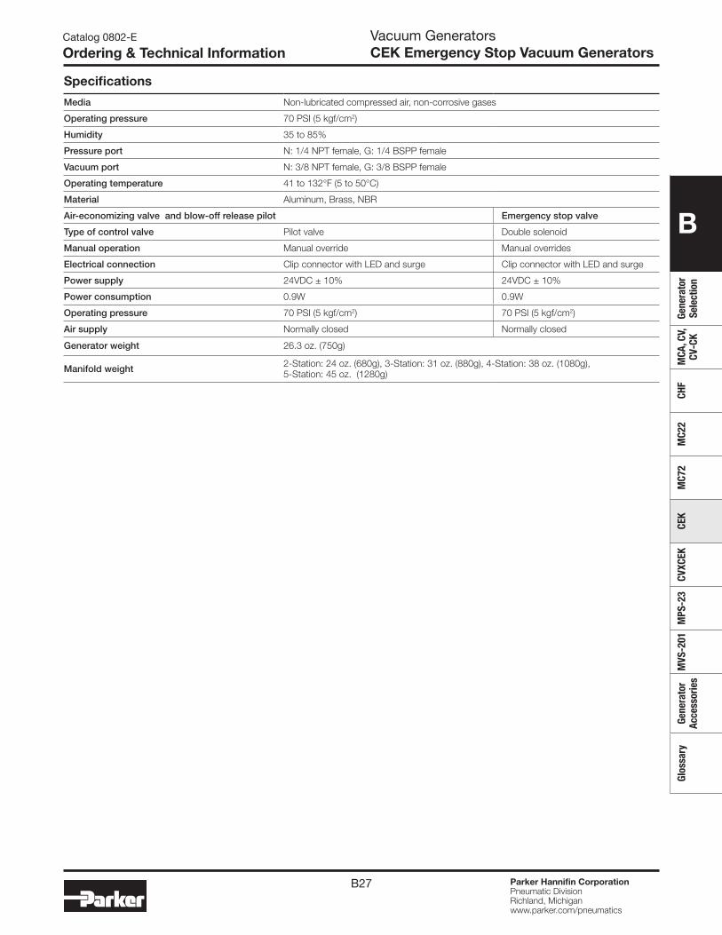
B27 Parker Hannifin CorporationPneumatic DivisionRichland, Michiganwww.parker.com/pneumatics
B
Gene
rato
r Se
lect
ion
MCA
, CV,
CV
-CK
CHF
MC2
2M
C72
CEK
CVXC
EKM
PS-2
3M
VS-2
01Ge
nera
tor
Acce
ssor
ies
Glos
sary
Vacuum GeneratorsCEK Emergency Stop Vacuum Generators
Specifications
Media Non-lubricated compressed air, non-corrosive gases
Operating pressure 70 PSI (5 kgf/cm2)
Humidity 35 to 85%
Pressure port N: 1/4 NPT female, G: 1/4 BSPP female
Vacuum port N: 3/8 NPT female, G: 3/8 BSPP female
Operating temperature 41 to 132°F (5 to 50°C)
Material Aluminum, Brass, NBR
Air-economizing valve and blow-off release pilot Emergency stop valve
Type of control valve Pilot valve Double solenoid
Manual operation Manual override Manual overrides
Electrical connection Clip connector with LED and surge Clip connector with LED and surge
Power supply 24VDC ± 10% 24VDC ± 10%
Power consumption 0.9W 0.9W
Operating pressure 70 PSI (5 kgf/cm2) 70 PSI (5 kgf/cm2)
Air supply Normally closed Normally closed
Generator weight 26.3 oz. (750g)
Manifold weight 2-Station: 24 oz. (680g), 3-Station: 31 oz. (880g), 4-Station: 38 oz. (1080g), 5-Station: 45 oz. (1280g)
Catalog 0802-E
Ordering & Technical Information
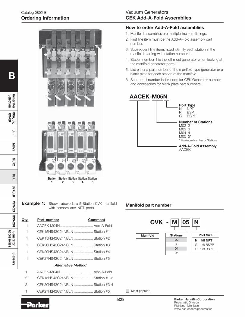
B28 Parker Hannifin CorporationPneumatic DivisionRichland, Michiganwww.parker.com/pneumatics
B
Generator Selection
MCA, CV,
CV-CKCHF
MC22
MC72
CEKCVXCEK
MPS-23
MVS-201
Generator Accessories
Glossary
Catalog 0802-E
Ordering InformationVacuum GeneratorsCEK Add-A-Fold Assemblies
Station Station Station Station Station 1 2 3 4 5
Example 1: Shown above is a 5-Station CVK manifold with sensors and NPT ports.
Qty. Part number Comment
1 AACEK-M04N ................................. Add-A-Fold
1 CEK15HS42C24NBLN ................... Station #1
1 CEK15HS42C24NBLN ................... Station #2
1 CEK20HS42C24NBLN ................... Station #3
1 CEK20HS42C24NBLN ................... Station #4
1 CEK27HS42C24NBLN ................... Station #5
Alternative Method
1 AACEK-M04N ................................. Add-A-Fold
2 CEK15HS42C24NBLN ................... Station #1-2
2 CEK20HS42C24NBLN ................... Station #3-4
1 CEK27HS42C24NBLN ................... Station #5
How to order Add-A-Fold assemblies1. Manifold assemblies are multiple line item listings.
2. First line item must be the Add-A-Fold assembly part number.
3. Subsequent line items listed identify each station in the manifold starting with station number 1.
4. Station number 1 is the left most generator when looking at the manifold generator ports.
5. List either a part number of the manifold type generator or a blank plate for each station of the manifold.
6. See model number index code for CEK Generator number and accessories for blank plate part numbers.
CVK - M 05 N
Manifold Port Size
N 1/8 NPT G 1/8 BSPP R 1/8 BSPT
Stations 02 03 04 05
Manifold part number
Most popular.
AACEK-M05N Port Type N NPT R BSP G BSPP
Number of Stations M02 2 M03 3 M04 4 M05 5* * Maximum Number of Stations
Add-A-Fold Assembly AACEK
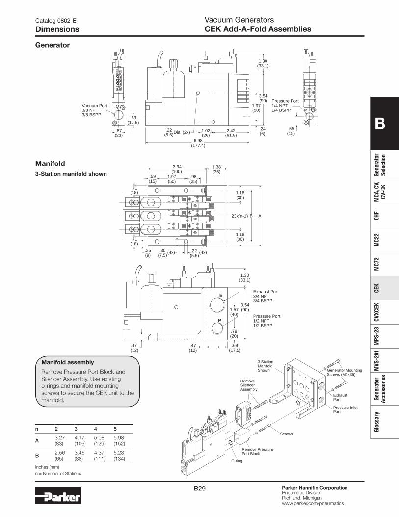
B29 Parker Hannifin CorporationPneumatic DivisionRichland, Michiganwww.parker.com/pneumatics
B
Gene
rato
r Se
lect
ion
MCA
, CV,
CV
-CK
CHF
MC2
2M
C72
CEK
CVXC
EKM
PS-2
3M
VS-2
01Ge
nera
tor
Acce
ssor
ies
Glos
sary
Catalog 0802-E
DimensionsVacuum GeneratorsCEK Add-A-Fold Assemblies
Pressure InletPort
Exhaust Port
Generator MountingScrews (M4x35)
RemoveSilencerAssembly
Remove PressurePort Block
3 StationManifoldShown
O-ring
Screws
12 M
OD
E
.87(22)
2.42(61.5)
6.98(177.4)
1.02(26)
.22(5.5)
1.30(33.1)
3.54(90)
1.97(50)
.69(17.5)
.24(6)
.59(15)Dia. (2x)
Vacuum Port3/8 NPT3/8 BSPP
Pressure Port1/4 NPT1/4 BSPP
Generator
.71(18)
.71(18) 1.18
(30)
1.18(30)
AB23x(n-1)
1.57(40)
.69(17.5)
.79(20)
3.54(90)
.59(15)
.98(25)
1.97(50)
3.94(100)
.35(9)
.30(7.5)
1.38(35)
Exhaust Port3/4 NPT3/4 BSPP
Pressure Port1/2 NPT1/2 BSPP
.22 (5.5)
(4x)(4x)
.47 (12)
.47(12)
E
P
1.30(33.1)
Manifold3-Station manifold shown
Manifold assembly
Remove Pressure Port Block and Silencer Assembly. Use existing o-rings and manifold mounting screws to secure the CEK unit to the manifold.
n 2 3 4 5
A 3.27(83)
4.17(106)
5.08(129)
5.98(152)
B 2.56(65)
3.46(88)
4.37(111)
5.28(134)
Inches (mm)n = Number of Stations
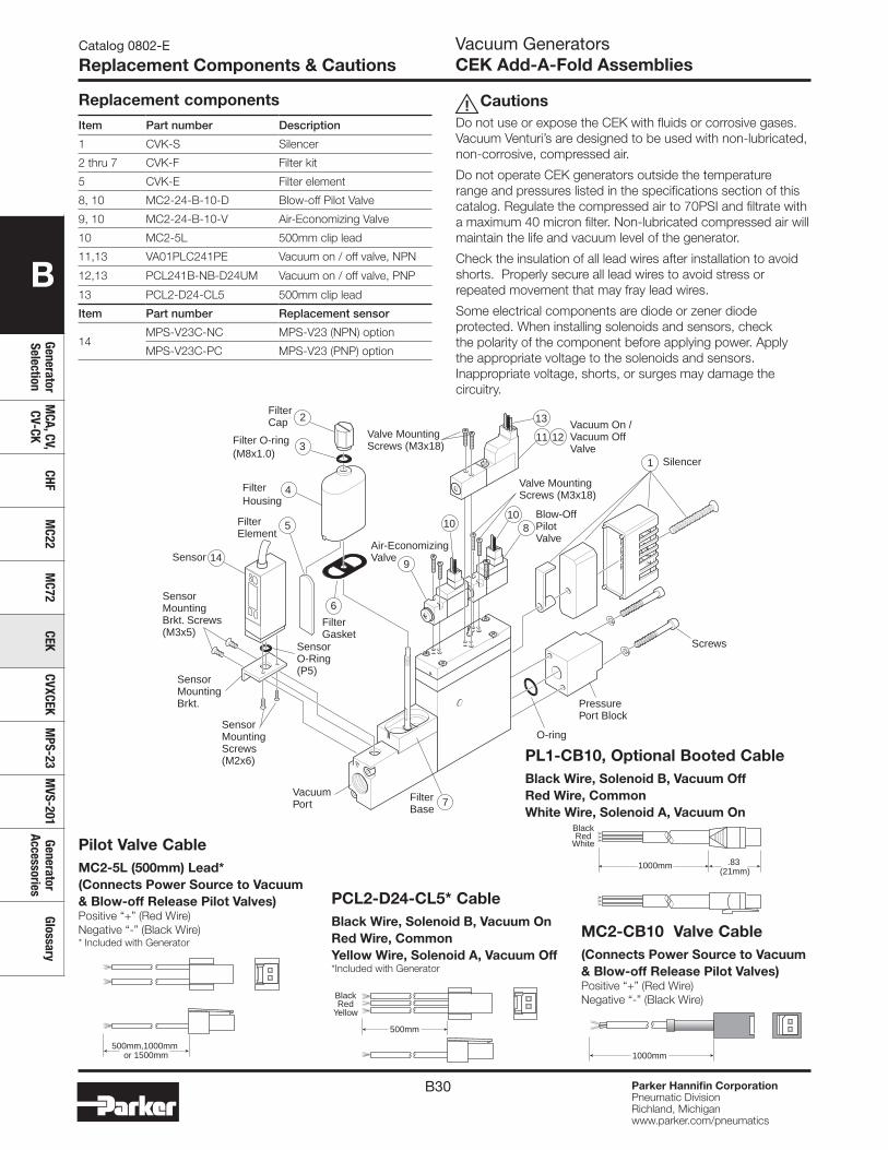
B30 Parker Hannifin CorporationPneumatic DivisionRichland, Michiganwww.parker.com/pneumatics
B
Generator Selection
MCA, CV,
CV-CKCHF
MC22
MC72
CEKCVXCEK
MPS-23
MVS-201
Generator Accessories
Glossary
Catalog 0802-E
Replacement Components & CautionsVacuum GeneratorsCEK Add-A-Fold Assemblies
Replacement components
Item Part number Description
1 CVK-S Silencer
2 thru 7 CVK-F Filter kit
5 CVK-E Filter element
8, 10 MC2-24-B-10-D Blow-off Pilot Valve
9, 10 MC2-24-B-10-V Air-Economizing Valve
10 MC2-5L 500mm clip lead
11,13 VA01PLC241PE Vacuum on / off valve, NPN
12,13 PCL241B-NB-D24UM Vacuum on / off valve, PNP
13 PCL2-D24-CL5 500mm clip lead
Item Part number Replacement sensor
14MPS-V23C-NC MPS-V23 (NPN) option
MPS-V23C-PC MPS-V23 (PNP) option
CautionsDo not use or expose the CEK with fluids or corrosive gases. Vacuum Venturi’s are designed to be used with non-lubricated, non-corrosive, compressed air.
Do not operate CEK generators outside the temperature range and pressures listed in the specifications section of this catalog. Regulate the compressed air to 70PSI and filtrate with a maximum 40 micron filter. Non-lubricated compressed air will maintain the life and vacuum level of the generator.
Check the insulation of all lead wires after installation to avoid shorts. Properly secure all lead wires to avoid stress or repeated movement that may fray lead wires.
Some electrical components are diode or zener diode protected. When installing solenoids and sensors, check the polarity of the component before applying power. Apply the appropriate voltage to the solenoids and sensors. Inappropriate voltage, shorts, or surges may damage the circuitry.
Sensor
SensorO-Ring(P5)
SensorMountingBrkt.
SensorMountingBrkt. Screws(M3x5)
SensorMountingScrews(M2x6)
VacuumPort
FilterBase
FilterElement
FilterGasket
5
14
6
7
3
FilterCap
Filter O-ring(M8x1.0)
4FilterHousing
2
Valve MountingScrews (M3x18)
1 Silencer
Blow-OffPilotValve
Vacuum On /Vacuum OffValve
810
10
Air-EconomizingValve
9
11 12
13
Valve MountingScrews (M3x18)
PressurePort Block
O-ring
Screws
!
500mm
RedYellow
Black
PCL2-D24-CL5* CableBlack Wire, Solenoid B, Vacuum OnRed Wire, CommonYellow Wire, Solenoid A, Vacuum Off*Included with Generator
500mm,1000mm or 1500mm
Pilot Valve CableMC2-5L (500mm) Lead*(Connects Power Source to Vacuum & Blow-off Release Pilot Valves)Positive “+” (Red Wire)Negative “-” (Black Wire)* Included with Generator
1000mm
BlackRed
White
.83 (21mm)
MC2-CB10 Valve Cable(Connects Power Source to Vacuum & Blow-off Release Pilot Valves)Positive “+” (Red Wire)Negative “-” (Black Wire)
1000mm
PL1-CB10, Optional Booted CableBlack Wire, Solenoid B, Vacuum OffRed Wire, CommonWhite Wire, Solenoid A, Vacuum On
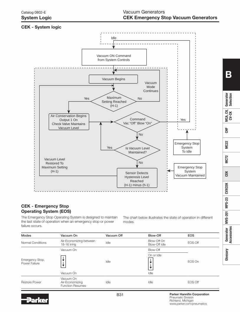
B31 Parker Hannifin CorporationPneumatic DivisionRichland, Michiganwww.parker.com/pneumatics
B
Gene
rato
r Se
lect
ion
MCA
, CV,
CV
-CK
CHF
MC2
2M
C72
CEK
CVXC
EKM
PS-2
3M
VS-2
01Ge
nera
tor
Acce
ssor
ies
Glos
sary
CEK - Emergency Stop Operating System (EOS)The Emergency Stop Operating System is designed to maintain the last state of operation when an emergency stop or power failure occurs.
Modes Vacuum On Vacuum Off Blow-Off EOS
Normal Conditions Air-Economizing between18-16 inHg Idle Blow-Off On
Blow-Off Idle EOS Off
Emergency Stop,Power Failure
Vacuum On
Idle
Blow-Off
EOS On
On or Idle
Vacuum On Idle
Restore PowerVacuum On Air-Economizing Function Resumes
Idle Idle EOS Off
Catalog 0802-E
System LogicVacuum GeneratorsCEK Emergency Stop Vacuum Generators
CEK - System logic
Vacuum ON Commandfrom System Controls
Idle
Vacuum BeginsVacuumMode
Continues
MaximumSetting Reached
(H-1)
Yes
Yes
Yes
No
No
CommandVac “Off” Blow “On”
No
Is Vacuum LevelMaintained?
Air Conservation BeginsOutput 1 On
Check Valve MaintainsVacuum Level
Sensor DetectsHysteresis Level
Reached(H-1) minus (h-1)
Vacuum LevelRestored To
Maximum Setting(H-1)
Emergency StopSystemTo Idle
Emergency StopSystem
Vacuum Maintained
The chart below illustrates the state of operation in different modes.
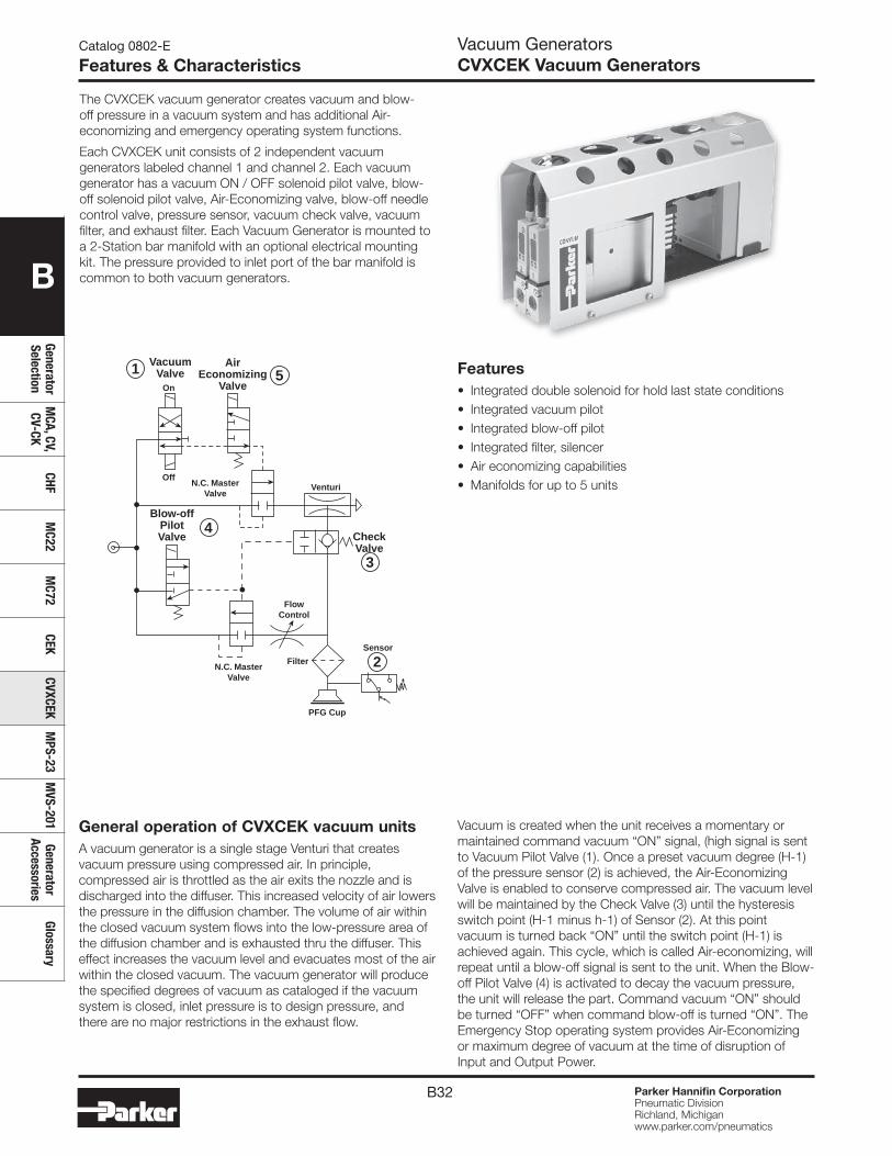
B32 Parker Hannifin CorporationPneumatic DivisionRichland, Michiganwww.parker.com/pneumatics
B
Generator Selection
MCA, CV,
CV-CKCHF
MC22
MC72
CEKCVXCEK
MPS-23
MVS-201
Generator Accessories
Glossary
Catalog 0802-E
Features & CharacteristicsVacuum GeneratorsCVXCEK Vacuum Generators
The CVXCEK vacuum generator creates vacuum and blow-off pressure in a vacuum system and has additional Air-economizing and emergency operating system functions.
Each CVXCEK unit consists of 2 independent vacuum generators labeled channel 1 and channel 2. Each vacuum generator has a vacuum ON / OFF solenoid pilot valve, blow-off solenoid pilot valve, Air-Economizing valve, blow-off needle control valve, pressure sensor, vacuum check valve, vacuum filter, and exhaust filter. Each Vacuum Generator is mounted to a 2-Station bar manifold with an optional electrical mounting kit. The pressure provided to inlet port of the bar manifold is common to both vacuum generators.
PFG Cup
On
Off
AirEconomizing
Valve
VacuumValve
CheckValve
Sensor
VenturiN.C. MasterValve
N.C. MasterValve
Blow-offPilotValve
Filter
FlowControl
1 5
4
3
2
General operation of CVXCEK vacuum unitsA vacuum generator is a single stage Venturi that creates vacuum pressure using compressed air. In principle, compressed air is throttled as the air exits the nozzle and is discharged into the diffuser. This increased velocity of air lowers the pressure in the diffusion chamber. The volume of air within the closed vacuum system flows into the low-pressure area of the diffusion chamber and is exhausted thru the diffuser. This effect increases the vacuum level and evacuates most of the air within the closed vacuum. The vacuum generator will produce the specified degrees of vacuum as cataloged if the vacuum system is closed, inlet pressure is to design pressure, and there are no major restrictions in the exhaust flow.
Vacuum is created when the unit receives a momentary or maintained command vacuum “ON” signal, (high signal is sent to Vacuum Pilot Valve (1). Once a preset vacuum degree (H-1) of the pressure sensor (2) is achieved, the Air-Economizing Valve is enabled to conserve compressed air. The vacuum level will be maintained by the Check Valve (3) until the hysteresis switch point (H-1 minus h-1) of Sensor (2). At this point vacuum is turned back “ON” until the switch point (H-1) is achieved again. This cycle, which is called Air-economizing, will repeat until a blow-off signal is sent to the unit. When the Blow-off Pilot Valve (4) is activated to decay the vacuum pressure, the unit will release the part. Command vacuum “ON” should be turned “OFF” when command blow-off is turned “ON”. The Emergency Stop operating system provides Air-Economizing or maximum degree of vacuum at the time of disruption of Input and Output Power.
Features• Integrated double solenoid for hold last state conditions • Integrated vacuum pilot• Integrated blow-off pilot • Integrated filter, silencer• Air economizing capabilities• Manifolds for up to 5 units
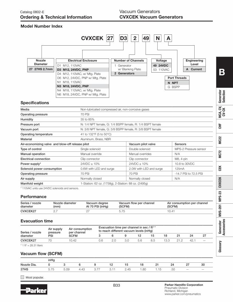
B33 Parker Hannifin CorporationPneumatic DivisionRichland, Michiganwww.parker.com/pneumatics
B
Gene
rato
r Se
lect
ion
MCA
, CV,
CV
-CK
CHF
MC2
2M
C72
CEK
CVXC
EKM
PS-2
3M
VS-2
01Ge
nera
tor
Acce
ssor
ies
Glos
sary
Catalog 0802-E
Ordering & Technical InformationVacuum GeneratorsCVXCEK Vacuum Generators
Specifications
Media Non-lubricated compressed air, non-corrosive gases
Operating pressure 70 PSI
Humidity 35 to 85%
Pressure port N: 1/4 NPT female, G: 1/4 BSPP female, R: 1/4 BSPT female
Vacuum port N: 3/8 NPT female, G: 3/8 BSPP female, R: 3/8 BSPT female
Operating temperature 41 to 132°F (5 to 50°C)
Material Aluminum, Brass, NBR
Air-economizing valve and blow-off release pilot Vacuum pilot valve Sensors
Type of control Single solenoid Double solenoid MPS-2 Pressure sensor
Manual operation Manual override Manual overrides N/A
Electrical connection Clip connector Clip connector M8, 4-pin
Power supply* 24VDC ± 10% 24VDC ± 10% 10.8 to 30VDC
Solenoid power consumption 0.6W with LED and surge 2.0W with LED and surge 125mA
Operating pressure 70 PSI 70 PSI -14.7 PSI to 72.5 PSI
Air supply Normally closed Normally closed N/A
Manifold weight 1-Station: 62 oz. (1758g), 2-Station: 88 oz. (2495g)
* 110VAC units use 24VDC solenoids and sensors.
PerformanceSeries / nozzle diameter
Nozzle diameter(mm)
Vacuum degreeAt 70 PSI (inHg)
Vacuum flow per channel(SCFM)
Air consumption per channel(SCFM)
CVXCEK27 2.7 27 5.75 10.41
Vacuum flow (SCFM)inHg
Nozzle Dia. 0 3 6 9 12 15 18 21 24 27 30
27HS 5.75 5.09 4.43 3.77 3.11 2.45 1.80 1.15 .50 — —
Evacuation time
Series / nozzle diameter
Air supplypressurePSI
Air consumptionper channelSCFM
Evacuation time per channel in sec / ft3 *to reach different vacuum levels (inHg)
3 6 9 12 15 18 21 24 27
CVXCEK27 70 10.42 0.6 2.0 3.0 5.6 8.5 13.3 21.2 42.1 —
* 1 ft3 = 28.31 liters
Electrical Enclosure
D1 M12, 110VAC D3 M12, 24VDC, PNP D4 M12, 110VAC, w/ Mtg. Plate D6 M12, 24VDC, PNP w/ Mtg. Plate N1 M18, 110VAC N3 M18, 24VDC, PNP N4 M18, 110VAC, w/ Mtg. Plate N6 M18, 24VDC, PNP w/ Mtg. Plate
Engineering Level
A Current
Nozzle Diameter
27 27HS 2.7mm
Voltage
49 24VDC 53 110VAC
Number of Channels
1 Generator w/ Blanking Plate 2 Generators
Port Threads
N NPT G BSPP
Model Number Index
Most popular.
CVXCEK 27 D3 2 49 N A
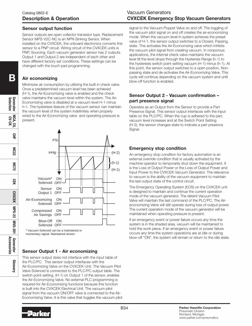
B34 Parker Hannifin CorporationPneumatic DivisionRichland, Michiganwww.parker.com/pneumatics
B
Generator Selection
MCA, CV,
CV-CKCHF
MC22
MC72
CEKCVXCEK
MPS-23
MVS-201
Generator Accessories
Glossary
Catalog 0802-E
Description & Operation
Sensor output functionSensor outputs are open collector transistor type. Replacement Sensor MPS-V2C-NC is an NPN Sinking Sensor. When installed on the CVXCEK, the onboard electronics converts this sensor to a PNP circuit. Wiring circuit of the CVXCEK units is PNP, Sourcing. Each vacuum generator sensor has 2 outputs. Output 1 and Output 2 are independent of each other and have different factory set conditions. These settings can be changed with the touch pad programming.
Air economizingMinimizes air consumption by utilizing the built in check valve. Once a predetermined vacuum level has been achieved (H-1), the Air-Economizing valve is enabled and the check valve maintains the vacuum level within the system. The Air-Economizing valve is disabled at a vacuum level H-1 minus h-1. The hysteresis feature of the vacuum sensor can maintain the vacuum level of the system indefinitely when properly wired to the Air-Economizing valve and operating pressure is present.
Sensor Output 1 - Air economizingThis sensor output does not interface with the input table of the PLC/PC. This sensor output interfaces with the Air-Economizing Valve on the CVXCEK Unit. The Vacuum Pilot Valve Solenoid is connected to the PLC/PC output table. The switch point setting, (H-1) on Output 1 of the sensor, enables the Air-Economizing Valve. No external PLC programming is required for Air-Economizing functions because this function is built into the CVXCEK Electrical Unit. The vacuum pilot signal from the vacuum ON/OFF valve is connected to the Air-Economizing Valve. It is this valve that toggles the vacuum pilot
signal to the Vacuum Poppet Valve on and off. The toggling of the vacuum pilot signal on and off creates the air-economizing mode. When the vacuum level in system achieves the preset valve of H-1, the sensor output switches to a Closed, Passing, state. This activates the Air-Economzing valve which inhibits the vacuum pilot signal from creating vacuum. In nonporous applications, the internal check valve maintains the vacuum level till the level drops through the Hysterisis Range (h-1) to the hysteresis switch point setting vacuum (H-1) minus (h-1). At this point, the sensor output switches to a open position, Non-passing state and de-activates the Air-Economzing Valve. This cycle will continue depending on the vacuum system and until blow-off function is enabled.
Sensor Output 2 - Vacuum confirmation – part presence signalOperates as an Output from the Sensor to provide a Part Presence Signal. This sensor output interfaces with the Input table on the PLC/PC. When the cup is adhered to the part, vacuum level increases and at the Switch Point Setting (H-2), the sensor changes state to indicate a part presence Signal.
PSI
inHg
ONOFF
ONOFF
Vacuum*Solenoid
Sensor Output 1
ONOFF
ONOFF
Blow-OffSolenoid
CompressedAir Savings
(h-1)
(H-1)
(H-2)
ONOFF
Air-Economizing Solenoid
* Vacuum Solenoid can be a maintained or momentary signal. Maintained shown.
Emergency stop conditionAn emergency stop condition for factory automation is an external override condition that is usually activated by the machine operator to temporarily shut down the equipment. It is the Loss of Output Power or the Loss of Output Power and Input Power to the CVXCEK Vacuum Generator. The relevance to vacuum is the ability of the vacuum equipment to maintain the last output state of the control circuit.
The Emergency Operating System (EOS) on the CVXCEK unit is designed to maintain and continue the current operation mode of the vacuum generator. The detent Vacuum Pilot Valve will maintain the last command of the PLC/PC. The Air-economizing Valve will still operate during loss of output power. The current operation mode of the vacuum generator will be maintained when operating pressure is present.
If an emergency event or power failure occurs any time the system is in the shaded area, vacuum will be maintained to hold the work piece. If an emergency event or power failure occurs any time the system operations are at idle or during blow-off “ON”, the system will remain or return to the idle state.
Vacuum GeneratorsCVXCEK Emergency Stop Vacuum Generators
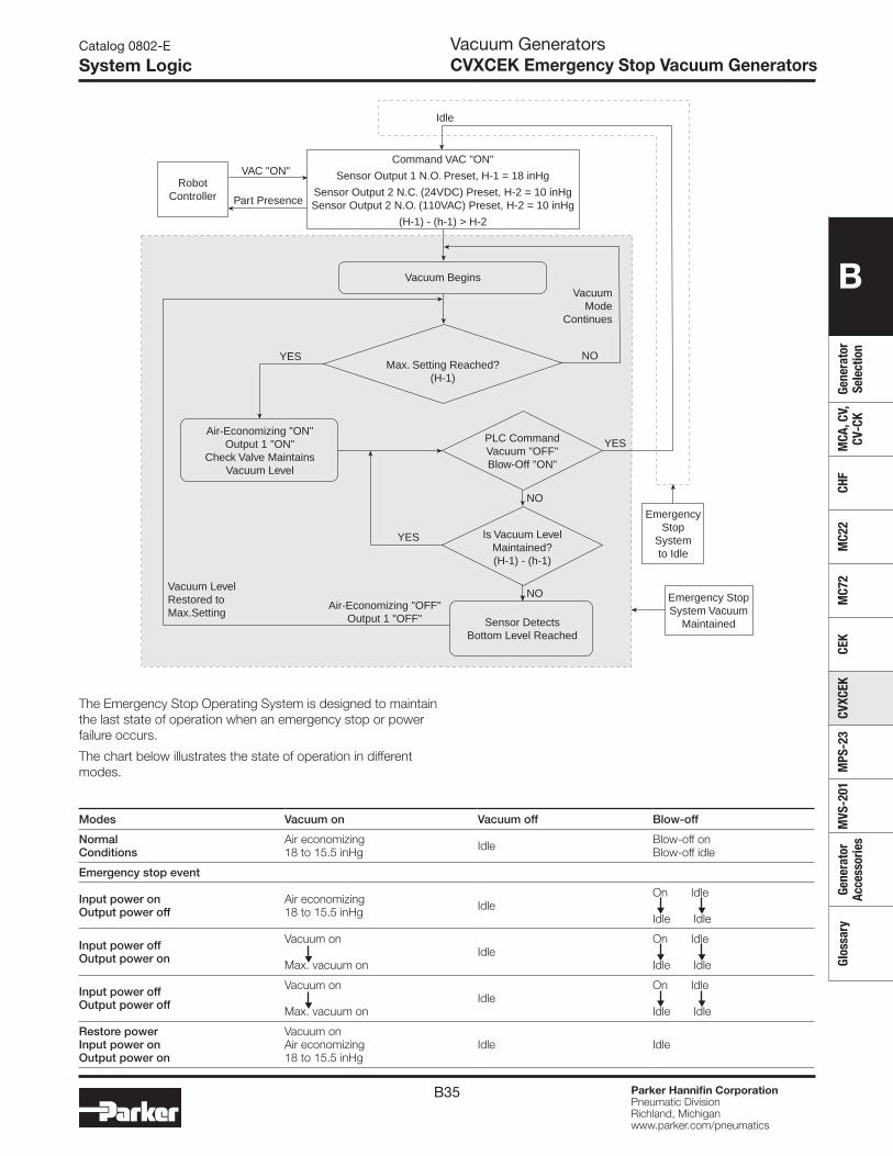
B35 Parker Hannifin CorporationPneumatic DivisionRichland, Michiganwww.parker.com/pneumatics
B
Gene
rato
r Se
lect
ion
MCA
, CV,
CV
-CK
CHF
MC2
2M
C72
CEK
CVXC
EKM
PS-2
3M
VS-2
01Ge
nera
tor
Acce
ssor
ies
Glos
sary
Catalog 0802-E
System Logic
Idle
YES NO
NO
NO
YES
YES
Max. Setting Reached? (H-1)
PLC CommandVacuum "OFF"Blow-Off "ON"
Emergency Stop
Systemto Idle
Emergency StopSystem Vacuum
Maintained
Is Vacuum LevelMaintained?(H-1) - (h-1)
Sensor DetectsBottom Level Reached
Air-Economizing "ON"Output 1 "ON"
Check Valve MaintainsVacuum Level
Vacuum LevelRestored toMax.Setting
Air-Economizing "OFF"Output 1 "OFF"
VAC "ON"
Vacuum BeginsVacuum
ModeContinues
Part Presence
Command VAC "ON"
Sensor Output 1 N.O. Preset, H-1 = 18 inHg
Sensor Output 2 N.C. (24VDC) Preset, H-2 = 10 inHgSensor Output 2 N.O. (110VAC) Preset, H-2 = 10 inHg
(H-1) - (h-1) > H-2
RobotController
The Emergency Stop Operating System is designed to maintain the last state of operation when an emergency stop or power failure occurs.
The chart below illustrates the state of operation in different modes.
Modes Vacuum on Vacuum off Blow-off
NormalConditions
Air economizing18 to 15.5 inHg Idle Blow-off on
Blow-off idle
Emergency stop event
Input power onOutput power off
Air economizing18 to 15.5 inHg Idle
On Idle Idle Idle
Input power offOutput power on
Vacuum on
Max. vacuum onIdle
On Idle Idle Idle
Input power offOutput power off
Vacuum on
Max. vacuum onIdle
On Idle Idle Idle
Restore powerInput power onOutput power on
Vacuum onAir economizing18 to 15.5 inHg
Idle Idle
Vacuum GeneratorsCVXCEK Emergency Stop Vacuum Generators
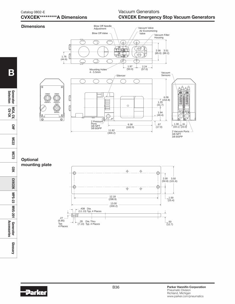
B36 Parker Hannifin CorporationPneumatic DivisionRichland, Michiganwww.parker.com/pneumatics
B
Generator Selection
MCA, CV,
CV-CKCHF
MC22
MC72
CEKCVXCEK
MPS-23
MVS-201
Generator Accessories
Glossary
Catalog 0802-E
CVXCEK*********A DimensionsVacuum GeneratorsCVXCEK Emergency Stop Vacuum Generators
2.56(65.0)
3.51(89.2)
1.76(44.6)
2.24(57.0)
1.97(50.0)
Blow Off Valve
Mounting Holes4 - 5.5mm
Blow Off NeedleAdjustment Vacuum Valve
Air EconomizingValve
Vacuum FilterHousing
.67(17.0)
1.25(31.7)
11.82(300.2)
6.38(162.0)
Silencer
1.94(49.4)
.91 (23.0)
1.30(33.1)
6.09(154.8)
VacuumSensors
2 Vacuum Ports3/8 NPT3/8 BSPP
2 PressurePorts3/8 NPT3/8 BSPP
Output
Channel 1Input
Sensors
Output
Channel 2
12 M
OD
E12 M
OD
E
13.00(330.2)
3.50(101.6)
12.18(298.9)
2.00(50.8)
.50(12.7)
1.00(25.4)
.28(7.13)
Dia. ThruTyp. 4 Places
.27(6.85)Typ.4 Places
.438(11.13)
Dia.Typ. 4 Places
Optional mounting plate
Dimensions
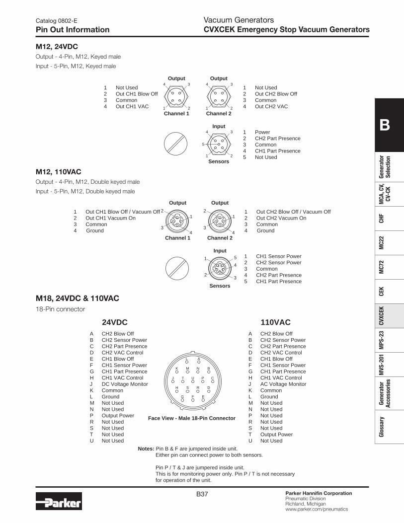
B37 Parker Hannifin CorporationPneumatic DivisionRichland, Michiganwww.parker.com/pneumatics
B
Gene
rato
r Se
lect
ion
MCA
, CV,
CV
-CK
CHF
MC2
2M
C72
CEK
CVXC
EKM
PS-2
3M
VS-2
01Ge
nera
tor
Acce
ssor
ies
Glos
sary
Catalog 0802-E
Pin Out InformationVacuum GeneratorsCVXCEK Emergency Stop Vacuum Generators
A CH2 Blow Off B CH2 Sensor Power C CH2 Part Presence D CH2 VAC Control E CH1 Blow Off F CH1 Sensor Power G CH1 Part Presence H CH1 VAC Control J DC Voltage Monitor K Common L Ground M Not UsedN Not UsedP Output PowerR Not UsedS Not UsedT Not UsedU Not Used
24VDC
J
K M N B
H S R D
EG F
L A
T U P C
A CH2 Blow Off B CH2 Sensor Power C CH2 Part Presence D CH2 VAC Control E CH1 Blow Off F CH1 Sensor Power G CH1 Part Presence H CH1 VAC Control J AC Voltage Monitor K Common L Ground M Not UsedN Not UsedP Not UsedR Not UsedS Not UsedT Output PowerU Not Used
110VAC
Face View - Male 18-Pin Connector
Notes: Pin B & F are jumpered inside unit. Either pin can connect power to both sensors.
Pin P / T & J are jumpered inside unit. This is for monitoring power only. Pin P / T is not necessary for operation of the unit.
2
4 3Output
Channel 1
1 2
4
5
3Input
Sensors
2
4 3Output
Channel 21 1
1 Power2 CH2 Part Presence3 Common4 CH1 Part Presence5 Not Used
1 Not Used2 Out CH2 Blow Off3 Common4 Out CH2 VAC
1 Not Used2 Out CH1 Blow Off3 Common4 Out CH1 VAC
M12, 24VDCOutput - 4-Pin, M12, Keyed male
Input - 5-Pin, M12, Keyed male
M18, 24VDC & 110VAC18-Pin connector
1 CH1 Sensor Power2 CH2 Sensor Power3 Common4 CH2 Part Presence5 CH1 Part Presence
1 Out CH1 Blow Off / Vacuum Off2 Out CH1 Vacuum On3 Common4 Ground
1 Out CH2 Blow Off / Vacuum Off2 Out CH2 Vacuum On3 Common4 Ground
Output
Channel 1
Input
Sensors
Output
Channel 24
1
3
2
4
3
5
2
1
4
1
3
2
M12, 110VACOutput - 4-Pin, M12, Double keyed male
Input - 5-Pin, M12, Double keyed male
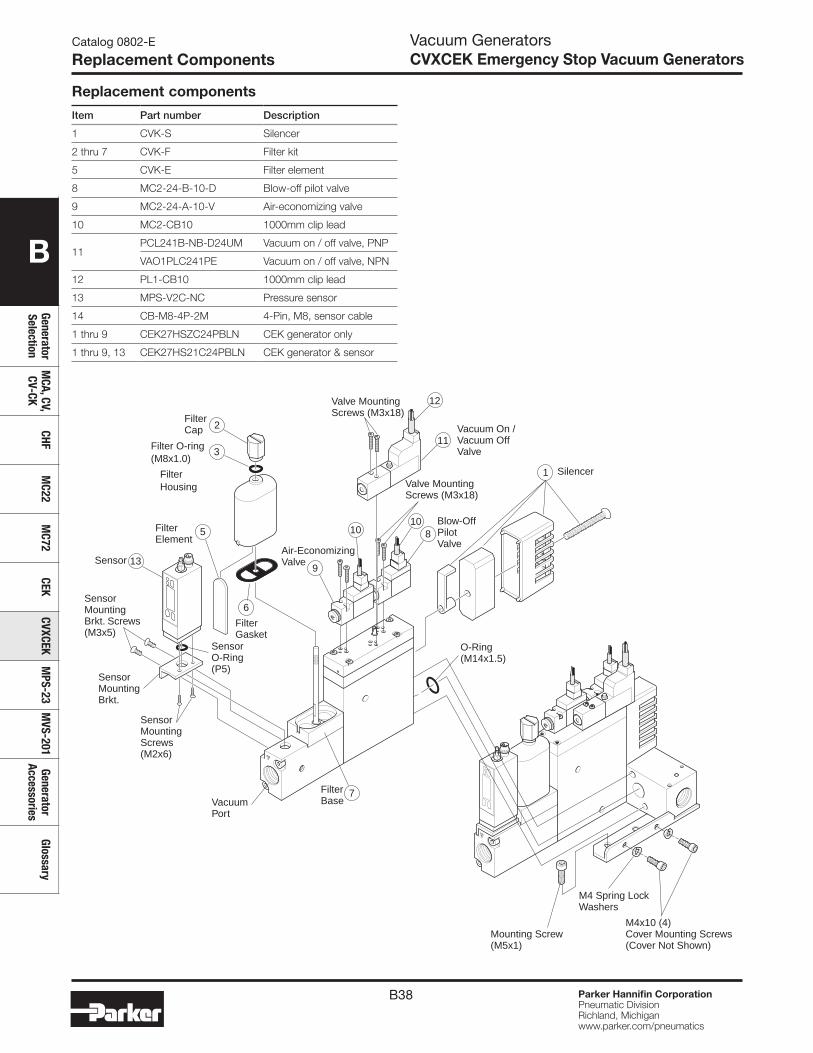
B38 Parker Hannifin CorporationPneumatic DivisionRichland, Michiganwww.parker.com/pneumatics
B
Generator Selection
MCA, CV,
CV-CKCHF
MC22
MC72
CEKCVXCEK
MPS-23
MVS-201
Generator Accessories
Glossary
Catalog 0802-E
Replacement Components
Mounting Screw(M5x1)
M4x10 (4)Cover Mounting Screws(Cover Not Shown)
M4 Spring LockWashers
O-Ring(M14x1.5)
Sensor
SensorO-Ring(P5)
SensorMountingBrkt.
SensorMountingBrkt. Screws(M3x5)
SensorMountingScrews(M2x6)
VacuumPort
FilterBase
FilterElement
FilterGasket
5
6
7
3
FilterCap
Filter O-ring(M8x1.0)
13
FilterHousing
2
Valve MountingScrews (M3x18)
1 Silencer
Blow-OffPilotValve
Vacuum On /Vacuum OffValve
810
10
Air-EconomizingValve
9
11
12
Valve MountingScrews (M3x18)
Replacement components
Item Part number Description
1 CVK-S Silencer
2 thru 7 CVK-F Filter kit
5 CVK-E Filter element
8 MC2-24-B-10-D Blow-off pilot valve
9 MC2-24-A-10-V Air-economizing valve
10 MC2-CB10 1000mm clip lead
11PCL241B-NB-D24UM Vacuum on / off valve, PNP
VAO1PLC241PE Vacuum on / off valve, NPN
12 PL1-CB10 1000mm clip lead
13 MPS-V2C-NC Pressure sensor
14 CB-M8-4P-2M 4-Pin, M8, sensor cable
1 thru 9 CEK27HSZC24PBLN CEK generator only
1 thru 9, 13 CEK27HS21C24PBLN CEK generator & sensor
Vacuum GeneratorsCVXCEK Emergency Stop Vacuum Generators
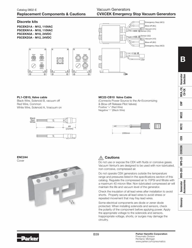
B39 Parker Hannifin CorporationPneumatic DivisionRichland, Michiganwww.parker.com/pneumatics
B
Gene
rato
r Se
lect
ion
MCA
, CV,
CV
-CK
CHF
MC2
2M
C72
CEK
CVXC
EKM
PS-2
3M
VS-2
01Ge
nera
tor
Acce
ssor
ies
Glos
sary
CautionsDo not use or expose the CEK with fluids or corrosive gases. Vacuum Venturi’s are designed to be used with non-lubricated, non-corrosive, compressed air.
Do not operate CEK generators outside the temperature range and pressures listed in the specifications section of this catalog. Regulate the compressed air to 70PSI and filtrate with a maximum 40 micron filter. Non-lubricated compressed air will maintain the life and vacuum level of the generator.
Check the insulation of all lead wires after installation to avoid shorts. Properly secure all lead wires to avoid stress or repeated movement that may fray lead wires.
Some electrical components are diode or zener diode protected. When installing solenoids and sensors, check the polarity of the component before applying power. Apply the appropriate voltage to the solenoids and sensors. Inappropriate voltage, shorts, or surges may damage the circuitry.
!
1000mm
BlackRed
White
.83 (21mm)
MC22-CB10 Valve Cable(Connects Power Source to the Air-Economizing & Blow-off Release Pilot Valves)Positive “+” (Red Wire)Negative “-” (Black Wire)
1000mm
PL1-CB10, Valve cableBlack Wire, Solenoid B, vacuum offRed Wire, CommonWhite Wire, Solenoid A, Vvacuum on
Sensor (S2)
Blow-off (B2)
Emergency Stop (AE2)
Vacuum (V2)
Output
Channel 1Input
Sensors
Output
Channel 2
Sensor (S1)
Blow-off (B1)
Emergency Stop (AE1)
Vacuum (V1)
J
K M N B
H S R D
EGF
L A
T U P C
Output
Channel 1
Input
Sensors
Output
Channel 2
Discrete kitsPSCEKD1A - M12, 110VACPSCEKN1A - M18, 110VACPSCEKN3A - M18, 24VDCPSCEKD3A - M12, 24VDC
Catalog 0802-E
Replacement Components & Cautions
ENC244Cover
Vacuum GeneratorsCVXCEK Emergency Stop Vacuum Generators

B40
B
Generator Selection
MCA, CV,
CV-CKCHF
MC22
MC72
CEKCVXCEK
MPS-23
MVS-201
Generator Accessories
Glossary
Parker Hannifin CorporationPneumatic DivisionRichland, Michiganwww.parker.com/pneumatics
Catalog 0802-E
Features, Ordering InformationPressure SensorsMPS-23 1-Color Generator Mount
Features• Pressure range:
Vacuum pressure: 0 to -30 inHg
• Sensor output: 2 NPN or PNP open collector Transistor output, 30VDC, 125mA
• Switch Point and Window Comparator Mode
• Selectable units of measure
• Output response time less than 2.0 milliseconds
• RoHS
• Air and non-corrosive gases
• Error message
MPS-23 sensor only ordering numbers
Pressure range Port thread Electrical output Electrical connection Part number
0-30 inHg Ejector mount (2) PNP M8 on 1M cable, 4-Pin MPS-V23C-PC
0-30 inHg Ejector mount (2) NPN M8 on 1M cable, 4-Pin MPS-V23C-NC
Sw
itch
mai
n ci
rcui
t
Sw
itch
mai
n ci
rcui
t
0V (Blue)
DC 12~24V± 10%
Out 1 (Black)
Out 2 (White)
Load
Load
+V (Brown)
0V (Blue)
Out 1 (Black)
Out 2 (White)
+V (Brown)
NPN Output PNP Output
+
−DC 12~24V
± 10%
+
−
Max.80mA
Load
Load
Max.80mA
Max.80mA
Max.80mA
Internal circuit for open collector and analog output wiring
MPS-23 Accessories
M8, 4-Pin, 2 meter cable CB-M8-4P-2M-PUR
M8, 4-Pin, 5 meter cable CB-M8-4P-5M-PUR
Sensor pin outPin # 1 Brown: 24VDC 2 White: PNP/NPN Open Collector Output 2 3 Blue: 0VDC 4 Black: PNP/NPN Open Collector Output 1
2
1
4
3
Programming optionsOutputs change N.O. / N.C. 4
Units of measure change 4
Hysteresis mode 4
Window comparator mode 4
Auto teach mode 4
Output response time 4Lockout option —Password lockout 4
Max. value display 4
Min. value display 4
Zero reset 4
Error output mode 4
Most popular.
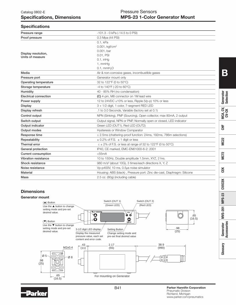
B41
B
Gene
rato
r Se
lect
ion
MCA
, CV,
CV
-CK
CHF
MC2
2M
C72
CEK
CVXC
EKM
PS-2
3M
VS-2
01Ge
nera
tor
Acce
ssor
ies
Glos
sary
Parker Hannifin CorporationPneumatic DivisionRichland, Michiganwww.parker.com/pneumatics
Catalog 0802-E
Specifications, DimensionsPressure SensorsMPS-23 1-Color Generator Mount
SpecificationsPressure range -101.3 - 0 kPa (-14.5 to 0 PSI)
Proof pressure 0.3 Mpa (44 PSI)
Display resolution, Units of measure
0.1, kPa0.001, kgf/cm2
0.001, bar0.01, PSI0.1, inHg1, mmHg0.1, mmH2O
Media Air & non-corrosive gases, incombustible gases
Pressure port Generator mount only
Operating temperature 32 to 122°F (0 to 50°C)
Storage temperature -4 to 140°F (-20 to 60°C)
Humidity 40 - 85% RH (no condensation)
Electrical connection (C) 4-pin, M8 connector on 1M lead wire
Power supply 12 to 24VDC ±10% or less, Ripple (Vp-p) 10% or less
Display 3 + 1/2 digit, 1 color, 7-segment RED LED
Display refresh .1 to 3.0 Seconds, Variable (factory set at 0.1)
Control output NPN (Sinking), PNP (Sourcing), Open collector, max 80mA, 2 output
Switch output Output signal, NPN or PNP, Normally open or closed, LED indicator
Output indicator Green LED (OUT1), Red LED (OUT2)
Output modes Hysteresis or Window Comparator
Response time ≤ 2.5ms (chattering-proof function: 24ms, 192ms, 786m selections)
Repeatability ± 0.2% of F.S. ± 1 digit or less
Thermal error ≤ ± 2% of F.S. or less at range of 32 to 122°F (0 to 50°C)
General protection IP40, CE marked, EMC-EN61000-6-2: 2001
Current consumption <55mA
Vibration resistance 10 to 150Hz, Double amplitude 1.5mm, XYZ, 2 hrs.
Shock resistance 980 m/s² (about 10G), 3 times/each directions X, Y, Z
Noise resistance Vp-p400V, 10 ms, 0.5μs noise simulator
Material Housing: ABS (black) , Pressure port: Zinc die-cast, Diaphragm: Silicone
Mass 2.5 oz. (80g) (including cable)
DimensionsGenerator mount
.65(16.5)
.65(16.5)
.98(25)
.98(25)
2.17(55)
.43(11)
For mounting on Generator
Ø 8Ø 5
M2x0.4
kPa
MODE
38.9(990)
Switch (OUT 1)
(Green LED)
Switch (OUT 2)
Setting Button
Change setting mode andpre-set final desired value
3-1/2 digit LED display
Display the measuredpressure value, each setcontent and error code.
(Red LED)
() Button
Use the button to changesetting mode and pre-setdesired value.
() Button
Use the button to changesetting mode and pre-setdesired value.
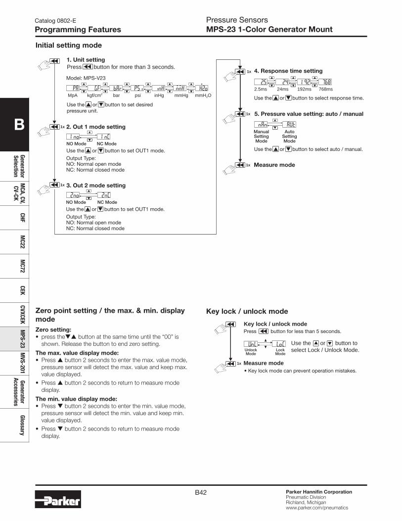
B42
B
Generator Selection
MCA, CV,
CV-CKCHF
MC22
MC72
CEKCVXCEK
MPS-23
MVS-201
Generator Accessories
Glossary
Parker Hannifin CorporationPneumatic DivisionRichland, Michiganwww.parker.com/pneumatics
Catalog 0802-E
Programming Features
4. Response time setting
5. Pressure value setting: auto / manual
Measure modeOutput Type: NO: Normal open modeNC: Normal closed mode
Model: MPS-V23
Use the or button to set desiredpressure unit.
Use the or button to select response time.
Use the or button to select auto / manual. Use the or button to set OUT1 mode.
Output Type: NO: Normal open modeNC: Normal closed mode
Use the or button to set OUT1 mode.
NC ModeNO Mode
MpA bar psi inHg mmHg mmH2Okgf/cm2
2.5ms 192ms 768ms24ms
3. Out 2 mode setting
2. Out 1 mode setting
NC ModeNO Mode
ManualSettingMode
AutoSettingMode
1. Unit setting
1x
1x
1x
1x
1x
Press button for more than 3 seconds.
UnlockMode
LockMode
Measure mode• Key lock mode can prevent operation mistakes.
Press button for less than 5 seconds.Key lock / unlock mode
Use the or button toselect Lock / Unlock Mode.
1x
Key lock / unlock mode
Initial setting mode
Pressure SensorsMPS-23 1-Color Generator Mount
Zero point setting / the max. & min. display mode Zero setting:• press the button at the same time until the “00” is
shown. Release the button to end zero setting.
The max. value display mode:• Press button 2 seconds to enter the max. value mode,
pressure sensor will detect the max. value and keep max. value displayed.
• Press button 2 seconds to return to measure mode display.
The min. value display mode:• Press button 2 seconds to enter the min. value mode,
pressure sensor will detect the min. value and keep min. value displayed.
• Press button 2 seconds to return to measure mode display.
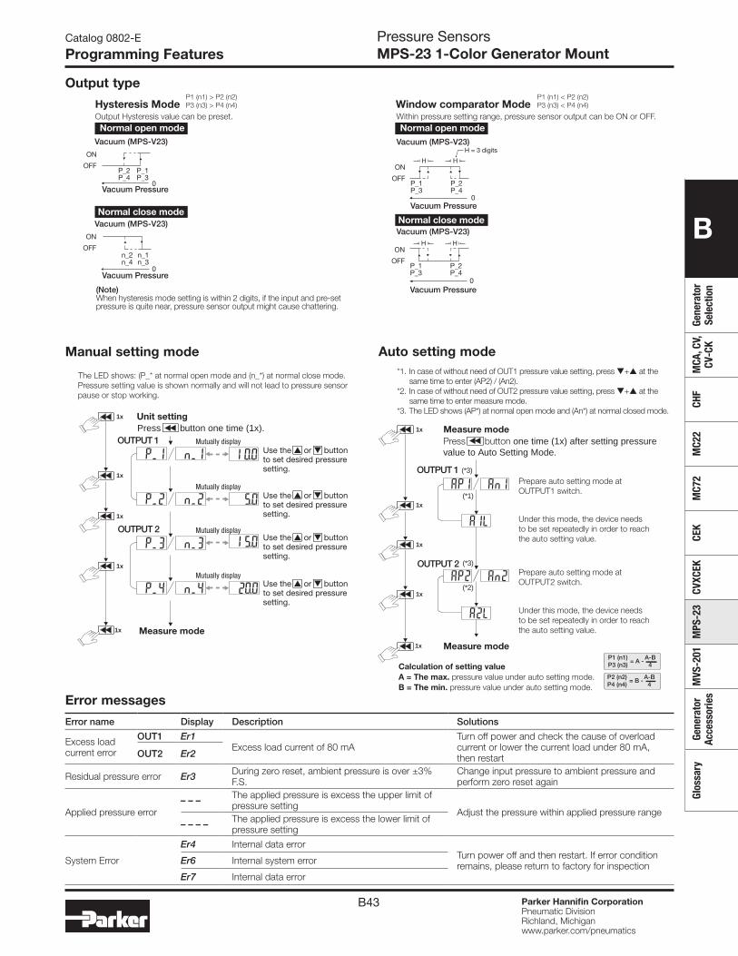
B43
B
Gene
rato
r Se
lect
ion
MCA
, CV,
CV
-CK
CHF
MC2
2M
C72
CEK
CVXC
EKM
PS-2
3M
VS-2
01Ge
nera
tor
Acce
ssor
ies
Glos
sary
Parker Hannifin CorporationPneumatic DivisionRichland, Michiganwww.parker.com/pneumatics
Catalog 0802-E
Programming Features
Hysteresis ModeOutput Hysteresis value can be preset. Within pressure setting range, pressure sensor output can be ON or OFF.
Vacuum (MPS-V23)
Vacuum (MPS-V23)
Vacuum (MPS-V23)
Vacuum (MPS-V23)
Vacuum Pressure
Vacuum Pressure
Vacuum Pressure
Vacuum Pressure
P1 (n1) > P2 (n2)P3 (n3) > P4 (n4) Window comparator Mode
P1 (n1) < P2 (n2)P3 (n3) < P4 (n4)
Normal open mode
Normal close mode
Normal open mode
Normal close mode
P_2P_4
0
0
0
0
P_1P_3
ON
OFFn_2n_4
n_1n_3
ON
OFF
(Note)When hysteresis mode setting is within 2 digits, if the input and pre-setpressure is quite near, pressure sensor output might cause chattering.
P_2P_4
P_1P_3
ON
OFF
H H
P_2P_4
P_1P_3
ON
OFF
H H
H = 3 digits
Error messages
Error name Display Description Solutions
Excess load current error
OUT1 Er1Excess load current of 80 mA
Turn off power and check the cause of overload current or lower the current load under 80 mA, then restart OUT2 Er2
Residual pressure error Er3 During zero reset, ambient pressure is over ±3% F.S.
Change input pressure to ambient pressure and perform zero reset again
Applied pressure error– – – The applied pressure is excess the upper limit of
pressure settingAdjust the pressure within applied pressure range
– – – – The applied pressure is excess the lower limit of pressure setting
System Error
Er4 Internal data errorTurn power off and then restart. If error condition remains, please return to factory for inspectionEr6 Internal system error
Er7 Internal data error
Output type
Manual setting mode Auto setting mode
Mutually displayOUTPUT 1
OUTPUT 2
Measure mode
The LED shows: (P_* at normal open mode and (n_*) at normal close mode.Pressure setting value is shown normally and will not lead to pressure sensorpause or stop working.
Use the or buttonto set desired pressuresetting.
Use the or buttonto set desired pressuresetting.
Use the or buttonto set desired pressuresetting.
Use the or buttonto set desired pressuresetting.
Press button one time (1x).
1x
1x
1x
1x
1x
Mutually display
Mutually display
Mutually display
Unit setting
*1. In case of without need of OUT1 pressure value setting, press + at thesame time to enter (AP2) / (An2).
*2. In case of without need of OUT2 pressure value setting, press + at thesame time to enter measure mode.
*3. The LED shows (AP*) at normal open mode and (An*) at normal closed mode.
(*1)
(*3)
(*2)
(*3)
Prepare auto setting mode atOUTPUT1 switch.
Under this mode, the device needsto be set repeatedly in order to reachthe auto setting value.
Under this mode, the device needsto be set repeatedly in order to reachthe auto setting value.
Prepare auto setting mode atOUTPUT2 switch.
P2 (n2)P4 (n4)
A-B4
= B -
P1 (n1)P3 (n3)
A-B4
= A -Calculation of setting valueA = The max. pressure value under auto setting mode.B = The min. pressure value under auto setting mode.
Measure mode
Measure mode
Press button one time (1x) after setting pressurevalue to Auto Setting Mode.
OUTPUT 1
OUTPUT 2
1x
1x
1x
1x
1x
Pressure SensorsMPS-23 1-Color Generator Mount
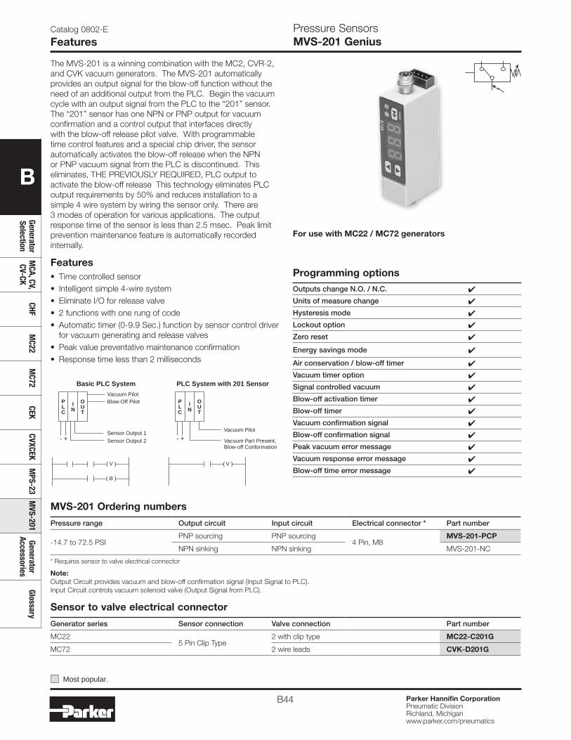
B44 Parker Hannifin CorporationPneumatic DivisionRichland, Michiganwww.parker.com/pneumatics
B
Generator Selection
MCA, CV,
CV-CKCHF
MC22
MC72
CEKCVXCEK
MPS-23
MVS-201
Generator Accessories
Glossary
Note:Output Circuit provides vacuum and blow-off confirmation signal (Input Signal to PLC). Input Circuit controls vacuum solenoid valve (Output Signal from PLC).
Most popular.
Basic PLC System PLC System with 201 Sensor
PLC
IN
OUT
- +
Vacuum PilotBlow-Off Pilot
Sensor Output 2Sensor Output 1
( V )
( B )
PLC
IN
OUT
- +Vacuum Pilot
Vacuum Part Present,Blow-off Conformation
( V )
Pressure SensorsMVS-201 Genius
Catalog 0802-E
Features
Features• Time controlled sensor• Intelligent simple 4-wire system• Eliminate I/O for release valve• 2 functions with one rung of code• Automatic timer (0-9.9 Sec.) function by sensor control driver
for vacuum generating and release valves• Peak value preventative maintenance confirmation• Response time less than 2 milliseconds
For use with MC22 / MC72 generators
The MVS-201 is a winning combination with the MC2, CVR-2, and CVK vacuum generators. The MVS-201 automatically provides an output signal for the blow-off function without the need of an additional output from the PLC. Begin the vacuum cycle with an output signal from the PLC to the “201” sensor. The “201” sensor has one NPN or PNP output for vacuum confirmation and a control output that interfaces directly with the blow-off release pilot valve. With programmable time control features and a special chip driver, the sensor automatically activates the blow-off release when the NPN or PNP vacuum signal from the PLC is discontinued. This eliminates, THE PREVIOUSLY REQUIRED, PLC output to activate the blow-off release This technology eliminates PLC output requirements by 50% and reduces installation to a simple 4 wire system by wiring the sensor only. There are 3 modes of operation for various applications. The output response time of the sensor is less than 2.5 msec. Peak limit prevention maintenance feature is automatically recorded internally.
Programming optionsOutputs change N.O. / N.C. 4
Units of measure change 4
Hysteresis mode 4
Lockout option 4
Zero reset 4
Energy savings mode 4
Air conservation / blow-off timer 4
Vacuum timer option 4
Signal controlled vacuum 4
Blow-off activation timer 4
Blow-off timer 4
Vacuum confirmation signal 4
Blow-off confirmation signal 4
Peak vacuum error message 4
Vacuum response error message 4
Blow-off time error message 4
MVS-201 Ordering numbers
Pressure range Output circuit Input circuit Electrical connector * Part number
-14.7 to 72.5 PSIPNP sourcing PNP sourcing
4 Pin, M8MVS-201-PCP
NPN sinking NPN sinking MVS-201-NC
* Requires sensor to valve electrical connector
Sensor to valve electrical connector
Generator series Sensor connection Valve connection Part number
MC225 Pin Clip Type
2 with clip type MC22-C201G
MC72 2 wire leads CVK-D201G
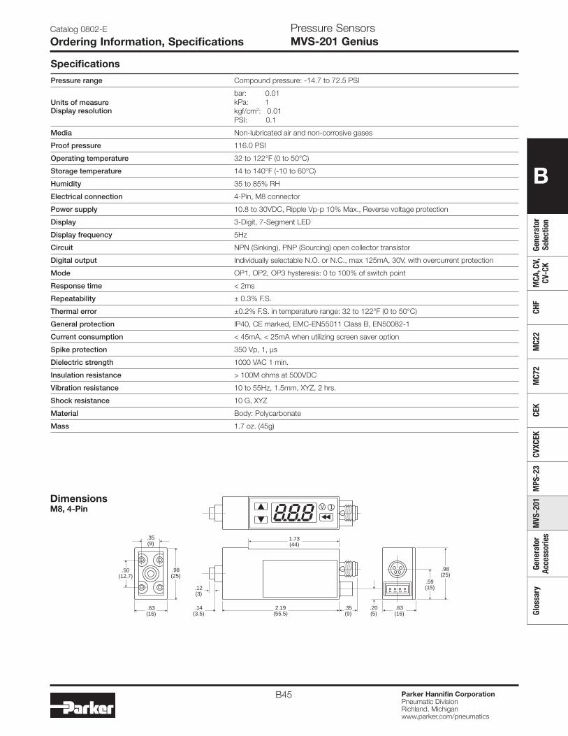
B45 Parker Hannifin CorporationPneumatic DivisionRichland, Michiganwww.parker.com/pneumatics
B
Gene
rato
r Se
lect
ion
MCA
, CV,
CV
-CK
CHF
MC2
2M
C72
CEK
CVXC
EKM
PS-2
3M
VS-2
01Ge
nera
tor
Acce
ssor
ies
Glos
sary
Catalog 0802-E
Ordering Information, SpecificationsPressure SensorsMVS-201 Genius
Specifications
Pressure range Compound pressure: -14.7 to 72.5 PSI
Units of measureDisplay resolution
bar: 0.01kPa: 1kgf/cm2: 0.01PSI: 0.1
Media Non-lubricated air and non-corrosive gases
Proof pressure 116.0 PSI
Operating temperature 32 to 122°F (0 to 50°C)
Storage temperature 14 to 140°F (-10 to 60°C)
Humidity 35 to 85% RH
Electrical connection 4-Pin, M8 connector
Power supply 10.8 to 30VDC, Ripple Vp-p 10% Max., Reverse voltage protection
Display 3-Digit, 7-Segment LED
Display frequency 5Hz
Circuit NPN (Sinking), PNP (Sourcing) open collector transistor
Digital output Individually selectable N.O. or N.C., max 125mA, 30V, with overcurrent protection
Mode OP1, OP2, OP3 hysteresis: 0 to 100% of switch point
Response time < 2ms
Repeatability ± 0.3% F.S.
Thermal error ±0.2% F.S. in temperature range: 32 to 122°F (0 to 50°C)
General protection IP40, CE marked, EMC-EN55011 Class B, EN50082-1
Current consumption < 45mA, < 25mA when utilizing screen saver option
Spike protection 350 Vp, 1, µs
Dielectric strength 1000 VAC 1 min.
Insulation resistance > 100M ohms at 500VDC
Vibration resistance 10 to 55Hz, 1.5mm, XYZ, 2 hrs.
Shock resistance 10 G, XYZ
Material Body: Polycarbonate
Mass 1.7 oz. (45g)
.63(16)
.14(3.5)
.35(9)
2.19(55.5)
.98 (25)
.59 (15)
1.73(44)
.12(3)
V 1
.20 (5)
.35(9)
.63(16)
.98 (25)
.50 (12.7)
1234
DimensionsM8, 4-Pin
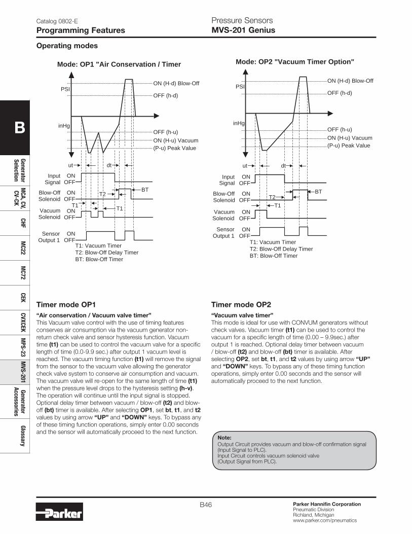
B46 Parker Hannifin CorporationPneumatic DivisionRichland, Michiganwww.parker.com/pneumatics
B
Generator Selection
MCA, CV,
CV-CKCHF
MC22
MC72
CEKCVXCEK
MPS-23
MVS-201
Generator Accessories
Glossary
Catalog 0802-E
Programming FeaturesPressure SensorsMVS-201 Genius
Operating modes
Timer mode OP1“Air conservation / Vacuum valve timer”This Vacuum valve control with the use of timing features conserves air consumption via the vacuum generator non-return check valve and sensor hysteresis function. Vacuum time (t1) can be used to control the vacuum valve for a specific length of time (0.0-9.9 sec.) after output 1 vacuum level is reached. The vacuum timing function (t1) will remove the signal from the sensor to the vacuum valve allowing the generator check valve system to conserve air consumption and vacuum. The vacuum valve will re-open for the same length of time (t1) when the pressure level drops to the hysteresis setting (h-v). The operation will continue until the input signal is stopped. Optional delay timer between vacuum / blow-off (t2) and blow-off (bt) timer is available. After selecting OP1, set bt, t1, and t2 values by using arrow “UP” and “DOWN” keys. To bypass any of these timing function operations, simply enter 0.00 seconds and the sensor will automatically proceed to the next function.
PSI
inHg
(P-u) Peak ValueON (H-u) Vacuum
OFF (h-u)
OFF (h-d)
ON (H-d) Blow-Off
InputSignal
ONOFF
ONOFF
ONOFF
ONOFF
Blow-OffSolenoid
VacuumSolenoid
Sensor Output 1
T1: Vacuum TimerT2: Blow-Off Delay TimerBT: Blow-Off Timer
Mode: OP1 "Air Conservation / Timer
T1
ut
T1
dt
T2 BT
InputSignal
ONOFF
ONOFF
ONOFF
ONOFF
Blow-OffSolenoid
VacuumSolenoid
T1: Vacuum TimerT2: Blow-Off Delay TimerBT: Blow-Off Timer
PSI
inHg
(P-u) Peak ValueON (H-u) Vacuum
OFF (h-u)
OFF (h-d)
ON (H-d) Blow-Off
BTT2
T1
Mode: OP2 "Vacuum Timer Option"
ut dt
Sensor Output 1
Timer mode OP2“Vacuum valve timer”This mode is ideal for use with CONVUM generators without check valves. Vacuum timer (t1) can be used to control the vacuum for a specific length of time (0.00 – 9.9sec.) after output 1 is reached. Optional delay timer between vacuum / blow-off (t2) and blow-off (bt) timer is available. After selecting OP2, set bt, t1, and t2 values by using arrow “UP” and “DOWN” keys. To bypass any of these timing function operations, simply enter 0.00 seconds and the sensor will automatically proceed to the next function.
Note:Output Circuit provides vacuum and blow-off confirmation signal (Input Signal to PLC). Input Circuit controls vacuum solenoid valve (Output Signal from PLC).
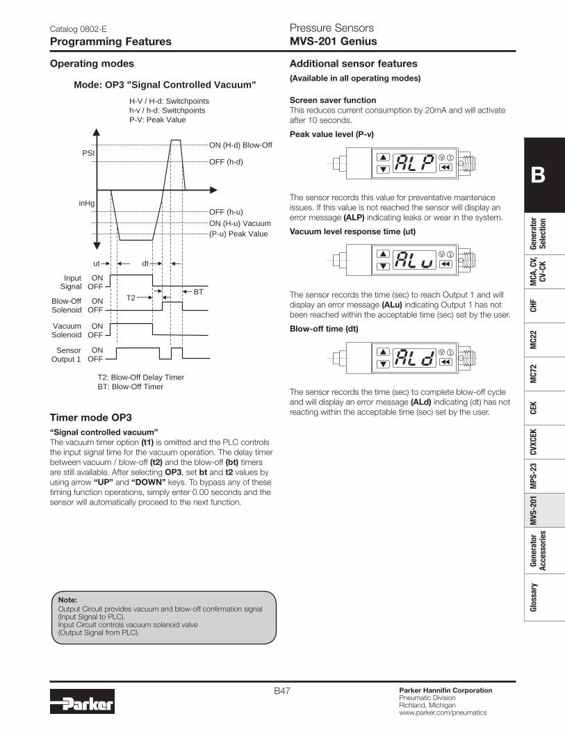
B47 Parker Hannifin CorporationPneumatic DivisionRichland, Michiganwww.parker.com/pneumatics
B
Gene
rato
r Se
lect
ion
MCA
, CV,
CV
-CK
CHF
MC2
2M
C72
CEK
CVXC
EKM
PS-2
3M
VS-2
01Ge
nera
tor
Acce
ssor
ies
Glos
sary
InputSignal
ONOFF
ONOFF
ON OFF
ONOFF
Blow-OffSolenoid
VacuumSolenoid
T2: Blow-Off Delay TimerBT: Blow-Off Timer
Mode: OP3 "Signal Controlled Vacuum"
PSI
inHg
(P-u) Peak ValueON (H-u) Vacuum
OFF (h-u)
OFF (h-d)
ON (H-d) Blow-Off
T2BT
H-V / H-d: Switchpointsh-v / h-d: SwitchpointsP-V: Peak Value
ut dt
Sensor Output 1
Timer mode OP3“Signal controlled vacuum”The vacuum timer option (t1) is omitted and the PLC controls the input signal time for the vacuum operation. The delay timer between vacuum / blow-off (t2) and the blow-off (bt) timers are still available. After selecting OP3, set bt and t2 values by using arrow “UP” and “DOWN” keys. To bypass any of these timing function operations, simply enter 0.00 seconds and the sensor will automatically proceed to the next function.
Catalog 0802-E
Programming FeaturesPressure SensorsMVS-201 Genius
Operating modes
Screen saver functionThis reduces current consumption by 20mA and will activate after 10 seconds.
Peak value level (P-v)
The sensor records this value for preventative maintenace issues. If this value is not reached the sensor will display an error message (ALP) indicating leaks or wear in the system.
Vacuum level response time (ut)
The sensor records the time (sec) to reach Output 1 and will display an error message (ALu) indicating Output 1 has not been reached within the acceptable time (sec) set by the user.
Blow-off time (dt)
The sensor records the time (sec) to complete blow-off cycle and will display an error message (ALd) indicating (dt) has not reacting within the acceptable time (sec) set by the user.
Additional sensor features(Available in all operating modes)
Note:Output Circuit provides vacuum and blow-off confirmation signal (Input Signal to PLC). Input Circuit controls vacuum solenoid valve (Output Signal from PLC).
V 1
V 1
V 1
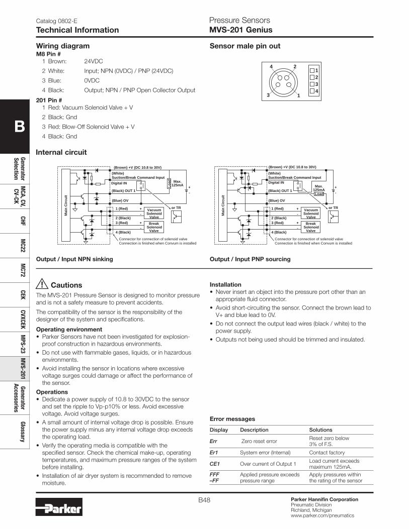
B48 Parker Hannifin CorporationPneumatic DivisionRichland, Michiganwww.parker.com/pneumatics
B
Generator Selection
MCA, CV,
CV-CKCHF
MC22
MC72
CEKCVXCEK
MPS-23
MVS-201
Generator Accessories
Glossary
Pressure SensorsMVS-201 Genius
Catalog 0802-E
Technical Information
Output / Input NPN sinking Output / Input PNP sourcing
Wiring diagram
CautionsThe MVS-201 Pressure Sensor is designed to monitor pressure and is not a safety measure to prevent accidents.
The compatibility of the sensor is the responsibility of the designer of the system and specifications.
Operating environment• Parker Sensors have not been investigated for explosion-
proof construction in hazardous environments.• Do not use with flammable gases, liquids, or in hazardous
environments.• Avoid installing the sensor in locations where excessive
voltage surges could damage or affect the performance of the sensor.
Operations• Dedicate a power supply of 10.8 to 30VDC to the sensor
and set the ripple to Vp-p10% or less. Avoid excessive voltage. Avoid voltage surges.
• A small amount of internal voltage drop is possible. Ensure the power supply minus any internal voltage drop exceeds the operating load.
• Verify the operating media is compatible with the specified sensor. Check the chemical make-up, operating temperatures, and maximum pressure ranges of the system before installing.
• Installation of air dryer system is recommended to remove moisture.
! Installation• Never insert an object into the pressure port other than an
appropriate fluid connector.• Avoid short-circuiting the sensor. Connect the brown lead to
V+ and blue lead to 0V.• Do not connect the output lead wires (black / white) to the
power supply.• Outputs not being used should be trimmed and insulated.
2
1
1234
4
3
Sensor male pin outM8 Pin #
1 Brown: 24VDC
2 White: Input; NPN (0VDC) / PNP (24VDC)
3 Blue: 0VDC
4 Black: Output; NPN / PNP Open Collector Output
201 Pin #1 Red: Vacuum Solenoid Valve + V
2 Black: Gnd
3 Red: Blow-Off Solenoid Valve + V
4 Black: Gnd
Max. 125mA
Max. 125mA
or TR or TR
Mai
n C
ircu
it
Mai
n C
ircu
it
(Brown) +V (DC 10.8 to 30V) (Brown) +V (DC 10.8 to 30V)
(Black) OUT 1
(Blue) OV
1 (Red)
2 (Black)
4 (Black)
3 (Red)
(White) Suction/Break Command Input
(Black) OUT 1
(Blue) OV
(White) Suction/Break Command Input
Digital IN Digital IN
Load
Lo
ad
VacuumSolenoid
Valve
Break Solenoid
Valve
+
-
+
-
+
-
+
-
VacuumSolenoid
Valve
Break Solenoid
Valve
+
-
+
-
Connector for connection of solenoid valveConnection is finished when Convum is installed
1 (Red)
2 (Black)
4 (Black)
3 (Red)
Connector for connection of solenoid valveConnection is finished when Convum is installed
Internal circuit
Error messages
Display Description Solutions
Err Zero reset error Reset zero below3% of F.S.
Er1 System error (Internal) Contact factory
CE1 Over current of Output 1 Load current exceeds maximum 125mA.
FFF–FF
Applied pressure exceeds pressure range
Apply pressures within the rating of the sensor
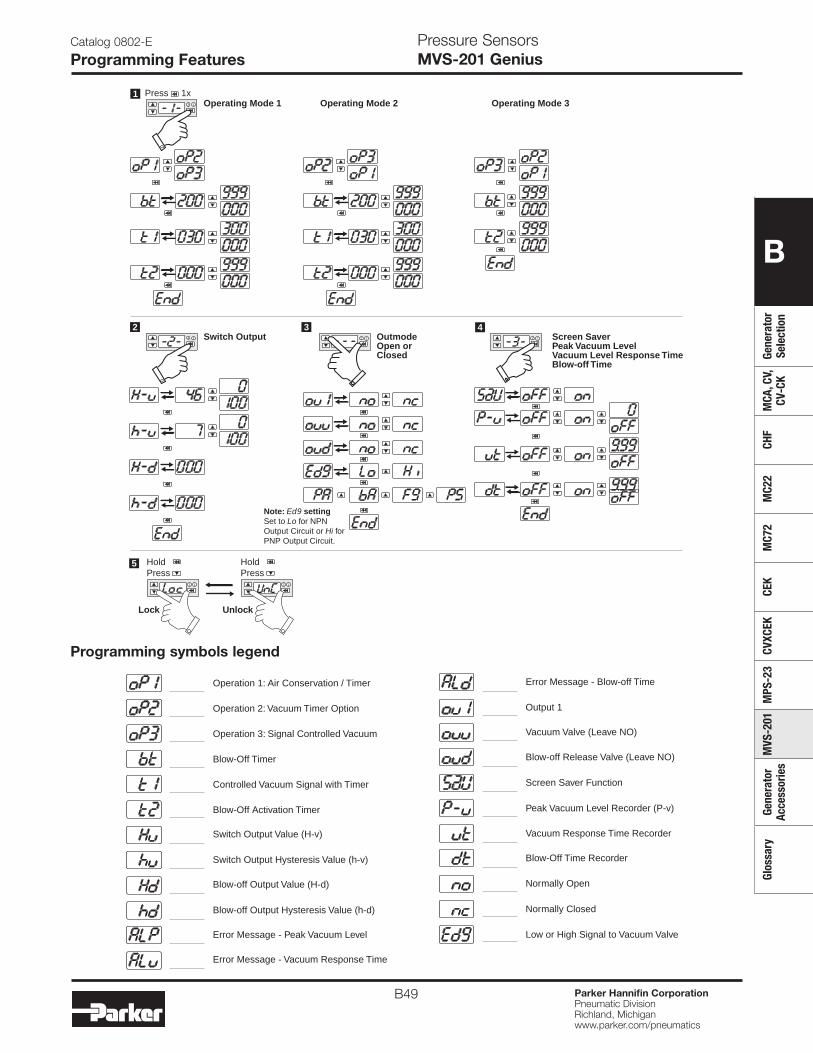
B49 Parker Hannifin CorporationPneumatic DivisionRichland, Michiganwww.parker.com/pneumatics
B
Gene
rato
r Se
lect
ion
MCA
, CV,
CV
-CK
CHF
MC2
2M
C72
CEK
CVXC
EKM
PS-2
3M
VS-2
01Ge
nera
tor
Acce
ssor
ies
Glos
sary
Catalog 0802-E
Programming FeaturesPressure SensorsMVS-201 Genius
2 1
Operating Mode 11
2 1
Press 1xOperating Mode 2 Operating Mode 3
Switch Output4
2 1 OutmodeOpen orClosed
Screen SaverPeak Vacuum LevelVacuum Level Response TimeBlow-off Time
2 32 1
Lock Unlock
5
2 1 2 1
HoldPress
HoldPress
Note: Ed9 settingSet to Lo for NPN Output Circuit or Hi forPNP Output Circuit.
Operation 1: Air Conservation / Timer
Operation 3: Signal Controlled Vacuum
Operation 2: Vacuum Timer Option
Blow-Off Timer
Controlled Vacuum Signal with Timer
Blow-Off Activation Timer
Switch Output Value (H-v)
Switch Output Hysteresis Value (h-v)
Blow-off Output Value (H-d)
Blow-off Output Hysteresis Value (h-d)
Output 1
Vacuum Valve (Leave NO)
Blow-off Release Valve (Leave NO)
Screen Saver Function
Peak Vacuum Level Recorder (P-v)
Vacuum Response Time Recorder
Blow-Off Time Recorder
Normally Open
Normally Closed
Error Message - Peak Vacuum Level
Error Message - Vacuum Response Time
Error Message - Blow-off Time
Low or High Signal to Vacuum Valve
Programming symbols legend
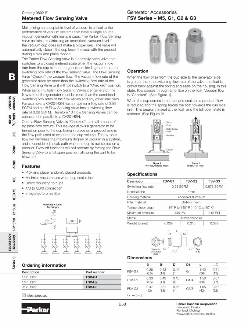
B50 Parker Hannifin CorporationPneumatic DivisionRichland, Michiganwww.parker.com/pneumatics
B
Generator Selection
MCA, CV,
CV-CKCHF
MC22
MC72
CEKCVXCEK
MPS-23
MVS-201
Generator Accessories
Glossary
Catalog 0802-E
Metered Flow Sensing Valve
OperationWhen the flow of air from the cup side to the generator side is greater than the switching flow rate of the valve, the float is drawn back against the spring and seals on the housing. In this state, flow passes through an orifice on the float. Vacuum flow is “Checked”. (See Figure 1).
When the cup comes in contact and seals on a product, flow is reduced and the spring forces the float towards the cup side inlet. This breaks the seal at the float and the full open state is restored. (See Figure 2).
Generator AccessoriesFSV Series – M5, G1, G2 & G3
Maintaining an acceptable level of vacuum is critical to the performance of vacuum systems that have a single source vacuum generator with multiple cups. The Parker Flow Sensing Valve assists in maintaining an acceptable vacuum level if the vacuum cup does not make a proper seal. The valve will automatically close if the cup loses the seal with the product during a pick and place motion.The Parker Flow Sensing Valve is a normally open valve that switches to a closed metered state when the vacuum flow rate from the cup side to the generator side is greater than the switching flow rate of the flow sensing valve. The Flow Sensing Valve “Checks” the vacuum flow. The vacuum flow rate of the generator must be more than the switching flow rate of the Flow Sensing Valve or it will not switch to a “Checked” position.When using multiple Flow Sensing Valves per generator, the flow rate of the generator must be more than the combined switching flow rates of the flow valves and any other leak path. For example, a CV20-HSN has a maximum flow rate of 3.88 SCFM and a 1/8 Flow Sensing Valve has a switching flow rate of 0.28 SCFM. Therefore 13 Flow Sensing Valves can be connected in parallel to a CV20-HSN.Once a Flow Sensing Valve is “Checked”, a small amount of by-pass flow occurs. This leakage allows a generator to be turned on prior to the cup being in place on a product and is the flow path used to evacuate the cup volume. The by-pass flow will decrease the maximum degree of vacuum in a system, and is considered a leak path when the cup is not sealed on a product. Blow off functions will still operate by forcing the Flow Sensing Valve to a full open position, allowing the part to be blown off.
Features• Pick and place randomly placed products • Minimize vacuum loss when cup seal is lost• Direct mounting to cups• 1/8 to G3/8 connection • Integrated bronze filter
Normally ClosedAir Supply
Suction Cup
Housing
Filter
Float
Meter Orifice
Spring
Figure 1(Closed, Metered Flow)
Figure 2(Open, Full Flow)
DimensionsB B1 D D1 L
FSV-G1 0.26 (6.5)
0.43 (11)
0.16 (4) G 1.42
(36)0.51 (13)
FSV-G2 0.33 (8.5)
0.43 (11)
0.16 (4) G1/4 1.50
(38)0.67 (17)
FSV-G3 0.47 (12)
0.51 (13)
0.16 (4) G3/8 1.65
(42)0.87 (22)
inches (mm)
Specifications
Description FSV-G1 FSV-G2 FSV-G3
Switching flow rate 0.28 SCFM 0.875 SCFM
Nominal size 4mm
Housing material Anodized aluminum
Filter material Al-Niro mesh
Temperature range 14° F to 140° F (-10° C to 60° C)
Maximum pressure 145 PSI 115 PSI
Media Atmospheric air
Weight (grams) 0.009 0.016 0.029
Ordering information Description Part number
1/8" BSPP FSV-G1
1/4" BSPP FSV-G2
3/8" BSPP FSV-G3
B1B
D
L
VacuumGenerator
Side
CupSide
D1 D1
Most popular.
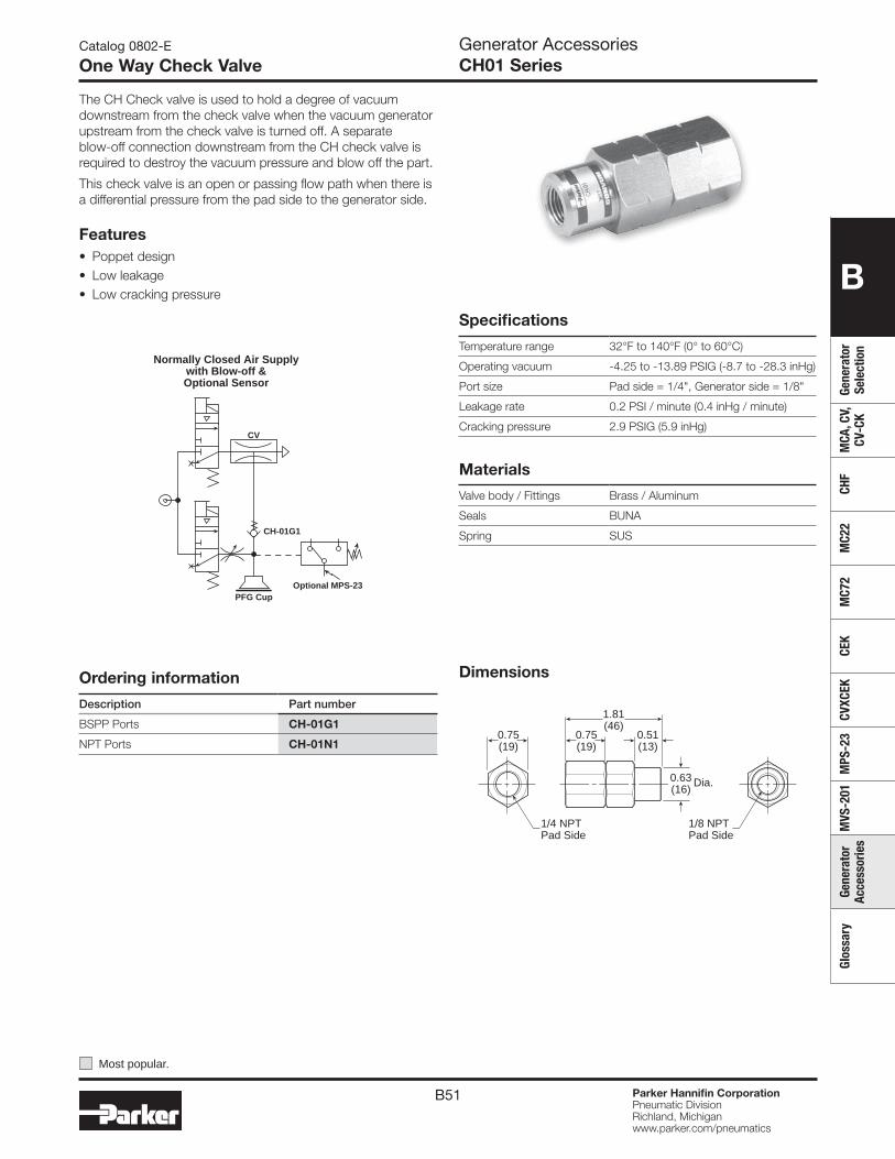
B51 Parker Hannifin CorporationPneumatic DivisionRichland, Michiganwww.parker.com/pneumatics
B
Gene
rato
r Se
lect
ion
MCA
, CV,
CV
-CK
CHF
MC2
2M
C72
CEK
CVXC
EKM
PS-2
3M
VS-2
01Ge
nera
tor
Acce
ssor
ies
Glos
sary
Generator AccessoriesCH01 Series
Catalog 0802-E
One Way Check Valve
Specifications
Temperature range 32°F to 140°F (0° to 60°C)
Operating vacuum -4.25 to -13.89 PSIG (-8.7 to -28.3 inHg)
Port size Pad side = 1/4", Generator side = 1/8"
Leakage rate 0.2 PSI / minute (0.4 inHg / minute)
Cracking pressure 2.9 PSIG (5.9 inHg)
Materials
Valve body / Fittings Brass / Aluminum
Seals BUNA
Spring SUS
Ordering information
Description Part number
BSPP Ports CH-01G1
NPT Ports CH-01N10.51 (13)
0.75 (19)
0.63 (16)
0.75 (19)
1.81 (46)
1/4 NPT Pad Side
1/8 NPT Pad Side
Dia.
Dimensions
The CH Check valve is used to hold a degree of vacuum downstream from the check valve when the vacuum generator upstream from the check valve is turned off. A separate blow-off connection downstream from the CH check valve is required to destroy the vacuum pressure and blow off the part.
This check valve is an open or passing flow path when there is a differential pressure from the pad side to the generator side.
Features• Poppet design• Low leakage• Low cracking pressure
CH-01G1
PFG CupOptional MPS-23
CV
Normally Closed Air Supplywith Blow-off &Optional Sensor
Most popular.
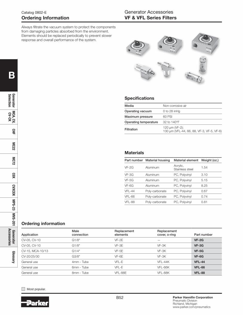
B52 Parker Hannifin CorporationPneumatic DivisionRichland, Michiganwww.parker.com/pneumatics
B
Generator Selection
MCA, CV,
CV-CKCHF
MC22
MC72
CEKCVXCEK
MPS-23
MVS-201
Generator Accessories
Glossary
Catalog 0802-E
Ordering InformationGenerator AccessoriesVF & VFL Series Filters
Materials
Part number Material housing Material element Weight (oz.)
VF-2G Aluminum Acrylic, Stainless steel 1.54
VF-3G Aluminum PC, Polyvinyl 3.10
VF-5G Aluminum PC, Polyvinyl 5.15
VF-6G Aluminum PC, Polyvinyl 8.25
VFL-44 Poly-carbonate PC, Polyvinyl 0.67
VFL-66 Poly-carbonate PC, Polyvinyl 0.74
VFL-88 Poly-carbonate PC, Polyvinyl 0.81
Ordering information
ApplicationMale connection
Replacement elements
Replacementcover, o-ring Part number
CV-05, CV-10 G1/8" VF-2E — VF-2G
CV-05, CV-10 G1/8" VF-3E VF-3K VF-3G
CV-15, MCA-10/13 G1/4" VF-5E VF-3K VF-5G
CV-20/25/30 G3/8" VF-6E VF-3K VF-6G
General use 4mm - Tube VFL-E VFL-44K VFL-44
General use 6mm - Tube VFL-E VFL-66K VFL-66
General use 8mm - Tube VFL-88E VFL-88K VFL-88
Specifications
Media Non-corrosive air
Operating vacuum 0 to 28 inHg
Maximum pressure 60 PSI
Operating temperature 32 to 140°F
Filtration 120 µm (VF-2); 130 µm (VFL-44, 66, 88, VF-3, VF-5, VF-6)
Always filtrate the vacuum system to protect the components from damaging particles absorbed from the environment. Elements should be replaced periodically to prevent slower response and overall performance of the system.
Most popular.
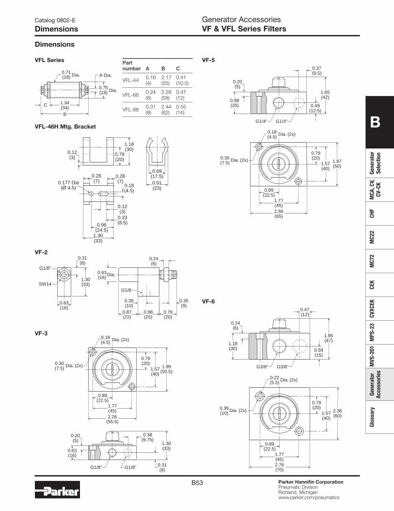
B53 Parker Hannifin CorporationPneumatic DivisionRichland, Michiganwww.parker.com/pneumatics
B
Gene
rato
r Se
lect
ion
MCA
, CV,
CV
-CK
CHF
MC2
2M
C72
CEK
CVXC
EKM
PS-2
3M
VS-2
01Ge
nera
tor
Acce
ssor
ies
Glos
sary
Catalog 0802-E
DimensionsGenerator AccessoriesVF & VFL Series Filters
Dimensions
B
1.34 (34)C
0.71 (18) Dia.
0.75 (19) Dia.
A Dia.
VFL Series
VF-2
0.63 (16)
0.87 (22)
0.98 (25)
0.39 (10)
0.35(9)
0.24 (6)
0.79 (20)
0.63 (16)1.30
(33)
0.31 (8)
SW14
G1/8"Dia.
G1/8
1.57(40)
1.30(33)
0.79(20)
0.63(16)
0.31(8)
0.20 (5)
1.99(50.5)
2.26 (55.5)
1.77 (45)
0.89 (22.5)
0.38 (9.75)
0.18(4.5) Dia. (2x)
0.30(7.5) Dia. (2x)
G1/8" G1/8"
VF-3
VF-5
1.57(40)
1.65(42)
0.79(20)
0.98(25) 0.49
(12.5)
0.20 (5)
1.97(50)
2.56 (65)
1.77 (45)
0.89 (22.5)
0.37 (9.5)
0.18(4.5) Dia. (2x)
0.30(7.5) Dia. (2x)
G1/4" G1/4"
1.57(40)
1.85(47)
0.79(20)
1.18(30) 0.59
(15)
0.24(6)
2.36(60)
1.77 (45)2.76 (70)
0.89 (22.5)
0.47 (12)
0.22(5.5) Dia. (2x)
0.39(10) Dia. (2x)
G3/8" G3/8"
VF-6
0.69 (17.5)
1.18 (30)
0.79 (20)
0.12(3)
0.177 Dia(Ø 4.5)
0.28(7)
0.18(4.5)
0.91(23)
1.30(33)
0.96(24.5)
0.28(7)
0.33(8.5)
0.12(3)
VFL-46H Mtg. Bracket
Part number A B C
VFL-44 0.16(4)
2.17(55)
0.41(10.5)
VFL-66 0.24(6)
2.28(58)
0.47(12)
VFL-88 0.31(8)
2.44(62)
0.55(14)
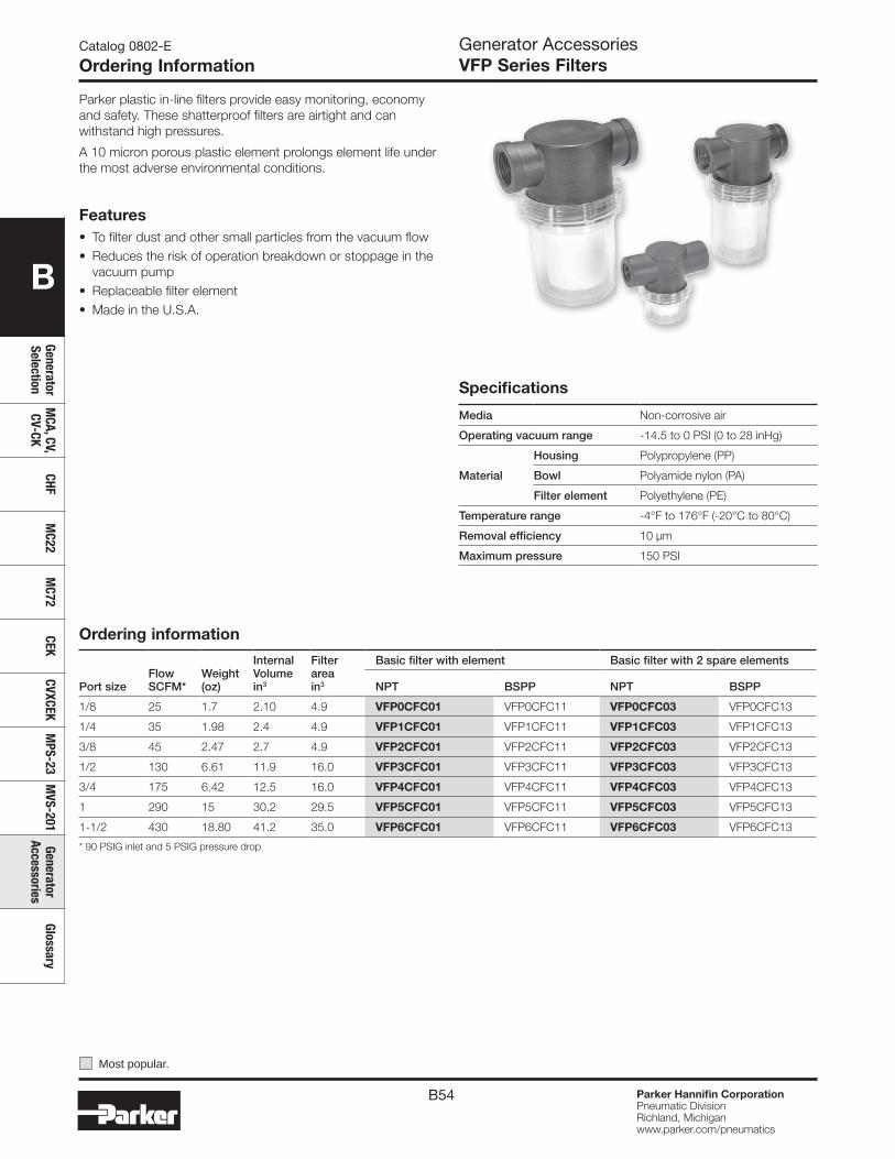
B54 Parker Hannifin CorporationPneumatic DivisionRichland, Michiganwww.parker.com/pneumatics
B
Generator Selection
MCA, CV,
CV-CKCHF
MC22
MC72
CEKCVXCEK
MPS-23
MVS-201
Generator Accessories
Glossary
Catalog 0802-E
Ordering InformationGenerator AccessoriesVFP Series Filters
Parker plastic in-line filters provide easy monitoring, economy and safety. These shatterproof filters are airtight and can withstand high pressures.
A 10 micron porous plastic element prolongs element life under the most adverse environmental conditions.
Specifications
Media Non-corrosive air
Operating vacuum range -14.5 to 0 PSI (0 to 28 inHg)
Material
Housing Polypropylene (PP)
Bowl Polyamide nylon (PA)
Filter element Polyethylene (PE)
Temperature range -4°F to 176°F (-20°C to 80°C)
Removal efficiency 10 µm
Maximum pressure 150 PSI
Most popular.
Ordering information
Port sizeFlow SCFM*
Weight (oz)
Internal Volumein3
Filter areain3
Basic filter with element Basic filter with 2 spare elements
NPT BSPP NPT BSPP
1/8 25 1.7 2.10 4.9 VFP0CFC01 VFP0CFC11 VFP0CFC03 VFP0CFC13
1/4 35 1.98 2.4 4.9 VFP1CFC01 VFP1CFC11 VFP1CFC03 VFP1CFC13
3/8 45 2.47 2.7 4.9 VFP2CFC01 VFP2CFC11 VFP2CFC03 VFP2CFC13
1/2 130 6.61 11.9 16.0 VFP3CFC01 VFP3CFC11 VFP3CFC03 VFP3CFC13
3/4 175 6.42 12.5 16.0 VFP4CFC01 VFP4CFC11 VFP4CFC03 VFP4CFC13
1 290 15 30.2 29.5 VFP5CFC01 VFP5CFC11 VFP5CFC03 VFP5CFC13
1-1/2 430 18.80 41.2 35.0 VFP6CFC01 VFP6CFC11 VFP6CFC03 VFP6CFC13
* 90 PSIG inlet and 5 PSIG pressure drop
Features• To filter dust and other small particles from the vacuum flow• Reduces the risk of operation breakdown or stoppage in the
vacuum pump• Replaceable filter element• Made in the U.S.A.
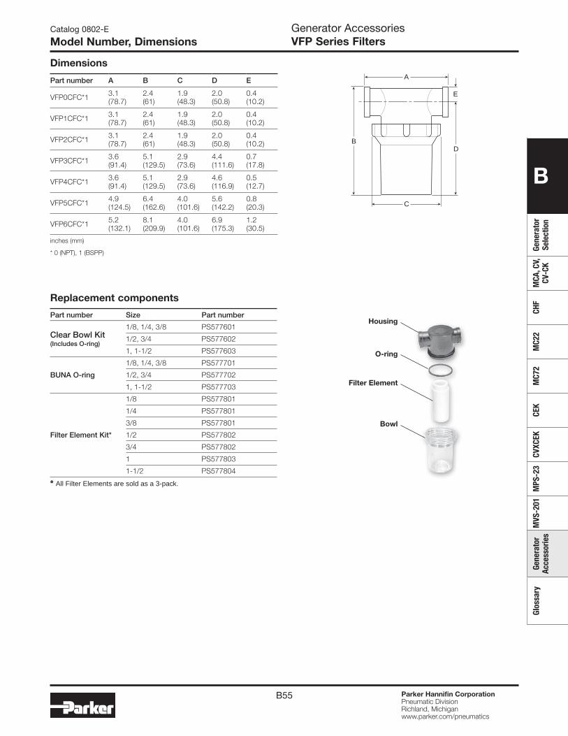
B55 Parker Hannifin CorporationPneumatic DivisionRichland, Michiganwww.parker.com/pneumatics
B
Gene
rato
r Se
lect
ion
MCA
, CV,
CV
-CK
CHF
MC2
2M
C72
CEK
CVXC
EKM
PS-2
3M
VS-2
01Ge
nera
tor
Acce
ssor
ies
Glos
sary
Catalog 0802-E
Model Number, DimensionsGenerator AccessoriesVFP Series Filters
Dimensions
Part number A B C D E
VFP0CFC*1 3.1 (78.7)
2.4 (61)
1.9(48.3)
2.0(50.8)
0.4(10.2)
VFP1CFC*1 3.1 (78.7)
2.4 (61)
1.9(48.3)
2.0(50.8)
0.4(10.2)
VFP2CFC*1 3.1(78.7)
2.4 (61)
1.9(48.3)
2.0(50.8)
0.4(10.2)
VFP3CFC*1 3.6 (91.4)
5.1 (129.5)
2.9 (73.6)
4.4 (111.6)
0.7(17.8)
VFP4CFC*1 3.6 (91.4)
5.1 (129.5)
2.9 (73.6)
4.6 (116.9)
0.5(12.7)
VFP5CFC*1 4.9 (124.5)
6.4 (162.6)
4.0 (101.6)
5.6 (142.2)
0.8(20.3)
VFP6CFC*1 5.2 (132.1)
8.1 (209.9)
4.0 (101.6)
6.9 (175.3)
1.2(30.5)
inches (mm)
* 0 (NPT), 1 (BSPP)
Housing
O-ring
Filter Element
Bowl
A
E
C
BD
Replacement components
Part number Size Part number
Clear Bowl Kit (Includes O-ring)
1/8, 1/4, 3/8 PS577601
1/2, 3/4 PS577602
1, 1-1/2 PS577603
BUNA O-ring
1/8, 1/4, 3/8 PS577701
1/2, 3/4 PS577702
1, 1-1/2 PS577703
Filter Element Kit*
1/8 PS577801
1/4 PS577801
3/8 PS577801
1/2 PS577802
3/4 PS577802
1 PS577803
1-1/2 PS577804
* All Filter Elements are sold as a 3-pack.
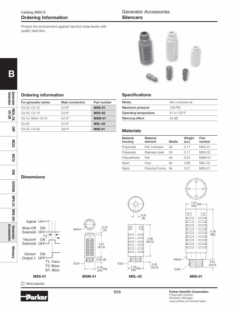
B56 Parker Hannifin CorporationPneumatic DivisionRichland, Michiganwww.parker.com/pneumatics
B
Generator Selection
MCA, CV,
CV-CKCHF
MC22
MC72
CEKCVXCEK
MPS-23
MVS-201
Generator Accessories
Glossary
Catalog 0802-E
Ordering InformationGenerator AccessoriesSilencers
Protect the environment against harmful noise levels with quality silencers.
Ordering information
For generator series Male connection Part number
CV-05, CV-10 G1/8" MSS-01
CV-05, CV-10 G1/8" MSS-02
CV-15, MCA-10/13 G1/4" MSM-01
CV-20 G1/2" MSL-02
CV-25, CV-30 G3/4" MS6-01
Specifications
Media Non-corrosive air
Maximum pressure 128 PSI
Operating temperature 41 to 132°F
Silencing effect 20 dB
Materials
Material housing
Material element Media
Weight (oz.)
Part number
Polyacetal Felt, Urethane Air 0.17 MSS-01
Polyacetal Stainless steel Oil 0.17 MSS-02
Polyurethane Felt Air 0.24 MSM-01
Nylon Vinyl Air 0.88 MSL-02
Nylon Polyvinyl Forma Air 2.01 MS6-01
3.78(96)
0.57(14.5)
G3/4
SW32
1.57(40)
Dia.
2.38(60.5)
0.41(10.5)
G1/21.18 (30)
0.31(8)
Dia.
1.67(42.5)
SW14
G1/4
0.12(3)
0.35 (9)
0.79 (20) Dia.
PSI
inHg
(P-u) Peak ValueON (H-u) Vacuum
OFF (h-u)
OFF (h-d)
ON (H-d) Blow-Off
InputSignal
ONOFF
ONOFF
ONOFF
ONOFF
Blow-OffSolenoid
VacuumSolenoid
Sensor Output 1
T1: Vacuum TimerT2: Blow-Off Delay TimerBT: Blow-Off Timer
Mode: OP1 "Air Conservation / Timer
T1
ut
T1
dt
T2 BT
Dimensions
MSS-01 MSM-01 MSL-02 MS6-01
Most popular.
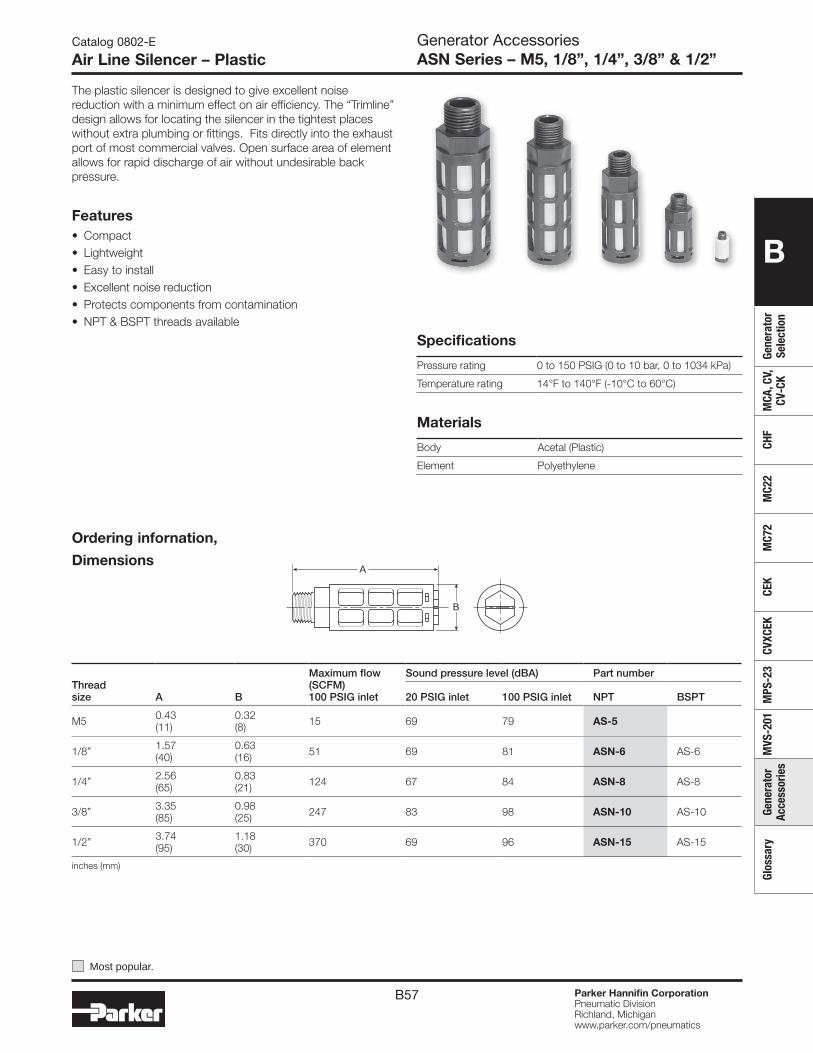
B57 Parker Hannifin CorporationPneumatic DivisionRichland, Michiganwww.parker.com/pneumatics
B
Gene
rato
r Se
lect
ion
MCA
, CV,
CV
-CK
CHF
MC2
2M
C72
CEK
CVXC
EKM
PS-2
3M
VS-2
01Ge
nera
tor
Acce
ssor
ies
Glos
sary
Generator AccessoriesASN Series – M5, 1/8”, 1/4”, 3/8” & 1/2”
Catalog 0802-E
Air Line Silencer – Plastic
The plastic silencer is designed to give excellent noise reduction with a minimum effect on air efficiency. The “Trimline” design allows for locating the silencer in the tightest places without extra plumbing or fittings. Fits directly into the exhaust port of most commercial valves. Open surface area of element allows for rapid discharge of air without undesirable back pressure.
Specifications
Pressure rating 0 to 150 PSIG (0 to 10 bar, 0 to 1034 kPa)
Temperature rating 14°F to 140°F (-10°C to 60°C)
Materials
Body Acetal (Plastic)
Element Polyethylene
Threadsize A B
Maximum flow (SCFM)100 PSIG inlet
Sound pressure level (dBA) Part number
20 PSIG inlet 100 PSIG inlet NPT BSPT
M5 0.43(11)
0.32(8) 15 69 79 AS-5
1/8” 1.57(40)
0.63(16) 51 69 81 ASN-6 AS-6
1/4” 2.56(65)
0.83(21) 124 67 84 ASN-8 AS-8
3/8” 3.35(85)
0.98(25) 247 83 98 ASN-10 AS-10
1/2” 3.74(95)
1.18(30) 370 69 96 ASN-15 AS-15
inches (mm)
Features• Compact • Lightweight • Easy to install • Excellent noise reduction • Protects components from contamination • NPT & BSPT threads available
B
A
Ordering infornation,
Dimensions
Most popular.
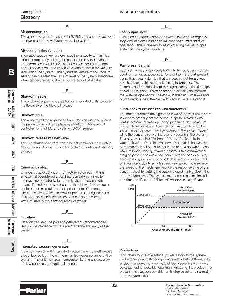
B58 Parker Hannifin CorporationPneumatic DivisionRichland, Michiganwww.parker.com/pneumatics
B
Generator Selection
MCA, CV,
CV-CKCHF
MC22
MC72
CEKCVXCEK
MPS-23
MVS-201
Generator Accessories
Glossary
__A__Air consumptionThe amount of air in (measured in SCFM) consumed to achieve the maximum rated vacuum level of the venturi.
Air-economizing functionIntegrated vacuum generators have the capacity to minimize air consumption by utilizing the built in check valve. Once a predetermined vacuum level has been achieved (with a non-porous application) , the check valve can maintain the vacuum level within the system. The hysteresis feature of the vacuum sensor can maintain the vacuum level of the system indefinitely when properly wired to the vacuum solenoid pilot valve.
__B__Blow-off needleThis is a flow adjustment supplied on integrated units to control the flow rate of the blow-off release.
Blow-off timeThe amount of time required to break the vacuum and release the product in a pick and place application. This is signal controlled by the PLC or by the MVS-201 sensor.
Blow-off release master valveThis is a shuttle valve that works by differential forces which is piloted by a 2-3 valve. This valve is always configured normally closed.
__E__Emergency stopEmergency stop conditions for factory automation; this is an external override condition that is usually activated by the machine operator to temporarily shut the equipment down. The relevance to vacuum is the ability of the vacuum equipment to maintain the last output state of the control circuit. This feature would prevent part loss during this event as a normally closed system could maintain the current vacuum state without the presence of power.
__F__FiltrationFiltration between the pad and generator is recommended. Regular maintenance of filters maintains the efficiency of the system.
__I__Integrated vacuum generatorA vacuum venturi with integrated vacuum and blow-off release pilot valves built on the unit to minimize response times of the system. The unit may also incorporate filters, silencers, blow-off flow controls , and optional sensors.
__L__Last output stateDuring an emergency stop or power loss event, emergency stop circuits from Parker can maintain the current state of operation. This is referred to as maintaining the last output state from the system controls.
__P__Part present signalEach sensor has an available NPN / PNP output and can be used for numerous purposes. One of them is a part present signal that usually signifies that a preset output for a vacuum level has been achieved and it is safe to proceed. The accuracy and repeatability of this signal can be critical to high speed applications. False or dropped signals can interrupt the systems operations. Therefore, stable vacuum levels and output settings near the “part-off” vacuum level are critical.
“Part-on” / “Part-off” vacuum differentialYou must determine the highs and lows of the vacuum system in order to properly set the sensor outputs. Typically with venturi systems at fixed operating pressures, the maximum vacuum level is known. The “Part-off” vacuum level of the system must be determined by operating the system “open” while the sensor displays the level of vacuum in the system. This is known as the “Part/on” / “Part-off” differential in vacuum levels. Once this window of vacuum is known, the part present signal could be set in the middle between these vacuum levels. Ideally, it would be best if this window was a big as possible to avoid any issues with the sensors. Yet, sometimes by design or necessity, this window is very small or insignificant due to a high speed operation. To maximize the speed of the machinery, reduce the response time of the sensor output by setting the output around 1 inHg above the open vacuum level. The system response time is minimized and thus the “Part-on” / “Part-off” window is insignificant.
Power loss This refers to loss of electrical power supply to the system. Unlike other pneumatic components with safety features, loss of electrical power to a normally closed vacuum circuit could be catastrophic; possibly resulting in dropping the product. To prevent this situation, consider an E-stop circuit or a normally open vacuum circuit.
Catalog 0802-E
GlossaryVacuum Generators
0 100 200
-30inHg “Part-On”
Vacuum Level
“Part-Off”Vacuum Level
Output Range
Upper Limit
Lower Limit
Output Response Time (msec)
B59 Parker Hannifin CorporationPneumatic DivisionRichland, Michiganwww.parker.com/pneumatics
B
Gene
rato
r Se
lect
ion
MCA
, CV,
CV
-CK
CHF
MC2
2M
C72
CEK
CVXC
EKM
PS-2
3M
VS-2
01Ge
nera
tor
Acce
ssor
ies
Glos
sary
Pressure sensorA piezo resistive sensor used to monitor pressure levels in the system. The sensors supply NPN/PNP open collector transistor outputs back to the PLC for confirmation.
__R__Response timeThe time to evacuate the air out of a closed system to a certain vacuum level. This is critical to the overall performance of the vacuum system.
__T__ThreadsNPT (National Pipe Taper) BSPT (British Standard Pipe Taper)BSPP (British Standard Pipe Parallel)G (Gaus)M (Metric)NPS (Dry Seal American Standard Fuel Internal Straight Pipe)
__V__Vacuum Any reference to vacuum or negative pressures could be defined as a force applied to a closed system by the difference in the number of air molecules within a chamber, enclosure, piping system, etc. to the number of air molecules outside of these systems or enclosures. The outside atmospheric pressure is larger and applies a force to the lesser pressures in the systems or enclosures. Therefore, vacuum is a differential pressure whereby atmosphere is the reference and external force.
Vacuum confirmationTerm used to describe an output signal NPN/PNP from the sensor to the PLC when the suction cup has made a proper seal with the product before transfer. This verifies that the vacuum level is safe to proceed.
Vacuum flowRepresented as SCFM, this is the rate at which air molecules can be evacuated through a venturi system.
Vacuum generator This is sometimes referred to as an ejector. The venturi generates vacuum with compressed air by evacuating air molecules from a closed system.
Vacuum release pilot valveAlso referred to as Discharge valve, this valve pilots the Blow-off release master valve to effectively release the product during pick and place applications. This function is essential to high speed applications.
Vacuum master valveThis is a shuttle valve that works by differential forces which is piloted by a 2-3 valve. This valve can be configured normally closed or open.
Catalog 0802-E
GlossaryVacuum Generators

B60 Parker Hannifin CorporationPneumatic DivisionRichland, Michiganwww.parker.com/pneumatics
B
Generator Selection
MCA, CV,
CV-CKCHF
MC22
MC72
CEKCVXCEK
MPS-23
MVS-201
Generator Accessories
Glossary
Catalog 0802-E
NotesVacuum Generators
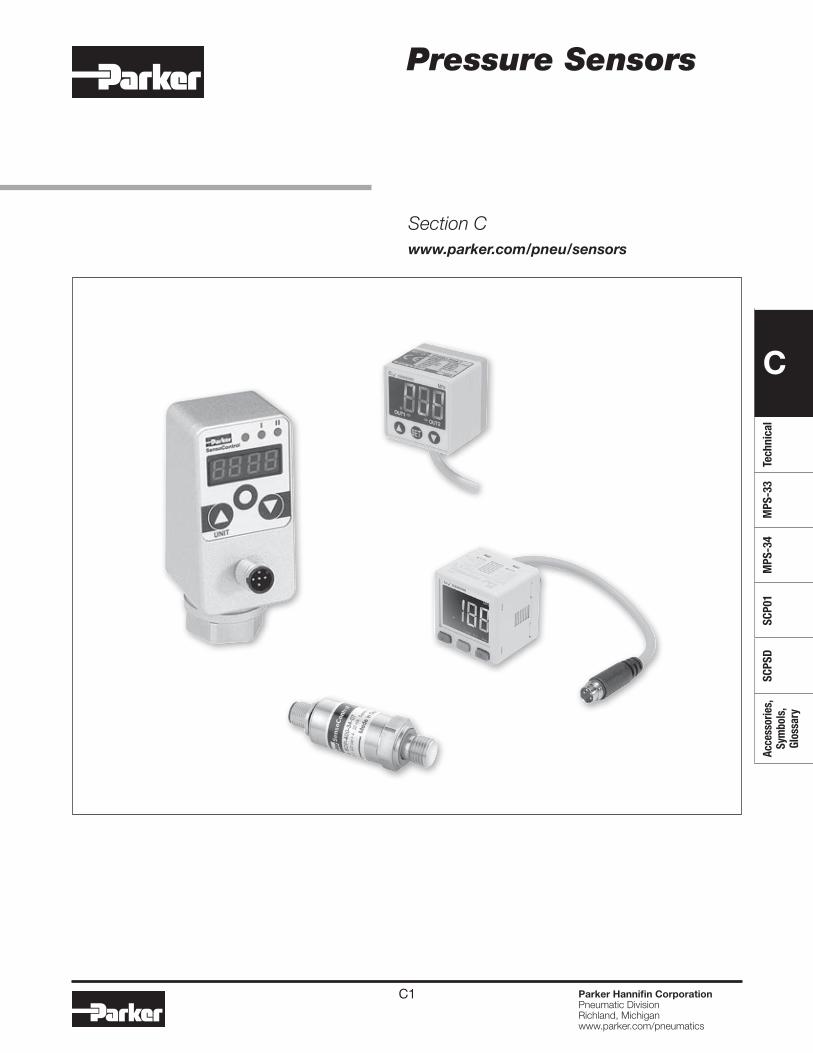
C1 Parker Hannifin CorporationPneumatic DivisionRichland, Michiganwww.parker.com/pneumatics
C
Tech
nica
lM
PS-3
3M
PS-3
4SC
P01
SCPS
DAc
cess
orie
s,
Sym
bols
, Gl
ossa
ry
Pressure Sensors
Section Cwww.parker.com/pneu/sensors
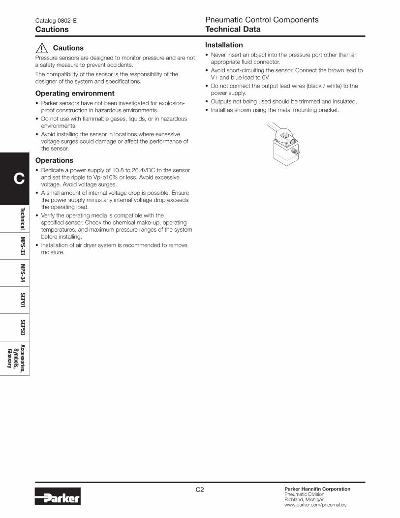
C2 Parker Hannifin CorporationPneumatic DivisionRichland, Michiganwww.parker.com/pneumatics
C
TechnicalM
PS-33M
PS-34SCP01
SCPSDAccessories,
Symbols,
Glossary
Pneumatic Control ComponentsTechnical Data
Catalog 0802-E
Cautions
BarbCouplingO-Ring
Ambient AirInlet Port
–INCLUDED–
Pipe Plug
CautionsPressure sensors are designed to monitor pressure and are not a safety measure to prevent accidents.
The compatibility of the sensor is the responsibility of the designer of the system and specifications.
Operating environment• Parker sensors have not been investigated for explosion-
proof construction in hazardous environments.• Do not use with flammable gases, liquids, or in hazardous
environments.• Avoid installing the sensor in locations where excessive
voltage surges could damage or affect the performance of the sensor.
Operations• Dedicate a power supply of 10.8 to 26.4VDC to the sensor
and set the ripple to Vp-p10% or less. Avoid excessive voltage. Avoid voltage surges.
• A small amount of internal voltage drop is possible. Ensure the power supply minus any internal voltage drop exceeds the operating load.
• Verify the operating media is compatible with the specified sensor. Check the chemical make-up, operating temperatures, and maximum pressure ranges of the system before installing.
• Installation of air dryer system is recommended to remove moisture.
Installation• Never insert an object into the pressure port other than an
appropriate fluid connector.• Avoid short-circuiting the sensor. Connect the brown lead to
V+ and blue lead to 0V.• Do not connect the output lead wires (black / white) to the
power supply.• Outputs not being used should be trimmed and insulated.• Install as shown using the metal mounting bracket.
!
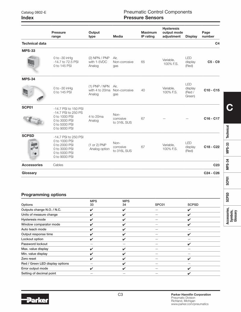
C3 Parker Hannifin CorporationPneumatic DivisionRichland, Michiganwww.parker.com/pneumatics
C
Tech
nica
lM
PS-3
3M
PS-3
4SC
P01
SCPS
DAc
cess
orie
s,
Sym
bols
, Gl
ossa
ry
Pneumatic Control ComponentsPressure Sensors
Catalog 0802-E
Index
Pressurerange
Outputtype Media
MaximumIP rating
Hysteresis output modeadjustment Display
Pagenumber
Technical data C4
MPS-33
0 to -30 inHg -14.7 to 72.5 PSI 0 to 145 PSI
(2) NPN / PNP with 1-5VDC Analog
Air,Non-corrosivegas
65 Variable, 100% F.S.
LED display(Red)
C5 - C9
MPS-34
0 to -30 inHg 0 to 145 PSI
(1) PNP / NPNwith 4 to 20ma Analog
Air, Non-corrosivegas
40 Variable, 100% F.S.
LED display (Red / Green)
C10 - C15
SCP01 -14.7 PSI to 150 PSI -14.7 PSI to 250 PS0 to 1000 PSI 0 to 3000 PSI 0 to 5000 PSI0 to 9000 PSI
4 to 20ma Analog
Non- corrosiveto 316L SUS
67 — — C16 - C17
SCPSD -14.7 PSI to 250 PSI0 to 1000 PSI0 to 2000 PSI 0 to 3000 PSI 0 to 5000 PSI0 to 9000 PSI
(1 or 2) PNP Analog option
Non- corrosiveto 316L SUS
67 Variable, 100% F.S.
LED display(Red)
C18 - C22
Accessories Cables C23
Glossary C24 - C26
Programming options
OptionsMPS 33
MPS 34 SPC01 SCPSD
Outputs change N.O. / N.C. 4 4 — 4
Units of measure change 4 4 — 4
Hysteresis mode 4 4 — 4
Window comparator mode 4 4 — 4
Auto teach mode 4 4 — —
Output response time 4 4 — 4
Lockout option 4 4 — —
Password lockout — — — 4
Max. value display 4 4 — —
Min. value display 4 4 — —
Zero reset 4 4 — 4
Red / Green LED display options — 4 — —
Error output mode 4 4 — 4
Setting of decimal point — — — 4
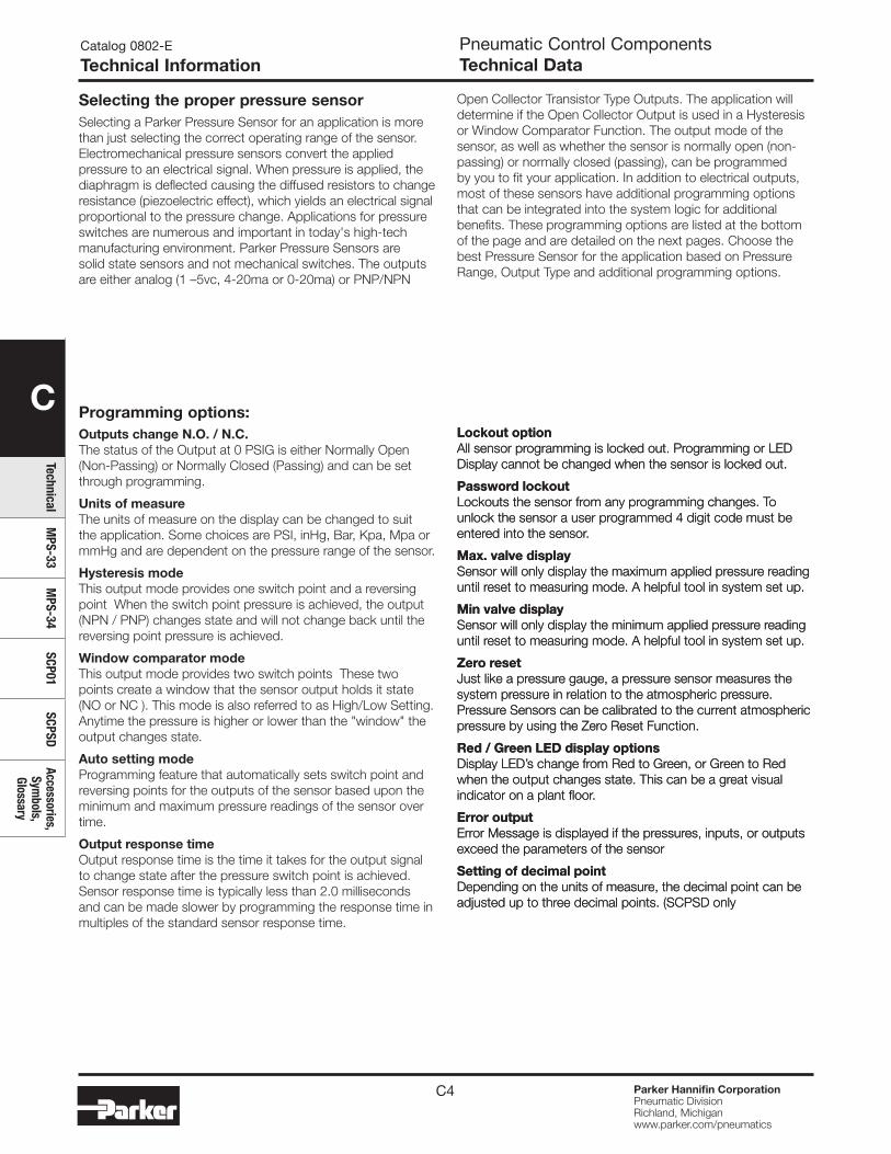
C4 Parker Hannifin CorporationPneumatic DivisionRichland, Michiganwww.parker.com/pneumatics
C
TechnicalM
PS-33M
PS-34SCP01
SCPSDAccessories,
Symbols,
Glossary
Pneumatic Control ComponentsTechnical Data
Catalog 0802-E
Technical Information
Selecting the proper pressure sensorSelecting a Parker Pressure Sensor for an application is more than just selecting the correct operating range of the sensor. Electromechanical pressure sensors convert the applied pressure to an electrical signal. When pressure is applied, the diaphragm is deflected causing the diffused resistors to change resistance (piezoelectric effect), which yields an electrical signal proportional to the pressure change. Applications for pressure switches are numerous and important in today's high-tech manufacturing environment. Parker Pressure Sensors are solid state sensors and not mechanical switches. The outputs are either analog (1 –5vc, 4-20ma or 0-20ma) or PNP/NPN
Open Collector Transistor Type Outputs. The application will determine if the Open Collector Output is used in a Hysteresis or Window Comparator Function. The output mode of the sensor, as well as whether the sensor is normally open (non-passing) or normally closed (passing), can be programmed by you to fit your application. In addition to electrical outputs, most of these sensors have additional programming options that can be integrated into the system logic for additional benefits. These programming options are listed at the bottom of the page and are detailed on the next pages. Choose the best Pressure Sensor for the application based on Pressure Range, Output Type and additional programming options.
Outputs change N.O. / N.C.The status of the Output at 0 PSIG is either Normally Open (Non-Passing) or Normally Closed (Passing) and can be set through programming.
Units of measureThe units of measure on the display can be changed to suit the application. Some choices are PSI, inHg, Bar, Kpa, Mpa or mmHg and are dependent on the pressure range of the sensor.
Hysteresis modeThis output mode provides one switch point and a reversing point When the switch point pressure is achieved, the output (NPN / PNP) changes state and will not change back until the reversing point pressure is achieved.
Window comparator modeThis output mode provides two switch points These two points create a window that the sensor output holds it state (NO or NC ). This mode is also referred to as High/Low Setting. Anytime the pressure is higher or lower than the "window" the output changes state.
Auto setting modeProgramming feature that automatically sets switch point and reversing points for the outputs of the sensor based upon the minimum and maximum pressure readings of the sensor over time.
Output response timeOutput response time is the time it takes for the output signal to change state after the pressure switch point is achieved. Sensor response time is typically less than 2.0 milliseconds and can be made slower by programming the response time in multiples of the standard sensor response time.
Lockout optionAll sensor programming is locked out. Programming or LED Display cannot be changed when the sensor is locked out.
Password lockoutLockouts the sensor from any programming changes. To unlock the sensor a user programmed 4 digit code must be entered into the sensor.
Max. valve displaySensor will only display the maximum applied pressure reading until reset to measuring mode. A helpful tool in system set up.
Min valve displaySensor will only display the minimum applied pressure reading until reset to measuring mode. A helpful tool in system set up.
Zero resetJust like a pressure gauge, a pressure sensor measures the system pressure in relation to the atmospheric pressure. Pressure Sensors can be calibrated to the current atmospheric pressure by using the Zero Reset Function.
Red / Green LED display optionsDisplay LED’s change from Red to Green, or Green to Red when the output changes state. This can be a great visual indicator on a plant floor.
Error outputError Message is displayed if the pressures, inputs, or outputs exceed the parameters of the sensor
Setting of decimal pointDepending on the units of measure, the decimal point can be adjusted up to three decimal points. (SCPSD only
Programming options:
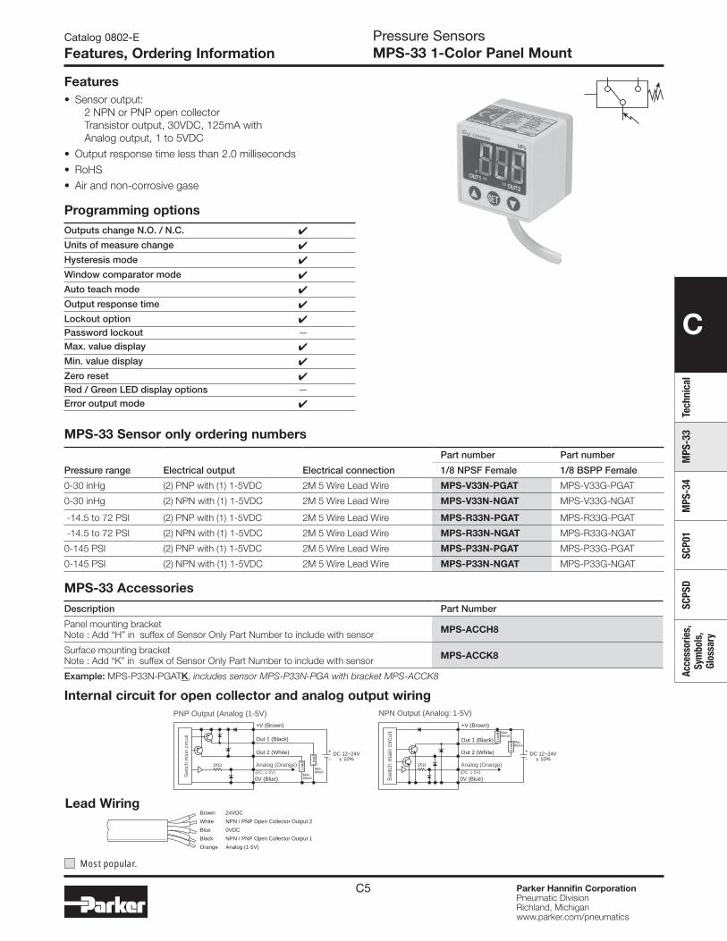
C
Tech
nica
lM
PS-3
3M
PS-3
4SC
P01
SCPS
DAc
cess
orie
s,
Sym
bols
, Gl
ossa
ry
C5 Parker Hannifin CorporationPneumatic DivisionRichland, Michiganwww.parker.com/pneumatics
Catalog 0802-E
Features, Ordering InformationPressure SensorsMPS-33 1-Color Panel Mount
Features• Sensor output:
2 NPN or PNP open collector Transistor output, 30VDC, 125mA with Analog output, 1 to 5VDC
• Output response time less than 2.0 milliseconds
• RoHS
• Air and non-corrosive gase
MPS-33 Sensor only ordering numbers
Pressure range Electrical output Electrical connection
Part number Part number
1/8 NPSF Female 1/8 BSPP Female
0-30 inHg (2) PNP with (1) 1-5VDC 2M 5 Wire Lead Wire MPS-V33N-PGAT MPS-V33G-PGAT
0-30 inHg (2) NPN with (1) 1-5VDC 2M 5 Wire Lead Wire MPS-V33N-NGAT MPS-V33G-NGAT
-14.5 to 72 PSI (2) PNP with (1) 1-5VDC 2M 5 Wire Lead Wire MPS-R33N-PGAT MPS-R33G-PGAT
-14.5 to 72 PSI (2) NPN with (1) 1-5VDC 2M 5 Wire Lead Wire MPS-R33N-NGAT MPS-R33G-NGAT
0-145 PSI (2) PNP with (1) 1-5VDC 2M 5 Wire Lead Wire MPS-P33N-PGAT MPS-P33G-PGAT
0-145 PSI (2) NPN with (1) 1-5VDC 2M 5 Wire Lead Wire MPS-P33N-NGAT MPS-P33G-NGAT
Sw
itch
mai
n ci
rcui
t
Sw
itch
mai
n ci
rcui
t
0V (Blue)
DC 12~24V± 10%
Out 1 (Black)
Out 2 (White)
Load
Load
+V (Brown)
Analog (Orange)(DC: 1-5V)
0V (Blue)
Out 1 (Black)
Out 2 (White)
+V (Brown)
Analog (Orange)(DC: 1-5V)
1KΩ 1KΩ
NPN Output (Analog: 1-5V)PNP Output (Analog (1-5V)
+
−DC 12~24V
± 10%
+
−
Max.80mA
Load
Load
Max.80mA
Max.80mA
Max.80mA
Internal circuit for open collector and analog output wiring
Lead WiringBrown 24VDC
White NPN / PNP Open Collector Output 2
Blue 0VDC
Black NPN / PNP Open Collector Output 1
Orange Analog (1-5V)
MPS-33 Accessories
Description Part Number
Panel mounting bracket Note : Add “H” in suffex of Sensor Only Part Number to include with sensor MPS-ACCH8
Surface mounting bracket Note : Add “K” in suffex of Sensor Only Part Number to include with sensor MPS-ACCK8
Example: MPS-P33N-PGATK, includes sensor MPS-P33N-PGA with bracket MPS-ACCK8
Most popular.
Programming optionsOutputs change N.O. / N.C. 4
Units of measure change 4
Hysteresis mode 4
Window comparator mode 4
Auto teach mode 4
Output response time 4
Lockout option 4Password lockout —Max. value display 4
Min. value display 4
Zero reset 4Red / Green LED display options —Error output mode 4
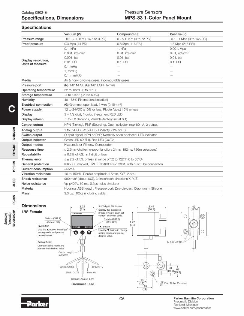
C
TechnicalM
PS-33M
PS-34SCP01
SCPSDAccessories,
Symbols,
Glossary
C6 Parker Hannifin CorporationPneumatic DivisionRichland, Michiganwww.parker.com/pneumatics
Catalog 0802-E
Specifications, DimensionsPressure SensorsMPS-33 1-Color Panel Mount
SpecificationsVacuum (V) Compound (R) Positive (P)
Pressure range -101.3 - 0 kPa (-14.5 to 0 PSI) 0 - 500 kPa (0 to 72 PSI) -0.1 - 1 Mpa (0 to 145 PSI)
Proof pressure 0.3 Mpa (44 PSI) 0.8 Mpa (116 PSI) 1.5 Mpa (218 PSI)
Display resolution, Units of measure
0.1, kPa0.001, kgf/cm2
0.001, bar0.01, PSI0.1, inHg1, mmHg0.1, mmH2O
1, kPa0.01, kgf/cm2
0.01, bar0.1, PSI———
0.001, Mpa0.01, kgf/cm2
0.01, bar0.1, PSI———
Media Air & non-corrosive gases, incombustible gases
Pressure port (N) 1/8" NPSF, (G) 1/8" BSPP female
Operating temperature 32 to 122°F (0 to 50°C)
Storage temperature -4 to 140°F (-20 to 60°C)
Humidity 40 - 85% RH (no condensation)
Electrical connection (G) Grommet open lead, 5 wire (0.15mm2)
Power supply 12 to 24VDC ±10% or less, Ripple (Vp-p) 10% or less
Display 3 + 1/2 digit, 1 color, 7-segment RED LED
Display refresh .1 to 3.0 Seconds, Variable (factory set at 0.1)
Control output NPN (Sinking), PNP (Sourcing), Open collector, max 80mA, 2 output
Analog output 1 to 5VDC ≤ ±2.5% F.S. Linearity ≤1% of F.S.;
Switch output Output signal, NPN or PNP, Normally open or closed, LED indicator
Output indicator Green LED (OUT1), Red LED (OUT2)
Output modes Hysteresis or Window Comparator
Response time ≤ 2.5ms (chattering-proof function: 24ms, 192ms, 786m selections)
Repeatability ± 0.2% of F.S. ± 1 digit or less
Thermal error ≤ ± 2% of F.S. or less at range of 32 to 122°F (0 to 50°C)
General protection IP65, CE marked, EMC-EN61000-6-2: 2001, with dust tube connection
Current consumption <55mA
Vibration resistance 10 to 150Hz, Double amplitude 1.5mm, XYZ, 2 hrs.
Shock resistance 980 m/s² (about 10G), 3 times/each directions X, Y, Z
Noise resistance Vp-p400V, 10 ms, 0.5μs noise simulator
Material Housing: ABS (gray) , Pressure port: Zinc die-cast, Diaphragm: Silicone
Mass 3.3 oz. (105g) (including cable)
1.22(31)
1.22(31)
1.44(36.7)
.49 (12.5)
White: OUT2
Cable Length:1990mm
Brown: +V
Black: OUT1 Blue: 0V
Orange: Analog 1-5V
Grommet Lead
N 1/8 NPSF
Dia. TUbe Connect.12(3)
.61(15.5)
.41(10.5)
.43(11)
.75(19)
Switch (OUT 2)
Setting Button
Change setting mode andpre-set final desired value
3-1/2 digit LED display
Display the measuredpressure value, each setcontent and error code.
(Red LED)
() Button
Use the button to changesetting mode and pre-setdesired value.
() Button
Use the button to changesetting mode and pre-setdesired value.
OUT1
SET
OUT2
Switch (OUT 1)
(Green LED)
Dimensions1/8" Female
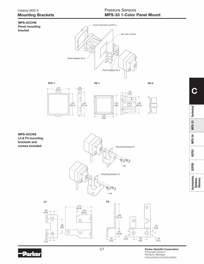
C
Tech
nica
lM
PS-3
3M
PS-3
4SC
P01
SCPS
DAc
cess
orie
s,
Sym
bols
, Gl
ossa
ry
C7 Parker Hannifin CorporationPneumatic DivisionRichland, Michiganwww.parker.com/pneumatics
Pressure SensorsMPS-33 1-Color Panel Mount
Catalog 0802-E
Mounting Brackets
.17(4.2)
.20(5.0)
.20(5.0)
1.03(26.2)
.79(20)
.51(13)
.17(4.2)
.51(12.9)
1.46(37.1)
.24(6.1)
1.79(45.5)
.98(25)
L3 F3
Mounting Bracket F3
M4
M4
Mounting Bracket L3
36 x 36 ± 0.3mm
Panel Adapter PA-1
Front Protective Lid FPC-1
Panel Adapter PA-2
1.67(42.4)
.28(7)
.18(4.5)
1.67(42.4)
1.87(47.4)
1.57(40)
1.57(40)
1.40(35.5)
FPC-1 PA-1 PA-2
MPS-ACCH8Panel mounting bracket
MPS-ACCK8L3 & F3 mounting brackets and screws included
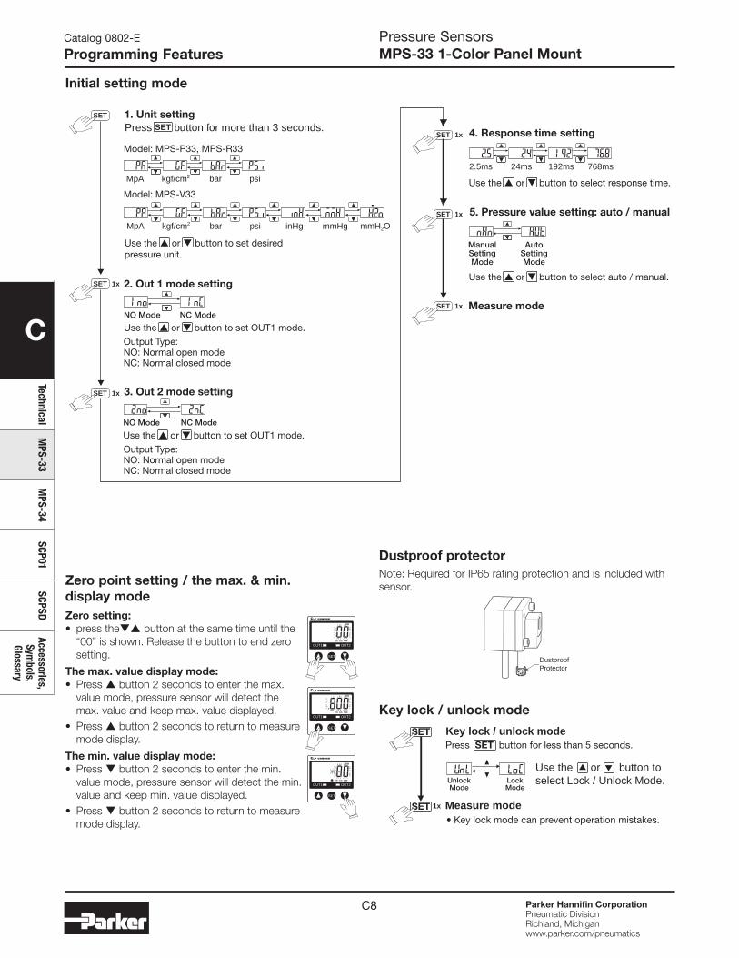
C
TechnicalM
PS-33M
PS-34SCP01
SCPSDAccessories,
Symbols,
Glossary
C8 Parker Hannifin CorporationPneumatic DivisionRichland, Michiganwww.parker.com/pneumatics
Pressure SensorsMPS-33 1-Color Panel Mount
Catalog 0802-E
Programming Features
4. Response time setting
5. Pressure value setting: auto / manual
Measure mode
Output Type: NO: Normal open modeNC: Normal closed mode
Model: MPS-V33
Use the or button to set desiredpressure unit.
Use the or button to select response time.
Use the or button to select auto / manual.
Use the or button to set OUT1 mode.
Output Type: NO: Normal open modeNC: Normal closed mode
Use the or button to set OUT1 mode.
NC ModeNO Mode
MpA bar psi inHg mmHg mmH2Okgf/cm2
2.5ms 192ms 768ms24ms
3. Out 2 mode setting
2. Out 1 mode setting
NC ModeNO Mode
ManualSettingMode
AutoSettingMode
Model: MPS-P33, MPS-R33
MpA bar psikgf/cm2
1. Unit settingPress SET button for more than 3 seconds.
SET
1xSET
1xSET
1xSET
1xSET
1xSET
SET
SET
UnlockMode
LockMode
Measure mode• Key lock mode can prevent operation mistakes.
Press SET button for less than 5 seconds.Key lock / unlock mode
Use the or button toselect Lock / Unlock Mode.
1x
Dustproof protectorNote: Required for IP65 rating protection and is included with sensor.
Initial setting mode
DustproofProtector
OUT1
SET
OUT2
OUT1
SET
OUT2
OUT1
SET
OUT2
Zero point setting / the max. & min. display mode Zero setting:• press the button at the same time until the
“00” is shown. Release the button to end zero setting.
The max. value display mode:• Press button 2 seconds to enter the max.
value mode, pressure sensor will detect the max. value and keep max. value displayed.
• Press button 2 seconds to return to measure mode display.
The min. value display mode:• Press button 2 seconds to enter the min.
value mode, pressure sensor will detect the min. value and keep min. value displayed.
• Press button 2 seconds to return to measure mode display.
Key lock / unlock mode
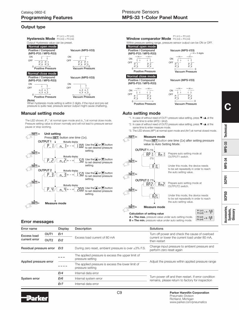
C
Tech
nica
lM
PS-3
3M
PS-3
4SC
P01
SCPS
DAc
cess
orie
s,
Sym
bols
, Gl
ossa
ry
C9 Parker Hannifin CorporationPneumatic DivisionRichland, Michiganwww.parker.com/pneumatics
Catalog 0802-E
Programming FeaturesPressure SensorsMPS-33 1-Color Panel Mount
Hysteresis ModeOutput Hysteresis value can be preset. Within pressure setting range, pressure sensor output can be ON or OFF.
Positive / Compound(MPS-P33 / MPS-R33)
Vacuum (MPS-V33)
Positive / Compound(MPS-P33 / MPS-R33)
Vacuum (MPS-V33)
Positive / Compound(MPS-P33 / MPS-R33)
Vacuum (MPS-V33)
Positive / Compound(MPS-P33 / MPS-R33)
Vacuum (MPS-V33)
Positive Pressure
Positive Pressure
Vacuum PressurePositive Pressure Vacuum Pressure
Vacuum Pressure
Positive Pressure Vacuum Pressure
P1 (n1) > P2 (n2)P3 (n3) > P4 (n4) Window comparator Mode
P1 (n1) < P2 (n2)P3 (n3) < P4 (n4)
Normal open mode
Normal close mode
Normal open mode
Normal close mode
ON
OFFP_2P_4
P_1P_3
P_2P_4
00
00
00
00
P_1P_3 P_2
P_4P_1P_3
ON
OFF
ON
OFFn_2n_4
n_1n_3
n_2n_4
n_1n_3
ON
OFFON
OFF
ON
OFF
(Note)When hysteresis mode setting is within 2 digits, if the input and pre-setpressure is quite near, pressure sensor output might cause chattering.
H H
P_2P_4
P_1P_3
ON
OFF
H H
P_2P_4
P_1P_3
H H
P_2P_4
P_1P_3
ON
OFF
H H
H = 3 digits
Error messages
Error name Display Description Solutions
Excess load current error
OUT1 Er1Excess load current of 80 mA
Turn off power and check the cause of overload current or lower the current load under 80 mA, then restart OUT2 Er2
Residual pressure error Er3 During zero reset, ambient pressure is over ±3% F.S. Change input pressure to ambient pressure and perform zero reset again
Applied pressure error– – – The applied pressure is excess the upper limit of
pressure settingAdjust the pressure within applied pressure range
– – – – The applied pressure is excess the lower limit of pressure setting
System error
Er4 Internal data errorTurn power off and then restart. If error condition remains, please return to factory for inspectionEr6 Internal system error
Er7 Internal data error
Output type
Manual setting mode Auto setting mode
SETSET
SET
SET
SET
SET
Mutually displayOUTPUT 1
OUTPUT 2
Measure mode
The LED shows: (P_* at normal open mode and (n_*) at normal close mode.Pressure setting value is shown normally and will not lead to pressure sensorpause or stop working.
Use the or buttonto set desired pressuresetting.
Use the or buttonto set desired pressuresetting.
Use the or buttonto set desired pressuresetting.
Use the or buttonto set desired pressuresetting.
Press button one time (1x).
1x
1x
1x
1x
1x
Mutually display
Mutually display
Mutually display
Unit settingSET
SET
SET
SET
SET
SET
*1. In case of without need of OUT1 pressure value setting, press + at thesame time to enter (AP2) / (An2).
*2. In case of without need of OUT2 pressure value setting, press + at thesame time to enter measure mode.
*3. The LED shows (AP*) at normal open mode and (An*) at normal closed mode.
(*1)
(*3)
(*2)
(*3)
Prepare auto setting mode atOUTPUT1 switch.
Under this mode, the device needsto be set repeatedly in order to reachthe auto setting value.
Under this mode, the device needsto be set repeatedly in order to reachthe auto setting value.
Prepare auto setting mode atOUTPUT2 switch.
P2 (n2)P4 (n4)
A-B4
= B -
P1 (n1)P3 (n3)
A-B4
= A -Calculation of setting valueA = The max. pressure value under auto setting mode.B = The min. pressure value under auto setting mode.
Measure mode
Measure mode
Press button one time (1x) after setting pressurevalue to Auto Setting Mode.
OUTPUT 1
OUTPUT 2
1x
1x
1x
1x
1x

C10 Parker Hannifin CorporationPneumatic DivisionRichland, Michiganwww.parker.com/pneumatics
C
TechnicalM
PS-33M
PS-34SCP01
SCPSDAccessories,
Symbols,
Glossary
Catalog 0802-E
Features, Ordering InformationPressure SensorsMPS-34 2-Color Panel Mount
Features• Sensor output:
1 NPN or PNP Open collector Transistor output, 30VDC, 125mA with Analog output, 4 to 20mA
• Output response time less than 2.0 milliseconds
• RoHS
• Air and non-corrosive gases
• Sensor face includes icons to show sensor programming status
Internal circuit for open collector and analog output wiring
Sensor pin out with analog outputPin # 1 Brown: 24VDC 2 White: 4 to 20mA 3 Blue: 0VDC 4 Black: PNP Open Collector Output 1
2
1
4
3
Sw
itch
mai
n ci
rcui
t
0V (Blue)
DC 12~24V± 10%
Out 1 (Black)
Load
+V (Brown)
Analog (White)(4-20mA)
PNP Output (Analog (4-20mA)
+
−
Max.80mA
MPS-34 Accessories
Description Part number
Panel mounting bracket Note : Add “H” in suffex of Sensor Only Part Number to include with sensor MPS-ACCH9
Surface mounting bracket Note : Add “K” in suffex of Sensor Only Part Number to include with sensor MPS-ACCK10
Example: MPS-P34N-PCIK, includes sensor MPS-P34N-PCI witth bracket MPS-ACCK10
M8, 4-Pin, 2 meter cable CB-M8-4P-2M-PUR
M8, 4-Pin, 5 meter cable CB-M8-4P-5M-PUR
Most popular.
Red Green Display
MPS-34 Sensor only ordering numbers
Pressure range Electrical output Electrical connection
Part number Part number
1/8 NPSF male 1/8 BSPP male
0-30 inHg (1) PNP with (1) 4-20ma M8, 4 Pin MPS-V34N-PCI MPS-V34G-PCI
0-145 PSI (1) PNP with (1) 4-20ma M8, 4 Pin MPS-P34N-PCI MPS-P34G-PCI
Programming optionsOutputs change N.O. / N.C. 4
Units of measure change 4
Hysteresis mode 4
Window comparator mode 4
Auto teach mode 4
Output response time 4
Lockout option 4Password lockout —Max. value display 4
Min. value display 4
Zero reset 4
Red / Green LED display options 4
Error output mode 4
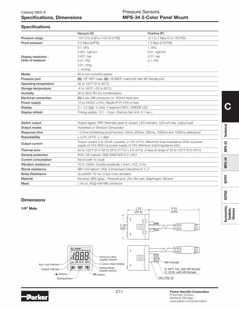
C11 Parker Hannifin CorporationPneumatic DivisionRichland, Michiganwww.parker.com/pneumatics
C
Tech
nica
lM
PS-3
3M
PS-3
4SC
P01
SCPS
DAc
cess
orie
s,
Sym
bols
, Gl
ossa
ry
Catalog 0802-E
Specifications, DimensionsPressure SensorsMPS-34 2-Color Panel Mount
SpecificationsVacuum (V) Positive (P)
Pressure range -101.3 to 0 kPa (-14.5 to 0 PSI) -0.1 to 1 Mpa (0 to 145 PSI)
Proof pressure 0.3 Mpa (44PSI) 1.5 Mpa (218 PSI)
Display resolution , Units of measure
0.1, kPa0.001, kgf/cm2
0.001, bar0.01, PSI0.01, inHg1, mmHg
1, kPa0.01, kgf/cm²0.01, bar0.1, PSI--
Media Air & non-corrosive gases
Pressure port (N) 1/8" NPT male, (G) 1/8 BSPP male both with M5 female port
Operating temperature 32 to 122°F (0 to 50°C)
Storage temperature -4 to 140°F (-20 to 60°C)
Humidity 35 to 85% RH (no condensation)
Electrical connection (C) 4-pin, M8 connector on 150mm lead wire
Power supply 12 to 24VDC ±10%, Ripple (P-P) 10% or less
Display 3 + 1/2 digit, 2 color, 7-segment RED / GREEN LED
Display refresh Timing update : 0.1 ~ 3 sec. (Factory Set Unit: 0.1 sec.)
Switch output Output signal, PNP, Normally open or closed, LED indicator, 125 mA max. output load
Output modes Hysteresis or Window Comparator
Response time ≤ 2.5ms (chattering-proof function: 24ms, 250ms, 500ms, 1000ms and 1500ms selections)
Repeatability ± 0.2% of F.S. ± 1 digit
Output current Output current 4 to 20mA; Linearity ±1.0% of F.S.; Maximum load impedance 300Ω at power supply of 12V; 600Ω at power supply of 12V; Minimum load impedance 50Ω
Thermal error 32 to 122°F (0 to 50°C) 25°C (77°C) + 2% of F.S. or less at range of 32 to 122°F (0 to 50°C)
General protection IP40, CE marked, EMC-EN61000-6-2: 2001
Current consumption 45mA (with no load)
Vibration resistance 10 to 150Hz, Double amplitude 1.5mm, XYZ, 2 hrs.
Shock resistance 980 m/s² (about 10G), 3 times/each directions X, Y, Z
Noise Resistance Vp-p400V, 10 ms, 0.5μs noise simulator
Material Housing: ABS (gray) , Pressure port: Zinc die-cast, Diaphragm: Silicone
Mass 1.45 oz. (45g) with M8 connector
Dimensions
1/8" Male 1.22(25.4)
5.51(140)
1.18(30)
N: NPT 1/8, with M5 femaleG: G1/8, with M5 female
M5 Female
Hex Flat 10
MAX WIN N.C. AUTO
mmHg inHg PSI BAR Kgf kPa
MAX HYS N.O. MANOUT
Setting Button
() Button
Output Indicator
Key Lock IndicatorSetting ModeDisplay Section
() Button
2 Colors, Main Display
Pressure UbnitDisplay Section
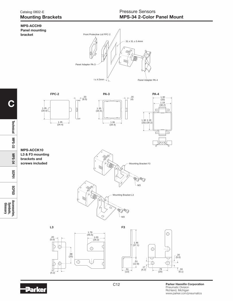
C12 Parker Hannifin CorporationPneumatic DivisionRichland, Michiganwww.parker.com/pneumatics
C
TechnicalM
PS-33M
PS-34SCP01
SCPSDAccessories,
Symbols,
Glossary
Pressure SensorsMPS-34 2-Color Panel Mount
Catalog 0802-E
Mounting Brackets
MPS-ACCH9Panel mounting bracket
1.35(34.4)
1.35(34.4)
.16(4)
FPC-2 PA-3 PA-4 1.30(33)1.19
(30.2)
1.30(33)
1.19 (30.2)
.33(8.5)
1.35(34.4)
1.35(34.4)
Front Protective Lid FPC-2
Panel Adapter PA-4
Panel Adapter PA-3
31 x 31 ± 0.4mm
t ≤ 4.5mm
.17(4.2)
.20(5.0)
.20(5.0)
1.03(26.2)
.79(20)
.51(13)
.17(4.2)
.51(12.9)
1.46(37.1)
.24(6.1)
1.79(45.5)
.98(25)
L3 F3
Mounting Bracket F3
Mounting Bracket L3
M3
M3
MPS-ACCK10L3 & F3 mounting brackets and screws included

C13 Parker Hannifin CorporationPneumatic DivisionRichland, Michiganwww.parker.com/pneumatics
C
Tech
nica
lM
PS-3
3M
PS-3
4SC
P01
SCPS
DAc
cess
orie
s,
Sym
bols
, Gl
ossa
ry
Catalog 0802-E
Programming FeaturesPressure SensorsMPS-34 2-Color Panel Mount
Use the or button to set output type.
Use the or button to set operating mode.
Use the or button to set display color.
Use the or button to set desired pressure unit.
NC ModeNO Mode
AutoManual
2.5ms 24ms 250ms 500ms 1000ms 1500ms
Window ComparatorMode
HysteresisMode
inHg(*1) mmHg(*1)kPa
ON:GREEN
ON:RED
ON / OFF:GREEN
ON / OFF:RED
bar psikgf/cm2
1. Unit setting
2. Display color setting
3. Operating mode setting
Press SET button for more than 3 seconds.SET
4. Output type setting
Use the or button to select auto / manual.
Use the or button to set response time.
5. Response time setting
6. Auto preset setting
7. Measure mode
Note: *1: Only for MPS-V34
1xSET
1xSET
1xSET
1xSET
1xSET
1xSET
SET
SET
UnlockMode
LockMode
Measure mode• Key lock mode can prevent operation mistakes.
Press SET button for less than 5 seconds.Key lock / unlock mode
Use the or button toselect Lock / Unlock Mode.
1x
Key lock / unlock mode
Initial setting mode
Zero point setting / the max. & min. display mode Zero setting:• press the button at the same time until the
“00” is shown. Release the button to end zero setting.
The max. value display mode:• Press button 2 seconds to enter the max.
value mode, pressure sensor will detect the max. value and keep max. value displayed.
• Press button 2 seconds to return to measure mode display.
The min. value display mode:• Press button 2 seconds to enter the min.
value mode, pressure sensor will detect the min. value and keep min. value displayed.
• Press button 2 seconds to return to measure mode display.
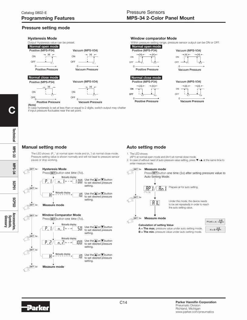
C14 Parker Hannifin CorporationPneumatic DivisionRichland, Michiganwww.parker.com/pneumatics
C
TechnicalM
PS-33M
PS-34SCP01
SCPSDAccessories,
Symbols,
Glossary
Catalog 0802-E
Programming FeaturesPressure SensorsMPS-34 2-Color Panel Mount
Pressure setting mode
H H
H H
H H
H
H
H
H
H H
Positive Pressure Vacuum Pressure Positive Pressure Vacuum Pressure
Hysteresis ModeOutput Hysteresis value can be preset. Within pressure setting range, pressure sensor output can be ON or OFF.
Positive (MPS-P34)
Positive (MPS-P34)
Positive (MPS-P34)
Positive (MPS-P34)
Vacuum (MPS-V34) Vacuum (MPS-V34)
Window comparator Mode
Normal open mode Normal open mode
Vacuum (MPS-V34) Vacuum (MPS-V34)
Positive Pressure Vacuum Pressure Positive Pressure Vacuum Pressure
Normal close mode Normal close mode
0 0
0 0 0 0
0 0
ON
OFF
ON
OFF
ON
OFF
ON
OFF
(Note)In case hysteresis is set at less than or equal to 2 digits, switch output may chatterif input pressure fluctuates near the set point.
Calculation of setting ValueA = The max. pressure value under auto setting mode.B = The min. pressure value under auto setting mode.
Measure mode
1. The LED shows: (AP1) at normal open mode and (An1) at normal close mode.2. In case of without need of auto pressure value setting, press + at the same time to
enter measure mode.
A-B4H = B
P1 (n1)A-B4= A -
Prepare air for auto setting.
Under this mode, the device needsto be set repeatedly in order to reachthe auto setting value.
1xSET
1xSET
Measure modePress SET button one time (1x) after setting pressure value toAuto Setting Mode.
1xSET
Manual setting mode Auto setting modeThe LED shows: (P_* at normal open mode and (n_*) at normal close mode.Pressure setting value is shown normally and will not lead to pressure sensorpause or stop working.
Press SET button one time (1x).
Press SET button one time (1x).
Mutually display
Mutually display
Mutually display
Mutually display
Mutually display
Measure mode
Measure mode
Hysteresis Mode
Window Comparator Mode
Use the or buttonto set desired pressuresetting.
Use the or buttonto set desired pressuresetting.
Use the or buttonto set desired pressuresetting.
Use the or buttonto set desired pressuresetting.
Use the or buttonto set desired pressuresetting.
1xSET
1xSET
1xSET
1xSET
1xSET
1xSET
1xSET
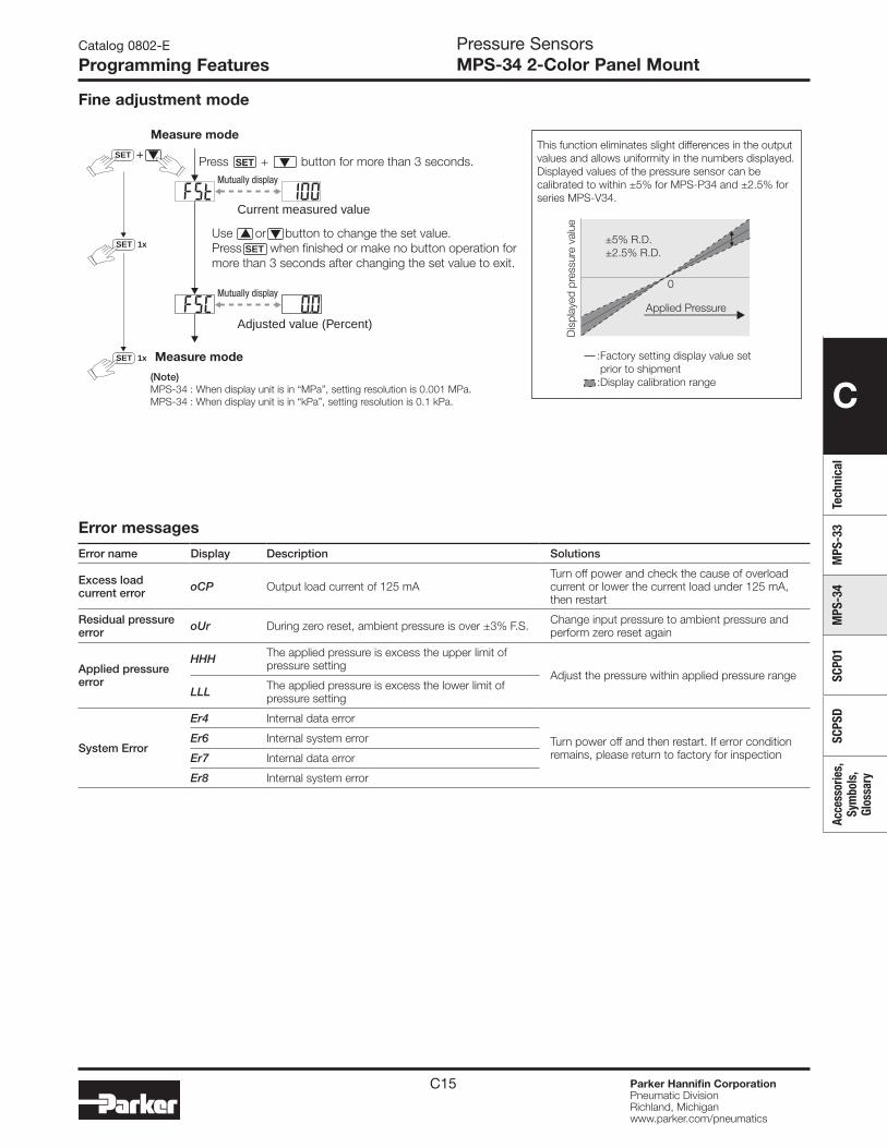
C15 Parker Hannifin CorporationPneumatic DivisionRichland, Michiganwww.parker.com/pneumatics
C
Tech
nica
lM
PS-3
3M
PS-3
4SC
P01
SCPS
DAc
cess
orie
s,
Sym
bols
, Gl
ossa
ry
Error messages
Error name Display Description Solutions
Excess load current error oCP Output load current of 125 mA
Turn off power and check the cause of overload current or lower the current load under 125 mA, then restart
Residual pressure error oUr During zero reset, ambient pressure is over ±3% F.S. Change input pressure to ambient pressure and
perform zero reset again
Applied pressure error
HHH The applied pressure is excess the upper limit of pressure setting
Adjust the pressure within applied pressure rangeLLL The applied pressure is excess the lower limit of
pressure setting
System Error
Er4 Internal data error
Turn power off and then restart. If error condition remains, please return to factory for inspection
Er6 Internal system error
Er7 Internal data error
Er8 Internal system error
Fine adjustment mode
Measure mode
Measure mode
Press SET + button for more than 3 seconds.
Current measured value
Adjusted value (Percent)
Use or button to change the set value.Press SET when finished or make no button operation formore than 3 seconds after changing the set value to exit.
SET
Mutually display
Mutually display
(Note)MPS-34 : When display unit is in “MPa”, setting resolution is 0.001 MPa.MPS-34 : When display unit is in “kPa”, setting resolution is 0.1 kPa.
+This function eliminates slight differences in the outputvalues and allows uniformity in the numbers displayed.Displayed values of the pressure sensor can becalibrated to within ±5% for MPS-P34 and ±2.5% forseries MPS-V34.
Dis
play
ed p
ress
ure
valu
e
:Factory setting display value set prior to shipment:Display calibration range
Applied Pressure
0
±5% R.D.±2.5% R.D.
1xSET
1xSET
Catalog 0802-E
Programming FeaturesPressure SensorsMPS-34 2-Color Panel Mount
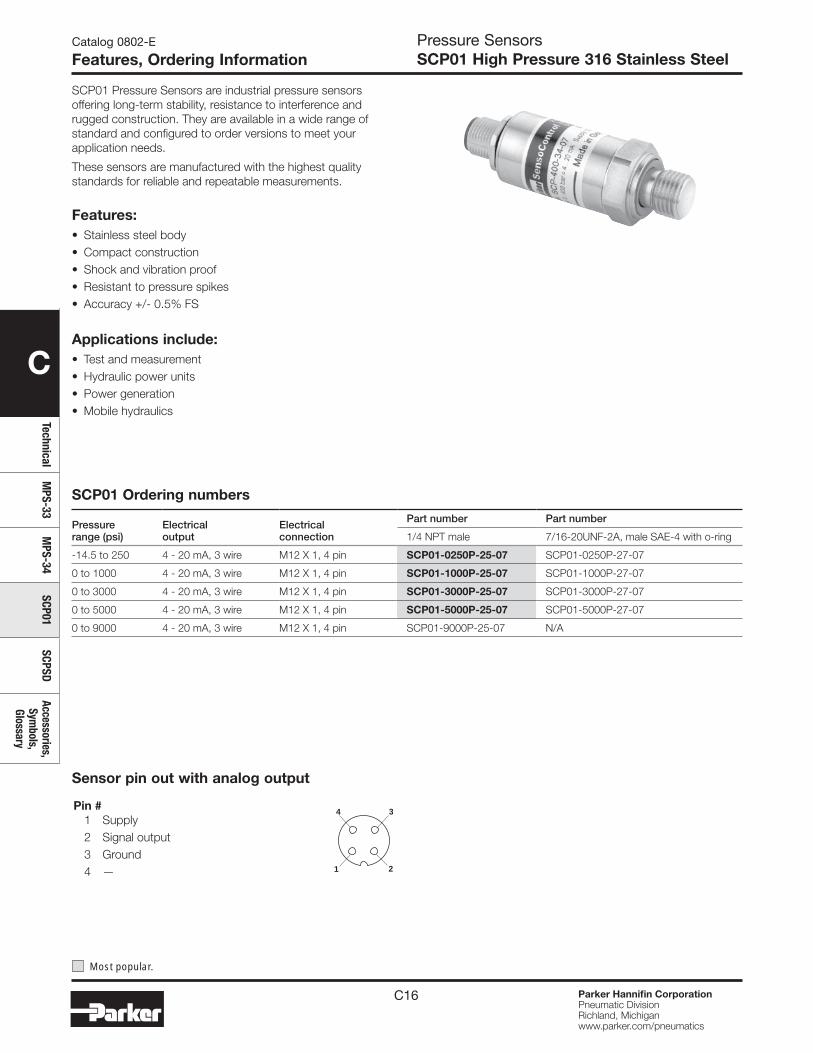
C16 Parker Hannifin CorporationPneumatic DivisionRichland, Michiganwww.parker.com/pneumatics
C
TechnicalM
PS-33M
PS-34SCP01
SCPSDAccessories,
Symbols,
Glossary
Pressure SensorsSCP01 High Pressure 316 Stainless Steel
Catalog 0802-E
Features, Ordering Information
SCP01 Pressure Sensors are industrial pressure sensors offering long-term stability, resistance to interference and rugged construction. They are available in a wide range of standard and configured to order versions to meet your application needs.
These sensors are manufactured with the highest quality standards for reliable and repeatable measurements.
Features:• Stainless steel body• Compact construction• Shock and vibration proof• Resistant to pressure spikes• Accuracy +/- 0.5% FS
Applications include:• Test and measurement• Hydraulic power units• Power generation• Mobile hydraulics
Sensor pin out with analog output
Pin # 1 Supply 2 Signal output 3 Ground 4 — 21
4 3
Most popular.
SCP01 Ordering numbers
Pressure range (psi)
Electrical output
Electrical connection
Part number Part number
1/4 NPT male 7/16-20UNF-2A, male SAE-4 with o-ring
-14.5 to 250 4 - 20 mA, 3 wire M12 X 1, 4 pin SCP01-0250P-25-07 SCP01-0250P-27-07
0 to 1000 4 - 20 mA, 3 wire M12 X 1, 4 pin SCP01-1000P-25-07 SCP01-1000P-27-07
0 to 3000 4 - 20 mA, 3 wire M12 X 1, 4 pin SCP01-3000P-25-07 SCP01-3000P-27-07
0 to 5000 4 - 20 mA, 3 wire M12 X 1, 4 pin SCP01-5000P-25-07 SCP01-5000P-27-07
0 to 9000 4 - 20 mA, 3 wire M12 X 1, 4 pin SCP01-9000P-25-07 N/A
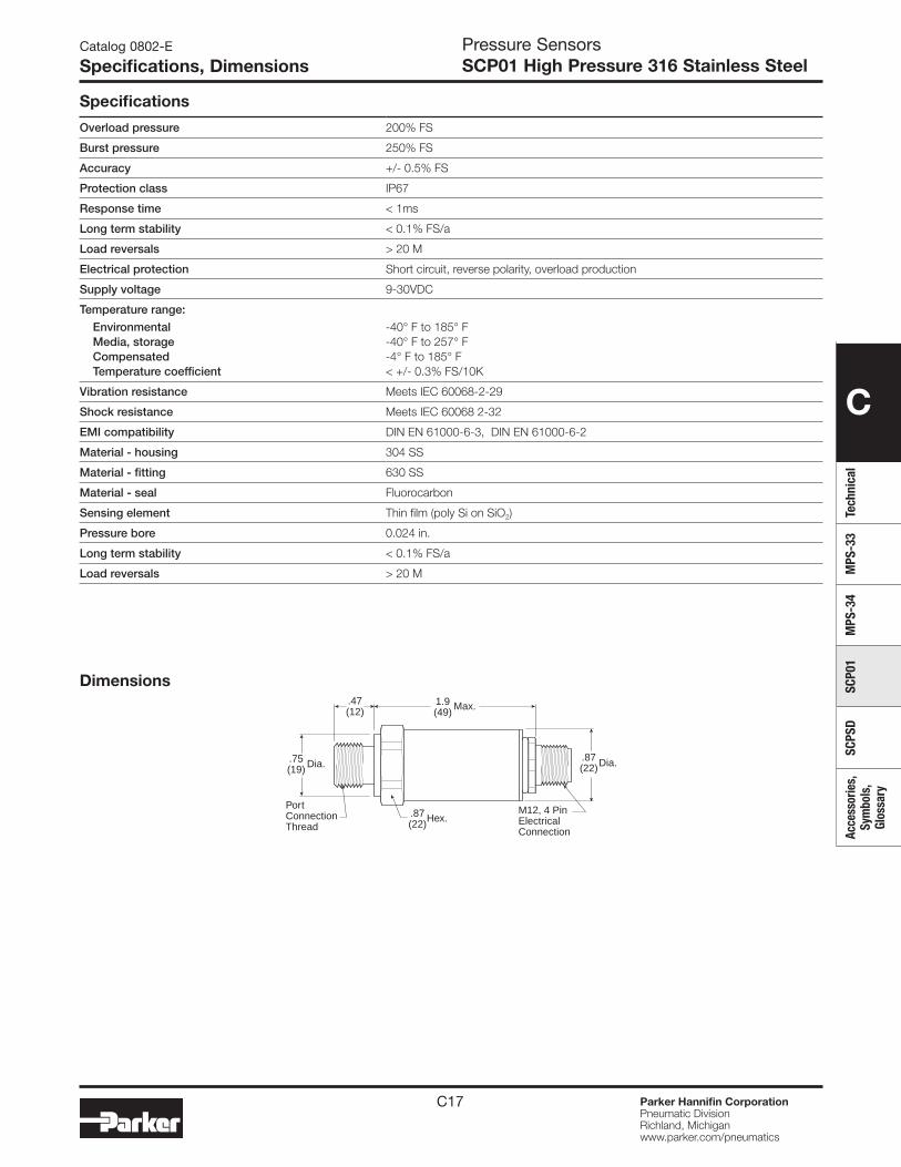
C17 Parker Hannifin CorporationPneumatic DivisionRichland, Michiganwww.parker.com/pneumatics
C
Tech
nica
lM
PS-3
3M
PS-3
4SC
P01
SCPS
DAc
cess
orie
s,
Sym
bols
, Gl
ossa
ry
Dimensions.47(12)
1.9(49)
PortConnectionThread
M12, 4 PinElectricalConnection
.87(22)Hex.
.75(19) Dia.
.87(22)Dia.
Max.
Pressure SensorsSCP01 High Pressure 316 Stainless Steel
Catalog 0802-E
Specifications, Dimensions
Specifications
Overload pressure 200% FS
Burst pressure 250% FS
Accuracy +/- 0.5% FS
Protection class IP67
Response time < 1ms
Long term stability < 0.1% FS/a
Load reversals > 20 M
Electrical protection Short circuit, reverse polarity, overload production
Supply voltage 9-30VDC
Temperature range:
Environmental -40° F to 185° FMedia, storage -40° F to 257° F Compensated -4° F to 185° FTemperature coefficient < +/- 0.3% FS/10K
Vibration resistance Meets IEC 60068-2-29
Shock resistance Meets IEC 60068 2-32
EMI compatibility DIN EN 61000-6-3, DIN EN 61000-6-2
Material - housing 304 SS
Material - fitting 630 SS
Material - seal Fluorocarbon
Sensing element Thin film (poly Si on SiO2)
Pressure bore 0.024 in.
Long term stability < 0.1% FS/a
Load reversals > 20 M
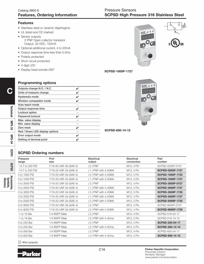
C18 Parker Hannifin CorporationPneumatic DivisionRichland, Michiganwww.parker.com/pneumatics
C
TechnicalM
PS-33M
PS-34SCP01
SCPSDAccessories,
Symbols,
Glossary
Pressure SensorsSCPSD High Pressure 316 Stainless Steel
Catalog 0802-E
Features, Ordering Information
Features• Stainless steel or ceramic diaphragms• UL listed and CE marked• Sensor outputs
2 PNP Open collector transistor Output, 30 VDC, 100mA
• Optional additional current, 4 to 20mA • Output response time less than 5.0ms• Polarity protected• Short circuit protected• 4 digit LED• Display head swivels 290°
SCPSD-600-14-15
SCPSD-1000P-1727
SCPSD Ordering numbers
Pressure range
Port size
Electrical output
Electrical connection
Part number
-14.7 to 250 PSI 7/16-20 UNF-2b (SAE-4) ( 2 ) PNP M12, 4 Pin SCPSD-0250P-0727
-14.7 to 250 PSI 7/16-20 UNF-2b (SAE-4) ( 1 ) PNP with 4-20MA M12, 4 Pin SCPSD-0250P-1727
0 to 1000 PSI 7/16-20 UNF-2b (SAE-4) ( 2 ) PNP with 4-20MA M12, 5 Pin SCPSD-1000P-1725
0 to 1000 PSI 7/16-20 UNF-2b (SAE-4) ( 1 ) PNP with 4-20MA M12, 4 Pin SCPSD-1000P-1727
0 to 3000 PSI 7/16-20 UNF-2b (SAE-4) ( 2 ) PNP M12, 4 Pin SCPSD-3000P-0727
0 to 3000 PSI 7/16-20 UNF-2b (SAE-4) ( 1 ) PNP with 4-20MA M12, 4 Pin SCPSD-3000P-1727
0 to 3000 PSI 7/16-20 UNF-2b (SAE-4) ( 2 ) PNP with 4-20MA M12, 5 Pin SCPSD-3000P-1725
0 to 5000 PSI 7/16-20 UNF-2b (SAE-4) ( 1 ) PNP with 4-20MA M12, 4 Pin SCPSD-5000P-1727
0 to 5000 PSI 7/16-20 UNF-2b (SAE-4) ( 2 ) PNP with 4-20MA M12, 5 Pin SCPSD-5000P-1725
0 to 9000 PSI 7/16-20 UNF-2b (SAE-4) ( 2 ) PNP M12, 4 Pin SCPSD-9000P-0727
0 to 9000 PSI 7/16-20 UNF-2b (SAE-4) ( 2 ) PNP with 4-20MA M12, 4 Pin SCPSD-9000P-1725
-1 to 16 Bar 1/4 BSPP Male ( 2 ) PNP M12, 4 Pin SCPSD-016-04-17
-1 to 16 Bar 1/4 BSPP Male ( 2 ) PNP with 4-20ma M12, 5 Pin SCPSD-016-14-15
0 to 250 Bar 1/4 BSPP Male ( 2 ) PNP M12, 4 Pin SCPSD-250-04-17
0 to 250 Bar 1/4 BSPP Male ( 2 ) PNP with 4-20ma M12, 5 Pin SCPSD-250-14-15
0 to 600 Bar 1/4 BSPP Male ( 2 ) PNP M12, 4 Pin SCPSD-600-04-17
0 to 600 Bar 1/4 BSPP Male ( 2 ) PNP with 4-20ma M12, 5 Pin SCPSD-600-14-15
Most popular.
Programming optionsOutputs change N.O. / N.C. 4
Units of measure change 4
Hysteresis mode 4
Window comparator mode 4Auto teach mode —Output response time 4Lockout option —Password lockout 4Max. value display —Min. value display —Zero reset 4Red / Green LED display options —Error output mode 4
Setting of decimal point 4

C19 Parker Hannifin CorporationPneumatic DivisionRichland, Michiganwww.parker.com/pneumatics
C
Tech
nica
lM
PS-3
3M
PS-3
4SC
P01
SCPS
DAc
cess
orie
s,
Sym
bols
, Gl
ossa
ry
Pressure SensorsSCPSD High Pressure 316 Stainless Steel
Catalog 0802-E
Specifications
SpecificationsPressure code 0250 016 1000 3000 5000 9000 250 600Measure range PSI, (bar ) -14.7 to 250 (-1 to 16) 0 to 1000 0 to 3000 0 to 5000 0 to 9000 (0 to 250) (0 to 600)Overload pressure PSI, (bar ) 725 (40) 2900 7250 11600 21750 (500) (1200)Burst pressure PSI, (bar ) 725 (50) 11600 17400 24650 31900 (1200) (2200)Sensing element Ceramic Stainless Steel
Parts in contact with media
Stainless steel 1.4404Stainless steel 1.4404, 1.4542, NBR*
Ceramic AL203, NBR*
*FPDM, EPDM special requestUnits of measure PSI, bar, MPASwitch cycles >100 millionOutput response time < 10msPower supply 15 to 30VDC, Class 2 power supplyShort circuit protection Yes, 2.4 amp / open collector outputReverse polarity protection YesOverload protection YesCurrent consumption < 100mAOutput circuit 2 PNP (Sourcing) open collector transistorAnalog output 0/4…20mA, Programmable, freely scaleableOutput functions Hysteresis, Window comparatorSwitching voltage -1.5VDCMaximum current output 1A with 2 open collector outputs, .5A per outputAccuracy ± 0.5% F.S. Typ., ± 1% Max.Repeatability ± 0.25% F.S.Display accuracy ± 0.5% F.S. Typ., ± 1 DigitThermal error max. ±0.03% F.S. at -4 to 185°F (-20 to 85°C)Material Pressure Die-cast zinc Z 410: Surface-finishingDisplay material PolyesterGeneral protection IP 67, EN60529, UL, CE Marked, EMC-EN50082-2 Class B, EN 50081-2Temperature range of media -4 to 185°F (-20 to 85°C)Ambiant temperature range -4 to 185°F (-20 to 85°C)Storage temperature -40 to 212°F (-40 to 100°C)Display 4-Digit, 7-Segment LED, Red, 9mm heightTightening torque 35NmVibration resistance 20G, 10 to 500Hz, IEC60068-2-6Shock resistance 50 G, XYZ, 11ms, IEC60068-2-29Mass 10.6 oz. (300g)
Internal circuit
BlackBlack
WhiteWhite
Gray
BlueBlue
M12, 5-Pin, (2) PNP Outputs with 4 to 20mA AnalogM12, 4-Pin, (2) PNP Outputs
M12, 4-Pin, (1) PNP Output with 4 to 20mA Analog
1
1
4
2
5
1
4
2
33
2
4
5
3
(Sensor Socket)
Brown Brown
1 2
4 3
(Sensor Socket)
0V / Gnd0V / Gnd
S1
S2
S1
S2
+Ub (24VDC)+Ub (24VDC)
Black
White
Blue
1
4
2
3
(Sensor Socket)
Brown
1 2
4 3 0V / Gnd
S1
Analog Out
+Ub (24VDC)
Analog Out
Note: M12, 5-Pin Female Cable Connector will fit on both M12, 4-Pin and 5-Pin Male Sensor Connector.
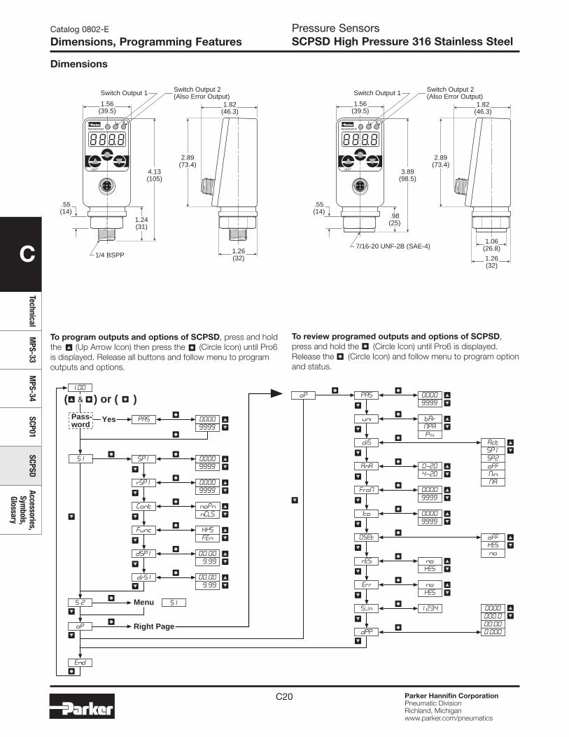
C20 Parker Hannifin CorporationPneumatic DivisionRichland, Michiganwww.parker.com/pneumatics
C
TechnicalM
PS-33M
PS-34SCP01
SCPSDAccessories,
Symbols,
Glossary
Pressure SensorsSCPSD High Pressure 316 Stainless Steel
Dimensions
UNIT
SensoControl
1.56(39.5)
1.82(46.3)
3.89(98.5)
2.89(73.4)
.55(14)
7/16-20 UNF-2B (SAE-4)
.98(25)
I II
Switch Output 2(Also Error Output)Switch Output 1
1.06(26.8)
1.26(32)
UNIT
SensoControl
1.56(39.5)
1.82(46.3)
4.13(105)
2.89(73.4)
.55(14)
1/4 BSPP
1.24(31)
I II
Switch Output 2(Also Error Output)Switch Output 1
1.26(32)
Right Page
Menu
YesPass-word
( ) or ( )
To program outputs and options of SCPSD, press and hold the (Up Arrow Icon) then press the (Circle Icon) until Pro6 is displayed. Release all buttons and follow menu to program outputs and options.
To review programed outputs and options of SCPSD, press and hold the (Circle Icon) until Pro6 is displayed. Release the (Circle Icon) and follow menu to program option and status.
Catalog 0802-E
Dimensions, Programming Features
C21 Parker Hannifin CorporationPneumatic DivisionRichland, Michiganwww.parker.com/pneumatics
C
Tech
nica
lM
PS-3
3M
PS-3
4SC
P01
SCPS
DAc
cess
orie
s,
Sym
bols
, Gl
ossa
ry
Pressure SensorsSCPSD High Pressure 316 Stainless Steel
Catalog 0802-E
Programming Features
Parameters shown in digital displayTo program switch outputs in menu S1 (S1 = output 1) or S2 (S2 = output 2), press and hold, then press . Pro6 will be displayed for 2 seconds.
PRS This is dedicated to a password. Entry into the programming mode can be secured only when the correct figures have been entered
Menu for programming the switch outputs:
S1 S1 = Switch output 1
S2 S2 = Switch output 2 (Menu is not active if S2 is being used as an error output)
Switching point (SP): upper limiting value / pressure, at which the switch output changes its status.
SP1 SP1 = Switch output 1; input as pressure value (e.g. 400 bar)
SP2 SP2 = Switch output 2; input as pressure value (e.g. 430 bar)
Reverse switching point (rSP): lower limiting value/ pressure at which switch output changes its status.
rSP1 rSP1 = Reverse switching point (rSP1) of switch output 1; input as pressure value (e.g. 390 bar)
rSP2 rSP2 = Reverse switching point (rSP2) of switch output 2; input as pressure value (e.g. 420 bar) The reverse switching point is always smaller than its respective switching point. If the reverse switching point is set higher than the switching point, the reverse switching point will be set automatically 0.5% of the instrument nominal pressure below the switching point. The warning sign Att (attention) will appear, which can be cleared with Enter.
cont Switch output as noPn = closer nCLS = opener
Func Selection of switching functions: HySt = Hysteresis function FEn = Window fu nction
Delay times; input from 0 to 9.99 s.
dSPI dSPI= delay time switching point output 1
drSL drSI = delay time reverse switching point output 1
dSP2 dSP2 = delay time switching point output 2
drS2 drS2 =delay time reverse switching point output 2
SUn Indication of Software Version
dPP Setting of the decimal point. (The maximum number of decimal points depends on the nominal pressure of the SCPSD instrument) 0000 = no decimal point000.0 = 1 decimal point00.00 = 2 decimal points0.000 = 3 decimal points
End End of programming mode
0Set Zero adjustment: The actual pressure will be stored as a new zero point. For safety reasons this is limited to the range ± 5% of the nominal instrument pressure. Application example: a system with a continuous residual pressure, but which should be displayed as 0 bar. OFF = factory calibrationyES = undertake zeroing adjustment nowno= go back to the menu and do not make any new zeroing adjustments. After a zeroing adjustment, a pressure of up to 20 bar can be displayed as 0 on a 400 bar SCPSD. Before working on a system, it must be ensured that there is no pressure in it.
rES Clearing the minimum and maximum value memoryyES = yes, clear memory nowno = no, do not clear memory
Err Programming switch output 2 as an error output yES = yesno = no
Switch Output 2 can be used optionally as an error output to display pressure switch function errors. As an error output it is normally closed, and in case of errors (Err1,Err2,Err3) it is open. At the same time LED II lights up. The display and the output remain active until the error is cleared.
!
Settings for options programoP Options program
PA5 Password input0000 = no password Example password 1234 = 1234
uni Setting of units:bAr = bar NPA= MPa PSi= PSI
diS Display: Value which will be shown on the digital display in run mode. Act = Actual system pressureNin = Minimum system pressure; (pressure troughs)NA = Maximum system pressure; (pressure peaks)SPl = Switch point 1SP2 = Switch point 2OFF = off indication
AnA Setting of analog output (see point 4)0-20= 0-20 mA 4-20 = 4-20 mA
FroN Calibration of starting value (0 or 4 mA) for the analog output.Settable from 0 to nominal instrument pressure. Example for AnA = 4-20:0000 = at 0 bar the analog output yields 4mA.The starting value is always smaller than the end value. If the starting value is set greater than the end value, then the starting value will be automatically set 5% of the nominal instrument pressure below that of the end value. The warning sign Att1 will appear, which can be cleared with the Enter sign.
to Calibration of end value (20mA) for the analog output.Settable from 0 up to nominal instrument pressure. 0010 = at 10 bar the analogue output yields 20 mA.
!

C22 Parker Hannifin CorporationPneumatic DivisionRichland, Michiganwww.parker.com/pneumatics
C
TechnicalM
PS-33M
PS-34SCP01
SCPSDAccessories,
Symbols,
Glossary
Pressure SensorsSCPSD High Pressure 316 Stainless Steel
Catalog 0802-E
Caution, Accessories
Electrical test unit (M12, 5-Pin)SCSN-450-PSD
SCPSD programming kitSCSD-PRG-KIT
Optical Interface Device that allows read / write and storing of SCPSD configuration data. Kit includes optical interface device, electrical test unit with PC cable (RS232 connector) and software.
Optical Interface Device
SCPSD
InstallationMechanical: CAUTION: Install and de-install the SCPSD only when there is no pressure present.
Attach the SCPSD to the appropriate process connection. Installation should be undertaken only with a 22mm, across flats spanner. Ensure that the digital display is placed in the best viewing position by using the rotational housing adjustment. Turn the SCPSD manually to the required position. Maximum 290°.
Excessive turning beyond the easily detectable end stop will lead to damage.
• The housing can be attached:• with self-tapping screws into two blind holes at the back of
the housing• with the mounting plate provided• with cable ties
Electrical: CAUTION: The SCPSD may be installed only by a qualified electrician in accordance with the respective national and international regulations.
Protect the SCPSD from electromagnetic influences and over-voltages.
Optional installation tips which are shown by experience to reduce the influence of interference:
• Use shorter cables• Avoid short distances between connecting leads and power
consuming devices and interference generating electrical and electronic equipment
• Use free running diodes
!
!
Avoid static and dynamic over-pressures which exceed the specified overload pressure. Even when the overload pressure is exceeded only for a short time the SCPSD may be damaged. Parker SensoControl diagnostic systems are recommended for measuring pressure peaks exactly.
If there is a danger of excessively high pressure peaks, it is recommended to:
• use an SCPSD with a higher nominal instrument pressure (analog output can then be correspondingly matched)
• install a standard throttling device upstream from the SCPSD
Display Description
AttThe set value is lower than the other respective parameters. When Enter is activated, the smaller value is matched up.
Err1 System Error (Internal)
Err2 Nominal instrument pressure range was exceeded by 10%. Please check system pressure.
Err3Nominal instrument pressure range has been exceeded Error in analog electronics. Please check system pressure.
Error messages
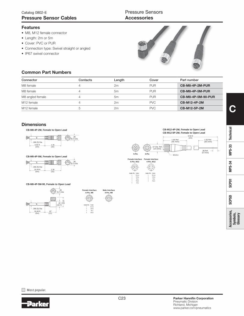
C23 Parker Hannifin CorporationPneumatic DivisionRichland, Michiganwww.parker.com/pneumatics
C
Tech
nica
lM
PS-3
3M
PS-3
4SC
P01
SCPS
DAc
cess
orie
s,
Sym
bols
, Gl
ossa
ry
Pressure SensorsAccessories
Catalog 0802-E
Pressure Sensor Cables
.38 Ref.(9.7mm)
.57 Dia. Ref.(14.5mm)
M12x1
1.84 Ref.(46.7mm)
1.50 Ref.(38.1mm)
6.56 ft(2m)
CB-M12-5P-2M, Female to Open Lead CB-M12-4P-2M, Female to Open Lead
4-Pin5-Pin
Female Interface4-Pin, M12
3 42 1
Cable Pin Color
1 Brown
2 White
3 Blue
4 Black
Female Interface5-Pin, M12
3 45
2 1
Cable Pin Color
1 Brown
2 White
3 Blue
4 Black
5 Gray
Common Part Numbers
Connector Contacts Length Cover Part number
M8 female 4 2m PUR CB-M8-4P-2M-PUR
M8 female 4 5m PUR CB-M8-4P-5M-PUR
M8 angled female 4 5m PUR CB-M8-4P-5M-90-PUR
M12 female 4 2m PVC CB-M12-4P-2M
M12 female 5 2m PVC CB-M12-5P-2M
Features• M8, M12 female connector • Length: 2m or 5m • Cover: PVC or PUR • Connection type: Swivel straight or angled• IP67 swivel connector
.196 (5) Dia
6.56 ft(2m)
1.26(32)
CB-M8-4P-2M, Female to Open Lead
CB-M8-4P-5M, Female to Open Lead
CB-M8-4P-5M-90, Female to Open Lead
.196 (5) Dia
.38(9,7) Dia
16.40 ft(5m)
1.26(32)
.38(9,7) Dia
.196 (5) Dia
.38(9,7) Dia
16.40 ft(5m)
.87(22)
.42(10,7)
.75(19)
Female Interface4-Pin, M8
2 4
1 3
Cable Pin Color
1 Brown
2 White
3 Blue
4 Black
Male Interface4-Pin, M8
24
13
Dimensions
Most popular.
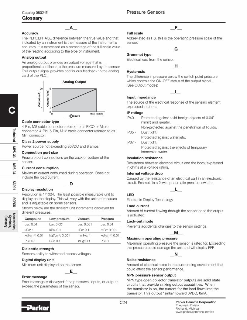
C24 Parker Hannifin CorporationPneumatic DivisionRichland, Michiganwww.parker.com/pneumatics
C
TechnicalM
PS-33M
PS-34SCP01
SCPSDAccessories,
Symbols,
Glossary
Pressure SensorsCatalog 0802-E
Glossary
__A__AccuracyThe PERCENTAGE difference between the true value and that indicated by an instrument is the measure of the instrument’s accuracy. It is expressed as a percentage of the full-scale value of the reading according to the type of instrument.
Analog outputAn analog output provides an output voltage that is proportional and linear to the pressure measured by the sensor. This output signal provides continuous feedback to the analog card of the PLC.
__C__Cable connector type4-Pin, M8 cable connector referred to as PICO or Micro connector. 4-Pin, 5-Pin, M12 cable connector referred to as Mini connector.
Class 2 power supplyPower source not exceeding 30VDC and 8 amps.
Connection port sizePressure port connections on the back or bottom of the sensor.
Current consumptionMaximum current consumed during operation. Does not include the load current.
__D__Display resolutionResolution is 1/1024. The least possible measurable unit to display on the display. This will vary with the units of measure and is adjustable on some sensors.Shown below are the different unit increments displayed for different pressures.
Compound Low pressure Vacuum Pressure
bar: 0.01 bar: 0.001 bar: 0.001 bar: 0.01
kPa: 1 kPa: 0.1 kPa: 0.1 mPa: 0.001
kgf/cm2: 0.01 kgf/cm2: 0.001 mmHg: 1 kgf/cm2: 0.01
PSI: 0.1 PSI: 0.1 inHg: 0.1 PSI: 1
Dielectric strengthSensors ability to withstand excess voltages.
Digital display unitMinimum unit displayed on the sensor.
__E__Error messageError message is displayed if the pressures, inputs, or outputs exceed the parameters of the sensor.
__F__Full scaleAbbreviated as F.S. this is the operating pressure scale of the sensor.
__G__Grommet typeElectrical lead from the sensor.
__H__HysteresisThe difference in pressure below the switch point pressure which controls the ON-OFF status of the output signal. (See Output modes)
__I__Input impedanceThe source of the electrical response of the sensing element expressed in ohms.
IP ratingsIP40 - Protected against solid foreign objects of 0.04" (1mm) and greater. Non-protected against the penetration of liquids.IP65 - Dust tight. Protected against water jets.IP67 - Dust tight. Protected against the effects of temporary immersion water.
Insulation resistanceResistance between electrical circuit and the body, expressed in ohms at a voltage rating.
Internal voltage dropCaused by the resistance of an electrical part in an electronic circuit. Example is a 2-wire pneumatic pressure switch.
__L__LEDElectronic Display Technology
Load currentAmount of current flowing through the sensor once the output is activated.
Lock-out modePrevents accidental changes to the sensor settings.
__M__Maximum operating pressureMaximum operating pressure the sensor is rated for. Exceeding this pressure could damage the unit and will display FFF.
__N__Noise resistanceAmount of electrical noise in the surrounding environment that could affect the sensor performance.
NPN pressure sensor outputNPN type open collector transistor outputs are solid state circuits that provide sinking output capabilities. When the transistor is on, the current for the load flows into the transistor. This output “sinks” toward 0VDC, 0mA.
5
00 Max. Rating
1
Pressure
Ou
tpu
t (V
olt
s)
20
4
Ou
tpu
t (m
A)
Analog Output
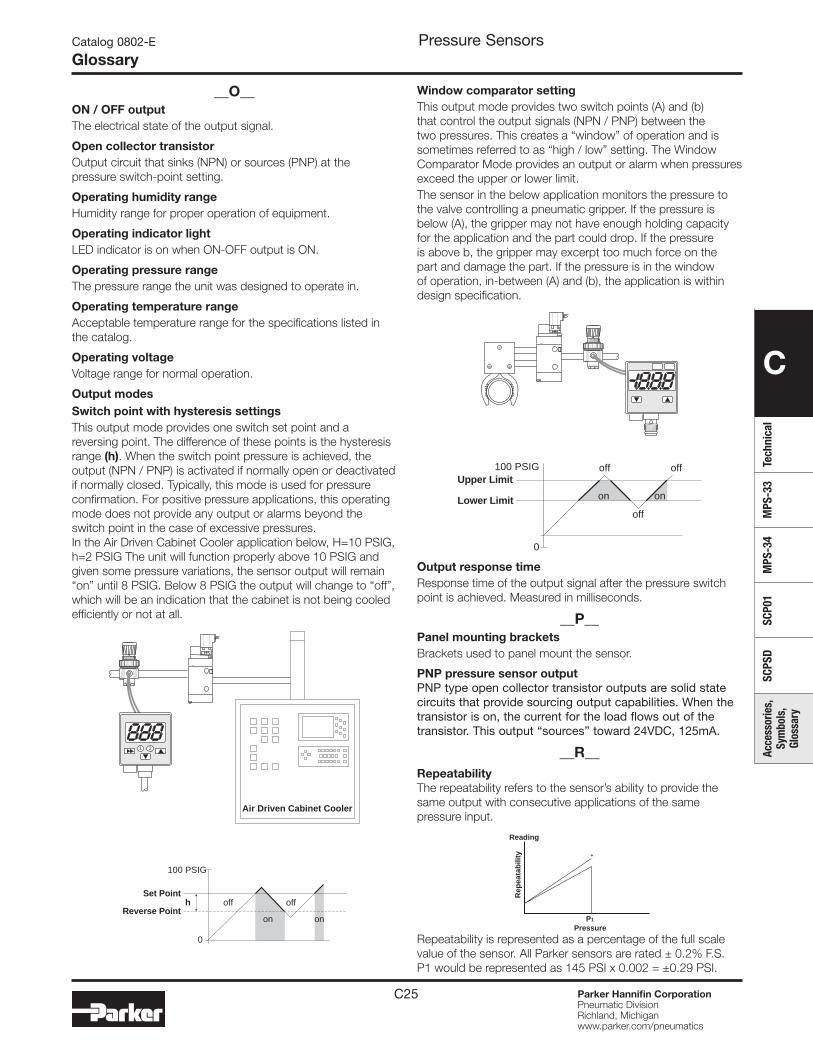
C25 Parker Hannifin CorporationPneumatic DivisionRichland, Michiganwww.parker.com/pneumatics
C
Tech
nica
lM
PS-3
3M
PS-3
4SC
P01
SCPS
DAc
cess
orie
s,
Sym
bols
, Gl
ossa
ry
Window comparator settingThis output mode provides two switch points (A) and (b) that control the output signals (NPN / PNP) between the two pressures. This creates a “window” of operation and is sometimes referred to as “high / low” setting. The Window Comparator Mode provides an output or alarm when pressures exceed the upper or lower limit.The sensor in the below application monitors the pressure to the valve controlling a pneumatic gripper. If the pressure is below (A), the gripper may not have enough holding capacity for the application and the part could drop. If the pressure is above b, the gripper may excerpt too much force on the part and damage the part. If the pressure is in the window of operation, in-between (A) and (b), the application is within design specification.
Output response timeResponse time of the output signal after the pressure switch point is achieved. Measured in milliseconds.
__P__Panel mounting bracketsBrackets used to panel mount the sensor.
__O__ON / OFF outputThe electrical state of the output signal.
Open collector transistorOutput circuit that sinks (NPN) or sources (PNP) at the pressure switch-point setting.
Operating humidity rangeHumidity range for proper operation of equipment.
Operating indicator lightLED indicator is on when ON-OFF output is ON.
Operating pressure rangeThe pressure range the unit was designed to operate in.
Operating temperature rangeAcceptable temperature range for the specifications listed in the catalog.
Operating voltageVoltage range for normal operation.
Output modesSwitch point with hysteresis settingsThis output mode provides one switch set point and a reversing point. The difference of these points is the hysteresis range (h). When the switch point pressure is achieved, the output (NPN / PNP) is activated if normally open or deactivated if normally closed. Typically, this mode is used for pressure confirmation. For positive pressure applications, this operating mode does not provide any output or alarms beyond the switch point in the case of excessive pressures. In the Air Driven Cabinet Cooler application below, H=10 PSIG, h=2 PSIG The unit will function properly above 10 PSIG and given some pressure variations, the sensor output will remain “on” until 8 PSIG. Below 8 PSIG the output will change to “off”, which will be an indication that the cabinet is not being cooled efficiently or not at all.
Pressure SensorsCatalog 0802-E
Glossary
Lower Limit
Upper Limit
off
off off100 PSIG
0
on on
PNP pressure sensor outputPNP type open collector transistor outputs are solid state circuits that provide sourcing output capabilities. When the transistor is on, the current for the load flows out of the transistor. This output “sources” toward 24VDC, 125mA.
__R__RepeatabilityThe repeatability refers to the sensor’s ability to provide the same output with consecutive applications of the same pressure input.
Repeatability is represented as a percentage of the full scale value of the sensor. All Parker sensors are rated ± 0.2% F.S. P1 would be represented as 145 PSI x 0.002 = ±0.29 PSI.
hSet Point
Reverse Pointoff off
0
100 PSIG
on on
21
Air Driven Cabinet Cooler
Rep
eata
bili
ty
PressureP1
+
Reading
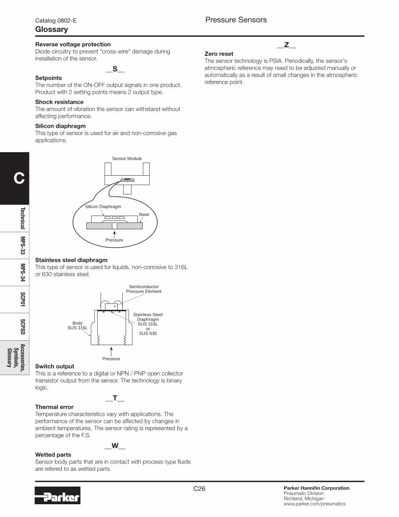
C26 Parker Hannifin CorporationPneumatic DivisionRichland, Michiganwww.parker.com/pneumatics
C
TechnicalM
PS-33M
PS-34SCP01
SCPSDAccessories,
Symbols,
Glossary
Pressure SensorsCatalog 0802-E
Glossary
Silicon Diaphragm
Sensor Module
Pressure
Base
SemiconductorPressure Element
BodySUS 316L
Pressure
Stainless SteelDiaphragmSUS 316L
orSUS 630
Reverse voltage protectionDiode circuitry to prevent "cross-wire" damage during installation of the sensor.
__S__SetpointsThe number of the ON-OFF output signals in one product. Product with 2 setting points means 2 output type.
Shock resistanceThe amount of vibration the sensor can withstand without affecting performance.
Silicon diaphragmThis type of sensor is used for air and non-corrosive gas applications.
Stainless steel diaphragmThis type of sensor is used for liquids, non-corrosive to 316L or 630 stainless steel.
Switch outputThis is a reference to a digital or NPN / PNP open collector transistor output from the sensor. The technology is binary logic.
__T__Thermal errorTemperature characteristics vary with applications. The performance of the sensor can be affected by changes in ambient temperatures. The sensor rating is represented by a percentage of the F.S.
__W__Wetted partsSensor body parts that are in contact with process-type fluids are refered to as wetted parts.
__Z__Zero resetThe sensor technology is PSIA. Periodically, the sensor's atmospheric reference may need to be adjusted manually or automatically as a result of small changes in the atmospheric reference point.
D1 Parker Hannifin CorporationPneumatic DivisionRichland, Michiganwww.parker.com/pneumatics
D
Safe
ty G
uide
, Of
fer
of S
ale
Safety Guide For Selecting And Using Pneumatic Division Products And Related Accessories
WARNING:FAILURE OR IMPROPER SELECTION OR IMPROPER USE OF PNEUMATIC DIVISION PRODUCTS, ASSEMBLIES OR RELATED ITEMS (“PRODUCTS”) CAN CAUSE DEATH, PERSONAL INJURY, AND PROPERTY DAMAGE. POSSIBLE CONSEQUENCES OF FAILURE OR IMPROPER SELECTION OR IMPROPER USE OF THESE PRODUCTS INCLUDE BUT ARE NOT LIMITED TO:• Unintended or mistimed cycling or motion of machine members or failure to cycle• Work pieces or component parts being thrown off at high speeds.• Failure of a device to function properly for example, failure to clamp or unclamp an associated item or device.• Explosion• Suddenly moving or falling objects.• Release of toxic or otherwise injurious liquids or gasses.Before selecting or using any of these Products, it is important that you read and follow the instructions below.
!
Pneumatic ProductsWarnings
Catalog 0802-6
Safety Guide
1. GENERAL INSTRUCTIONS 1.1. Scope: This safety guide is designed to cover general guidelines on the installation, use, and maintenance of Pneumatic Division
Valves, FRLs (Filters, Pressure Regulators, and Lubricators), Vacuum products and related accessory components. 1.2. Fail-Safe: Valves, FRLs, Vacuum products and their related components can and do fail without warning for many reasons. Design all
systems and equipment in a fail-safe mode, so that failure of associated valves, FRLs or Vacuum products will not endanger persons or property.
1.3 Relevant International Standards: For a good guide to the application of a broad spectrum of pneumatic fluid power devices see: ISO 4414:1998, Pneumatic Fluid Power – General Rules Relating to Systems. See www.iso.org for ordering information.
1.4. Distribution: Provide a copy of this safety guide to each person that is responsible for selection, installation, or use of Valves, FRLs or Vacuum products. Do not select, or use Parker valves, FRLs or vacuum products without thoroughly reading and understanding this safety guide as well as the specific Parker publications for the products considered or selected.
1.5. User Responsibility: Due to the wide variety of operating conditions and applications for valves, FRLs, and vacuum products Parker and its distributors do not represent or warrant that any particular valve, FRL or vacuum product is suitable for any specific end use system. This safety guide does not analyze all technical parameters that must be considered in selecting a product. The user, through its own analysis and testing, is solely responsible for: • Making the final selection of the appropriate valve, FRL, Vacuum component, or accessory.
• Assuring that all user’s performance, endurance, maintenance, safety, and warning requirements are met and that the application presents no health or safety hazards.
• Complying with all existing warning labels and / or providing all appropriate health and safety warnings on the equipment on which the valves, FRLs or Vacuum products are used; and,
• Assuring compliance with all applicable government and industry standards. 1.6. Safety Devices: Safety devices should not be removed, or defeated. 1.7. Warning Labels: Warning labels should not be removed, painted over or otherwise obscured. 1.8. Additional Questions: Call the appropriate Parker technical service department if you have any questions or require any additional
information. See the Parker publication for the product being considered or used, or call 1-800-CPARKER, or go to www.parker.com, for telephone numbers of the appropriate technical service department.
2. PRODUCT SELECTION INSTRUCTIONS 2.1. Flow Rate: The flow rate requirements of a system are frequently the primary consideration when designing any pneumatic system.
System components need to be able to provide adequate flow and pressure for the desired application. 2.2. Pressure Rating: Never exceed the rated pressure of a product. Consult product labeling, Pneumatic Division catalogs or the
instruction sheets supplied for maximum pressure ratings. 2.3. Temperature Rating: Never exceed the temperature rating of a product. Excessive heat can shorten the life expectancy of a product
and result in complete product failure. 2.4. Environment: Many environmental conditions can affect the integrity and suitability of a product for a given application. Pneumatic
Division products are designed for use in general purpose industrial applications. If these products are to be used in unusual circumstances such as direct sunlight and/or corrosive or caustic environments, such use can shorten the useful life and lead to premature failure of a product.
2.5. Lubrication and Compressor Carryover: Some modern synthetic oils can and will attack nitrile seals. If there is any possibility of synthetic oils or greases migrating into the pneumatic components check for compatibility with the seal materials used. Consult the factory or product literature for materials of construction.
2.6. Polycarbonate Bowls and Sight Glasses: To avoid potential polycarbonate bowl failures: • Do not locate polycarbonate bowls or sight glasses in areas where they could be subject to direct sunlight, impact blow, or temperatures outside of the rated range.
• Do not expose or clean polycarbonate bowls with detergents, chlorinated hydro-carbons, keytones, esters or certain alcohols. • Do not use polycarbonate bowls or sight glasses in air systems where compressors are lubricated with fire resistant fluids such as
phosphate ester and di-ester lubricants.
D2 Parker Hannifin CorporationPneumatic DivisionRichland, Michiganwww.parker.com/pneumatics
D
Safety Guide, Offer of Sale
2.7. Chemical Compatibility: For more information on plastic component chemical compatibility see Pneumatic Division technical bulletins Tec-3, Tec-4, and Tec-5
2.8. Product Rupture: Product rupture can cause death, serious personal injury, and property damage. • Do not connect pressure regulators or other Pneumatic Division products to bottled gas cylinders.
• Do not exceed the maximum primary pressure rating of any pressure regulator or any system component. • Consult product labeling or product literature for pressure rating limitations.3. PRODUCT ASSEMBLY AND INSTALLATION INSTRUCTIONS 3.1. Component Inspection: Prior to assembly or installation a careful examination of the valves, FRLs or vacuum products must be
performed. All components must be checked for correct style, size, and catalog number. DO NOT use any component that displays any signs of nonconformance.
3.2. Installation Instructions: Parker published Installation Instructions must be followed for installation of Parker valves, FRLs and vacuum components. These instructions are provided with every Parker valve or FRL sold, or by calling 1-800-CPARKER, or at www.parker.com.
3.3. Air Supply: The air supply or control medium supplied to Valves, FRLs and Vacuum components must be moisture-free if ambient temperature can drop below freezing
4. VALVE AND FRL MAINTENANCE AND REPLACEMENT INSTRUCTIONS 4.1. Maintenance: Even with proper selection and installation, valve, FRL and vacuum products service life may be significantly reduced
without a continuing maintenance program. The severity of the application, risk potential from a component failure, and experience with any known failures in the application or in similar applications should determine the frequency of inspections and the servicing or replacement of Pneumatic Division products so that products are replaced before any failure occurs. A maintenance program must be established and followed by the user and, at minimum, must include instructions 4.2 through 4.10.
4.2. Installation and Service Instructions: Before attempting to service or replace any worn or damaged parts consult the appropriate Service Bulletin for the valve or FRL in question for the appropriate practices to service the unit in question. These Service and Installation Instructions are provided with every Parker valve and FRL sold, or are available by calling 1-800-CPARKER, or by accessing the Parker web site at www.parker.com.
4.3. Lockout / Tagout Procedures: Be sure to follow all required lockout and tagout procedures when servicing equipment. For more information see: OSHA Standard – 29 CFR, Part 1910.147, Appendix A, The Control of Hazardous Energy – (Lockout / Tagout)
4.4. Visual Inspection: Any of the following conditions requires immediate system shut down and replacement of worn or damaged components: • Air leakage: Look and listen to see if there are any signs of visual damage to any of the components in the system. Leakage is an indication of worn or damaged components.
• Damaged or degraded components: Look to see if there are any visible signs of wear or component degradation. • Kinked, crushed, or damaged hoses. Kinked hoses can result in restricted air flow and lead to unpredictable system behavior. • Any observed improper system or component function: Immediately shut down the system and correct malfunction. • Excessive dirt build-up: Dirt and clutter can mask potentially hazardous situations. Caution: Leak detection solutions should be rinsed off after use. 4.5. Routine Maintenance Issues:
• Remove excessive dirt, grime and clutter from work areas. • Make sure all required guards and shields are in place. 4.6. Functional Test: Before initiating automatic operation, operate the system manually to make sure all required functions operate
properly and safely. 4.7. Service or Replacement Intervals: It is the user’s responsibility to establish appropriate service intervals. Valves, FRLs and vacuum
products contain components that age, harden, wear, and otherwise deteriorate over time. Environmental conditions can significantly accelerate this process. Valves, FRLs and vacuum components need to be serviced or replaced on routine intervals. Service intervals need to be established based on: • Previous performance experiences.
• Government and / or industrial standards. • When failures could result in unacceptable down time, equipment damage or personal injury risk. 4.8. Servicing or Replacing of any Worn or Damaged Parts: To avoid unpredictable system behavior that can cause death, personal
injury and property damage: • Follow all government, state and local safety and servicing practices prior to service including but not limited to all OSHA Lockout Tagout procedures (OSHA Standard – 29 CFR, Part 1910.147, Appendix A, The Control of Hazardous Energy – Lockout / Tagout).
• Disconnect electrical supply (when necessary) before installation, servicing, or conversion. • Disconnect air supply and depressurize all air lines connected to system and Pneumatic Division products before installation, service,
or conversion. • Installation, servicing, and / or conversion of these products must be performed by knowledgeable personnel who understand how
pneumatic products are to be applied. • After installation, servicing, or conversions air and electrical supplies (when necessary) should be connected and the product tested
for proper function and leakage. If audible leakage is present, or if the product does not operate properly, do not put product or system into use.
• Warnings and specifications on the product should not be covered or painted over. If masking is not possible, contact your local representative for replacement labels.
4.9. Putting Serviced System Back into Operation: Follow the guidelines above and all relevant Installation and Maintenance Instructions supplied with the valve FRL or vacuum component to insure proper function of the system.
Pneumatic ProductsWarnings
Catalog 0802-6
Safety Guide

D3 Parker Hannifin CorporationPneumatic DivisionRichland, Michiganwww.parker.com/pneumatics
D
Safe
ty G
uide
, Of
fer
of S
ale
Pneumatic ProductsCatalog 0802-6
Offer of Sale
1. TermsandConditions. Seller’s willingness to offer Products, or accept an order for Products, to or from Buyer is expressly conditioned on Buyer’s assent to these Terms and Conditions and to the terms and conditions found on-line at www.parker.com/saleterms/. Seller objects to any contrary or additional term or condition of Buyer’s order or any other document issued by Buyer.2. Price Adjustments; Payments. Prices stated on the reverse side or preceding pages of this document are valid for 30 days. After 30 days, Seller may change prices to reflect any increase in its costs resulting from state, federal or local legislation, price increases from its suppliers, or any change in the rate, charge, or classification of any carrier. The prices stated on the reverse or preceding pages of this document do not include any sales, use, or other taxes unless so stated specifically. Unless otherwise specified by Seller, all prices are F.O.B. Seller's facility, and payment is due 30 days from the date of invoice. After 30 days, Buyer shall pay interest on any unpaid invoices at the rate of 1.5% per month or the maximum allowable rate under applicable law.3. DeliveryDates;TitleandRisk;Shipment. All delivery dates are approximate and Seller shall not be responsible for any damages resulting from any delay. Regardless of the manner of shipment, title to any products and risk of loss or damage shall pass to Buyer upon tender to the carrier at Seller's facility (i.e., when it’s on the truck, it’s yours). Unless otherwise stated, Seller may exercise its judgment in choosing the carrier and means of delivery. No deferment of shipment at Buyers' request beyond the respective dates indicated will be made except on terms that will indemnify, defend and hold Seller harmless against all loss and additional expense. Buyer shall be responsible for any additional shipping charges incurred by Seller due to Buyer’s changes in shipping, product specifications or in accordance with Section 13, herein.4. Warranty. Seller warrants that the Products sold hereunder shall be free from defects in material or workmanship for a period of twelve months from the date of delivery to Buyer or 2,000 hours of normal use, whichever occurs first. This warranty is made only to Buyer and does not extend to anyone to whom Products are sold after purchased from Seller. The prices charged for Seller's products are based upon the exclusive limited warranty stated above, and upon the following disclaimer: DISCLAIMER OF WARRANTY:THISWARRANTYCOMPRISESTHESOLEANDENTIREWARRANTYPERTAININGTOPRODUCTSPROVIDEDHEREUNDER.SELLERDISCLAIMSALLOTHERWARRANTIES,EXPRESSANDIMPLIED,INCLUDINGMERCHANTABILITYANDFITNESSFORAPARTICULARPURPOSE.5. Claims; Commencement of Actions. Buyer shall promptly inspect all Products upon delivery. No claims for shortages will be allowed unless reported to the Seller within 10 days of delivery. No other claims against Seller will be allowed unless asserted in writing within 60 days after delivery or, in the case of an alleged breach of warranty, within 30 days after the date within the warranty period on which the defect is or should have been discovered by Buyer. Any action based upon breach of this agreement or upon any other claim arising out of this sale (other than an action by Seller for any amount due to Seller from Buyer) must be commenced within thirteen months from the date of tender of delivery by Seller or, for a cause of action based upon an alleged breach of warranty, within thirteen months from the date within the warranty period on which the defect is or should have been discovered by Buyer.6. LIMITATIONOFLIABILITY.UPON NOTIFICATION, SELLER WILL, AT ITS OPTION, REPAIR OR REPLACE A DEFECTIVE PRODUCT, OR REFUND THE PURCHASE PRICE. INNOEVENTSHALLSELLERBELIABLETOBUYERFORANYSPECIAL,INDIRECT,INCIDENTALORCONSEQUENTIALDAMAGESARISINGOUTOF,ORASTHERESULTOF,THESALE,DELIVERY,NON-DELIVERY,SERVICING,USEORLOSSOFUSEOFTHEPRODUCTSORANYPARTTHEREOF,ORFORANYCHARGES OR EXPENSES OF ANY NATURE INCURRED WITHOUT SELLER'SWRITTEN CONSENT, EVEN IF SELLER HAS BEEN NEGLIGENT, WHETHER INCONTRACT,TORTOROTHERLEGALTHEORY.INNOEVENTSHALLSELLER'SLIABILITYUNDERANYCLAIMMADEBYBUYEREXCEEDTHEPURCHASEPRICEOFTHEPRODUCTS.7. Contingencies. Seller shall not be liable for any default or delay in performance if caused by circumstances beyond the reasonable control of Seller.8. User Responsibility. The user, through its own analysis and testing, is solely responsible for making the final selection of the system and Product and assuring that all performance, endurance, maintenance, safety and warning requirements of the application are met. The user must analyze all aspects of the application and follow applicable industry standards and Product information. If Seller provides Product or system options, the user is responsible for determining that such data and specifications are suitable and sufficient for all applications and reasonably foreseeable uses of the Products or systems.9. Loss to Buyer's Property. Any designs, tools, patterns, materials, drawings, confidential information or equipment furnished by Buyer or any other items which become Buyer's property, may be considered obsolete and may be destroyed by Seller after two consecutive years have elapsed without Buyer placing an order for the items which are manufactured using such property. Seller shall not be responsible for any loss or damage to such property while it is in Seller's possession or control.10. SpecialTooling. A tooling charge may be imposed for any special tooling, including without limitation, dies, fixtures, molds and patterns, acquired to manufacture Products. Such special tooling shall be and remain Seller's property notwithstanding payment of any charges by Buyer. In no event will Buyer acquire any interest in apparatus belonging to Seller which is utilized in the manufacture of the Products, even if such apparatus has been specially converted or adapted for such manufacture and notwithstanding any charges paid by Buyer. Unless otherwise agreed, Seller shall have the right to alter, discard or otherwise dispose of any special tooling or other property in its sole discretion at any time.
TheitemsdescribedinthisdocumentandotherdocumentsanddescriptionsprovidedbyParkerHannifinCorporation,itssubsidiariesanditsauthorizeddistributors(“Seller”)areherebyofferedforsaleatpricestobeestablishedbySeller.Thisofferanditsacceptancebyanycustomer(“Buyer”)shallbegovernedbyallofthefollowingTermsandConditions.Buyer’sorderforanyitemdescribedinitsdocument,whencommunicatedtoSellerverbally,orinwriting,shallconstituteacceptanceofthisoffer.Allgoodsorworkdescribedwillbereferredtoas“Products”.
11. Buyer's Obligation; Rights of Seller. To secure payment of all sums due or otherwise, Seller shall retain a security interest in the goods delivered and this agreement shall be deemed a Security Agreement under the Uniform Commercial Code. Buyer authorizes Seller as its attorney to execute and file on Buyer's behalf all documents Seller deems necessary to perfect its security interest. Seller shall have a security interest in, and lien upon, any property of Buyer in Seller's possession as security for the payment of any amounts owed to Seller by Buyer.12. Improper use and Indemnity. Buyer shall indemnify, defend, and hold Seller harmless from any claim, liability, damages, lawsuits, and costs (including attorney fees), whether for personal injury, property damage, patent, trademark or copyright infringement or any other claim, brought by or incurred by Buyer, Buyer’s employees, or any other person, arising out of: (a) improper selection, improper application or other misuse of Products purchased by Buyer from Seller; (b) any act or omission, negligent or otherwise, of Buyer; (c) Seller’s use of patterns, plans, drawings, or specifications furnished by Buyer to manufacture Product; or (d) Buyer’s failure to comply with these terms and conditions. Seller shall not indemnify Buyer under any circumstance except as otherwise provided.13. Cancellations and Changes. Orders shall not be subject to cancellation or change by Buyer for any reason, except with Seller's written consent and upon terms that will indemnify, defend and hold Seller harmless against all direct, incidental and consequential loss or damage. Seller may change product features, specifications, designs and availability with notice to Buyer.14. LimitationonAssignment. Buyer may not assign its rights or obligations under this agreement without the prior written consent of Seller.15. Entire Agreement. This agreement contains the entire agreement between the Buyer and Seller and constitutes the final, complete and exclusive expression of the terms of the agreement. All prior or contemporaneous written or oral agreements or negotiations with respect to the subject matter are herein merged.16. Waiver and Severability. Failure to enforce any provision of this agreement will not waive that provision nor will any such failure prejudice Seller’s right to enforce that provision in the future. Invalidation of any provision of this agreement by legislation or other rule of law shall not invalidate any other provision herein. The remaining provisions of this agreement will remain in full force and effect.17. Termination. This agreement may be terminated by Seller for any reason and at any time by giving Buyer thirty (30) days written notice of termination. In addition, Seller may by written notice immediately terminate this agreement for the following: (a) Buyer commits a breach of any provision of this agreement (b) the appointment of a trustee, receiver or custodian for all or any part of Buyer’s property (b) the filing of a petition for relief in bankruptcy of the other Party on its own behalf, or by a third party (c) an assignment for the benefit of creditors, or (d) the dissolution or liquidation of the Buyer.18. GoverningLaw. This agreement and the sale and delivery of all Products hereunder shall be deemed to have taken place in and shall be governed and construed in accordance with the laws of the State of Ohio, as applicable to contracts executed and wholly performed therein and without regard to conflicts of laws principles. Buyer irrevocably agrees and consents to the exclusive jurisdiction and venue of the courts of Cuyahoga County, Ohio with respect to any dispute, controversy or claim arising out of or relating to this agreement. Disputes between the parties shall not be settled by arbitration unless, after a dispute has arisen, both parties expressly agree in writing to arbitrate the dispute.19. IndemnityforInfringementofIntellectualPropertyRights. Seller shall have no liability for infringement of any patents, trademarks, copyrights, trade dress, trade secrets or similar rights except as provided in this Section. Seller will defend and indemnify Buyer against allegations of infringement of U.S. patents, U.S. trademarks, copyrights, trade dress and trade secrets (“Intellectual Property Rights”). Seller will defend at its expense and will pay the cost of any settlement or damages awarded in an action brought against Buyer based on an allegation that a Product sold pursuant to this Agreement infringes the Intellectual Property Rights of a third party. Seller's obligation to defend and indemnify Buyer is contingent on Buyer notifying Seller within ten (10) days after Buyer becomes aware of such allegations of infringement, and Seller having sole control over the defense of any allegations or actions including all negotiations for settlement or compromise. If a Product is subject to a claim that it infringes the Intellectual Property Rights of a third party, Seller may, at its sole expense and option, procure for Buyer the right to continue using the Product, replace or modify the Product so as to make it noninfringing, or offer to accept return of the Product and return the purchase price less a reasonable allowance for depreciation. Notwithstanding the foregoing, Seller shall have no liability for claims of infringement based on information provided by Buyer, or directed to Products delivered hereunder for which the designs are specified in whole or part by Buyer, or infringements resulting from the modification, combination or use in a system of any Product sold hereunder. The foregoing provisions of this Section shall constitute Seller's sole and exclusive liability and Buyer's sole and exclusive remedy for infringement of Intellectual Property Rights.20. Taxes. Unless otherwise indicated, all prices and charges are exclusive of excise, sales, use, property, occupational or like taxes which may be imposed by any taxing authority upon the manufacture, sale or delivery of Products.21. Equal Opportunity Clause. For the performance of government contracts and where dollar value of the Products exceed $10,000, the equal employment opportunity clauses in Executive Order 11246, VEVRAA, and 41 C.F.R. §§ 60-1.4(a), 60-741.5(a), and 60-250.4, are hereby incorporated.

Catalog 0802-E 6/2011
Applications EngineeringPhone: 877 321 4PDN Option #2E-mail: [email protected] SupportPhone: 877 321 4PDN Option #1E-mail: [email protected] site: www.parker.com/pneumatics
Parker Hannifin CorporationPneumatic Division8676 E. M89P.O. Box 901Richland, MI 49083 USATel: 269 629 5000Fax: 269 629 5385