vacuum circuit breaker - sequin, c.a. - control y ... vcb(e).pdf · 33 ≤0.04 ≤0.04 ≤0.06...
TRANSCRIPT

CESI, KERI, CCC, ISO 9001, ISO 14001
Vacuum Circuit Breaker
2
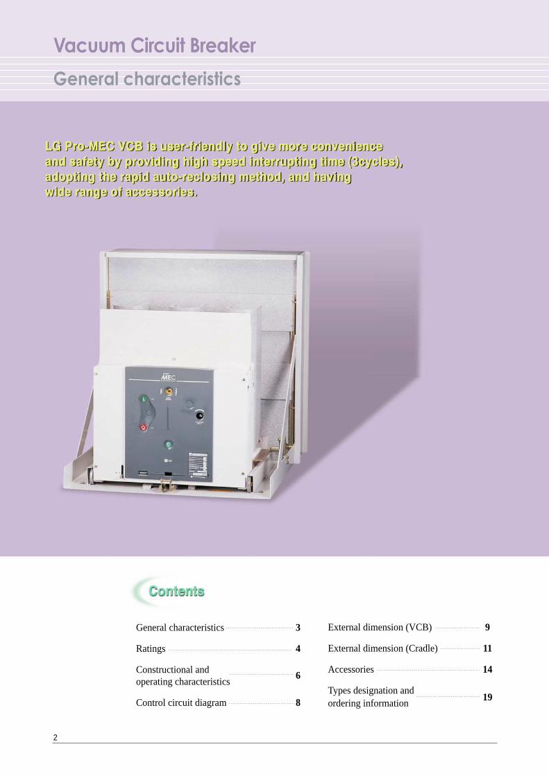
Vacuum Circuit Breaker
General characteristics
General characteristics 3
Ratings 4
Constructional and 6operating characteristics
Control circuit diagram 8
External dimension (VCB) 9
External dimension (Cradle) 11
Accessories 14
Types designation and 19
ordering information
3
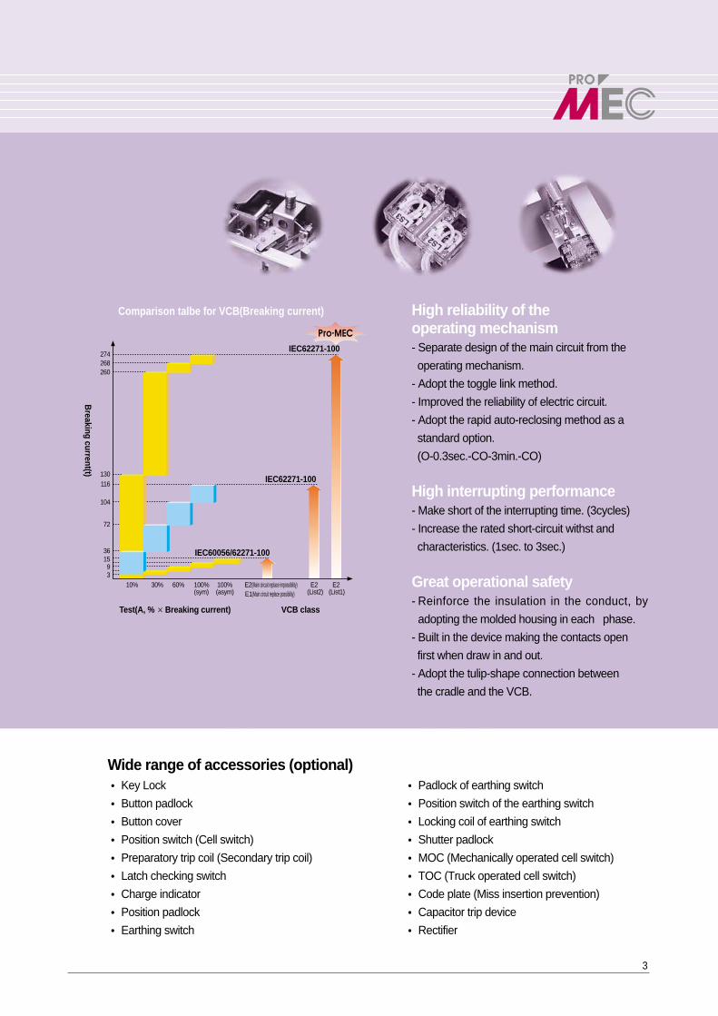
Comparison talbe for VCB(Breaking current)
Test(A, %×Breaking current) VCB class
IEC60056/62271-100
IEC62271-100
IEC62271-100
Breaking current(t)
E2(Main circuit replace impossibility)E1(Main circuit replace possibility)
310% 30% 60% 100% 100%
(List2)(sym) (asym) (List1)E2 E2
91536
72
104
116130
260268274
Pro-MEC
Wide range of accessories (optional) � Key Lock � Padlock of earthing switch
� Button padlock � Position switch of the earthing switch
� Button cover � Locking coil of earthing switch
� Position switch (Cell switch) � Shutter padlock
� Preparatory trip coil (Secondary trip coil) � MOC (Mechanically operated cell switch)
� Latch checking switch � TOC (Truck operated cell switch)
� Charge indicator � Code plate (Miss insertion prevention)
� Position padlock � Capacitor trip device
� Earthing switch � Rectifier
High reliability of the operating mechanism- Separate design of the main circuit from the
operating mechanism.
- Adopt the toggle link method.
- Improved the reliability of electric circuit.
- Adopt the rapid auto-reclosing method as a
standard option.
(O-0.3sec.-CO-3min.-CO)
High interrupting performance- Make short of the interrupting time. (3cycles)
- Increase the rated short-circuit withst and
characteristics. (1sec. to 3sec.)
Great operational safety- Reinforce the insulation in the conduct, by
adopting the molded housing in each phase.
- Built in the device making the contacts open
first when draw in and out.
- Adopt the tulip-shape connection between
the cradle and the VCB.
24 24
630 630
1250 1250
2000
50/60 50/60
12.5 25
520 1000
12.5 25
32.5 65
3 3
≤ 0.04 ≤ 0.04
≤ 0.06 ≤ 0.06
50 50
125 125
O-0.3s-CO-3min-CO O-0.3s-CO-3min-CO
M2 M2
E2 List1 E2 List1
C2 C2
20000 20000
30000 30000
20000 20000
30000 30000
4a4b, 10a10b 4a4b, 10a10b
Releasing, Fixed - Releasing, Fixed -
Releasing, Clip Hermetic, Tulip Releasing, Clip Hermetic, Tulip
Releasing, Clip Hermetic, Tulip Releasing, Clip Hermetic, Tulip
Releasing, Tulip Hermetic, Tulip Releasing, Tulip Hermetic, Tulip
- Hermetic, Tulip - Hermetic, Tulip
145 145 145 145
145 145 145 145
155 187 155187(630/1250A)
218 (2000A)
80 80 80 80
82 82 82 82
110 120 110 120
IEC 62271-100 IEC 62271-100
� �
Vacuum Circuit Breaker
Ratings
4
Rated voltage (kV)
Rated current (A)
Rated frequency (Hz)
Rated breaking current (kA)
Rated breaking capacity (MVA)
Rated short-time current (kA/3sec)
Rated closing current (kA)
Rated breaking time (Cycle)
Rated opening time (sec)
No-load closing time (sec)
Withstand voltagePower frequency (kV/1.2 X 50㎲㎲)
Impulse (kV/1.2 X 50㎲㎲)
Standard test duty
Mechanical
Class Electrical
Charge current breaking Note 1)
Mechanical(Time)
Lifetime(Time)
Electrical(Time)
(Time)
Auxiliary switch
Fixed type
Installing method Draw-out type
(kg)
VCB(kg)
(kg)Weight
(kg)
Cradle (kg)
(kg)
Applied standard
Test laboratory KERI
Without maintenance
Maintenance
Without maintenance
Maintenance
E-type
F-type
G-type Note 2)
M-type
E-type
F-type
G-type
E-type
F-type
G-type
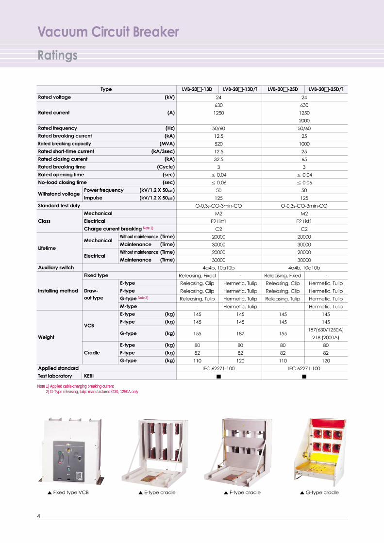
▲ Fixed type VCB ▲ E-type cradle ▲ F-type cradle ▲ G-type cradle
LVB-20��-13D LVB-20��-13D/T LVB-20��-25D LVB-20��-25D/T
Note 1) Applied cable-charging breaking current2) G-Type releasing, tulip: manufactured G30, 1250A only
Type

5
VCB
ON
OFF
a contact s/w
ON
OFF
b contact s/w
OFF
ON
Motor
Closing Coil (C)The coil operated only when the power is appliedcontinuously over 45ms. It has built-in electrically anti-pumping circuit.
��Position of the Aux.contact switch
Note 1)Range of the normal operating voltage : 85~110%2) DC 24V is the underdeveloped rating.
Shunt coil (TC)When the VCB is 'ON' position, even though the controlpower of a shunt coil is 'OFF', the VCB maintains the 'ON'position.
Note 1)Range of the normal operating voltage : 70~110%2) DC 24V is the underdeveloped rating.
Auxiliary switch
Charging indicator ofthe closing coil
Indicating the condition of the closing spring.
Position indicator of the main contactsIndicating the 'Close' or the 'Open' of the main contacts.Close position : ��ON�� Open position : ��OFF��
Indicator of the contact wearIndicator of the contact wear of the Vacuum Interrupter. When it indicate '3', the user need to replace the VI.
CounterMechanically counts the switching of the VCB by 5digit analog type counter (Standard option)
Charged Discharged
Close position Open position
When the closing spring is charged, the control power of motor is turned off by the built-in limit s/w.
Note 1) Range of the normal operating voltage : 85~110%2) DC 24V is the underdeveloped rating.
Note) The contact capacity of the following accessories are the same with that of the Aux. switch. Position switch, Closing spring contact, Chargingcomplete indicating contact, Position switch of the earthing switch, Mechanically operated cell switch, Truck operated cell switch.
Standard 4a4b / Optional 10a10b
The peak value of the Rated current (A) Consumption Charging time
Rated voltage inrush current (A)power (W) (Sec.)
12.5kA 25kA 12.5kA 25kA
DC 24V 30 30 15 15 350 12
DC 110V 20 20 5 5 330 12
ClassificationGeneral Inductive Contact load (A) load (A) configuration
AC250V 10 5
125V 10 5
Contact Ratings 250V 10 5 4a4b 10a10b
DC 125V 10 5
30V 10 5
Rated voltageRated current (A)
12.5kA 25kA
DC 24V 10 10
DC 110V 2.5 2.5
Rated voltageRated current (A)
12.5kA 25kA
DC 24V 10 10
DC 110V 2.5 2.5
Vacuum Circuit Breaker
Constructional and operating characteristics
6
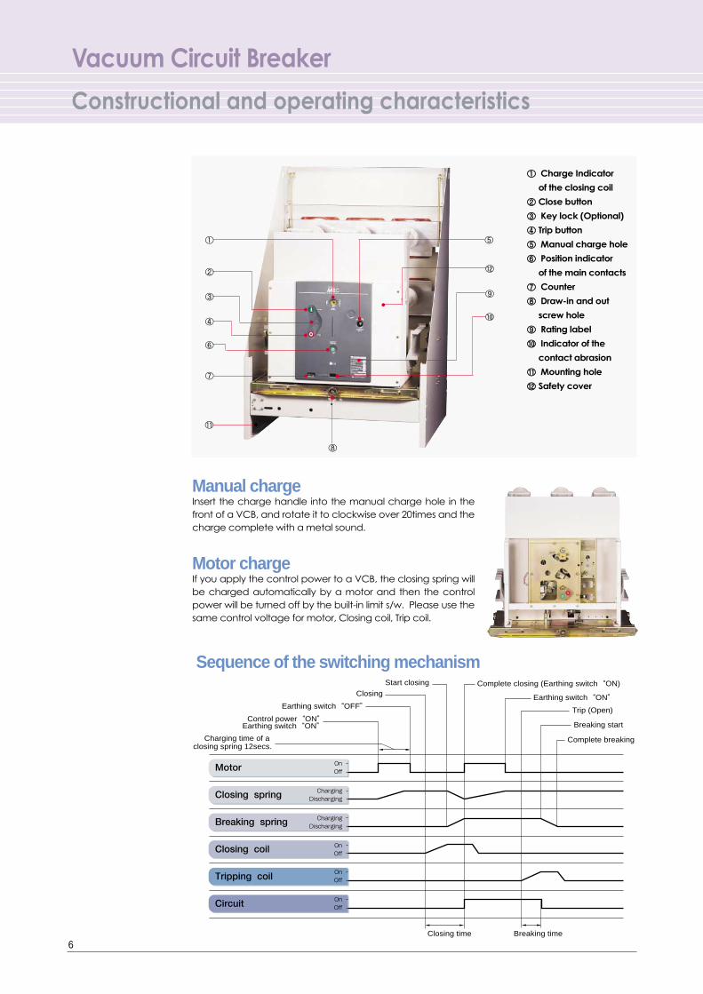
Manual chargeInsert the charge handle into the manual charge hole in thefront of a VCB, and rotate it to clockwise over 20times and thecharge complete with a metal sound.
Motor chargeIf you apply the control power to a VCB, the closing spring willbe charged automatically by a motor and then the controlpower will be turned off by the built-in limit s/w. Please use thesame control voltage for motor, Closing coil, Trip coil.
Sequence of the switching mechanism
Charging time of a closing spring 12secs.
Start closing Complete closing (Earthing switch“ON)Closing
Earthing switch“OFF” Earthing switch“ON”
Earthing switch“ON” Control power“ON”
Motor
Closing spring
Breaking spring
Closing coil
Tripping coil
Circuit
Closing time Breaking time
Complete breaking
Breaking start
Trip (Open)
Charging
Discharging
Charging
Discharging
On
Off
On
Off
On
Off
On
Off
①
②
③
④
⑤
⑥
⑦
⑧
⑨
⑩
⑪
⑫
①① Charge Indicator
of the closing coil
②② Close button
③③ Key lock (Optional)
④④ Trip button
⑤⑤ Manual charge hole
⑥⑥ Position indicator
of the main contacts
⑦⑦ Counter
⑧⑧ Draw-in and out
screw hole
⑨⑨ Rating label
⑩⑩ Indicator of the
contact abrasion
⑪⑪ Mounting hole
⑫⑫ Safety cover
7
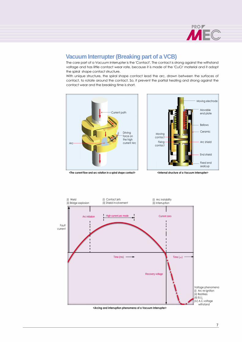
Vacuum Interrupter (Breaking part of a VCB)
<The current flow and arc rotation in a spiral shape contact>
<Arcing and interruption phenomena of a Vacuum Interrupter>
Current path
Drivingforce onthe highcurrent ArcArc
(i) Weld(ii) Bridge explosion
(i) Contact jets(ii) Shield involvement
(i) Arc instability(ii) Interruption
Current zero
Recovery voltage
Voltage phenomena(i) Arc re-ignition(ii) Restrikes(iii) B.I.L(iv) A.C.voltage
withstand
Arc initiation High current arc mode
Fault current
Time (ms) Time (㎲)
The core part of a Vacuum Interrupter is the 'Contact'. The contact is strong against the withstandvoltage and has little contact wear rate, because it is made of the 'CuCr' material and it adoptthe spiral shape contact structure. With unique structure, the spiral shape contact lead the arc, drawn between the surfaces ofcontact, to rotate around the contact. So, it prevent the partial heating and strong against thecontact wear and the breaking time is short.
<Internal structure of a Vacuum Interrupter>
Moving electrode
Movable end plate
Bellows
CeramicMoving
contact
Fixing contact
Arc shield
End shield
Fixed end sealcup
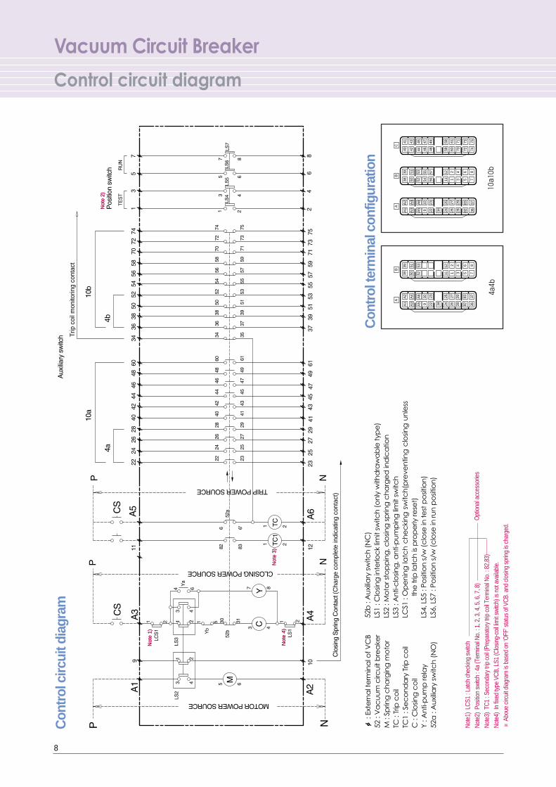
Vacuum Circuit Breaker
Control circuit diagram
8
Not
e 2)
Not
e 2)
Not
e 1)
Not
e 1)
Not
e 4)
Not
e 4)
Not
e 3)
Not
e 3)
(Cha
rge
com
plet
e in
dica
ting
cont
act)
Trip
coi
l mon
itorin
g co
ntac
t C
ontr
ol c
ircui
t dia
gram
ф: E
xte
rna
l te
rmin
al o
f VC
B52
: V
ac
uu
m c
ircu
it b
rea
ker
M :
Sprin
g c
ha
rgin
g m
oto
rTC
: Tr
ip c
oil
TC1
: Se
co
nd
ary
Trip
co
ilC
: C
losin
g c
oil
Y : A
nti-
pu
mp
rela
y52
a :
Au
xilia
ry s
witc
h (
NO
)
52b
: A
uxi
liary
sw
itch
(N
C)
LS1
: Clo
sing
inte
rloc
k lim
it sw
itch
(o
nly
with
dra
wa
ble
typ
e)
LS2
: Mo
tor s
top
pin
g, c
losin
g s
prin
g c
ha
rge
d in
dic
atio
nLS
3 : A
nti-
clo
sing
, an
ti-p
um
pin
g li
mit
switc
hLC
S1 :
Op
en
ing
latc
h c
he
cki
ng
sw
itch
(pre
ven
ting
clo
sing
un
less
the
trip
latc
h is
pro
pe
rly re
set)
LS4,
LS5
: Po
sitio
n s
/w (
clo
se in
test
po
sitio
n)
LS6,
LS7
: Po
sitio
n s
/w (
clo
se in
run
po
sitio
n)
Con
trol
term
inal
con
figur
atio
n
3434
73 75
8372
56
747
837
826
5
368
7
8382
3736
61 7159
60 70
1 342
5811
12
27 2925
26 2824
2 4
1 31112
2726
2928
2524
45 47 49
4452
53
46 485654
5755
A6
10 23
A5
5352
9 22
A6
A5
10 23
9 22
C
41 43
B
40 42
38 505139
A
A2
A4
A1
A3
B
39 51
38 50
A
A2
A1
A4
A3
10a10b
4a4b
Not
e1)
LCS1
: La
tch
chec
king
switc
h
Not
e2)
Posit
ion
switc
h : 4
a (T
erm
inal
No.
: 1,
2, 3
, 4, 5
, 6, 7
, 8)
Not
e3)
TC1
: Sec
onda
ry tr
ip c
oil (
Prep
arat
ory
trip
coil T
erm
inal
No.
: 82
,83)
Not
e4)
In fi
xed
type
VC
B, L
S1 (C
losin
g-co
il lim
it sw
itch)
is n
ot a
vaila
ble.
※Ab
oue
circu
it di
agra
m is
bas
ed o
n ‘O
FF’ s
tatu
s of
VC
B. a
nd c
losin
g sp
ring
is ch
arge
d.
Opt
iona
l acc
esso
ries
9
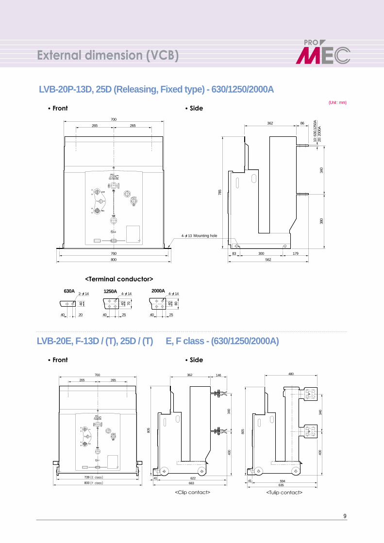
External dimension (VCB)
630A 1250A 2000A2-ф14
40 20 40 25 40 25
807040 4040
4-ф14 4-ф14
760
800 562
362 86
83 179300
380
785
340
700
265265
10: 6
30,1
250A
20: 2
000A
4-ф13 Mounting hole
700
265 265
362
62241
663
805
340
400
146
739 (E class)
800 (F class)
805
340
400
480
59441635
LVB-20P-13D, 25D (Releasing, Fixed type) - 630/1250/2000A
LVB-20E, F-13D / (T), 25D / (T) E, F class - (630/1250/2000A)
��Front ��Side
<Clip contact> <Tulip contact>
<Terminal conductor>
��Front ��Side
(Unit : mm)
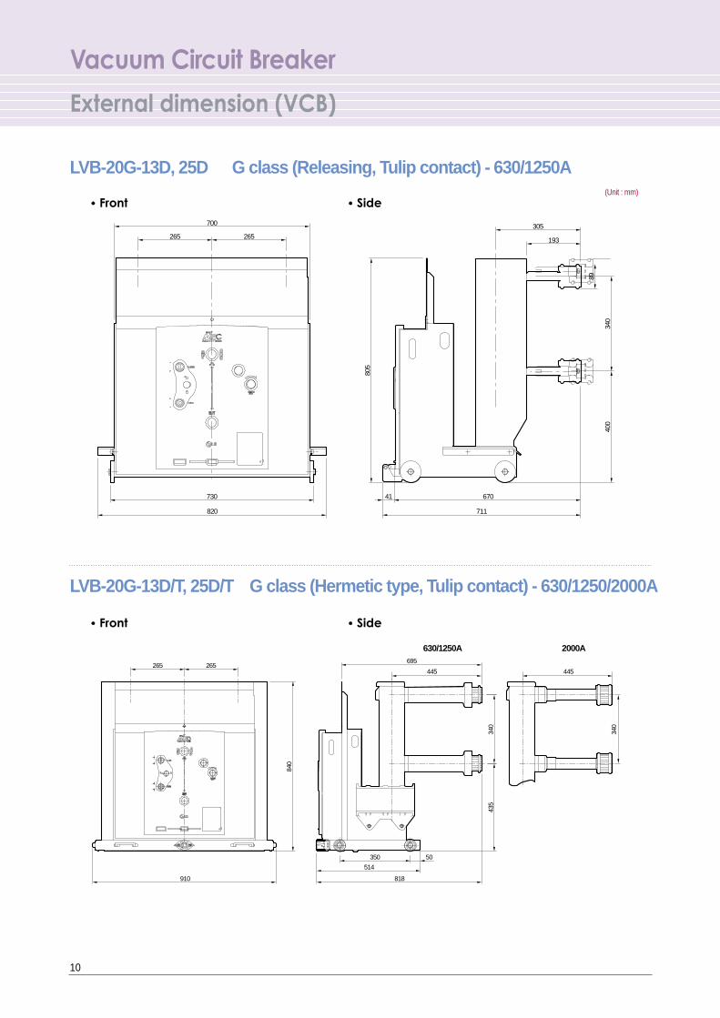
Vacuum Circuit Breaker
External dimension (VCB)
10
(Unit : mm)
LVB-20G-13D, 25D G class (Releasing, Tulip contact) - 630/1250A
LVB-20G-13D/T, 25D/T G class (Hermetic type, Tulip contact) - 630/1250/2000A
��Front ��Side
��Front ��Side
700
730 67041
305
193
805
400
340
89
820 711
265 265
2000A630/1250A
265 265
910
350 50
514
818
840
435
340
340
695
445 445
1000
1035
st: 260
285
A 340
1033
404.
5
T
Insulation barrier
B
22
1120
1167
12.5kA 630A 25kA 630A 12.5kA 1250A25kA 1250, 2000AInsulation barrier
62
20.5
67 4712
0
300
300
8517
7.5
120
100
8517
810
0
5050
2-ф14
7-ф14 Mounting hole
ф6.5(Eartating)
2-ф14 4-ф14
40
660
260
110 400 400 210
168
2040 20
5025
0
265
265
145
820
40 20
ф6.5
40
40
10
46
30
11
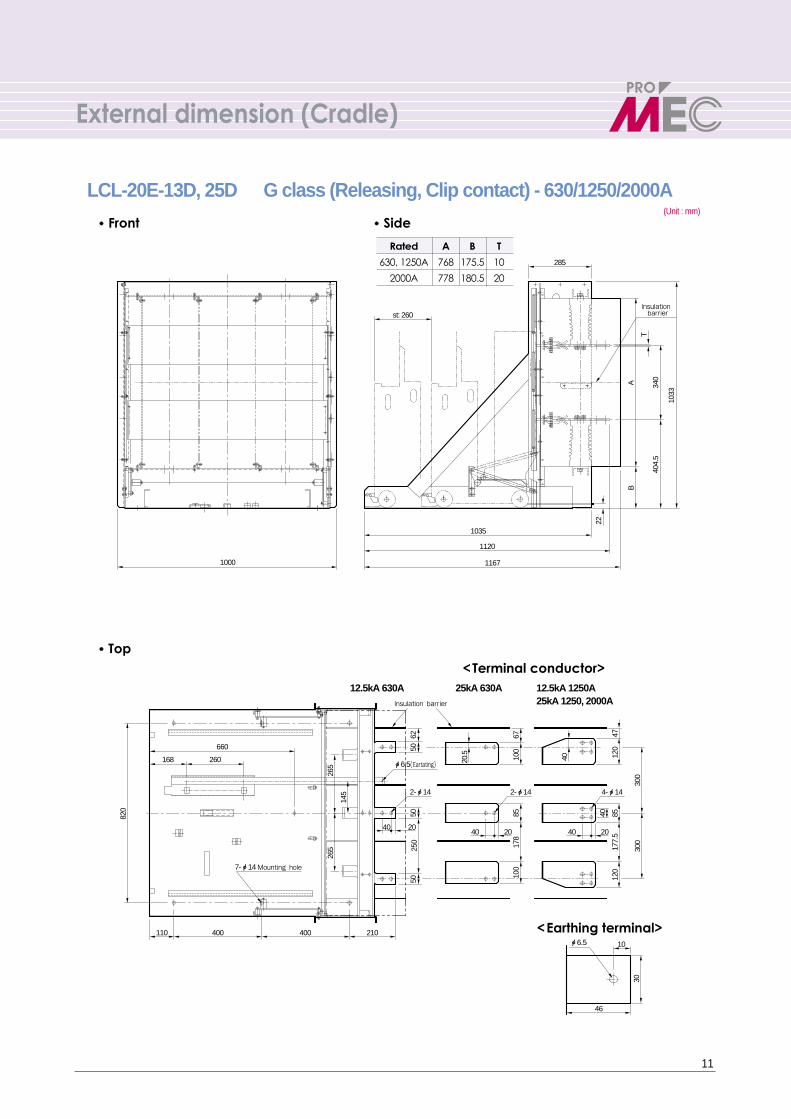
External dimension (Cradle)
(Unit : mm)
LCL-20E-13D, 25D G class (Releasing, Clip contact) - 630/1250/2000A
��Front ��Side
��Top<Terminal conductor>
Rated A B T
630, 1250A 768 175.5 10
2000A 778 180.5 20
<Earthing terminal>
12
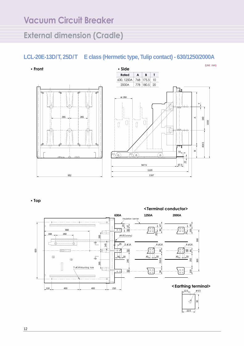
Vacuum Circuit Breaker
External dimension (Cradle)
(Unit : mm)
LCL-20E-13D/T, 25D/T E class (Hermetic type, Tulip contact) - 630/1250/2000A
��Front ��Side
��Top
952
st: 260
265 265
947.5
1120
1167
22
404.
534
0A
T
B
1033
97.5
10
6750 90
90 100
202
80
300
300
100
45
8021
0.5
47
50
145
820
265
265
245
50
25
660
260168
400 400 210110
2-ф14 4-ф14 4-ф14
40 20 40 20 40 20
630A 1250A 2000A
40
20
40.5 42
ф6.512.5
22.5
30
Insulation barrier
7-ф14 Mounting hole
ф6.5(Eartating)
Rated A B T
630, 1250A 768 175.5 10
2000A 778 180.5 20
<Terminal conductor>
<Earthing terminal>
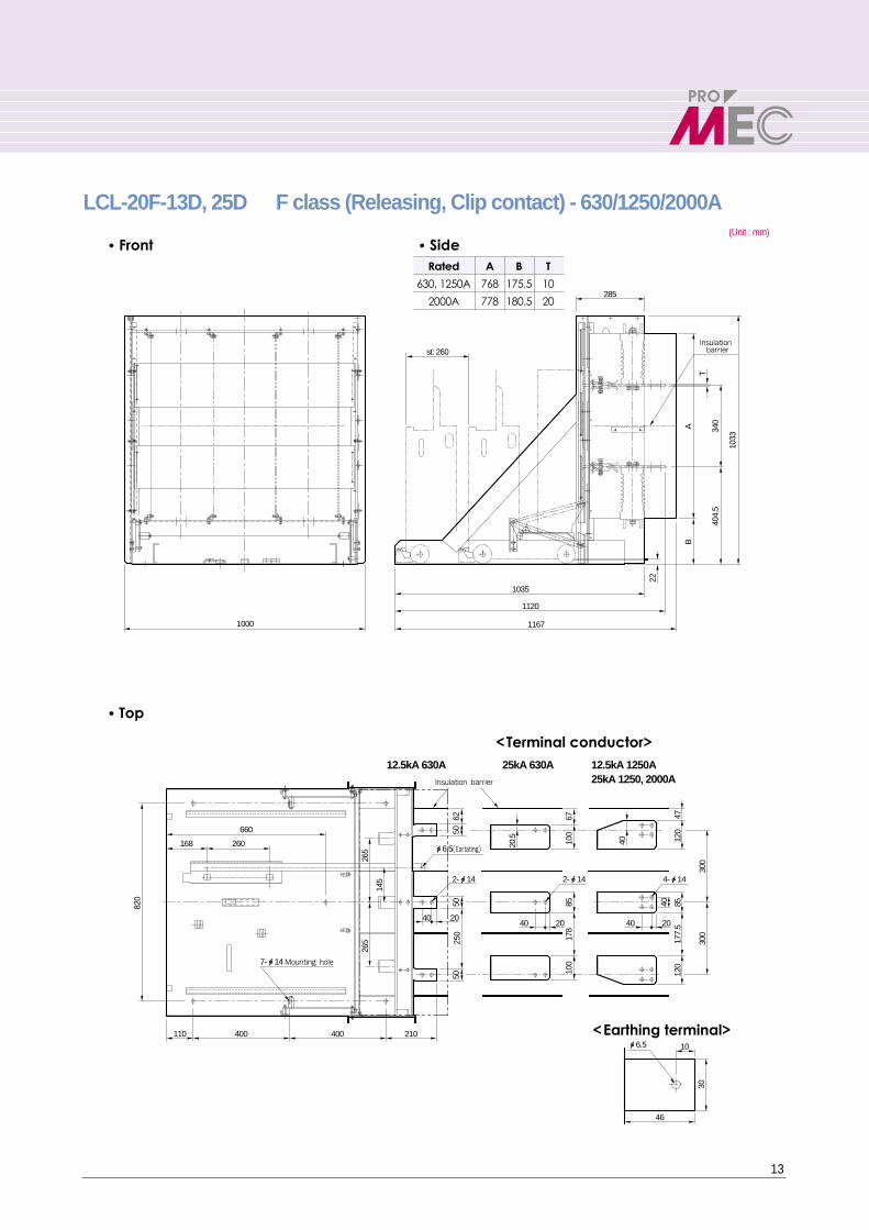
13
(Unit : mm)
LCL-20F-13D, 25D F class (Releasing, Clip contact) - 630/1250/2000A
��Front ��Side
��Top
1000
1035
st: 260
285
A 340
1033
404.
5
T
Insulation barrier
B
22
1120
1167
12.5kA 630A 25kA 630A 12.5kA 1250A25kA 1250, 2000AInsulation barrier
62
20.5
67 4712
0
300
300
8517
7.5
120
100
8517
810
0
5050
2-ф14
7-ф14 Mounting hole
ф6.5(Eartating)
2-ф14 4-ф14
40
660
260
110 400 400 210
168
2040 20
5025
0
265
265
145
820
40 20
ф6.5
40
40
10
46
30
Rated A B T
630, 1250A 768 175.5 10
2000A 778 180.5 20
<Terminal conductor>
<Earthing terminal>

Vacuum Circuit Breaker
External dimension (Cradle)
14
(Unit : mm)
LCL-20F-13D/T, 25D/T F class (Hermetic type, Tulip contact) - 630/1250/2000A
��Front ��Side
��Top
1000
1035
st: 260
285
1120
1167
22
BA 34
040
4.5
1033
T
Insulation barrier
12.5kA 630A 1250A 2000A
660
168
820
265
265
145
40
210400400110
20
2-ф14 4-ф14 4-ф14
40 20 40 20
67 47 4510
080
100
202
300
300
9090
8021
0.5
50
20
5050
245
260 42
40.5
40
ф6.5 10
46
30
Insulation barrier
7-ф14 Mounting hole
ф6.5(Eartating)
Rated A B T
630, 1250A 768 175.5 10
2000A 778 180.5 20
<Terminal conductor>
<Earthing terminal>
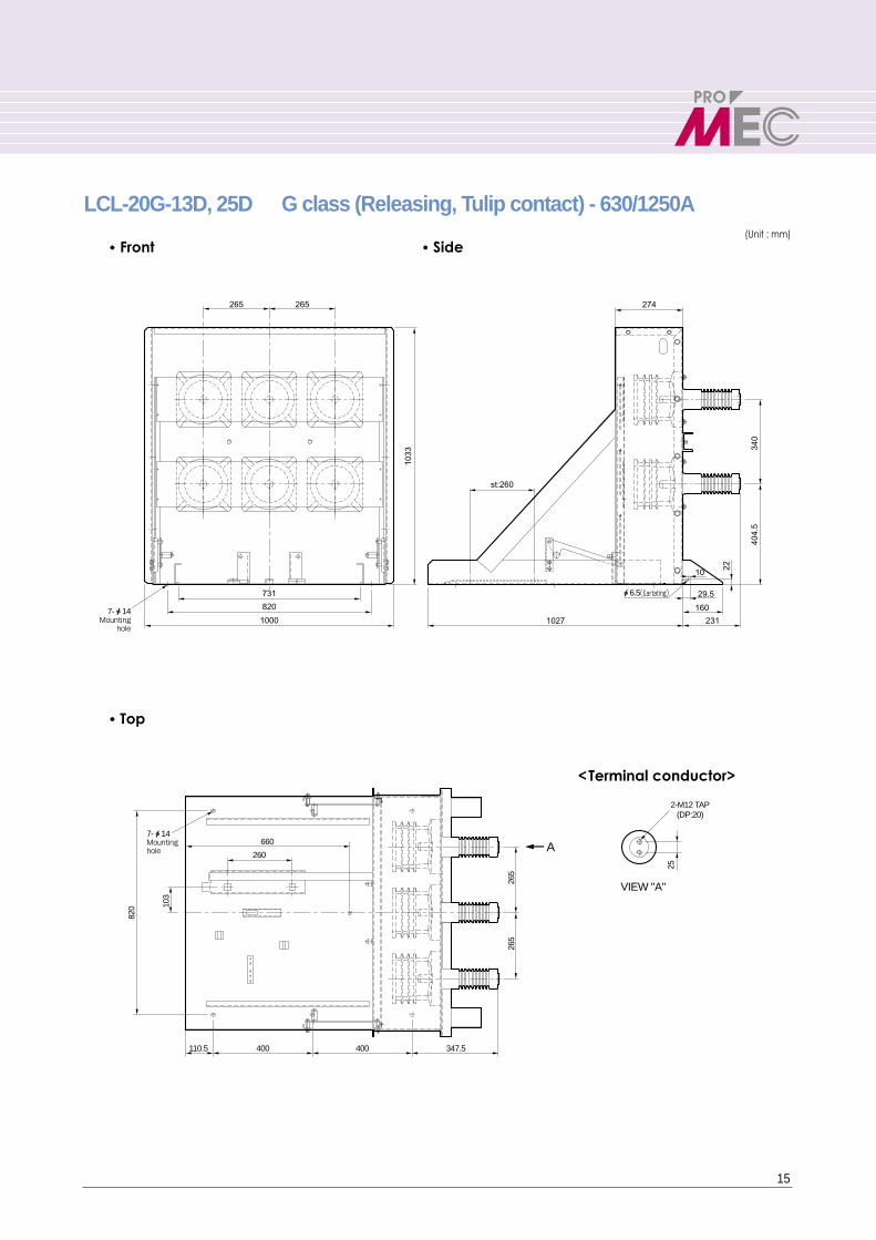
15
(Unit : mm)
LCL-20G-13D, 25D G class (Releasing, Tulip contact) - 630/1250A
��Front ��Side
��Top
265265
731
st:260
1033
340
404.
5
22
29.5
160
10
1027 231
820
1000
274
7-ф14 Mounting
hole
ф6.5(Eartating)
347.5400
25
2-M12 TAP(DP:20)
400110.5
660
260
265
103
820
265
A
VIEW "A"
7-ф14Mountinghole
<Terminal conductor>
Vacuum Circuit Breaker
External dimension (Cradle)
16
(Unit : mm)
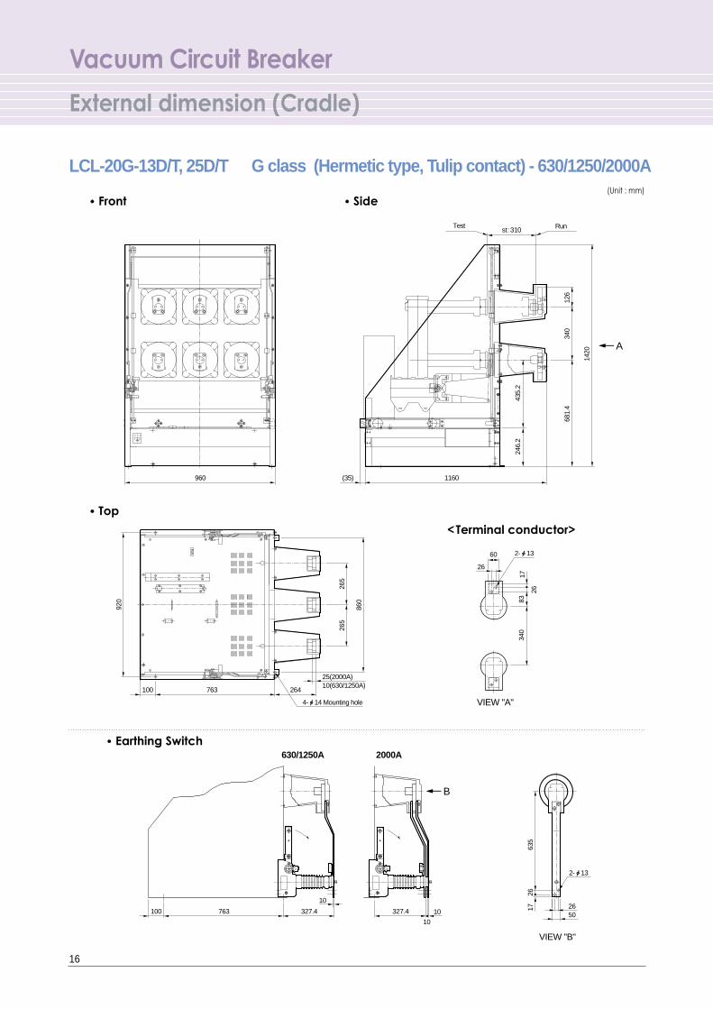
LCL-20G-13D/T, 25D/T G class (Hermetic type, Tulip contact) - 630/1250/2000A
��Front ��Side
RU
N
VIEW "A"
A
Test Run
960 1160(35)
246.
243
5.2
681.
4
1420
340
126
763 264
265
265
860
340
8317
60
26
26
920
25(2000A)10(630/1250A)
100
4-ф14 Mounting hole
2-ф13
st: 310
VIEW "B"
B
763 327.4 327.4 1026
635
1726
5010
10
100
2-ф13
2000A630/1250A
��Top
��Earthing Switch
<Terminal conductor>
17
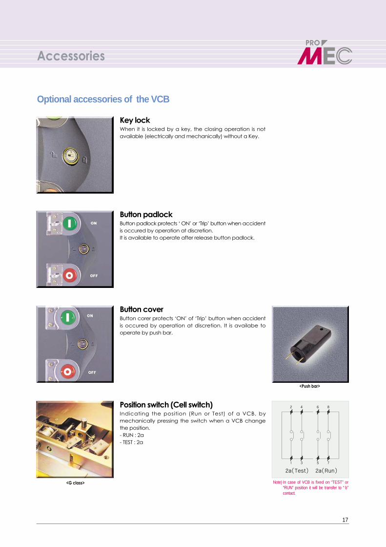
When it is locked by a key, the closing operation is notavailable (electrically and mechanically) without a Key.
Key lock
Button padlock protects ‘ ON’ or ‘Trip’ button when accidentis occured by operation at discretion.It is available to operate after release button padlock.
Button padlock
Button corer protects ‘ON’ of ‘Trip’ button when accidentis occured by operation at discretion. It is availabe tooperate by push bar.
Button cover
Indicating the position (Run or Test) of a VCB, bymechanically pressing the switch when a VCB changethe position. - RUN : 2a- TEST : 2a
Position switch (Cell switch)
<G class>
Optional accessories of the VCB
<Push bar>
2a(Test) 2a(Run)
Accessories
Note) In case of VCB is fixed on “TEST” or“RUN” position it will be transfer to “ b”contact.
Vacuum Circuit Breaker
Accessories
18
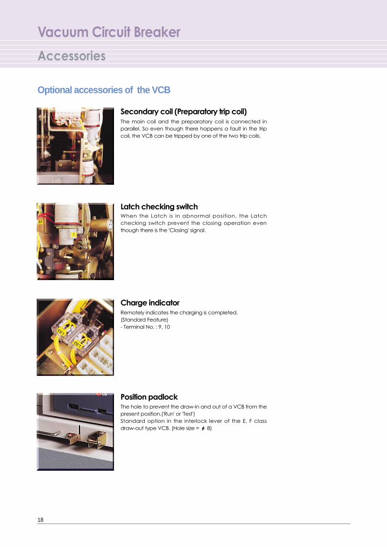
The main coil and the preparatory coil is connected inparallel. So even though there happens a fault in the tripcoil, the VCB can be tripped by one of the two trip coils.
Secondary coil (Preparatory trip coil)
Remotely indicates the charging is completed. (Standard Feature) - Terminal No. : 9, 10
Charge indicator
When the Latch is in abnormal position, the Latchchecking switch prevent the closing operation eventhough there is the 'Closing' signal.
Latch checking switch
The hole to prevent the draw-in and out of a VCB from thepresent position.('Run' or 'Test') Standard option in the interlock lever of the E, F classdraw-out type VCB. (Hole size = ф 8)
Position padlock
Optional accessories of the VCB

19
For the safety during the maintenance of a VCB panel,discharge the charging current in the load side of a VCBwith this earthing switch.
Earthing switch (for G class draw-out type only)
Indicates the 'ON' or 'OFF' status of the earthing switch.(5a5b)
Position switch of the earthing switch (for G class draw-out type only)
The hole to prevent the accident through carelessnessearthing switch operation, the locking of the earthingswitch is available when the switch is in 'OFF' position. (Holesize = ф 8)
Padlock of earthing switch (for G class draw-out type only)
To prevent the accident through carelessness earthingswitch operation, the earthing switch can be changed to'ON' position after releasing the lock by magnetizing thecoils.
Locking coil of earthing switch (for G class draw-out type only)
Optional accessories of a Cradle
<Earthing Switch Position Switch>
<Earthing Switch Locking Coil>

Vacuum Circuit Breaker
Accessories
20
To prevent the insert a VCB to a cradle, when the ratingsof VCB and cradle are different.
Code plate (Miss insertion prevention) -for E,F class draw-out type only
The hole to lock the shutters (load and line side) in closeposition, to increase the safety during the maintenance ofa VCB draw-out position. (Hole size = �8)
Shutter padlock -Standard offer in the draw-out type
The auxiliary switch (3a4b), which Indicate the 'ON' or 'OFF'condition of a VCB, but operated only when the VCB is in'Run' state. (Installed in the bottom of a cradle)
Mechanically operated cell switch (MOC)-for G class draw-out type only
The auxiliary switch (3a4b), which indicate the 'Run' stateof a VCB and is operated by the movement of a VCBframe. (Installed in the bottom of a cradle)
Truck operated cell switch (TOC) -for G class draw-out type only
Note) #11, 21 are Early “b” contact
Note) #11, 21 are Early “b” contact
Optional accessories of a Cradle
To prevent the insert draw-in/out handle to a screwhole by operating G class VCB temporarily
Padlock
21
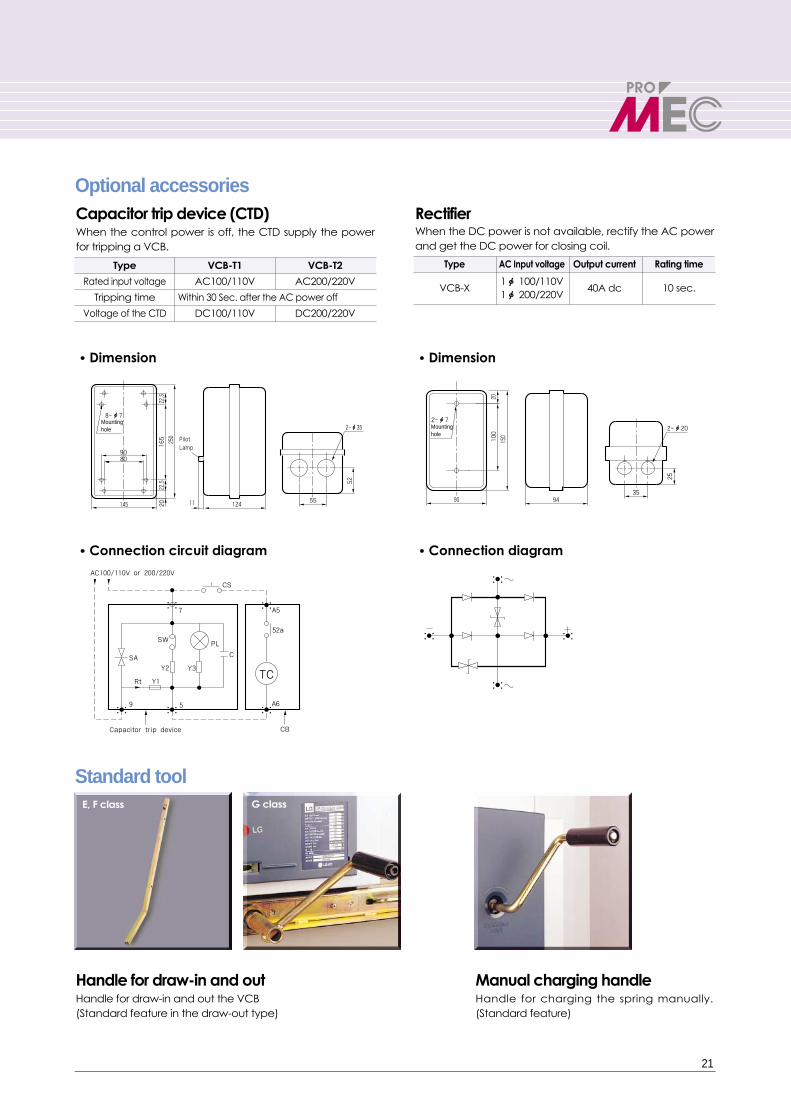
��Dimension��Dimension
��Connection diagram��Connection circuit diagram
Standard tool
When the control power is off, the CTD supply the powerfor tripping a VCB.
Capacitor trip device (CTD)When the DC power is not available, rectify the AC powerand get the DC power for closing coil.
Rectifier
Optional accessories
Handle for charging the spring manually.(Standard feature)
Manual charging handleHandle for draw-in and out the VCB(Standard feature in the draw-out type)
Handle for draw-in and out
E, F class G class
Type VCB-T1 VCB-T2
Rated input voltage AC100/110V AC200/220V
Tripping time Within 30 Sec. after the AC power off
Voltage of the CTD DC100/110V DC200/220V
Type AC Input voltage Output current Rating time
VCB-X 1ф 100/110V
40A dc 10 sec.1ф 200/220V
5512411
80
145
52
250
165
22.5
22.5
20
90
2-ф35
Pilot Lamp
Mounting hole
8-ф7
25
3594
2010
090
150
2-ф72-ф20Mounting
hole
A5
A6
52a
Capacitor trip device
TC
22
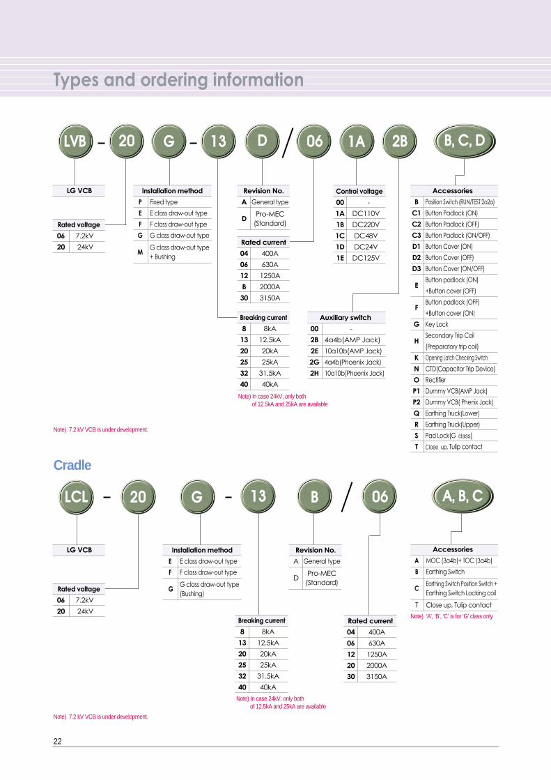
Types and ordering information
Cradle
LLVVBB GG2200 1133 DD 0066 BB,, CC,, DD11AA 22BB
Note) ‘A’, ‘B’, ‘C’ is for ‘G’ class only
Note) In case 24kV, only both of 12.5kA and 25kA are available
Note) 7.2 kV VCB is under development.
Note) 7.2 kV VCB is under development.
LG VCB
Rated voltage
06 7.2kV
20 24kV
Installation method
P Fixed type
E E class draw-out type
F F class draw-out type
G G class draw-out type
MG class draw-out type+ Bushing
Revision No.
A General type
DPro-MEC
(Standard)
Control voltage
00 -
1A DC110V
1B DC220V
1C DC48V
1D DC24V
1E DC125V
Rated current
04 400A
06 630A
12 1250A
B 2000A
30 3150A
Breaking current
8 8kA
13 12.5kA
20 20kA
25 25kA
32 31.5kA
40 40kA
Breaking current
8 8kA
13 12.5kA
20 20kA
25 25kA
32 31.5kA
40 40kA
Auxiliary switch
00 -
2B 4a4b(AMP Jack)
2E 10a10b(AMP Jack)
2G 4a4b(Phoenix Jack)
2H 10a10b(Phoenix Jack)
Accessories
B Position Switch (RUN/TEST:2a2a)
C1 Button Padlock (ON)
C2 Button Padlock (OFF)
C3 Button Padlock (ON/OFF)
D1 Button Cover (ON)
D2 Button Cover (OFF)
D3 Button Cover (ON/OFF)
EButton padlock (ON)
+Button cover (OFF)
FButton padlock (OFF)
+Button cover (ON)
G Key Lock
HSecondary Trip Coil
(Preparatory trip coil)
K Opening Latch Checking Switch
N CTD(Capacitor Trip Device)
O Rectifier
P1 Dummy VCB(AMP Jack)
P2 Dummy VCB( Phenix Jack)
Q Earthing Truck(Lower)
R Earthing Truck(Upper)
S Pad Lock(G class)
T Close up, Tulip contact
LG VCB
Rated voltage
06 7.2kV
20 24kV
LLCCLL 2200 GG 1133 BB 0066 AA,, BB,, CC
Installation method
E E class draw-out type
F F class draw-out type
GG class draw-out type(Bushing)
Revision No.
A General type
DPro-MEC
(Standard)
Accessories
A MOC (3a4b)+ TOC (3a4b)
B Earthing Switch
CEarthing Switch Position Switch +Earthing Switch Locking coil
T Close up, Tulip contact
Note) In case 24kV, only both of 12.5kA and 25kA are available
Rated current
04 400A
06 630A
12 1250A
20 2000A
30 3150A

23
Memo

2003-07
ACB(A) 2001 / Jul. 2003 Printed in Korea STAFF