vacuum-assisted gas atomization of liquid metal
TRANSCRIPT

Atomization and Sprays, 22 (7): 581–601 (2012)
VACUUM-ASSISTED GAS ATOMIZATION OFLIQUID METAL
S. P. Mates,1,∗ S. D. Ridder,1 F. S. Biancaniello,1 & T. Zahrah2
1National Institute of Standards and Technology, Gaithersburg, MD,20899, USA
2MATSYS, Inc., Sterling, VA, 20166, USA
∗Address all correspondence to S. P. Mates E-mail: [email protected]
Original Manuscript Submitted: 6/30/2012; Final Draft Received: 10/18/2012
Vacuum-assisted gas atomization of liquid metal is explored. The investigation is motivated by ob-servations of liquid metal atomization that indicate that secondary atomization is sustained overan extended distance from the nozzle tip. Increasing the velocity of the gas flow downstream of thenozzle exit by lowering the nozzle back pressure below ambient may therefore improve atomizationefficiency. Supersonic jets grow in length when the nozzle back pressure is lowered due to an increasein the nozzle pressure ratio. However, since the nozzle mass flux remains fixed, any improvementsin vacuum-assisted atomization efficiency will be realized without any increase to the gas-to-metalmass flow ratio, which is of interest both academically and practically as gas consumption can becostly. Small (25-kg batch) atomization runs were performed using an Al-Cu-Ni glass-forming alloyin which a high-mass-flow vacuum system was employed to maintain a sub-ambient chamber pres-sure over the course of an entire run. The powder produced in this manner was then compared to theconventional method without the vacuum system operating. Results demonstrate that atomizing intoa partial vacuum decreases the frequency of the coarsest particles in the powder size distributions,leading to a narrower particle size distribution. Further, they underscore the importance of the axiallength scale affecting secondary atomization that is related to, but not fully described by, the gas-to-liquid mass flux ratio. The present experiments point out a significant and unexplored parameterspace that may be exploited to increase control over particle size distributions.
KEY WORDS: gas atomization, metal powder, particle size control
1. INTRODUCTION
Gas atomization of molten metal is a preferred method for producing high-quality spheri-cal metal powders with low oxygen content for use in advanced manufactured parts usingpowder metallurgy processing techniques (German, 2005). Other applications of note forthese powders include electronic solder paste, paints and pigments, rocket propellants,and raw material for additive manufacturing. The premium often placed on very fine(<50µm) powders has long motivated efforts to improve the fine particle yields through
1044–5110/12/$35.00 c© 2012 by Begell House, Inc. 581

582 Mates et al.
understanding and enhancing aerodynamic breakup (Ayers and Anderson, 1986; Klarand Fesko, 1984; Ridder and Biancaniello, 1988; Thompson, 1948;Unal and Robert-son, 1986). Through the efforts of these and other researchers, much has been learnedabout the physics of this rather unique application within the larger arena of twin-fluidatomization with applications such as combustion (Lefebvre, 1989). Much past effort toreduce or influence particle size (increase atomization “efficiency”) has been dominatedby efforts to enhance primary breakup at or very near the nozzle tip, motivated largely byearly fluid dynamic studies of atomization of viscous non-metallic liquids (Dombrowskiand Johns, 1963). Efforts to enhance breakup conditions here have focused on nozzle tipshape (Klar and Fesko, 1984; Miller et al., 1997; Mullis et al., 2011;Unal, 1988), usingtrumpet-shaped nozzles (Anderson et al., 2010) or linear arrangements (Walz, 1984) tothin the liquid stream as much as possible prior to its interaction with the atomizing gasat the nozzle exit. Such efforts parallel those in fuel injector design, within the consid-erable additional restrictions of having to deal with molten liquids with a propensity tofreeze solid and block the nozzle, which severely limits the scope of viable atomizergeometries. Powerful computational analysis methods are ever more frequently appliedto better understand atomization mechanisms and design improved nozzles (Markus andFritsching, 2006; Tong and Browne, 2009; Zeoli et al., 2012; Zhao et al., 1012).
Secondary atomization, by contrast, although generally considered important to thisprocess, has received less focus for its potential role in refining particle size and control-ling droplet size distributions. The importance of secondary breakup has been revealedby high-speed photography of atomization plumes and been analyzed in detail (Matesand Settles, 2005a;Unal, 1989; Yule and Dunkley, 1994). Droplets that are atomizedwell beyond the nozzle tip region will generally experience less aggressive aerodynamicconditions due to gas velocity decay, leading to coarser particles and wider particle sizedistributions. The mechanisms of turbulent mixing and droplet drag that cause gas veloc-ity decay give rise to the conceptual model of liquid metal atomization shown in Fig. 1,which is based on spray plume observations and emphasizes an extended secondarybreakup zone. Figure 1 shows Schlieren images (Settles, 2001) that indicate the extentof the supersonic gas flow region with and without liquid present, the latter using stop-motion microsecond-duration lighting (Mates and Settles, 2005a). Primary atomizationof the liquid core appears to be complete within about one nozzle diameter. Secondaryatomization apparently continues over an extended distance, as indicated by the appear-ance of large, incompletely atomized droplets well beyond the primary atomization zone.The Schlieren technique reveals qualitatively how the gas velocity decays significantlyover this distance: as the gas density approaches that of the surroundings as it decel-erates from supersonic speeds, the initially bright gas plume gradually blends into thebackground. Thus the large droplets that escape primary atomization intact eventuallybreak down under much reduced aerodynamic driving forces due to the decaying gasvelocity, which occurs by turbulent mixing with the surrounding gas and by drag exertedby the liquid.
Atomization and Sprays

Vacuum-Assisted Gas Atomization of Liquid Metal 583
33 ms exposure, gas-only
1 s exposure, tin atomizationµ
primarybreakup
Gas
Metal
secondary breakup
axisymmetric supersonic jet
wake
FIG. 1: Top: long-exposure Schlieren image of gas-only operation using a convergentnozzle. Middle: microsecond-exposure Schlieren image of metal atomization showinglarge un-atomized liquid ligaments (dark spots in center of jet) existing well downstreamof the nozzle tip. Bottom: conceptual sketch of atomization process showing a shortprimary breakup region and an extended secondary breakup zone.
Overall, the conceptual model of liquid metal atomization in Fig. 1 compares verywell with what has been observed in subsonic co-flowing atomizers when the gas mo-mentum flux is two orders of magnitude larger than the liquid momentum flux and theliquid Reynolds number is low. It has been called the “recirculating gas cavity” breakupregime in a comprehensive review of twin-fluid atomization (Lasheras and Hopfinger,2000), including an extended region of secondary breakup. Further, the importance ofsecondary atomization in determining the median droplet size is evident in the form ofthe empirical models developed to describe the behavior of these atomizers. Many highlycited models involve terms proportional to the gas-to-liquid flow ratio, either mass-based(Kim and Marshall, 1971; Lefebvre, 1991; Lubanska, 1970) or volume-based (Dunkley,2001; Nukiyama and Tanasawa, 1938–40). However, the literature also suggests thatsuch ratios have no fundamental role in promoting liquid instability. Many experimentalstudies demonstrate that the outcome of atomization can be fully described by intensiveproperties of the gas and liquid alone (Adelberg, 1968; Hsiang and Faeth, 1993; Wigg,
Volume 22, Number 7, 2012

584 Mates et al.
1964), including velocity, density, viscosity, surface tension, although a characteristiclength scale, such as droplet diameter, is needed as well. Such experiments invariablyinvolve the breakup of liquid droplets or streams injected into wind tunnels, where thegas flux dwarfs that of the liquid. Despite the fact that the local gas flow around a dis-integrating liquid droplet is very complex, the drop size distributions have neverthelessbeen successfully predicted from “freestream” aerodynamic conditions in these cases.Thus, in this case the amount of gas or liquid plays no role, proving that gas-to-liquidratio has no intrinsic influence on liquid instability.
The situation is dramatically different, however, for twin-fluid atomization processes,like the present one, where the gas and liquid flow rates are of the same order of magni-tude. A range of sensitivity of droplet size to gas-to-liquid ratio of between 0.1 and 10was suggested in Kim and Marshall (1971). For metal powder production, the gas-to-metal ratios (GMRs) are typically of order 1 (Lawley, 1992; Yule and Dunkley, 1994)due to economics, which favors high production rates (metal flow rates) and thus lowGMRs. An added bonus is that large metal flow rates prevent freeze-offs. As shownearlier, in this range of limited GMR, the freestream driving force decays significantlyalong the length of the plume, due to turbulent mixing and liquid drag. Thus, the useof GMR in these models may have been a way to account for thisaxial length scaleeffect that influences atomization performance in this regime. To illustrate, consideringthe gas flow by itself, it is known that, for supersonic atomization nozzles, the supersoniclength of the jet is proportional to the gas mass flow rate (Nagamatsu et al., 1996). Sec-ond, as demonstrated in subsonic co-flowing atomization of conventional (low freezingtemperature) liquids at high gas-to-liquid momentum ratios, the extent of the secondaryatomization zone is influenced by the liquid mass flux (Lasheras and Hopfinger, 2000).Thus, within this range, atomization efficiency can be influenced by altering secondaryatomization conditions, in ways not suggested by the more usual focus on primary atom-ization. According to the established empirical models, the most effective way to reducethe mean particle size is to simply increase GMR. Here, however, we attempt to influencethis axial length scale independent of GMR, by lowering the pressure of the atomizationchamber to increase the extent of the supersonic region without any additional gas massflow, in what we call vacuum-assist.
By virtue of the large nozzle stagnation pressures (P 0) typically used to atomizeliquid metal, the gas flow is substantially supersonic, and extended supersonic jets aretypical. This is true regardless of whether the nozzle is of “sonic” (convergent) design orof “supersonic” (convergent–divergent) design. For example, the supersonic jet shownin Fig. 1 is produced by a convergent, “sonic” nozzle. It produces an under-expanded su-personic jet of high Mach number, but with a series of repeating shock cells. Despite thisunder-expanded condition, this nozzle can produce a supersonic jet of similar length toa convergent–divergent nozzle due its annular, rather than round, gas orifice (Mates andSettles, 2005b). One method to enhance the supersonic jet length is to lower the pressureof the environment into which the nozzle exhausts, called the nozzle “back pressure.”
Atomization and Sprays

Vacuum-Assisted Gas Atomization of Liquid Metal 585
Here this is the pressure in the atomizing chamber,P ac. In many industrial gas atom-izers including the one used here, the spray plume is contained in an environmentallycontrolled chamber to limit oxygen pickup in the metal powder. Typically, the pressurein this chamber is at or slightly above ambient. By loweringP ac to well below this level,the overall pressure ratio across the gas nozzle is increased, leading to greater expansionof the gas and an elongated supersonic jet. For round nozzles, supersonic jet length isrelated to the pressure ratioP0/P ac (Nagamatsu et al., 1996):
Lsonic
D=
10γ− 1
[(P0
Pac
)γ− 1γ
− 1
]+ 0.8 (1)
Once the nozzle throat becomes sonic, its mass flow becomes restricted (choked). Low-ering the back pressure therefore increases the length of the supersonic jet without in-creasing the gas mass flow rate. Any benefits to efficiency that are achieved in this waywould cost nothing in terms of added gas flow, and would not necessarily change thegas-to-metal mass flow ratio, although the liquid flow can be influenced by changes tothe local aerodynamic conditions at the nozzle tip. It is interesting to note that currentempirical models based on GMR would fail to predict a reduction in particle size reduc-tion in this case. In fact, these models would predict a coarsening of particle (or droplet)size, as will be discussed later. As such, a positive demonstration of the vacuum-assisteffect will, in addition to the practical benefits of achieving increased process efficiency,provide additional insight into the fundamental nature of this liquid metal atomizationprocess, as well as other twin-fluid atomization processes where the gas-to-liquid mo-mentum flux ratio is large.
To investigate the effect of vacuum-assisted atomization, experiments were con-ducted using the NIST SiGMA (Supersonic inert Gas Metal Atomizer). This facilityis capable of operating with controlled and sustained sub-ambient pressures in the at-omizing chamber. Four 25 kg batches of an Al-Cu-Ni alloy were atomized, two withnear-ambient pressure maintained in the collection chamber and two having sub-ambientchamber pressure. This particular glass-forming alloy is being investigated for an appli-cation relating to ballistic penetrators using powder metallurgy consolidation techniques.Particle size analysis was conducted to determine the effect of the sub-ambient chamberpressure on the atomization efficiency.
2. EXPERIMENTAL
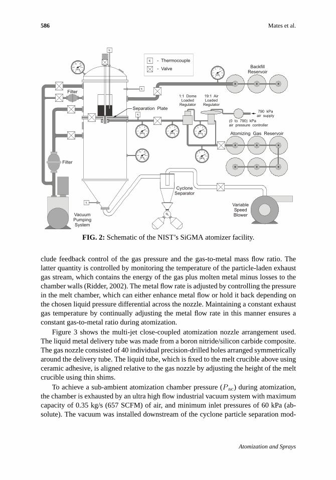
The NIST SiGMA atomizer, described in detail elsewhere (Ridder et al., 1992), is aninduction-melt, bottom-pour arrangement with melting and atomization performed un-der controlled atmosphere. A schematic of the facility is shown in Fig. 2. SiGMA iscapable of atomizing 25 kg heats of alloys of up to 2000 K melting temperature at atypical production rate of about 6 kg/min. Special features of the SiGMA atomizer in-
Volume 22, Number 7, 2012
586 Mates et al.
TC
0
1
2 3
4
5MPa
0
3
6 9
12
MPa15 0
3
6 9
12
MPa15
0
60
120 180
240
kPa300
0
60
120 180
240
kPa300
0
3
6 9
12
MPa15
0
3
6 9
12
MPa15
TC
TC
TC
BackfillReservoir
Separation Plate
TC - Thermocouple
- Valve
Filter
Filter
VacuumPumpingSystem
Atomizing Gas Reservoir
19:1 AirLoaded
Regulator
1:1 DomeLoaded
Regulator
(0 to 790) kPaair pressure controller
790 kPaair supply
VariableSpeedBlower
CycloneSeparator
FIG. 2: Schematic of the NIST’s SiGMA atomizer facility.
clude feedback control of the gas pressure and the gas-to-metal mass flow ratio. Thelatter quantity is controlled by monitoring the temperature of the particle-laden exhaustgas stream, which contains the energy of the gas plus molten metal minus losses to thechamber walls (Ridder, 2002). The metal flow rate is adjusted by controlling the pressurein the melt chamber, which can either enhance metal flow or hold it back depending onthe chosen liquid pressure differential across the nozzle. Maintaining a constant exhaustgas temperature by continually adjusting the metal flow rate in this manner ensures aconstant gas-to-metal ratio during atomization.
Figure 3 shows the multi-jet close-coupled atomization nozzle arrangement used.The liquid metal delivery tube was made from a boron nitride/silicon carbide composite.The gas nozzle consisted of 40 individual precision-drilled holes arranged symmetricallyaround the delivery tube. The liquid tube, which is fixed to the melt crucible above usingceramic adhesive, is aligned relative to the gas nozzle by adjusting the height of the meltcrucible using thin shims.
To achieve a sub-ambient atomization chamber pressure (P ac) during atomization,the chamber is exhausted by an ultra high flow industrial vacuum system with maximumcapacity of 0.35 kg/s (657 SCFM) of air, and minimum inlet pressures of 60 kPa (ab-solute). The vacuum was installed downstream of the cyclone particle separation mod-
Atomization and Sprays

Vacuum-Assisted Gas Atomization of Liquid Metal 587
FIG. 3: Gas nozzle assembly. Linear dimensions are in millimeters.
ules, as shown in Fig. 1 (labeled as variable speed blower). With a nominal gas flow of0.17 kg/s from the nozzle, the amount of gas being injected into the chamber is less thanhalf the throughput capacity of the vacuum system, allowing the chamber pressure toremain at sub-ambient pressures throughout a production run. Figure 4 shows that theatomization chamber can be maintained at about 60% of atmospheric pressure with thevacuum system operating over a wide range of nozzle pressures in the absence of metalflow.
0
0.2
0.4
0.6
0.8
1
1.2
0 1000 2000 3000 4000 5000 6000 7000
P o [kPa]
Pac/Patm
Vac On
Vac Off
FIG. 4: Atomization chamber pressure (P ac) relative to atmospheric pressure (P atm)reached with and without the vacuum system activated at various nozzle pressures (P 0).
Volume 22, Number 7, 2012

588 Mates et al.
Particle size analysis was performed using a sonic sieving technique (Biancanielloet al., 1990). The analysis was carried out for particle sizes between 5µm and 125µm.Particles larger than 125µm were removed prior to sieving, while sub–5µm particleswere allowed to pass through the sieve stack. In most cases, only a small amount ofmaterial was produced outside the size range analyzed. Because the powder size distri-butions produced by SiGMA are usually multimodal (Biancaniello et al., 1990), they arenot well represented by simple distributions such as the log-normal distribution.
3. RESULTS
Prior to performing atomization experiments at reduced pressures, the nozzle was op-erated under gas-only conditions withN2 to identify an operating regime appropriatefor atomizing liquid metal. An appropriate regime consists of a range of gas pressuresthat produce near-ambient to sub-ambient pressures at the tip of the liquid delivery tube.This condition is necessary to allow the liquid metal to flow out of the nozzle, which isoften referred to as the aspiration condition, because the nozzle can aspirate metal out ofthe tundish. Under certain aerodynamic conditions, or if the liquid tube is not properlyaligned to the gas nozzle, substantial positive pressures can develop at the nozzle tip,causing the liquid metal flow to arrest and freeze, blocking the tube (a “freeze-off”), orto actively “blow back,” two unwanted and possibly dangerous outcomes. Gas-only flowtests were performed into the pressure-controlled atomization chamber with and with-out the vacuum system in operation to identify an appropriate gas pressure that achievesacceptable aspiration for both normal (ambient) and sub-ambient pressures. The test re-sults are shown in Fig. 5, which plots aspiration pressure, or delivery tube pressure,P dt,against nozzle stagnation pressure,P0, for two values ofP ac: one with the vacuum sys-tem operating and one with the vacuum system turned off (normal operation). The twosets of data have similar character, both showing a sudden drop at a particular value ofP 0. This phenomenon, known as wake-closure, is associated with a sudden collapse inthe subsonic wake zone immediately downstream of the blunt nozzle tip and the forma-tion of a normal shock, or Mach disk, beyond the now-shortened wake zone (Mates andSettles, 2005b). Flow visualization images obtained from a similar annular atomizationnozzle are indicated in the figure for illustrative purposes. While seemingly dramatic,this effect usually has little influence on atomization performance because it does notoccur when liquid metal is flowing under typical operating conditions because the liquidmass flux raises the pressure in that region substantially. However, it is an important in-dicator of the range of nozzle pressures where stable metal flow can be achieved, sincelow nozzle tip pressures act to enhance metal flow and prevent freeze-offs. Based onthese aspiration pressure curves, an atomizing pressure of about 6.4 MPa was selectedfor the experiments. At this value ofP 0, the aspiration is well below ambient for bothregular and vacuum-assisted operation, indicating good prospects for stable atomization.In Fig. 6, the same aspiration pressure data are plotted against pressure ratio,P 0/P ac,
Atomization and Sprays

Vacuum-Assisted Gas Atomization of Liquid Metal 589
FIG. 5: Effect of atomizer chamber pressure (P ac) on nozzle aspiration behavior (P dt)(Vac On:P ac = 60± 6 kPa; Vac Off:P ac = 101± 3 kPa).
0
0.2
0.4
0.6
0.8
1
1.2
0 10 20 30 40 50 60 70 80 90 100
P o /P ac
Pdt/Pac
Vac On Expt#1
Vac On Expt#2
Vac Off
FIG. 6: Aspiration pressure (P dt) plotted against nozzle pressure ratio showing theMach number dependence of the wake-closure phenomena.
which illustrates that the gas dynamic behavior of the nozzle is fundamentally dependenton the Mach number (M ), which is related to pressure ratio through the relation
M =
√√√√ 2γ− 1
[(P0
Pac
)γ− 1γ
− 1
](2)
Volume 22, Number 7, 2012

590 Mates et al.
In the above equation,γ is the specific heat ratio. For nitrogen gas its value is 1.4.With an acceptable atomizing pressure window identified, four 23-kg batches of
CuAlNi were atomized at nozzle stagnation pressures (P 0) between 6.3 MPa and 6.5 MPaand a target GMR of 2.0, representing typical operating conditions for the SiGMA at-omizer. Two batches were produced with the vacuum system off, and two with the vac-uum system on. Each run took approximately 2.43 minutes to complete. Figure 7 plotsthe process data obtained for one of the vacuum-assisted atomization runs. As the plotdemonstrates, the atomizing parameters are kept nearly constant throughout the run.Only the nozzle stagnation pressure drifts upwards slightly during the run. The vacuumsystem maintains the chamber at a steady 0.72 atm, slightly higher than the 0.6 atmachieved during gas-only operation. This is thought to be a consequence of the gas tem-perature increase as heat is extracted from the liquid metal. Also plotted in Fig. 8 is theoutput from a photosensor pointed at the nozzle tip that is sensitive to the light emissionfrom the molten spray plume. This record indicates the portion of the run where moltenmetal is flowing.
To roughly quantify the aerodynamic effects of reducingP ac, we compute the prop-erties of equivalent perfectly expanded gas jets at the experimental values ofP 0/P ac.Although the actual (imperfectly expanded) jets will differ from these idealized ones,comparing the idealized flow conditions is a good point of reference for anticipatinghow atomization performance may be affected. The properties of interest include exitvelocity,ue, supersonic length,Lsonic, gas mass flow rate,mgas, the dynamic pressure,q, and the jet momentum,Q. Values ofmgas are obtained from an empirical fit to massflow versus nozzle pressure data:
mgas= 0.0000266 P0 (3)
0
10
20
30
40
50
60
70
80
0 25 50 75 100 125 150 175 200 225
Time [s]
Po/P
atm
, P
ho
tod
iod
e [
AU
]
0
1
2
3
4
5
6
Pa/P
atm
, G
MR
Po/Patm
Photodiode
Pa/Patm
GMR
P ac =P atm
FIG. 7: Process data obtained with vacuum system in operation.
Atomization and Sprays

Vacuum-Assisted Gas Atomization of Liquid Metal 591
FIG. 8: Time-averaged images of the radiant metal plume (gray levels inverted) at thenozzle tip for normal (A) and vacuum-assisted (B) atomization showing the elongationand narrowing of the plume due to greater gas flow expansion with the reduced chamberpressure. Linear dimensions are in millimeters.
Values ofq, ue, andQ are all determined from isentropic relations (White, 1986):
q = 0.5γPM2 (4)
ue = M√
γRT (5)
T =T0
1 + γ−12 M2
(6)
Q = mgasue. (7)
In Eq. (5),R is the gas constant, which for nitrogen is 297 J/kg·K, andT is the statictemperature at the exit condition.T is determined fromT 0, the gas stagnation tempera-ture, which is 300 K, using Eq. (6). Ideal aerodynamic conditions corresponding to each
Volume 22, Number 7, 2012

592 Mates et al.
experiment are listed in Table 1. The baseline experiments with no vacuum-assist arelabeled B1 and B2, while the vacuum-assisted experiments are labeled VA1 and VA2.Reducing the chamber pressure leads to a 30% increase inLsonic. While the exit ve-locity and momentum increase slightly, the dynamic pressure drops by 20 %. This ispotentially important, since this implies a smaller peak Weber number and thus a largerstable droplet size (Lane, 1951), which works against the goal of achieving more efficientatomization. This will be discussed in more detail below.
In Fig. 8, time-averaged images of the radiant atomization plume show the effectof the reduced chamber pressure on the plume structure. The video data were recordedat 2 frames per second (shutter speed = 1 ms) using a visible light digital video cam-era. The images are inverted (low gray level indicates high intensity, and vice versa)and contrast enhanced. Beginning at the tip of the liquid delivery tube, the radiant metalplume at first necks down then widens again to an abrupt maximum, after which it grad-ually narrows again to a point. The metal conforms to this shape due to the aerodynamicforces imposed on it in the nozzle tip region. There exists a region of separated gasflow, sometimes called the wake zone (Mates and Settles, 2005b), which is character-ized by low-velocity, swirling motion of the gas. This zone is surrounded by an annularregion of high-velocity, supersonic gas flow emanating from the gas orifice ring posi-tioned around the delivery tube. On the border of the wake zone, there can be significantinteraction between molten metal and high-speed gas, leading to vigorous atomization.Inside the wake zone, however, very little fine atomization occurs because of the low,swirling gas velocities present. The flow pattern here is also highly disrupted by thepresence of large clumps of molten metal. Figure 9 includes a sketch of the dominantgas dynamic features of the flow that are invisible in these direct plume images. Whenthe chamber pressure is reduced, the wake zone becomes narrower and longer due to thegreater expansion of the gas flow emanating from the nozzle. The internal shock wavegrows, and its interaction point with the wake (at the maximum width of the wake) ispushed farther downstream. This effect is similar to what is observed when the nozzlepressure (P 0) is increased whileP a remains fixed (Mates and Settles, 2005b), whichis the typical method employed in gas atomization to achieve finer atomization. As be-
TABLE 1: Isentropic flow conditions computed at experimental atomizing conditions
Expt.P 0 [kPa](±1%)a
P ac [kPa](±0.5%)
Mmgas [kg/s](±2%)
Lsonic
[m]ue [m/s] q [kPa] Q [N]
B1 6290 104.8 3.33 0.167 0.571 656 815 110
B2 6290 104.1 3.34 0.167 0.574 656 812 110
VA1 6500 73.1 3.61 0.173 0.752 671 666 116
VA2 6470 73.0 3.61 0.172 0.751 671 665 115aStated uncertainties reflect 95% confidence intervals.
Atomization and Sprays
Vacuum-Assisted Gas Atomization of Liquid Metal 593
Baseline
0
5
1015
20
25
30
3540
45
50
0 25 50 75 100 125 150 175 200 225 250
Particle Size (µm)
0
10
2030
40
50
60
7080
90
100
D(V,50) = 38.0 µm
D(V,10) = 10.6 µm
D(V,90) = 134.3 µm
Baseline Run B1
0
5
1015
20
25
30
3540
45
50
0 25 50 75 100 125 150 175 200 225 250
Particle Size (µm)
0
10
2030
40
50
60
7080
90
100
D(V,50) = 33.8 µm
D(V,10) = 9.3 µm
D(V,90) = 129.0 µm
Baseline Run B2
Vacuum-Assisted
0
5
1015
20
25
30
3540
45
50
0 25 50 75 100 125 150 175 200 225 250
Particle Size (µm)
0
10
2030
40
50
60
7080
90
100
D(V,50) = 34.1 µm
D(V,10) = 10.0 µm
D(V,90) = 108.1 µm
Vac-Assist Run VA1
0
5
1015
20
25
30
3540
45
50
0 25 50 75 100 125 150 175 200 225 250
Particle Size (µm)
0
10
2030
40
50
60
7080
90
100
D(V,50) = 33.4 µm
D(V,10) = 11.3 µm
D(V,90) = 106.4 µm
Vac-Assist Run VA2
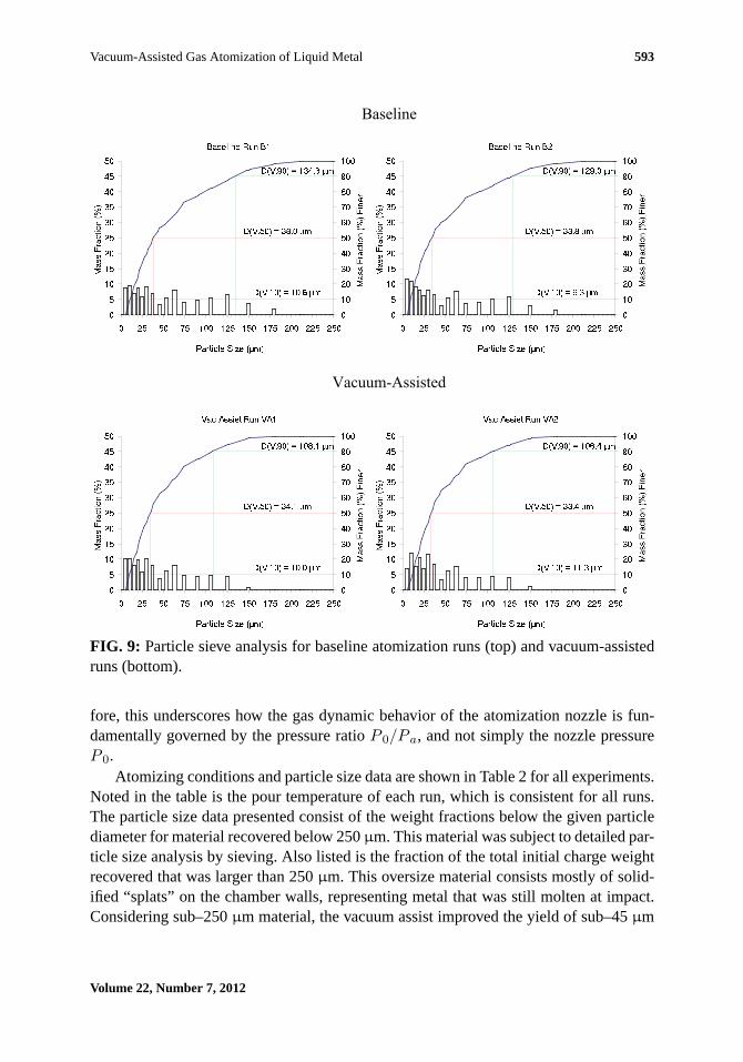
FIG. 9: Particle sieve analysis for baseline atomization runs (top) and vacuum-assistedruns (bottom).
fore, this underscores how the gas dynamic behavior of the atomization nozzle is fun-damentally governed by the pressure ratioP 0/P a, and not simply the nozzle pressureP 0.
Atomizing conditions and particle size data are shown in Table 2 for all experiments.Noted in the table is the pour temperature of each run, which is consistent for all runs.The particle size data presented consist of the weight fractions below the given particlediameter for material recovered below 250µm. This material was subject to detailed par-ticle size analysis by sieving. Also listed is the fraction of the total initial charge weightrecovered that was larger than 250µm. This oversize material consists mostly of solid-ified “splats” on the chamber walls, representing metal that was still molten at impact.Considering sub–250µm material, the vacuum assist improved the yield of sub–45µm
Volume 22, Number 7, 2012

594 Mates et al.
TABLE 2: Atomization parameters and mass-based particle size yields for baseline andvacuum-assisted runs
Expt.P 0 [kPa](±1%)a
P a [kPa](±0.5%)
T [◦C](±2%)
mmetal
[kg/min](±5%)
GMR< 250µm
% > 250µm% < 125
µm% < 45µm
B1 6290 104.8 1350 9.5 1.06 87.6 56.2 10.8
B2 6290 104.1 1350 7.4 1.35 89.1 60.3 5.1
VA1 6495 73.1 1350 10.0 1.04 94.4 62.5 11.0
VA2 6468 73.0 1350 9.1 1.14 94.2 64.6 18.3aStated uncertainties reflect 95% confidence intervals.
powder by 6.75% and the yield of sub–125µm powder by 9.1%. Oversize yields are notincluded in the average particle diameter because they lie outside the sieve measurementrange.
As Table 2 shows, while one vacuum-assisted run contained a reasonable percentageof >250µm material (11.0%), the other run had a much higher proportion of materiallost to “splats” (18.3%). Although it is impossible to estimate the size of the droplets thatproduced the splats, they are likely quite coarse since they remained molten all the way tothe chamber wall. This suggests poorer atomization performance for this run. However,this conclusion must be tempered by the fact that convective heat transfer may be lesseffective under partial-vacuum conditions, which may tend to increase the propensity forthe same size droplets to be molten at impact. The convective heat transfer coefficient,h, applicable for spheres in high Reynolds number flows, is given by Ranz and Marshall(1952):
h =k
D
[2 + 0.6Re0.5Pr0.33
]. (8)
Here,k is the thermal conductivity of the gas,D is the sphere diameter, and Re and Prare the Reynolds and Prandtl numbers, respectively. The effects of compressibility canbe accounted for using an adiabatic wall temperature to evaluate the heat flux (White,1986). Using Eq. (8), the heat transfer coefficient is decreased by 10% whenP a is re-duced, primarily due to the reduction in Reynolds number. A more detailed analysis isbeyond the scope of the present work. It is noteworthy that, if the material lost as splatsis counted as>125 µm yield, the averaged vacuum-assist yield improvement of sub–125 µm powder falls to 2.6%, while the improvement in sub–45µm powder falls to0.5%.
Figure 9 plots the detailed sieve analysis of all four batches for the sub–250µm pow-der. The most pronounced difference in the distributions produced under vacuum-assistis the reduced amount of the coarser particles in the distribution. The characteristic diam-eter which 90% of the particles by volume are smaller than,D(V, 90), averages 132µm
Atomization and Sprays

Vacuum-Assisted Gas Atomization of Liquid Metal 595
for the normal runs while for the vacuum-assist runs it is 107µm. That theD(V, 10)diameters are more comparable indicates that the vacuum-assist atomization reduces thefrequency of coarser particles but achieves no improvement in the finest particle sizes,leading to a narrower overall particle size distribution. This result is consistent withthe idea that a longer supersonic jet produces more complete secondary atomization.An aerodynamically limited atomization process is envisioned in which the gas velocitydoes not decay at all by the time secondary atomization is completed and all of the liquidis reduced to drop sizes below the stability limit determined from nozzle exit conditions.Under this condition one would obtain the finest mean diameter and narrowest parti-cle size distribution possible for given nozzle exit conditions. This state of maximummight exist at some limiting GMR where further increases in GMR have no measure-able effect on particle size. However, as will be argued here, GMR may not be the mostappropriate parameter to capture the axial length scale effect in this type of atomizationprocess.
Because reducingP a has many effects on the driving force for atomization besidesan elongated supersonic jet, as outlined in Table 1, it is simplistic to attribute the ob-served particle size refinement entirely to an increase in supersonic length alone. Twoadditional effects stand out besides the increased supersonic jet length. First, convectiveheat transfer from the droplets to the gas is reduced, as discussed earlier, which tends toincrease the opportunity for breakup. Second, as mentioned previously, because the dy-namic pressure of the gas flow,q, is reduced under vacuum-assist, the maximum stabledroplet size increases according to the well-known Weber number (We) criterion (Lane,1951). The Weber number is defined as
We =qD
σ. (9)
HereD is a characteristic liquid drop diameter andσ is the liquid surface tension. Aero-dynamic instability begins at a critical value Wecrit, which implies a maximum stabledroplet size ofDcrit. So asq increases,Dcrit decreases, yielding finer atomization. Thesetwo effects thus tend to counterbalance one another. Numerical simulation is needed tosort out these effects. All that can be stated for certain is that the vacuum-assist led tomeasureable refinement in particle size in a manner that is consistent with more effectivesecondary breakup.
Finally, in Table 3, several highly cited empirical models are compared for co-axial,co-flowing twin-fluid atomizers. These models are used now only for rule-of-thumb es-timates of atomization performance that can be readily evaluated, their role in atomizerdesign and detailed analysis having been replaced by the more powerful computationalfluid dynamics techniques. Nevertheless, these models represent the collective behaviorof significant amounts of experimental data obtained over more than 70 years. Here theyare used to predict the relative influence ofP a on particle size for the present experi-ments. The equations are cast in terms of variable definitions already introduced, with
Volume 22, Number 7, 2012

596 Mates et al.
TABLE 3: Predicted effect of vacuum-assist on particle size trend from highly citedempirical equations developed over the past 70 years
Equation Ref. Year CharacteristicDiameter
PredictedEffect ofVacuum-Assist
d =C1
ue
√σ
ρl+ C2
[µl√σρl
]0.45[ C3
GMVR
]1.5
21 1938 SMD decrease
d = d0C1
[µl
µg
(ρE
ρl
)2 1We
(1 +
1GMR
)]0.5
18 1970 D(V, 50) increase
d =C1
qC2+
C3
GMRC419 1971 D(V, 50) increase
d = d0C1/
[1 +
C2We
1 + 1GMR
]20 1989 D(V, 50) increase
d = C1σ√
GMVR22 2001 D(V, 50) decrease
the exception of the liquid surface tension,σ, and viscosity,µ, and density,ρ, of theliquid and gas (denoted by subscriptsl andg, respectively). The variabled representsan average particle diameter, withd0 a characteristic length scale, generally the diam-eter of the liquid orifice. Finally, the gas-to-metal volume ratio is denoted by GMVR.This term is analogous to GMR, but it is based on volume fluxes instead of mass fluxes.Since we are concerned with the relative effect of aerodynamic conditions on atomiza-tion performance rather than predictions of particle size, only the signs of the ratios ofdare determined for each model at conditions corresponding to the present experiments,with a positive ratio indicating an increased and a negative ratio indicating a decreasein d. SMD denotes the Sauter Mean Diameter whileD(V, 50) is the mass median diam-eter.
As Table 3 shows, only two models predict a decrease in median or Sauter meanparticle diameter while the other three predict an increase. Equations that utilize massflow ratio, GMR, predict an increased particle size resulting from the vacuum-assist dueto the reduction inq, which also lowers the Weber number. Equations that use GMVR,however, correctly predict the observed trend. Under vacuum conditions, the gas vol-ume flux for a given mass flux is higher owing to the lower density of the expandedjet, leading to a higher value of GMVR and thus a smaller mean particle diameter. Thatthe present experimental results are supported by some past observations is encourag-
Atomization and Sprays

Vacuum-Assisted Gas Atomization of Liquid Metal 597
ing, although the experimental conditions underpinning the two models that predict theobserved trend are not based on similar experimental conditions. In Dunkley (2001), thedata include low-density atomizing gases including helium, based on data reported inUnal (1989), and heated gas (Strauss, 1999), both of which show a decrease in meanparticle size. In both cases a higher value of GMVR is obtained because of reduced gasdensity, which illustrates why the models based on volume flux ratio correctly predictthe trend. Of course, there are other effects involved when using helium or heated gasbesides reducing the gas density. Most striking is the gas velocity, which dramatically in-creases for a given Mach number according to Eq. (5). Heat transfer will also be affected.These aerodynamic effects are presumably captured by an empirical constant (Dunkley,2001).
The question thus arises, is the GMVR parameter fundamentally related to the axiallength scales that are here hypothesized to cause the observed particle size refinement?To explore this, consider a sonic nozzle with a fixed throat area operated with values ofP 0 andP a corresponding to the present experiments. To compute the mass flows, weuse the following equation:
mgas=√
γ
(2
γ + 1
)(γ+1)/(2γ−2) A∗P0√RT0
. (10)
HereA∗ is the area of the sonic throat. Table 4 shows that neither heating the gas nor us-ing helium over nitrogen significantly changesLsonic, according to Eq. (2). Comparinghypothetical hot nitrogen and room temperature helium jets with the experimental ones,both show large increases in gas volume flux, which would tend to drive down particlesize according to these equations, but little or no change inLsonic, demonstrating thatthere is no link between gas volume flux andLsonic. Thus, the ability of these equationsto predict the trends observed is apparently fortuitous, and none of the empirical modelsin Table 3 correctly capture the behavior observed in the present experiments. Finally,
TABLE 4: Isentropic calculations comparing hypothetical behavior of heated nitro-gen and helium jets under normal and vacuum-assist conditions
GasP 0
[kPa]P a
[kPa]M
T 0
[K]
mgas
[kg/s]Lsonic
[m]ue
[m/s]Gas VolumeFlux [m3/s]
Nitrogen(γ = 1.4)
6290 104.8 3.33 300 0.167 0.574 656 0.0446500 73.1 3.61 300 0.173 0.752 671 0.0586290 104.8 3.33 600 0.118 0.574 928 0.0636500 73.1 3.61 600 0.122 0.752 949 0.083
Helium(γ = 1.67)
6290 104.8 3.33 300 0.067 0.532 1579 0.1556500 73.1 3.61 300 0.070 0.707 1606 0.195
Volume 22, Number 7, 2012

598 Mates et al.
Table 4 indicates that reducingP a may improve atomization performance if either he-lium or heated nitrogen is used.
Finally, these experiments point out that controllingP a can alter the aerodynamicconditions driving this variety of twin-fluid atomization in ways that are not normallyinvestigated. This has the potential to significantly expand the aerodynamic parameterspace for atomization processing beyond what is routinely explored. The potential pay-off is a greater control over particle size and size distribution, either in metal powderproduction or in other similar twin-fluid atomization processes.
4. CONCLUSION
This work has demonstrated the vacuum-assisted atomization of liquid metal. Under-lying the effect is the influence of the exhaust chamber pressure on the length of thesupersonic region of the gas jet extending away from the nozzle, which will tend toachieve more effective secondary breakup and thus a finer particle size distribution. Inparticular, this effect reduces the frequency of the coarsest particles in the distribution,without changing the size of the finest particles. As a result, vacuum-assist leads to anarrowing of the particle size distribution. Empirical models developed over the past 70years to predict mean particle size generally fail to predict the proper trend of vacuum-assist because they do not properly account for the axial length scale effect due to bothgas velocity decay and the physics of liquid breakup, which require time and distanceto complete. This work illustrates the importance of this axial length scale in twin-fluidatomization performance, and suggests how it might be used to control the behavior ofan atomizer in ways that have been virtually unexplored. Finally, it is critical to note thatthe vacuum-assist effect, and in general the axial length scale effect discussed here, arelikely important only in a limited range of atomization conditions. In this range, possiblybetween 0.1< GMR < 10 as suggested by Kim and Marshall (1971), turbulent mixingand liquid drag effects exacerbate the decay in relative velocity between gas and liquidbefore atomization is driven to its aerodynamic limit.
ACKNOWLEDGMENTS
The authors gratefully acknowledge the help of Paul Boyer, Rodney Jiggetts and RobertParke for their assistance in this work at NIST and for years of dedicated service to theNIST SiGMA atomizer facility, which is now permanently decommissioned.
REFERENCES
Adelberg, M., Mean drop size resulting from the injection of a liquid jet into a high speed gasstream,AIAA J., vol. 6, pp. 1143–1147, 1968.
Atomization and Sprays

Vacuum-Assisted Gas Atomization of Liquid Metal 599
Anderson, I. E., Byrd, D., and Meyer, J., Highly tuned gas atomization for controlled preparationof coarse powder,Mat.-Wiss. Werkstofftech., vol. 41, pp. 504–512, 2010.
Ayers, J. D. and Anderson, I. E., Method for generating fine sprays of molten metal for spraycoating and powder making, US Patent No. 4,619,845, 1986.
Biancaniello, F. S., Conway, J. J., Espina, P. I., Mattingly, G. E., and Ridder, S. D., Particle sizemeasurement of inert gas atomized powder,Mat. Sci. Eng., A, vol. 124, pp. 9–14, 1990.
Dombrowski N. and Johns, W. R., The aerodynamic instability and disintegration of viscousliquid sheets,Chem. Eng. Sci., vol. 18, pp. 203–214, 1963.
Dunkley, J. J., An analysis of the gas atomization process, inProc. of the Nice European Congressand Exhibition on Powder Metallurgy, vol. 4, p. 99, 2001.
German, R. M.,Powder Metallurgy & Particulate Materials Processing, Metal Powder IndustriesFederation, Princeton, NJ, 2005.
Hsiang, L.-P. and Faeth, G. M., Drop properties after secondary breakup,Int. J. Multiphas. Flow,vol. 19, pp. 721–735, 1993.
Kim, K. Y. and Marshall, Jr., W. R., Drop-size distributions from pneumatic atomizers,AIChEJ., vol. 17, pp. 575–584, 1971.
Klar, E. and Fesko, J. W., Atomization,Metals Handbook, 9th ed., Vol. 7, American Society forMetals, Metals Park, OH, 1984.
Lane, W. R., Shatter of drops in streams of air,Ind. Eng. Chem., vol. 43, pp. 1312–1317, 1951.
Lasheras, J. C. and Hopfinger, E. J. Liquid jet instability and atomization in a coaxial gas stream,Ann. Rev. Fluid Mech., vol. 32, pp. 275–308, 2000.
Lawley, A.,Atomization: The Production of Metal Powders, Metal Powder Industries Federation,Princeton, NJ, 1992.
Lefebvre, A. H.,Atomization and Sprays, Hemisphere Publishing Corporation, New York, 1989.
Lefebvre, A. H., Twin-fluid atomization: Factors influencing mean drop size, Keynote Lecture,in Proc. of the Fifth International Conference on Liquid Atomization and Spray Systems, ed.H. G. Semerjian, NIST, Gaithersburg, MD, p. 49, 1991.
Lubanska, H., Correlation of spray ring data for gas atomization of liquid metals,JOM-J. Met.,pp. 45–49, 1970.
Markus, S. and Fritsching, U., Discrete break-up modeling of melt sprays,Int. J. Powder Metall.,vol. 42, no. 4, pp. 23–32, 2006.
Mates, S. P. and Settles, G. S., A Study of liquid metal atomization using close-coupled nozzles,Part 1: Gas dynamic behavior,Atomization Spray, vol. 15, pp. 19–40, 2005a.
Mates, S. P. and Settles, G. S., A Study of liquid metal atomization using close-coupled nozzles,Part 2: Atomization behavior,Atomization Spray, vol. 15, pp. 41–60, 2005b.
Miller, R. S., Miller, S. A., and Wojcik, L. A., Close-Coupled Atomization Utilizing Nonaxisym-metric Melt Flow, US Patent No. 5,601,781, 1997.
Volume 22, Number 7, 2012

600 Mates et al.
Mullis, A. M., McCarthy, I. N., and Cochrane, R. F., High speed imaging of the flow duringclose-coupled gas atomisation: Effect of melt delivery nozzle geometry,J. Mater. Process.Tech., vol. 211, pp. 1471–1477, 2011.
Nagamatsu, H. T., Sheer, Jr., R. E., and Horvay, G., Supersonic jet noise theory and experiments,NASA SP-207, 1969.
Nukiyama, S. and Tanasawa, Y.,Trans. Soc. Mech. Eng., vol. 4–6, no. 1–6, 1938–40.
Ranz, W. E. and Marshall, Jr., W. R., Evaporation from drops—Part I,Chem. Eng. Prog., vol. 48,pp. 141–146, 1952.
Ridder, S. D., Measurement and control of metal flow-rate in a gas-metal atomizer, inAdvancesin Powder Metallurgy & Particulate Materials, Part 3—Particulate Production & Binders,Metal Powder Industries Federation, Princeton, N.J., 2002.
Ridder, S. D. and Biancaniello, F. S., Process control during high pressure atomization,Mater.Sci. Eng., vol. 98, pp. 47–51, 1988.
Ridder, S. D., Osella, S. A., Espina, P. I., and Biancaniello, F. S., Intelligent control of particlesize distribution during gas atomization,Int. J. Powder Metall., vol. 28, pp. 133–147, 1992.
Settles, G. S.,Schlieren and Shadowgraph Techniques, Springer, Berlin, 2001.
Strauss, J. T., Hotter gas increases atomization efficiency,Met. Powder Rpt., vol. 11, pp. 24–28,1999.
Thompson, J. S., A study of process variables in the production of aluminium powder by atom-ization,J. Inst. Met., vol. 74, pp. 101–132, 1948.
Tong, M. and Browne, D. J., Modelling compressible gas flow near the nozzle of a gas atomiserusing a new unified model, I,Comput. Fluids, vol. 38, pp. 1183–1190, 2009.
Unal, A., Influence of nozzle geometry in gas atomisation of rapidly solidified aluminium alloys,Mater. Sci. Tech., vol. 4, pp. 909–915, 1988.
Unal, A., Liquid break-up in gas atomization of fine aluminum powders,Met. Trans., B, vol.20B, pp. 61–69, 1989.
Unal, A. and Robertson, D. G. C., Pilot plant gas atomizer for rapidly solidified metal powders,Int. J. Rapid Solidif., vol. 2, pp. 219–229, 1986.
Walz, A., Metal powders and a process for the production thereof, US Patent #4,534,917, 1984.
Wigg, L. D., Drop-size prediction for twin-fluid atomisers,J. Inst. Fuel, vol. 37, pp. 500–505,1964.
White, F. M.,Fluid Mechanics, 2nd ed., McGraw-Hill, New York, 1986.
Yule, A. J. and Dunkley, J. J.,Atomization of Melts for Powder Production and Spray Deposition,Oxford University Press, 1994.
Zeoli, N., Tabbara, H., and Gu, S., Three-dimensional simulation of primary break-up in a close-coupled atomizer,Appl. Phys., A, vol. 108, pp. 783–792, 2012.
Zhao, W. J., Cao, F. Y., Ning, Z. L., Zhang, G. G., Li, Z., and Sun, J. F., A computational fluid dy-
Atomization and Sprays

Vacuum-Assisted Gas Atomization of Liquid Metal 601
namics (CFD) investigation of the flow field and the primary atomization of the close coupledatomizer,Comput. Chem. Eng., vol. 40, pp. 58–66, 2012.
Volume 22, Number 7, 2012