vacu-jet & two piece flo-jet - vhgmc · vacu-jet & two piece flo-jet fig. 57 ... vent boss,...
TRANSCRIPT

-
"STOP" POSITION
Fig. 55 - Adjust Choke Link
astcl] Carburetor<all carburetor and fuel tank as an assembly...okthrottle link into carburetor throttle and
.. verner lever. (For various hook-ups, seee:note Control, Section 4). Raise carburetor-:0 place, insert a new gasket and fasten withunting screws.
stall governor spring. Install ground wire and""":::otecontrol where used. Fig. 56,
Fig. 56 - Instoll Carburetor
Choke-A-Matic Remote Controls~e Remote Controls, Section 4, for illustra-ns by engine model.
Carburetor Adj ustmen t.-The initial setting of the needle valve, Fig. 57,.. made by turning the needle valve all the wayI . then turning out 116 turns. Final adjust-ent is made with engine running.
:-.:te carburetor should be adjusted with the fuel. ank approximately half full, with the engine-_nning at approximately 3000 RPM, turn ther.eedle valve in until the engine starts to lose-peed, (lean mixture) then open needle valveery slowly until engine begins to run unevenly.This mixture will seem to be too rich but will~ correct for good performance under full load.
iiold throttle in idling position. Engine shouldrdle no slower than 1750 RPM. Turn idle speedadjustment screw until this speed is reached.
CARBURETIONVacu-Jet & Two Piece Flo-Jet
Fig. 57 - Carburetor Adjustment
TWO PIECE FLO-JET CARBURETOR REPAIRLARGE and SMALL LINE
Fig. 59 - Two Piece Carburetor
Check Upper Carburetor Body for WarpageWith carburetor assembled and body gasket inplace, if a .002" feeler gauge can be insertedbetween the upper and lower bodies at the airvent boss, just below the idle valve, the upperbody is warped and should be replaced. Fig. 59.
17
CARBURETIONTwo Piece Flo-Jet
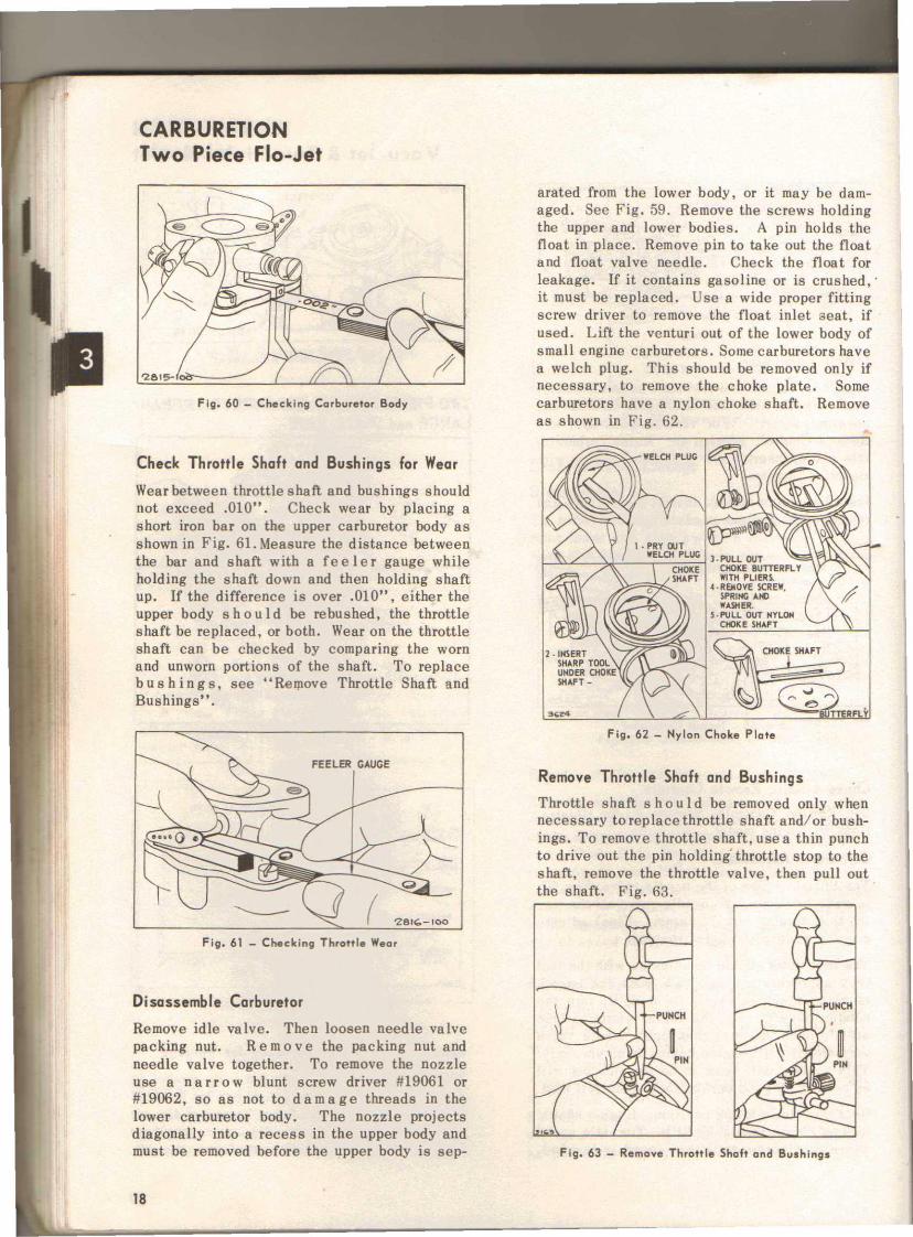
Fig. 60 - Checking Carburetor Body
Check Throttle Shaft and Bushings for Wear
Wearbetween throttle shaft and bushings shouldnot exceed .010". Check wear by placing ashort iron bar on the upper carburetor body asshown in Fig. 61. Measure the distance betweenthe bar and shaft with a fe e 1e r gauge whileholding the shaft down and then holding shaftup. If the difference is over .010", either theupper body should be rebushed, the throttleshaft be replaced, or both. Wear on the throttleshaft can be checked by comparing the wornand unworn portions of the shaft. To replacebus hi n g s , see ., Remove Throttle Shaft andBushings" .
FEELER GAUGE
arated from the lower body, or it may be dam-aged. See Fig. 59. Remove the screws holdingthe upper and lower bodies. A pin holds thefloat in place. Remove pin to take out the floatand float valve needle. Check the floa t forleakage. If it contains gasoline or is crushed,'it must be replaced. Use a wide proper fittingscrew driver to remove the float inlet seat, ifused. Lift the venturi out of the lower body ofsmall engine carburetors. Some carburetors havea welch plug. This should be removed only ifnecessary, to remove the choke plate. Somecarburetors have a nylon choke shaft. Removeas shown in Fig. 62.
281(;-100
Fig. 61 - Checking Throttle Wear
Disassemble Carburetor
Remove idle valve. Then loosen needle valvepacking nut. Rem 0 ve the packing nut andneedle valve together. To remove the nozzleuse a n a r row blunt screw driver #19061 or#19062, so as not to damage threads in thelower carburetor body. The nozzle projectsdiagonally into a recess in the upper body andmust be removed before the upper body is sep-
18
Fig. 62 - Nylon Choke Plate
Remove Throttle Shaft and Bushings
Throttle shaft s h 0 u1d be removed only whennecessary to replace throttle shaft and/ or bush-ings. To remove throttle shaft, use a thin punchto drive out the pin holdingthrottle stop to theshaft, remove the throttle valve, then pull outthe shaft. Fig. 63.
Fig. 63 - Remave Throttle Shaft and Bushings
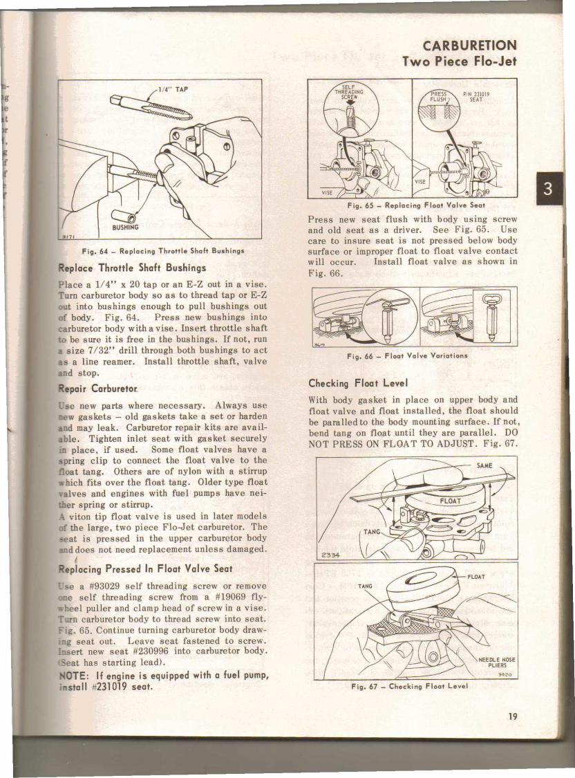
Fig. 64 - Replacing Throttle Shaft Bushings
Replac:e Throttle Shaft BushingsPlace a 1/4" x 20 tap or an E-Z out in a vise.Turn carburetor body so as to thread tap or E-Zout into bushings enough to pull bushings outof body. Fig. 64. Press new bushings intocarburetor body with a vise. Insert throttle shaftto be sure it is free in the bushings. If not. runa size 7/32" drill through both bushings to actas a line reamer. Install throttle shaft. valveand stop.
Repai r Carburetor,Lse new parts where necessary. Always usenew gaskets - old gaskets take a set or hardenand may leak. Carburetor repair kits are avail-able. Tighten inlet seat with gasket securelyn place, if used. Some float valves have aspring clip to connect the float valve to thefloat tang. Others are of nylon with a stirrupwhioh fits over the float tang. Older type floatvalves and engines with fuel pumps have nei-ther spring or stirrup.A viton tip float valve is used in later modelsf the large, two piece Flo-Jet carburetor. Theseat is pressed in the upper carburetor bodyand does not need replacement unless damaged.
(
Replac:ing Pressed In Float Valve SeatUse a #93029 self threading screw or removene self threading screw from a #19069 fly-heel puller and clamp head of screw in a vise.
Turn carburetor body to thread screw into seat.Fig. 65. Continue turning carburetor body draw-.:1g seat out. Leave seat fastened to screw.Insert new seat #230996 into carburetor body.Seat has starting lead).NOTE: If engine is equipped with a fuel pump,instnl] #231019 seat.
CARBURETIONTwo Piece Flo-Jet
PIN 231019SEAT
Fig. 65 - Replacing Float Valve Seat
Press new seat flush with body using screwand old seat as a driver. See Fig. 65. Usecare to insure seat is not pressed below bodysurface or improper float to float valve contactwill occur. Install float valve as shown inFig. 66.
Fig. 66 - Float Valve Variations
Chec:king Float LevelWith body gasket in place on upper body andfloat valve and float installed, the float shouldbe paralled to the body mounting surface. If not,bend tang on float until they are parallel. DONOT PRESS ON FLOAT TO ADJUST. Fig. 67.
Fig. 67 - Checking Float Level
19

CARBURETIONTwo Piece Flo-Jet
Assemble Carburetor
Assemble venturi and venturi gasket to lowerbody. Be sure holes in the venturi and venturigasket are aligned. Some models do not havea removable venturi. Install choke parts andwelch plug if previously removed. Use a sealeraround the welch plug to prevent entry of dirt.
Fasten upper and lower bodies together with themounting screws. Screw in nozzle with narrowblunt screw driver #19061 or #19062, being care-ful that nozzle tip enters the recess in the up-per body. Fig. 68. Tighten nozzle securely.Screw in needle valve and idle valve until theyjust seat. Back off needle valve 1-112 turns.Do not tighten packing nut. Back off idle valve3/4 turn. These settings are approximately cor-rect. Final adjustment will be made when en-gine is running.
Fig. 69 - Adjust Carburetor
Choke-A-Matic Remote Control
On Choke-A-Matic carburetors, the remote con-trol must be correctly adjusted in order to ob-tain pro per operation of the choke and stopswitch.
Choke-A-Mat ic Adi ustment
Typical remote control installations, used withChoke-A-Matic carburetors, are shown in Fig.70. To adjust, move remote control lever to"Fast" position. Choke actuating lever "A"should just contact choke link, or lever "B",as shown in Fig. 70. If not, loosen screw "C"slightly, and move casing and wire "D" in orout to obtain this con d it ion and re-tightenscrew "C".
Fig. 70 - Choke·A·Matic Controls (Typical)
Additional control variations are illustrated inControls. Section 4.
Fig. 68 - Assemble Carburetor
Carburetor Adjustment
Start engine and allow to warm up at 3UOO RPM.Turn needle valve in until engine misses (leanmixture) then turn it out past smooth operatingpoint until engine runs unevenly (rich mixture).Turn needle valve to the mid-point between richand lean 80 engine runs smoothly. Hold throttleat idle position and set idle speed, adjustingscrew until engine idle speed is 1750 RPM -Aluminum Engines. NOTE: 1200 RPM - CastIron Engines. Hold throttle at idle position andturn idle valve in (lean) and out (rich) until en-gine idles smoothly. Fig. 69. If necess ary,correct idle speed. Release throttle - engineshould accelerate without hesitation or sputter-ing. If engine does not accelerate properly, thecarburetor should be readj usted, usually to aslightly richer mixture of needle valve.
20

CARBURETIONTwo Piece Flo-Jet _ Automatic Choke
AUTOMATIC CHOKE_ ng Device and Throttle Control..nua l friction control may be used to limit
- t'le movement, to any pre-set position. It, ~_mmonly used for two purposes. 1. To re--,., the throttle to a "no-load" position on a-;>. generator, etc.: 2. For cold weather
, r.ing on governed idle engines. The throttle- easily be kept in a "near closed" position,r.e starting, which is most favorable for coldchar starts. Fig. 71.
Hold choke shaft so thermostat lever is free.At room temperature the screw in the thermo-stat collar should be in the center of the stops,if not, loosen stop screw and adjust.
Loosen set screw on lever of thermostat assem-bly. Slide lever to right or left on shaft to in-sure free movement of choke link in any posi-tion. Rotate thermostat shaft clockwise untilstop screw strikes tube. Fig. 73. Hold in po-sition and set lever on the thermostat shaft sothat choke valve will be held open about 1/8"from closed position. Then tighten set screwin lever.
Rotate thermostat shaft counter-clockwise untilstop screw strikes the opposite side of tube.Fig. 73. Then open choke valve manually untilit stops against the top of the choke link open-ing. The choke valve should now be open ap-proximately 1/8" as before.
Automatic Choke Adjust
Fig. 71 - Idling Device and Throttle Control
Remote Throttle ControlThe remote throttle control opens the carbure-.or throttle until the full governed speed is ob-.ained , at which point the governor takes overcontrol of the throttle. At any point below thegoverned speed, the throttle is held in a fixedposition and the engine speed will vary withthe load. Fig. 72.
Fig. 73 - Ad just Automatic Choke
F i9' 72 - Remote Throttle Contra I
Check position of counter-weight lever. Withthe choke valve in wide open position (hori-zontal) the counter-weight lever should alsobe in a horizontal position with free end towardthe right.
Operate the choke manually to be sure that allparts are free to move without binding or rub-bing in any position.
21