vacon nx io boards user manual dpd00884a en
DESCRIPTION
bTRANSCRIPT

vacon nxac drives
basic i/o boardsexpander i/o boards
adapter boards
user manual
vacon • 1
INDEX
Document ID: DPD00884ADate: 25.01.2012
1. General information .......................................................................................31.1. Board slots on the control board of Vacon NXS and NXP ..............................................31.2. Board Slots on the control board of Vacon NXL .............................................................41.3. Option board types ..........................................................................................................51.4. Technical data .................................................................................................................61.4.1. Isolation ...........................................................................................................................71.4.2. Analogue inputs (mA/V) ...................................................................................................71.4.3. Analogue outputs (mA/V) ................................................................................................71.4.4. Control voltage (+24V/EXT +24V) .....................................................................................71.4.5. Digital input signal conversion .......................................................................................81.5. Hardware protections ...................................................................................................101.5.1. Terminal block coding ...................................................................................................101.5.2. Board slot guides and allowed slots .............................................................................101.6. Type identification number ...........................................................................................111.7. Defining functions to inputs and outputs ......................................................................111.8. Defining a terminal for a certain function with NCDrive programming tool ...............121.9. Option board related parameters .................................................................................13
2. Installation of Vacon Option Boards .............................................................142.1. Control cables ...............................................................................................................162.1.1. Cable grounding ............................................................................................................162.2. Board information sticker .............................................................................................17
3. Descriptions of Vacon option boards ............................................................183.1. Basic boards OPTA_ ......................................................................................................183.1.1. OPTA1 ............................................................................................................................193.1.2. OPTA2 ............................................................................................................................233.1.3. OPTA3 ............................................................................................................................243.1.4. OPTA4 ............................................................................................................................253.1.5. OPTA5 ............................................................................................................................293.1.6. OPTA7 ............................................................................................................................333.1.7. OPTA8 ............................................................................................................................393.1.8. OPTA9 ............................................................................................................................433.1.9. OPTAL ............................................................................................................................443.1.10. OPTAE ..........................................................................................................................463.1.11. OPTAN .........................................................................................................................503.2. I/O Expander Boards OPTB_ .........................................................................................543.2.1. OPTB1 ............................................................................................................................553.2.2. OPTB2 ............................................................................................................................573.2.3. OPTB4 ............................................................................................................................583.2.4. OPTB5 ............................................................................................................................593.2.5. OPTB8 ............................................................................................................................603.2.6. OPTB9 ............................................................................................................................623.2.7. OPTBB ...........................................................................................................................63
Tel. +358 (0) 201 2121 • Fax +358 (0)201 212 205
vacon • 2
3.2.8. OPTBH ...........................................................................................................................673.3. Adapter Boards OPTD_ .................................................................................................693.3.1. OPTD1 ............................................................................................................................703.3.2. OPTD2 ............................................................................................................................723.3.3. OPTD3 ............................................................................................................................763.3.4. OPTD6 ............................................................................................................................78
4. Vacon Option Boards – operational details ...................................................80
24-hour support +358 (0)201 212 575 • Email: [email protected]
1
vacon • 3 General information
1. GENERAL INFORMATION
Vacon NX range embodies a wide selection of expander and adapter boards with which the avail-able I/O of Vacon NX frequency converter can be increased and its versatility improved.
The input and output configuration (I/O) of Vacon NX is designed with modularity in mind. The total I/O is comprised of option boards, each having its own input and output configuration. The boards contain not only normal analogue and digital inputs and outputs, but also fieldbuses and additional application-specific hardware.
The basic, expander and adapter boards are placed in the board slots on the control board of the frequency converter. The I/O boards are usually interchangeable between different Vacon types, i.e. NXS and NXP. However, the control boards of these types differ from each other to some extent which means that the use of some I/O boards in different Vacon frequency converter types may be restricted.
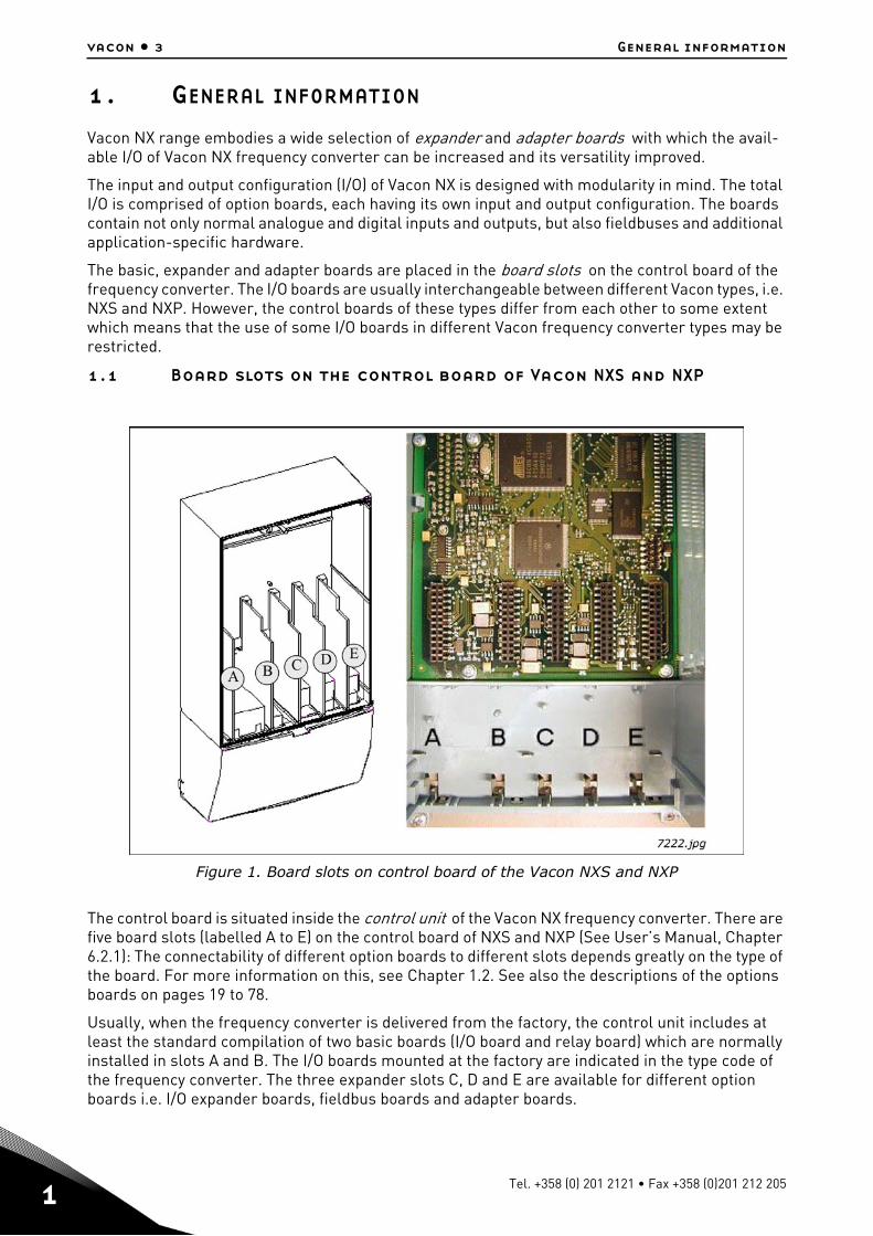
1.1 Board slots on the control board of Vacon NXS and NXP
Figure 1. Board slots on control board of the Vacon NXS and NXP
The control board is situated inside the control unit of the Vacon NX frequency converter. There are five board slots (labelled A to E) on the control board of NXS and NXP (See User’s Manual, Chapter 6.2.1): The connectability of different option boards to different slots depends greatly on the type of the board. For more information on this, see Chapter 1.2. See also the descriptions of the options boards on pages 19 to 78.
Usually, when the frequency converter is delivered from the factory, the control unit includes at least the standard compilation of two basic boards (I/O board and relay board) which are normally installed in slots A and B. The I/O boards mounted at the factory are indicated in the type code of the frequency converter. The three expander slots C, D and E are available for different option boards i.e. I/O expander boards, fieldbus boards and adapter boards.
Tel. +358 (0) 201 2121 • Fax +358 (0)201 212 205
General information vacon • 4
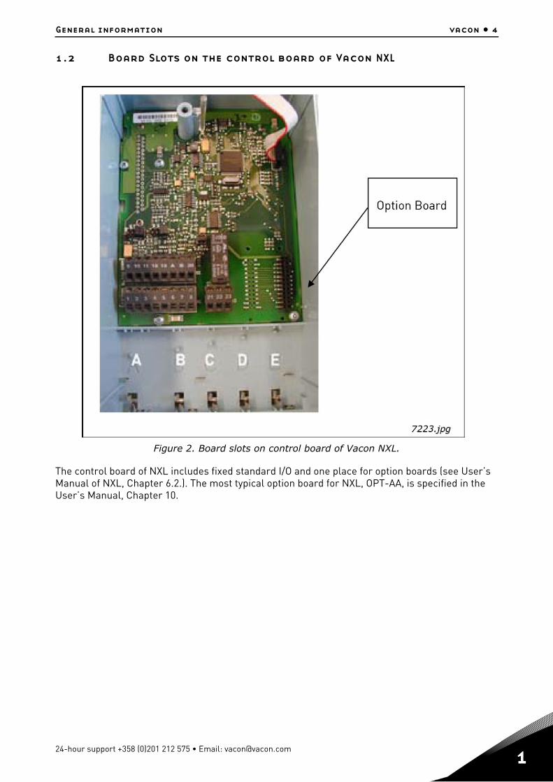
1.2 Board Slots on the control board of Vacon NXL
Figure 2. Board slots on control board of Vacon NXL.
The control board of NXL includes fixed standard I/O and one place for option boards (see User’s Manual of NXL, Chapter 6.2.). The most typical option board for NXL, OPT-AA, is specified in the User’s Manual, Chapter 10.
24-hour support +358 (0)201 212 575 • Email: [email protected]
1
vacon • 5 General information
1.3 Option board types
The Vacon option boards are divided in four groups according to their characteristics: types A, B, C and D. Short descriptions of the types below:
OPTA_
• Basic boards used for basic I/O (NXS, NXP); normally pre-installed at the factory.• This board type uses slots A, B or C.
See pages 18 to 50 for a detailed presentation of the boards of this type. See also the principle dia-gram on the options boards and their equipment on page 80.
OPTB_
• Option boards used for I/O expansion.• Normally pluggable into slots B, C, D and E.
See pages 54 to 63 for a detailed presentation of the boards of this type. See also the principle dia-gram on the options boards and their equipment on page 80.
OPTC_
• Fieldbus boards (e.g. Profibus or Modbus).• These boards are connected to slots D and E.
See a separate manual on each individual Fieldbus Board. Ask factory or your nearest distributor for more information.
OPTD_
• Adapter boards• Boards with fiber optic adapters, e.g. System Bus Fiber Optic Adapter Board.• Connect the adapter boards to slots D and E (see however page 76).
See pages 67 to 78 for a detailed presentation of the boards of this type. See also the principle dia-gram on the option boards and their equipment on page 80.
Tel. +358 (0) 201 2121 • Fax +358 (0)201 212 205

General information vacon • 6
1.4 Technical data
The data in the table below applies to the inputs and outputs on all basic and expander boards.
Table 1. Technical data
Safety (all boards)Comply with EN50178, C-UL and EN60204-1
Inputs/outputs galvanically isolated; Isolation voltage rate 500V
Input/output type Specification
Analogue inputs (AI), voltage 0…±10V, Ri 200 k, single-ended;Resolution 10 bits/0.1%, accuracy ±1% of the full display(–10…+10V joystick control)
Analogue inputs (AI), current 0(4)…20mA, Ri = 250, differentialResolution 10 bits/0.1%, accuracy ±1% of the full display
Digital inputs (DI), DC voltage controlled 24V: "0"10V, "1"18V, Ri > 5k
Digital inputs (DI), AC voltage controlled Control voltage 42…240 VAC"0"<33V, "1">35V
Auxiliary voltage (output) (+24V) 24V (±15%), max 250mA (total summarized load from ext. +24V outputs, max. 150 mA from one board.
Auxiliary voltage (input) (ext. +24V) 24VDC (±10%, max. ripple voltage 100mV RMS), max. 1A.In special applications where PLC type functions are included in the control unit the input can be used as external auxiliary power supply for control boards as well as I/O boards.
Reference voltage (output) (+10Vref) 10V – 0% – +2%, max. 10mA
Analogue output (AO), current (mA) 0(4)…20mA, RL<500, resolution 10 bits/0.1%, accuracy ±2%
Analogue output (AO), voltage (V) 0(2)…10V, RL 1k, resolution 10 bits, accuracy ±2%
Relay outputs (RO) Switching capacity
Max. continuous loadMin.switching load:
24VDC/8A250VAC/8A125VDC/0.4A2A rms5V/10mA
Thermistor input (TI) Rtrip = 4.7k (PTC type)
Encoder control voltage (+5V/+12V/ +15V/+24V)
See OPTA4, OPTA5, OPTA7, OPTAE and OPTBB technical data
Encoder connections (inputs, outputs) See OPTA4, OPTA5, OPTA7, OPTAE and OPTBB technical data
Environment (all boards)
Ambient operating temperature –10…55°C
Storing temperature –40…60°C
Humidity <95%, no condensation allowed
Altitude Ma 1000m
Vibration 0,5 G at 9…200 Hz
24-hour support +358 (0)201 212 575 • Email: [email protected]
1
vacon • 7 General information
1.4.1 Isolation
The control connections are isolated from the mains potential and the I/O ground is connected directly to the frame of the frequency converter. Digital inputs and relay outputs are isolated from the I/O ground. For digital input arrangements, see Chapter Digital input signal conversions on page 8.
1.4.2 Analogue inputs (mA/V)
Analogue inputs of I/O boards can be used as either current inputs or voltage inputs (see detailed description of each board). The signal type is selected with a jumper block on the board. In case the voltage type input is used you still have to define the voltage range with another jumper block. The factory default value for the analogue signal type is given in the description of the board. For de-tailed information, see the description of the board in question.
1.4.3 Analogue outputs (mA/V)
In the same way as in the analogue inputs, the output signal type (current/voltage) can be selected with jumper except for some expander boards with analogue outputs used only with current sig-nals.
1.4.4 Control voltage (+24V/EXT +24V)
The control voltage output +24V/EXT+24V can be used in two ways. Typically, the +24V control volt-age is wired to digital inputs through an external switch. The control voltage can also be used to power-up external equipment, such as encoders and auxiliary relays.
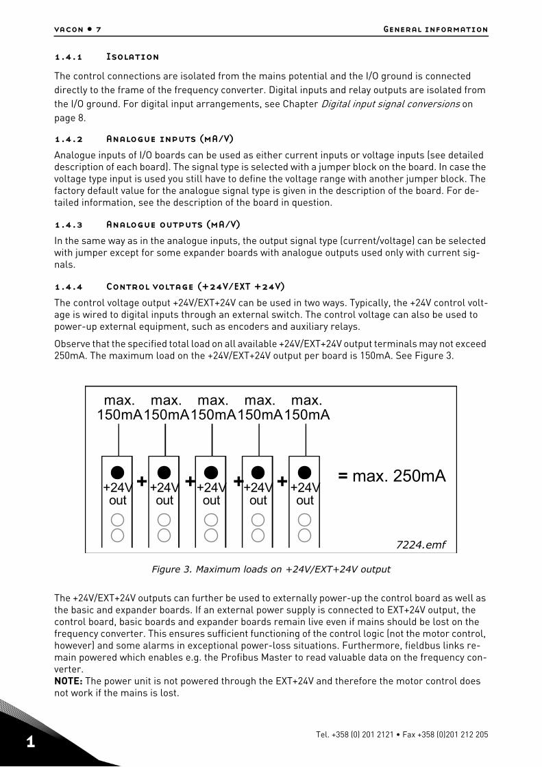
Observe that the specified total load on all available +24V/EXT+24V output terminals may not exceed 250mA. The maximum load on the +24V/EXT+24V output per board is 150mA. See Figure 3.
Figure 3. Maximum loads on +24V/EXT+24V output
The +24V/EXT+24V outputs can further be used to externally power-up the control board as well as the basic and expander boards. If an external power supply is connected to EXT+24V output, the control board, basic boards and expander boards remain live even if mains should be lost on the frequency converter. This ensures sufficient functioning of the control logic (not the motor control, however) and some alarms in exceptional power-loss situations. Furthermore, fieldbus links re-main powered which enables e.g. the Profibus Master to read valuable data on the frequency con-verter. NOTE: The power unit is not powered through the EXT+24V and therefore the motor control does not work if the mains is lost.
+24Vout
+24Vout
+24Vout
+24Vout
+24Vout
+ + + + = max. 250mA
max.150mA
max.150mA
max.150mA
max.150mA
max.150mA
7224.emf
Tel. +358 (0) 201 2121 • Fax +358 (0)201 212 205
General information vacon • 8
Requirements for an external power back-up:
- output voltage +24DC±10%, max. ripple voltage 100mV RMS- max. current 1A- 1A external fuse (no internal short-circuit protection on the control board
NOTE: Analogue outputs and inputs do not work with only +24V supplied to the control unit.
If there is a +24V/EXT+24V output on the board it is short-circuit protected locally. Should one of the +24V/EXT+24V outputs short-circuit, the others would remain powered because of the local protec-tion.
1.4.5 Digital input signal conversion
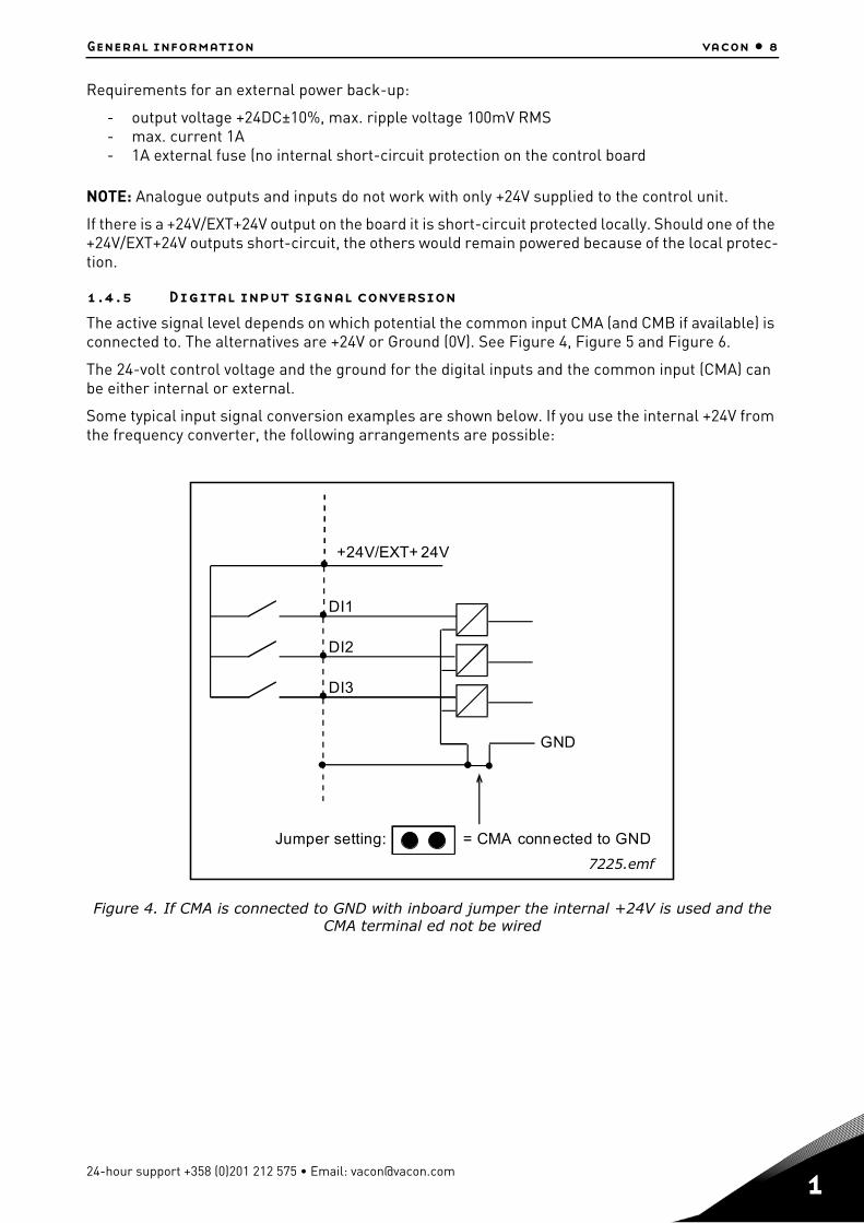
The active signal level depends on which potential the common input CMA (and CMB if available) is connected to. The alternatives are +24V or Ground (0V). See Figure 4, Figure 5 and Figure 6.
The 24-volt control voltage and the ground for the digital inputs and the common input (CMA) can be either internal or external.
Some typical input signal conversion examples are shown below. If you use the internal +24V from the frequency converter, the following arrangements are possible:
Figure 4. If CMA is connected to GND with inboard jumper the internal +24V is used and the CMA terminal ed not be wired
+24V/EXT+ 24V
DI1
DI2
DI3
GND
Jumper setting: = CMA connected to GND
7225.emf
24-hour support +358 (0)201 212 575 • Email: [email protected]
1
vacon • 9 General information
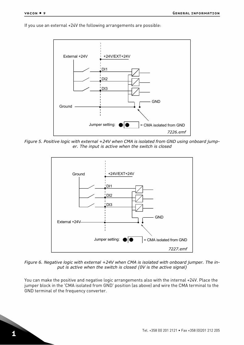
If you use an external +24V the following arrangements are possible:
Figure 5. Positive logic with external +24V when CMA is isolated from GND using onboard jump-er. The input is active when the switch is closed
Figure 6. Negative logic with external +24V when CMA is isolated with onboard jumper. The in-put is active when the switch is closed (0V is the active signal)
You can make the positive and negative logic arrangements also with the internal +24V. Place the jumper block in the 'CMA isolated from GND' position (as above) and wire the CMA terminal to the GND terminal of the frequency converter.
+24V/EXT+24V
DI1
DI2
DI3
GND
Jumper setting: = CMA isolated from GND
Ground
External +24V
7226.emf
+24V/EXT+24V
DI1
DI2
DI3
GND
Jumper setting: = CMA isolated from GND
External +24V
Ground
7227.emf
Tel. +358 (0) 201 2121 • Fax +358 (0)201 212 205

General information vacon • 10
1.5 Hardware protections
1.5.1 Terminal block coding
In order to avoid incorrect connections of terminal blocks to boards, some terminal blocks as well as related terminal connectors on the board are uniquely coded. For more information, see the de-scription of the individual board.
1.5.2 Board slot guides and allowed slots
You cannot mount an option board into any slot.Table 43 and Table 44 show which slots are allowed for which option boards. For reasons of safety, slots A and B are protected in hardware against mounting of unallowed boards. As regards mounting of unallowed boards into slots C, D and E, the boards just will not work, there is no danger of health or equipment damage.
Figure 7. Board guide to prevent incorrect mountings
24-hour support +358 (0)201 212 575 • Email: [email protected]
1
vacon • 11 General information
1.6 Type identification number
NOTE: This information is relevant only for special applications designers using the Vacon NC1131-3 engineering tool.
Each Vacon OPTxx board has a unique type designation code. Besides the type designation code, each board has a unique Type identification number which is used by the system program to identify which board is plugged into which board slot. The system program and the application use the Type ID also to establish the needed connections in order to achieve the desired functionality of the avail-able I/O boards in the control unit. The ID code is loaded in the memory of the board.
1.7 Defining functions to inputs and outputs
How to connect functions and the available I/O depends on the application you use. The Vacon All in One Application Package includes seven applications: Basic Application, Standard Application, PID Control Application, Multi-Step Speed Control Application, Local/Remote Control Application, Pump and Fan Control Application with Autochange and Multipurpose Control Application (see Ap-plication Manuals). All but two applications of these use the conventional Vacon method to connect functions and the I/O. In the Function to Terminal Programming Method (FTT), you have a fixed in-put or output that you define a certain function for. The mentioned two applications, Pump and Fan Control and Multipurpose Control Application, however, use the Terminal to Function Program-ming Method (TTF) in which the programming process is carried out the other way round: Func-tions appear as parameters which the operator defines a certain input/output for.
Connecting a certain input or output to a certain function (parameter) is done by giving the param-eter an appropriate value, the address code. The code is formed of the Board slot on the Vacon NX control board (see page 3 and 4) and the respective input/output number. See below.
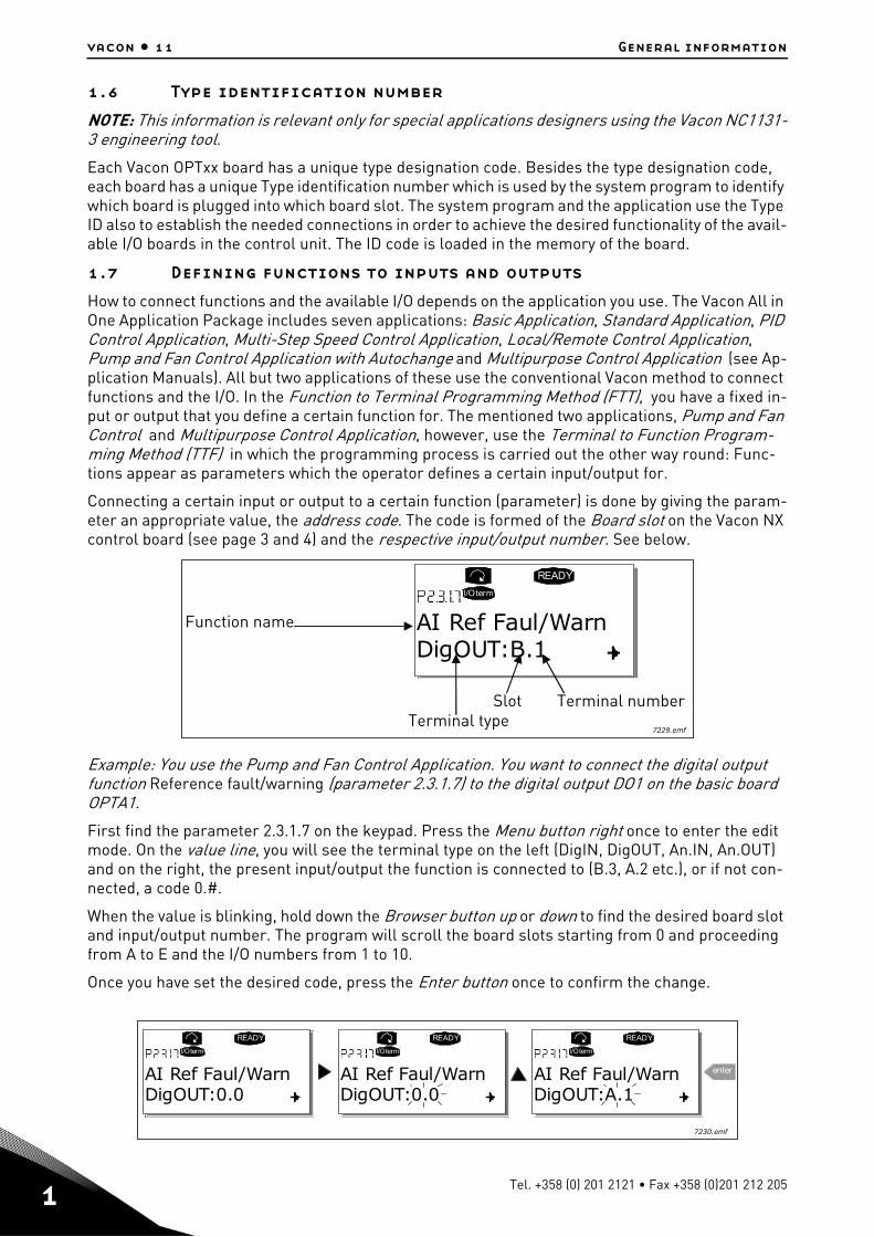
Example: You use the Pump and Fan Control Application. You want to connect the digital output function Reference fault/warning (parameter 2.3.1.7) to the digital output DO1 on the basic board OPTA1.
First find the parameter 2.3.1.7 on the keypad. Press the Menu button right once to enter the edit mode. On the value line, you will see the terminal type on the left (DigIN, DigOUT, An.IN, An.OUT) and on the right, the present input/output the function is connected to (B.3, A.2 etc.), or if not con-nected, a code 0.#.
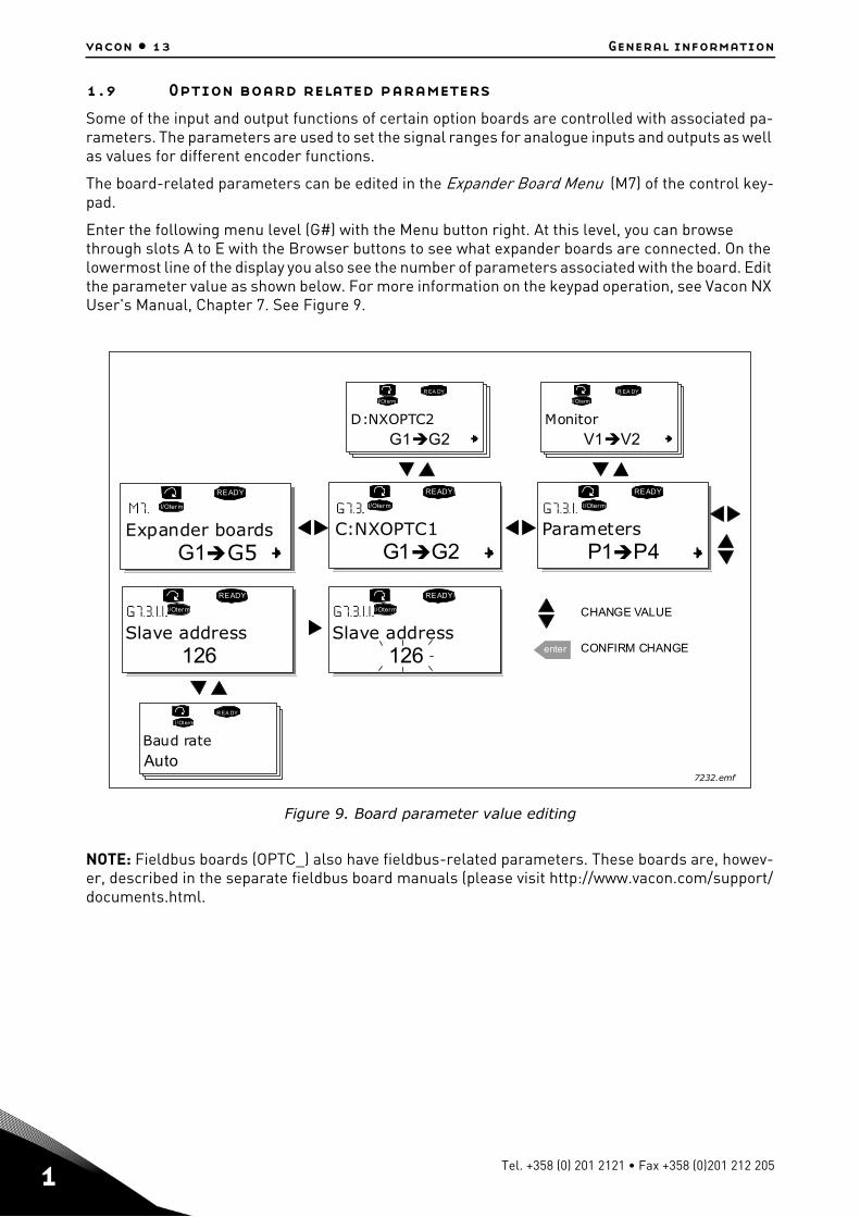
When the value is blinking, hold down the Browser button up or down to find the desired board slot and input/output number. The program will scroll the board slots starting from 0 and proceeding from A to E and the I/O numbers from 1 to 10.
Once you have set the desired code, press the Enter button once to confirm the change.
READY
I/Oterm
DigOUT:B.1AI Ref Faul/WarnFunction name
rebmunlanimreTtolSepytlanimreT
7229.emf
READY
I/Oterm
DigOUT:0.0
READY
I/Oterm
DigOUT:0.0
READY
I/Oterm
DigOUT:A.1
enterAI Ref Faul/Warn AI Ref Faul/Warn AI Ref Faul/Warn
7230.emf
Tel. +358 (0) 201 2121 • Fax +358 (0)201 212 205

General information vacon • 12
1.8 Defining a terminal for a certain function with NCDrive pro-
gramming tool
If you use the NCDrive Programming Tool for parametrizing you will have to establish the connec-tion between the function and input/output in the same way as with the control panel. Just pick the address code from the drop-down menu in the Value column (see Figure 8 below).
Figure 8. Screenshot of NCDrive programming tool; Entering the address code
NOTE: The inputs, unlike the outputs, cannot be changed in RUN state.
Be ABSOLUTELY sure not to connect two functions to one and same output in order to avoid function overruns and to ensure flawless operation.
24-hour support +358 (0)201 212 575 • Email: [email protected]
1
vacon • 13 General information
1.9 Option board related parameters
Some of the input and output functions of certain option boards are controlled with associated pa-rameters. The parameters are used to set the signal ranges for analogue inputs and outputs as well as values for different encoder functions.
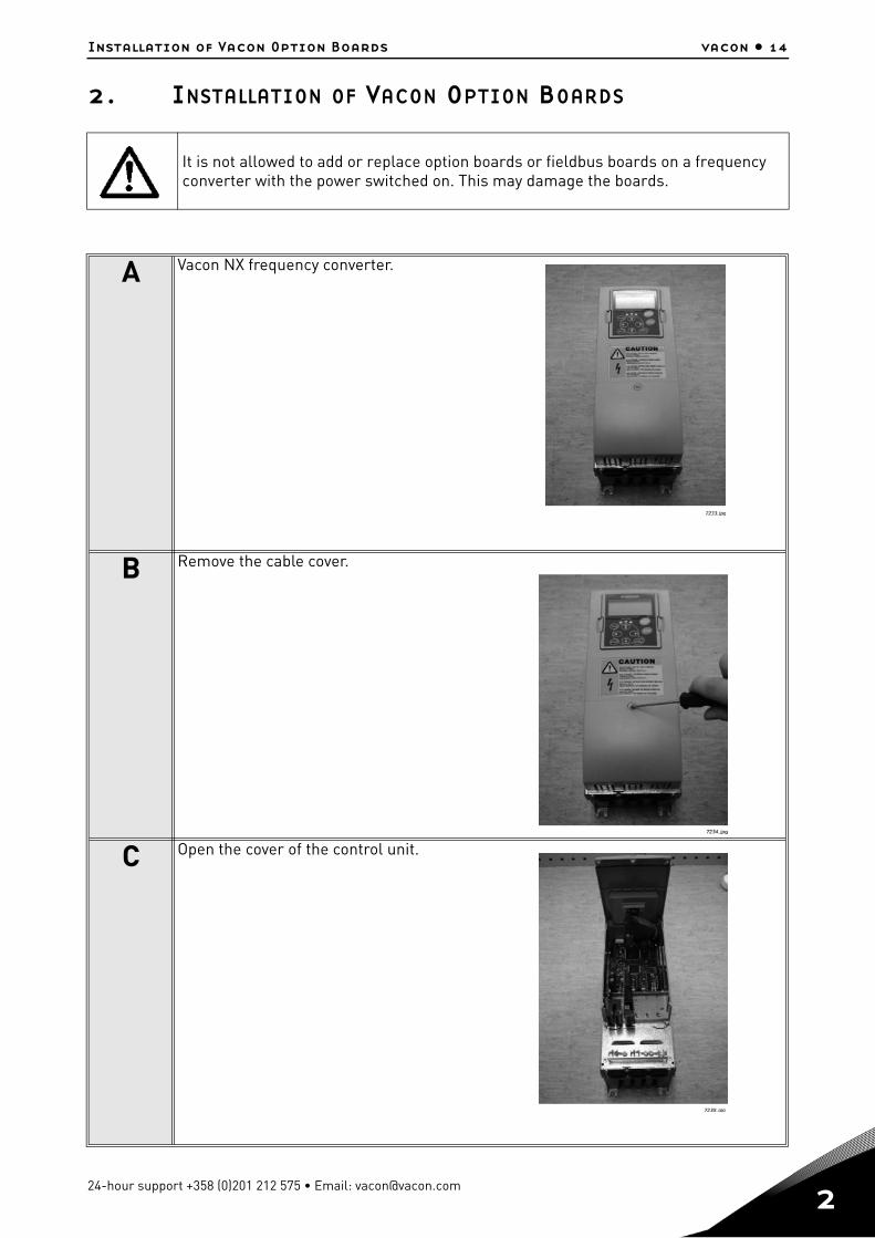
The board-related parameters can be edited in the Expander Board Menu (M7) of the control key-pad.
Enter the following menu level (G#) with the Menu button right. At this level, you can browse through slots A to E with the Browser buttons to see what expander boards are connected. On the lowermost line of the display you also see the number of parameters associated with the board. Edit the parameter value as shown below. For more information on the keypad operation, see Vacon NX User's Manual, Chapter 7. See Figure 9.
Figure 9. Board parameter value editing
NOTE: Fieldbus boards (OPTC_) also have fieldbus-related parameters. These boards are, howev-er, described in the separate fieldbus board manuals (please visit http://www.vacon.com/support/documents.html.
G1G5
READY
I/Oterm
C:NXOPTC1
READY
I/Oterm
G1G2
READY
I/Oterm
READY
I/Oterm
enter
P1P4
D:NXOPTC2
R EA DY
I/Oterm
G1G2
R EA DY
I/Oterm
V1V2
READY
I/Oterm
R EA DY
I/Oterm
Expander boards Parameters
Slave address126
CHANGE VALUE
CONFIRM CHANGESlave address
126
Baud rateAuto
Monitor
7232.emf
Tel. +358 (0) 201 2121 • Fax +358 (0)201 212 205
Installation of Vacon Option Boards vacon • 14
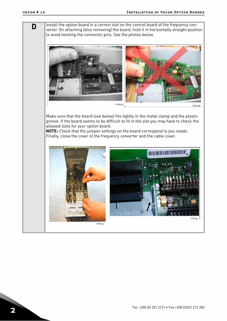
2. INSTALLATION OF VACON OPTION BOARDS
It is not allowed to add or replace option boards or fieldbus boards on a frequency converter with the power switched on. This may damage the boards.
A Vacon NX frequency converter.
B Remove the cable cover.
C Open the cover of the control unit.
24-hour support +358 (0)201 212 575 • Email: [email protected]
2
vacon • 15 Installation of Vacon Option Boards
D Install the option board in a correct slot on the control board of the frequency con-verter. On attaching (also removing) the board, hold it in horizontally straight position to avoid twisting the connector pins. See the photos below.
Make sure that the board (see below) fits tightly in the metal clamp and the plastic groove. If the board seems to be difficult to fit in the slot you may have to check the allowed slots for your option board.NOTE: Check that the jumper settings on the board correspond to you needs.Finally, close the cover of the frequency converter and the cable cover.
Tel. +358 (0) 201 2121 • Fax +358 (0)201 212 205
Installation of Vacon Option Boards vacon • 16
2.1 Control cables
The control cables used shall be at least 0.5mm2 screened multicore cables. The maximum termi-nal wire size is 2.5mm2 for the relay terminals and 1.5 mm2 for other terminals.
Find the tightening torques of the option board terminals in the table below.
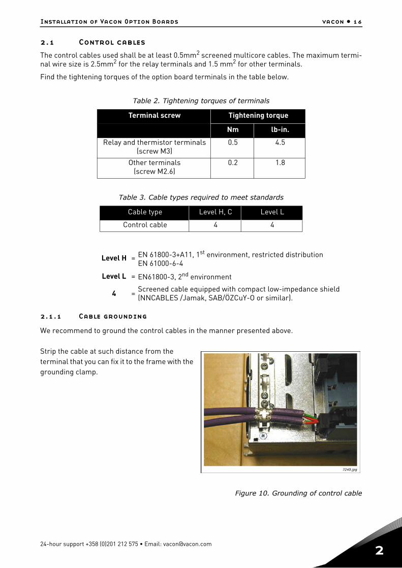
2.1.1 Cable grounding
We recommend to ground the control cables in the manner presented above.
Strip the cable at such distance from the terminal that you can fix it to the frame with the grounding clamp.
Figure 10. Grounding of control cable
Table 2. Tightening torques of terminals
Terminal screw Tightening torque
Nm lb-in.
Relay and thermistor terminals(screw M3)
0.5 4.5
Other terminals(screw M2.6)
0.2 1.8
Table 3. Cable types required to meet standards
Cable type Level H, C Level L
Control cable 4 4
Level H = EN 61800-3+A11, 1st environment, restricted distributionEN 61000-6-4
Level L = EN61800-3, 2nd environment
4 = Screened cable equipped with compact low-impedance shield (NNCABLES /Jamak, SAB/ÖZCuY-O or similar).
24-hour support +358 (0)201 212 575 • Email: [email protected]
2
vacon • 17 Installation of Vacon Option Boards
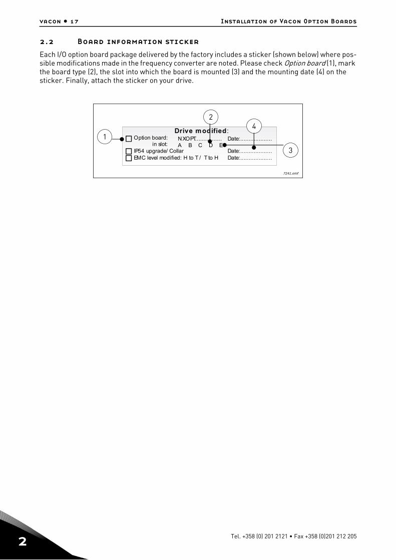
2.2 Board information sticker
Each I/O option board package delivered by the factory includes a sticker (shown below) where pos-sible modifications made in the frequency converter are noted. Please check Option board (1), mark the board type (2), the slot into which the board is mounted (3) and the mounting date (4) on the sticker. Finally, attach the sticker on your drive.
Drive modified:Option board: NXOPT................
IP54 upgrade/ Collarin slot:
Date:...................
A B C D E
EMC level modified: H to T / T to HDate:...................
Date:...................
3
24
1
7241.emf
Tel. +358 (0) 201 2121 • Fax +358 (0)201 212 205
Descriptions of Vacon option boards vacon • 18
3. DESCRIPTIONS OF VACON OPTION BOARDS
3.1 Basic boards OPTA_
• Basic boards used for basic I/O; normally pre-installed at the factory.• This board type uses slots A, B and C.
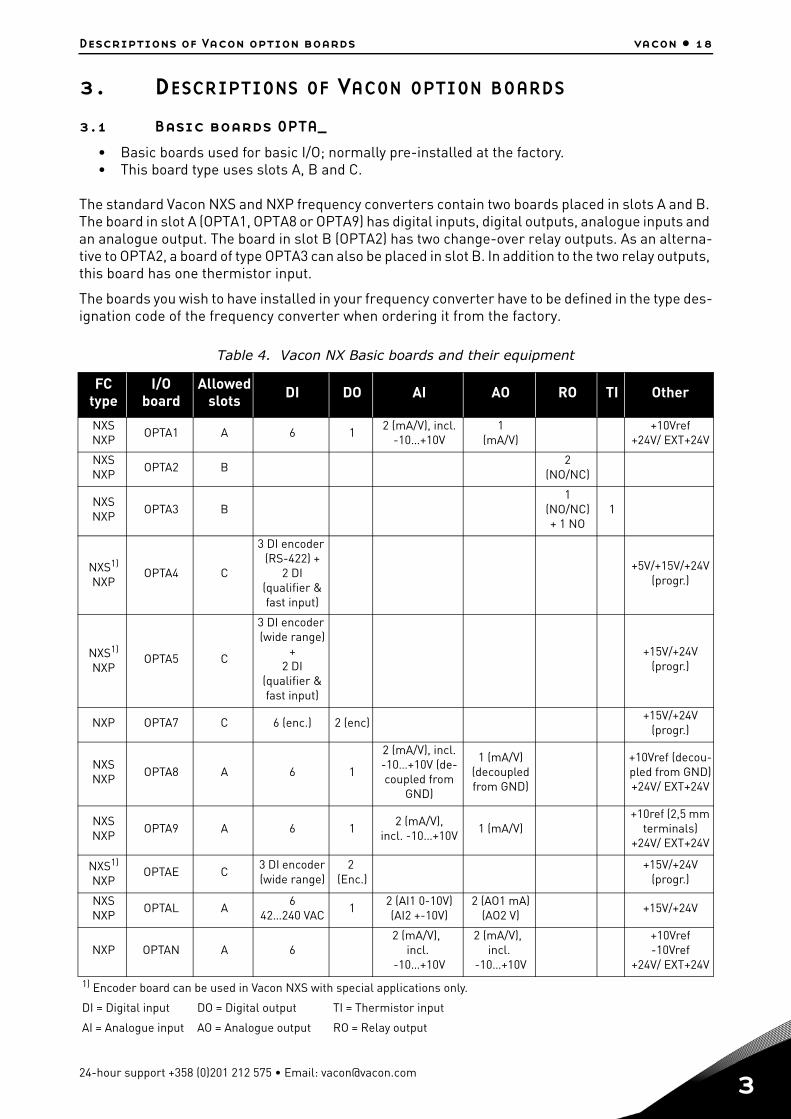
The standard Vacon NXS and NXP frequency converters contain two boards placed in slots A and B. The board in slot A (OPTA1, OPTA8 or OPTA9) has digital inputs, digital outputs, analogue inputs and an analogue output. The board in slot B (OPTA2) has two change-over relay outputs. As an alterna-tive to OPTA2, a board of type OPTA3 can also be placed in slot B. In addition to the two relay outputs, this board has one thermistor input.
The boards you wish to have installed in your frequency converter have to be defined in the type des-ignation code of the frequency converter when ordering it from the factory.
Table 4. Vacon NX Basic boards and their equipment
FC type
I/O board
Allowed slots DI DO AI AO RO TI Other
NXSNXP
OPTA1 A 6 12 (mA/V), incl.
-10…+10V1
(mA/V)+10Vref
+24V/ EXT+24V
NXSNXP
OPTA2 B2
(NO/NC)
NXSNXP
OPTA3 B1
(NO/NC)+ 1 NO
1
NXS1)
NXPOPTA4 C
3 DI encoder (RS-422) +
2 DI(qualifier & fast input)
+5V/+15V/+24V (progr.)
NXS1)
NXPOPTA5 C
3 DI encoder (wide range)
+2 DI
(qualifier & fast input)
+15V/+24V (progr.)
NXP OPTA7 C 6 (enc.) 2 (enc)+15V/+24V
(progr.)
NXSNXP
OPTA8 A 6 1
2 (mA/V), incl.-10…+10V (de-coupled from
GND)
1 (mA/V)(decoupled from GND)
+10Vref (decou-pled from GND)+24V/ EXT+24V
NXSNXP
OPTA9 A 6 12 (mA/V),
incl. -10…+10V1 (mA/V)
+10ref (2,5 mm terminals)
+24V/ EXT+24V
NXS1)
NXPOPTAE C
3 DI encoder (wide range)
2 (Enc.)
+15V/+24V (progr.)
NXSNXP
OPTAL A6
42…240 VAC1
2 (AI1 0-10V)(AI2 +-10V)
2 (AO1 mA)(AO2 V)
+15V/+24V
NXP OPTAN A 62 (mA/V),
incl. -10…+10V
2 (mA/V), incl.
-10…+10V
+10Vref-10Vref
+24V/ EXT+24V
1) Encoder board can be used in Vacon NXS with special applications only.
DI = Digital input DO = Digital output TI = Thermistor input
AI = Analogue input AO = Analogue output RO = Relay output
24-hour support +358 (0)201 212 575 • Email: [email protected]
3
vacon • 19 Descriptions of Vacon option boards
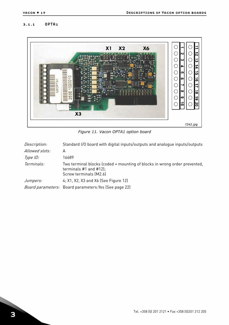
3.1.1 OPTA1
Figure 11. Vacon OPTA1 option board
Description: Standard I/O board with digital inputs/outputs and analogue inputs/outputs
Allowed slots: A
Type ID: 16689
Terminals: Two terminal blocks (coded = mounting of blocks in wrong order prevented, terminals #1 and #12); Screw terminals (M2.6)
Jumpers: 4; X1, X2, X3 and X6 (See Figure 12)
Board parameters: Board parameters:Yes (See page 22)
Tel. +358 (0) 201 2121 • Fax +358 (0)201 212 205
Descriptions of Vacon option boards vacon • 20
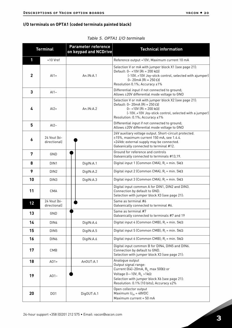
I/O terminals on OPTA1 (coded terminals painted black)
Table 5. OPTA1 I/O terminals
Terminal Parameter referenceon keypad and NCDrive Technical information
1 +10 Vref Reference output +10V; Maximum current 10 mA
2 AI1+ An.IN:A.1
Selection V or mA with jumper block X1 (see page 21):Default: 0– +10V (Ri = 200 k) (-10V..+10V Joy-stick control, selected with ajumper) 0– 20mA (Ri = 250 )Resolution 0.1%; Accuracy ±1%
3 AI1–Differential input if not connected to ground; Allows 20V differential mode voltage to GND
4 AI2+ An.IN:A.2
Selection V or mA with jumper block X2 (see page 21):Default: 0– 20mA (Ri = 250 ) 0– +10V (Ri = 200 k) (-10V..+10V Joy-stick control, selected with a jumper)Resolution: 0.1%; Accuracy ±1%
5 AI2–Differential input if not connected to ground; Allows 20V differential mode voltage to GND
6 24 Vout (bi-directional)
24V auxiliary voltage output. Short-circuit protected.15%, maximum current 150 mA, see 1.4.4.+24Vdc external supply may be connected.Galvanically connected to terminal #12.
7 GNDGround for reference and controlsGalvanically connected to terminals #13,19.
8 DIN1 DigIN:A.1 Digital input 1 (Common CMA); Ri = min. 5k
9 DIN2 DigIN:A.2 Digital input 2 (Common CMA); Ri = min. 5k
10 DIN3 DigIN:A.3 Digital input 3 (Common CMA); Ri = min. 5k
11 CMADigital input common A for DIN1, DIN2 and DIN3.Connection by default to GND.Selection with jumper block X3 (see page 21):
12 24 Vout (bi-directional)
Same as terminal #6Galvanically connected to terminal #6.
13 GNDSame as terminal #7Galvanically connected to terminals #7 and 19
14 DIN4 DigIN:A.4 Digital input 4 (Common CMB); Ri = min. 5k
15 DIN5 DigIN:A.5 Digital input 5 (Common CMB); Ri = min. 5k
16 DIN6 DigIN:A.6 Digital input 6 (Common CMB); Ri = min. 5k
17 CMBDigital input common B for DIN4, DIN5 and DIN6.Connection by default to GND.Selection with jumper block X3 (see page 21):
18 AO1+ AnOUT:A.1 Analogue outputOutput signal range:Current 0(4)–20mA, RL max 500 orVoltage 0—10V, RL >1kSelection with jumper block X6 (see page 21):Resolution: 0.1% (10 bits); Accuracy ±2%
19 AO1–
20 DO1 DigOUT:A.1Open collector outputMaximum Uin = 48VDCMaximum current = 50 mA
24-hour support +358 (0)201 212 575 • Email: [email protected]

3
vacon • 21 Descriptions of Vacon option boards
Jumper selections
There are four jumper blocks on the OPTA1 board. The factory defaults and other available jumper selections are presented below.
Figure 12. Jumper block selection on OPTA1
A B C D
A B C D
A B C D
A B C D
A B C D
A B C D
A B C D
A B C D
A B C D
A B C D
Jumper block X1:AI1 mode
AI1 mode: Voltage input; 0...10V
AI1 mode: Voltage input; 0...10V (differential)
AI1 mode: Voltage input; -10...10V
Jumper block X2:AI2 mode
AI2 mode: 0...20mA; Current input
AI2 mode: Voltage input; 0...10V
AI2 mode: Voltage input; 0...10V (differential)
AI2 mode: Voltage input; -10 ...10V
Jumper block X3:CM A and CM B grounding
CMB connected to GN DCMA connected to GN D
CMB isolated from GN DCMA isolated from GN D
CMB and CMAinternally connected together,isolated from GN D
= Factory default
Jumper block X6:AO1 mode
AO1 mode: 0...20mA; Current output
AO1 mode: Voltage output; 0...10V
AI1 mode: 0...20mA; Current input
7243.emf
Tel. +358 (0) 201 2121 • Fax +358 (0)201 212 205
Descriptions of Vacon option boards vacon • 22
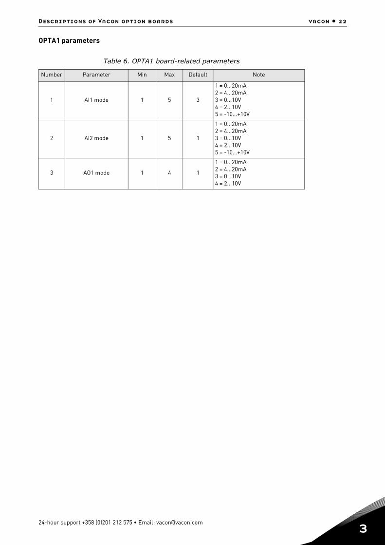
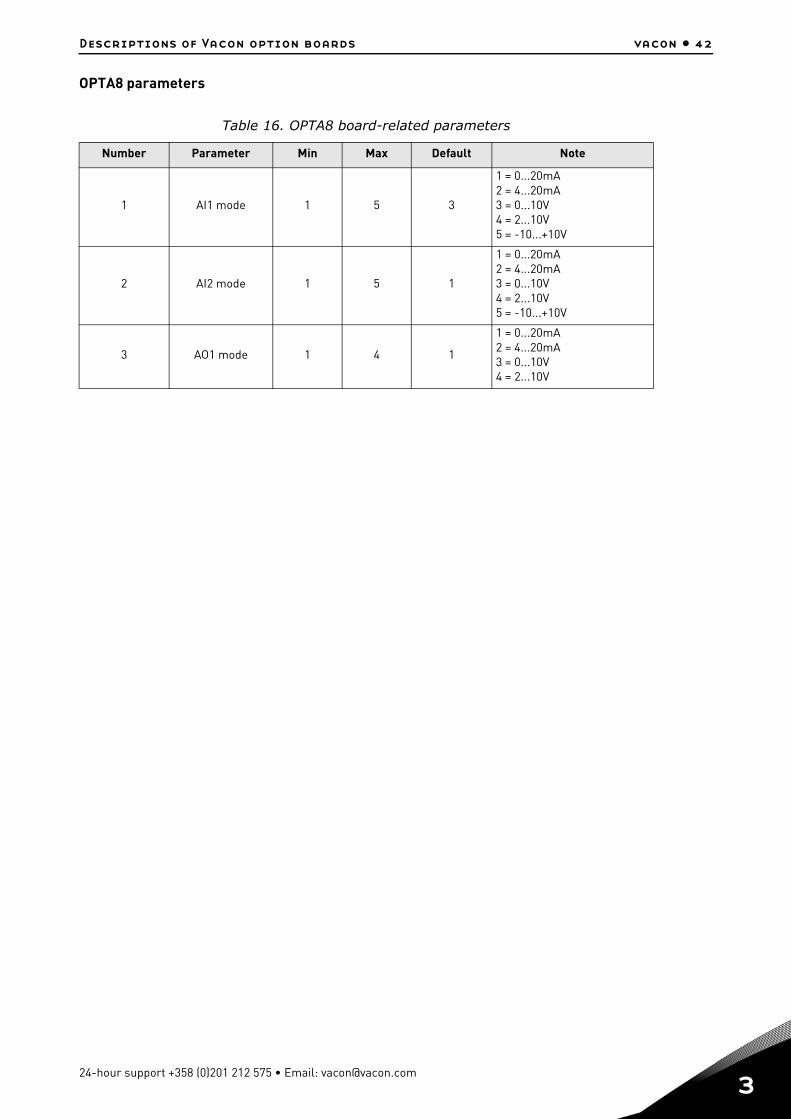
OPTA1 parameters
Table 6. OPTA1 board-related parameters
Number Parameter Min Max Default Note
1 AI1 mode 1 5 3
1 = 0...20mA2 = 4...20mA3 = 0...10V4 = 2...10V5 = -10...+10V
2 AI2 mode 1 5 1
1 = 0...20mA2 = 4...20mA3 = 0...10V4 = 2...10V5 = -10...+10V
3 AO1 mode 1 4 1
1 = 0...20mA2 = 4...20mA3 = 0...10V4 = 2...10V
24-hour support +358 (0)201 212 575 • Email: [email protected]
3
vacon • 23 Descriptions of Vacon option boards
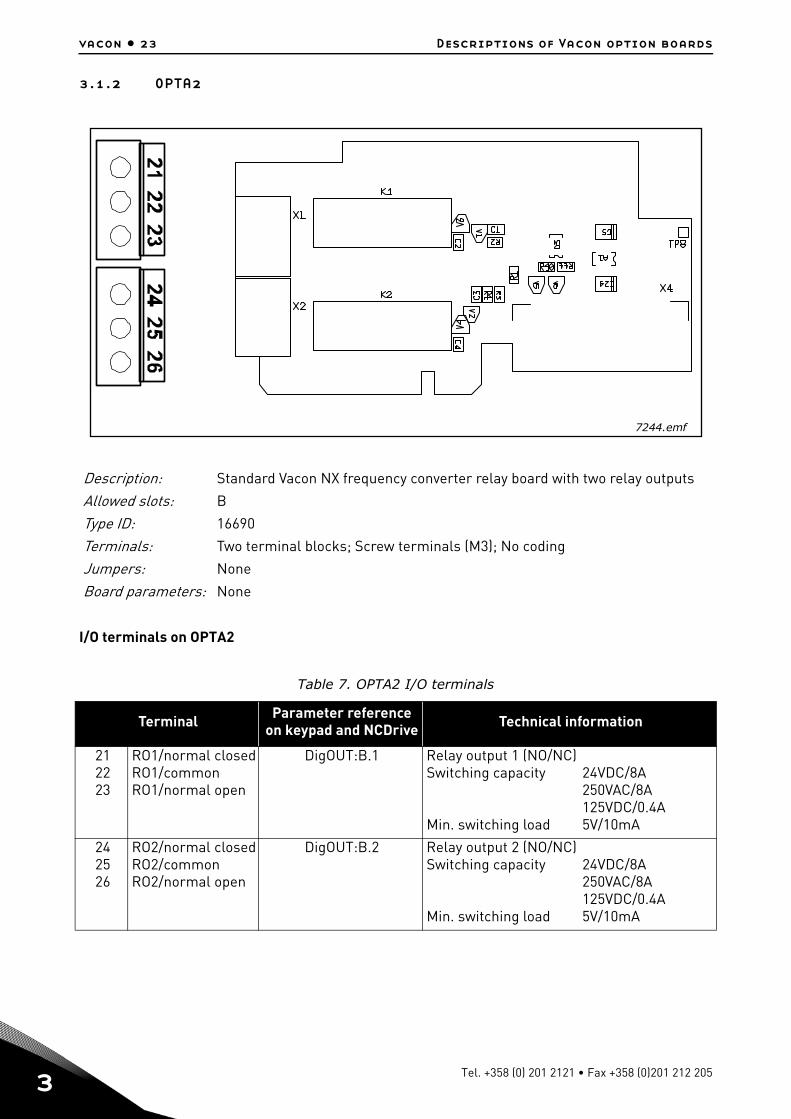
3.1.2 OPTA2
I/O terminals on OPTA2
Description: Standard Vacon NX frequency converter relay board with two relay outputs
Allowed slots: B
Type ID: 16690
Terminals: Two terminal blocks; Screw terminals (M3); No coding
Jumpers: None
Board parameters: None
Table 7. OPTA2 I/O terminals
Terminal Parameter referenceon keypad and NCDrive Technical information
212223
RO1/normal closedRO1/commonRO1/normal open
DigOUT:B.1 Relay output 1 (NO/NC)Switching capacity
Min. switching load
24VDC/8A250VAC/8A125VDC/0.4A5V/10mA
242526
RO2/normal closedRO2/commonRO2/normal open
DigOUT:B.2 Relay output 2 (NO/NC)Switching capacity
Min. switching load
24VDC/8A250VAC/8A125VDC/0.4A5V/10mA
7244.emf
Tel. +358 (0) 201 2121 • Fax +358 (0)201 212 205

Descriptions of Vacon option boards vacon • 24
3.1.3 OPTA3
I/O terminals on OPTA3
Description: Relay board with two relay outputs and one thermistor input for Vacon NX frequency converter
Allowed slots: B
Type ID: 16691
Terminals: Three terminal blocks; Screw terminals (M3); No coding.
Jumpers: None
Board parameters: None
Table 8. OPTA3 I/O terminals
Terminal Parameter referenceon keypad and NCDrive Technical information
212223
RO1/normal closedRO1/commonRO1/normal open
DigOUT:B.1 Relay output 1 (NO/NC)Switching capacity
Min. switching load
24VDC/8A250VAC/8A125VDC/0.4A5V/10mA
2526
RO2/commonRO2/normal open
DigOUT:B.2 Relay output 2 (NO)Switching capacity
Min. switching load
24VDC/8A250VAC/8A125VDC/0.4A5V/10mA
2829
TI1+TI1–
DigIN:B.1 Thermistor input; Rtrip = 4.7 k (PTC)
7245.emf
24-hour support +358 (0)201 212 575 • Email: [email protected]
3
vacon • 25 Descriptions of Vacon option boards
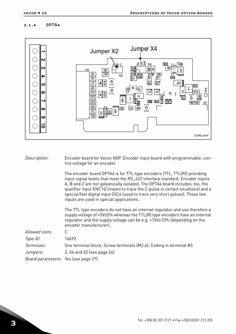
3.1.4 OPTA4
Description: Encoder board for Vacon NXP. Encoder input board with programmable con-trol voltage for an encoder.
The encoder board OPTA4 is for TTL type encoders (TTL, TTL(R)) providing input signal levels that meet the RS_422 interface standard. Encoder inputs A, B and Z are not galvanically isolated. The OPTA4 board includes, too, the qualifier input ENC1Q (meant to trace the Z-pulse in certain situations) and a special/fast digital input DIC4 (used to trace very short pulses). These two inputs are used in special applications.
The TTL type encoders do not have an internal regulator and use therefore a supply voltage of +5V±5% whereas the TTL(R) type encoders have an internal regulator and the supply voltage can be e.g. +15V±10% (depending on the encoder manufacturer).
Allowed slots: C
Type ID: 16692
Terminals: One terminal block; Screw terminals (M2.6); Coding in terminal #3.
Jumpers: 2; X4 and X2 (see page 26)
Board parameters: Yes (see page 27)
Jumper X4Jumper X2
7246.emf
Tel. +358 (0) 201 2121 • Fax +358 (0)201 212 205

Descriptions of Vacon option boards vacon • 26
I/O terminals on OPTA4 (coded terminal painted black)
Technical data:
Jumper selections
On the OPTA4 board, there are two jumper blocks. The jumper X2 is used to define the status of the termination resistor (R=135Ω). The jumper X4 is used to program the control voltage (auxiliary volt-age). The factory default and other available jumper selections are presented below.
Table 9. OPTA4 I/O terminals
Terminal Parameter referenceKeypad/NCDrive Technical information
1 DIC1A+ Pulse input A
2 DIC1A–
3 DIC2B+ Pulse input B; phase shift of 90 degrees compared to Pulse input A
4 DIC2B–
5 DIC3Z+ Pulse input Z; one pulse per revolution
6 DIC3Z–
7 ENC1Q Reserved for future use
8 DIC4 Reserved for future use
9 GND Ground for control and inputs ENC1Q and DIC4
10 +5V/+15V/+24V Control voltage (auxiliary voltage) output to encoder; Output voltage selectable with jumper X4. See chapter 1.4.4.
Encoder control voltage, +5V/+15V/+24V Control voltage selectable with jumper X4.
Encoder input connections, inputs A+, A–, B+, B–, Z+, Z–
Max. input frequency 150kHzInputs A, B and Z are differentialEncoder inputs are RS-422 interface compatibleMax. load per encoder input Ilow = Ihigh 25mA
Qualifier input ENC1Q
Fast digital input DIC4
Max. input frequency 10kHzMin. pulse length 50μsDigital input 24V; Ri>5kDigital input is single-ended; connected to GND
A B C A B C
Jumper block X2:Termination resistor
Termination resistorused
Termination resistornot used
5V
15
V
24
V
= Factory default
5V
15
V
24
V
5V
15
V
24
V
Jumper block X4:Aux ilia ry voltage level
Auxiliary voltage +15V Auxiliary voltage +24VAuxiliary voltage +5V
7247.emf
NOTE: If one encoder is connected to one drive only, the termination resistor on the board must be used. If the encoder is con-nected to several drives, the termination resistor of the last drive must be used.
24-hour support +358 (0)201 212 575 • Email: [email protected]
3
vacon • 27 Descriptions of Vacon option boards
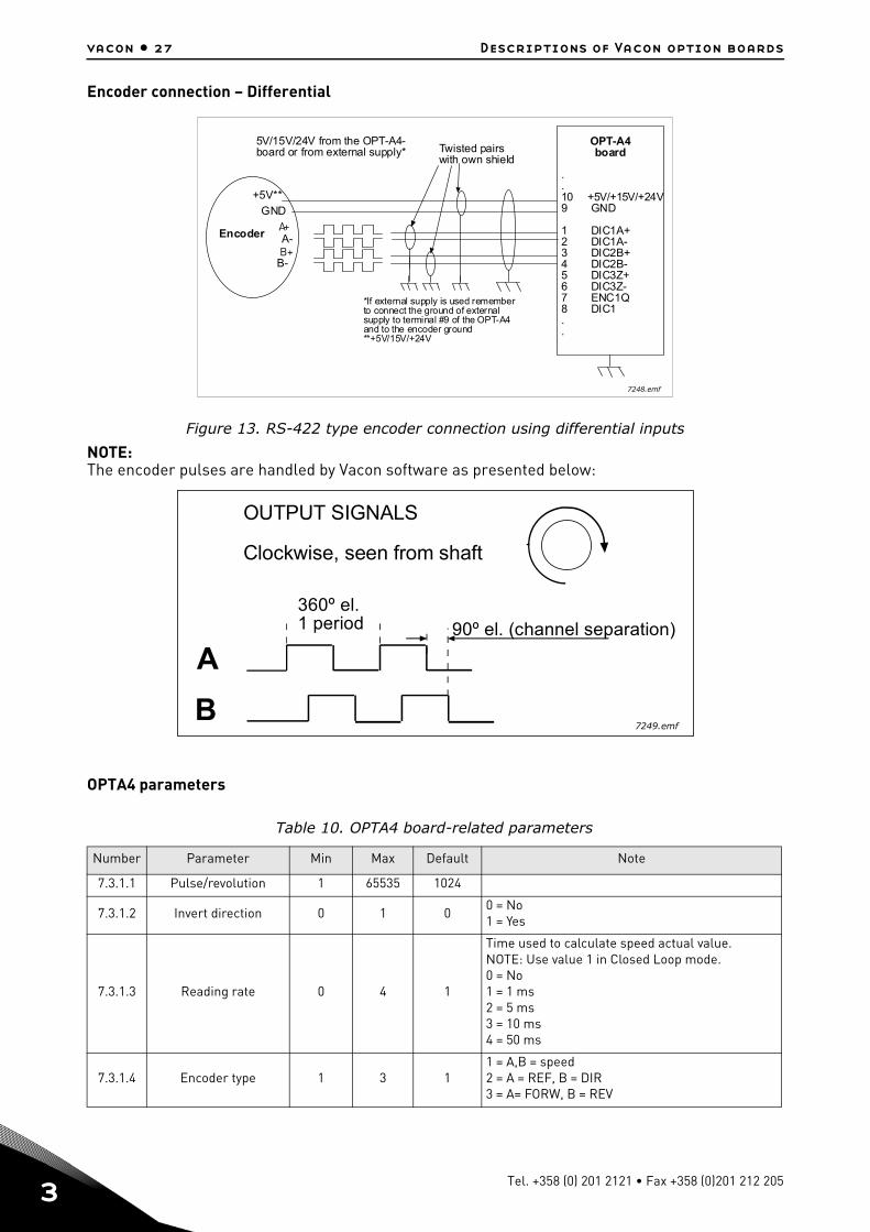
Encoder connection – Differential
Figure 13. RS-422 type encoder connection using differential inputs
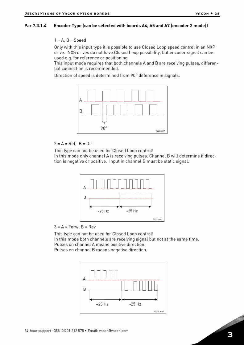
NOTE:The encoder pulses are handled by Vacon software as presented below:
OPTA4 parameters
Table 10. OPTA4 board-related parameters
Number Parameter Min Max Default Note
7.3.1.1 Pulse/revolution 1 65535 1024
7.3.1.2 Invert direction 0 1 00 = No1 = Yes
7.3.1.3 Reading rate 0 4 1
Time used to calculate speed actual value. NOTE: Use value 1 in Closed Loop mode.0 = No1 = 1 ms2 = 5 ms3 = 10 ms4 = 50 ms
7.3.1.4 Encoder type 1 3 11 = A,B = speed2 = A = REF, B = DIR3 = A= FORW, B = REV
GND
A-
B-
+5V**
5V/15V/24V from the OPT-A4-board or from external supply*
OPT-A4board
.
.10 +5V/+15V/+24V9 GND
1 DIC1A+2 DIC1A-3 DIC2B+4 DIC2B-5 DIC3Z+6 DIC3Z-7 ENC1Q8 DIC1..
*If external supply is used rememberto connect the ground of externalsupply to terminal #9 of the OPT-A4and to the encoder ground**+5V/15V/+24V
Encoder
Twisted pairswith own shield
A+
B+
7248.emf
A
OUTPUT SIGNALS
Clockwise, seen from shaft
B
360º el.1 period 90º el. (channel separation)
7249.emf
Tel. +358 (0) 201 2121 • Fax +358 (0)201 212 205
Descriptions of Vacon option boards vacon • 28
Par 7.3.1.4 Encoder Type (can be selected with boards A4, A5 and A7 (encoder 2 mode))
1 = A, B = Speed
Only with this input type it is possible to use Closed Loop speed control in an NXP drive. NXS drives do not have Closed Loop possibility, but encoder signal can be used e.g. for reference or positioning.This input mode requires that both channels A and B are receiving pulses, differen-tial connection is recommended.
Direction of speed is determined from 90° difference in signals.
2 = A = Ref, B = Dir
This type can not be used for Closed Loop control!In this mode only channel A is receiving pulses. Channel B will determine if direc-tion is negative or positive. Input in channel B must be static signal.
3 = A = Forw, B = Rev
This type can not be used for Closed Loop control!In this mode both channels are receiving signal but not at the same time. Pulses on channel A means positive direction.Pulses on channel B means negative direction.
A
B
90°7250.emf
A
B
-25 Hz +25 Hz
7251.emf
A
B
+25 Hz -25 Hz
7252.emf
24-hour support +358 (0)201 212 575 • Email: [email protected]
3
vacon • 29 Descriptions of Vacon option boards
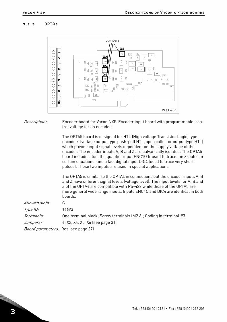
3.1.5 OPTA5
Description: Encoder board for Vacon NXP. Encoder input board with programmable con-trol voltage for an encoder.
The OPTA5 board is designed for HTL (High voltage Transistor Logic) type encoders (voltage output type push-pull HTL, open collector output type HTL) which provide input signal levels dependent on the supply voltage of the encoder. The encoder inputs A, B and Z are galvanically isolated. The OPTA5 board includes, too, the qualifier input ENC1Q (meant to trace the Z-pulse in certain situations) and a fast digital input DIC4 (used to trace very short pulses). These two inputs are used in special applications.
The OPTA5 is similar to the OPTA4 in connections but the encoder inputs A, B and Z have different signal levels (voltage level). The input levels for A, B and Z of the OPTA4 are compatible with RS-422 while those of the OPTA5 are more general wide range inputs. Inputs ENC1Q and DIC4 are identical in both boards.
Allowed slots: C
Type ID: 16693
Terminals: One terminal block; Screw terminals (M2.6); Coding in terminal #3.
Jumpers: 4; X2, X4, X5, X6 (see page 31)
Board parameters: Yes (see page 27)
X4
X2
X5
X6
Jumpers
7253.emf
Tel. +358 (0) 201 2121 • Fax +358 (0)201 212 205
Descriptions of Vacon option boards vacon • 30
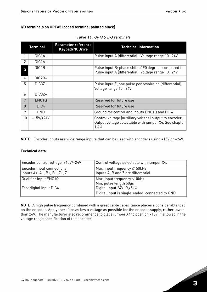
I/O terminals on OPTA5 (coded terminal painted black)
NOTE: Encoder inputs are wide range inputs that can be used with encoders using +15V or +24V.
Technical data:
NOTE: A high pulse frequency combined with a great cable capacitance places a considerable load on the encoder. Apply therefore as low a voltage as possible for the encoder supply, rather lower than 24V. The manufacturer also recommends to place jumper X4 to position +15V, if allowed in the voltage range specification of the encoder.
Table 11. OPTA5 I/O terminals
Terminal Parameter referenceKeypad/NCDrive Technical information
1 DIC1A+ Pulse input A (differential); Voltage range 10…24V
2 DIC1A–
3 DIC2B+ Pulse input B; phase shift of 90 degrees compared to Pulse input A (differential); Voltage range 10…24V
4 DIC2B–
5 DIC3Z+ Pulse input Z; one pulse per revolution (differential);Voltage range 10…24V
6 DIC3Z–
7 ENC1Q Reserved for future use
8 DIC4 Reserved for future use
9 GND Ground for control and inputs ENC1Q and DIC4
10 +15V/+24V Control voltage (auxiliary voltage) output to encoder; Output voltage selectable with jumper X4. See chapter 1.4.4.
Encoder control voltage, +15V/+24V Control voltage selectable with jumper X4.
Encoder input connections, inputs A+, A–, B+, B–, Z+, Z–
Max. input frequency 150kHzInputs A, B and Z are differential
Qualifier input ENC1Q
Fast digital input DIC4
Max. input frequency 10kHzMin. pulse length 50μsDigital input 24V; Ri>5kDigital input is single-ended; connected to GND
24-hour support +358 (0)201 212 575 • Email: [email protected]
3
vacon • 31 Descriptions of Vacon option boards
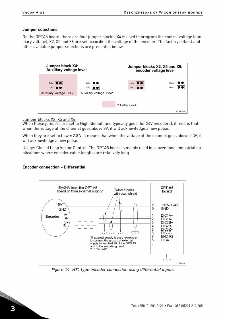
Jumper selections
On the OPTA5 board, there are four jumper blocks; X4 is used to program the control voltage (aux-iliary voltage), X2, X5 and X6 are set according the voltage of the encoder. The factory default and other available jumper selections are presented below.
Jumper blocks X2, X5 and X6:When these jumpers are set to High (default and typically good for 24V encoders), it means that when the voltage at the channel goes above 8V, it will acknowledge a new pulse.
When they are set to Low = 2.3 V, it means that when the voltage at the channel goes above 2.3V, it will acknowledge a new pulse.
Usage: Closed Loop Vector Control. The OPTA5 board is mainly used in conventional industrial ap-plications where encoder cable lengths are relatively long.
Encoder connection – Differential
Figure 14. HTL type encoder connection using differential inputs
24V
15V
24V
15V
High
Low
High
Low
Jumper block X4:Auxiliary voltage level
Auxiliary voltage +24V Auxiliary voltage +15V
= Factory default
Jumper blocks X2, X5 and X6:encoder voltage level
7254.emf
GND
A-
B-
15V**
15V/24V from the OPT-A5-board or from external supply*
OPT-A5board
.
.10 +15V/+24V9 GND
1 DIC1A+2 DIC1A-3 DIC2B+4 DIC2B-5 DIC3Z+6 DIC3Z-7 ENC1Q8 DIC1..
*If external supply is used rememberto connect the ground of externalsupply to terminal #9 of the OPT-A5and to the encoder ground**+15V/+24V
Encoder
Twisted pairswith own shield
A+
B+
DIC4
7255.emf
Tel. +358 (0) 201 2121 • Fax +358 (0)201 212 205

Descriptions of Vacon option boards vacon • 32
Encoder connection – Single-ended
Figure 15. HTL type encoder connection (open source) using single-ended inputs
NOTE! Grounding is to be connected only at the frequency converter to avoid circulating current in the shield. Isolate shield at the encoder.
It is recommended to use double shielded cable for encoder connection.
Figure 16. HTL type encoder connection (open collector) using single-ended inputs
NOTE! Grounding is to be connected only at the frequency converter to avoid circulating current in the shield. Isolate shield at the encoder.
It is recommended to use double shielded cable for encoder connection.
OPTA5 parameters
See page 27 and 28.
GND
GND
GND
15V/24V from the OPT-A5-board or from external supply*
OPT-A5board
.
.10 +15V/+24V9 GND
1 DIC1A+2 DIC1A-3 DIC2B+4 DIC2B-5 DIC3Z+6 DIC3Z-7 ENC1Q8 DIC1..
*If external supply is used rememberto connect the ground of externalsupply to terminal #9 of the OPT-A5and to the encoder ground**+15V/+24V
Encoder
Twisted pairswith own shield
+
A+
B+
DIC4
7256.emf
GND
A-
B-
15V/24V from the OPT-A5-board or from external supply*
OPT-A5board
.
.10 +15V/+24V9 GND
1 DIC1A+2 DIC1A-3 DIC2B+4 DIC2B-5 DIC3Z+6 DIC3Z-7 ENC1Q8 DIC1..
*If external supply is used rememberto connect the ground of externalsupply to terminal #9 of the OPT-A5and to the encoder ground**+15V/+24V
Encoder
Twisted pairswith own shield
+
+
+
DIC4
7257.emf
24-hour support +358 (0)201 212 575 • Email: [email protected]
3
vacon • 33 Descriptions of Vacon option boards
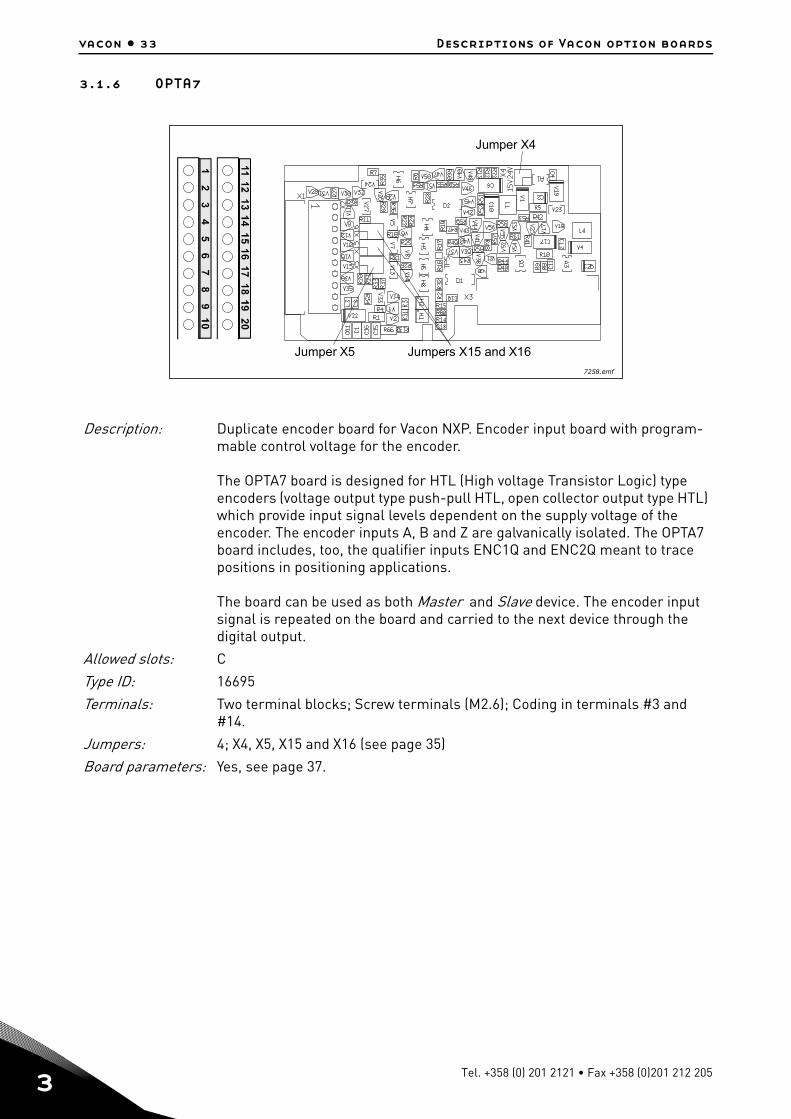
3.1.6 OPTA7
Description: Duplicate encoder board for Vacon NXP. Encoder input board with program-mable control voltage for the encoder.
The OPTA7 board is designed for HTL (High voltage Transistor Logic) type encoders (voltage output type push-pull HTL, open collector output type HTL) which provide input signal levels dependent on the supply voltage of the encoder. The encoder inputs A, B and Z are galvanically isolated. The OPTA7 board includes, too, the qualifier inputs ENC1Q and ENC2Q meant to trace positions in positioning applications.
The board can be used as both Master and Slave device. The encoder input signal is repeated on the board and carried to the next device through the digital output.
Allowed slots: C
Type ID: 16695
Terminals: Two terminal blocks; Screw terminals (M2.6); Coding in terminals #3 and #14.
Jumpers: 4; X4, X5, X15 and X16 (see page 35)
Board parameters: Yes, see page 37.
Jumper X4
Jumper X5 Jumpers X15 and X16
7258.emf
Tel. +358 (0) 201 2121 • Fax +358 (0)201 212 205
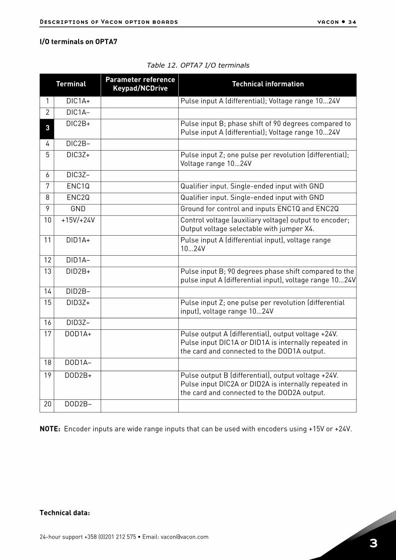
Descriptions of Vacon option boards vacon • 34
I/O terminals on OPTA7
NOTE: Encoder inputs are wide range inputs that can be used with encoders using +15V or +24V.
Technical data:
Table 12. OPTA7 I/O terminals
Terminal Parameter referenceKeypad/NCDrive Technical information
1 DIC1A+ Pulse input A (differential); Voltage range 10…24V
2 DIC1A–
3 DIC2B+ Pulse input B; phase shift of 90 degrees compared to Pulse input A (differential); Voltage range 10…24V
4 DIC2B–
5 DIC3Z+ Pulse input Z; one pulse per revolution (differential);Voltage range 10…24V
6 DIC3Z–
7 ENC1Q Qualifier input. Single-ended input with GND
8 ENC2Q Qualifier input. Single-ended input with GND
9 GND Ground for control and inputs ENC1Q and ENC2Q
10 +15V/+24V Control voltage (auxiliary voltage) output to encoder; Output voltage selectable with jumper X4.
11 DID1A+ Pulse input A (differential input), voltage range 10…24V
12 DID1A–
13 DID2B+ Pulse input B; 90 degrees phase shift compared to the pulse input A (differential input), voltage range 10…24V
14 DID2B–
15 DID3Z+ Pulse input Z; one pulse per revolution (differential input), voltage range 10…24V
16 DID3Z–
17 DOD1A+ Pulse output A (differential), output voltage +24V. Pulse input DIC1A or DID1A is internally repeated in the card and connected to the DOD1A output.
18 DOD1A–
19 DOD2B+ Pulse output B (differential), output voltage +24V. Pulse input DIC2A or DID2A is internally repeated in the card and connected to the DOD2A output.
20 DOD2B–
24-hour support +358 (0)201 212 575 • Email: [email protected]
3
vacon • 35 Descriptions of Vacon option boards
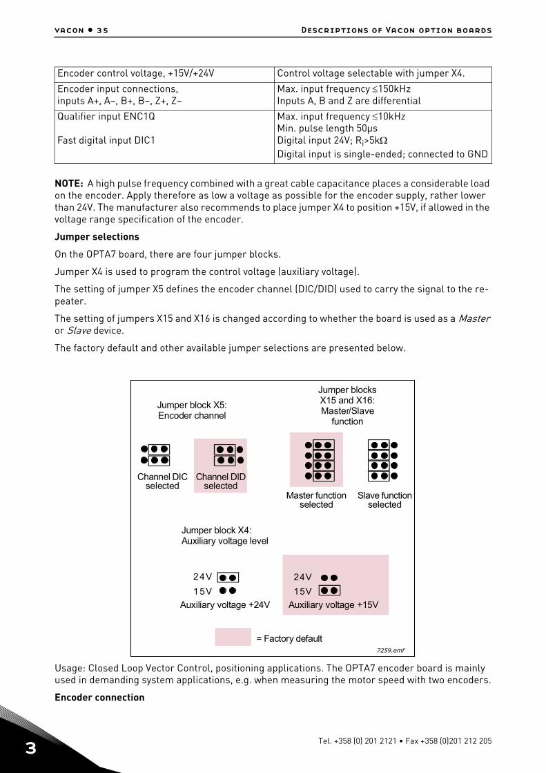
NOTE: A high pulse frequency combined with a great cable capacitance places a considerable load on the encoder. Apply therefore as low a voltage as possible for the encoder supply, rather lower than 24V. The manufacturer also recommends to place jumper X4 to position +15V, if allowed in the voltage range specification of the encoder.
Jumper selections
On the OPTA7 board, there are four jumper blocks.
Jumper X4 is used to program the control voltage (auxiliary voltage).
The setting of jumper X5 defines the encoder channel (DIC/DID) used to carry the signal to the re-peater.
The setting of jumpers X15 and X16 is changed according to whether the board is used as a Master or Slave device.
The factory default and other available jumper selections are presented below.
Usage: Closed Loop Vector Control, positioning applications. The OPTA7 encoder board is mainly used in demanding system applications, e.g. when measuring the motor speed with two encoders.
Encoder connection
Encoder control voltage, +15V/+24V Control voltage selectable with jumper X4.
Encoder input connections, inputs A+, A–, B+, B–, Z+, Z–
Max. input frequency 150kHzInputs A, B and Z are differential
Qualifier input ENC1Q
Fast digital input DIC1
Max. input frequency 10kHzMin. pulse length 50μsDigital input 24V; Ri>5kDigital input is single-ended; connected to GND
24V
15V
24V
15V
Jumper block X4:Auxiliary voltage level
Auxiliary voltage +24V Auxiliary voltage +15V
= Factory default
Jumper block X5:Encoder channel
Channel DICselected
Channel DIDselected
Master functionselected
Slave functionselected
Jumper blocksX15 and X16:Master/Slave
function
7259.emf
Tel. +358 (0) 201 2121 • Fax +358 (0)201 212 205

Descriptions of Vacon option boards vacon • 36
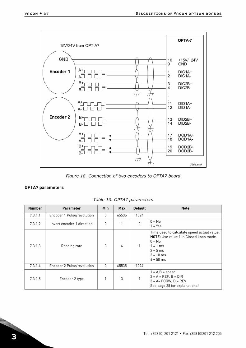
The figures below present examples of a chain connection of several OPTA7 boards (Figure 17) and a connection of two encoders to the OPTA7 option board (Figure 18).
Figure 17. Connection of encoder and three OPTA7 boards
B+
B-
A+
A-
B+
B-
A+
A-
B+
B-
A+
A-
OPT-A7(Master)
10 +15V/+24V9 GND
1 DIC1A+/DID1A+2 DIC1A-/DID1A-
3 DIC2B+/DID2B+4 DIC2B-/DID2B-
17 DOD1A+18 DOD1A-
19 DOD2B+20 DOD2B-
OPT-A7(Slave 1)
1 DIC1A+/DID1A+2 DIC1A-/DID1A-
3 DIC2B+/DID2B+4 DIC2B-/DID2B-
17 DOD1A+18 DOD1A-
19 DOD2B+20 DOD2B-
OPT-A7(Slave 2)
1 DIC1A+/DID1A+2 DIC1A-/DID1A-
3 DIC2B+/DID2B+4 DIC2B-/DID2B-
17 DOD1A+18 DOD1A-
19 DOD2B+20 DOD2B-
Encoder
7260.emf
24-hour support +358 (0)201 212 575 • Email: [email protected]
3
vacon • 37 Descriptions of Vacon option boards
Figure 18. Connection of two encoders to OPTA7 board
OPTA7 parameters
Table 13. OPTA7 parameters
Number Parameter Min Max Default Note
7.3.1.1 Encoder 1 Pulse/revolution 0 65535 1024
7.3.1.2 Invert encoder 1 direction 0 1 00 = No1 = Yes
7.3.1.3 Reading rate 0 4 1
Time used to calculate speed actual value. NOTE: Use value 1 in Closed Loop mode.0 = No1 = 1 ms2 = 5 ms3 = 10 ms4 = 50 ms
7.3.1.4 Encoder 2 Pulse/revolution 0 65535 1024
7.3.1.5 Encoder 2 type 1 3 1
1 = A,B = speed2 = A = REF, B = DIR3 = A= FORW, B = REVSee page 28 for explanations!
B+
B-
B+
B-
A+
A-
B+
B-
A+
A-
A+
A-
15V/24V from OPT-A7OPTA-7
10 +15V/+24V9 GND
1 DIC1A+2 DIC1A-
3 DIC2B+4 DIC2B-...11 DID1A+12 DID1A-
13 DID2B+14 DID2B-
17 DOD1A+18 DOD1A-
19 DOD2B+20 DOD2B-
Encoder 1
Encoder 2
GND
7261.emf
Tel. +358 (0) 201 2121 • Fax +358 (0)201 212 205

Descriptions of Vacon option boards vacon • 38
OPTA7 monitoring values
Table 14. OPTA7 monitoring values
Number Monitored value Unit Description
Mon 7.3.2.1 Encoder 1 frequency Hz Motor speed in Hz calculated from encoder 1 pulses
Mon 7.3.2.2 Encoder 1 speed rpmMotor speed in rpm calculated from encoder 1 pulses
Mon 7.3.2.3 Encoder 2 frequency Hz Motor speed in Hz calculated from encoder 2 pulses
Mon 7.3.2.4 Encoder 2 speed rpmMotor speed in rpm calculated from encoder 2 pulses
24-hour support +358 (0)201 212 575 • Email: [email protected]
3
vacon • 39 Descriptions of Vacon option boards
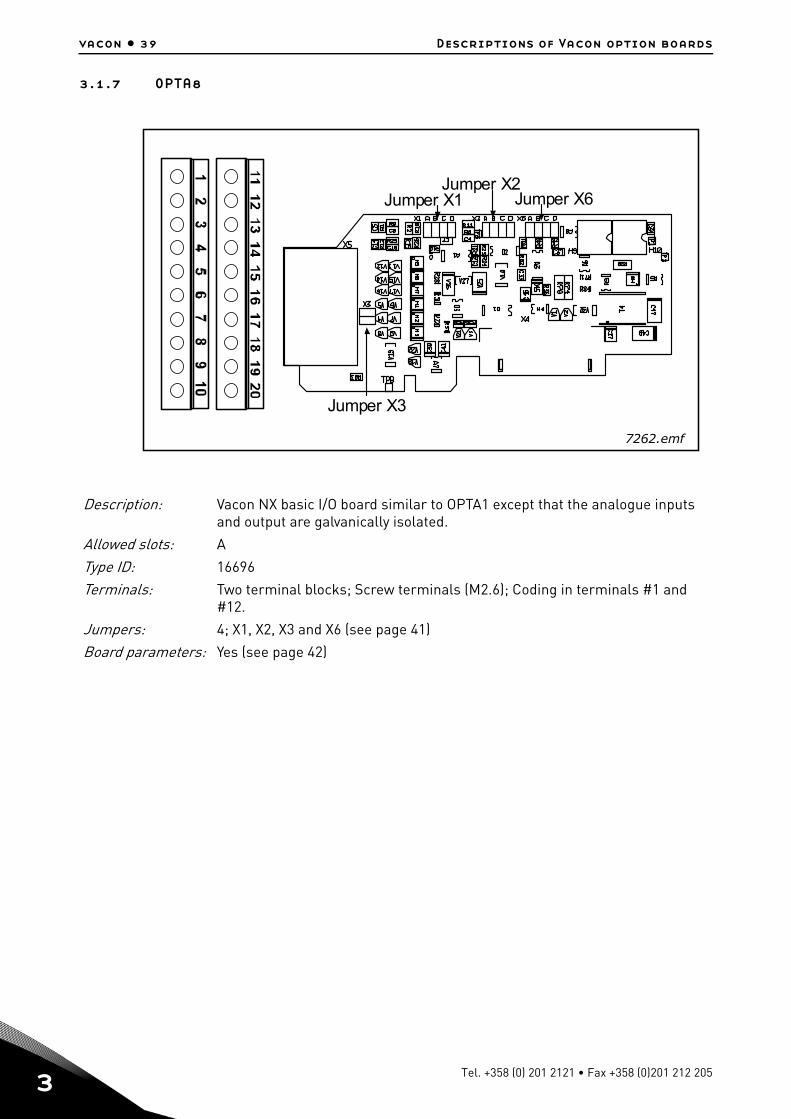
3.1.7 OPTA8
Description: Vacon NX basic I/O board similar to OPTA1 except that the analogue inputs and output are galvanically isolated.
Allowed slots: A
Type ID: 16696
Terminals: Two terminal blocks; Screw terminals (M2.6); Coding in terminals #1 and #12.
Jumpers: 4; X1, X2, X3 and X6 (see page 41)
Board parameters: Yes (see page 42)
Jumper X1Jumper X2
Jumper X6
Jumper X3
7262.emf
Tel. +358 (0) 201 2121 • Fax +358 (0)201 212 205
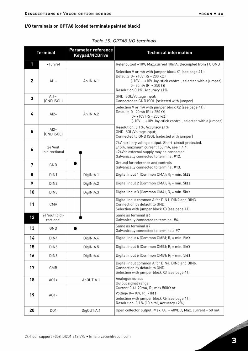
Descriptions of Vacon option boards vacon • 40
I/O terminals on OPTA8 (coded terminals painted black)
Table 15. OPTA8 I/O terminals
Terminal Parameter referenceKeypad/NCDrive Technical information
1 +10 Vref Refer.output +10V; Max.current 10mA; Decoupled from FC GND
2 AI1+ An.IN:A.1
Selection V or mA with jumper block X1 (see page 41):Default: 0– +10V (Ri = 200 k) (-10V…..+10V Joy-stick control, selected with a jumper) 0– 20mA (Ri = 250 )Resolution 0.1%; Accuracy ±1%
3 AI1– (GND ISOL)
GND ISOL/Voltage input; Connected to GND ISOL (selected with jumper)
4 AI2+ An.IN:A.2
Selection V or mA with jumper block X2 (see page 41):Default: 0– 20mA (Ri = 250 ) 0– +10V (Ri = 200 k) (-10V…..+10V Joy-stick control, selected with a jumper)
5 AI2–(GND ISOL)
Resolution: 0.1%; Accuracy ±1%GND ISOL/Voltage input;Connected to GND ISOL (selected with jumper)
6 24 Vout(bidirectional
24V auxiliary voltage output. Short-circuit protected.15%, maximum current 150 mA, see 1.4.4.+24Vdc external supply may be connected.Galvanically connected to terminal #12.
7 GNDGround for reference and controlsGalvanically connected to terminal #13.
8 DIN1 DigIN:A.1 Digital input 1 (Common CMA); Ri = min. 5k
9 DIN2 DigIN:A.2 Digital input 2 (Common CMA); Ri = min. 5k
10 DIN3 DigIN:A.3 Digital input 3 (Common CMA); Ri = min. 5k
11 CMADigital input common A for DIN1, DIN2 and DIN3.Connection by default to GND.Selection with jumper block X3 (see page 41):
12 24 Vout (bidi-rectional
Same as terminal #6Galvanically connected to terminal #6.
13 GNDSame as terminal #7Galvanically connected to terminals #7
14 DIN4 DigIN:A.4 Digital input 4 (Common CMB); Ri = min. 5k
15 DIN5 DigIN:A.5 Digital input 5 (Common CMB); Ri = min. 5k
16 DIN6 DigIN:A.6 Digital input 6 (Common CMB); Ri = min. 5k
17 CMBDigital input common A for DIN4, DIN5 and DIN6.Connection by default to GND.Selection with jumper block X3 (see page 41):
18 AO1+ AnOUT:A.1 Analogue outputOutput signal range:Current 0(4)–20mA, RL max 500 orVoltage 0—10V, RL >1kSelection with jumper block X6 (see page 41):Resolution: 0.1% (10 bits); Accuracy ±2%;
19 AO1–
20 DO1 DigOUT:A.1 Open collector output; Max. Uin = 48VDC; Max. current = 50 mA
24-hour support +358 (0)201 212 575 • Email: [email protected]
3
vacon • 41 Descriptions of Vacon option boards
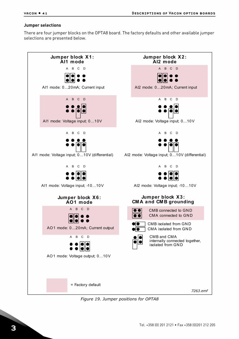
Jumper selections
There are four jumper blocks on the OPTA8 board. The factory defaults and other available jumper selections are presented below.
Figure 19. Jumper positions for OPTA8
A B C D
A B C D
A B C D
A B C D
A B C D
A B C D
A B C D
A B C D
A B C D
A B C D
Jumper block X1:AI1 mode
AI1 mode: Voltage input; 0...10V
AI1 mode: Voltage input; 0...10V (differential)
AI1 mode: Voltage input; -10...10V
Jumper block X2:AI2 mode
AI2 mode: 0...20mA; Current input
AI2 mode: Voltage input; 0...10V
AI2 mode: Voltage input; 0...10V (differential)
AI2 mode: Voltage input; -10 ...10V
Jumper block X3:CM A and CM B grounding
CMB connected to GN DCMA connected to GN D
CMB isolated from GN DCMA isolated from GN D
CMB and CMAinternally connected together,isolated from GN D
= Factory default
Jumper block X6:AO1 mode
AO1 mode: 0...20mA; Current output
AO1 mode: Voltage output; 0...10V
AI1 mode: 0...20mA; Current input
7263.emf
Tel. +358 (0) 201 2121 • Fax +358 (0)201 212 205
Descriptions of Vacon option boards vacon • 42
OPTA8 parameters
Table 16. OPTA8 board-related parameters
Number Parameter Min Max Default Note
1 AI1 mode 1 5 3
1 = 0...20mA2 = 4...20mA3 = 0...10V4 = 2...10V5 = -10...+10V
2 AI2 mode 1 5 1
1 = 0...20mA2 = 4...20mA3 = 0...10V4 = 2...10V5 = -10...+10V
3 AO1 mode 1 4 1
1 = 0...20mA2 = 4...20mA3 = 0...10V4 = 2...10V
24-hour support +358 (0)201 212 575 • Email: [email protected]
3
vacon • 43 Descriptions of Vacon option boards
3.1.8 OPTA9
I/O terminals on OPTA9
See page 20.
Jumper selections
See page 21.
OPTA9 parameters
See page 22.
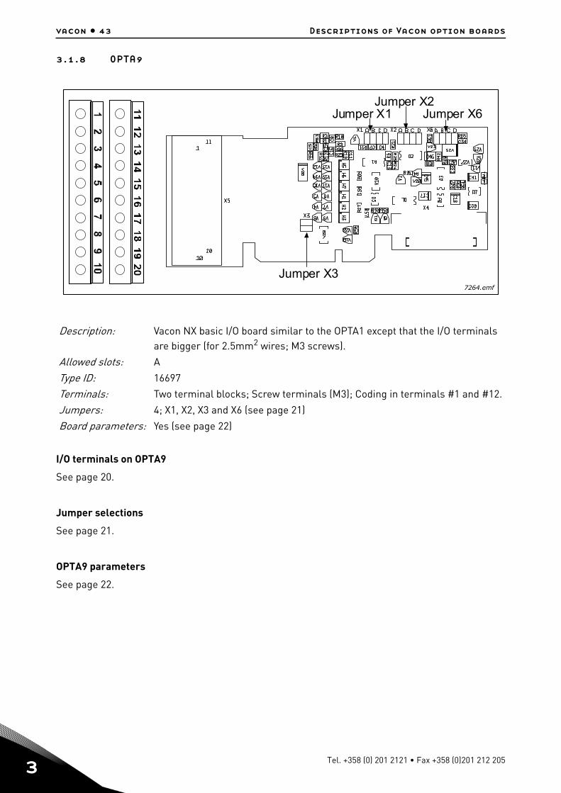
Description: Vacon NX basic I/O board similar to the OPTA1 except that the I/O terminals are bigger (for 2.5mm2 wires; M3 screws).
Allowed slots: A
Type ID: 16697
Terminals: Two terminal blocks; Screw terminals (M3); Coding in terminals #1 and #12.
Jumpers: 4; X1, X2, X3 and X6 (see page 21)
Board parameters: Yes (see page 22)
Jumper X1Jumper X2
Jumper X6
Jumper X37264.emf
Tel. +358 (0) 201 2121 • Fax +358 (0)201 212 205

Descriptions of Vacon option boards vacon • 44
3.1.9 OPTAL
I/O terminals on OPTAL
Description: Dual I/O expander board with six 42…240 VAC digital inputs, 2 analog inputs, two analog outputs, one digital output and 15 and 24 V out.
Allowed slots: A
Type ID: 16716
Terminals: Two terminal blocks; Screw terminals (M2.6, 1,5 mm2 wire terminals 1 – 10; M3, 2.5 mm2 wire terminals 11-18); No coding
Jumpers: None
Board parameters: None
Table 17. OPTAL I/O terminals
Terminal Parameter referenceKeypad/NCDrive Technical information
1 +15 V 15 V out – together with terminal 2 max 200 mA
2 +15 V 15 V out
3 AI1 An.IN:A.1 Analog input 0 – 10 V
4 AI2 An.IN:A.2 Analog input 10 V
5 GND Ground for analog signals
6 AO1+ AnOUT:A.1 Analog output 0 (4) – 20 mA
7 AO2+ AnOUT:A.2 Analog output 0 – 10 V
8 DO1 Open collector digital output , 48 V, 50 mA allowed
9 GND Ground for analog signals
10 + 24 V 24 V out – max 200 mA
11 ACIN1 DigIN:X.1 Digital input, 42…240 VAC (threshold 35V)Control voltage: "0"<33V, "1">35V
12 ACIN2 DigIN:X.2 Digital input, 42…240 VAC (threshold 35V)Control voltage: "0"<33V, "1">35V
24-hour support +358 (0)201 212 575 • Email: [email protected]
3
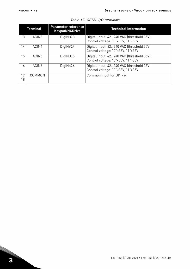
vacon • 45 Descriptions of Vacon option boards
13 ACIN3 DigIN:X.3 Digital input, 42…240 VAC (threshold 35V)Control voltage: "0"<33V, "1">35V
14 ACIN4 DigIN:X.4 Digital input, 42…240 VAC (threshold 35V)Control voltage: "0"<33V, "1">35V
15 ACIN5 DigIN:X.5 Digital input, 42…240 VAC (threshold 35V)Control voltage: "0"<33V, "1">35V
16 ACIN6 DigIN:X.6 Digital input, 42…240 VAC (threshold 35V)Control voltage: "0"<33V, "1">35V
1718
COMMON Common input for DI1 - 6
Table 17. OPTAL I/O terminals
Terminal Parameter referenceKeypad/NCDrive Technical information
Tel. +358 (0) 201 2121 • Fax +358 (0)201 212 205
Descriptions of Vacon option boards vacon • 46
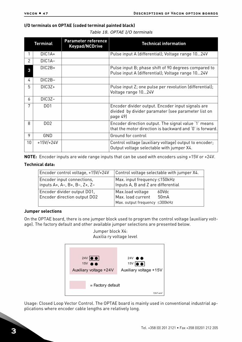
3.1.10 OPTAE
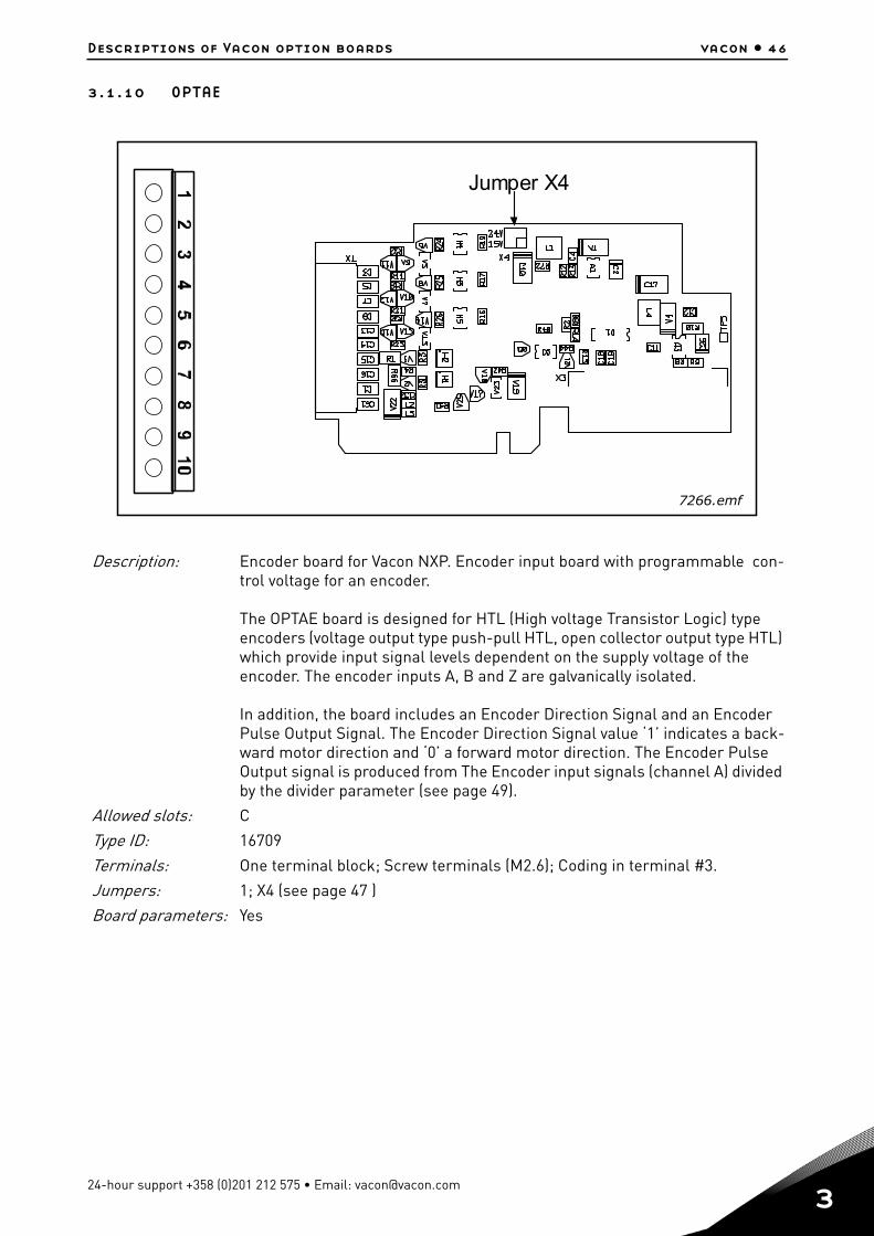
Description: Encoder board for Vacon NXP. Encoder input board with programmable con-trol voltage for an encoder.
The OPTAE board is designed for HTL (High voltage Transistor Logic) type encoders (voltage output type push-pull HTL, open collector output type HTL) which provide input signal levels dependent on the supply voltage of the encoder. The encoder inputs A, B and Z are galvanically isolated.
In addition, the board includes an Encoder Direction Signal and an Encoder Pulse Output Signal. The Encoder Direction Signal value ‘1’ indicates a back-ward motor direction and ‘0’ a forward motor direction. The Encoder Pulse Output signal is produced from The Encoder input signals (channel A) divided by the divider parameter (see page 49).
Allowed slots: C
Type ID: 16709
Terminals: One terminal block; Screw terminals (M2.6); Coding in terminal #3.
Jumpers: 1; X4 (see page 47 )
Board parameters: Yes
Jumper X4
7266.emf
24-hour support +358 (0)201 212 575 • Email: [email protected]
3
vacon • 47 Descriptions of Vacon option boards
I/O terminals on OPTAE (coded terminal painted black)
NOTE: Encoder inputs are wide range inputs that can be used with encoders using +15V or +24V.
Technical data:
Jumper selections
On the OPTAE board, there is one jumper block used to program the control voltage (auxiliary volt-age). The factory default and other available jumper selections are presented below.
Usage: Closed Loop Vector Control. The OPTAE board is mainly used in conventional industrial ap-plications where encoder cable lengths are relatively long.
Table 18. OPTAE I/O terminals
Terminal Parameter referenceKeypad/NCDrive Technical information
1 DIC1A+ Pulse input A (differential); Voltage range 10…24V
2 DIC1A–
3 DIC2B+ Pulse input B; phase shift of 90 degrees compared to Pulse input A (differential); Voltage range 10…24V
4 DIC2B–
5 DIC3Z+ Pulse input Z; one pulse per revolution (differential);Voltage range 10…24V
6 DIC3Z–
7 DO1 Encoder divider output. Encoder input signals are divided by divider paramater (see parameter list on page 49)
8 DO2 Encoder direction output. The signal value ‘1’ means that the motor direction is backward and ‘0’ is forward.
9 GND Ground for control
10 +15V/+24V Control voltage (auxiliary voltage) output to encoder; Output voltage selectable with jumper X4.
Encoder control voltage, +15V/+24V Control voltage selectable with jumper X4.
Encoder input connections, inputs A+, A–, B+, B–, Z+, Z–
Max. input frequency 150kHzInputs A, B and Z are differential
Encoder divider output DO1, Encoder direction output DO2
Max.load voltage 60Vdc Max. load current 50mAMax. output frequency 300kHz
= Factory default
24V
15V
24V
15V
Auxiliary voltage +24V Auxiliary voltage +15V
7267.emf
Jumper block X4:Auxilia ry voltage level
Tel. +358 (0) 201 2121 • Fax +358 (0)201 212 205

Descriptions of Vacon option boards vacon • 48
Encoder connection - single-ended
Figure 20. HTL type encoder connection (open source) using single-ended inputs
NOTE! Grounding is to be connected only at the frequency converter to avoid circulating current in the shield. Isolate shield at the encoder.
It is recommended to use double shielded cable for encoder connection.
Figure 21. HTL type encoder connection (open collector) using single-ended inputs
NOTE! Grounding is to be connected only at the frequency converter to avoid circulating current in the shield. Isolate shield at the encoder.
It is recommended to use double shielded cable for encoder connection.
GND
GND
GND
15V/24V from the OPT-AEboard or from external supply*
OPT-AEboard
.
.10 +15V/+24V9 GND
1 DIC1A+2 DIC1A-3 DIC2B+4 DIC2B-5 DIC3Z+6 DIC3Z-7 ENC1Q8 DIC1..
*If external supply is used rememberto connect the ground of externalsupply to terminal #9 of the OPT-AEand to the encoder ground**+15V/+24V
Encoder
Twisted pairswith own shield
+
A+
B+
7268.emf
GND
A-
B-
15V/24V from the OPT-AE-board or from external supply*
OPT-AEboard
.
.10 +15V/+24V9 GND
1 DIC1A+2 DIC1A-3 DIC2B+4 DIC2B-5 DIC3Z+6 DIC3Z-7 ENC1Q8 DIC1..
*If external supply is used rememberto connect the ground of externalsupply to terminal #9 of the OPT-AEand to the encoder ground**+15V/+24V
Encoder
Twisted pairswith own shield
+
+
+
DO2DO1
7269.emf
24-hour support +358 (0)201 212 575 • Email: [email protected]
3
vacon • 49 Descriptions of Vacon option boards
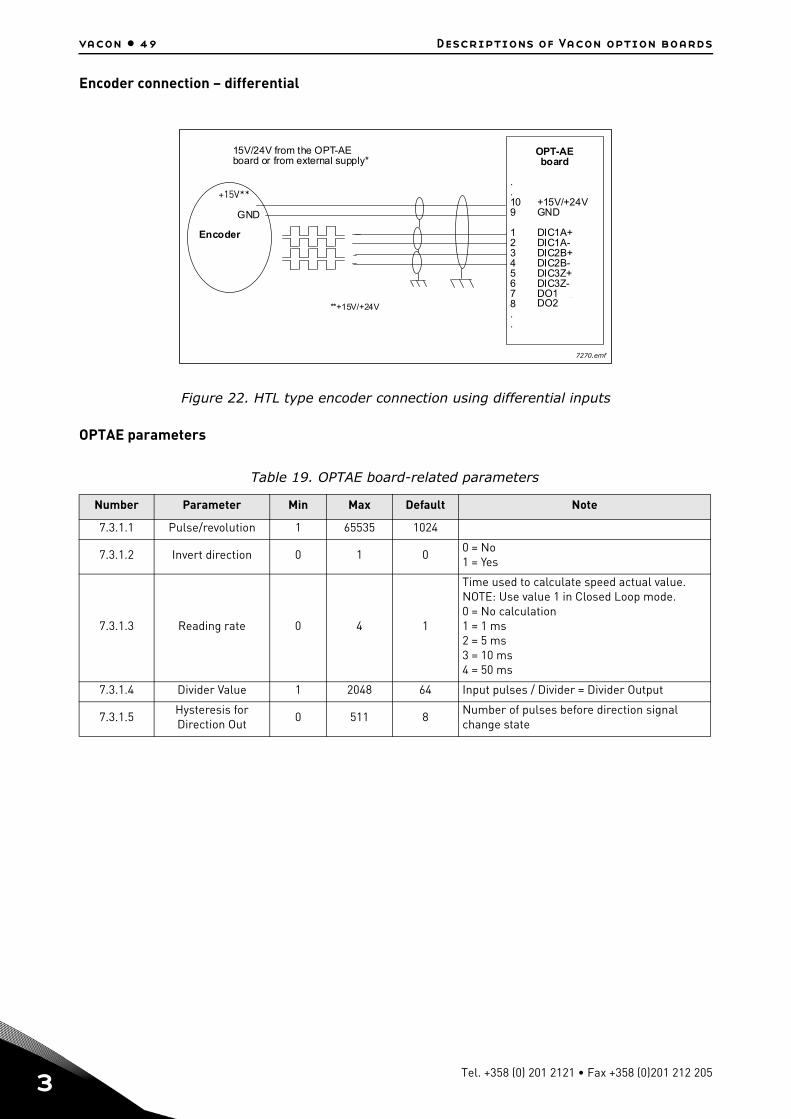
Encoder connection – differential
Figure 22. HTL type encoder connection using differential inputs
OPTAE parameters
Table 19. OPTAE board-related parameters
Number Parameter Min Max Default Note
7.3.1.1 Pulse/revolution 1 65535 1024
7.3.1.2 Invert direction 0 1 00 = No1 = Yes
7.3.1.3 Reading rate 0 4 1
Time used to calculate speed actual value. NOTE: Use value 1 in Closed Loop mode.0 = No calculation1 = 1 ms2 = 5 ms3 = 10 ms4 = 50 ms
7.3.1.4 Divider Value 1 2048 64 Input pulses / Divider = Divider Output
7.3.1.5Hysteresis for Direction Out
0 511 8Number of pulses before direction signal change state
DO2DO1
GND
15V/24V from the OPT-AEboard or from external supply*
OPT-AEboard
.
.10 +15V/+24V9 GND
1 DIC1A+2 DIC1A-3 DIC2B+4 DIC2B-5 DIC3Z+6 DIC3Z-7 ENC1Q8 DIC1..
**+15V/+24V
Encoder
+15V**
DO2DO1
7270.emf
Tel. +358 (0) 201 2121 • Fax +358 (0)201 212 205
Descriptions of Vacon option boards vacon • 50
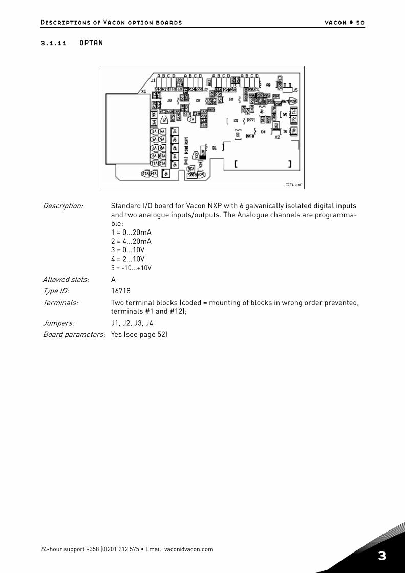
3.1.11 OPTAN
Description: Standard I/O board for Vacon NXP with 6 galvanically isolated digital inputs and two analogue inputs/outputs. The Analogue channels are programma-ble: 1 = 0...20mA 2 = 4...20mA 3 = 0...10V 4 = 2...10V 5 = -10...+10V
Allowed slots: A
Type ID: 16718
Terminals: Two terminal blocks (coded = mounting of blocks in wrong order prevented, terminals #1 and #12);
Jumpers: J1, J2, J3, J4
Board parameters: Yes (see page 52)
7271.emf
24-hour support +358 (0)201 212 575 • Email: [email protected]
3
vacon • 51 Descriptions of Vacon option boards
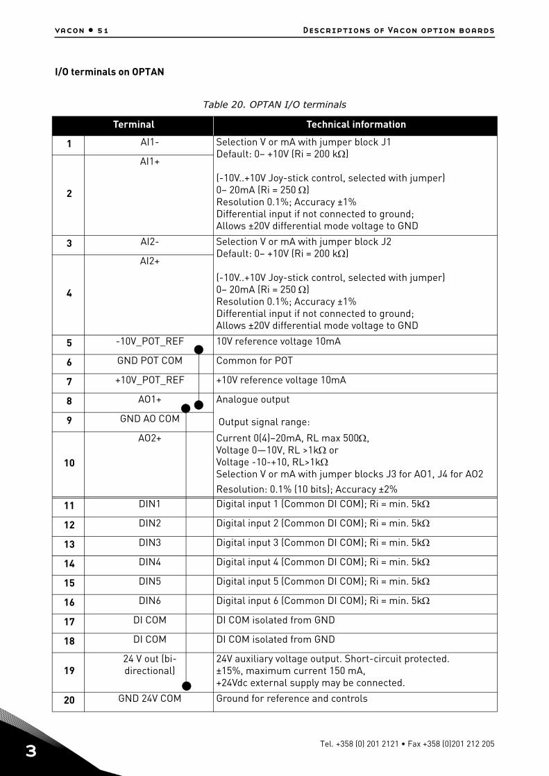
I/O terminals on OPTAN
Table 20. OPTAN I/O terminals
Terminal Technical information
1 AI1- Selection V or mA with jumper block J1 Default: 0– +10V (Ri = 200 k) (-10V..+10V Joy-stick control, selected with jumper) 0– 20mA (Ri = 250 )Resolution 0.1%; Accuracy ±1%Differential input if not connected to ground; Allows ±20V differential mode voltage to GND
2
AI1+
3 AI2- Selection V or mA with jumper block J2 Default: 0– +10V (Ri = 200 k) (-10V..+10V Joy-stick control, selected with jumper) 0– 20mA (Ri = 250 )Resolution 0.1%; Accuracy ±1%Differential input if not connected to ground; Allows ±20V differential mode voltage to GND
4
AI2+
5 -10V_POT_REF 10V reference voltage 10mA
6 GND POT COM Common for POT
7 +10V_POT_REF +10V reference voltage 10mA
8 AO1+ Analogue output
9 GND AO COM Output signal range:
10
AO2+ Current 0(4)–20mA, RL max 500,Voltage 0—10V, RL >1k orVoltage -10-+10, RL>1kSelection V or mA with jumper blocks J3 for AO1, J4 for AO2 Resolution: 0.1% (10 bits); Accuracy ±2%
11 DIN1 Digital input 1 (Common DI COM); Ri = min. 5k
12 DIN2 Digital input 2 (Common DI COM); Ri = min. 5k
13 DIN3 Digital input 3 (Common DI COM); Ri = min. 5k
14 DIN4 Digital input 4 (Common DI COM); Ri = min. 5k
15 DIN5 Digital input 5 (Common DI COM); Ri = min. 5k
16 DIN6 Digital input 6 (Common DI COM); Ri = min. 5k
17 DI COM DI COM isolated from GND
18 DI COM DI COM isolated from GND
1924 V out (bi-directional)
24V auxiliary voltage output. Short-circuit protected. ±15%, maximum current 150 mA, +24Vdc external supply may be connected.
20 GND 24V COM Ground for reference and controls
Tel. +358 (0) 201 2121 • Fax +358 (0)201 212 205
Descriptions of Vacon option boards vacon • 52
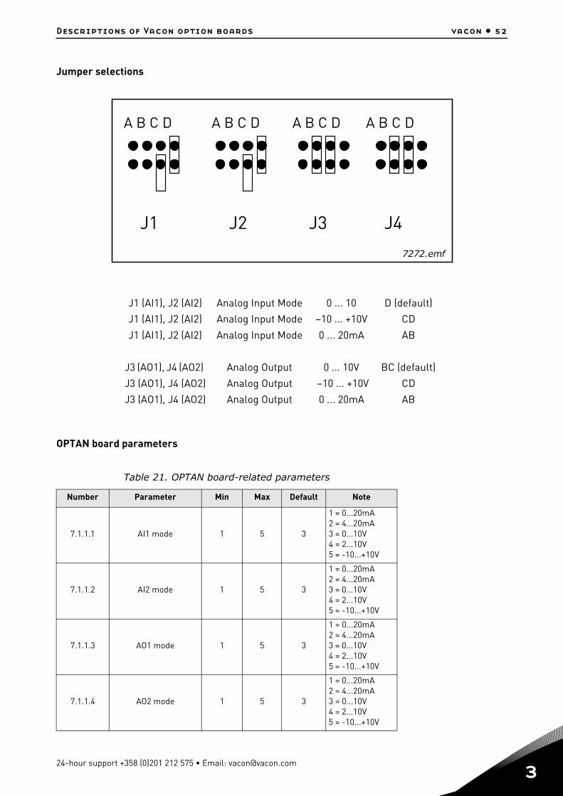
Jumper selections
OPTAN board parameters
J1 (AI1), J2 (AI2) Analog Input Mode 0 ... 10 D (default)
J1 (AI1), J2 (AI2) Analog Input Mode –10 ... +10V CD
J1 (AI1), J2 (AI2) Analog Input Mode 0 ... 20mA AB
J3 (AO1), J4 (AO2) Analog Output 0 ... 10V BC (default)
J3 (AO1), J4 (AO2) Analog Output –10 ... +10V CD
J3 (AO1), J4 (AO2) Analog Output 0 ... 20mA AB
Table 21. OPTAN board-related parameters
Number Parameter Min Max Default Note
7.1.1.1 AI1 mode 1 5 3
1 = 0...20mA 2 = 4...20mA 3 = 0...10V 4 = 2...10V 5 = -10...+10V
7.1.1.2 AI2 mode 1 5 3
1 = 0...20mA 2 = 4...20mA 3 = 0...10V 4 = 2...10V 5 = -10...+10V
7.1.1.3 AO1 mode 1 5 3
1 = 0...20mA 2 = 4...20mA 3 = 0...10V 4 = 2...10V 5 = -10...+10V
7.1.1.4 AO2 mode 1 5 3
1 = 0...20mA 2 = 4...20mA 3 = 0...10V 4 = 2...10V 5 = -10...+10V
J1 J2 J3 J4
A B C D A B C D A B C D A B C D
7272.emf
24-hour support +358 (0)201 212 575 • Email: [email protected]
3
vacon • 53 Descriptions of Vacon option boards
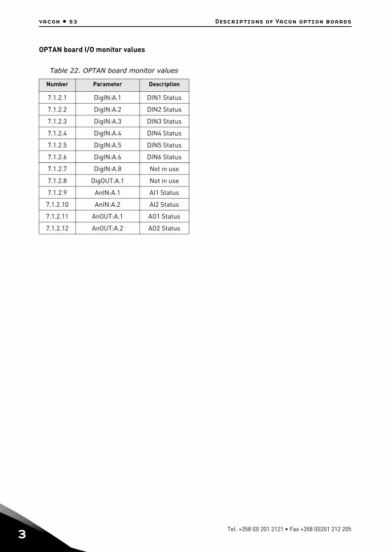
OPTAN board I/O monitor values
Table 22. OPTAN board monitor values
Number Parameter Description
7.1.2.1 DigIN:A.1 DIN1 Status
7.1.2.2 DigIN:A.2 DIN2 Status
7.1.2.3 DigIN:A.3 DIN3 Status
7.1.2.4 DigIN:A.4 DIN4 Status
7.1.2.5 DigIN:A.5 DIN5 Status
7.1.2.6 DigIN:A.6 DIN6 Status
7.1.2.7 DigIN:A.8 Not in use
7.1.2.8 DigOUT:A.1 Not in use
7.1.2.9 AnIN:A.1 AI1 Status
7.1.2.10 AnIN:A.2 AI2 Status
7.1.2.11 AnOUT:A.1 AO1 Status
7.1.2.12 AnOUT:A.2 AO2 Status
Tel. +358 (0) 201 2121 • Fax +358 (0)201 212 205
Descriptions of Vacon option boards vacon • 54
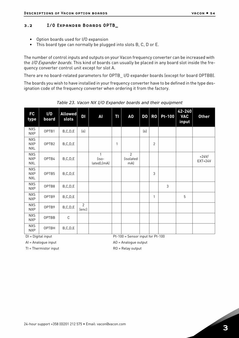
3.2 I/O Expander Boards OPTB_
• Option boards used for I/O expansion• This board type can normally be plugged into slots B, C, D or E.
The number of control inputs and outputs on your Vacon frequency converter can be increased with the I/O Expander boards. This kind of boards can usually be placed in any board slot inside the fre-quency converter control unit except for slot A.
There are no board-related parameters for OPTB_ I/O expander boards (except for board OPTBB).
The boards you wish to have installed in your frequency converter have to be defined in the type des-ignation code of the frequency converter when ordering it from the factory.
Table 23. Vacon NX I/O Expander boards and their equipment
FC type
I/O board
Allowed slots DI AI TI AO DO RO Pt-100
42-240VAC
inputOther
NXSNXP
OPTB1 B,C,D,E (6) (6)
NXSNXPNXL
OPTB2 B,C,D,E 1 2
NXSNXPNXL
OPTB4 B,C,D,E1
(iso-lated);(mA)
2(isolated
mA)
+24V/EXT+24V
NXSNXPNXL
OPTB5 B,C,D,E 3
NXSNXP
OPTB8 B,C,D,E 3
NXSNXP
OPTB9 B,C,D,E 1 5
NXSNXP
OPTB9 B,C,D,E2
(enc)
NXSNXP
OPTBB C
NXSNXP
OPTBH B,C,D,E
DI = Digital input Pt-100 = Sensor input for Pt-100
AI = Analogue input AO = Analogue output
TI = Thermistor input RO = Relay output
24-hour support +358 (0)201 212 575 • Email: [email protected]
3
vacon • 55 Descriptions of Vacon option boards
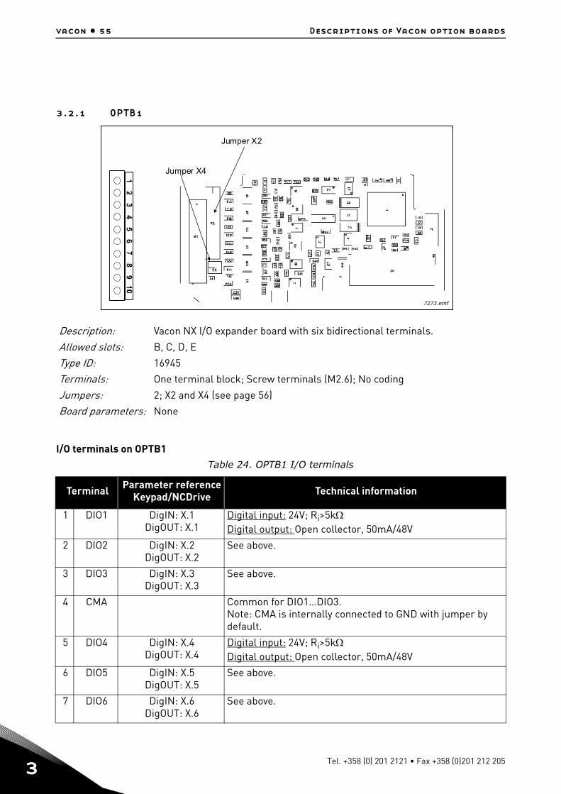
3.2.1 OPTB1
I/O terminals on OPTB1
Description: Vacon NX I/O expander board with six bidirectional terminals.
Allowed slots: B, C, D, E
Type ID: 16945
Terminals: One terminal block; Screw terminals (M2.6); No coding
Jumpers: 2; X2 and X4 (see page 56)
Board parameters: None
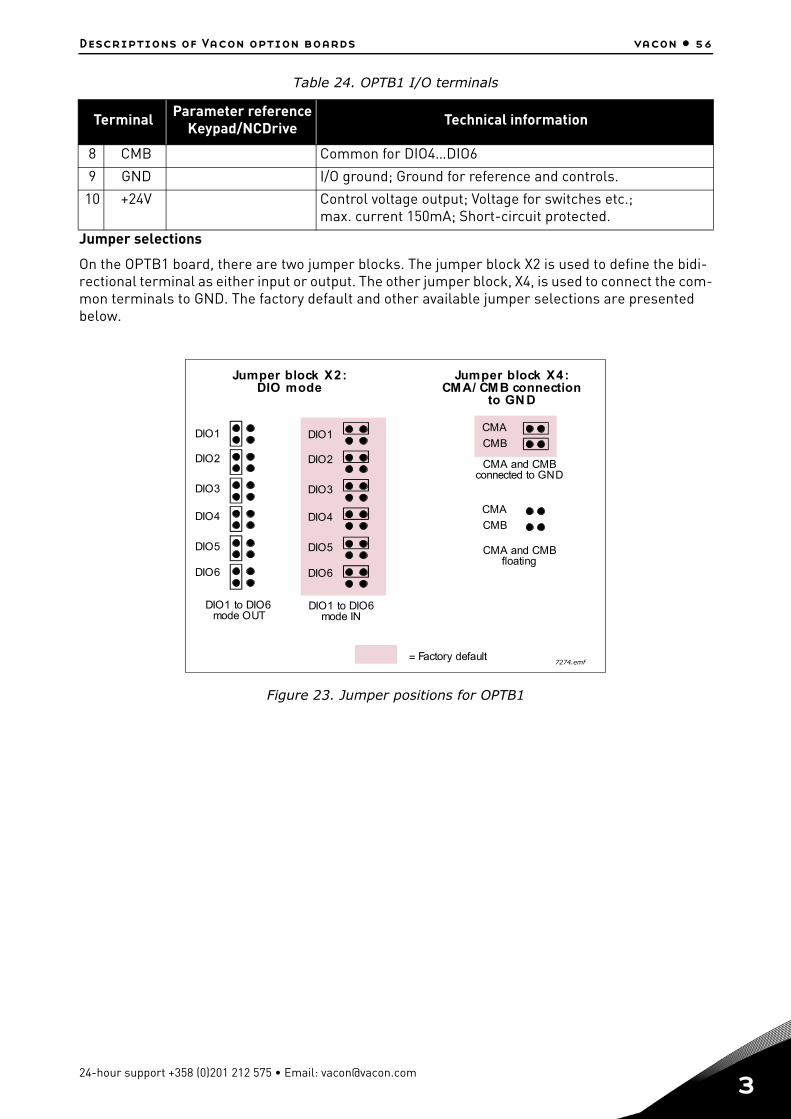
Table 24. OPTB1 I/O terminals
Terminal Parameter referenceKeypad/NCDrive Technical information
1 DIO1 DigIN: X.1DigOUT: X.1
Digital input: 24V; Ri>5kDigital output: Open collector, 50mA/48V
2 DIO2 DigIN: X.2DigOUT: X.2
See above.
3 DIO3 DigIN: X.3DigOUT: X.3
See above.
4 CMA Common for DIO1…DIO3.Note: CMA is internally connected to GND with jumper by default.
5 DIO4 DigIN: X.4DigOUT: X.4
Digital input: 24V; Ri>5kDigital output: Open collector, 50mA/48V
6 DIO5 DigIN: X.5DigOUT: X.5
See above.
7 DIO6 DigIN: X.6DigOUT: X.6
See above.
Jumper X2
Jumper X4
7273.emf
Tel. +358 (0) 201 2121 • Fax +358 (0)201 212 205
Descriptions of Vacon option boards vacon • 56
Jumper selections
On the OPTB1 board, there are two jumper blocks. The jumper block X2 is used to define the bidi-rectional terminal as either input or output. The other jumper block, X4, is used to connect the com-mon terminals to GND. The factory default and other available jumper selections are presented below.
Figure 23. Jumper positions for OPTB1
8 CMB Common for DIO4…DIO6
9 GND I/O ground; Ground for reference and controls.
10 +24V Control voltage output; Voltage for switches etc.;max. current 150mA; Short-circuit protected.
Table 24. OPTB1 I/O terminals
Terminal Parameter referenceKeypad/NCDrive Technical information
DIO1
DIO2
DIO3
DIO4
DIO5
DIO6
DIO1 to DIO6mode OUT
DIO1
DIO2
DIO3
DIO4
DIO5
DIO6
DIO1 to DIO6mode IN
= Factory default
CMA and CMBconnected to GND
CMA
CMB
CMA
CMB
CMA and CMBfloating
Jumper block X2:DIO mode
Jumper block X4:CMA/ CMB connection
to GN D
7274.emf
24-hour support +358 (0)201 212 575 • Email: [email protected]
3
vacon • 57 Descriptions of Vacon option boards
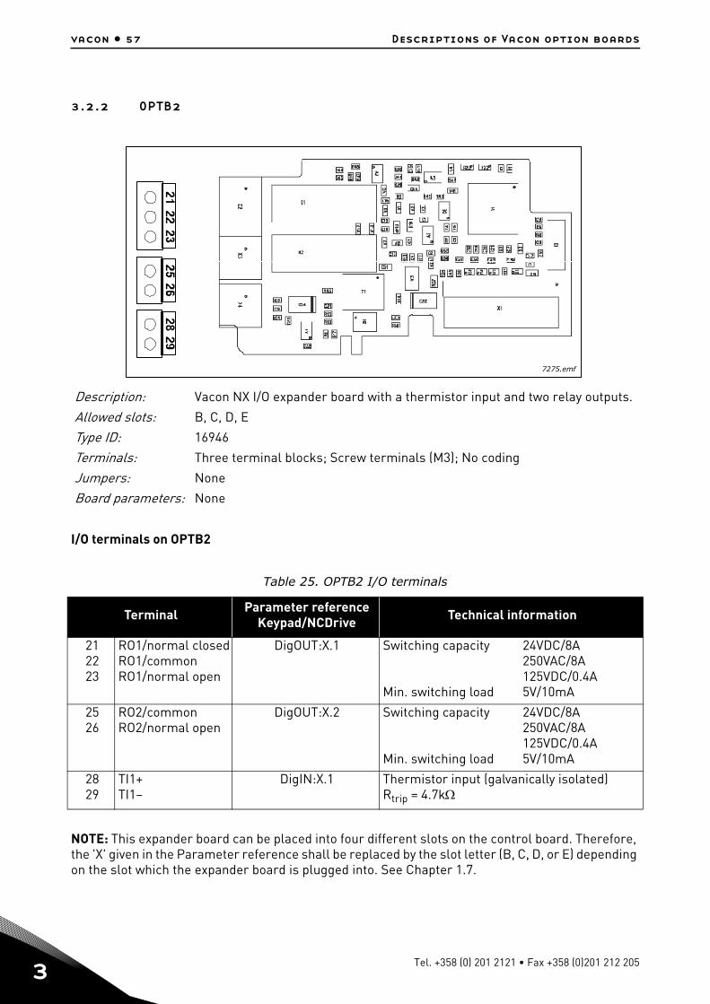
3.2.2 OPTB2
I/O terminals on OPTB2
NOTE: This expander board can be placed into four different slots on the control board. Therefore, the 'X' given in the Parameter reference shall be replaced by the slot letter (B, C, D, or E) depending on the slot which the expander board is plugged into. See Chapter 1.7.
Description: Vacon NX I/O expander board with a thermistor input and two relay outputs.
Allowed slots: B, C, D, E
Type ID: 16946
Terminals: Three terminal blocks; Screw terminals (M3); No coding
Jumpers: None
Board parameters: None
Table 25. OPTB2 I/O terminals
Terminal Parameter referenceKeypad/NCDrive Technical information
212223
RO1/normal closedRO1/commonRO1/normal open
DigOUT:X.1 Switching capacity
Min. switching load
24VDC/8A250VAC/8A125VDC/0.4A5V/10mA
2526
RO2/commonRO2/normal open
DigOUT:X.2 Switching capacity
Min. switching load
24VDC/8A250VAC/8A125VDC/0.4A5V/10mA
2829
TI1+TI1–
DigIN:X.1 Thermistor input (galvanically isolated)Rtrip = 4.7k
7275.emf
Tel. +358 (0) 201 2121 • Fax +358 (0)201 212 205

Descriptions of Vacon option boards vacon • 58
3.2.3 OPTB4
I/O terminals on OPTB4
NOTE: This expander board can be placed into four different slots on the control board. Therefore, the 'X' given in the Parameter reference shall be replaced by the slot letter (B, C, D, or E) depending on the slot which the expander board is plugged into. See Chapter1.7.
Description: Vacon NX I/O expander board with one galvanically isolated analogue input and two galvanically isolated analogue outputs (standard signals 0(4)…20mA).
Allowed slots: B, C, D, E
Type ID: 16948
Terminals: One terminal block; Screw terminals (M2.6); No coding
Jumpers: None
Board parameters: None
Table 26. OPTB4 I/O terminals
Terminal Parameter referenceKeypad/NCDrive Technical information
1 AI1+ AnIN:X.1 0(4)…20mA; Ri=250; galvanically isolatedResolution 10 bits/0.1%; Accuracy ±1% of the full dis-play
2 AI1–
3 AO1+ AnOUT:X.1 0(4)…20mA; RL<500; Resolution 10 bits/0.1%; Accuracy ±2% (galvanically isolated)4 AO1–
5 AO2+ AnOUT:X.2 0(4)…20mA; RL<500; Resolution 10 bits/0.1%; Accuracy ±2% (galvanically isolated)6 AO2–
7 GND 24V (±15%); Max. load 250mA (total load from EXT+24V outputs), max. 150mA from one board. See Figure 3 on page 7.
8 GND
9 GND 24V (±15%), in special applications where PLC type functions are included in the control module, this input can be used as external auxiliary power supply for control boards as well as for I/O boards.
10 +24V
7276.emf
24-hour support +358 (0)201 212 575 • Email: [email protected]
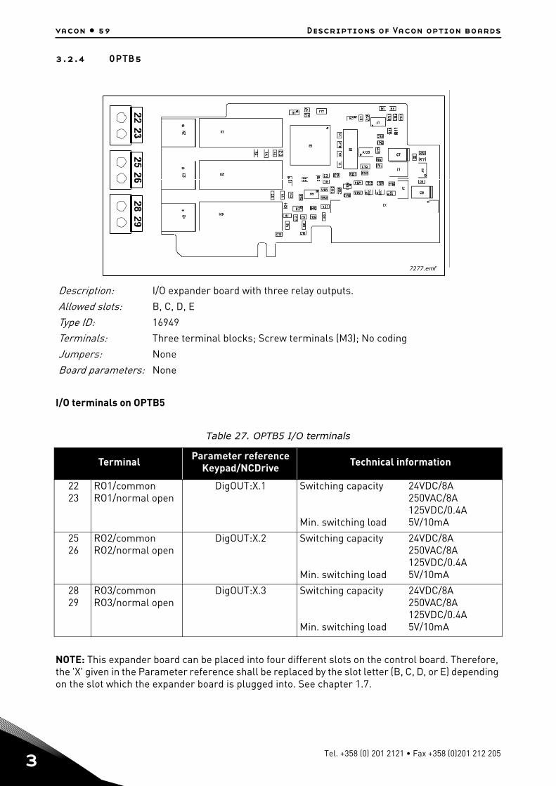
3
vacon • 59 Descriptions of Vacon option boards
3.2.4 OPTB5
I/O terminals on OPTB5
NOTE: This expander board can be placed into four different slots on the control board. Therefore, the 'X' given in the Parameter reference shall be replaced by the slot letter (B, C, D, or E) depending on the slot which the expander board is plugged into. See chapter 1.7.
Description: I/O expander board with three relay outputs.
Allowed slots: B, C, D, E
Type ID: 16949
Terminals: Three terminal blocks; Screw terminals (M3); No coding
Jumpers: None
Board parameters: None
Table 27. OPTB5 I/O terminals
Terminal Parameter referenceKeypad/NCDrive Technical information
2223
RO1/commonRO1/normal open
DigOUT:X.1 Switching capacity
Min. switching load
24VDC/8A250VAC/8A125VDC/0.4A5V/10mA
2526
RO2/commonRO2/normal open
DigOUT:X.2 Switching capacity
Min. switching load
24VDC/8A250VAC/8A125VDC/0.4A5V/10mA
2829
RO3/commonRO3/normal open
DigOUT:X.3 Switching capacity
Min. switching load
24VDC/8A250VAC/8A125VDC/0.4A5V/10mA
7277.emf
Tel. +358 (0) 201 2121 • Fax +358 (0)201 212 205
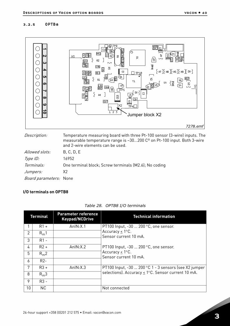
Descriptions of Vacon option boards vacon • 60
3.2.5 OPTB8
I/O terminals on OPTB8
Description: Temperature measuring board with three Pt-100 sensor (3-wire) inputs. The measurable temperature range is –30...200 Cº on Pt-100 input. Both 3-wire and 2-wire elements can be used.
Allowed slots: B, C, D, E
Type ID: 16952
Terminals: One terminal block; Screw terminals (M2.6); No coding
Jumpers: X2
Board parameters: None
Table 28. OPTB8 I/O terminals
Terminal Parameter referenceKeypad/NCDrive Technical information
1 R1 + AnIN:X.1 PT100 Input, -30 … 200 C, one sensor.Accuracy < 1C.Sensor current 10 mA.
2 Rm1
3 R1 -
4 R2 + AnIN:X.2 PT100 Input, -30 … 200 C, one sensor.Accuracy < 1C.Sensor current 10 mA.
5 Rm2
6 R2-
7 R3 + AnIN:X.3 PT100 Input, -30 … 200 C 1 - 3 sensors (see X2 jumper selections). Accuracy < 1C. Sensor current 10 mA.8 Rm3
9 R3 -
10 NC Not connected
Jumper block X2
7278.emf
24-hour support +358 (0)201 212 575 • Email: [email protected]

3
vacon • 61 Descriptions of Vacon option boards
Connection of PT100 sensors
One PT100-sensor can be connected to the first two inputs (terminals 1 to 3 and 4 to 6) and up to three sensors to the third input (terminals 7 to 9). The sensors must be connected in series with a two- or three-wire connection. See Chapter Jumper selections below.
NOTE: • This expander board can be placed into four different slots on the control board. Therefore,
the 'X' given in the Parameter reference shall be replaced by the slot letter (B, C, D, or E) depending on the slot which the expander board is plugged into. See chapter 1.7.
• Insulation level 4kV/sqrt(2) (DIN VDE 01 10-1). 2kV in sensor and 2kV in option board.
Jumper selections
Up to three PT100 sensors can be connected to the third PT100 input. You can select the number of sensors in use with jumper block X2:
R+
Rm
R-
R+
R-
R+
Rm
R-
R+
R-
3-wire connection 2-wire connection
Connection of one sensor
3-wire connection 2-wire connection
Connection of several sensors
7279.emf
1 2 31 2 31 2 31 Sensor 2 Sensors 3 Sensors
= Factory default
7280.emf
Tel. +358 (0) 201 2121 • Fax +358 (0)201 212 205
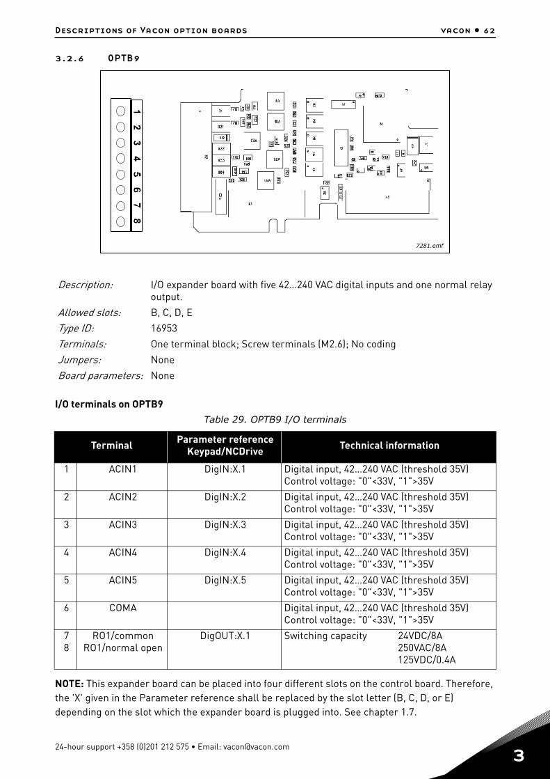
Descriptions of Vacon option boards vacon • 62
3.2.6 OPTB9
I/O terminals on OPTB9
NOTE: This expander board can be placed into four different slots on the control board. Therefore, the 'X' given in the Parameter reference shall be replaced by the slot letter (B, C, D, or E) depending on the slot which the expander board is plugged into. See chapter 1.7.
Description: I/O expander board with five 42…240 VAC digital inputs and one normal relay output.
Allowed slots: B, C, D, E
Type ID: 16953
Terminals: One terminal block; Screw terminals (M2.6); No coding
Jumpers: None
Board parameters: None
Table 29. OPTB9 I/O terminals
Terminal Parameter referenceKeypad/NCDrive Technical information
1 ACIN1 DigIN:X.1 Digital input, 42…240 VAC (threshold 35V)Control voltage: "0"<33V, "1">35V
2 ACIN2 DigIN:X.2 Digital input, 42…240 VAC (threshold 35V)Control voltage: "0"<33V, "1">35V
3 ACIN3 DigIN:X.3 Digital input, 42…240 VAC (threshold 35V)Control voltage: "0"<33V, "1">35V
4 ACIN4 DigIN:X.4 Digital input, 42…240 VAC (threshold 35V)Control voltage: "0"<33V, "1">35V
5 ACIN5 DigIN:X.5 Digital input, 42…240 VAC (threshold 35V)Control voltage: "0"<33V, "1">35V
6 COMA Digital input, 42…240 VAC (threshold 35V)Control voltage: "0"<33V, "1">35V
78
RO1/commonRO1/normal open
DigOUT:X.1 Switching capacity 24VDC/8A250VAC/8A125VDC/0.4A
7281.emf
24-hour support +358 (0)201 212 575 • Email: [email protected]
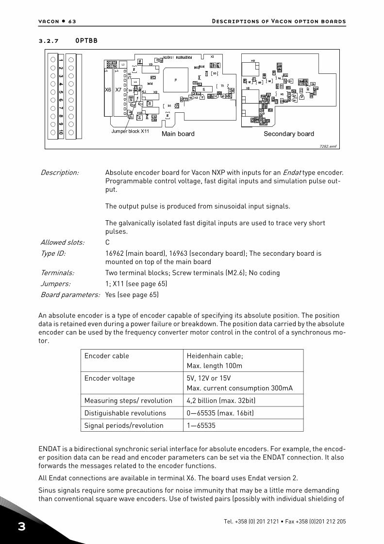
3
vacon • 63 Descriptions of Vacon option boards
3.2.7 OPTBB
An absolute encoder is a type of encoder capable of specifying its absolute position. The position data is retained even during a power failure or breakdown. The position data carried by the absolute encoder can be used by the frequency converter motor control in the control of a synchronous mo-tor.
ENDAT is a bidirectional synchronic serial interface for absolute encoders. For example, the encod-er position data can be read and encoder parameters can be set via the ENDAT connection. It also forwards the messages related to the encoder functions.
All Endat connections are available in terminal X6. The board uses Endat version 2.
Sinus signals require some precautions for noise immunity that may be a little more demanding than conventional square wave encoders. Use of twisted pairs (possibly with individual shielding of
Description: Absolute encoder board for Vacon NXP with inputs for an Endat type encoder. Programmable control voltage, fast digital inputs and simulation pulse out-put.
The output pulse is produced from sinusoidal input signals.
The galvanically isolated fast digital inputs are used to trace very short pulses.
Allowed slots: C
Type ID: 16962 (main board), 16963 (secondary board); The secondary board is mounted on top of the main board
Terminals: Two terminal blocks; Screw terminals (M2.6); No coding
Jumpers: 1; X11 (see page 65)
Board parameters: Yes (see page 65)
Encoder cable Heidenhain cable; Max. length 100m
Encoder voltage 5V, 12V or 15VMax. current consumption 300mA
Measuring steps/ revolution 4,2 billion (max. 32bit)
Distiguishable revolutions 0—65535 (max. 16bit)
Signal periods/revolution 1—65535
X6 X7
Main boardJumper block X11 Secondary board
7282.emf
Tel. +358 (0) 201 2121 • Fax +358 (0)201 212 205
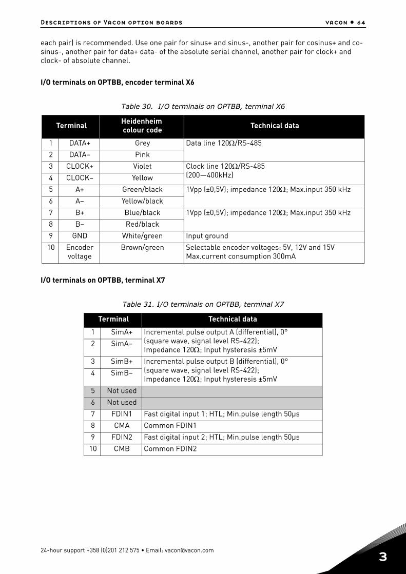
Descriptions of Vacon option boards vacon • 64
each pair) is recommended. Use one pair for sinus+ and sinus-, another pair for cosinus+ and co-sinus-, another pair for data+ data- of the absolute serial channel, another pair for clock+ and clock- of absolute channel.
I/O terminals on OPTBB, encoder terminal X6
I/O terminals on OPTBB, terminal X7
Table 30. I/O terminals on OPTBB, terminal X6
Terminal Heidenheim colour code Technical data
1 DATA+ Grey Data line 120/RS-485
2 DATA– Pink
3 CLOCK+ Violet Clock line 120/RS-485(200—400kHz)4 CLOCK– Yellow
5 A+ Green/black 1Vpp (±0,5V); impedance 120; Max.input 350 kHz
6 A– Yellow/black
7 B+ Blue/black 1Vpp (±0,5V); impedance 120; Max.input 350 kHz
8 B– Red/black
9 GND White/green Input ground
10 Encoder voltage
Brown/green Selectable encoder voltages: 5V, 12V and 15VMax.current consumption 300mA
Table 31. I/O terminals on OPTBB, terminal X7
Terminal Technical data
1 SimA+ Incremental pulse output A (differential), 0°(square wave, signal level RS-422); Impedance 120; Input hysteresis ±5mV
2 SimA–
3 SimB+ Incremental pulse output B (differential), 0°(square wave, signal level RS-422); Impedance 120; Input hysteresis ±5mV
4 SimB–
5 Not used
6 Not used
7 FDIN1 Fast digital input 1; HTL; Min.pulse length 50μs
8 CMA Common FDIN1
9 FDIN2 Fast digital input 2; HTL; Min.pulse length 50μs
10 CMB Common FDIN2
24-hour support +358 (0)201 212 575 • Email: [email protected]
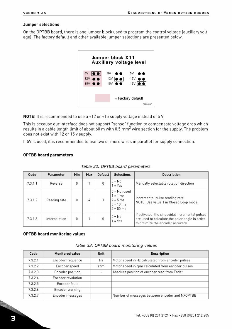
3
vacon • 65 Descriptions of Vacon option boards
Jumper selections
On the OPTBB board, there is one jumper block used to program the control voltage (auxiliary volt-age). The factory default and other available jumper selections are presented below.
NOTE! It is recommended to use a +12 or +15 supply voltage instead of 5 V.
This is because our interface does not support "sense" function to compensate voltage drop which results in a cable length limit of about 60 m with 0.5 mm2 wire section for the supply. The problem does not exist with 12 or 15 v supply.
If 5V is used, it is recommended to use two or more wires in parallel for supply connection.
OPTBB board parameters
OPTBB board monitoring values
Table 32. OPTBB board parameters
Code Parameter Min Max Default Selections Description
7.3.1.1 Reverse 0 1 00 = No1 = Yes
Manually selectable rotation direction
7.3.1.2 Reading rate 0 4 1
0 = Not used1 = 1 ms2 = 5 ms3 = 10 ms4 = 50 ms
Incremental pulse reading rate.NOTE: Use value 1 in Closed Loop mode.
7.3.1.3 Interpolation 0 1 00 = No1 = Yes
If activated, the sinusoidal incremental pulses are used to calculate the polar angle in order to optimize the encoder accuracy
Table 33. OPTBB board monitoring values
Code Monitored value Unit Description
7.3.2.1 Encoder frequence Hz Motor speed in Hz calculated from encoder pulses
7.3.2.2 Encoder speed rpm Motor speed in rpm calculated from encoder pulses
7.3.2.3 Encoder position - Absolute position of encoder read from Endat
7.3.2.4 Encoder revolution
7.3.2.5 Encoder fault
7.3.2.6 Encoder warning
7.3.2.7 Encoder messages Number of messages between encoder and NXOPTBB
5V
12V
15V
5V
12V
15V
5V
12V
15V
Jumper block X11Aux iliary voltage level
= Factory default7283.emf
Tel. +358 (0) 201 2121 • Fax +358 (0)201 212 205
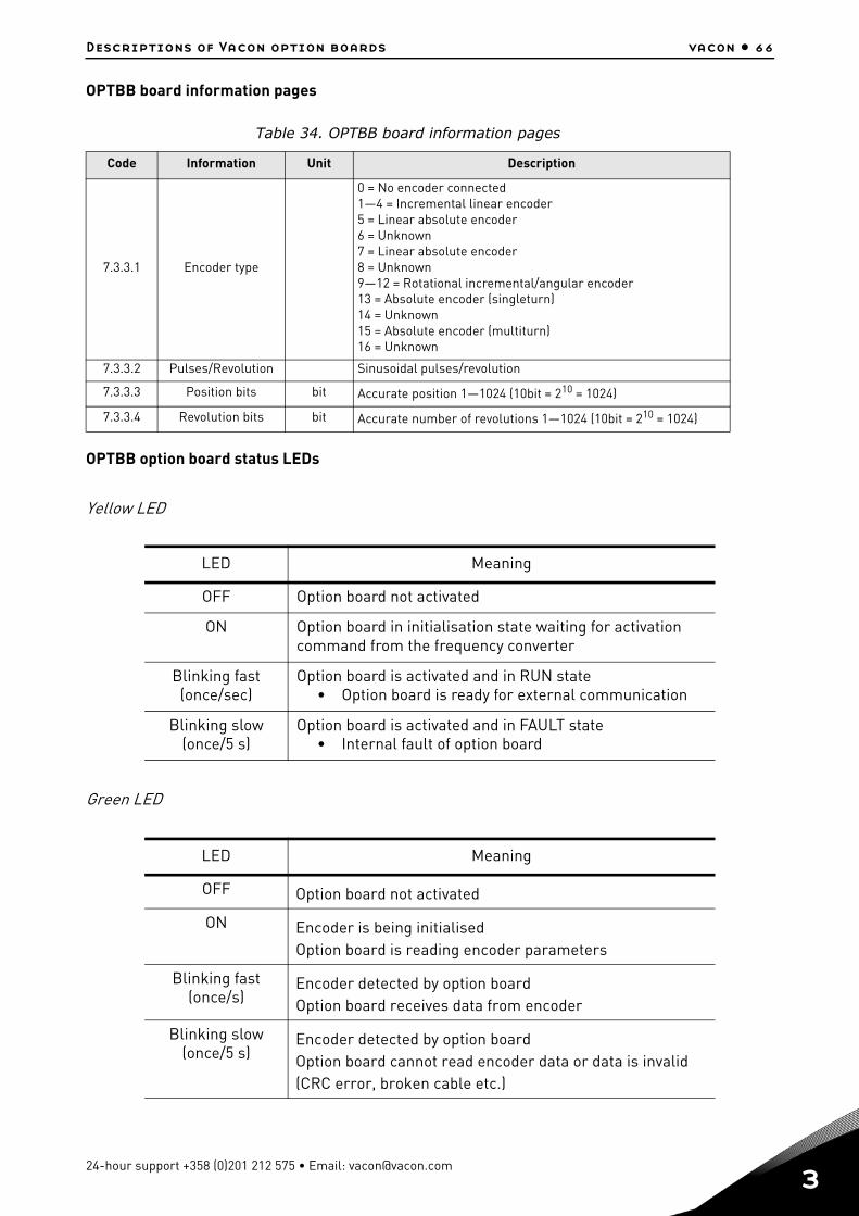
Descriptions of Vacon option boards vacon • 66
OPTBB board information pages
OPTBB option board status LEDs
Yellow LED
Green LED
Table 34. OPTBB board information pages
Code Information Unit Description
7.3.3.1 Encoder type
0 = No encoder connected1—4 = Incremental linear encoder5 = Linear absolute encoder6 = Unknown7 = Linear absolute encoder8 = Unknown9—12 = Rotational incremental/angular encoder13 = Absolute encoder (singleturn)14 = Unknown15 = Absolute encoder (multiturn)16 = Unknown
7.3.3.2 Pulses/Revolution Sinusoidal pulses/revolution
7.3.3.3 Position bits bit Accurate position 1—1024 (10bit = 210 = 1024)
7.3.3.4 Revolution bits bit Accurate number of revolutions 1—1024 (10bit = 210 = 1024)
LED Meaning
OFF Option board not activated
ON Option board in initialisation state waiting for activation command from the frequency converter
Blinking fast(once/sec)
Option board is activated and in RUN state• Option board is ready for external communication
Blinking slow(once/5 s)
Option board is activated and in FAULT state• Internal fault of option board
LED Meaning
OFF Option board not activated
ON Encoder is being initialisedOption board is reading encoder parameters
Blinking fast(once/s)
Encoder detected by option boardOption board receives data from encoder
Blinking slow(once/5 s)
Encoder detected by option boardOption board cannot read encoder data or data is invalid (CRC error, broken cable etc.)
24-hour support +358 (0)201 212 575 • Email: [email protected]
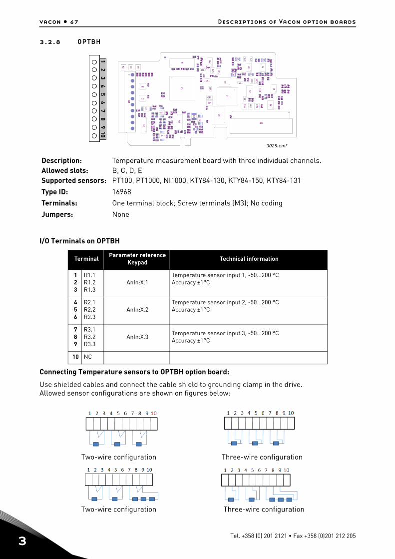
3
vacon • 67 Descriptions of Vacon option boards
3.2.8 OPTBH
I/O Terminals on OPTBH
Connecting Temperature sensors to OPTBH option board:
Use shielded cables and connect the cable shield to grounding clamp in the drive. Allowed sensor configurations are shown on figures below:
Two-wire configuration Three-wire configuration
Two-wire configuration Three-wire configuration
Description: Temperature measurement board with three individual channels.Allowed slots: B, C, D, ESupported sensors: PT100, PT1000, NI1000, KTY84-130, KTY84-150, KTY84-131
Type ID: 16968
Terminals: One terminal block; Screw terminals (M3); No coding
Jumpers: None
Terminal Parameter referenceKeypad
Technical information
123
R1.1R1.2R1.3
AnIn:X.1Temperature sensor input 1, -50...200 °CAccuracy ±1°C
456
R2.1R2.2R2.3
AnIn:X.2Temperature sensor input 2, -50...200 °CAccuracy ±1°C
789
R3.1R3.2R3.3
AnIn:X.3Temperature sensor input 3, -50...200 °CAccuracy ±1°C
10 NC
3025.emf
12
34
56
78
910
Tel. +358 (0) 201 2121 • Fax +358 (0)201 212 205

Descriptions of Vacon option boards vacon • 68
OPTBH board parameters
Code Parameter Min Max Unit Default ID Description
7.x.1.1 Sensor 1 type 0 6 0
0 = No Sensor1 = PT1002 = PT10003 = Ni10004 = KTY845 = 2 x PT1006 = 3 x PT100
7.x.1.2 Sensor 2 type 0 6 0 See above
7.x.1.3 Sensor 3 type 0 6 0 See above
24-hour support +358 (0)201 212 575 • Email: [email protected]
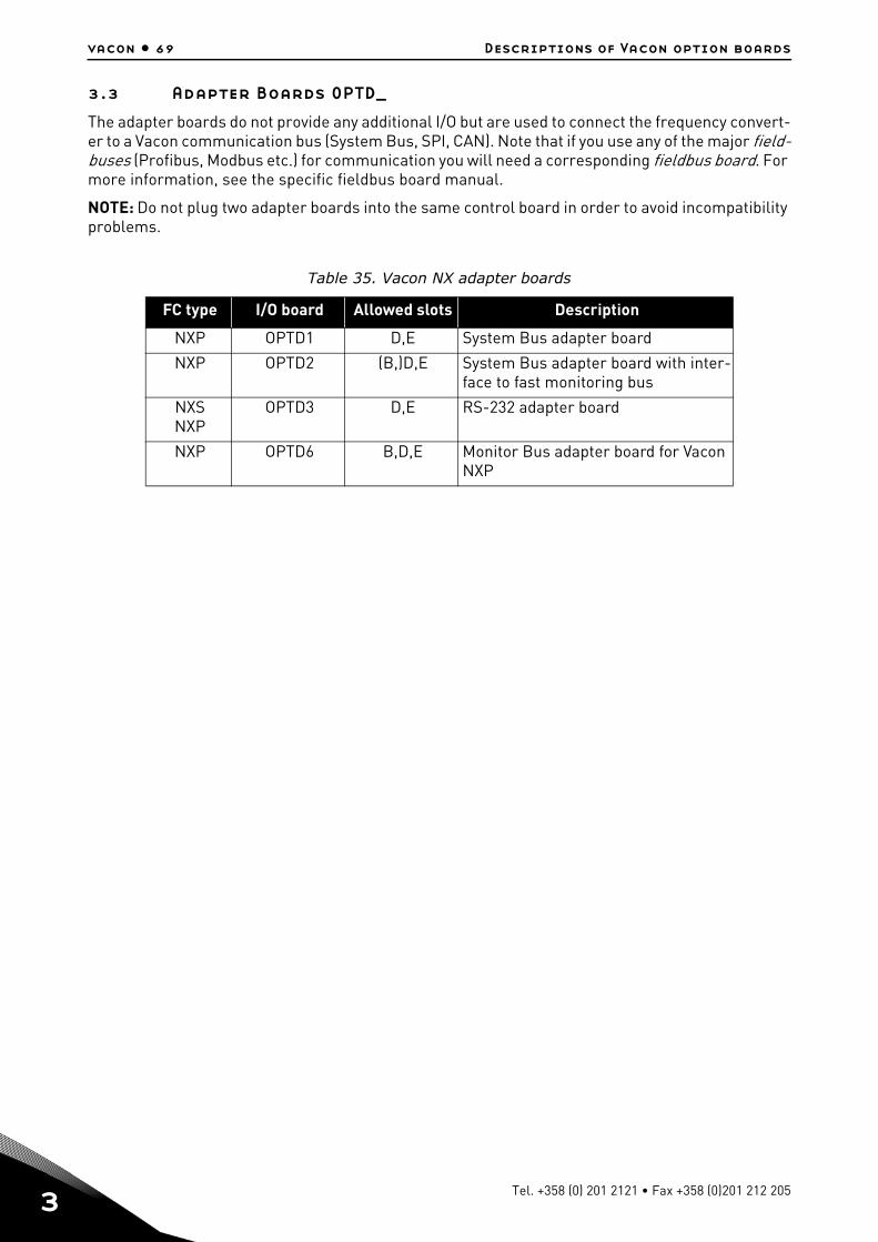
3
vacon • 69 Descriptions of Vacon option boards
3.3 Adapter Boards OPTD_
The adapter boards do not provide any additional I/O but are used to connect the frequency convert-er to a Vacon communication bus (System Bus, SPI, CAN). Note that if you use any of the major field-buses (Profibus, Modbus etc.) for communication you will need a corresponding fieldbus board. For more information, see the specific fieldbus board manual.
NOTE: Do not plug two adapter boards into the same control board in order to avoid incompatibility problems.
Table 35. Vacon NX adapter boards
FC type I/O board Allowed slots Description
NXP OPTD1 D,E System Bus adapter board
NXP OPTD2 (B,)D,E System Bus adapter board with inter-face to fast monitoring bus
NXSNXP
OPTD3 D,E RS-232 adapter board
NXP OPTD6 B,D,E Monitor Bus adapter board for Vacon NXP
Tel. +358 (0) 201 2121 • Fax +358 (0)201 212 205
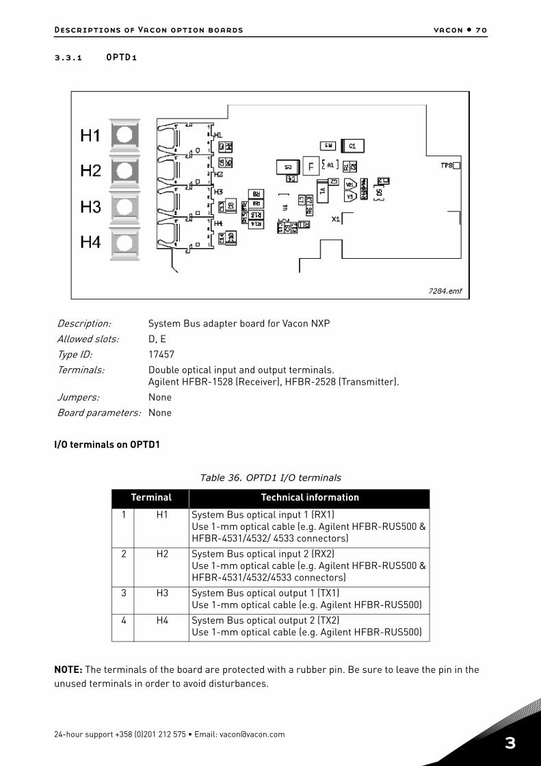
Descriptions of Vacon option boards vacon • 70
3.3.1 OPTD1
I/O terminals on OPTD1
NOTE: The terminals of the board are protected with a rubber pin. Be sure to leave the pin in the unused terminals in order to avoid disturbances.
Description: System Bus adapter board for Vacon NXP
Allowed slots: D, E
Type ID: 17457
Terminals: Double optical input and output terminals.Agilent HFBR-1528 (Receiver), HFBR-2528 (Transmitter).
Jumpers: None
Board parameters: None
Table 36. OPTD1 I/O terminals
Terminal Technical information
1 H1 System Bus optical input 1 (RX1)Use 1-mm optical cable (e.g. Agilent HFBR-RUS500 & HFBR-4531/4532/ 4533 connectors)
2 H2 System Bus optical input 2 (RX2)Use 1-mm optical cable (e.g. Agilent HFBR-RUS500 & HFBR-4531/4532/4533 connectors)
3 H3 System Bus optical output 1 (TX1)Use 1-mm optical cable (e.g. Agilent HFBR-RUS500)
4 H4 System Bus optical output 2 (TX2)Use 1-mm optical cable (e.g. Agilent HFBR-RUS500)
24-hour support +358 (0)201 212 575 • Email: [email protected]
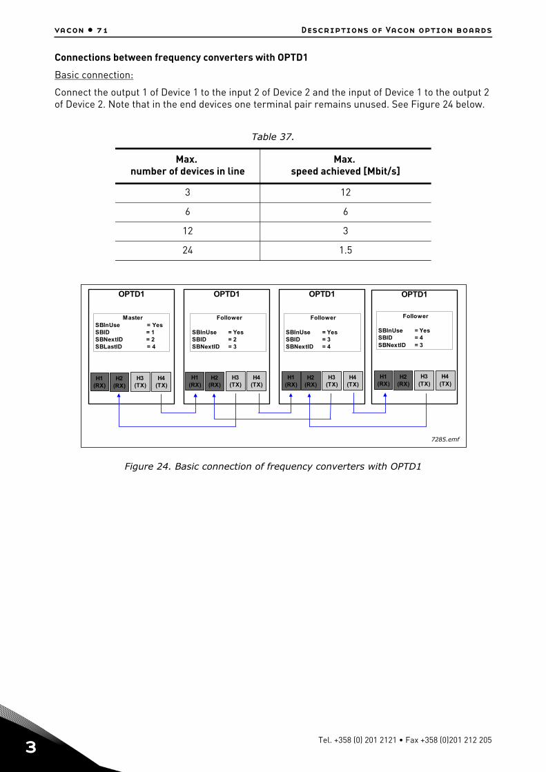
3
vacon • 71 Descriptions of Vacon option boards
Connections between frequency converters with OPTD1
Basic connection:
Connect the output 1 of Device 1 to the input 2 of Device 2 and the input of Device 1 to the output 2 of Device 2. Note that in the end devices one terminal pair remains unused. See Figure 24 below.
Figure 24. Basic connection of frequency converters with OPTD1
Table 37.
Max. number of devices in line
Max. speed achieved [Mbit/s]
3 12
6 6
12 3
24 1.5
OPTD1OPTD1OPTD1
MasterSBInUse = YesSBID = 1SBNextID = 2SBLastID = 4
Follower
SBInUse = YesSBID = 2SBNextID = 3
Follower
SBInUse = YesSBID = 3SBNextID = 4
H1(RX)
H3(TX)
H2(RX)
H4(TX)
OPTD1
Follower
SBInUse = YesSBID = 4SBNextID = 3
H1(RX)
H3(TX)
H2(RX)
H4(TX)
H1(RX)
H3(TX)
H2(RX)
H4(TX)
H1(RX)
H3(TX)
H2(RX)
H4(TX)
7285.emf
Tel. +358 (0) 201 2121 • Fax +358 (0)201 212 205
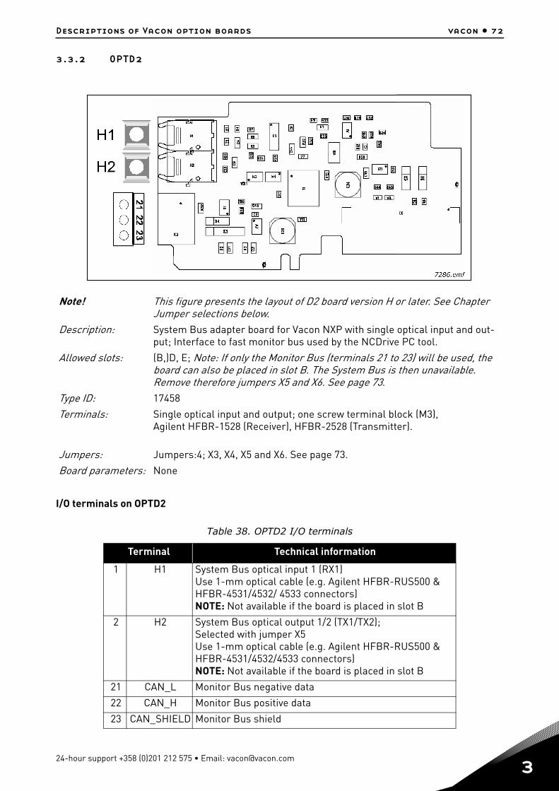
Descriptions of Vacon option boards vacon • 72
3.3.2 OPTD2
I/O terminals on OPTD2
Note! This figure presents the layout of D2 board version H or later. See Chapter Jumper selections below.
Description: System Bus adapter board for Vacon NXP with single optical input and out-put; Interface to fast monitor bus used by the NCDrive PC tool.
Allowed slots: (B,)D, E; Note: If only the Monitor Bus (terminals 21 to 23) will be used, the board can also be placed in slot B. The System Bus is then unavailable. Remove therefore jumpers X5 and X6. See page 73.
Type ID: 17458
Terminals: Single optical input and output; one screw terminal block (M3),Agilent HFBR-1528 (Receiver), HFBR-2528 (Transmitter).
Jumpers: Jumpers:4; X3, X4, X5 and X6. See page 73.
Board parameters: None
Table 38. OPTD2 I/O terminals
Terminal Technical information
1 H1 System Bus optical input 1 (RX1)Use 1-mm optical cable (e.g. Agilent HFBR-RUS500 & HFBR-4531/4532/ 4533 connectors)NOTE: Not available if the board is placed in slot B
2 H2 System Bus optical output 1/2 (TX1/TX2);Selected with jumper X5Use 1-mm optical cable (e.g. Agilent HFBR-RUS500 & HFBR-4531/4532/4533 connectors)NOTE: Not available if the board is placed in slot B
21 CAN_L Monitor Bus negative data
22 CAN_H Monitor Bus positive data
23 CAN_SHIELD Monitor Bus shield
24-hour support +358 (0)201 212 575 • Email: [email protected]

3
vacon • 73 Descriptions of Vacon option boards
Jumper selections
There are four jumper blocks on the OPTD2 board. The factory defaults and other available jumper selections are presented below.
Figure 25. Jumper selections for OPTD2, up to version G
Figure 26. X3 jumper selections for OPTD2, version H and later
NOTE! Position C can be used with 3- or 4-wire can cable to interconnect isolated CAN ground lev-els in the network. It is recommended to connect the cable shield to the grounding clamp of the drive
Jumper block X3:CAN grounding
Connected to shield Not connected to shield
Jumper block X4:CAN termination
Terminated Not terminated
Jumper block X5*:System bus output
Output TX1 Output TX2
Jumper block X6*:SystemBus input ON/OFF
ON OFF
= Factory default
*If the board is placed in slot B the SystemBus is notavailable. Remove jumpers X5 and X6.
7287.emf
Jumper block X3:CAN grounding
A B C
A: Connected to groundB: Connected to ground via LC filterC: Connected to CAN isolated groundNot assembled: No connectionSee further clarifications of the alternatives next page!
7288.emf
Tel. +358 (0) 201 2121 • Fax +358 (0)201 212 205
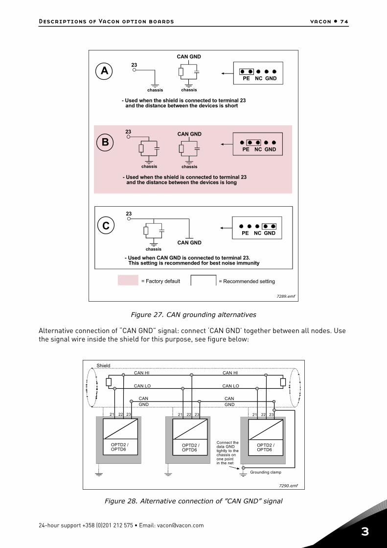
Descriptions of Vacon option boards vacon • 74
Figure 27. CAN grounding alternatives
Alternative connection of “CAN GND” signal: connect ‘CAN GND’ together between all nodes. Use the signal wire inside the shield for this purpose, see figure below:
Figure 28. Alternative connection of ”CAN GND” signal
PE NC GND
PE NC GND
PE NC GND
A23
chassis
CAN GND
chassis
- Used when the shield is connected to terminal 23and the distance between the devices is short
B
chassis chassis
23 CAN GND
- Used when the shield is connected to terminal 23and the distance between the devices is long
C23
CAN GNDchassis
- Used when CAN GND is connected to terminal 23.This setting is recommended for best noise immunity
= Factory default = Recommended setting
7289.emf
Shield
CAN HI CAN HI
CAN LO CAN LO
CANGND
CANGND
21 22 23
OPTD2 /OPTD6
OPTD2 /OPTD6
OPTD2 /OPTD6
Grounding clamp
Connect thedata GNDtightly to thechassis onone pointin the net
21 22 2321 22 23
7290.emf
24-hour support +358 (0)201 212 575 • Email: [email protected]
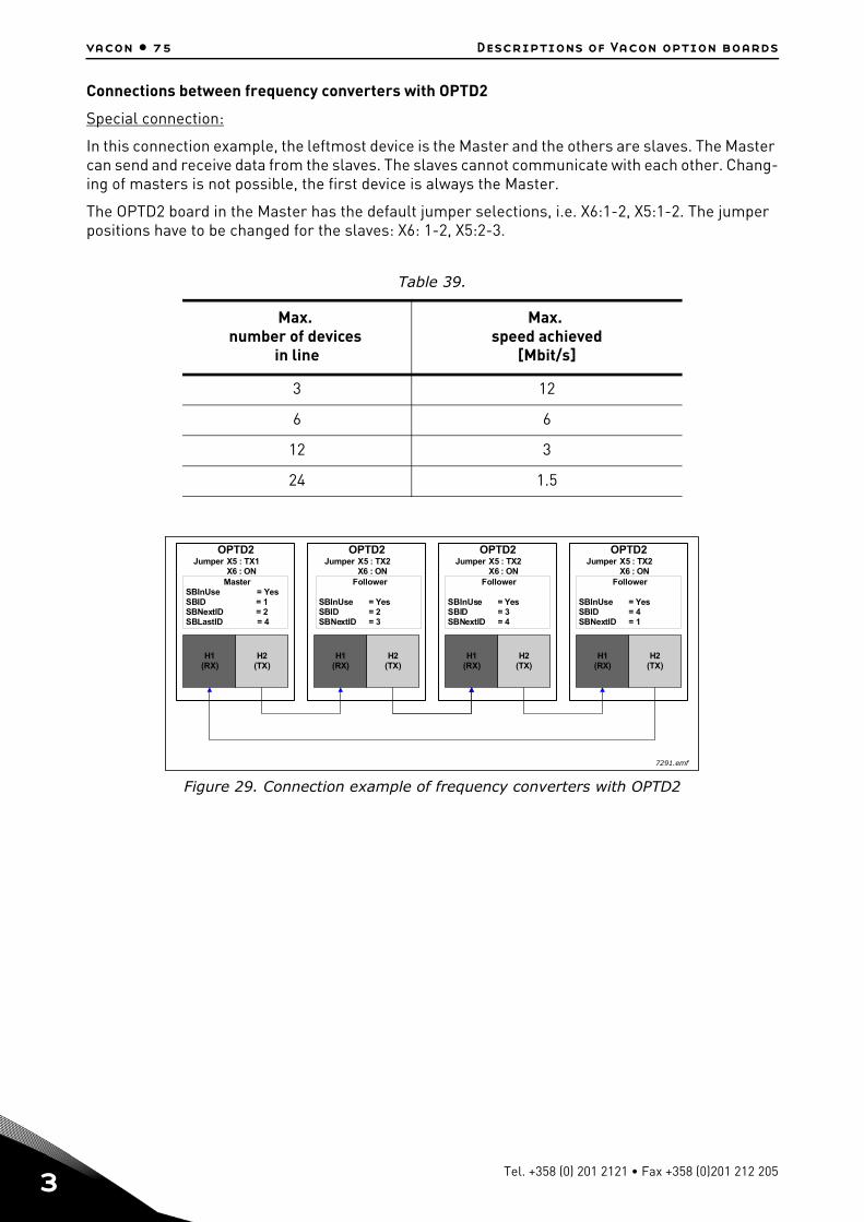
3
vacon • 75 Descriptions of Vacon option boards
Connections between frequency converters with OPTD2
Special connection:
In this connection example, the leftmost device is the Master and the others are slaves. The Master can send and receive data from the slaves. The slaves cannot communicate with each other. Chang-ing of masters is not possible, the first device is always the Master.
The OPTD2 board in the Master has the default jumper selections, i.e. X6:1-2, X5:1-2. The jumper positions have to be changed for the slaves: X6: 1-2, X5:2-3.
Figure 29. Connection example of frequency converters with OPTD2
Table 39.
Max. number of devices
in line
Max. speed achieved
[Mbit/s]
3 12
6 6
12 3
24 1.5
OPTD2Jumper X5 : TX2
X6 : ON
OPTD2Jumper X5 : TX2
X6 : ON
OPTD2Jumper X5 : TX2
X6 : ON
OPTD2Jumper X5 : TX1
X6 : ON
H1(RX)
H2(TX)
MasterSBInUse = YesSBID = 1SBNextID = 2SBLastID = 4
Follower
SBInUse = YesSBID = 2SBNextID = 3
Follower
SBInUse = YesSBID = 3SBNextID = 4
Follower
SBInUse = YesSBID = 4SBNextID = 1
H1(RX)
H1(RX)
H1(RX)
H2(TX)
H2(TX)
H2(TX)
7291.emf
Tel. +358 (0) 201 2121 • Fax +358 (0)201 212 205
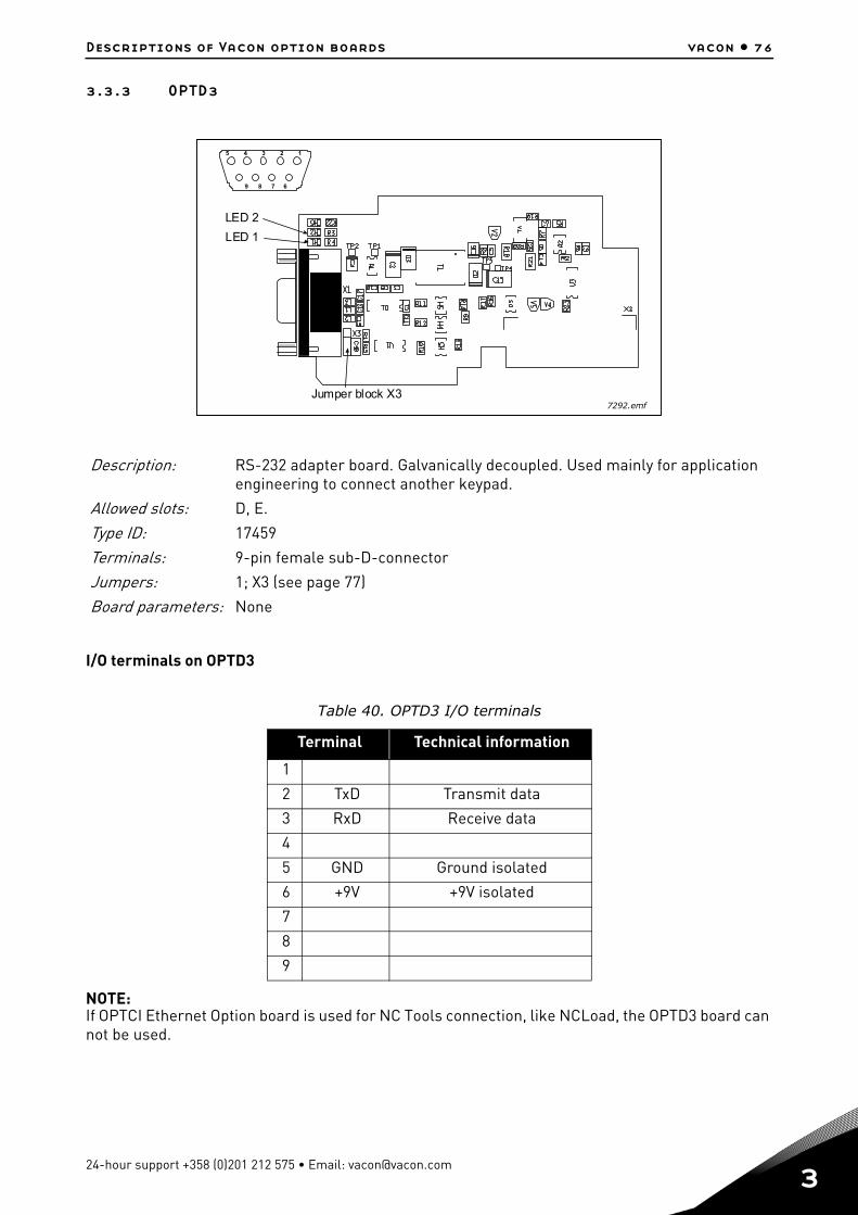
Descriptions of Vacon option boards vacon • 76
3.3.3 OPTD3
I/O terminals on OPTD3
NOTE:If OPTCI Ethernet Option board is used for NC Tools connection, like NCLoad, the OPTD3 board can not be used.
Description: RS-232 adapter board. Galvanically decoupled. Used mainly for application engineering to connect another keypad.
Allowed slots: D, E.
Type ID: 17459
Terminals: 9-pin female sub-D-connector
Jumpers: 1; X3 (see page 77)
Board parameters: None
Table 40. OPTD3 I/O terminals
Terminal Technical information
1
2 TxD Transmit data
3 RxD Receive data
4
5 GND Ground isolated
6 +9V +9V isolated
7
8
9
LED 1
LED 2
Jumper block X3
5 4 3 2 1
9 8 7 6
7292.emf
24-hour support +358 (0)201 212 575 • Email: [email protected]
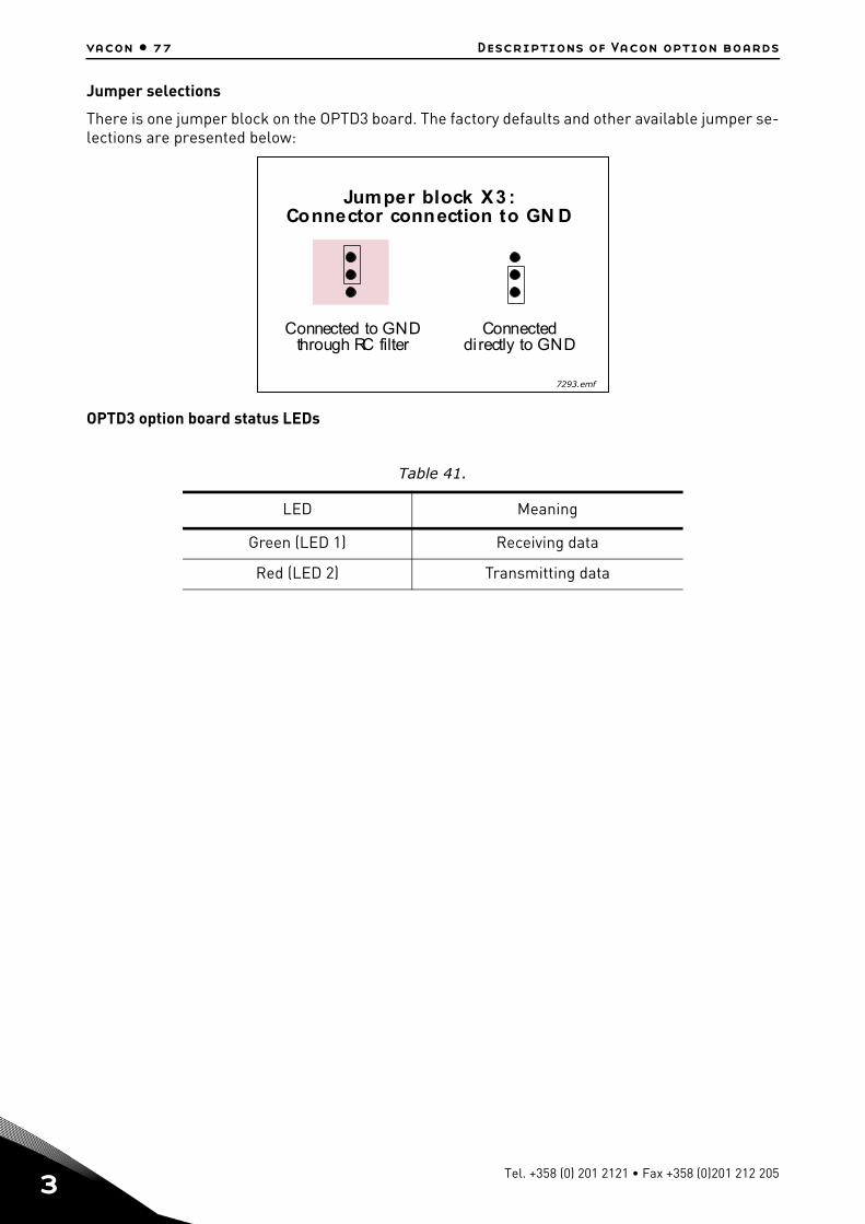
3
vacon • 77 Descriptions of Vacon option boards
Jumper selections
There is one jumper block on the OPTD3 board. The factory defaults and other available jumper se-lections are presented below:
OPTD3 option board status LEDs
Table 41.
LED Meaning
Green (LED 1) Receiving data
Red (LED 2) Transmitting data
Jumper block X3 :Connector connection to GN D
Connected to GNDthrough RC filter
Connecteddirectly to GND
7293.emf
Tel. +358 (0) 201 2121 • Fax +358 (0)201 212 205
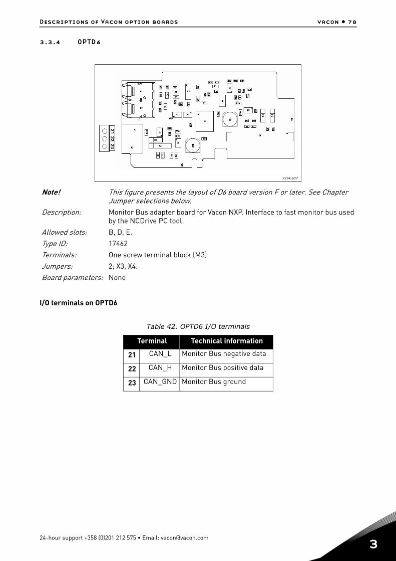
Descriptions of Vacon option boards vacon • 78
3.3.4 OPTD6
I/O terminals on OPTD6
Note! This figure presents the layout of D6 board version F or later. See Chapter Jumper selections below.
Description: Monitor Bus adapter board for Vacon NXP. Interface to fast monitor bus used by the NCDrive PC tool.
Allowed slots: B, D, E.
Type ID: 17462
Terminals: One screw terminal block (M3)
Jumpers: 2; X3, X4.
Board parameters: None
Table 42. OPTD6 I/O terminals
Terminal Technical information
21 CAN_L Monitor Bus negative data
22 CAN_H Monitor Bus positive data
23 CAN_GND Monitor Bus ground
7294.emf
24-hour support +358 (0)201 212 575 • Email: [email protected]
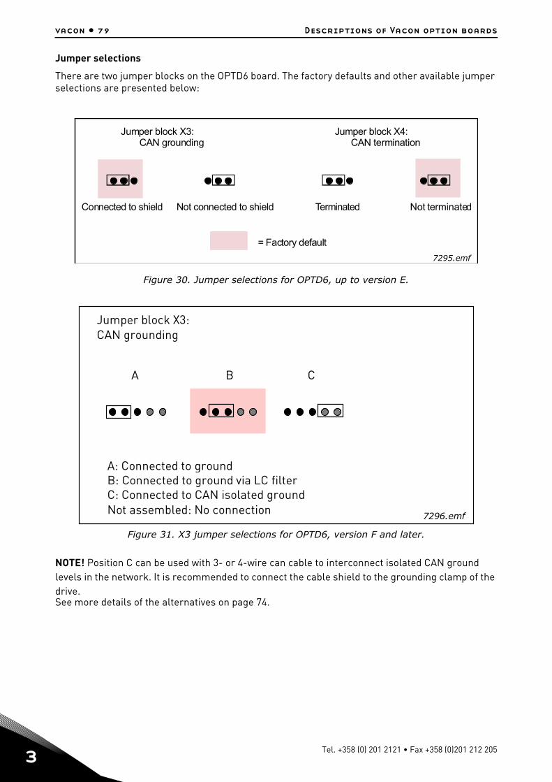
3
vacon • 79 Descriptions of Vacon option boards
Jumper selections
There are two jumper blocks on the OPTD6 board. The factory defaults and other available jumper selections are presented below:
Figure 30. Jumper selections for OPTD6, up to version E.
Figure 31. X3 jumper selections for OPTD6, version F and later.
NOTE! Position C can be used with 3- or 4-wire can cable to interconnect isolated CAN ground levels in the network. It is recommended to connect the cable shield to the grounding clamp of the drive.See more details of the alternatives on page 74.
Jumper block X3:CAN grounding
Connected to shield Not connected to shield
Jumper block X4:CAN termination
Terminated Not terminated
= Factory default
7295.emf
Jumper block X3:CAN grounding
A B C
A: Connected to groundB: Connected to ground via LC filterC: Connected to CAN isolated groundNot assembled: No connection 7296.emf
Tel. +358 (0) 201 2121 • Fax +358 (0)201 212 205
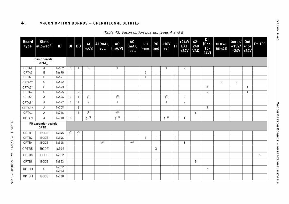
4
va
co
n •
8
0Va
co
n O
ptio
n B
oa
rd
s –
o
per
atio
na
l d
eta
ils
Tel. +358 (0) 201 2121 • Fax +358 (0)201 212 205
/ 42-240VAC
DI (Enc.10-
24V)
DI (Enc. RS-422)
Out +5/+15V/+24V
Out +15/+24V
Pt-100
3 1
3 1
6 1
3
6
3
5
2
4. VACON OPTION BOARDS – OPERATIONAL DETAILS
Table 43. Vacon option boards, types A and B
Board type
Slots allowed6) ID DI DO AI
(mA/V)AI (mA),
isol.AO
(mA/V)
AO (mA), isol.
RO (no/nc)
RO (no)
+10Vref TI
+24VEXT+24V
Basic boardsOPTA_
OPTA1 A 16689 6 1 2 1 1 2OPTA2 B 16690 2OPTA3 B 16691 1 1 1
OPTA44) C 16692
OPTA54) C 16693
OPTA7 C 16695 2
OPTA8 A 16696 6 1 21) 11) 11) 2
OPTA93) A 16697 6 1 2 1 1 2
OPTAE4) A 16709 2
OPTAL A 16716 1 28) 29)
OPTAN A 16718 6 210) 210) 111) 1
I/O expander boards OPTB_
OPTB1 BCDE 16945 65) 65)
OPTB2 BCDE 16946 1 1 1
OPTB4 BCDE 16948 12) 22) 1
OPTB5 BCDE 16949 3
OPTB8 BCDE 16952
OPTB9 BCDE 16953 1
OPTBB C1696216963
OPTBH BCDE 16968
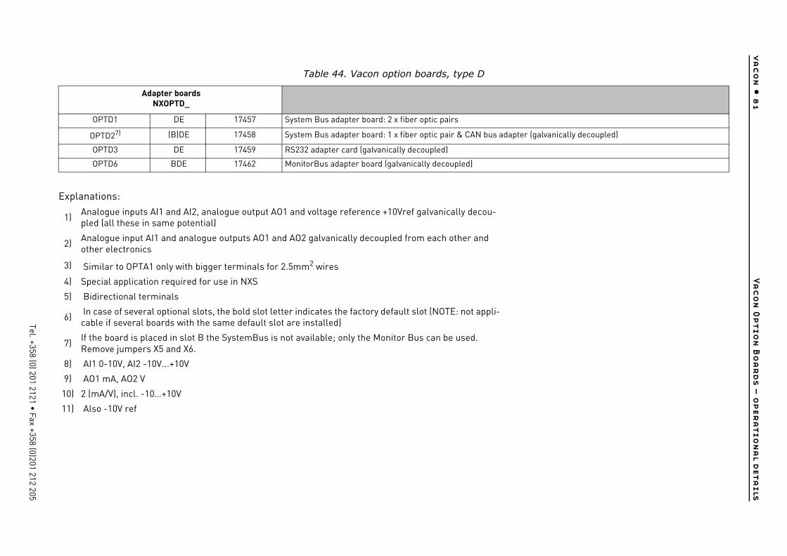
4
va
co
n •
8
1Va
co
n O
ptio
n B
oa
rd
s –
o
per
atio
na
l d
eta
ils
Tel. +358 (0) 201 2121 • Fax +358 (0)201 212 205
pter (galvanically decoupled)
Table 44. Vacon option boards, type D
Adapter boardsNXOPTD_
OPTD1 DE 17457 System Bus adapter board: 2 x fiber optic pairs
OPTD27) (B)DE 17458 System Bus adapter board: 1 x fiber optic pair & CAN bus ada
OPTD3 DE 17459 RS232 adapter card (galvanically decoupled)
OPTD6 BDE 17462 MonitorBus adapter board (galvanically decoupled)
Explanations:
1) Analogue inputs AI1 and AI2, analogue output AO1 and voltage reference +10Vref galvanically decou-pled (all these in same potential)
2) Analogue input AI1 and analogue outputs AO1 and AO2 galvanically decoupled from each other and other electronics
3) Similar to OPTA1 only with bigger terminals for 2.5mm2 wires
4) Special application required for use in NXS
5) Bidirectional terminals
6) In case of several optional slots, the bold slot letter indicates the factory default slot (NOTE: not appli-cable if several boards with the same default slot are installed)
7)If the board is placed in slot B the SystemBus is not available; only the Monitor Bus can be used. Remove jumpers X5 and X6.
8) AI1 0-10V, AI2 -10V...+10V
9) AO1 mA, AO2 V
10) 2 (mA/V), incl. -10…+10V
11) Also -10V ref
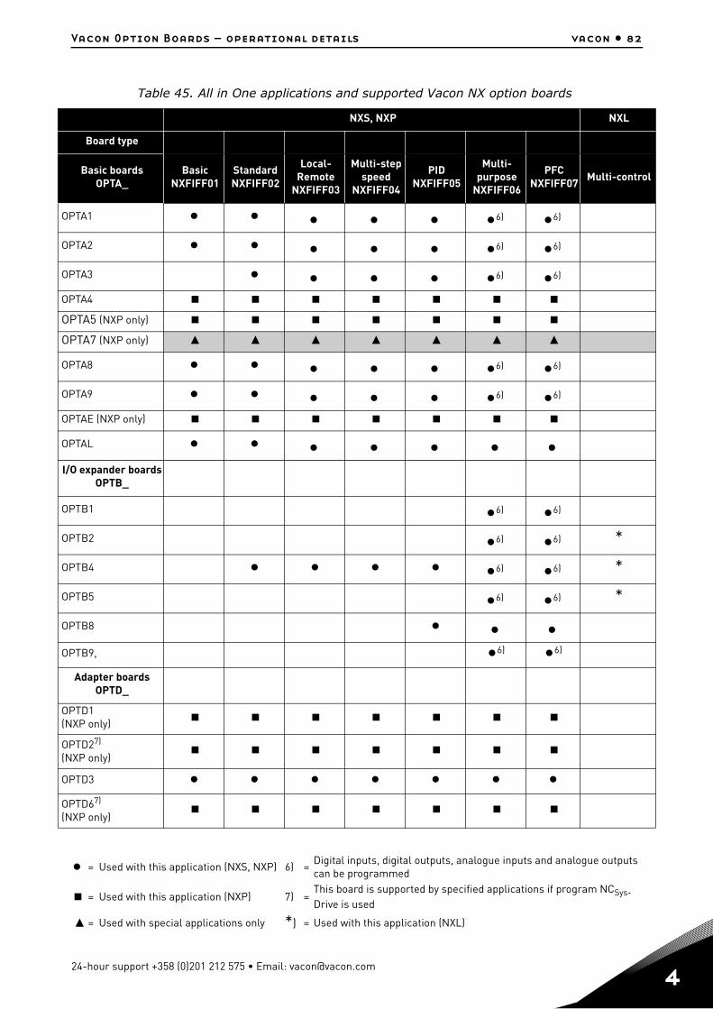
Vacon Option Boards – operational details vacon • 82
Table 45. All in One applications and supported Vacon NX option boards
NXS, NXP NXL
Board type
Basic boardsOPTA_
BasicNXFIFF01
StandardNXFIFF02
Local-Remote
NXFIFF03
Multi-step speed
NXFIFF04
PIDNXFIFF05
Multi-purpose
NXFIFF06
PFCNXFIFF07
Multi-control
OPTA1 6) 6)
OPTA2 6) 6)
OPTA3 6) 6)
OPTA4
OPTA5 (NXP only)
OPTA7 (NXP only)
OPTA8 6) 6)
OPTA9 6) 6)
OPTAE (NXP only)
OPTAL I/O expander boards
OPTB_
OPTB1 6) 6)
OPTB2 6) 6) *
OPTB4 6) 6) *
OPTB5 6) 6) *
OPTB8 OPTB9, 6) 6)
Adapter boardsOPTD_
OPTD1 (NXP only)
OPTD27)
(NXP only)
OPTD3 OPTD67)
(NXP only)
= Used with this application (NXS, NXP) 6) =Digital inputs, digital outputs, analogue inputs and analogue outputs can be programmed
= Used with this application (NXP) 7) =This board is supported by specified applications if program NCSys-Drive is used
= Used with special applications only *) = Used with this application (NXL)
24-hour support +358 (0)201 212 575 • Email: [email protected]

Document ID:
Rev. A
Manual authoring:[email protected]
Vacon Plc.Runsorintie 765380 VaasaFinland
Subject to change without prior notice© 2011 Vacon Plc.
Find your nearest Vacon office on the Internet at:
www.vacon.com
Find your nearest Vacon service centre on the Extranet at:
www.extra.vacon.com